EP3474376B1 - Broadband antenna system - Google Patents
Broadband antenna system Download PDFInfo
- Publication number
- EP3474376B1 EP3474376B1 EP17382689.2A EP17382689A EP3474376B1 EP 3474376 B1 EP3474376 B1 EP 3474376B1 EP 17382689 A EP17382689 A EP 17382689A EP 3474376 B1 EP3474376 B1 EP 3474376B1
- Authority
- EP
- European Patent Office
- Prior art keywords
- antenna
- ground plane
- antenna system
- radiating element
- lateral segments
- Prior art date
- Legal status (The legal status is an assumption and is not a legal conclusion. Google has not performed a legal analysis and makes no representation as to the accuracy of the status listed.)
- Active
Links
- 230000007774 longterm Effects 0.000 claims description 3
- PEZNEXFPRSOYPL-UHFFFAOYSA-N (bis(trifluoroacetoxy)iodo)benzene Chemical compound FC(F)(F)C(=O)OI(OC(=O)C(F)(F)F)C1=CC=CC=C1 PEZNEXFPRSOYPL-UHFFFAOYSA-N 0.000 description 7
- 230000001413 cellular effect Effects 0.000 description 5
- 230000008901 benefit Effects 0.000 description 4
- 230000005855 radiation Effects 0.000 description 3
- 238000009434 installation Methods 0.000 description 2
- 230000003071 parasitic effect Effects 0.000 description 2
- 241000251730 Chondrichthyes Species 0.000 description 1
- 238000005452 bending Methods 0.000 description 1
- 230000001808 coupling effect Effects 0.000 description 1
- 230000000694 effects Effects 0.000 description 1
- 230000003993 interaction Effects 0.000 description 1
- 238000004519 manufacturing process Methods 0.000 description 1
- 230000005226 mechanical processes and functions Effects 0.000 description 1
- 230000035945 sensitivity Effects 0.000 description 1
Images


Classifications
-
- H—ELECTRICITY
- H01—ELECTRIC ELEMENTS
- H01Q—ANTENNAS, i.e. RADIO AERIALS
- H01Q1/00—Details of, or arrangements associated with, antennas
- H01Q1/48—Earthing means; Earth screens; Counterpoises
-
- H—ELECTRICITY
- H01—ELECTRIC ELEMENTS
- H01Q—ANTENNAS, i.e. RADIO AERIALS
- H01Q1/00—Details of, or arrangements associated with, antennas
- H01Q1/36—Structural form of radiating elements, e.g. cone, spiral, umbrella; Particular materials used therewith
-
- H—ELECTRICITY
- H01—ELECTRIC ELEMENTS
- H01Q—ANTENNAS, i.e. RADIO AERIALS
- H01Q1/00—Details of, or arrangements associated with, antennas
- H01Q1/12—Supports; Mounting means
- H01Q1/22—Supports; Mounting means by structural association with other equipment or articles
- H01Q1/24—Supports; Mounting means by structural association with other equipment or articles with receiving set
- H01Q1/241—Supports; Mounting means by structural association with other equipment or articles with receiving set used in mobile communications, e.g. GSM
-
- H—ELECTRICITY
- H01—ELECTRIC ELEMENTS
- H01Q—ANTENNAS, i.e. RADIO AERIALS
- H01Q1/00—Details of, or arrangements associated with, antennas
- H01Q1/27—Adaptation for use in or on movable bodies
- H01Q1/32—Adaptation for use in or on road or rail vehicles
- H01Q1/3208—Adaptation for use in or on road or rail vehicles characterised by the application wherein the antenna is used
- H01Q1/3233—Adaptation for use in or on road or rail vehicles characterised by the application wherein the antenna is used particular used as part of a sensor or in a security system, e.g. for automotive radar, navigation systems
-
- H—ELECTRICITY
- H01—ELECTRIC ELEMENTS
- H01Q—ANTENNAS, i.e. RADIO AERIALS
- H01Q1/00—Details of, or arrangements associated with, antennas
- H01Q1/50—Structural association of antennas with earthing switches, lead-in devices or lightning protectors
-
- H—ELECTRICITY
- H01—ELECTRIC ELEMENTS
- H01Q—ANTENNAS, i.e. RADIO AERIALS
- H01Q21/00—Antenna arrays or systems
- H01Q21/06—Arrays of individually energised antenna units similarly polarised and spaced apart
- H01Q21/061—Two dimensional planar arrays
- H01Q21/065—Patch antenna array
-
- H—ELECTRICITY
- H01—ELECTRIC ELEMENTS
- H01Q—ANTENNAS, i.e. RADIO AERIALS
- H01Q21/00—Antenna arrays or systems
- H01Q21/28—Combinations of substantially independent non-interacting antenna units or systems
-
- H—ELECTRICITY
- H01—ELECTRIC ELEMENTS
- H01Q—ANTENNAS, i.e. RADIO AERIALS
- H01Q5/00—Arrangements for simultaneous operation of antennas on two or more different wavebands, e.g. dual-band or multi-band arrangements
- H01Q5/30—Arrangements for providing operation on different wavebands
-
- H—ELECTRICITY
- H01—ELECTRIC ELEMENTS
- H01Q—ANTENNAS, i.e. RADIO AERIALS
- H01Q9/00—Electrically-short antennas having dimensions not more than twice the operating wavelength and consisting of conductive active radiating elements
- H01Q9/04—Resonant antennas
- H01Q9/0407—Substantially flat resonant element parallel to ground plane, e.g. patch antenna
- H01Q9/0414—Substantially flat resonant element parallel to ground plane, e.g. patch antenna in a stacked or folded configuration
-
- H—ELECTRICITY
- H01—ELECTRIC ELEMENTS
- H01Q—ANTENNAS, i.e. RADIO AERIALS
- H01Q9/00—Electrically-short antennas having dimensions not more than twice the operating wavelength and consisting of conductive active radiating elements
- H01Q9/04—Resonant antennas
- H01Q9/0407—Substantially flat resonant element parallel to ground plane, e.g. patch antenna
- H01Q9/0421—Substantially flat resonant element parallel to ground plane, e.g. patch antenna with a shorting wall or a shorting pin at one end of the element
-
- H—ELECTRICITY
- H01—ELECTRIC ELEMENTS
- H01Q—ANTENNAS, i.e. RADIO AERIALS
- H01Q9/00—Electrically-short antennas having dimensions not more than twice the operating wavelength and consisting of conductive active radiating elements
- H01Q9/04—Resonant antennas
- H01Q9/30—Resonant antennas with feed to end of elongated active element, e.g. unipole
- H01Q9/42—Resonant antennas with feed to end of elongated active element, e.g. unipole with folded element, the folded parts being spaced apart a small fraction of the operating wavelength
-
- H—ELECTRICITY
- H01—ELECTRIC ELEMENTS
- H01Q—ANTENNAS, i.e. RADIO AERIALS
- H01Q1/00—Details of, or arrangements associated with, antennas
- H01Q1/27—Adaptation for use in or on movable bodies
- H01Q1/32—Adaptation for use in or on road or rail vehicles
Definitions
- the present invention refers in general to broadband and multiband antennas, preferably to be used as remote antennas for vehicles.
- An object of the invention is to provide a broadband and multiband antenna of reduced dimensions, that can be fitted within a confined space for example inside a vehicle.
- Another object of the invention is to provide a remote antenna for vehicles that can be simply attached by itself, that is, without additional attaching means, to a vehicle, and without ground connection to the vehicle, thereby reducing manufacturing costs.
- Another advantage of the external antenna respect internal antennas is its performance in terms of electronic noise. Internal antennas should obtain worst sensitivity of the whole system as being nearer of the electronic noise sources (clocks, microprocessors, etc.). Therefore, in case of the external antennas this situation is improved as they can be moved out from these noise sources.
- LTE antennas in particular require at the same time both a main antenna and a diversity antenna.
- these two LTE antennas (main and diversity) cannot be accommodated in the narrow interior of a shark fin antenna, especially in the low frequency band (700 MHz - 1 GHz), wherein signal interference is high, and the level of the uncorrelation obtained between the antennas will be poor.
- antennas When more than one antenna is needed on a mobile system as LTE, antennas must be as uncorrelated as possible between them.
- planar inverted F antennas are commonly used in wireless communications, e.g., cellular telephones, wireless personal digital assistants (PDAs), wireless local area networks (LANs)-Bluetooth, etc.
- a PIFA antenna generally includes a planar radiating element, and a ground plane that is parallel to the radiating element, wherein this ground plane is larger than the antenna's structure.
- An electrically conductive first line is coupled to the radiating element at a first contact located at an edge on a side of the radiating element, and that first line is also coupled to the ground plane.
- An electrically conductive second line is coupled to the radiating element along the same side as the first line, but at a different contact location on the edge than the first line.
- the first and second lines are adapted to couple to a desired impedance, e.g., 50 ohms, at frequencies of operation of the PIFA.
- the first and second lines are perpendicular to the edge of the radiating element to which they are coupled, thereby forming an inverted F shape (thus the descriptive name of planar inverted F antenna).
- Prior known planar inverted F antennas have sacrificed bandwidth by requiring a reduction in the volume of the PIFA for a given wireless application. Moreover, their performance is strongly related with the physical dimensions of the ground plane where the antenna is connected. Normally, for properly functionality at lowest frequency of the cellular bands (as example of LTE) a ground plane larger than 100 mm is needed.
- WO2012/001729A1 discloses a planar inverted-F antenna of a compact design for multi-band operation comprising a ground plane, a radiating element spaced from the ground plane and extending substantially parallel thereto and having substantially a U-shape, two shorting elements located at a corner (or adjacent area) of the radiating element and two feed ports electrically connected to the radiating element.
- WO 2015/164010 A1 discloses an antenna system with a ⁇ -shaped planar radiating element coplanar with a ground plane, the antenna being fed via a feeding line and a ground line directly connected to the ⁇ -shaped radiating element.
- US 2016/197395 A1 discloses an antenna system with a U-shaped planar radiating element above and parallel to a ground plane, the antenna being fed via feeding lines connected to a controller and with a satellite navigation antenna (GNSS) arranged between the two lateral segments of a U-shaped radiating element.
- GNSS satellite navigation antenna
- WOJCIECH J KRZYSZTOFIK ED - ANONYMOUS "Meandered Double-PIFA Antenna - Handset / Human Interaction" discloses a meandered double-PIFA antenna above a ground plane.
- US 2014/266926 A1 , US 2017/279184 A1 , and US 2017/025740 A1 disclose an antenna system with a U-shaped planar radiating element coplanar with a ground plane, the antenna being fed via a feeding line and a ground line directly connected to the U-shaped radiating element.
- US 2006/250310 A1 discloses an antenna system with a PIFA radiating element coplanar with a ground plane having slots.
- US 2005/024272 A1 discloses an antenna system with a U-shaped planar parasitic radiating element above and parallel to a conductive sheet including a slot, both the parasitic element and the conductive sheet being above and parallel to a PCB containing a ground plane with a feeding structure via feed lines connected between the PCB and the conductive sheet.
- the antenna of the invention includes two inverted F antennas in order to increase antenna efficiency, in terms of radiation and bandwidth, so that due to the co-operation between the two F antennas, the size of the ground plane is reduced.
- the antenna can be implemented either as a 2D planar antenna, or as a 3D volumetric antenna.
- An aspect of the invention refers to a broadband and multiband antenna system including an antenna device which comprises: a substantially planar ground plane and a substantially planar radiating element.
- the radiating element and the ground plane are coplanar, and in the 3D implementation the radiating element is arranged above the ground plane and it is substantially parallel to the ground plane.
- the radiating element has a central segment and first and second lateral segments extending from the central segment.
- the ground plane and the central segment of the radiating element are connected, and the ground plane has at least one slot, the slot having two edges, so that a feed line of the antenna system, namely a feed terminal and a ground terminal, are connected respectively with said edges.
- the radiating element has a U-shaped configuration, formed by a central segment and first and second lateral segments extending from the central segment.
- the radiating element and the ground plane are configured as a double PIFA antenna.
- the segments of the radiating element are substantially straight, and the first and second lateral segments are substantially parallel to each other and substantially orthogonal to the central segment.
- the ground plane has a substantially rectangular configuration with two short sides and two longer sides, and the central segment is placed above one of the short sides, and the lateral segments are placed respectively above the longer sides.
- the antenna system of the invention is preferably adapted to operate at least within one Long Term Evolution (LTE) frequency band, and to be used as remote antenna for a motor vehicle.
- LTE Long Term Evolution
- the antenna can be implemented either as a 2D planar antenna, or as a 3D volumetric antenna. In the case of a planar implementation as shown in drawing 1B, the antenna configuration could be defined as " ⁇ antenna".
- the ⁇ antenna shown in drawing 1B comprises a radiating element (3) having a first and second lateral segments (3b, 3c) extending from a central segment (3a) of length (L3).
- the lengths (L1, L2) of the first and second lateral segments (3b, 3c) are similar (+/- 15%), and they are selected depending on a first side (Y) of the ground plane (2) perpendicular to the radiant element (3) for each particular application.
- the radiating element (3) and the ground plane (2) are coplanar.
- the first, second and central segments (3a,3b,3c) are straight and are aligned, and are placed at one side of the ground plane (2).
- the distance (H) has a minimum value to avoid higher coupling effect to the ground-plane, that would reduce the antennas impedance and bandwidth.
- minimum H value is around 0.05 ⁇ , in the case of cellular band with the lowest frequency of operation at 700 MHz, the minimum value for "H" will be around 20 mm.
- a feed connection line (4) is connected between the central segment (3a) and a side of the ground plane (2), and a ground connection line (5) is connected between the central segment (3a) and the same side of the ground plane (2) to which the feed connection line (4) is connected. Therefore, the radiating element (3) and the feed and ground connection lines (4,5) together configure a " ⁇ " shape.
- a gap (G) between connection lines (4,5) of the " ⁇ antenna” outside the scope of this invention also has an influence of the antenna's radiation property, as the two inverted “F” antennas are not excited properly.
- the range of values to obtain the benefits of the new " ⁇ antenna” is over the range 0.035 to 0.05 ⁇ , therefore in the case of cellular band with the lowest frequency of operation at 700 MHz the range should be 15 to 20 mm.
- a 3D compact solution is obtained as an evolution of figure 1 , by bending first and second lateral segments (3b,3c) to form a "U" shape.
- the width (W) of this U-shape (corresponding approximately to the length L3 of the central segment (3a)) is similar than the length of a second side (X) of the ground plane (2), said second side (X) being perpendicular to the first side (Y).
- the radiant element (3) is firstly folded 90° respectively about a folding axis (x1), and finally the connection lines (4,5) are folded 90 ° respectively about folding axis (x2) as shown in drawing 2, to form a 3D implementation as an "U" shaped antenna ( figure 2B ).
- Figure 3 shows an example of an antenna (1) outside the scope of the invention, comprising a planar ground plane (2) and a planar radiating element (3) arranged above the ground plane (2) and substantially parallel to the ground plane (2).
- the radiating element (3) has a U-shaped configuration, having a central segment (3a) and first and second lateral segments (3b, 3c) extending from the central segment (3a).
- the segments (3a, 3b, 3c) of the radiating element (3) are straight and contains a rectangular part.
- the first and second lateral segments (3b, 3c) are parallel to each other and orthogonal to the central segment (3a).
- the first and second lateral segments (3b, 3c) are placed right above two parallel sides of the ground plane (2).
- the ground plane (2) has a generally rectangular configuration having two pairs of parallel sides, and wherein the central segment (3a) is placed above one side, and the lateral segments (3b, 3c) are placed respectively above the other two perpendicular sides.
- the lateral segment (3b) is longer than segment (3c).
- segment (3b) is longer than the ground plane (2).
- Segment (3c) is shorter than the ground plane (2), and its free end is bended towards the center of the ground plane, configuring an "L" shape.
- the gap (G) between connection lines (4,5) is avoided by using a slot on the ground-plane (2).
- This slot generates an electrical path between points equivalent to the gap (G) with the advantage of reducing also the lowest frequency of operation of the antenna.
- the ground plane (2) has at least one slot (8) as a tuning antenna slot (8) for tuning the antenna to the desired operating frequency.
- the ground plane (2) may have other slots (8) with mechanical function as part of fixation means.
- the ground plane (2) has a part bended (2a) over to be used as a bracket for installing the antenna.
- the antenna (2) is complemented with a printed circuit board (6) attached to the ground plane (2), wherein the printed circuit board (6) has a matching network for the antenna system, and a coaxial cable (7) for the antenna output.
- the tuning antenna slot (8) is a straight groove having two edges (9), so that a feed line of the antenna system (having two terminals, not shown), namely a feed terminal and a ground terminal), are connected respectively with said edges (9).
- the position and shape of the slot (8) configure two paths for the current circulation in the ground plane.
- Figure 5A shows an embodiment outside the scope of the present invention wherein the distance (d) between the first and second lateral segments (3b, 3c) is about 0.1 ⁇ , ⁇ being the lowest frequency of operation.
- Figure 5B shows an embodiment outside the scope of the invention, wherein the height (H) between the radiating element (3) and the ground plane (2) is higher than 0.05A, ⁇ being the lowest frequency of operation.
- Figure 5D shows an embodiment according to the invention, wherein the gap (G) between the two connection lines (4, 5) is equal to 0, and the ground plane (2) has a slot (8) with a total perimeter around 0.25 A; and figure 6 , also shows a graph corresponding to the measured VSWR (Voltage Standing Wave Ratio), showing the effects of that slot (8), getting the GND to be resonant at lowest frequencies than the obtained with the design with the two connection lines (4, 5) separated, being the lowest frequency of operation.
- VSWR Voltage Standing Wave Ratio
- the antenna system is adapted to operate at least within one Long Term Evolution (LTE) frequency band.
- LTE Long Term Evolution
- the lowest frequency of operation is 700 MHz.
- figure 7 shows a complete antenna system comprising the antenna (1) previously described, an additionally including a satellite navigation antenna (GNSS) (10), and a casing (12) to protect and isolate the antenna.
- GNSS satellite navigation antenna
- the GNSS antenna (10) is arranged between these two lateral segments.
- the antenna system is characterized by the following combination of features and properties:
Landscapes
- Engineering & Computer Science (AREA)
- Computer Security & Cryptography (AREA)
- Radar, Positioning & Navigation (AREA)
- Remote Sensing (AREA)
- Computer Networks & Wireless Communication (AREA)
- Waveguide Aerials (AREA)
- Details Of Aerials (AREA)
- Variable-Direction Aerials And Aerial Arrays (AREA)
Description
- The present invention refers in general to broadband and multiband antennas, preferably to be used as remote antennas for vehicles.
- An object of the invention is to provide a broadband and multiband antenna of reduced dimensions, that can be fitted within a confined space for example inside a vehicle.
- Another object of the invention is to provide a remote antenna for vehicles that can be simply attached by itself, that is, without additional attaching means, to a vehicle, and without ground connection to the vehicle, thereby reducing manufacturing costs.
- Due to the large size of some electronic devices, it is difficult to accommodate a large antenna system inside a reduced space. For this reason, many communication devices of motor vehicles require external antennas to increase the performance of an internal antenna. In that scenario, it is critical that the dimension of the external antenna be as small as possible so that it can be fitted inside a reduced space within a vehicle.
- Another advantage of the external antenna respect internal antennas is its performance in terms of electronic noise. Internal antennas should obtain worst sensitivity of the whole system as being nearer of the electronic noise sources (clocks, microprocessors, etc.). Therefore, in case of the external antennas this situation is improved as they can be moved out from these noise sources.
- For example, LTE antennas in particular require at the same time both a main antenna and a diversity antenna. However, these two LTE antennas (main and diversity) cannot be accommodated in the narrow interior of a shark fin antenna, especially in the low frequency band (700 MHz - 1 GHz), wherein signal interference is high, and the level of the uncorrelation obtained between the antennas will be poor. When more than one antenna is needed on a mobile system as LTE, antennas must be as uncorrelated as possible between them.
- On the other hand, planar inverted F antennas (PIFAs) are commonly used in wireless communications, e.g., cellular telephones, wireless personal digital assistants (PDAs), wireless local area networks (LANs)-Bluetooth, etc. A PIFA antenna generally includes a planar radiating element, and a ground plane that is parallel to the radiating element, wherein this ground plane is larger than the antenna's structure. An electrically conductive first line is coupled to the radiating element at a first contact located at an edge on a side of the radiating element, and that first line is also coupled to the ground plane.
- An electrically conductive second line is coupled to the radiating element along the same side as the first line, but at a different contact location on the edge than the first line. The first and second lines are adapted to couple to a desired impedance, e.g., 50 ohms, at frequencies of operation of the PIFA. In the PIFA, the first and second lines are perpendicular to the edge of the radiating element to which they are coupled, thereby forming an inverted F shape (thus the descriptive name of planar inverted F antenna).
- Prior known planar inverted F antennas have sacrificed bandwidth by requiring a reduction in the volume of the PIFA for a given wireless application. Moreover, their performance is strongly related with the physical dimensions of the ground plane where the antenna is connected. Normally, for properly functionality at lowest frequency of the cellular bands (as example of LTE) a ground plane larger than 100 mm is needed.
-
WO2012/001729A1 discloses a planar inverted-F antenna of a compact design for multi-band operation comprising a ground plane, a radiating element spaced from the ground plane and extending substantially parallel thereto and having substantially a U-shape, two shorting elements located at a corner (or adjacent area) of the radiating element and two feed ports electrically connected to the radiating element. -
WO 2015/164010 A1 discloses an antenna system with a π-shaped planar radiating element coplanar with a ground plane, the antenna being fed via a feeding line and a ground line directly connected to the π-shaped radiating element. -
US 2016/197395 A1 discloses an antenna system with a U-shaped planar radiating element above and parallel to a ground plane, the antenna being fed via feeding lines connected to a controller and with a satellite navigation antenna (GNSS) arranged between the two lateral segments of a U-shaped radiating element. - WOJCIECH J KRZYSZTOFIK ED - ANONYMOUS: "Meandered Double-PIFA Antenna - Handset / Human Interaction" discloses a meandered double-PIFA antenna above a ground plane.
-
US 2014/266926 A1 ,US 2017/279184 A1 , andUS 2017/025740 A1 disclose an antenna system with a U-shaped planar radiating element coplanar with a ground plane, the antenna being fed via a feeding line and a ground line directly connected to the U-shaped radiating element. -
US 2006/250310 A1 discloses an antenna system with a PIFA radiating element coplanar with a ground plane having slots. -
US 2005/024272 A1 discloses an antenna system with a U-shaped planar parasitic radiating element above and parallel to a conductive sheet including a slot, both the parasitic element and the conductive sheet being above and parallel to a PCB containing a ground plane with a feeding structure via feed lines connected between the PCB and the conductive sheet. - Therefore, there is a need for improving the bandwidth of a PIFA without having to increase the volume thereof, and without using larger ground plane for the antenna installation.
- Furthermore, it is a challenge to integrate a multiband, high efficient, low VSWR antenna in this reduced dimension.
- The invention is defined in the attached independent claim.
- The antenna of the invention includes two inverted F antennas in order to increase antenna efficiency, in terms of radiation and bandwidth, so that due to the co-operation between the two F antennas, the size of the ground plane is reduced. The antenna can be implemented either as a 2D planar antenna, or as a 3D volumetric antenna.
- An aspect of the invention refers to a broadband and multiband antenna system including an antenna device which comprises: a substantially planar ground plane and a substantially planar radiating element. In the 2D planar antenna, the radiating element and the ground plane are coplanar, and in the 3D implementation the radiating element is arranged above the ground plane and it is substantially parallel to the ground plane.
- The radiating element has a central segment and first and second lateral segments extending from the central segment.
- The ground plane and the central segment of the radiating element are connected, and the ground plane has at least one slot, the slot having two edges, so that a feed line of the antenna system, namely a feed terminal and a ground terminal, are connected respectively with said edges.
- The radiating element has a U-shaped configuration, formed by a central segment and first and second lateral segments extending from the central segment.
- Preferably, the radiating element and the ground plane are configured as a double PIFA antenna.
- Preferably, the segments of the radiating element are substantially straight, and the first and second lateral segments are substantially parallel to each other and substantially orthogonal to the central segment. The ground plane has a substantially rectangular configuration with two short sides and two longer sides, and the central segment is placed above one of the short sides, and the lateral segments are placed respectively above the longer sides.
- The antenna system of the invention is preferably adapted to operate at least within one Long Term Evolution (LTE) frequency band, and to be used as remote antenna for a motor vehicle.
- Some of the advantages of the invention are the followings:
- High efficiency;
- Wideband behavior;
- Multiband behavior;
- Ultra reduced dimensions compared with prior solutions;
- All in one part (antenna + bracket) no additional structures for installation;
- Compatible with navigation antenna integrated inside.
- Preferred embodiments of the invention, are henceforth described with reference to the accompanying drawings, wherein:
-
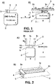
Figure 1 .- shows an schematic representation of the 2D planar antenna topology wherein drawing A is a prior-art inverted F antenna, and drawing B is a π antenna with a feeding structure outside the scope of the invention. -
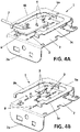
Figure 2 .- shows a schematic representation of the evolution of the 2D planar antenna offigure 1 , to be converted into a 3D volumetric antenna, wherein drawing 2A shows a first step of the evolution, and drawing 2B shows the final 3D antenna with a feeding structure outside the scope of this invention. -
Figure 3 .- shows in drawings A and B, a perspective view and a top plan view respectively, of a schematic representation of an antenna with a feeding structure outside the scope of this invention. -
Figures 4 .- shows two perspective views of an exemplary implementation of the antenna system according to the invention. -
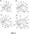
Figure 5 .- shows in perspective view, several schematic representations of the antenna withfigures 5A to 5C being outside the scope of the invention andfigure 5D being an antenna according to the invention. -
Figure 6 .- shows a graph corresponding to the measured VSWR (Voltage Standing Wave Ratio). -
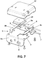
Figure 7 .- shows an exploded view of an antenna system according to the invention. - The antenna can be implemented either as a 2D planar antenna, or as a 3D volumetric antenna. In the case of a planar implementation as shown in drawing 1B, the antenna configuration could be defined as "π antenna".
- The π antenna shown in drawing 1B comprises a radiating element (3) having a first and second lateral segments (3b, 3c) extending from a central segment (3a) of length (L3). The lengths (L1, L2) of the first and second lateral segments (3b, 3c) are similar (+/- 15%), and they are selected depending on a first side (Y) of the ground plane (2) perpendicular to the radiant element (3) for each particular application.
- In this embodiment, the radiating element (3) and the ground plane (2) are coplanar. In addition, the first, second and central segments (3a,3b,3c) are straight and are aligned, and are placed at one side of the ground plane (2).
- Optimal implementation is obtained with the ratio of L1+H length being around 50-70%, preferably 55-65%, and more preferably 60%, greater than the ground plane axis dimension "Y" as shown in drawing 1B, and wherein (H) is the distance between the radiating element (3) and one side of the ground-plane (2) as represented in drawing 1B.
- For example in the case of an implementation of a cellular band with the lowest frequency of operation at 700 MHz (λ ~ 428 mm), and with an implementation of the ground-plane with "Y" dimension ~ 0.12 λ (50 mm), it requires L1 (63 mm) + H (20 mm). In this case Y / (L1+H) results in 50 / (63 +20) = 0.60, that is, around 60% of increased branch length versus the ground-plane major axis (Y) dimension.
- The distance (H) has a minimum value to avoid higher coupling effect to the ground-plane, that would reduce the antennas impedance and bandwidth. Normally, minimum H value is around 0.05 λ, in the case of cellular band with the lowest frequency of operation at 700 MHz, the minimum value for "H" will be around 20 mm.
- According to an embodiment outside the scope of this invention, a feed connection line (4) is connected between the central segment (3a) and a side of the ground plane (2), and a ground connection line (5) is connected between the central segment (3a) and the same side of the ground plane (2) to which the feed connection line (4) is connected. Therefore, the radiating element (3) and the feed and ground connection lines (4,5) together configure a "π" shape.
- A gap (G) between connection lines (4,5) of the "π antenna" outside the scope of this invention, also has an influence of the antenna's radiation property, as the two inverted "F" antennas are not excited properly. Normally the range of values to obtain the benefits of the new "π antenna" is over the range 0.035 to 0.05 λ, therefore in the case of cellular band with the lowest frequency of operation at 700 MHz the range should be 15 to 20 mm.
- As show in
figure 2 , a 3D compact solution is obtained as an evolution offigure 1 , by bending first and second lateral segments (3b,3c) to form a "U" shape. The width (W) of this U-shape (corresponding approximately to the length L3 of the central segment (3a)) is similar than the length of a second side (X) of the ground plane (2), said second side (X) being perpendicular to the first side (Y). - Finally, the radiant element (3) is firstly folded 90° respectively about a folding axis (x1), and finally the connection lines (4,5) are folded 90 ° respectively about folding axis (x2) as shown in drawing 2, to form a 3D implementation as an "U" shaped antenna (
figure 2B ). - With the 3D implementation is possible to keep the volume of the antenna within the perimeter of the ground plane, that is, within the surface dimension (X, Y) keeping a similar antenna's performance than the planar structure solution of
figure 1B . -
Figure 3 shows an example of an antenna (1) outside the scope of the invention, comprising a planar ground plane (2) and a planar radiating element (3) arranged above the ground plane (2) and substantially parallel to the ground plane (2). The radiating element (3) has a U-shaped configuration, having a central segment (3a) and first and second lateral segments (3b, 3c) extending from the central segment (3a). - The segments (3a, 3b, 3c) of the radiating element (3) are straight and contains a rectangular part. The first and second lateral segments (3b, 3c) are parallel to each other and orthogonal to the central segment (3a). In a preferred embodiment, as the one shown in
figure 3B , the first and second lateral segments (3b, 3c) are placed right above two parallel sides of the ground plane (2). - The ground plane (2) has a generally rectangular configuration having two pairs of parallel sides, and wherein the central segment (3a) is placed above one side, and the lateral segments (3b, 3c) are placed respectively above the other two perpendicular sides.
- As shown in
figure 3 , there is the possibility that one of the lateral segments be longer than the other one, in this case, the lateral segment (3b) is longer than segment (3c). - Furthermore, in the embodiment of
figure 3 , the segment (3b) is longer than the ground plane (2). Segment (3c) is shorter than the ground plane (2), and its free end is bended towards the center of the ground plane, configuring an "L" shape. - According to the invention, the gap (G) between connection lines (4,5) is avoided by using a slot on the ground-plane (2). This slot generates an electrical path between points equivalent to the gap (G) with the advantage of reducing also the lowest frequency of operation of the antenna.
- In the alternative embodiments of the invention of
figures 4 ,5D , the ground plane (2) has at least one slot (8) as a tuning antenna slot (8) for tuning the antenna to the desired operating frequency. The ground plane (2) may have other slots (8) with mechanical function as part of fixation means. Furthermore, the ground plane (2) has a part bended (2a) over to be used as a bracket for installing the antenna. In this embodiment, there are no connection lines (4,5) connected between the radiating element (3) and the ground plane (2). It could be said that in the embodiment offigures 4 ,5D , the gap (G) between connection lines (4,5) is zero, and that there is a connection (11) between the radiating element (3) and the ground plane (2). - Additionally, the antenna (2) is complemented with a printed circuit board (6) attached to the ground plane (2), wherein the printed circuit board (6) has a matching network for the antenna system, and a coaxial cable (7) for the antenna output.
- The tuning antenna slot (8) is a straight groove having two edges (9), so that a feed line of the antenna system (having two terminals, not shown), namely a feed terminal and a ground terminal), are connected respectively with said edges (9). The position and shape of the slot (8) configure two paths for the current circulation in the ground plane.
-
Figure 5A shows an embodiment outside the scope of the present invention wherein the distance (d) between the first and second lateral segments (3b, 3c) is about 0.1π,λ being the lowest frequency of operation. -
Figure 5B shows an embodiment outside the scope of the invention, wherein the height (H) between the radiating element (3) and the ground plane (2) is higher than 0.05A, λ being the lowest frequency of operation. -
Figure 5C shows an embodiment outside the scope of the invention, wherein the feed connection line (4) and the ground connection line (5) are straight and parallel to each other, and wherein the gap (G) between the two connection lines (4,5) is within the range 0.05A - 0.035 λ, A being the lowest frequency of operation (wherein A= 430 mm for 700 Z MHz). -
Figure 5D shows an embodiment according to the invention, wherein the gap (G) between the two connection lines (4, 5) is equal to 0, and the ground plane (2) has a slot (8) with a total perimeter around 0.25 A; andfigure 6 , also shows a graph corresponding to the measured VSWR (Voltage Standing Wave Ratio), showing the effects of that slot (8), getting the GND to be resonant at lowest frequencies than the obtained with the design with the two connection lines (4, 5) separated, being the lowest frequency of operation. - The antenna system is adapted to operate at least within one Long Term Evolution (LTE) frequency band. The lowest frequency of operation is 700 MHz.
- Finally,
figure 7 shows a complete antenna system comprising the antenna (1) previously described, an additionally including a satellite navigation antenna (GNSS) (10), and a casing (12) to protect and isolate the antenna. In order to be shielded by the two lateral segments (3b,3c), the GNSS antenna (10) is arranged between these two lateral segments. - Therefore, the antenna system is characterized by the following combination of features and properties:
- π antenna,
- Slotted ground wherein there is no distance between connection lines,
- Antenna matching in PCB,
- Printed antenna in PCB for high freq,
- Compatible structure to allow navigation satellite antenna inside,
- Very high bandwidth: (700-960MHz, 1600- 2800MHz),
- VSWR < 2.5 on the 95% of the bandwidth,
- Radiation efficiency over 30%, up to 60% at high frequencies,
- Compact shape: 3D 60x60x15 mm3
- Compatible structure to integrate a satellite navigation antenna (GNSS).
Claims (10)
- - An antenna system including an antenna, the antenna comprising:a planar ground plane (2),a planar radiating element (3), having a central segment (3a) and first and second lateral segments (3b, 3c) extending from the central segment (3a),wherein the radiating element (3) is arranged above the ground plane (2) and substantially parallel to the ground plane (2), and wherein the radiating element (3) has a U-shaped configuration,wherein the ground plane (2) is connected to the central segment (3a) of the radiating element by a connection (11) of the ground plane (2), and wherein the ground plane (2) has at least one slot (8), the slot (8) having two edges (9), and the antenna system further comprises a feed line including a feed terminal and a ground terminal, that are connected respectively with said edges (9).
- - Antenna system according to claim 1, wherein the segments (3a,3b,3c) of the radiating element (3) are substantially straight, and wherein the first and second lateral segments (3b,3c) are substantially parallel to each other and substantially orthogonal to the central segment (3a).
- - Antenna system according to claim 1, wherein the ground plane (2) has a substantially rectangular configuration having two pair of parallel sides, and wherein the central segment (3a) is placed above one of the sides, and the lateral segments (3b, 3c) are placed respectively above the other two perpendicular sides.
- - An antenna system according to any of the preceding claims, wherein one of the lateral segments (3b,3c) is +/- 15% longer than the other.
- - An antenna system according to any of the preceding claims, wherein the distance (d) between the first and second lateral segments (3b,3c) is about 0.1λ, λ being the wavelength at the lowest frequency of operation.
- - An antenna system according to any of the preceding claims, wherein the height (H) between the radiating element (3) and the ground plane (2) orthe distance (H) between the radiating element (3) and one side of the ground-plane (2)is higher than 0.05A, λ being the wavelength at the lowest frequency of operation.
- An antenna system according to any of the claims 5 to 6, wherein the lowest frequency of operation is 700 MHz.
- An antenna system according to any of the preceding claims, further comprising a printed circuit board (6) attached to the ground plane, wherein the printed circuit board (6) has a matching network for the antenna system.
- An antenna system according to any of the preceding claims, further comprising a satellite navigation antenna, GNSS, (10) fixed to the ground plane (2), and arranged between the two lateral segments (3b,3c).
- An antenna system according to any of the preceding claims, adapted to operate at least within one Long Term Evolution, LTE, frequency band.
Priority Applications (4)
| Application Number | Priority Date | Filing Date | Title |
|---|---|---|---|
| EP17382689.2A EP3474376B1 (en) | 2017-10-17 | 2017-10-17 | Broadband antenna system |
| US16/163,038 US10971812B2 (en) | 2017-10-17 | 2018-10-17 | Broadband antenna system |
| CN201811208905.2A CN109672018B (en) | 2017-10-17 | 2018-10-17 | Wide frequency band antenna system |
| JP2018195473A JP7074637B2 (en) | 2017-10-17 | 2018-10-17 | Broadband antenna system |
Applications Claiming Priority (1)
| Application Number | Priority Date | Filing Date | Title |
|---|---|---|---|
| EP17382689.2A EP3474376B1 (en) | 2017-10-17 | 2017-10-17 | Broadband antenna system |
Publications (2)
| Publication Number | Publication Date |
|---|---|
| EP3474376A1 EP3474376A1 (en) | 2019-04-24 |
| EP3474376B1 true EP3474376B1 (en) | 2022-07-27 |
Family
ID=60201975
Family Applications (1)
| Application Number | Title | Priority Date | Filing Date |
|---|---|---|---|
| EP17382689.2A Active EP3474376B1 (en) | 2017-10-17 | 2017-10-17 | Broadband antenna system |
Country Status (4)
| Country | Link |
|---|---|
| US (1) | US10971812B2 (en) |
| EP (1) | EP3474376B1 (en) |
| JP (1) | JP7074637B2 (en) |
| CN (1) | CN109672018B (en) |
Families Citing this family (3)
| Publication number | Priority date | Publication date | Assignee | Title |
|---|---|---|---|---|
| CN113097697A (en) * | 2019-12-23 | 2021-07-09 | 上海华测导航技术股份有限公司 | High-precision satellite navigation and communication combined antenna based on new material |
| CN113054411A (en) * | 2021-03-15 | 2021-06-29 | 宁波艾思科汽车音响通讯有限公司 | Vehicle-mounted Bluetooth antenna structure |
| JP2022178055A (en) * | 2021-05-19 | 2022-12-02 | 日本航空電子工業株式会社 | multiband antenna |
Citations (3)
| Publication number | Priority date | Publication date | Assignee | Title |
|---|---|---|---|---|
| US20140266926A1 (en) * | 2011-01-11 | 2014-09-18 | Apple Inc. | Engagement Features and Adjustment Structures for Electronic Devices with Integral Antennas |
| US20170025740A1 (en) * | 2014-03-21 | 2017-01-26 | Huawei Device Co., Ltd. | Electronic device |
| US20170279184A1 (en) * | 2016-03-23 | 2017-09-28 | Beijing Xiaomi Mobile Software Co., Ltd. | Wifi & gps antenna |
Family Cites Families (15)
| Publication number | Priority date | Publication date | Assignee | Title |
|---|---|---|---|---|
| AT393054B (en) * | 1989-07-27 | 1991-08-12 | Siemens Ag Oesterreich | TRANSMITTER AND / OR RECEIVING ARRANGEMENT FOR PORTABLE DEVICES |
| TW539255U (en) * | 2002-07-18 | 2003-06-21 | Hon Hai Prec Ind Co Ltd | Multi-band antenna |
| US6903693B1 (en) * | 2002-11-15 | 2005-06-07 | Plantronics, Inc. | Bifurcated inverted F antenna |
| FI115262B (en) * | 2003-01-15 | 2005-03-31 | Filtronic Lk Oy | The multiband antenna |
| US7053841B2 (en) * | 2003-07-31 | 2006-05-30 | Motorola, Inc. | Parasitic element and PIFA antenna structure |
| TWI260817B (en) * | 2005-05-05 | 2006-08-21 | Ind Tech Res Inst | Wireless apparatus capable to control radiation patterns of antenna |
| CN101043101A (en) * | 2006-03-20 | 2007-09-26 | 松下电器产业株式会社 | Single feeder built-in multi-frequency band antenna for mobile communication terminal |
| JP2009021648A (en) * | 2007-07-10 | 2009-01-29 | Kojima Press Co Ltd | Vehicle antenna device and method for connecting antenna element thereof to cable |
| US20090091504A1 (en) * | 2007-10-04 | 2009-04-09 | Zylaya Corporation | Low-profile feed-offset wideband antenna |
| TW201011986A (en) * | 2008-09-05 | 2010-03-16 | Advanced Connectek Inc | Dual-band antenna |
| WO2012001729A1 (en) * | 2010-06-28 | 2012-01-05 | Fujitsu Limited | Planar inverted-f antenna |
| CN102013567A (en) * | 2010-12-01 | 2011-04-13 | 惠州Tcl移动通信有限公司 | Built-in antenna with five frequency bands and Bluetooth and mobile communication terminal of antenna |
| EP2676324B1 (en) * | 2011-02-18 | 2016-04-20 | Laird Technologies, Inc. | Multi-band planar inverted-f (pifa) antennas and systems with improved isolation |
| US9356661B2 (en) * | 2014-04-23 | 2016-05-31 | Apple Inc. | Electronic device with near-field antenna operating through display |
| WO2017001937A1 (en) * | 2015-01-07 | 2017-01-05 | Galtronics Corporation Ltd. | Compact antenna structure |
-
2017
- 2017-10-17 EP EP17382689.2A patent/EP3474376B1/en active Active
-
2018
- 2018-10-17 JP JP2018195473A patent/JP7074637B2/en active Active
- 2018-10-17 CN CN201811208905.2A patent/CN109672018B/en active Active
- 2018-10-17 US US16/163,038 patent/US10971812B2/en active Active
Patent Citations (3)
| Publication number | Priority date | Publication date | Assignee | Title |
|---|---|---|---|---|
| US20140266926A1 (en) * | 2011-01-11 | 2014-09-18 | Apple Inc. | Engagement Features and Adjustment Structures for Electronic Devices with Integral Antennas |
| US20170025740A1 (en) * | 2014-03-21 | 2017-01-26 | Huawei Device Co., Ltd. | Electronic device |
| US20170279184A1 (en) * | 2016-03-23 | 2017-09-28 | Beijing Xiaomi Mobile Software Co., Ltd. | Wifi & gps antenna |
Non-Patent Citations (1)
| Title |
|---|
| WOJCIECH J KRZYSZTOFIK ED - ANONYMOUS: "Meandered Double-PIFA Antenna - Handset / Human Interaction", MICROWAVES, RADAR AND WIRELESS COMMUNICATIONS, 2004. MIKON-2004. 15TH INTERNATIONAL CONFERENCE ON WARSAW, POLAND MAY 17-19, 2004, PISCATAWAY, NJ, USA,IEEE, 1 May 2006 (2006-05-01), pages 119 - 122, XP031143782, ISBN: 978-83-906662-7-3 * |
Also Published As
| Publication number | Publication date |
|---|---|
| CN109672018A (en) | 2019-04-23 |
| US20190123436A1 (en) | 2019-04-25 |
| JP2019075788A (en) | 2019-05-16 |
| US10971812B2 (en) | 2021-04-06 |
| EP3474376A1 (en) | 2019-04-24 |
| CN109672018B (en) | 2023-03-07 |
| JP7074637B2 (en) | 2022-05-24 |
Similar Documents
| Publication | Publication Date | Title |
|---|---|---|
| FI113911B (en) | Method for coupling a signal and antenna structure | |
| US7187338B2 (en) | Antenna arrangement and module including the arrangement | |
| JP5009240B2 (en) | Multiband antenna and wireless communication terminal | |
| EP1453137A1 (en) | Antenna for portable radio | |
| US9660347B2 (en) | Printed coupled-fed multi-band antenna and electronic system | |
| KR20090114973A (en) | Internal Wide Band Antenna Using Slow Wave Structure | |
| US10971812B2 (en) | Broadband antenna system | |
| US20230032648A1 (en) | Antenna device | |
| US20090213026A1 (en) | Antenna arrangement provided with a wave trap | |
| EP3582323B1 (en) | Dual broadband antenna system for vehicles | |
| CN112956078A (en) | Three-dimensional inverted-F antenna element, antenna assembly with same and communication system | |
| US9054426B2 (en) | Radio apparatus and antenna device | |
| JP2010050548A (en) | Antenna device | |
| KR200441931Y1 (en) | Slot Type Multi-Band Omni-Antenna | |
| KR20120058408A (en) | Internal Antenna attached to Terminal Housing | |
| JP5232577B2 (en) | Broadband antenna | |
| WO2009143316A2 (en) | Notched antenna structure with a stepped shaped element | |
| US10243269B2 (en) | Antenna | |
| KR101090114B1 (en) | Wide-band Embedded Antenna Using Electromagnetic Coupling | |
| KR100872264B1 (en) | Multi-band antenna | |
| KR101071943B1 (en) | Dipole antenna with ultra wide bandwidth |
Legal Events
| Date | Code | Title | Description |
|---|---|---|---|
| PUAI | Public reference made under article 153(3) epc to a published international application that has entered the european phase |
Free format text: ORIGINAL CODE: 0009012 |
|
| STAA | Information on the status of an ep patent application or granted ep patent |
Free format text: STATUS: THE APPLICATION HAS BEEN PUBLISHED |
|
| AK | Designated contracting states |
Kind code of ref document: A1 Designated state(s): AL AT BE BG CH CY CZ DE DK EE ES FI FR GB GR HR HU IE IS IT LI LT LU LV MC MK MT NL NO PL PT RO RS SE SI SK SM TR |
|
| AX | Request for extension of the european patent |
Extension state: BA ME |
|
| STAA | Information on the status of an ep patent application or granted ep patent |
Free format text: STATUS: REQUEST FOR EXAMINATION WAS MADE |
|
| 17P | Request for examination filed |
Effective date: 20191022 |
|
| RBV | Designated contracting states (corrected) |
Designated state(s): AL AT BE BG CH CY CZ DE DK EE ES FI FR GB GR HR HU IE IS IT LI LT LU LV MC MK MT NL NO PL PT RO RS SE SI SK SM TR |
|
| STAA | Information on the status of an ep patent application or granted ep patent |
Free format text: STATUS: EXAMINATION IS IN PROGRESS |
|
| 17Q | First examination report despatched |
Effective date: 20201111 |
|
| STAA | Information on the status of an ep patent application or granted ep patent |
Free format text: STATUS: EXAMINATION IS IN PROGRESS |
|
| RIC1 | Information provided on ipc code assigned before grant |
Ipc: H01Q 1/32 20060101ALN20211216BHEP Ipc: H01Q 21/28 20060101ALI20211216BHEP Ipc: H01Q 9/42 20060101ALI20211216BHEP Ipc: H01Q 9/04 20060101ALI20211216BHEP Ipc: H01Q 1/48 20060101AFI20211216BHEP |
|
| RIC1 | Information provided on ipc code assigned before grant |
Ipc: H01Q 1/32 20060101ALN20211217BHEP Ipc: H01Q 21/28 20060101ALI20211217BHEP Ipc: H01Q 9/42 20060101ALI20211217BHEP Ipc: H01Q 9/04 20060101ALI20211217BHEP Ipc: H01Q 1/48 20060101AFI20211217BHEP |
|
| GRAP | Despatch of communication of intention to grant a patent |
Free format text: ORIGINAL CODE: EPIDOSNIGR1 |
|
| STAA | Information on the status of an ep patent application or granted ep patent |
Free format text: STATUS: GRANT OF PATENT IS INTENDED |
|
| RIC1 | Information provided on ipc code assigned before grant |
Ipc: H01Q 1/32 20060101ALN20220115BHEP Ipc: H01Q 21/28 20060101ALI20220115BHEP Ipc: H01Q 9/42 20060101ALI20220115BHEP Ipc: H01Q 9/04 20060101ALI20220115BHEP Ipc: H01Q 1/48 20060101AFI20220115BHEP |
|
| RIC1 | Information provided on ipc code assigned before grant |
Ipc: H01Q 1/32 20060101ALN20220131BHEP Ipc: H01Q 21/28 20060101ALI20220131BHEP Ipc: H01Q 9/42 20060101ALI20220131BHEP Ipc: H01Q 9/04 20060101ALI20220131BHEP Ipc: H01Q 1/48 20060101AFI20220131BHEP |
|
| INTG | Intention to grant announced |
Effective date: 20220215 |
|
| GRAS | Grant fee paid |
Free format text: ORIGINAL CODE: EPIDOSNIGR3 |
|
| GRAA | (expected) grant |
Free format text: ORIGINAL CODE: 0009210 |
|
| STAA | Information on the status of an ep patent application or granted ep patent |
Free format text: STATUS: THE PATENT HAS BEEN GRANTED |
|
| AK | Designated contracting states |
Kind code of ref document: B1 Designated state(s): AL AT BE BG CH CY CZ DE DK EE ES FI FR GB GR HR HU IE IS IT LI LT LU LV MC MK MT NL NO PL PT RO RS SE SI SK SM TR |
|
| REG | Reference to a national code |
Ref country code: CH Ref legal event code: EP |
|
| REG | Reference to a national code |
Ref country code: DE Ref legal event code: R096 Ref document number: 602017059841 Country of ref document: DE |
|
| REG | Reference to a national code |
Ref country code: AT Ref legal event code: REF Ref document number: 1507700 Country of ref document: AT Kind code of ref document: T Effective date: 20220815 |
|
| REG | Reference to a national code |
Ref country code: IE Ref legal event code: FG4D |
|
| REG | Reference to a national code |
Ref country code: LT Ref legal event code: MG9D |
|
| REG | Reference to a national code |
Ref country code: NL Ref legal event code: MP Effective date: 20220727 |
|
| PG25 | Lapsed in a contracting state [announced via postgrant information from national office to epo] |
Ref country code: SE Free format text: LAPSE BECAUSE OF FAILURE TO SUBMIT A TRANSLATION OF THE DESCRIPTION OR TO PAY THE FEE WITHIN THE PRESCRIBED TIME-LIMIT Effective date: 20220727 Ref country code: RS Free format text: LAPSE BECAUSE OF FAILURE TO SUBMIT A TRANSLATION OF THE DESCRIPTION OR TO PAY THE FEE WITHIN THE PRESCRIBED TIME-LIMIT Effective date: 20220727 Ref country code: PT Free format text: LAPSE BECAUSE OF FAILURE TO SUBMIT A TRANSLATION OF THE DESCRIPTION OR TO PAY THE FEE WITHIN THE PRESCRIBED TIME-LIMIT Effective date: 20221128 Ref country code: NO Free format text: LAPSE BECAUSE OF FAILURE TO SUBMIT A TRANSLATION OF THE DESCRIPTION OR TO PAY THE FEE WITHIN THE PRESCRIBED TIME-LIMIT Effective date: 20221027 Ref country code: NL Free format text: LAPSE BECAUSE OF FAILURE TO SUBMIT A TRANSLATION OF THE DESCRIPTION OR TO PAY THE FEE WITHIN THE PRESCRIBED TIME-LIMIT Effective date: 20220727 Ref country code: LV Free format text: LAPSE BECAUSE OF FAILURE TO SUBMIT A TRANSLATION OF THE DESCRIPTION OR TO PAY THE FEE WITHIN THE PRESCRIBED TIME-LIMIT Effective date: 20220727 Ref country code: LT Free format text: LAPSE BECAUSE OF FAILURE TO SUBMIT A TRANSLATION OF THE DESCRIPTION OR TO PAY THE FEE WITHIN THE PRESCRIBED TIME-LIMIT Effective date: 20220727 Ref country code: FI Free format text: LAPSE BECAUSE OF FAILURE TO SUBMIT A TRANSLATION OF THE DESCRIPTION OR TO PAY THE FEE WITHIN THE PRESCRIBED TIME-LIMIT Effective date: 20220727 Ref country code: ES Free format text: LAPSE BECAUSE OF FAILURE TO SUBMIT A TRANSLATION OF THE DESCRIPTION OR TO PAY THE FEE WITHIN THE PRESCRIBED TIME-LIMIT Effective date: 20220727 |
|
| REG | Reference to a national code |
Ref country code: AT Ref legal event code: MK05 Ref document number: 1507700 Country of ref document: AT Kind code of ref document: T Effective date: 20220727 |
|
| PG25 | Lapsed in a contracting state [announced via postgrant information from national office to epo] |
Ref country code: PL Free format text: LAPSE BECAUSE OF FAILURE TO SUBMIT A TRANSLATION OF THE DESCRIPTION OR TO PAY THE FEE WITHIN THE PRESCRIBED TIME-LIMIT Effective date: 20220727 Ref country code: IS Free format text: LAPSE BECAUSE OF FAILURE TO SUBMIT A TRANSLATION OF THE DESCRIPTION OR TO PAY THE FEE WITHIN THE PRESCRIBED TIME-LIMIT Effective date: 20221127 Ref country code: HR Free format text: LAPSE BECAUSE OF FAILURE TO SUBMIT A TRANSLATION OF THE DESCRIPTION OR TO PAY THE FEE WITHIN THE PRESCRIBED TIME-LIMIT Effective date: 20220727 Ref country code: GR Free format text: LAPSE BECAUSE OF FAILURE TO SUBMIT A TRANSLATION OF THE DESCRIPTION OR TO PAY THE FEE WITHIN THE PRESCRIBED TIME-LIMIT Effective date: 20221028 |
|
| PG25 | Lapsed in a contracting state [announced via postgrant information from national office to epo] |
Ref country code: SM Free format text: LAPSE BECAUSE OF FAILURE TO SUBMIT A TRANSLATION OF THE DESCRIPTION OR TO PAY THE FEE WITHIN THE PRESCRIBED TIME-LIMIT Effective date: 20220727 Ref country code: RO Free format text: LAPSE BECAUSE OF FAILURE TO SUBMIT A TRANSLATION OF THE DESCRIPTION OR TO PAY THE FEE WITHIN THE PRESCRIBED TIME-LIMIT Effective date: 20220727 Ref country code: DK Free format text: LAPSE BECAUSE OF FAILURE TO SUBMIT A TRANSLATION OF THE DESCRIPTION OR TO PAY THE FEE WITHIN THE PRESCRIBED TIME-LIMIT Effective date: 20220727 Ref country code: CZ Free format text: LAPSE BECAUSE OF FAILURE TO SUBMIT A TRANSLATION OF THE DESCRIPTION OR TO PAY THE FEE WITHIN THE PRESCRIBED TIME-LIMIT Effective date: 20220727 Ref country code: AT Free format text: LAPSE BECAUSE OF FAILURE TO SUBMIT A TRANSLATION OF THE DESCRIPTION OR TO PAY THE FEE WITHIN THE PRESCRIBED TIME-LIMIT Effective date: 20220727 |
|
| REG | Reference to a national code |
Ref country code: DE Ref legal event code: R097 Ref document number: 602017059841 Country of ref document: DE |
|
| PG25 | Lapsed in a contracting state [announced via postgrant information from national office to epo] |
Ref country code: SK Free format text: LAPSE BECAUSE OF FAILURE TO SUBMIT A TRANSLATION OF THE DESCRIPTION OR TO PAY THE FEE WITHIN THE PRESCRIBED TIME-LIMIT Effective date: 20220727 Ref country code: MC Free format text: LAPSE BECAUSE OF FAILURE TO SUBMIT A TRANSLATION OF THE DESCRIPTION OR TO PAY THE FEE WITHIN THE PRESCRIBED TIME-LIMIT Effective date: 20220727 Ref country code: EE Free format text: LAPSE BECAUSE OF FAILURE TO SUBMIT A TRANSLATION OF THE DESCRIPTION OR TO PAY THE FEE WITHIN THE PRESCRIBED TIME-LIMIT Effective date: 20220727 |
|
| REG | Reference to a national code |
Ref country code: CH Ref legal event code: PL |
|
| PLBE | No opposition filed within time limit |
Free format text: ORIGINAL CODE: 0009261 |
|
| STAA | Information on the status of an ep patent application or granted ep patent |
Free format text: STATUS: NO OPPOSITION FILED WITHIN TIME LIMIT |
|
| REG | Reference to a national code |
Ref country code: BE Ref legal event code: MM Effective date: 20221031 |
|
| GBPC | Gb: european patent ceased through non-payment of renewal fee |
Effective date: 20221027 |
|
| PG25 | Lapsed in a contracting state [announced via postgrant information from national office to epo] |
Ref country code: LU Free format text: LAPSE BECAUSE OF NON-PAYMENT OF DUE FEES Effective date: 20221017 Ref country code: AL Free format text: LAPSE BECAUSE OF FAILURE TO SUBMIT A TRANSLATION OF THE DESCRIPTION OR TO PAY THE FEE WITHIN THE PRESCRIBED TIME-LIMIT Effective date: 20220727 |
|
| 26N | No opposition filed |
Effective date: 20230502 |
|
| PG25 | Lapsed in a contracting state [announced via postgrant information from national office to epo] |
Ref country code: LI Free format text: LAPSE BECAUSE OF NON-PAYMENT OF DUE FEES Effective date: 20221031 Ref country code: FR Free format text: LAPSE BECAUSE OF NON-PAYMENT OF DUE FEES Effective date: 20221031 Ref country code: CH Free format text: LAPSE BECAUSE OF NON-PAYMENT OF DUE FEES Effective date: 20221031 |
|
| PG25 | Lapsed in a contracting state [announced via postgrant information from national office to epo] |
Ref country code: SI Free format text: LAPSE BECAUSE OF FAILURE TO SUBMIT A TRANSLATION OF THE DESCRIPTION OR TO PAY THE FEE WITHIN THE PRESCRIBED TIME-LIMIT Effective date: 20220727 |
|
| PG25 | Lapsed in a contracting state [announced via postgrant information from national office to epo] |
Ref country code: BE Free format text: LAPSE BECAUSE OF NON-PAYMENT OF DUE FEES Effective date: 20221031 |
|
| PG25 | Lapsed in a contracting state [announced via postgrant information from national office to epo] |
Ref country code: IE Free format text: LAPSE BECAUSE OF NON-PAYMENT OF DUE FEES Effective date: 20221017 Ref country code: GB Free format text: LAPSE BECAUSE OF NON-PAYMENT OF DUE FEES Effective date: 20221027 |
|
| PGFP | Annual fee paid to national office [announced via postgrant information from national office to epo] |
Ref country code: DE Payment date: 20231020 Year of fee payment: 7 |
|
| PG25 | Lapsed in a contracting state [announced via postgrant information from national office to epo] |
Ref country code: HU Free format text: LAPSE BECAUSE OF FAILURE TO SUBMIT A TRANSLATION OF THE DESCRIPTION OR TO PAY THE FEE WITHIN THE PRESCRIBED TIME-LIMIT; INVALID AB INITIO Effective date: 20171017 |
|
| PG25 | Lapsed in a contracting state [announced via postgrant information from national office to epo] |
Ref country code: CY Free format text: LAPSE BECAUSE OF FAILURE TO SUBMIT A TRANSLATION OF THE DESCRIPTION OR TO PAY THE FEE WITHIN THE PRESCRIBED TIME-LIMIT Effective date: 20220727 |