EP3470339A1 - Panel member for an airframe - Google Patents
Panel member for an airframe Download PDFInfo
- Publication number
- EP3470339A1 EP3470339A1 EP18210733.4A EP18210733A EP3470339A1 EP 3470339 A1 EP3470339 A1 EP 3470339A1 EP 18210733 A EP18210733 A EP 18210733A EP 3470339 A1 EP3470339 A1 EP 3470339A1
- Authority
- EP
- European Patent Office
- Prior art keywords
- panel member
- support element
- core layer
- layer
- core
- Prior art date
- Legal status (The legal status is an assumption and is not a legal conclusion. Google has not performed a legal analysis and makes no representation as to the accuracy of the status listed.)
- Withdrawn
Links
- 239000010410 layer Substances 0.000 claims abstract description 109
- 239000012792 core layer Substances 0.000 claims abstract description 58
- 239000002131 composite material Substances 0.000 claims abstract description 46
- 239000004020 conductor Substances 0.000 claims abstract description 9
- 229920002430 Fibre-reinforced plastic Polymers 0.000 claims description 20
- 239000011151 fibre-reinforced plastic Substances 0.000 claims description 19
- 239000011248 coating agent Substances 0.000 claims description 17
- 238000000576 coating method Methods 0.000 claims description 17
- 239000006260 foam Substances 0.000 claims description 16
- 239000000463 material Substances 0.000 claims description 16
- 239000011888 foil Substances 0.000 claims description 10
- 230000004888 barrier function Effects 0.000 claims description 6
- 229920000642 polymer Polymers 0.000 claims description 6
- 229920002994 synthetic fiber Polymers 0.000 claims description 3
- 239000011162 core material Substances 0.000 description 38
- RYGMFSIKBFXOCR-UHFFFAOYSA-N Copper Chemical compound [Cu] RYGMFSIKBFXOCR-UHFFFAOYSA-N 0.000 description 13
- 238000000034 method Methods 0.000 description 13
- 239000010949 copper Substances 0.000 description 11
- 229910052802 copper Inorganic materials 0.000 description 11
- 239000003381 stabilizer Substances 0.000 description 9
- 230000002787 reinforcement Effects 0.000 description 8
- 239000000835 fiber Substances 0.000 description 6
- OKTJSMMVPCPJKN-UHFFFAOYSA-N Carbon Chemical compound [C] OKTJSMMVPCPJKN-UHFFFAOYSA-N 0.000 description 5
- 229910052799 carbon Inorganic materials 0.000 description 5
- 229910052751 metal Inorganic materials 0.000 description 5
- 239000002184 metal Substances 0.000 description 5
- 230000008901 benefit Effects 0.000 description 4
- 239000002952 polymeric resin Substances 0.000 description 4
- 239000007787 solid Substances 0.000 description 4
- 239000008259 solid foam Substances 0.000 description 4
- 229920003002 synthetic resin Polymers 0.000 description 4
- 238000001816 cooling Methods 0.000 description 3
- 239000006261 foam material Substances 0.000 description 3
- 229920005989 resin Polymers 0.000 description 3
- 239000011347 resin Substances 0.000 description 3
- 238000009745 resin transfer moulding Methods 0.000 description 3
- 229910000838 Al alloy Inorganic materials 0.000 description 2
- 239000000654 additive Substances 0.000 description 2
- 230000000996 additive effect Effects 0.000 description 2
- 239000004411 aluminium Substances 0.000 description 2
- XAGFODPZIPBFFR-UHFFFAOYSA-N aluminium Chemical compound [Al] XAGFODPZIPBFFR-UHFFFAOYSA-N 0.000 description 2
- 239000011230 binding agent Substances 0.000 description 2
- 238000013461 design Methods 0.000 description 2
- 238000010586 diagram Methods 0.000 description 2
- 230000014509 gene expression Effects 0.000 description 2
- 238000010438 heat treatment Methods 0.000 description 2
- 238000001802 infusion Methods 0.000 description 2
- 239000000843 powder Substances 0.000 description 2
- 230000001012 protector Effects 0.000 description 2
- 239000004593 Epoxy Substances 0.000 description 1
- 239000004677 Nylon Substances 0.000 description 1
- 239000004698 Polyethylene Substances 0.000 description 1
- 229910001069 Ti alloy Inorganic materials 0.000 description 1
- 230000006978 adaptation Effects 0.000 description 1
- 229910052782 aluminium Inorganic materials 0.000 description 1
- 229920003235 aromatic polyamide Polymers 0.000 description 1
- 238000005452 bending Methods 0.000 description 1
- 230000015572 biosynthetic process Effects 0.000 description 1
- 230000001419 dependent effect Effects 0.000 description 1
- 238000011161 development Methods 0.000 description 1
- 230000000694 effects Effects 0.000 description 1
- 239000011521 glass Substances 0.000 description 1
- 239000003365 glass fiber Substances 0.000 description 1
- 238000010348 incorporation Methods 0.000 description 1
- 230000010354 integration Effects 0.000 description 1
- 239000011159 matrix material Substances 0.000 description 1
- 229910001092 metal group alloy Inorganic materials 0.000 description 1
- 239000006262 metallic foam Substances 0.000 description 1
- 239000013528 metallic particle Substances 0.000 description 1
- 239000004745 nonwoven fabric Substances 0.000 description 1
- 229920001778 nylon Polymers 0.000 description 1
- 230000000704 physical effect Effects 0.000 description 1
- 229920000728 polyester Polymers 0.000 description 1
- -1 polyethylene Polymers 0.000 description 1
- 229920000573 polyethylene Polymers 0.000 description 1
- 239000002861 polymer material Substances 0.000 description 1
- 229920006327 polystyrene foam Polymers 0.000 description 1
- 229920002635 polyurethane Polymers 0.000 description 1
- 239000004814 polyurethane Substances 0.000 description 1
- 229920000915 polyvinyl chloride Polymers 0.000 description 1
- 239000004800 polyvinyl chloride Substances 0.000 description 1
- 239000011180 sandwich-structured composite Substances 0.000 description 1
- 239000003351 stiffener Substances 0.000 description 1
- 229920001567 vinyl ester resin Polymers 0.000 description 1
- 239000002759 woven fabric Substances 0.000 description 1
Images

Classifications
-
- B—PERFORMING OPERATIONS; TRANSPORTING
- B64—AIRCRAFT; AVIATION; COSMONAUTICS
- B64C—AEROPLANES; HELICOPTERS
- B64C3/00—Wings
- B64C3/20—Integral or sandwich constructions
-
- B—PERFORMING OPERATIONS; TRANSPORTING
- B32—LAYERED PRODUCTS
- B32B—LAYERED PRODUCTS, i.e. PRODUCTS BUILT-UP OF STRATA OF FLAT OR NON-FLAT, e.g. CELLULAR OR HONEYCOMB, FORM
- B32B38/00—Ancillary operations in connection with laminating processes
- B32B38/08—Impregnating
-
- B—PERFORMING OPERATIONS; TRANSPORTING
- B32—LAYERED PRODUCTS
- B32B—LAYERED PRODUCTS, i.e. PRODUCTS BUILT-UP OF STRATA OF FLAT OR NON-FLAT, e.g. CELLULAR OR HONEYCOMB, FORM
- B32B38/00—Ancillary operations in connection with laminating processes
- B32B38/18—Handling of layers or the laminate
- B32B38/1808—Handling of layers or the laminate characterised by the laying up of the layers
-
- B—PERFORMING OPERATIONS; TRANSPORTING
- B64—AIRCRAFT; AVIATION; COSMONAUTICS
- B64C—AEROPLANES; HELICOPTERS
- B64C1/00—Fuselages; Constructional features common to fuselages, wings, stabilising surfaces or the like
-
- B—PERFORMING OPERATIONS; TRANSPORTING
- B64—AIRCRAFT; AVIATION; COSMONAUTICS
- B64C—AEROPLANES; HELICOPTERS
- B64C1/00—Fuselages; Constructional features common to fuselages, wings, stabilising surfaces or the like
- B64C1/06—Frames; Stringers; Longerons ; Fuselage sections
- B64C1/12—Construction or attachment of skin panels
-
- B—PERFORMING OPERATIONS; TRANSPORTING
- B64—AIRCRAFT; AVIATION; COSMONAUTICS
- B64D—EQUIPMENT FOR FITTING IN OR TO AIRCRAFT; FLIGHT SUITS; PARACHUTES; ARRANGEMENT OR MOUNTING OF POWER PLANTS OR PROPULSION TRANSMISSIONS IN AIRCRAFT
- B64D45/00—Aircraft indicators or protectors not otherwise provided for
- B64D45/02—Lightning protectors; Static dischargers
-
- B—PERFORMING OPERATIONS; TRANSPORTING
- B64—AIRCRAFT; AVIATION; COSMONAUTICS
- B64G—COSMONAUTICS; VEHICLES OR EQUIPMENT THEREFOR
- B64G1/00—Cosmonautic vehicles
- B64G1/22—Parts of, or equipment specially adapted for fitting in or to, cosmonautic vehicles
-
- B—PERFORMING OPERATIONS; TRANSPORTING
- B32—LAYERED PRODUCTS
- B32B—LAYERED PRODUCTS, i.e. PRODUCTS BUILT-UP OF STRATA OF FLAT OR NON-FLAT, e.g. CELLULAR OR HONEYCOMB, FORM
- B32B2305/00—Condition, form or state of the layers or laminate
- B32B2305/08—Reinforcements
-
- B—PERFORMING OPERATIONS; TRANSPORTING
- B32—LAYERED PRODUCTS
- B32B—LAYERED PRODUCTS, i.e. PRODUCTS BUILT-UP OF STRATA OF FLAT OR NON-FLAT, e.g. CELLULAR OR HONEYCOMB, FORM
- B32B2307/00—Properties of the layers or laminate
- B32B2307/20—Properties of the layers or laminate having particular electrical or magnetic properties, e.g. piezoelectric
- B32B2307/202—Conductive
-
- B—PERFORMING OPERATIONS; TRANSPORTING
- B32—LAYERED PRODUCTS
- B32B—LAYERED PRODUCTS, i.e. PRODUCTS BUILT-UP OF STRATA OF FLAT OR NON-FLAT, e.g. CELLULAR OR HONEYCOMB, FORM
- B32B2398/00—Unspecified macromolecular compounds
-
- B—PERFORMING OPERATIONS; TRANSPORTING
- B32—LAYERED PRODUCTS
- B32B—LAYERED PRODUCTS, i.e. PRODUCTS BUILT-UP OF STRATA OF FLAT OR NON-FLAT, e.g. CELLULAR OR HONEYCOMB, FORM
- B32B2605/00—Vehicles
- B32B2605/18—Aircraft
-
- B—PERFORMING OPERATIONS; TRANSPORTING
- B64—AIRCRAFT; AVIATION; COSMONAUTICS
- B64C—AEROPLANES; HELICOPTERS
- B64C1/00—Fuselages; Constructional features common to fuselages, wings, stabilising surfaces or the like
- B64C2001/0054—Fuselage structures substantially made from particular materials
- B64C2001/0072—Fuselage structures substantially made from particular materials from composite materials
-
- Y—GENERAL TAGGING OF NEW TECHNOLOGICAL DEVELOPMENTS; GENERAL TAGGING OF CROSS-SECTIONAL TECHNOLOGIES SPANNING OVER SEVERAL SECTIONS OF THE IPC; TECHNICAL SUBJECTS COVERED BY FORMER USPC CROSS-REFERENCE ART COLLECTIONS [XRACs] AND DIGESTS
- Y02—TECHNOLOGIES OR APPLICATIONS FOR MITIGATION OR ADAPTATION AGAINST CLIMATE CHANGE
- Y02T—CLIMATE CHANGE MITIGATION TECHNOLOGIES RELATED TO TRANSPORTATION
- Y02T50/00—Aeronautics or air transport
- Y02T50/40—Weight reduction
-
- Y—GENERAL TAGGING OF NEW TECHNOLOGICAL DEVELOPMENTS; GENERAL TAGGING OF CROSS-SECTIONAL TECHNOLOGIES SPANNING OVER SEVERAL SECTIONS OF THE IPC; TECHNICAL SUBJECTS COVERED BY FORMER USPC CROSS-REFERENCE ART COLLECTIONS [XRACs] AND DIGESTS
- Y10—TECHNICAL SUBJECTS COVERED BY FORMER USPC
- Y10T—TECHNICAL SUBJECTS COVERED BY FORMER US CLASSIFICATION
- Y10T428/00—Stock material or miscellaneous articles
- Y10T428/23—Sheet including cover or casing
- Y10T428/239—Complete cover or casing
Definitions
- This invention relates to a panel member for an airframe or fuselage structure, as well as to an airframe or fuselage structure for an aircraft or spacecraft incorporating such a panel member.
- the panel member of the invention is especially suitable for use in a fairing, skin or covering of an airframe or fuselage structure, such as in a tail or a vertical stabilizer of an aircraft or spacecraft, and it will be convenient to describe the invention in this exemplary context.
- the present invention is not limited to this application, but may be used in a variety of structures, and particularly vehicle structures, such as trains, automobiles, trucks, and ships.
- the invention may be suitable for a range of nautical, aeronautical and automotive applications.
- CFRP carbon fibre reinforced polymers
- One area that has been identified as being of particular interest in development of enhanced structural integrity and lightning strike protection is in the area of composite panels, and especially panels having a laminated or composite sandwich structure, which are designed for use in a fairing, skin or covering of an airframe or fuselage.
- a panel member for use in an airframe or fuselage structure having the features set out in claim 1 is provided.
- a vehicle body structure as recited in claim 10 such as an airframe or fuselage structure, is provided.
- a vehicle such as an aircraft or a spacecraft as recited in claim 15, may also be provided.
- Various preferred features are recited in the dependent claims.
- the invention provides a composite panel member for an airframe of an aircraft or a spacecraft.
- the panel member has a laminated or sandwich structure comprising: a first outer layer which extends over a first side of the panel member, a second outer layer which extends over a second side of the panel member, and a core layer between the first and second outer layers.
- At least one support element is provided in the core layer and extends within the core layer substantially parallel to the first and second outer layers and is configured as an electrical conductor.
- the at least one support element also at least partially spans or extends over a width of the core layer between the first and second outer layers.
- the at least one support element in the core layer is designed to "support” or protect the laminated or sandwich structure of the panel member by conducting and distributing electrical energy away from a lightning strike, e.g. occurring at an external side of the panel member, through the core layer and over an area of the panel. Such a distribution of the electrical energy thus dissipates the intensity of the strike at the point of impact and so protects the laminated or sandwich structure of the panel at that location.
- the at least one support element provided in the core may be designed to provide structural "support” or reinforcement to the laminated or sandwich structure of the panel member. In this way, the at least one support element can also be designed to protect or reinforce the panel structure panel, which may also be advantageous in the event of a lightning strike.
- the term "support” in respect of the feature of the "at least one support element” may be understood in the context of protection (i.e. physical protection) and/or structural reinforcement.
- the at least one "support element” referenced herein may also be considered to be a “protector element” or an “energy distributor element”, and/or a “reinforcement element”.
- first and second “outer” layers of the sandwich structure need not necessarily form or constitute outermost layers of the panel member, but that the term “outer” in this sense rather refers to the position of these first and second layers on opposite outer sides of the core layer of the laminated or sandwich structure.
- additional outer layers may also be provided on the first and/or second layers.
- the at least one support element spans a full width of the core layer from the first outer layer to the second outer layer.
- the at least one support element preferably spans the full width of the core layer.
- the at least one support element may be electrically conductive across the full width of the core layer between the first and second outer layers and/or across the full cross-sectional width of the panel member. That is, the at least one support element may be configured to conduct electrically between the first side and the second side of the panel member.
- each support element preferably includes or is comprised of a metal, such as copper or aluminium.
- the at least one support element is preferably comprised of a metallic mesh or screen, or may include a metallic foil.
- the at least one support element is elongate and extends substantially continuously within the core in a direction substantially parallel to the first and second outer layers, and preferably across a full expanse of the panel member.
- the at least one support element preferably also spans the full (cross-sectional) width of the core layer over its entire length or longitudinal extent.
- the at least one support element may form or create a barrier across the width of the core layer to the propagation of any cracks which may arise in this part of the laminated or sandwich structure of the composite panel member.
- the cross-sectional width of the core layer and/or of the panel member itself may vary over an extent or expanse of the panel member (i.e. over an extent or expanse of the first side or the second side).
- a size or dimension of the at least one support element in its cross-sectional profile may also vary over its length.
- the at least one support element has a cross-section or profile transverse to its longitudinal axis that is I-shaped, T-shaped, L-shaped or Z-shaped.
- each support element may be configured to act as, or form, a structural reinforcement in the panel member.
- the panel member includes a plurality of the support elements within the core layer.
- the plurality of support elements are typically spaced apart from one another at regular intervals and are desirably arranged to extend substantially parallel to one another. In this way, the support elements may extend over a large area of the panel member.
- each of the plurality of support elements may be electrically connected with one another. The electrical energy transmitted to one support element may then be conducted to other support elements in the panel member.
- the plurality of support elements may be arranged in parallel with one another running in two directions, and optionally connected with one another at points of intersection, thereby forming a grid of support elements extending within the core layer. In this way, the support elements may cover substantially an entire area of the panel member.
- each of the first and second outer layers is comprised of a composite material, and preferably a fibre-reinforced polymer material like a glass fibre reinforced polymer (GFRP) or carbon fibre-reinforced polymer (CFRP).
- the fibres may be selected from the group consisting of glass, carbon, and aramid fibres.
- the polymer matrix material may be selected from the group consisting of epoxy, polyester, vinyl ester and nylon resins.
- the core layer is preferably a relatively low density material, such as a foam (e.g.
- a solid foam or a hard foam which may have an open-cell or closed-cell structure
- a synthetic material such as a polymer.
- Synthetic foams like polyvinylchloride, polyurethane, polyethylene or polystyrene foams, as well as syntactic foams or metallic foams may be contemplated as a material of the core layer.
- a sandwich-structured composite is typically fabricated with the first and second outer layers forming two thin but stiff skins to a lightweight but relatively thick core.
- the core material is typically a lower strength material than the outer layers, but its higher thickness provides the sandwich structure with a relatively high bending stiffness and yet with an overall relatively low density.
- the at least one support element is fully embedded within the core layer of the laminated or sandwich structure.
- each support element may be in contact with and/or connected to either or both of the first and second outer layers.
- the at least one support element may be in contact with and/or connected to the first outer layer, span a full width of the core layer and also project through the second outer layer to or beyond the second side of the panel member.
- either or both of the first and second outer layers of the laminated or sandwich structure includes an electrically conductive sheet or foil, which is preferably substantially coextensive therewith. In this way, each said at least one support element may be in electrical conducting contact with such a sheet or foil in either or both of the first and second layers of the panel member.
- the at least one support element is provided with a covering or a coating, which may enhance its bonding to and/or integration in the core layer of the panel member.
- the at least one support element may include a polymer covering or coating, or an FRP covering or coating for improved bonding or adhesion within the core of the laminated or sandwich structure.
- the support element may optionally be covered or coated with a laminate, e.g. a prepreg. This coating or covering may thus not only enhance the bonding to any one of the core and/or the outer layers of the panel, but may also enhance or improve the structural properties of the support element. That is, a relatively soft and ductile copper mesh may be stiffened via a prepreg or FRP coating or covering to better reinforce the panel member.
- the panel member may include an electrically conducting additive, e.g. to the core layer and/or to either or both of the first and second layers, to enhance electrical conductivity through the panel member.
- the conducting additive may include metallic particles or metallic powder, such as copper powder, which may be added to the panel member adjacent each support member.
- a broad aspect of the invention provides a composite panel for an airframe of an aircraft or spacecraft.
- the composite panel has a sandwich or laminated structure comprising a first layer, a second layer, and a core between the first and second layers.
- At least one support element or protector element is provided or arranged within the core such that it extends within the core substantially parallel to the first and second layers and is configured for electrical conduction through the core.
- the present invention provides a method of producing a composite panel member for a vehicle body structure, such as an airframe or fuselage structure for an aircraft or spacecraft, the method comprising:
- the step of providing at least one elongate support element in the core layer includes forming at least one recess in the core layer (e.g. in the solid or hard foam) for receiving a respective support element, and then inserting or embedding the respective support element in that recess.
- the at least one recess is desirably formed with a geometry corresponding to a shape of the support element.
- the step of impregnating the sandwich arrangement preferably includes resin infusion, e.g. via a vacuum bagging or a resin transfer moulding (RTM) technique, such as vacuum-assisted resin transfer moulding (VARTM).
- the method will typically also include the step of curing the polymer resin after the impregnating step.
- both the support elements and the core may play a significant role here.
- a prepreg or FRP coating or covering over the support elements typically has a lower coefficient of thermal expansion and will largely unaffected by the cooling, which can lead to residual stresses.
- a copper support element under the prepreg or FRP coating or covering on the other hand, will have a relatively high coefficient of thermal expansion, which in turn may counteract the tendency of the prepreg or FRP coating or covering not to deform much under the temperature differential upon cooling, especially where the coating or covering is quite thin.
- the present invention provides a vehicle body structure, especially an airframe, fuselage or box structure for an aircraft or spacecraft, comprising:
- the elongate structural member is connected with the at least one support element at the second side of the panel member, preferably at an interface that is substantially parallel to the second layer.
- the elongate structural member desirably has a cross-section or profile transverse to its longitudinal axis that is I-shaped, T-shaped, L-shaped or Z-shaped, such that a flange of its profile is arranged parallel to the second layer at the second side of the panel.
- the elongate structural member may be connected with the support element at an interface that is substantially perpendicular to the second outer layer.
- the at least one support element may project through or beyond the second outer layer to the second side of the panel member for connection to a web in the profile of the elongate structural member.
- the at least one support element is elongate and extends substantially continuously within the core in the direction substantially parallel to the first and second outer layers. Furthermore, considered in a transverse cross-section, the at least one support element spans a width of the core between the first and second layers such that it may form a barrier to crack propagation in the core.
- the panel member desirably includes a plurality of the said at least one support element within the core.
- the plurality of support elements may be spaced apart from one another at intervals and are desirably arranged to extend substantially parallel to one another.
- the plurality of support elements may also be connected with one another electrically.
- each of the first and second layers is comprised of a composite material, such as a fibre-reinforced composite, like GFRP or CFRP.
- the core is preferably formed of a relatively low density material, such as a solid foam or hard foam, and is preferably comprised of a polymer material.
- the structural member also, may be comprised of a composite material, such as a fibre-reinforced polymer (FRP) material, though the structural member could also be comprised of a metal or metal alloy, such as an aluminium or titanium alloy.
- FRP fibre-reinforced polymer
- the present invention provides a vehicle, such as an aircraft or spacecraft, having a body structure (e.g. an airframe or fuselage structure) according to any one of the embodiments described above.
- a vehicle such as an aircraft or spacecraft, having a body structure (e.g. an airframe or fuselage structure) according to any one of the embodiments described above.
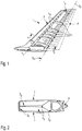
- Fig. 1 shows the typical structure of a tail T or vertical stabilizer of an aircraft in a schematic perspective view.
- the tail T includes a central box structure T B , which is shown in cross-section in Fig. 2 .
- a forward side of this central box structure T B is provided with an aerodynamic fairing F to form a leading edge of the vertical stabilizer T and a series of hinge arms H are provided along a trailing side of the box structure T B for the attachment of a rudder component R, which is then pivotable about the pivot axis X R for controlling aircraft direction in flight.
- a rudder component R which is then pivotable about the pivot axis X R for controlling aircraft direction in flight.
- the box structure T B of the tail includes a front spar S F , frame ribs F R , a rear spar S R to which the rudder hinge arms H are mounted, and outer panel members 1, which form a skin K or fairing over the box structure T B .
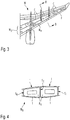
- Fig. 3 shows a wing W, a part of which is shown in cross-section in drawing Fig. 4 in a direction of arrows B-B.
- the wing W has a central box structure W B having front and rear spars S F , S R for respectively supporting a leading edge fairing F and trailing edge control surfaces C, such as flaps and ailerons.
- panel members 1 are provided on upper and lower sides of the box structure W B of the wing W, also supported by central spars S c of the box structure W B to form a skin K (e.g. aerodynamic skin) of the wing structure.
- a skin K e.g. aerodynamic skin
- a lenticular form i.e. a lens shape
- the benefits of this lenticular panel form are described, for example, in the International patent application no. WO 2012/028263 A1 .
- the airframe 100 comprises a composite panel member 1, which may form a fairing F or a skin K of the airframe, and an elongate structural member 2 attached at one side (i.e. at an internal side) of the panel member 1.
- the panel member 1 has a sandwich structure 3 comprising a first outer layer 4 on a first side 5 (i.e. on an external or aerodynamic side) of the panel 1, and a second outer layer 6 on a second side 7 (i.e. the internal side) of the panel member 1.
- a core 8 is arranged as a layer between, and coextensive with, the first and second layers 4, 6.
- the first and second outer layers 4, 6 of the sandwich are relatively thin, while the core 8 is relatively thick.
- the panel member 1 further includes a plurality of support elements 9, of which only a single one is illustrated here in cross-section.
- the support elements 9 are elongate and are arranged generally parallel and spaced apart from one another at regular intervals across a breadth of the panel member 1, only a portion of which is shown in Fig. 5 .
- These support elements 9 extend transversely across the panel member 1 within the core 8 generally parallel to the internal and external outer layers 4, 6.
- each support element 9 has a cross-sectional profile that is I-shaped and thus forms a transverse stiffener.
- each support element 9 is comprised of a copper mesh in its I-shaped cross-sectional profile.
- the first outer layer 4 at the external side of the panel member 1 is comprised of a composite material, such as carbon fibre-reinforced polymer (CFRP), but preferably includes an electrically conducting metal foil on or over an outer surface of that layer 4.
- the second outer layer 6 at the internal side of the panel 1 is comprised of a composite material, such as carbon fibre-reinforced polymer (CFRP). This second layer 6, however, will typically not include a conducting foil.
- the generally I-shaped support element 9 has flanges 10 at opposite sides of a central web 11. To the external side 5 of the panel member, these flanges 10 are in intimate contact with the first CFRP layer 4. To the opposite, internal side 7 of the panel 1, the flanges 10 of each support element 9 are in intimate contact with the second CFRP layer 6 of the panel. In this way, each of the support elements 9 in the core 8 spans a full width 12 of the core 8 from the first layer 4 at the external side 5 of the panel member 1 to the second layer 6 at the internal side 7 of the panel. Each support element 9 thereby forms an electrical conductor extending both transversely through the panel 1 as well as across a full width 12 of the panel.
- the support elements 9 are provided with a coating or covering 13 of fibre-reinforced polymer FRP materials, such CFRP.
- This coating 13 may, for example, be in the form of a CFRP prepreg applied to the support element 9 before it is inserted or embedded into the foam core 8.
- prepreg sheets will typically have a sticky or tacky consistency which enable them to readily adhere and bond both to the copper mesh support element 9 as well as to the foam material of the core 8 when the support element 9 is inserted or embedded in that core layer.
- dry fibre material may be used, e.g. as a woven fabric or a nonwoven fabric.
- a binder material will typically also be used to ensure a good adherence to both the copper mesh of the support element 9 and the solid foam material of the core 8.
- the binder will typically be activated by heating or curing to effect the adherence or bonding. Once cured, the coating or covering 13 will also render the support element 9 stiffer or more rigid to structurally reinforce the panel 1.
- the structural member 2 (e.g. such as a frame rib F R ) of the airframe 100 is attached to the panel member 1 in substantial alignment with the support element 9. This attachment may be, for example, by means of traditional fastening elements 14, such as rivets or bolts (e.g. Hi-Lok).
- the structural member 2 in this embodiment also has an I-shaped cross-sectional profile, with flanges 15 being essentially aligned with the flanges 10 of the support element 9 at the internal side 7 of the panel member 1.
- a metallic powder such as copper powder may be added over the area at which the flanges 10 of the support elements 9 abut and/or contact the respective first and second layers 4, 6.
- the composite panel member 1 integrated within the airframe 100 as seen in Fig. 5 provides for dramatically enhanced safety and structural integrity in the skin K of an aircraft in the event of a lightning strike.
- the panel member 1 of the invention is able to conduct and effectively distribute the electrical discharge from a lightning strike rapidly throughout the panel so that the energy of the lightning strike is not concentrated or focused solely in the vicinity of the strike itself. That is, the metal foil in the first outer layer 4 distributes energy of the lightning to the support elements 9 extending throughout the panel 1. By distributing the electrical energy over a large area, damage to the panel and/or the airframe structure as a whole can be substantially avoided.
- a significant further advantage of the configuration of this panel member 1 is that formation of a crack 16 in the core 8 can be significantly inhibited. That is, even if a crack 16 were to form in the solid foam of the core layer 8 (e.g. due to a lightning strike), the fact that the support elements 9 span a full width 12 of the core layer 8 between the first and second layers 4, 6 of the panel 1 and extend continuously in a transverse direction across the core 8 results in those mesh support elements 9 effectively forming barriers through the panel 1 which prevent propagation of that crack 16.
- FIG. 6 of the drawings another preferred embodiment of an airframe structure 100 of the invention is shown in cross-sectional view.
- the general principles of the arrangement and configuration of the parts of panel member 1 in Fig. 6 are substantially the same as for Fig. 5 , such that the same reference numerals identify corresponding or like parts, the description of which will be omitted in the same level of detail to avoid repetition.
- the support elements 9, which are again elongate and extend in a generally transverse direction within the foam core 8 in the sandwich structure 3 of the panel 1, have an inverted T-shape in cross-sectional profile.
- the flanges 10 of the profile of the support elements 9 are again in contact with the first CFRP layer 4 at the first or external side 5 of the panel member.
- the web 11 of that profile projects through a plane of the second outer layer 6 at the internal side 7 of the panel member 1.
- portions 17 of the second layer 6 may be extended through a 90 degree bend to sheath or cover the projecting web 11 of each copper mesh support element 9 at that internal side 7 of the panel.
- the T-shaped copper mesh support elements 9 are again covered or coated with CFRP material 13 to enhance the bonding to the foam material of the core 8.
- the structural member 2 also has a T-shaped cross-sectional profile and is secured to the panel member via fastening elements 16 such as rivets or bolts at an interface formed by the overlap with a web of the respective T-shaped profiles.
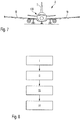
- FIG. 7 a schematic illustration is shown of an aircraft A having an airframe 100, including the tail T and the wings W as well as the fuselage, in which one or more panel members 1 according to an embodiment of the invention, for example, as described with reference to Fig. 5 or Fig. 6 , is incorporated.
- Fig. 8 of the drawings a flow diagram is shown that schematically illustrates the steps in a method of forming a panel member 1 according to the embodiments of the invention described above with respect to Figs. 5 and 6 .
- the first box I of Fig. 8 represents the step of providing a core layer 8, e.g. of a solid or hard foam, for a composite sandwich structure 3.
- the second box II represents the step of providing at least one elongate support element 9 configured as an electrical conductor in the core layer 8. This will typically include forming at least one recess in the foam core 8 for receiving a respective support element 9, and then inserting or embedding the respective support element 9 in that recess.
- the third box III represents the step of arranging the core layer 8 between first and second fibre reinforcement sheet layers in a sandwich arrangement 3, such that the at least one support element 9 extends within the core layer 8 substantially parallel to these first and second sheet layers 4, 6.
- the fourth box IV in Fig. 8 then represents the step of impregnating the sandwich arrangement 3, and especially the first and second fibre reinforcement sheet layers, with a polymer resin.
- the step of impregnating the sandwich arrangement 3 may comprise resin infusion, e.g. via a vacuum bagging or a resin transfer moulding (RTM) technique.
- the method typically also includes a step of curing the polymer resin, e.g. by heating the impregnated the sandwich arrangement 3 over a period of time, taking care to avoid residual stresses being generated or occurring in the composite sandwich structure.
- the terms “comprise”, “comprising”, “include”, “including”, “contain”, “containing”, “have”, “having”, and any variations thereof, are intended to be understood in an inclusive (i.e. non-exclusive) sense, such that the process, method, device, apparatus or system described herein is not limited to those features or parts or elements or steps recited but may include other elements, features, parts or steps not expressly listed or inherent to such process, method, article, or apparatus.
- the terms “a” and “an” used herein are intended to be understood as meaning one or more unless explicitly stated otherwise.
- the terms “first”, “second”, “third”, etc. are used merely as labels, and are not intended to impose numerical requirements on or to establish a certain ranking of importance of their objects.
- each of the first and second outer layers (4, 6) is comprised of a composite material, desirably a fibre-reinforced composite, more preferably a fibre-reinforced polymer composite, and wherein the core layer (8) is preferably a relatively low density material, such as a hard foam having an open-cell or closed-cell structure, and preferably comprised of a synthetic material, such as a polymer.
- each of the first and second outer layers (4, 6) is comprised of a composite material, preferably a fibre-reinforced composite, more preferably a fibre-reinforced polymer composite, wherein the core (8) is preferably a relatively low density material, such as a hard polymer foam, and wherein the structural member (2) is comprised of a composite material, such as a fibre-reinforced polymer composite.
Landscapes
- Engineering & Computer Science (AREA)
- Aviation & Aerospace Engineering (AREA)
- Mechanical Engineering (AREA)
- Remote Sensing (AREA)
- Laminated Bodies (AREA)
Abstract
Description
- This invention relates to a panel member for an airframe or fuselage structure, as well as to an airframe or fuselage structure for an aircraft or spacecraft incorporating such a panel member.
- The panel member of the invention is especially suitable for use in a fairing, skin or covering of an airframe or fuselage structure, such as in a tail or a vertical stabilizer of an aircraft or spacecraft, and it will be convenient to describe the invention in this exemplary context. However, it will be appreciated that the present invention is not limited to this application, but may be used in a variety of structures, and particularly vehicle structures, such as trains, automobiles, trucks, and ships. Thus, the invention may be suitable for a range of nautical, aeronautical and automotive applications.
- The use of composite materials in the design of aircraft and spacecraft today is becoming increasingly prevalent due to the light-weight and relatively high-strength properties achievable with those materials, among which fibre-reinforced polymer composites, such as carbon fibre reinforced polymers (CFRP), are especially preferred. The physical properties of composite materials are not always advantageous, however, in particular aeronautical applications. For example, many fibre reinforced composites have a low conductivity and relatively high resistance to both thermal and electrical energy. Thus, when used in an airframe structure at a location susceptible to lightning strikes, such as an upper region of the tail (or vertical stabilizer) or in distal tip regions of the wings, a CRFP composite material, for example, may not dissipate the energy of a lightning strike as effectively as conventional aluminium alloys. One area that has been identified as being of particular interest in development of enhanced structural integrity and lightning strike protection is in the area of composite panels, and especially panels having a laminated or composite sandwich structure, which are designed for use in a fairing, skin or covering of an airframe or fuselage.
- It is therefore an object of the present invention to provide a new and improved panel member that address one or more of the issues discussed above. In particular, it would be useful to provide a new panel member, especially for an airframe or fuselage structure, which is designed for enhanced protection in the event of a lightning strike.
- In accordance with this invention, a panel member for use in an airframe or fuselage structure having the features set out in
claim 1 is provided. Furthermore, in accordance with this invention, a vehicle body structure as recited inclaim 10, such as an airframe or fuselage structure, is provided. In addition, a vehicle, such as an aircraft or a spacecraft as recited inclaim 15, may also be provided. Various preferred features are recited in the dependent claims. - According to one aspect, therefore, the invention provides a composite panel member for an airframe of an aircraft or a spacecraft. The panel member has a laminated or sandwich structure comprising: a first outer layer which extends over a first side of the panel member, a second outer layer which extends over a second side of the panel member, and a core layer between the first and second outer layers. At least one support element is provided in the core layer and extends within the core layer substantially parallel to the first and second outer layers and is configured as an electrical conductor. Preferably, the at least one support element also at least partially spans or extends over a width of the core layer between the first and second outer layers.
- In this regard, the at least one support element in the core layer is designed to "support" or protect the laminated or sandwich structure of the panel member by conducting and distributing electrical energy away from a lightning strike, e.g. occurring at an external side of the panel member, through the core layer and over an area of the panel. Such a distribution of the electrical energy thus dissipates the intensity of the strike at the point of impact and so protects the laminated or sandwich structure of the panel at that location. Further, in a preferred embodiment, the at least one support element provided in the core may be designed to provide structural "support" or reinforcement to the laminated or sandwich structure of the panel member. In this way, the at least one support element can also be designed to protect or reinforce the panel structure panel, which may also be advantageous in the event of a lightning strike. Thus, it will be appreciated that the term "support" in respect of the feature of the "at least one support element" may be understood in the context of protection (i.e. physical protection) and/or structural reinforcement. In this way, the at least one "support element" referenced herein may also be considered to be a "protector element" or an "energy distributor element", and/or a "reinforcement element".
- Regarding the first and second "outer" layers of the sandwich structure, it will be appreciated that these layers need not necessarily form or constitute outermost layers of the panel member, but that the term "outer" in this sense rather refers to the position of these first and second layers on opposite outer sides of the core layer of the laminated or sandwich structure. Thus, additional outer layers may also be provided on the first and/or second layers.
- In a preferred embodiment, the at least one support element spans a full width of the core layer from the first outer layer to the second outer layer. In other words, considered in a plane of a cross-section taken through the laminated or sandwich structure from the first side to the second side of the panel member, the at least one support element preferably spans the full width of the core layer. As a consequence, the at least one support element may be electrically conductive across the full width of the core layer between the first and second outer layers and/or across the full cross-sectional width of the panel member. That is, the at least one support element may be configured to conduct electrically between the first side and the second side of the panel member. To this end, each support element preferably includes or is comprised of a metal, such as copper or aluminium. In particular, the at least one support element is preferably comprised of a metallic mesh or screen, or may include a metallic foil.
- In a preferred embodiment, the at least one support element is elongate and extends substantially continuously within the core in a direction substantially parallel to the first and second outer layers, and preferably across a full expanse of the panel member. The at least one support element preferably also spans the full (cross-sectional) width of the core layer over its entire length or longitudinal extent. As a result, the at least one support element may form or create a barrier across the width of the core layer to the propagation of any cracks which may arise in this part of the laminated or sandwich structure of the composite panel member. It will be appreciated that the cross-sectional width of the core layer and/or of the panel member itself may vary over an extent or expanse of the panel member (i.e. over an extent or expanse of the first side or the second side). Accordingly, a size or dimension of the at least one support element in its cross-sectional profile may also vary over its length. In this context, in a particularly preferred embodiment, the at least one support element has a cross-section or profile transverse to its longitudinal axis that is I-shaped, T-shaped, L-shaped or Z-shaped. Thus, each support element may be configured to act as, or form, a structural reinforcement in the panel member.
- In a preferred embodiment of the invention, the panel member includes a plurality of the support elements within the core layer. The plurality of support elements are typically spaced apart from one another at regular intervals and are desirably arranged to extend substantially parallel to one another. In this way, the support elements may extend over a large area of the panel member. In a particularly preferred embodiment, each of the plurality of support elements may be electrically connected with one another. The electrical energy transmitted to one support element may then be conducted to other support elements in the panel member. For example, the plurality of support elements may be arranged in parallel with one another running in two directions, and optionally connected with one another at points of intersection, thereby forming a grid of support elements extending within the core layer. In this way, the support elements may cover substantially an entire area of the panel member.
- As noted at the outset, the present invention is especially concerned with a panel member having a laminated or sandwich structure comprising composite materials. In a particularly preferred embodiment of the invention, therefore, each of the first and second outer layers is comprised of a composite material, and preferably a fibre-reinforced polymer material like a glass fibre reinforced polymer (GFRP) or carbon fibre-reinforced polymer (CFRP). In this connection, the fibres may be selected from the group consisting of glass, carbon, and aramid fibres. The polymer matrix material may be selected from the group consisting of epoxy, polyester, vinyl ester and nylon resins. Furthermore, the core layer is preferably a relatively low density material, such as a foam (e.g. a solid foam or a hard foam, which may have an open-cell or closed-cell structure), and is preferably comprised of a synthetic material, such as a polymer. Synthetic foams, like polyvinylchloride, polyurethane, polyethylene or polystyrene foams, as well as syntactic foams or metallic foams may be contemplated as a material of the core layer. In this regard, a sandwich-structured composite is typically fabricated with the first and second outer layers forming two thin but stiff skins to a lightweight but relatively thick core. The core material is typically a lower strength material than the outer layers, but its higher thickness provides the sandwich structure with a relatively high bending stiffness and yet with an overall relatively low density.
- In a preferred embodiment, the at least one support element is fully embedded within the core layer of the laminated or sandwich structure. In this way, each support element may be in contact with and/or connected to either or both of the first and second outer layers. In one particular embodiment or configuration, the at least one support element may be in contact with and/or connected to the first outer layer, span a full width of the core layer and also project through the second outer layer to or beyond the second side of the panel member. Preferably, either or both of the first and second outer layers of the laminated or sandwich structure includes an electrically conductive sheet or foil, which is preferably substantially coextensive therewith. In this way, each said at least one support element may be in electrical conducting contact with such a sheet or foil in either or both of the first and second layers of the panel member.
- In a particularly preferred embodiment of the invention, the at least one support element is provided with a covering or a coating, which may enhance its bonding to and/or integration in the core layer of the panel member. For example, the at least one support element may include a polymer covering or coating, or an FRP covering or coating for improved bonding or adhesion within the core of the laminated or sandwich structure. Where each said at least one support element is comprised a metal, e.g. of a copper mesh, the support element may optionally be covered or coated with a laminate, e.g. a prepreg. This coating or covering may thus not only enhance the bonding to any one of the core and/or the outer layers of the panel, but may also enhance or improve the structural properties of the support element. That is, a relatively soft and ductile copper mesh may be stiffened via a prepreg or FRP coating or covering to better reinforce the panel member.
- In a particularly preferred embodiment of the invention, the panel member may include an electrically conducting additive, e.g. to the core layer and/or to either or both of the first and second layers, to enhance electrical conductivity through the panel member. For example, the conducting additive may include metallic particles or metallic powder, such as copper powder, which may be added to the panel member adjacent each support member.
- Expressed in another manner, a broad aspect of the invention provides a composite panel for an airframe of an aircraft or spacecraft. The composite panel has a sandwich or laminated structure comprising a first layer, a second layer, and a core between the first and second layers. At least one support element or protector element is provided or arranged within the core such that it extends within the core substantially parallel to the first and second layers and is configured for electrical conduction through the core.
- According to a further aspect, the present invention provides a method of producing a composite panel member for a vehicle body structure, such as an airframe or fuselage structure for an aircraft or spacecraft, the method comprising:
- providing a core layer, preferably of a solid or hard foam, for a composite sandwich structure;
- providing at least one elongate support element in the core layer, the at least one support element being configured as an electrical conductor;
- arranging the core layer between first and second fibre reinforcement sheet layers in a sandwich arrangement, such that the at least one support element extends within the core layer substantially parallel to the first and second sheet layers; and
- impregnating the sandwich arrangement, and particularly the first and second fibre reinforcement sheet layers, with a polymer resin.
- In a preferred embodiment, the step of providing at least one elongate support element in the core layer includes forming at least one recess in the core layer (e.g. in the solid or hard foam) for receiving a respective support element, and then inserting or embedding the respective support element in that recess. The at least one recess is desirably formed with a geometry corresponding to a shape of the support element. The step of impregnating the sandwich arrangement preferably includes resin infusion, e.g. via a vacuum bagging or a resin transfer moulding (RTM) technique, such as vacuum-assisted resin transfer moulding (VARTM). The method will typically also include the step of curing the polymer resin after the impregnating step. In this regard, care needs to be taken in the impregnating and curing steps to avoid residual stresses forming in the composite sandwich structure. The materials of both the support elements and the core may play a significant role here. For example, whereas a hard foam core will tend to contract upon cooling after curing, a prepreg or FRP coating or covering over the support elements typically has a lower coefficient of thermal expansion and will largely unaffected by the cooling, which can lead to residual stresses. A copper support element under the prepreg or FRP coating or covering, on the other hand, will have a relatively high coefficient of thermal expansion, which in turn may counteract the tendency of the prepreg or FRP coating or covering not to deform much under the temperature differential upon cooling, especially where the coating or covering is quite thin.
- According to a further aspect, the present invention provides a vehicle body structure, especially an airframe, fuselage or box structure for an aircraft or spacecraft, comprising:
- a composite panel with a laminated or sandwich structure comprising: a first layer which extends over a first side of the panel member, a second layer which extends over a second side of the panel member, a core layer between the first and second layers, and at least one support element provided in the core layer and extending generally parallel to the first and second layers; and
- an elongate structural member attached to the panel member at the second side thereof, the elongate structural member being substantially aligned with and/or connected with the at least one support element;
- wherein the at least one support element is configured as or forms an electrical conductor between the first side of the panel member and the elongate structural element at the second side of the panel member.
- In a preferred embodiment, the elongate structural member is connected with the at least one support element at the second side of the panel member, preferably at an interface that is substantially parallel to the second layer. In this regard, the elongate structural member desirably has a cross-section or profile transverse to its longitudinal axis that is I-shaped, T-shaped, L-shaped or Z-shaped, such that a flange of its profile is arranged parallel to the second layer at the second side of the panel. In a modified preferred embodiment, however, the elongate structural member may be connected with the support element at an interface that is substantially perpendicular to the second outer layer. In this modified embodiment, for example, the at least one support element may project through or beyond the second outer layer to the second side of the panel member for connection to a web in the profile of the elongate structural member.
- In a preferred embodiment, the at least one support element is elongate and extends substantially continuously within the core in the direction substantially parallel to the first and second outer layers. Furthermore, considered in a transverse cross-section, the at least one support element spans a width of the core between the first and second layers such that it may form a barrier to crack propagation in the core.
- As already discussed in detail, the panel member desirably includes a plurality of the said at least one support element within the core. The plurality of support elements may be spaced apart from one another at intervals and are desirably arranged to extend substantially parallel to one another. The plurality of support elements may also be connected with one another electrically.
- Further, as also noted above, the panel member is preferably comprised of composite materials. In a particularly preferred embodiment, therefore, each of the first and second layers is comprised of a composite material, such as a fibre-reinforced composite, like GFRP or CFRP. The core is preferably formed of a relatively low density material, such as a solid foam or hard foam, and is preferably comprised of a polymer material. The structural member, also, may be comprised of a composite material, such as a fibre-reinforced polymer (FRP) material, though the structural member could also be comprised of a metal or metal alloy, such as an aluminium or titanium alloy.
- According to a further aspect, the present invention provides a vehicle, such as an aircraft or spacecraft, having a body structure (e.g. an airframe or fuselage structure) according to any one of the embodiments described above.
- For a more complete understanding of the present invention and the advantages thereof, exemplary embodiments of the invention are explained in more detail in the following description with reference to the accompanying drawings, in which like reference characters designate like parts and in which:
- Fig. 1
- is a schematic view of the structure of a tail or vertical stabilizer of an aircraft;
- Fig. 2
- is a cross-sectional view of the tail or vertical stabilizer of
Fig. 1 in a direction of arrows A-A; - Fig. 3
- is a schematic view of the structure of a wing of an aircraft;
- Fig. 4
- is a cross-sectional view of the wing of
Fig. 3 in the direction of arrows B-B; - Fig. 5
- is a cross-sectional view of a panel member of one preferred embodiment of the invention incorporated in an airframe structure;
- Fig. 6
- is a cross-section view of a panel member according to another preferred embodiment of the invention shown incorporated in an airframe structure;
- Fig. 7
- is a schematic illustration of an aircraft in which one or more panel member according to an embodiment of the invention is installed; and
- Fig. 8
- is a flow diagram which schematically illustrates a method according to an embodiment of the invention.
- The accompanying drawings are included to provide a further understanding of the present invention and are incorporated in and constitute a part of this specification. The drawings illustrate particular embodiments of the invention and together with the description serve to explain the principles of the invention. Other embodiments of the invention and many of the attendant advantages of the invention will be readily appreciated as they become better understood with reference to the following detailed description.
- It will be appreciated that common and well understood elements that may be useful or necessary in a commercially feasible embodiment are not necessarily depicted in order to facilitate a more abstracted view of the embodiments. The elements of the drawings are not necessarily illustrated to scale relative to each other. It will further be appreciated that certain actions and/or steps in an embodiment of a method may be described or depicted in a particular order of occurrences while those skilled in the art will understand that such specificity with respect to sequence is not necessarily required. It will also be understood that the terms and expressions used in the present specification have the ordinary meaning as is accorded to such terms and expressions with respect to their corresponding respective areas of inquiry and study, except where specific meanings have otherwise been set forth herein.
- With reference firstly to
Figs. 1 to 4 of the drawings, parts of an airframe of an aircraft are illustrated.Fig. 1 , for example, shows the typical structure of a tail T or vertical stabilizer of an aircraft in a schematic perspective view. In this regard, the tail T includes a central box structure TB, which is shown in cross-section inFig. 2 . A forward side of this central box structure TB is provided with an aerodynamic fairing F to form a leading edge of the vertical stabilizer T and a series of hinge arms H are provided along a trailing side of the box structure TB for the attachment of a rudder component R, which is then pivotable about the pivot axis XR for controlling aircraft direction in flight. With reference toFig. 2 , the box structure TB of the tail includes a front spar SF, frame ribs FR, a rear spar SR to which the rudder hinge arms H are mounted, andouter panel members 1, which form a skin K or fairing over the box structure TB. - Similarly,
Fig. 3 shows a wing W, a part of which is shown in cross-section in drawingFig. 4 in a direction of arrows B-B. Again, the wing W has a central box structure WB having front and rear spars SF, SR for respectively supporting a leading edge fairing F and trailing edge control surfaces C, such as flaps and ailerons. Again,panel members 1 are provided on upper and lower sides of the box structure WB of the wing W, also supported by central spars Sc of the box structure WB to form a skin K (e.g. aerodynamic skin) of the wing structure. It will be appreciated fromFig. 2 andFig. 4 that thepanel members 1 mounted on the box structures TB, WB of the tail T and the wing W, respectively, have a lenticular form (i.e. a lens shape) in cross-section. The benefits of this lenticular panel form are described, for example, in the International patent application no.WO 2012/028263 A1 . - The design or configuration of the
panel members 1 according to embodiments of the invention will now be further described with reference toFigs. 5 and 6 of the drawings, as well as their incorporation in an airframe of an aircraft, such as in the wing structure W and/or the tail or vertical stabilizer structure T ofFigs. 1 to 4 . - Referring now to
Fig. 5 , therefore, anairframe structure 100 according to a preferred embodiment is illustrated which may be directly applicable to the vertical stabilizer T or wing structure W shown inFigs. 1 to 4 . Theairframe 100 comprises acomposite panel member 1, which may form a fairing F or a skin K of the airframe, and an elongate structural member 2 attached at one side (i.e. at an internal side) of thepanel member 1. Thepanel member 1 has asandwich structure 3 comprising a first outer layer 4 on a first side 5 (i.e. on an external or aerodynamic side) of thepanel 1, and a secondouter layer 6 on a second side 7 (i.e. the internal side) of thepanel member 1. Further, a core 8 is arranged as a layer between, and coextensive with, the first andsecond layers 4, 6. As is typical in composite sandwich structures, the first and secondouter layers 4, 6 of the sandwich are relatively thin, while the core 8 is relatively thick. - With reference to
Fig. 5 , thepanel member 1 further includes a plurality of support elements 9, of which only a single one is illustrated here in cross-section. The support elements 9 are elongate and are arranged generally parallel and spaced apart from one another at regular intervals across a breadth of thepanel member 1, only a portion of which is shown inFig. 5 . These support elements 9 extend transversely across thepanel member 1 within the core 8 generally parallel to the internal and externalouter layers 4, 6. As can be seen, each support element 9 has a cross-sectional profile that is I-shaped and thus forms a transverse stiffener. Furthermore, each support element 9 is comprised of a copper mesh in its I-shaped cross-sectional profile. The first outer layer 4 at the external side of thepanel member 1 is comprised of a composite material, such as carbon fibre-reinforced polymer (CFRP), but preferably includes an electrically conducting metal foil on or over an outer surface of that layer 4. In a similar manner, the secondouter layer 6 at the internal side of thepanel 1 is comprised of a composite material, such as carbon fibre-reinforced polymer (CFRP). Thissecond layer 6, however, will typically not include a conducting foil. - As is apparent from
Fig. 5 of the drawings, the generally I-shaped support element 9 hasflanges 10 at opposite sides of acentral web 11. To the external side 5 of the panel member, theseflanges 10 are in intimate contact with the first CFRP layer 4. To the opposite, internal side 7 of thepanel 1, theflanges 10 of each support element 9 are in intimate contact with thesecond CFRP layer 6 of the panel. In this way, each of the support elements 9 in the core 8 spans afull width 12 of the core 8 from the first layer 4 at the external side 5 of thepanel member 1 to thesecond layer 6 at the internal side 7 of the panel. Each support element 9 thereby forms an electrical conductor extending both transversely through thepanel 1 as well as across afull width 12 of the panel. - In order to enhance adhesion or bonding between the solid or hard foam material of the core layer 8 and the copper mesh of each support element 9, the support elements 9 are provided with a coating or covering 13 of fibre-reinforced polymer FRP materials, such CFRP. This
coating 13 may, for example, be in the form of a CFRP prepreg applied to the support element 9 before it is inserted or embedded into the foam core 8. In this regard, such prepreg sheets will typically have a sticky or tacky consistency which enable them to readily adhere and bond both to the copper mesh support element 9 as well as to the foam material of the core 8 when the support element 9 is inserted or embedded in that core layer. Alternatively, dry fibre material may be used, e.g. as a woven fabric or a nonwoven fabric. In that case, a binder material will typically also be used to ensure a good adherence to both the copper mesh of the support element 9 and the solid foam material of the core 8. The binder will typically be activated by heating or curing to effect the adherence or bonding. Once cured, the coating or covering 13 will also render the support element 9 stiffer or more rigid to structurally reinforce thepanel 1. - The structural member 2 (e.g. such as a frame rib FR) of the
airframe 100 is attached to thepanel member 1 in substantial alignment with the support element 9. This attachment may be, for example, by means oftraditional fastening elements 14, such as rivets or bolts (e.g. Hi-Lok). The structural member 2 in this embodiment also has an I-shaped cross-sectional profile, withflanges 15 being essentially aligned with theflanges 10 of the support element 9 at the internal side 7 of thepanel member 1. To enhance the electrical conductivity between thecopper mesh flanges 10 of each support element 9 and the respective first and secondouter layers 4, 6 of thesandwich structure 3 on opposite sides of the core 8, a metallic powder (not shown) such as copper powder may be added over the area at which theflanges 10 of the support elements 9 abut and/or contact the respective first andsecond layers 4, 6. - In this embodiment, therefore, the
composite panel member 1 integrated within theairframe 100 as seen inFig. 5 provides for dramatically enhanced safety and structural integrity in the skin K of an aircraft in the event of a lightning strike. In particular, thepanel member 1 of the invention is able to conduct and effectively distribute the electrical discharge from a lightning strike rapidly throughout the panel so that the energy of the lightning strike is not concentrated or focused solely in the vicinity of the strike itself. That is, the metal foil in the first outer layer 4 distributes energy of the lightning to the support elements 9 extending throughout thepanel 1. By distributing the electrical energy over a large area, damage to the panel and/or the airframe structure as a whole can be substantially avoided. - A significant further advantage of the configuration of this
panel member 1 is that formation of acrack 16 in the core 8 can be significantly inhibited. That is, even if acrack 16 were to form in the solid foam of the core layer 8 (e.g. due to a lightning strike), the fact that the support elements 9 span afull width 12 of the core layer 8 between the first andsecond layers 4, 6 of thepanel 1 and extend continuously in a transverse direction across the core 8 results in those mesh support elements 9 effectively forming barriers through thepanel 1 which prevent propagation of thatcrack 16. - Referring now to
Fig. 6 of the drawings, another preferred embodiment of anairframe structure 100 of the invention is shown in cross-sectional view. The general principles of the arrangement and configuration of the parts ofpanel member 1 inFig. 6 are substantially the same as forFig. 5 , such that the same reference numerals identify corresponding or like parts, the description of which will be omitted in the same level of detail to avoid repetition. - A clear difference in this embodiment, however, is that the support elements 9, which are again elongate and extend in a generally transverse direction within the foam core 8 in the
sandwich structure 3 of thepanel 1, have an inverted T-shape in cross-sectional profile. Theflanges 10 of the profile of the support elements 9 are again in contact with the first CFRP layer 4 at the first or external side 5 of the panel member. Theweb 11 of that profile, however, projects through a plane of the secondouter layer 6 at the internal side 7 of thepanel member 1. Thus,portions 17 of thesecond layer 6 may be extended through a 90 degree bend to sheath or cover the projectingweb 11 of each copper mesh support element 9 at that internal side 7 of the panel. Within the foam core 8, the T-shaped copper mesh support elements 9 are again covered or coated withCFRP material 13 to enhance the bonding to the foam material of the core 8. In this case, the structural member 2 also has a T-shaped cross-sectional profile and is secured to the panel member viafastening elements 16 such as rivets or bolts at an interface formed by the overlap with a web of the respective T-shaped profiles. - With reference to
Fig. 7 , a schematic illustration is shown of an aircraft A having anairframe 100, including the tail T and the wings W as well as the fuselage, in which one ormore panel members 1 according to an embodiment of the invention, for example, as described with reference toFig. 5 or Fig. 6 , is incorporated. - Referring now to
Fig. 8 of the drawings, a flow diagram is shown that schematically illustrates the steps in a method of forming apanel member 1 according to the embodiments of the invention described above with respect toFigs. 5 and 6 . In this regard, the first box I ofFig. 8 represents the step of providing a core layer 8, e.g. of a solid or hard foam, for acomposite sandwich structure 3. The second box II represents the step of providing at least one elongate support element 9 configured as an electrical conductor in the core layer 8. This will typically include forming at least one recess in the foam core 8 for receiving a respective support element 9, and then inserting or embedding the respective support element 9 in that recess. The third box III represents the step of arranging the core layer 8 between first and second fibre reinforcement sheet layers in asandwich arrangement 3, such that the at least one support element 9 extends within the core layer 8 substantially parallel to these first and second sheet layers 4, 6. The fourth box IV inFig. 8 then represents the step of impregnating thesandwich arrangement 3, and especially the first and second fibre reinforcement sheet layers, with a polymer resin. The step of impregnating thesandwich arrangement 3 may comprise resin infusion, e.g. via a vacuum bagging or a resin transfer moulding (RTM) technique. After the impregnating step, the method typically also includes a step of curing the polymer resin, e.g. by heating the impregnated thesandwich arrangement 3 over a period of time, taking care to avoid residual stresses being generated or occurring in the composite sandwich structure. - Although specific embodiments of the invention have been illustrated and described herein, it will be appreciated by those of ordinary skill in the art that a variety of alternate and/or equivalent implementations exist. It should be appreciated that the exemplary embodiment or exemplary embodiments are only examples, and are not intended to limit the scope, applicability, or configuration in any way. Rather, the foregoing summary and detailed description will provide those skilled in the art with a convenient road map for implementing at least one exemplary embodiment, it being understood that various changes may be made in the function and arrangement of elements described in an exemplary embodiment without departing from the scope as set forth in the appended claims and their legal equivalents. Generally, this application is intended to cover any adaptations or variations of the specific embodiments discussed herein.
- In this document, the terms "comprise", "comprising", "include", "including", "contain", "containing", "have", "having", and any variations thereof, are intended to be understood in an inclusive (i.e. non-exclusive) sense, such that the process, method, device, apparatus or system described herein is not limited to those features or parts or elements or steps recited but may include other elements, features, parts or steps not expressly listed or inherent to such process, method, article, or apparatus. Furthermore, the terms "a" and "an" used herein are intended to be understood as meaning one or more unless explicitly stated otherwise. Moreover, the terms "first", "second", "third", etc. are used merely as labels, and are not intended to impose numerical requirements on or to establish a certain ranking of importance of their objects.
- The application further comprises the following embodiments:
- A composite panel member (1) for an airframe (100) of an aircraft or spacecraft, the composite panel member (1) having a laminated or sandwich structure (3) comprising:
- a first outer layer (4) extending over a first side (5) of the panel member (1);
- a second outer layer (6) extending over a second side (7) of the panel member (1);
- a core layer (8) between the first and second outer layers (4, 6); and
- A panel member (1) according to
embodiment 1, wherein the at least one support element (9) is elongate and extends substantially continuously within the core (8) in the direction substantially parallel to the first and second outer layers (4, 6). - A panel member (1) according to
embodiment 1 or embodiment 2, wherein, in a plane of a cross-section taken through the laminated or sandwich structure (3) from the first side (5) to the second side (7) of the panel member (1), the at least one support element (9) spans a full width (12) of the core layer (8) from the first outer layer (4) to the second outer layer (6) to form a barrier through the core layer (8). - A panel member (1) according to any of
embodiments 1 to 3, wherein the at least one support element (9) is adapted for electrical conduction between the first side and the second side of the panel member (1), and/or wherein the at least one support element (9) is preferably comprised of a metallic mesh or includes a metallic foil. - A panel member (1) according to any of
embodiments 1 to 4, wherein the at least one support element (9) includes a covering or a coating (13); the covering or coating (13) preferably comprising a prepreg. - A panel member (1) according to any of
embodiments 1 to 5, wherein each of the first and second outer layers (4, 6) is comprised of a composite material, desirably a fibre-reinforced composite, more preferably a fibre-reinforced polymer composite, and wherein the core layer (8) is preferably a relatively low density material, such as a hard foam having an open-cell or closed-cell structure, and preferably comprised of a synthetic material, such as a polymer. - A panel member (1) according to any of
embodiments 1 to 6, wherein the at least one support element (9) is fully embedded within the core layer (8) of the laminated or sandwich structure (3), the at least one support element (9) being in contact with and/or connected to either or both of the first and second outer layers (4, 6); wherein the at least one support element (9) preferably projects through the second outer layer (6) to the second side (7) of the panel member (1). - A panel member (1) according to any of
embodiments 1 to 7, wherein the at least one support element (9) has a cross-section or profile transverse to its longitudinal axis that is I-shaped, T-shaped, L-shaped or Z-shaped. - A panel member (1) according to any of
embodiments 1 to 8, wherein either or both of the first and second outer layers (4, 6) includes an electrically conductive sheet or foil which is substantially coextensive therewith. - A vehicle body structure (100), especially an airframe, fuselage or box structure for an aircraft or spacecraft, the body structure (2) comprising:
- a composite panel member (1) having a laminated or sandwich structure (3) comprising: a first layer (4) over a first side (5) of the panel member (1), a second layer (6) over a second side (7) of the panel member, a core (8) between the first and second layers (4, 6), and at least one support element (9) within the core (8), the at least one support element (8) extending generally parallel to the first and second layers (4, 6); and
- an elongate structural member (2) which is attached to the panel member (1) at the second side (7) thereof, the elongate structural member (2) being substantially aligned and/or connected with the at least one support element (9);
- wherein the at least one support element (9) forms an electrical conductor between the first side of the panel member (1) and the elongate structural element (2) at the second side of the panel member (1).
- A body structure (100) according to
embodiment 10, wherein the elongate structural member (2) is connected with the at least one support element (9) at the second side (7) of the panel member (1), preferably at an interface that is substantially parallel to the second outer layer (6), the elongate structural member (2) preferably having a cross-section or profile transverse to its longitudinal axis that is I-shaped, T-shaped, L-shaped or Z-shaped. - A body structure (100) according to
embodiment 10 orembodiment 11, wherein the elongate structural member (2) is connected with the at least one support element (9) at an interface that is substantially perpendicular to the second outer layer (5). - A body structure (100) according to any of
embodiments 10 to 12, wherein the at least one support element (9) is elongate and extends substantially continuously within the core (8) in a direction substantially parallel to the first and second outer layers (4, 6), wherein the at least one support element (9) spans a full width (12) of the core layer (8) from the first outer layer (4) to the second outer layer (6) such that it forms a barrier in the core layer (8). - A body structure (100) according to any of
embodiments 10 to 13, wherein each of the first and second outer layers (4, 6) is comprised of a composite material, preferably a fibre-reinforced composite, more preferably a fibre-reinforced polymer composite, wherein the core (8) is preferably a relatively low density material, such as a hard polymer foam, and wherein the structural member (2) is comprised of a composite material, such as a fibre-reinforced polymer composite. - An aircraft (A) or spacecraft having a panel member (1) according to any of
embodiments 1 to 9 and/or a body structure (100) according to any ofembodiments 10 to 14. -
- 1
- panel member or panel
- 2
- structural member
- 3
- sandwich structure
- 4
- first layer
- 5
- first side of panel member
- 6
- second layer
- 7
- second side of panel member
- 8
- core or core layer
- 9
- support element
- 10
- flange of support element
- 11
- central web of support element
- 12
- width of core layer
- 13
- coating or covering
- 14
- fastening elements
- 15
- flange of structural member
- 16
- crack
- 17
- portion of the second layer
- 18
- web of the structural member
- 100
- airframe
- T
- tail or vertical stabilizer
- TB
- box structure of tail
- F
- faring
- H
- hinge arms
- R
- rudder
- XR
- pivot axis
- SF
- front spar
- SR
- rear spar
- SC
- central spar
- FR
- frame ribs
- K
- skin
- W
- wing
- WB
- box structure of wing
- C
- control surfaces
- A
- aircraft
wherein the at least one support element (9) extends within the core layer (8) substantially parallel to the first and second outer layers (4, 6).
Claims (9)
- A composite panel member (1) for an airframe (100) of an aircraft or spacecraft, the composite panel member (1) having a laminated or sandwich structure (3) comprising:a first outer layer (4) extending over a first side (5) of the panel member (1);a second outer layer (6) extending over a second side (7) of the panel member (1);a core layer (8) between the first and second outer layers (4, 6); andat least one support element (8) configured as an electrical conductor and provided in the core layer (8) between the first and second outer layers (4, 6);wherein the at least one support element (9) extends within the core layer (8) substantially parallel to the first and second outer layers (4, 6).
- A panel member (1) according to claim 1, wherein the at least one support element (9) is elongate and extends substantially continuously within the core (8) in the direction substantially parallel to the first and second outer layers (4, 6).
- A panel member (1) according to claim 1 or claim 2, wherein, in a plane of a cross-section taken through the laminated or sandwich structure (3) from the first side (5) to the second side (7) of the panel member (1), the at least one support element (9) spans a full width (12) of the core layer (8) from the first outer layer (4) to the second outer layer (6) to form a barrier through the core layer (8).
- A panel member (1) according to any of claims 1 to 3, wherein the at least one support element (9) is adapted for electrical conduction between the first side and the second side of the panel member (1), and/or wherein the at least one support element (9) is preferably comprised of a metallic mesh or includes a metallic foil.
- A panel member (1) according to any of claims 1 to 4, wherein the at least one support element (9) includes a covering or a coating (13); the covering or coating (13) preferably comprising a prepreg.
- A panel member (1) according to any of claims 1 to 5, wherein each of the first and second outer layers (4, 6) is comprised of a composite material, desirably a fibre-reinforced composite, more preferably a fibre-reinforced polymer composite, and wherein the core layer (8) is preferably a relatively low density material, such as a hard foam having an open-cell or closed-cell structure, and preferably comprised of a synthetic material, such as a polymer.
- A panel member (1) according to any of claims 1 to 6, wherein the at least one support element (9) is fully embedded within the core layer (8) of the laminated or sandwich structure (3), the at least one support element (9) being in contact with and/or connected to either or both of the first and second outer layers (4, 6); wherein the at least one support element (9) preferably projects through the second outer layer (6) to the second side (7) of the panel member (1).
- A panel member (1) according to any of claims 1 to 7, wherein the at least one support element (9) has a cross-section or profile transverse to its longitudinal axis that is I-shaped, T-shaped, L-shaped or Z-shaped.
- A panel member (1) according to any of claims 1 to 8, wherein either or both of the first and second outer layers (4, 6) includes an electrically conductive sheet or foil which is substantially coextensive therewith.
Priority Applications (1)
| Application Number | Priority Date | Filing Date | Title |
|---|---|---|---|
| EP18210733.4A EP3470339A1 (en) | 2013-06-27 | 2013-06-27 | Panel member for an airframe |
Applications Claiming Priority (2)
| Application Number | Priority Date | Filing Date | Title |
|---|---|---|---|
| EP18210733.4A EP3470339A1 (en) | 2013-06-27 | 2013-06-27 | Panel member for an airframe |
| EP13174069.8A EP2818415B1 (en) | 2013-06-27 | 2013-06-27 | Panel member for an airframe |
Related Parent Applications (1)
| Application Number | Title | Priority Date | Filing Date |
|---|---|---|---|
| EP13174069.8A Division EP2818415B1 (en) | 2013-06-27 | 2013-06-27 | Panel member for an airframe |
Publications (1)
| Publication Number | Publication Date |
|---|---|
| EP3470339A1 true EP3470339A1 (en) | 2019-04-17 |
Family
ID=48700375
Family Applications (2)
| Application Number | Title | Priority Date | Filing Date |
|---|---|---|---|
| EP13174069.8A Active EP2818415B1 (en) | 2013-06-27 | 2013-06-27 | Panel member for an airframe |
| EP18210733.4A Withdrawn EP3470339A1 (en) | 2013-06-27 | 2013-06-27 | Panel member for an airframe |
Family Applications Before (1)
| Application Number | Title | Priority Date | Filing Date |
|---|---|---|---|
| EP13174069.8A Active EP2818415B1 (en) | 2013-06-27 | 2013-06-27 | Panel member for an airframe |
Country Status (2)
| Country | Link |
|---|---|
| US (1) | US10814957B2 (en) |
| EP (2) | EP2818415B1 (en) |
Families Citing this family (6)
| Publication number | Priority date | Publication date | Assignee | Title |
|---|---|---|---|---|
| FR3019522B1 (en) * | 2014-04-07 | 2016-05-20 | Airbus Helicopters | REMOVABLE SUSTAINABLE ASSEMBLY OF A GIRAVION AND GIRAVION |
| US10440765B2 (en) * | 2014-09-24 | 2019-10-08 | Apple Inc. | Multi-RAT radio resource aggregation with split bearer support |
| US10225837B2 (en) * | 2015-04-29 | 2019-03-05 | Htc Corporation | Device and method of handling HARQ operation for unlicensed band |
| DE102016210123A1 (en) * | 2016-06-08 | 2017-12-14 | Airbus Operations Gmbh | Stiffening component for a structure of an aircraft or spacecraft, aircraft or spacecraft, and method |
| DE102017130884B4 (en) * | 2017-12-21 | 2019-08-14 | Airbus Defence and Space GmbH | Aircraft and method of manufacturing an aircraft |
| ES1235737Y (en) * | 2019-07-24 | 2020-01-02 | Citd Engineering & Tech Sl | PRESSURE SOCKET |
Citations (8)
| Publication number | Priority date | Publication date | Assignee | Title |
|---|---|---|---|---|
| WO1984004727A1 (en) * | 1983-05-27 | 1984-12-06 | Boeing Co | Lightweight, fire-retardant structural panel |
| WO1990001857A1 (en) * | 1988-08-15 | 1990-02-22 | Saab-Scania Aktiebolag | Device for diverting static electricity |
| FR2686043A1 (en) * | 1992-01-14 | 1993-07-16 | Induplast Sa | Method of producing a structural panel of the sandwich type, and panel thus obtained |
| DE19730381C1 (en) * | 1997-07-16 | 1998-08-20 | Deutsch Zentr Luft & Raumfahrt | Structural element, e.g wing panel for aircraft |
| DE19945557A1 (en) * | 1999-09-23 | 2001-03-29 | Daimler Chrysler Ag | Profile-reinforced component |
| WO2010012900A2 (en) * | 2008-07-30 | 2010-02-04 | Aircelle | Acoustic attenuation panel for aircraft engine nacelle |
| WO2012010304A1 (en) * | 2010-07-20 | 2012-01-26 | Airbus Operations Gmbh | Lining shell carrying a main load and structural component having at least one lining shell carrying a main load |
| WO2012028263A1 (en) | 2010-08-30 | 2012-03-08 | Airbus Operations Gmbh | Aircraft structural assembly |
Family Cites Families (4)
| Publication number | Priority date | Publication date | Assignee | Title |
|---|---|---|---|---|
| GB9215827D0 (en) * | 1992-07-24 | 1992-09-09 | British Aerospace | A lightning shield |
| EP1582545A1 (en) * | 2004-03-23 | 2005-10-05 | Alcan Technology & Management Ltd. | Process for the preparation of a crosslinked PVC foam part. |
| DE102009013585B4 (en) * | 2009-03-17 | 2012-01-26 | Airbus Operations Gmbh | Fuselage cell structure for a hybrid aircraft |
| JP5751871B2 (en) * | 2011-03-10 | 2015-07-22 | 三菱重工業株式会社 | Fuel tank |
-
2013
- 2013-06-27 EP EP13174069.8A patent/EP2818415B1/en active Active
- 2013-06-27 EP EP18210733.4A patent/EP3470339A1/en not_active Withdrawn
-
2014
- 2014-06-13 US US14/304,252 patent/US10814957B2/en active Active
Patent Citations (8)
| Publication number | Priority date | Publication date | Assignee | Title |
|---|---|---|---|---|
| WO1984004727A1 (en) * | 1983-05-27 | 1984-12-06 | Boeing Co | Lightweight, fire-retardant structural panel |
| WO1990001857A1 (en) * | 1988-08-15 | 1990-02-22 | Saab-Scania Aktiebolag | Device for diverting static electricity |
| FR2686043A1 (en) * | 1992-01-14 | 1993-07-16 | Induplast Sa | Method of producing a structural panel of the sandwich type, and panel thus obtained |
| DE19730381C1 (en) * | 1997-07-16 | 1998-08-20 | Deutsch Zentr Luft & Raumfahrt | Structural element, e.g wing panel for aircraft |
| DE19945557A1 (en) * | 1999-09-23 | 2001-03-29 | Daimler Chrysler Ag | Profile-reinforced component |
| WO2010012900A2 (en) * | 2008-07-30 | 2010-02-04 | Aircelle | Acoustic attenuation panel for aircraft engine nacelle |
| WO2012010304A1 (en) * | 2010-07-20 | 2012-01-26 | Airbus Operations Gmbh | Lining shell carrying a main load and structural component having at least one lining shell carrying a main load |
| WO2012028263A1 (en) | 2010-08-30 | 2012-03-08 | Airbus Operations Gmbh | Aircraft structural assembly |
Also Published As
| Publication number | Publication date |
|---|---|
| US20150004348A1 (en) | 2015-01-01 |
| US10814957B2 (en) | 2020-10-27 |
| EP2818415A1 (en) | 2014-12-31 |
| EP2818415B1 (en) | 2019-01-02 |
Similar Documents
| Publication | Publication Date | Title |
|---|---|---|
| US10814957B2 (en) | Panel member for an airframe | |
| US8016237B2 (en) | Methods and apparatus for an integrated aerodynamic panel | |
| US10836472B2 (en) | One-piece composite bifurcated winglet | |
| RU2641026C2 (en) | Power stress boxes and methods to obtain them | |
| EP3030413B1 (en) | Stiffened composite panels and method of their manufacture | |
| CN103842168B (en) | Molybdenum composite mixed layer casting die and method | |
| EP2703283B1 (en) | Bonded composite aircraft wing | |
| US8844873B2 (en) | Stabilizer torque box assembly and method | |
| EP2786932B1 (en) | Continuously curved spar and method of manufacturing | |
| EP3318481B1 (en) | Panel structure for an aircraft and manufacturing method thereof | |
| US9751612B2 (en) | Multifunctional composite material including a viscoelastic interlayer | |
| US10308345B2 (en) | Structure | |
| US20150122951A1 (en) | Morphing aerofoil | |
| BRPI0806718A2 (en) | cladding element as part of an aircraft fuselage | |
| US20170210458A1 (en) | Aircraft frame structure and associated method | |
| EP1971520B1 (en) | Aircraft wing composed of composite and metal panels | |
| EP3248864B1 (en) | Armoured leading edge and manufacturing method thereof | |
| EP2700574B1 (en) | Passive load alleviation for a fiber reinforced wing box of an aircraft with a stiffened shell structure | |
| US10604226B2 (en) | Shielded structure for aircraft | |
| EP2686244B1 (en) | Aircraft bonding network | |
| CA3004036C (en) | Skin-panel interface of an aircraft |
Legal Events
| Date | Code | Title | Description |
|---|---|---|---|
| PUAI | Public reference made under article 153(3) epc to a published international application that has entered the european phase |
Free format text: ORIGINAL CODE: 0009012 |
|
| STAA | Information on the status of an ep patent application or granted ep patent |
Free format text: STATUS: THE APPLICATION HAS BEEN PUBLISHED |
|
| AC | Divisional application: reference to earlier application |
Ref document number: 2818415 Country of ref document: EP Kind code of ref document: P |
|
| AK | Designated contracting states |
Kind code of ref document: A1 Designated state(s): AL AT BE BG CH CY CZ DE DK EE ES FI FR GB GR HR HU IE IS IT LI LT LU LV MC MK MT NL NO PL PT RO RS SE SI SK SM TR |
|
| STAA | Information on the status of an ep patent application or granted ep patent |
Free format text: STATUS: REQUEST FOR EXAMINATION WAS MADE |
|
| 17P | Request for examination filed |
Effective date: 20191017 |
|
| RBV | Designated contracting states (corrected) |
Designated state(s): AL AT BE BG CH CY CZ DE DK EE ES FI FR GB GR HR HU IE IS IT LI LT LU LV MC MK MT NL NO PL PT RO RS SE SI SK SM TR |
|
| STAA | Information on the status of an ep patent application or granted ep patent |
Free format text: STATUS: THE APPLICATION IS DEEMED TO BE WITHDRAWN |
|
| 18D | Application deemed to be withdrawn |
Effective date: 20210112 |