EP3462184A1 - Capture device for an active glare shield device - Google Patents
Capture device for an active glare shield device Download PDFInfo
- Publication number
- EP3462184A1 EP3462184A1 EP17193781.6A EP17193781A EP3462184A1 EP 3462184 A1 EP3462184 A1 EP 3462184A1 EP 17193781 A EP17193781 A EP 17193781A EP 3462184 A1 EP3462184 A1 EP 3462184A1
- Authority
- EP
- European Patent Office
- Prior art keywords
- welding
- detection
- detection device
- power cable
- glare
- Prior art date
- Legal status (The legal status is an assumption and is not a legal conclusion. Google has not performed a legal analysis and makes no representation as to the accuracy of the status listed.)
- Withdrawn
Links
- NGCQVHMZTLFQQB-MMYVPPQXSA-N CCCC(C1)([C@@H]1C(C)CCCC/C=C\CC)C#N Chemical compound CCCC(C1)([C@@H]1C(C)CCCC/C=C\CC)C#N NGCQVHMZTLFQQB-MMYVPPQXSA-N 0.000 description 1
Images
Classifications
-
- G—PHYSICS
- G01—MEASURING; TESTING
- G01R—MEASURING ELECTRIC VARIABLES; MEASURING MAGNETIC VARIABLES
- G01R15/00—Details of measuring arrangements of the types provided for in groups G01R17/00 - G01R29/00, G01R33/00 - G01R33/26 or G01R35/00
- G01R15/14—Adaptations providing voltage or current isolation, e.g. for high-voltage or high-current networks
- G01R15/20—Adaptations providing voltage or current isolation, e.g. for high-voltage or high-current networks using galvano-magnetic devices, e.g. Hall-effect devices, i.e. measuring a magnetic field via the interaction between a current and a magnetic field, e.g. magneto resistive or Hall effect devices
- G01R15/202—Adaptations providing voltage or current isolation, e.g. for high-voltage or high-current networks using galvano-magnetic devices, e.g. Hall-effect devices, i.e. measuring a magnetic field via the interaction between a current and a magnetic field, e.g. magneto resistive or Hall effect devices using Hall-effect devices
-
- A—HUMAN NECESSITIES
- A61—MEDICAL OR VETERINARY SCIENCE; HYGIENE
- A61F—FILTERS IMPLANTABLE INTO BLOOD VESSELS; PROSTHESES; DEVICES PROVIDING PATENCY TO, OR PREVENTING COLLAPSING OF, TUBULAR STRUCTURES OF THE BODY, e.g. STENTS; ORTHOPAEDIC, NURSING OR CONTRACEPTIVE DEVICES; FOMENTATION; TREATMENT OR PROTECTION OF EYES OR EARS; BANDAGES, DRESSINGS OR ABSORBENT PADS; FIRST-AID KITS
- A61F9/00—Methods or devices for treatment of the eyes; Devices for putting-in contact lenses; Devices to correct squinting; Apparatus to guide the blind; Protective devices for the eyes, carried on the body or in the hand
- A61F9/04—Eye-masks ; Devices to be worn on the face, not intended for looking through; Eye-pads for sunbathing
- A61F9/06—Masks, shields or hoods for welders
- A61F9/065—Masks, shields or hoods for welders use of particular optical filters
- A61F9/067—Masks, shields or hoods for welders use of particular optical filters with variable transmission
-
- G—PHYSICS
- G01—MEASURING; TESTING
- G01R—MEASURING ELECTRIC VARIABLES; MEASURING MAGNETIC VARIABLES
- G01R15/00—Details of measuring arrangements of the types provided for in groups G01R17/00 - G01R29/00, G01R33/00 - G01R33/26 or G01R35/00
- G01R15/14—Adaptations providing voltage or current isolation, e.g. for high-voltage or high-current networks
- G01R15/18—Adaptations providing voltage or current isolation, e.g. for high-voltage or high-current networks using inductive devices, e.g. transformers
- G01R15/181—Adaptations providing voltage or current isolation, e.g. for high-voltage or high-current networks using inductive devices, e.g. transformers using coils without a magnetic core, e.g. Rogowski coils
-
- B—PERFORMING OPERATIONS; TRANSPORTING
- B23—MACHINE TOOLS; METAL-WORKING NOT OTHERWISE PROVIDED FOR
- B23K—SOLDERING OR UNSOLDERING; WELDING; CLADDING OR PLATING BY SOLDERING OR WELDING; CUTTING BY APPLYING HEAT LOCALLY, e.g. FLAME CUTTING; WORKING BY LASER BEAM
- B23K9/00—Arc welding or cutting
- B23K9/32—Accessories
- B23K9/321—Protecting means
- B23K9/322—Head protecting means
Definitions
- the invention relates to a detection device for an active anti-glare device.
- the object of the invention is in particular to provide a generic device with improved properties in terms of reaction time and reliability.
- the object is achieved by the features of claim 1, while advantageous embodiments and modifications of the invention can be taken from the dependent claims.
- the invention is based on a detection device for an active antiglare device, with a detection unit, which is provided for a direct or indirect detection of at least one welding parameter of a welding device, and with at least one communication unit which provides for a transmission of the at least one welding parameter to the active antiglare device is.
- the detection unit has at least one current sensor, which is provided for detecting the at least one welding parameter of the welding device thereto, variably on a power cable of the welding device to be attached.
- an "active anti-glare device” is to be understood as meaning, in particular, an antiglare device with an active optical anti-glare filter.
- a “glare protection device” in this context should be understood to mean, in particular, a device which is provided to protect a user against excessive brightness and / or against sparks. Preferably, this is to be understood in particular as meaning a device which serves to protect the eyes and / or a face region of a user during a welding and / or grinding process.
- an antiglare device which, in particular, serves to protect the eyes of a user, at least during a welding process.
- a glare protection device such as, for example, a welding helmet, shield, mask and / or shield.
- an "active optical anti-glare filter” is to be understood as meaning, in particular, an optical filter which in particular forms a protective glass and / or a plastic protective glass.
- this is to be understood in particular as an optical filter whose light transmittance is designed to be adjustable.
- this is to be understood in particular as an optical welding protection filter with an automatic darkening.
- the anti-glare filter has at least one switchable in the transmission liquid crystal plane.
- the optical anti-glare filter which appear expedient to a person skilled in the art are conceivable, in particular, however, an ADF, also referred to as “automatic darkening filter” or “automatic welding protection filter”, should be understood.
- a “detection unit” in this context should be understood to mean, in particular, a unit which is provided for a direct or indirect detection of at least one welding parameter of a welding apparatus.
- the detection unit may in particular be provided both for a direct detection of the welding parameter, as well as be provided to close by detecting alternative characteristics on the at least one parameter.
- the detection unit comprises at least one sensor.
- a “sensor” in this context should be understood to mean, in particular, an element which is intended to accommodate at least one parameter and / or one physical characteristic, the recording being active, in particular by generating and emitting an electrical measurement signal, and / or passive, in particular by capturing Property changes of a sensor component, can take place.
- the recording being active, in particular by generating and emitting an electrical measurement signal, and / or passive, in particular by capturing Property changes of a sensor component, can take place.
- sensible sensors By “provided” is intended to be understood in particular specially programmed, designed and / or equipped.
- the fact that an object is intended for a specific function should in particular mean that the object fulfills and / or executes this specific function in at least one application and / or operating state.
- a “communication unit” is to be understood in this context, in particular, as a unit which is provided for providing a, in particular wireless, communication with the active anti-glare device.
- the communication unit preferably has at least one interface for communication with the active antiglare device.
- a communication unit is to be understood as meaning in particular a unit which is provided for exchanging data.
- the communication unit has at least one information input and at least one information output.
- the communication unit has at least two information inputs and at least two information outputs, wherein in each case at least one information input and at least one information output are provided for connection to a physical system, in particular the external welding device.
- Particularly preferred is to be understood as an interface between at least two physical systems, such as in particular between the active anti-glare device and the detection device.
- a wireless interface such as Bluetooth, WLAN, Zigbee, NFC, RFID, GSM, LTE or UMTS, for example, and / or a wired interface, such as a USB interface.
- Connection a Canbus interface, an RS485 interface, an Ethernet interface, an optical interface, a KNX interface and / or a powerline interface are understood.
- a "current sensor” should be understood to mean, in particular, a sensor which is intended to be directly, in particular by means of electrical contacts, or indirectly, for example by a cable insulation, in particular by means of a coil and / or a reverb. Sensor to close on a current strength and / or a current change. They are different, one Professional thought reasonable sense current sensors conceivable.
- the current sensor is intended to be attached to a power cable of a welding device independently of a welding device.
- the current sensor may be attached to any position on the power cable of the welder.
- the current sensor is intended to be attached to the power cable of the welding device, optionally and independently of the welding device.
- the current sensor is not part of the Schwei réelles.
- the current sensor can be arranged, for example, between a plug of the welding device and a socket.
- the detection device it would be conceivable, in particular, for the detection device to interrupt an energy supply of the welding device in the event of missing or erroneous communication with the active anti-glare device. In this way, an operator can be protected in a particularly meaningful way.
- a fast and reliable detection of the at least one welding parameter of the welding device can be achieved by the configuration of the detection device according to the invention.
- a current of the welding device can be detected reliably and in particular independently of the welding device.
- the current of the welding device which is required for generating a welding arc, can usually be detected earlier than a welding arc can be optically detected, since the welding arc takes a certain amount of time to build up in most methods.
- a triggering of the active anti-glare filter takes place during this time, it is possible to darken precisely to the brightness of the welding arc required for optical detection during a build-up of the welding arc.
- an advantageously rapid darkening of the active antiglare device can be achieved.
- the detection of a developing welding arc takes place in particular by the detection of a strong current change.
- the current sensor for detecting the at least one welding parameter of the welding device is provided for being electrically contactlessly and variably attached to the power cable of the welding device.
- the current sensor for detecting the at least one welding parameter of the welding device is provided to be electrically contactless, encompassing the power cable of the welding device, to be attached to the power cable.
- the term "electrically contactless” should be understood in particular to mean that the current sensor does not touch a current-carrying part of the power cable.
- the current sensor has no electrical contact with a contacting of a current-carrying part of the power cable.
- the at least one current sensor of the detection unit has at least one first sensor element which is provided for detecting a change in current in the power cable of the welding device.
- the first sensor element detects a pure current change in the power cable.
- the at least one first sensor element is formed by a Rogowski coil.
- a Rogowski coil is to be understood in particular a toroidal air coil.
- this is to be understood in particular as meaning a coil free of a ferromagnetic core.
- the at least one current sensor of the detection unit has at least one second sensor element, which leads to a Detecting an absolute current value is provided in the power cable of the welding machine.
- the second sensor element is preferably provided for detecting an absolute current value and thus in particular also for detecting sustained current values in the power cable of the welding device.
- the at least one second sensor element is formed by a Hall sensor.
- the Hall sensor preferably serves to detect a sustained absolute current value in order to keep a shutter of the active antiglare device darkened as a function thereof.
- a Hall sensor alone would be particularly too slow to detect the initial current pulse.
- the Rogowski coil is used in particular.
- an advantageously reliable detection of an absolute current value in particular electrically contactless, can be achieved.
- the Hall sensor is used in particular to ensure a reliable detection of a sustained direct current.
- the at least one communication unit is provided for a wireless transmission of the at least one welding parameter to the active anti-glare device.
- a transmission should take place in less than 20 ⁇ s. This makes it possible in particular to dispense with a connecting cable between the active antiglare device and the welding device or the detection device. In particular, advantageously advantageous use can be ensured.
- the at least one communication unit has at least one differential amplifier, at least one active rectifier and / or at least one comparator for rapid data transmission.
- a unique signal is generated by the coupling of different processing stages. This outputs either a "welding active” or “inactive” on a signal output, especially a TTL signal output.
- the signal is preferably then sent by wireless data transmission wirelessly to the active anti-glare filter.
- the signal conditioning is ensured in particular by a differential amplifier, an active rectifier and finally by a comparator.
- a “differential amplifier” is to be understood in this context, in particular an electronic component, which is provided to amplify at least one input signal.
- this is to be understood as meaning, in particular, an amplifier having at least two inputs.
- the active rectifier serves, in particular, to rectify an amplified output signal of at least one sensor element of the current sensor, in particular of the Rogowski coil, which can be positive or negative with respect to a reference voltage as a function of the current direction.
- active rectification can be achieved in particular that the welding current can be detected independently of direction.
- the comfort is increased since the sensor does not have to have a preferred direction when mounting around the welding cable.
- the entire analog signal conditioning, especially in connection with the Rogowski coil can ensure a very fast and reliable detection of the start of welding.
- the detection device has at least one at least partially multi-part housing, which is intended to be mounted in particular without tools around the power cable of the welding device around.
- the housing consists of two halves or a composite and can be mounted around the cable.
- the housing forms a kind of clamp, which can be removed and mounted without tools. It would also be conceivable to tie a loop or the like around the cable. In particular, it must be ensured that the circuit of the first sensor element can be closed. As a result, in particular a simple and quick installation of the detection device can be achieved. In this way, in particular a comfortable operation of the detection device can be made possible.
- the detection device comprises at least one multi-part circuit board having at least two, at least partially separate board elements, which are intended to be mounted around the power cable of the welding device, wherein the at least one first sensor element at least partially on the first Board element and at least partially on the second board element is applied.
- the board is formed as a split board, which is equipped with SMD inductors, in particular individual air coils of Rogowski coil equipped.
- the detection device according to the invention, the system and the method should not be limited to the application and embodiment described above.
- the detection device according to the invention, the system and the method for performing a function described herein may have a different number than a number of individual elements, components and units mentioned herein.
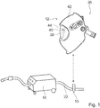
- FIG. 1 shows an active antiglare device 12, a detection device 10 and a welder 16.
- the welder 16 is formed by an electrically operated welder.
- the welder 16 is formed by an arc welder. In principle, however, another embodiment of a welder 16 that would appear meaningful to a person skilled in the art would also be conceivable.
- the anti-glare device 12 and the detection device 10 form a system 36.
- the anti-glare device 12 is intended to be worn on the head during operation by an operator.
- the anti-glare device 12 is formed by a welding helmet. In principle, however, another embodiment of the anti-glare device 12 that appears appropriate to a person skilled in the art would also be conceivable.
- the detection device 10 is formed separately from the anti-glare device 12.
- the anti-glare device 12 has an optical anti-glare filter 38.
- the anti-glare filter 38 is provided to change a permeability depending on a working condition and a drive dependent thereon.
- the optical anti-glare filter 38 is formed by an electro-optical filter.
- the optical anti-glare filter 38 is formed by an automatic darkening filter, ADF for short.
- the optical anti-glare filter 38 consists of several layers.
- the optical anti-glare filter 38 is designed as a multi-layer composite.
- the liquid crystal layer of the antiglare filter 38 is darkened during operation by the arithmetic unit 40 when a welding process is detected.
- the anti-glare filter 38 has a rectangular basic shape.
- the anti-glare device 12 has a shield unit 42.
- the anti-glare filter 38 is firmly received in the shield unit 42.
- the anti-glare filter 38 is fixed in position in the shield unit 42.
- the anti-glare device 12 also has an attachment disc.
- the attachment disc is connected to the shield unit 42 via not visible locking elements.
- the attachment disc is transparent.
- the attachment disc is provided to protect the anti-glare filter 38.
- the attachment disc hides the anti-glare filter 38 from the outside.
- the anti-glare device 12 has a communication unit 44.
- the communication unit 44 is provided for communication with the detection device 10 separate from the anti-glare device 12.
- the communication unit 44 is integrated into the arithmetic unit 40.
- the communication unit 44 forms part of the arithmetic unit 40. In principle, however, a separate embodiment of the communication unit 44 would also be conceivable.
- the anti-glare device 12 can receive signals for darkening the anti-glare filter 38.
- the glare protection device 12 can receive welding parameters A of the welding device 16 detected by means of the detection device 10. The welding parameters A of the welding device 16 are transmitted from the detection device 10 to the anti-glare device 12.
- the arithmetic unit 40 of the anti-glare device 12 is provided for an evaluation of the welding parameters A of the welding device 16. Furthermore, the arithmetic unit 40 is provided to darken the anti-glare filter 38, depending on the welding parameters A of the welding device 16. Here it would be In particular, it is conceivable that the arithmetic unit 40 automatically darkens the anti-glare filter 38 in the event of the absence of a signal from the detection device 10, the anti-glare filter 38. In this way, in the absence of a signal from the detection device 10, for example, due to a large distance between the anti-glare device 12 and the detection device 10, damage to the operator could be excluded. In addition or alternatively, however, it would also be conceivable that the arithmetic unit 40 has an additional sensor for detecting an arc of the welding device 16, by means of which the anti-glare filter 38 can also be darkened.
- the detection device 10 is provided for the active antiglare device 12.
- the detection device 10 forms an additional component for the antiglare device 12.
- the detection device 10 and the antiglare device 12 are provided for common use.
- the detection device 10 has a detection unit 14.
- the detection unit 14 is provided for a direct or indirect detection of at least one welding parameter A of the welding device 16.
- the detection unit 14 is provided for indirect detection of a current of the welding device 16.
- the detection unit 14 is provided for detecting a current flowing to the welding apparatus 16.
- the detection unit 14 has a current sensor 20.
- the current sensor 20 is provided for detecting the welding parameter A of the welding device 16.
- the current sensor 20 is provided for detecting a welding parameter A of the welding device 16 formed by a current.
- the current sensor 20 is provided for detecting the welding parameter A of the welding device 16 to be variably attached to a power cable 22 of the welding device 16.
- the power cable 22 of the welder 16 is formed by a burner and / or ground cable.
- the current sensor 20 is provided for detecting the at least one welding parameter A of the welding device 16 to be electrically contactless, to be variably attached to the power cable 22 of the welding device 16.
- the current sensor 20 is variably fixed in operation to a power cable 22 of the welder 16.
- the entire sensing device 10 is variably fixed in operation to a power cable 22 of the welder 16.
- the detection device 10 surrounds the power cable 22 of the welding device 16.
- the detection device 10 is fastened around the power cable 22 of the welding device 16 for this purpose.
- the detection device 10 forms a clamp.
- the detection device 10 may be at any Position on the power cable 22 of the welder 16 and to any welder 16 are attached.
- the detection device 10 is functional independently of a welding device 16 and can in particular be attached to welding devices 16 of various manufacturers ( FIGS. 1 . 5 ).
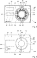
- the detection device 10 has a multi-part housing 34.
- the detection device 10 has a two-part housing 34.
- the housing 34 accommodates the detection unit 14 of the detection device 10.
- the housing 34 is intended to be mounted around the power cable 22 of the welder 16 without tools.
- the housing 34 has a first housing half 46 and a second housing half 48.
- the housing halves 46, 48 each have a recess 56, 58 for the power cable 22 on sides facing each other.
- the recesses 56, 58 of the housing halves 46, 48 are each formed semicircular.
- the recesses 56, 58 together form a circular recess.
- the housing halves 46, 48 can be connected to one another via a connection unit 50.
- the connection unit 50 comprises two first connection elements 52, 52 ', which are fixedly connected to the first housing half 46, and two second connection elements 54, 54', which are fixedly connected to the second housing half 48.
- the first and second connecting elements 52, 52 ', 54, 54' are screwed together to form a connection of the housing halves 46, 48.
- another connection technique that would appear meaningful to a person skilled in the art would also be conceivable, for example magnetically.
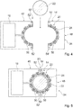
- the housing halves 46, 48 of the detection device 10 can therefore be separated and closed around the power cable 22 around again ( FIGS. 4, 5 ).
- the detection device 10 has a multi-part circuit board 35.
- the circuit board 35 is formed in two parts.
- the board 35 has two separate board elements 37, 37 '.
- the board elements 37, 37 ' are formed corresponding to the housing halves 46, 48.
- the first board element 37 is arranged in the first housing half 46.
- the second board element 37 ' is arranged in the second housing half 48.
- the board elements 37, 37 ' are intended to be mounted around the power cable 22 of the welder 16.
- the board elements 37, 37 ' have to the recesses 56, 58 of the housing halves 46, 48 corresponding recesses.
- the current sensor 20 of the detection unit 14 has a first sensor element 24.
- the first sensor element 24 is provided for detecting a current change in the power cable 22 of the welder 16.
- the first sensor element 24 engages in one operation the power cable 22 of the welding device 16.
- the first sensor element 24 of the current sensor 20 is arranged around the recesses 56, 58 of the housing halves 46, 48.
- the first sensor element 24 is formed in two parts. One half of the first sensor element 24 is arranged in the first housing half 46 and a second half of the first sensor element 24 is arranged in the second housing half 48.
- the halves of the first sensor element 24 are also connected in a connected state of the housing halves 46, 48.
- the connection of the two halves via a robust contact such as by means of a plug connection, a magnetic connection and / or a loose contact.
- the halves of the first sensor element 24 are electrically connected in a connected state of the housing halves 46, 48.
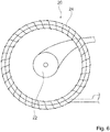
- the first sensor element 24 is formed by a Rogowski coil.
- the first sensor element 24 is formed by a Rogowski coil, which in an operation extends annularly around the power cable 22.
- the first sensor element 24 is formed by a Rogowski coil, which extends annularly around the recesses 56, 58.
- the Rogowski coil is composed of several sub-coils.
- the first sensor element 24 is partially applied to the first board element 37 and partially to the second board element 37 '.
- the first sensor element 24 consists of several air coils, with which the board elements 37, 37 'are equipped.
- the first sensor element 24 consists of several SMD-populated air coils ( Figures 2 . 4 . 6 ).
- the current sensor 20 of the detection unit 14 has a second sensor element 26.
- the second sensor element 26 is provided for detecting an absolute current value in the power cable 22 of the welder 16. With the second sensor element 26, a sustained current value can therefore be measured in particular.
- the second sensor element 26 has two measuring elements 60, 60 'which are arranged on opposite sides of the recesses 56, 58 of the housing halves 46, 48.
- the measuring elements 60, 60' are arranged in operation on opposite sides of the power cable 22.
- the measuring elements 60, 60 'of the second sensor element 26 are arranged in the first housing half 46 of the housing 34. In principle, however, would also be another, a professional useful Apparent arrangement of the second sensor element 26 conceivable.
- the second sensor element 26 is formed by a Hall sensor.
- the measuring elements 60, 60 'of the second sensor element 26 are each formed by Hall sensor boards. In principle, however, another embodiment of a second sensor element 26 which would appear meaningful to a person skilled in the art would also be conceivable
- the detection device 10 also has a communication unit 18.
- the communication unit 18 is provided for transmitting the welding parameter A to the active anti-glare device 12.
- the communication unit 18 of the detection device 10 is provided for communication with the communication unit 44 of the anti-glare device 12.
- the communication unit 18 of the detection device 10 is provided for a transmission of the welding parameter A to the communication unit 44 of the anti-glare device 12.
- the communication unit 18 is provided for a wireless transmission of the welding parameter A to the active anti-glare device 12.
- the communication unit 18 has a differential amplifier 28, an active rectifier 30 and / or a comparator 32 for fast data transmission.
- the communication unit 18 has a differential amplifier 28, an active rectifier 30 and a comparator 32 for fast data transmission.
- the communication unit 18 has a signal processing unit 62.
- the signal processing unit 62 is formed by an analog signal processing.
- the signal processing unit 62 is provided for disseminating the data of the detection unit 14.
- the signal processing unit 62 is provided for propagating the data of the detection unit 14 before sending.
- the signal processing unit 62 is directly coupled to the detection unit 14.
- the signal processing unit 62 comprises the differential amplifier 28, the active rectifier 30 and the comparator 32.
- the communication unit 18 has a transmitting unit 64.
- the transmitting unit 64 is provided for data transmission of the data of the signal processing unit 62.
- the transmission unit 64 is provided for a direct transmission of the data to the communication unit 44 of the antiglare device 12.
- the transmitting unit 64 is formed by a radio module.
- the transmitting unit 64 is formed by an RF module.
- the transmitting unit 64 is formed by a system-on-a-chip RF module, in short RF-SoC module. Furthermore, the communication unit 18 has a power supply unit 66. The power supply 66 serves for a power supply. The power supply 66 is over a Battery terminal 68 connected to a not further visible energy storage ( FIGS. 2, 3 ).
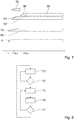
- FIG. 8 1 shows a schematic flow diagram of a method for operating the detection device 10 according to the invention.
- a current change in the power cable 22 of the welding device 16 is measured in a first method step 70 by means of the detection unit 14.
- a current change is constantly detected with the first sensor element 24, including the signal processing unit 62.
- the first method step 70 forms an idle state.
- a status signal "welding inactive" is continuously transmitted to the anti-glare device 12 via the communication unit 18. Due to the constant transmission of a status, a connection between the detection device 10 and the anti-glare device 12 can be monitored.
- a current change in the power cable 22 exceeds a predetermined limit. If a change in the current remains below the limit value, the first method step 70 is repeated. If the detected current change exceeds the limit value, this is immediately transmitted in a second method step 74 to the communication unit 18, which immediately transmits a status signal "active welding" to the anti-glare device 12. A transmission of the new status signal takes place in less than 50 microseconds. Subsequently, the anti-glare device 12 is darkened immediately in a third method step 76. Subsequently, the absolute current value in the power cable 22 is detected in a second branch 77. The absolute current value is detected by means of the second sensor element 26.
- the second method step 74 is repeated and the "welding active" status signal is continuously sent to the anti-glare device 12.
- the anti-glare device 12 therefore remains darkened. If the limit is not exceeded, the first method step 70 is repeated.
- the detection unit therefore returns to the idle state and sends the status signal "welding inactive".
- the shutter protection device 12 is opened again. After the transmission, the shutter protection device 12 therefore opens again.
- the opening of the anti-glare device 12 is in particular not so time-critical and can be done after a few milliseconds. This is the less favorable time behavior of the second sensor element 26 for the Acquisition of the welding end sufficient. Since the radio transmission always takes place continuously, in addition to the timely transmission of a new state, it is also possible to monitor the radio connection.
- FIG. 7 shows a schematic diagram of the response time of the detection device 10 compared to a conventional detection method in which the arc of the welding device 16 is optically detected.
- the welding parameter A formed by the current of the welding device 16 is shown as a bar.
- a structure of the arc as well as a subsequent beam 80 of the arc itself is applied.
- a closing operation of the anti-glare filter 38 and, subsequently, as a further bar 84, a closing state of the anti-glare filter 38 is applied to the detection device 10.
- a closing operation of the anti-glare filter 38 and, subsequently, as a further bar 88, a closing state of the anti-glare filter 38 is applied in a conventional detection method. Since the current is usually already detectable earlier and since the welding arc takes a certain amount of time to build up in most methods, a triggering of the welding protection can already take place during the arch construction, so that an accelerated darkening can be achieved.
- a bar 90 exemplifies the improved closing speed.
Landscapes
- Health & Medical Sciences (AREA)
- General Physics & Mathematics (AREA)
- Engineering & Computer Science (AREA)
- Physics & Mathematics (AREA)
- Life Sciences & Earth Sciences (AREA)
- Vascular Medicine (AREA)
- Heart & Thoracic Surgery (AREA)
- Animal Behavior & Ethology (AREA)
- General Health & Medical Sciences (AREA)
- Public Health (AREA)
- Veterinary Medicine (AREA)
- Biomedical Technology (AREA)
- Ophthalmology & Optometry (AREA)
- Power Engineering (AREA)
- Measuring Instrument Details And Bridges, And Automatic Balancing Devices (AREA)
Abstract
Die Erfindung geht aus von einer Erfassungsvorrichtung für eine aktive Blendschutzvorrichtung (12), mit einer Erfassungseinheit (14), welche zu einer direkten oder indirekten Erfassung zumindest eines Schweißparameters (A) eines Schweißgeräts (16) vorgesehen ist, und mit zumindest einer Kommunikationseinheit (18), welche zu einer Übertragung des zumindest einen Schweißparameters (A) an die aktive Blendschutzvorrichtung (12) vorgesehen ist.The invention relates to a detection device for an active antiglare device (12), comprising a detection unit (14), which is provided for directly or indirectly detecting at least one welding parameter (A) of a welding device (16), and having at least one communication unit (18 ), which is provided for a transmission of the at least one welding parameter (A) to the active anti-glare device (12).
Es wird vorgeschlagen, dass die Erfassungseinheit (14) zumindest einen Stromsensor (20) aufweist, welcher zu einer Erfassung des zumindest einen Schweißparameters (A) des Schweißgeräts (16) dazu vorgesehen ist, variabel an ein Stromkabel (22) des Schweißgeräts (16) befestigt zu werden.

Description
Die Erfindung betrifft eine Erfassungsvorrichtung für eine aktive Blendschutzvorrichtung.The invention relates to a detection device for an active anti-glare device.
Es ist bereits eine Erfassungsvorrichtung für eine aktive Blendschutzvorrichtung, mit einer Erfassungseinheit, welche zu einer direkten oder indirekten Erfassung zumindest eines Schweißparameters eines Schweißgeräts vorgesehen ist, und mit zumindest einer Kommunikationseinheit, welche zu einer Übertragung des zumindest einen Schweißparameters an die aktive Blendschutzvorrichtung vorgesehen ist, vorgeschlagen worden.It is already a detection device for an active anti-glare device, with a detection unit, which is provided for a direct or indirect detection of at least one welding parameter of a welding device, and with at least one communication unit, which is provided for a transmission of the at least one welding parameter to the active anti-glare device, been proposed.
Die Aufgabe der Erfindung besteht insbesondere darin, eine gattungsgemäße Vorrichtung mit verbesserten Eigenschaften hinsichtlich einer Reaktionszeit und Zuverlässigkeit bereitzustellen. Die Aufgabe wird erfindungsgemäß durch die Merkmale des Patentanspruchs 1 gelöst, während vorteilhafte Ausgestaltungen und Weiterbildungen der Erfindung den Unteransprüchen entnommen werden können.The object of the invention is in particular to provide a generic device with improved properties in terms of reaction time and reliability. The object is achieved by the features of claim 1, while advantageous embodiments and modifications of the invention can be taken from the dependent claims.
Die Erfindung geht aus von einer Erfassungsvorrichtung für eine aktive Blendschutzvorrichtung, mit einer Erfassungseinheit, welche zu einer direkten oder indirekten Erfassung zumindest eines Schweißparameters eines Schweißgeräts vorgesehen ist, und mit zumindest einer Kommunikationseinheit, welche zu einer Übertragung des zumindest einen Schweißparameters an die aktive Blendschutzvorrichtung vorgesehen ist.The invention is based on a detection device for an active antiglare device, with a detection unit, which is provided for a direct or indirect detection of at least one welding parameter of a welding device, and with at least one communication unit which provides for a transmission of the at least one welding parameter to the active antiglare device is.
Es wird vorgeschlagen, dass die Erfassungseinheit zumindest einen Stromsensor aufweist, welcher zu einer Erfassung des zumindest einen Schweißparameters des Schweißgeräts dazu vorgesehen ist, variabel an einem Stromkabel des Schweißgeräts befestigt zu werden. Unter einer "aktiven Blendschutzvorrichtung" soll in diesem Zusammenhang insbesondere eine Blendschutzvorrichtung mit einem aktiven optischen Blendschutzfilter verstanden werden. Dabei soll unter einer "Blendschutzvorrichtung" in diesem Zusammenhang insbesondere eine Vorrichtung verstanden werden, welche zu einem Schutz eines Benutzers vor zu großer Helligkeit und/oder vor Funken vorgesehen ist. Vorzugsweise soll darunter insbesondere eine Vorrichtung verstanden werden, welche zu einem Schutz von Augen und/oder einem Gesichtsbereich eines Benutzers während eines Schweiß- und/oder Schleifprozesses dient. Bevorzugt soll darunter insbesondere eine Blendschutzvorrichtung verstanden werden, welche insbesondere zu einem Schutz der Augen eines Benutzers zumindest während eines Schweißprozesses dient. Es sind verschiedene, einem Fachmann als sinnvoll erscheinende Ausgestaltungen einer Blendschutzvorrichtung denkbar, wie beispielsweise als Schweißhelm, -schirm, -maske und/oder -schild. Ferner soll dabei unter einem "aktiven optischen Blendschutzfilter" insbesondere ein optischer Filter verstanden werden, welcher insbesondere ein Schutzglas und/oder ein Kunststoffschutzglas bildet. Vorzugsweise soll darunter insbesondere ein optischer Filter verstanden werden, dessen Lichtdurchlässigkeit einstellbar ausgeführt ist. Bevorzugt soll darunter insbesondere ein optischer Schweißschutzfilter mit einer automatischen Verdunkelung verstanden werden. Besonders bevorzugt weist der Blendschutzfilter zumindest eine in der Transmission schaltbare Flüssigkristallebene auf. Es sind verschiedene, einem Fachmann als sinnvoll erscheinende Ausgestaltungen des optischen Blendschutzfilters denkbar, insbesondere soll darunter jedoch ein ADF, auch "automatic darkening filter" oder "automatischer Schweißerschutzfilter" genannt, verstanden werden. Des Weiteren soll unter einer "Erfassungseinheit" in diesem Zusammenhang insbesondere eine Einheit verstanden werden, welche zu einer direkten oder indirekten Erfassung zumindest eines Schweißparameters eines Schweißgeräts vorgesehen ist. Die Erfassungseinheit kann dabei insbesondere sowohl zu einer direkten Erfassung des Schweißparameters vorgesehen sein, als auch dazu vorgesehen sein, durch Erfassung alternativer Kenngrößen auf den zumindest einen Parameter zu schließen. Vorzugsweise umfasst die Erfassungseinheit zumindest einen Sensor. Dabei soll unter einem "Sensor" in diesem Zusammenhang insbesondere ein Element verstanden werden, das dazu vorgesehen ist, zumindest eine Kenngröße und/oder eine physikalische Eigenschaft aufzunehmen, wobei die Aufnahme aktiv, wie insbesondere durch Erzeugen und Aussenden eines elektrischen Messsignals, und/oder passiv, wie insbesondere durch eine Erfassung von Eigenschaftsänderungen eines Sensorbauteils, stattfinden kann. Es sind verschiedene, dem Fachmann als sinnvoll erscheinende Sensoren denkbar. Unter "vorgesehen" soll insbesondere speziell programmiert, ausgelegt und/oder ausgestattet verstanden werden. Darunter, dass ein Objekt zu einer bestimmten Funktion vorgesehen ist, soll insbesondere verstanden werden, dass das Objekt diese bestimmte Funktion in zumindest einem Anwendungs- und/oder Betriebszustand erfüllt und/oder ausführt.It is proposed that the detection unit has at least one current sensor, which is provided for detecting the at least one welding parameter of the welding device thereto, variably on a power cable of the welding device to be attached. In this context, an "active anti-glare device" is to be understood as meaning, in particular, an antiglare device with an active optical anti-glare filter. In this context, a "glare protection device" in this context should be understood to mean, in particular, a device which is provided to protect a user against excessive brightness and / or against sparks. Preferably, this is to be understood in particular as meaning a device which serves to protect the eyes and / or a face region of a user during a welding and / or grinding process. Preferably, this is to be understood as meaning, in particular, an antiglare device which, in particular, serves to protect the eyes of a user, at least during a welding process. Various forms of a glare protection device that appear appropriate to a person skilled in the art are conceivable, such as, for example, a welding helmet, shield, mask and / or shield. Furthermore, an "active optical anti-glare filter" is to be understood as meaning, in particular, an optical filter which in particular forms a protective glass and / or a plastic protective glass. Preferably, this is to be understood in particular as an optical filter whose light transmittance is designed to be adjustable. Preferably, this is to be understood in particular as an optical welding protection filter with an automatic darkening. Particularly preferably, the anti-glare filter has at least one switchable in the transmission liquid crystal plane. Various embodiments of the optical anti-glare filter which appear expedient to a person skilled in the art are conceivable, in particular, however, an ADF, also referred to as "automatic darkening filter" or "automatic welding protection filter", should be understood. Furthermore, a "detection unit" in this context should be understood to mean, in particular, a unit which is provided for a direct or indirect detection of at least one welding parameter of a welding apparatus. The detection unit may in particular be provided both for a direct detection of the welding parameter, as well as be provided to close by detecting alternative characteristics on the at least one parameter. Preferably, the detection unit comprises at least one sensor. In this context, a "sensor" in this context should be understood to mean, in particular, an element which is intended to accommodate at least one parameter and / or one physical characteristic, the recording being active, in particular by generating and emitting an electrical measurement signal, and / or passive, in particular by capturing Property changes of a sensor component, can take place. There are various conceivable to those skilled appear sensible sensors. By "provided" is intended to be understood in particular specially programmed, designed and / or equipped. The fact that an object is intended for a specific function should in particular mean that the object fulfills and / or executes this specific function in at least one application and / or operating state.
Unter einer "Kommunikationseinheit" soll in diesem Zusammenhang insbesondere eine Einheit verstanden werden, welche zu einer Bereitstellung einer, insbesondere kabellosen, Kommunikation mit der aktiven Blendschutzvorrichtung vorgesehen ist. Vorzugsweise weist die Kommunikationseinheit zu einer Kommunikation mit der aktiven Blendschutzvorrichtung zumindest eine Schnittstelle auf. Vorzugsweise soll unter einer Kommunikationseinheit insbesondere eine Einheit verstanden werden, welche zu einem Austausch von Daten vorgesehen ist. Insbesondere weist die Kommunikationseinheit zumindest einen Informationseingang und zumindest einen Informationsausgang auf. Vorzugsweise weist die Kommunikationseinheit zumindest zwei Informationseingänge und zumindest zwei Informationsausgänge auf, wobei jeweils zumindest ein Informationseingang und zumindest ein Informationsausgang zu einer Verbindung mit einem physischen System, insbesondere dem externen Schweißgerät, vorgesehen sind. Besonders bevorzugt soll darunter eine Schnittstelle zwischen zumindest zwei physischen Systemen, wie insbesondere zwischen der aktiven Blendschutzvorrichtung und der Erfassungsvorrichtung, verstanden werden. Es sind verschiedene, dem Fachmann als sinnvoll erscheinende Kommunikationseinheiten denkbar, insbesondere soll darunter jedoch eine drahtlose Schnittstelle, wie beispielsweise Bluetooth, WLAN, Zigbee, NFC, RFID, GSM, LTE oder UMTS, und/oder eine drahtgebundene Schnittstelle, wie beispielsweise ein USB-Anschluss, eine Canbus-Schnittstelle, eine RS485 Schnittstelle, eine Ethernet-Schnittstelle, eine optische Schnittstelle, eine KNX-Schnittstelle und/oder eine Powerline-Schnittstelle, verstanden werden.A "communication unit" is to be understood in this context, in particular, as a unit which is provided for providing a, in particular wireless, communication with the active anti-glare device. The communication unit preferably has at least one interface for communication with the active antiglare device. Preferably, a communication unit is to be understood as meaning in particular a unit which is provided for exchanging data. In particular, the communication unit has at least one information input and at least one information output. Preferably, the communication unit has at least two information inputs and at least two information outputs, wherein in each case at least one information input and at least one information output are provided for connection to a physical system, in particular the external welding device. Particularly preferred is to be understood as an interface between at least two physical systems, such as in particular between the active anti-glare device and the detection device. Various communication units that appear reasonable to a person skilled in the art are conceivable, in particular, however, a wireless interface, such as Bluetooth, WLAN, Zigbee, NFC, RFID, GSM, LTE or UMTS, for example, and / or a wired interface, such as a USB interface. Connection, a Canbus interface, an RS485 interface, an Ethernet interface, an optical interface, a KNX interface and / or a powerline interface are understood.
Ferner soll in diesem Zusammenhang unter einem "Stromsensor" insbesondere ein Sensor verstanden werden, welcher dazu vorgesehen ist, direkt, wie insbesondere mittels elektrischer Kontakte, oder indirekt, wie beispielsweise durch eine Kabelisolierung hindurch, wie insbesondere mittels einer Spule und/oder einem Hall-Sensor, auf eine Stromstärke und/oder eine Stromänderung zu schließen. Es sind verschiedene, einem Fachmann als sinnvoll erscheinende Stromsensoren denkbar. Darunter, dass der "Stromsensor dazu vorgesehen ist, variabel an ein Stromkabel des Schweißgeräts befestigt zu werden", soll in diesem Zusammenhang insbesondere verstanden werden, dass der Stromsensor dazu vorgesehen ist, unabhängig von einem Schweißgerät an ein Stromkabel eines Schweißgeräts befestigt zu werden. Vorzugsweise kann der Stromsensor an einer beliebigen Position an dem Stromkabel des Schweißgeräts befestigt werden. Bevorzugt soll darunter insbesondere verstanden werden, dass der Stromsensor dazu vorgesehen ist, optional und unabhängig von dem Schweißgerät an das Stromkabel des Schweißgeräts befestigt zu werden. Vorzugsweise soll darunter insbesondere verstanden werden, dass der Stromsensor kein Teil des Schweigeräts ist. Vorzugsweise kann der Stromsensor beispielsweise zwischen einem Stecker des Schweißgeräts und einer Steckdose angeordnet werden. Bei einer entsprechenden Ausgestaltung wäre insbesondere denkbar, dass die Erfassungsvorrichtung bei einer fehlenden oder fehlerhaften Kommunikation mit der aktiven Blendschutzvorrichtung eine Energiezufuhr des Schweißgeräts unterbricht. Hierdurch kann insbesondere sinnvoll ein Bediener geschützt werden.Furthermore, in this context, a "current sensor" should be understood to mean, in particular, a sensor which is intended to be directly, in particular by means of electrical contacts, or indirectly, for example by a cable insulation, in particular by means of a coil and / or a reverb. Sensor to close on a current strength and / or a current change. They are different, one Professional thought reasonable sense current sensors conceivable. In this context, it should be understood, in particular, that the current sensor is intended to be attached to a power cable of a welding device independently of a welding device. Preferably, the current sensor may be attached to any position on the power cable of the welder. Preferably, this is to be understood in particular as meaning that the current sensor is intended to be attached to the power cable of the welding device, optionally and independently of the welding device. Preferably, it should be understood in particular that the current sensor is not part of the Schweigeräts. Preferably, the current sensor can be arranged, for example, between a plug of the welding device and a socket. In a corresponding embodiment, it would be conceivable, in particular, for the detection device to interrupt an energy supply of the welding device in the event of missing or erroneous communication with the active anti-glare device. In this way, an operator can be protected in a particularly meaningful way.
Durch die erfindungsgemäß Ausgestaltung der Erfassungsvorrichtung kann insbesondere eine schnelle und zuverlässige Erfassung des zumindest einen Schweißparameters des Schweißgeräts erreicht werden. Vorzugsweise kann dadurch insbesondere zu einer Frühabdunkelung des aktiven Blendschutzfilters zuverlässig und insbesondere unabhängig von dem Schweißgerät ein Strom des Schweißgeräts erfasst werden. Insbesondere kann der Strom des Schweißgeräts, welcher zu einer Erzeugung eines Schweisslichtbogens benötigt wird, meist schon früher detektiert werden, als ein Schweisslichtbogen optisch erfasst werden kann, da der Schweisslichtbogen bei den meisten Verfahren eine gewisse Zeit benötigt, um sich aufzubauen. Erfolgt also in dieser Zeit eine Triggerung des aktiven Blendschutzfilters, kann bereits während eines Aufbaus des Schweisslichtbogens genau auf die zur optischen Detektion benötigte Helligkeit des Schweisslichtbogens abgedunkelt werden. Hierdurch kann insbesondere, vorzugsweise gegenüber einer optischen Detektion, eine vorteilhaft schnelle Abdunkelung der aktiven Blendschutzvorrichtung erreicht werden. Die Erfassung eines entstehenden Schweisslichtbogens erfolgt insbesondere durch die Detektion einer starken Stromänderung.In particular, a fast and reliable detection of the at least one welding parameter of the welding device can be achieved by the configuration of the detection device according to the invention. Preferably, in particular for an early darkening of the active antiglare filter, a current of the welding device can be detected reliably and in particular independently of the welding device. In particular, the current of the welding device, which is required for generating a welding arc, can usually be detected earlier than a welding arc can be optically detected, since the welding arc takes a certain amount of time to build up in most methods. Thus, if a triggering of the active anti-glare filter takes place during this time, it is possible to darken precisely to the brightness of the welding arc required for optical detection during a build-up of the welding arc. As a result, in particular, preferably with respect to an optical detection, an advantageously rapid darkening of the active antiglare device can be achieved. The detection of a developing welding arc takes place in particular by the detection of a strong current change.
Ferner wird vorgeschlagen, dass der Stromsensor zu einer Erfassung des zumindest einen Schweißparameters des Schweißgeräts dazu vorgesehen ist, elektrisch kontaktlos, variabel an das Stromkabel des Schweißgeräts befestigt zu werden. Vorzugsweise ist der Stromsensor zu einer Erfassung des zumindest einen Schweißparameters des Schweißgeräts dazu vorgesehen, elektrisch kontaktlos, das Stromkabel des Schweißgeräts umgreifend, an das Stromkabel befestigt zu werden. Unter "elektrisch kontaktlos" soll in diesem Zusammenhang insbesondere verstanden werden, dass der Stromsensor einen stromführenden Teil des Stromkabels nicht berührt. Vorzugsweise weist der Stromsensor keinen elektrischen Kontakt zu einer Kontaktierung eines stromführenden Teils des Stromkabels auf. Dadurch kann insbesondere eine vorteilhaft variable Anordnung des Stromsensors an dem Stromkabel erreicht werden. Es kann insbesondere erreicht werden, dass der Stromsensor beliebig und komfortabel positioniert werden kann.Furthermore, it is proposed that the current sensor for detecting the at least one welding parameter of the welding device is provided for being electrically contactlessly and variably attached to the power cable of the welding device. Preferably, the current sensor for detecting the at least one welding parameter of the welding device is provided to be electrically contactless, encompassing the power cable of the welding device, to be attached to the power cable. In this context, the term "electrically contactless" should be understood in particular to mean that the current sensor does not touch a current-carrying part of the power cable. Preferably, the current sensor has no electrical contact with a contacting of a current-carrying part of the power cable. As a result, in particular an advantageously variable arrangement of the current sensor can be achieved on the power cable. In particular, it can be achieved that the current sensor can be positioned arbitrarily and conveniently.
Des Weiteren wird vorgeschlagen, dass der zumindest eine Stromsensor der Erfassungseinheit zumindest ein erstes Sensorelement aufweist, welches zu einer Erfassung einer Stromänderung in dem Stromkabel des Schweißgeräts vorgesehen ist. Vorzugsweise erfasst das erste Sensorelement eine reine Stromänderung in dem Stromkabel. Dadurch kann insbesondere vorteilhaft zuverlässig eine Aktivierung des Schweißgeräts erfasst werden. Es kann insbesondere vorteilhaft schnell und zuverlässig eine Aktivierung des Schweißgeräts erfasst werden.Furthermore, it is proposed that the at least one current sensor of the detection unit has at least one first sensor element which is provided for detecting a change in current in the power cable of the welding device. Preferably, the first sensor element detects a pure current change in the power cable. As a result, an activation of the welding device can be detected particularly advantageously reliably. It can be detected particularly advantageous quickly and reliably activation of the welding device.
Zudem wird vorgeschlagen, dass das zumindest eine erste Sensorelement von einer Rogowskispule gebildet ist. Unter einer "Rogowskispule" soll insbesondere eine toroidförmige Luftspule verstanden werden. Vorzugsweise soll darunter insbesondere eine Spule frei von einem ferromagnetischen Kern verstanden werden. Mittels der Rogowskispule sind extrem kurze Detektionsvorgänge möglich, wie insbesondere im Bereich von 1 µs. Die Spule erkennt insbesondere nur Stromänderungen und schlägt somit beim Einschalten des Stroms aus. Bei konstantem Strom gibt die Spule keinen Wert aus. Hierdurch kann eine vorteilhaft schnelle Detektion einer Stromänderung erreicht werden. Es kann insbesondere unabhängig von einer Größenordnung der Stromänderung zuverlässig die Stromänderung detektiert werden.In addition, it is proposed that the at least one first sensor element is formed by a Rogowski coil. Under a "Rogowski coil" is to be understood in particular a toroidal air coil. Preferably, this is to be understood in particular as meaning a coil free of a ferromagnetic core. By means of the Rogowski coil extremely short detection processes are possible, in particular in the range of 1 μs. In particular, the coil recognizes only current changes and thus fails when switching on the current. At constant current, the coil outputs no value. As a result, an advantageously rapid detection of a change in current can be achieved. In particular, the current change can be detected reliably regardless of an order of magnitude of the current change.
Es wird ferner vorgeschlagen, dass der zumindest eine Stromsensor der Erfassungseinheit zumindest ein zweites Sensorelement aufweist, welches zu einer Erfassung eines absoluten Stromwerts in dem Stromkabel des Schweißgeräts vorgesehen ist. Vorzugsweise ist das zweite Sensorelement zu einer Erfassung eines absoluten Stromwerts und damit insbesondere auch zu einer Erfassung anhaltender Stromwerte in dem Stromkabel des Schweißgeräts vorgesehen. Dadurch kann insbesondere vorteilhaft zuverlässig festgestellt werden, ob ein Schweißprozess aktiv ist. Vorzugsweise kann dadurch insbesondere ein Sensorelement bereitgestellt werden, mittels welchem ein Schweißende erfasst werden kann und mittels welchem festgelegt werden kann, ab welchem Stromgrenzwert der Blendenschutz wieder geöffnet werden soll.It is further proposed that the at least one current sensor of the detection unit has at least one second sensor element, which leads to a Detecting an absolute current value is provided in the power cable of the welding machine. The second sensor element is preferably provided for detecting an absolute current value and thus in particular also for detecting sustained current values in the power cable of the welding device. As a result, it can be determined, particularly advantageously, reliably whether a welding process is active. In particular, a sensor element can thereby be provided by means of which a welding end can be detected and by means of which it can be determined from which current limit value the shutter protection is to be opened again.
Es wird weiter vorgeschlagen, dass das zumindest eine zweite Sensorelement von einem Hallsensor gebildet ist. Vorzugsweise dient der Hallsensor dazu, einen anhaltenden absoluten Stromwert zu erkennen, um abhängig davon einen Shutter der aktiven Blendschutzvorrichtung abgedunkelt zu halten. Ein Hallsensor alleine wäre jedoch insbesondere zu langsam, um den Initialstrompuls zu erkennen. Zu einer Erkennung des Initialstrompulses wird daher insbesondere die Rogowskispule genutzt. Dadurch kann insbesondere eine vorteilhaft zuverlässige Erfassung eines absoluten Stromwerts, insbesonder elektrisch kontaktlos, erreicht werden. Der Hallsensor wird insbesondere zu einer Sicherstellung einer zuverlässigen Detektion eines anhaltenden Gleichstroms verwendet.It is further proposed that the at least one second sensor element is formed by a Hall sensor. The Hall sensor preferably serves to detect a sustained absolute current value in order to keep a shutter of the active antiglare device darkened as a function thereof. However, a Hall sensor alone would be particularly too slow to detect the initial current pulse. For detection of the initial current pulse, therefore, the Rogowski coil is used in particular. As a result, in particular an advantageously reliable detection of an absolute current value, in particular electrically contactless, can be achieved. The Hall sensor is used in particular to ensure a reliable detection of a sustained direct current.
Ferner wird vorgeschlagen, dass die zumindest eine Kommunikationseinheit zu einer kabellosen Übertragung des zumindest einen Schweißparameters an die aktive Blendschutzvorrichtung vorgesehen ist. Vorzugsweise soll eine Übertragung dabei in weniger als 20 µs erfolgen. Hierdurch kann insbesondere auf ein Verbindungskabel zwischen der aktiven Blendschutzvorrichtung und dem Schweißgerät bzw. der Erfassungsvorrichtung verzichtet werden. Es kann insbesondere eine vorteilhaft komfortable Nutzung gewährleistet werden.It is also proposed that the at least one communication unit is provided for a wireless transmission of the at least one welding parameter to the active anti-glare device. Preferably, a transmission should take place in less than 20 μs. This makes it possible in particular to dispense with a connecting cable between the active antiglare device and the welding device or the detection device. In particular, advantageously advantageous use can be ensured.
Des Weiteren wird vorgeschlagen, dass die zumindest eine Kommunikationseinheit zu einer schnellen Datenübertragung zumindest einen Differentialverstärker, zumindest einen aktiven Gleichrichter und/oder zumindest einen Komparator aufweist. Durch die Kopplung von verschiedenen Verarbeitungsstufen wird insbesondere ein eindeutiges Signal erzeugt. Dies gibt entweder ein "Schweißen aktiv" oder "inaktiv" auf einem Signalausgang, insbesondere einem TTL-Signalausgang, aus. Das Signal wird vorzugsweise anschließend mittels schneller Datenübertragung kabellos an den aktiven Blendschutzfilter gesendet. Die Signalaufbereitung wird insbesondere durch einen Differentialverstärker, einen aktiven Gleichrichter und abschliessend durch einen Komparator sichergestellt. Unter einem "Differentialverstärker" soll in diesem Zusammenhang insbesondere ein elektronisches Bauteil verstanden werden, welches zu einer Verstärkung zumindest eines Eingangssignals vorgesehen ist. Vorzugsweise soll darunter insbesondere ein Verstärker mit zumindest zwei Eingängen verstanden werden. Der aktive Gleichrichter dient insbesondere der Gleichrichtung eines verstärkten Ausgangssignals zumindest eines Sensorelements des Stromsensors, insbesondere der Rogowskispule, welches bezogen zu einer Referenzspannung in Abhängigkeit von der Stromrichtung positiv oder negativ ausfallen kann. Durch die aktive Gleichrichtung kann insbesondere erreicht werden, dass der Schweißstrom richtungsunabhängig erfasst werden kann. Der Komfort wird erhöht, da der Sensor keine Vorzugsrichtung bei der Montage um das Schweisskabel aufweisen muss. Die gesamte analoge Signalaufbereitung, insbesondere in Verbindung mit der Rogowskispule, kann eine sehr schnelle und zuverlässige Erfassung des Schweißbeginns sicherstellen.Furthermore, it is proposed that the at least one communication unit has at least one differential amplifier, at least one active rectifier and / or at least one comparator for rapid data transmission. In particular, a unique signal is generated by the coupling of different processing stages. This outputs either a "welding active" or "inactive" on a signal output, especially a TTL signal output. The signal is preferably then sent by wireless data transmission wirelessly to the active anti-glare filter. The signal conditioning is ensured in particular by a differential amplifier, an active rectifier and finally by a comparator. A "differential amplifier" is to be understood in this context, in particular an electronic component, which is provided to amplify at least one input signal. Preferably, this is to be understood as meaning, in particular, an amplifier having at least two inputs. The active rectifier serves, in particular, to rectify an amplified output signal of at least one sensor element of the current sensor, in particular of the Rogowski coil, which can be positive or negative with respect to a reference voltage as a function of the current direction. By active rectification can be achieved in particular that the welding current can be detected independently of direction. The comfort is increased since the sensor does not have to have a preferred direction when mounting around the welding cable. The entire analog signal conditioning, especially in connection with the Rogowski coil, can ensure a very fast and reliable detection of the start of welding.
Es wird ferner vorgeschlagen, dass die Erfassungsvorrichtung zumindest ein zumindest teilweise mehrteiliges Gehäuse aufweist, welches dazu vorgesehen ist, insbesondere werkzeuglos um das Stromkabel des Schweißgeräts herum montiert zu werden. Vorzugsweise besteht das Gehäuse aus zwei Hälften oder auch einem Verbund und kann um das Kabel herummontiert werden. Bevorzugt bildet das Gehäuse eine Art Schelle, welche werkzeuglos entfernt und montiert werden kann. Es wäre auch denkbar, eine Schleife oder dergleichen um das Kabel zu binden. Es muss insbesondere sichergestellt sein, dass der Stromkreis des ersten Sensorelements geschlossen werden kann. Dadurch kann insbesondere eine einfache und schnelle Montage der Erfassungsvorrichtung erreicht werden. Hierdurch kann insbesondere eine komfortable Bedienung der Erfassungsvorrichtung ermöglicht werden.It is further proposed that the detection device has at least one at least partially multi-part housing, which is intended to be mounted in particular without tools around the power cable of the welding device around. Preferably, the housing consists of two halves or a composite and can be mounted around the cable. Preferably, the housing forms a kind of clamp, which can be removed and mounted without tools. It would also be conceivable to tie a loop or the like around the cable. In particular, it must be ensured that the circuit of the first sensor element can be closed. As a result, in particular a simple and quick installation of the detection device can be achieved. In this way, in particular a comfortable operation of the detection device can be made possible.
Es wird weiter vorgeschlagen, dass die Erfassungsvorrichtung zumindest eine mehrteilige Platine aufweist, die zumindest zwei, zumindest teilweise getrennte Platinenelemente aufweist, welche dazu vorgesehen sind, um das Stromkabel des Schweißgeräts herum montiert zu werden, wobei das zumindest eine erste Sensorelement zumindest teilweise auf das erste Platinenelement und zumindest teilweise auf das zweite Platinenelement aufgebracht ist. Vorzugsweise ist die Platine als geteilte Platine ausgebildet, welche mit SMD bestückbaren Induktivitäten, insbesondere einzelnen Luftspulen der Rogowskispule, bestückt ist. Dadurch kann insbesondere eine einfache und schnelle Montage der Erfassungsvorrichtung erreicht werden. Ferner kann eine vorteilhafte Funktionalität des Stromsensors erreicht werden.It is further proposed that the detection device comprises at least one multi-part circuit board having at least two, at least partially separate board elements, which are intended to be mounted around the power cable of the welding device, wherein the at least one first sensor element at least partially on the first Board element and at least partially on the second board element is applied. Preferably, the board is formed as a split board, which is equipped with SMD inductors, in particular individual air coils of Rogowski coil equipped. As a result, in particular a simple and quick installation of the detection device can be achieved. Furthermore, an advantageous functionality of the current sensor can be achieved.
Ferner wird ein System mit einer aktiven Blendschutzvorrichtung und mit der Erfassungsvorrichtung vorgeschlagen.Furthermore, a system with an active antiglare device and with the detection device is proposed.
Des Weiteren wird ein Verfahren zu einem Betrieb der Erfassungsvorrichtung vorgeschlagen.Furthermore, a method for operating the detection device is proposed.
Die erfindungsgemäße Erfassungsvorrichtung, das System sowie das Verfahren sollen hierbei nicht auf die oben beschriebene Anwendung und Ausführungsform beschränkt sein. Insbesondere können die erfindungsgemäße Erfassungsvorrichtung, das System sowie das Verfahren zu einer Erfüllung einer hierin beschriebenen Funktionsweise eine von einer hierin genannten Anzahl von einzelnen Elementen, Bauteilen und Einheiten abweichende Anzahl aufweisen.The detection device according to the invention, the system and the method should not be limited to the application and embodiment described above. In particular, the detection device according to the invention, the system and the method for performing a function described herein may have a different number than a number of individual elements, components and units mentioned herein.
Weitere Vorteile ergeben sich aus der folgenden Zeichnungsbeschreibung. In den Zeichnungen ist ein Ausführungsbeispiel der Erfindung dargestellt. Die Zeichnungen, die Beschreibung und die Ansprüche enthalten zahlreiche Merkmale in Kombination. Der Fachmann wird die Merkmale zweckmäßigerweise auch einzeln betrachten und zu sinnvollen weiteren Kombinationen zusammenfassen.Further advantages emerge from the following description of the drawing. In the drawings, an embodiment of the invention is shown. The drawings, the description and the claims contain numerous features in combination. The person skilled in the art will expediently also consider the features individually and combine them into meaningful further combinations.
Es zeigen:
- Fig. 1
- ein System mit einer aktiven Blendschutzvorrichtung und mit einer erfindungsgemäßen Erfassungsvorrichtung und ein Schweißgerät in einer schematischen Darstellung,
- Fig. 2
- die erfindungsgemäße Erfassungsvorrichtung mit einer Erfassungseinheit und mit einer Kommunikationseinheit in einer schematischen Vorderansicht,
- Fig. 3
- die erfindungsgemäße Erfassungsvorrichtung mit der Erfassungseinheit und mit der Kommunikationseinheit in einer schematischen Rückansicht,
- Fig. 4
- die erfindungsgemäße Erfassungsvorrichtung während einer Montage an einem Stromkabel des Schweißgeräts in einer stark schematischen Darstellung,
- Fig. 5
- die erfindungsgemäße Erfassungsvorrichtung nach einer Montage an dem Stromkabel des Schweißgeräts in einer stark schematischen Darstellung,
- Fig. 6
- ein erstes Sensorelement eines Stromsensors der Erfassungseinheit der erfindungsgemäßen Erfassungsvorrichtung in einer schematischen Darstellung,
- Fig. 7
- ein schematisches Diagramm einer Reaktionszeit der erfindungsgemäßen Erfassungsvorrichtung gegenüber einer herkömmlichen optischen Erfassung und
- Fig. 8
- ein schematisches Ablaufdiagramm eines Verfahrens zu einem Betrieb der erfindungsgemäßen Erfassungsvorrichtung.
- Fig. 1
- a system with an active antiglare device and with a detection device according to the invention and a welding device in a schematic representation,
- Fig. 2
- the detection device according to the invention with a detection unit and with a communication unit in a schematic front view,
- Fig. 3
- the detection device according to the invention with the detection unit and with the communication unit in a schematic rear view,
- Fig. 4
- the detection device according to the invention during a mounting on a power cable of the welding device in a highly schematic representation,
- Fig. 5
- the detection device according to the invention after mounting on the power cable of the welding device in a highly schematic representation,
- Fig. 6
- a first sensor element of a current sensor of the detection unit of the detection device according to the invention in a schematic representation,
- Fig. 7
- a schematic diagram of a reaction time of the detection device according to the invention over a conventional optical detection and
- Fig. 8
- a schematic flow diagram of a method for operating the detection device according to the invention.
Die Blendschutzvorrichtung 12 und die Erfassungsvorrichtung 10 bilden ein System 36 aus. Die Blendschutzvorrichtung 12 ist dazu vorgesehen, während eines Betriebs von einem Bediener auf dem Kopf getragen zu werden. Die Blendschutzvorrichtung 12 ist von einem Schweißhelm gebildet. Grundsätzlich wäre jedoch auch eine andere, einem Fachmann als sinnvoll erscheinende Ausbildung der Blendschutzvorrichtung 12 denkbar. Die Erfassungsvorrichtung 10 ist von der Blendschutzvorrichtung 12 getrennt ausgebildet.The
Die Blendschutzvorrichtung 12 weist einen optischen Blendschutzfilter 38 auf. Der Blendschutzfilter 38 ist dazu vorgesehen, abhängig von einem Arbeitszustand und einer davon abhängigen Ansteuerung eine Durchlässigkeit zu verändern. Der optische Blendschutzfilter 38 ist von einem elektrooptischen Filter gebildet. Der optische Blendschutzfilter 38 ist von einem automatic darkening filter, kurz ADF, gebildet. Der optische Blendschutzfilter 38 besteht aus mehreren Schichten. Der optische Blendschutzfilter 38 ist als ein Mehrschichtverbund ausgebildet. Die Flüssigkristallschicht des Blendschutzfilters 38 wird während eines Betriebs von der Recheneinheit 40 abgedunkelt, wenn ein Schweißverfahren erfasst wird. Der Blendschutzfilter 38 weist eine rechteckige Grundform auf.The
Ferner weist die Blendschutzvorrichtung 12 eine Schildeinheit 42 auf. Der Blendschutzfilter 38 ist fest in der Schildeinheit 42 aufgenommen. Der Blendschutzfilter 38 ist positionsfest in der Schildeinheit 42 aufgenommen. Die Blendschutzvorrichtung 12 weist ferner eine Vorsatzscheibe auf. Die Vorsatzscheibe ist mit der Schildeinheit 42 über nicht weiter sichtbare Rastelemente verbunden. Die Vorsatzscheibe ist transparent ausgebildet. Die Vorsatzscheibe ist zu einem Schutz des Blendschutzfilters 38 vorgesehen. Die Vorsatzscheibe verdeckt den Blendschutzfilter 38 von außen.Furthermore, the
Des Weiteren weist die Blendschutzvorrichtung 12 eine Kommunikationseinheit 44 auf. Die Kommunikationseinheit 44 ist zu einer Kommunikation mit der von der Blendschutzvorrichtung 12 getrennten Erfassungsvorrichtung 10 vorgesehen. Die Kommunikationseinheit 44 ist in die Recheneinheit 40 integriert. Die Kommunikationseinheit 44 bildet ein Teil der Recheneinheit 40. Grundsätzlich wäre jedoch auch eine separate Ausbildung der Kommunikationseinheit 44 denkbar. Über die Kommunikationseinheit 44 kann die Blendschutzvorrichtung 12 Signale zu einer Abdunkelung des Blendschutzfilters 38 empfangen. Über die Kommunikationseinheit 44 kann die Blendschutzvorrichtung 12 mittels der Erfassungsvorrichtung 10 erfasste Schweißparameter A des Schweißgeräts 16 empfangen. Die Schweißparameter A des Schweißgeräts 16 werden von der Erfassungsvorrichtung 10 an die Blendschutzvorrichtung 12 übertragen. Die Recheneinheit 40 der Blendschutzvorrichtung 12 ist zu einer Auswertung der Schweißparameter A des Schweißgeräts 16 vorgesehen. Ferner ist die Recheneinheit 40 dazu vorgesehen, abhängig von den Schweißparametern A des Schweißgeräts 16 den Blendschutzfilter 38 abzudunkeln. Hierbei wäre es insbesondere denkbar, dass die Recheneinheit 40 den Blendschutzfilter 38 bei einem Ausbleiben eines Signals von der Erfassungsvorrichtung 10 den Blendschutzfilter 38 automatisch abdunkelt. Hierdurch könnte bei einem Ausbleiben eines Signals von der Erfassungsvorrichtung 10, beispielsweise aufgrund einer zu großen Entfernung zwischen der Blendschutzvorrichtung 12 und der Erfassungsvorrichtung 10, eine Schädigung des Bedieners ausgeschlossen werden. Zudem oder alternativ wäre jedoch auch denkbar, dass die Recheneinheit 40 einen zusätzlichen Sensor zu einer Erfassung eines Lichtbogens des Schweißgeräts 16 aufweist, mittels welchem der Blendschutzfilter 38 ebenfalls abgedunkelt werden kann.Furthermore, the
Die Erfassungsvorrichtung 10 ist für die aktive Blendschutzvorrichtung 12 vorgesehen. Die Erfassungsvorrichtung 10 bildet ein Zusatzbauteil für die Blendschutzvorrichtung 12. Die Erfassungsvorrichtung 10 und die Blendschutzvorrichtung 12 sind zu einer gemeinsamen Benutzung vorgesehen. Die Erfassungsvorrichtung 10 weist eine Erfassungseinheit 14 auf. Die Erfassungseinheit 14 ist zu einer direkten oder indirekten Erfassung zumindest eines Schweißparameters A des Schweißgeräts 16 vorgesehen. Die Erfassungseinheit 14 ist zu einer indirekten Erfassung eines Stroms des Schweißgeräts 16 vorgesehen. Die Erfassungseinheit 14 ist zu einer Erfassung eines zu dem Schweißgerät 16 fließenden Stroms vorgesehen. Die Erfassungseinheit 14 weist einen Stromsensor 20 auf. Der Stromsensor 20 ist zu einer Erfassung des Schweißparameters A des Schweißgeräts 16 vorgesehen. Der Stromsensor 20 ist zu einer Erfassung eines von einem Strom gebildeten Schweißparameters A des Schweißgeräts 16 vorgesehen. Der Stromsensor 20 ist zu einer Erfassung des Schweißparameters A des Schweißgeräts 16 dazu vorgesehen, variabel an ein Stromkabel 22 des Schweißgeräts 16 befestigt zu werden. Das Stromkabel 22 des Schweißgeräts 16 ist von einem Brenner- und/oder Massekabel gebildet. Der Stromsensor 20 ist zu einer Erfassung des zumindest einen Schweißparameters A des Schweißgeräts 16 dazu vorgesehen, elektrisch kontaktlos, variabel an das Stromkabel 22 des Schweißgeräts 16 befestigt zu werden. Der Stromsensor 20 ist in einem Betrieb variabel an ein Stromkabel 22 des Schweißgeräts 16 befestigt. Die gesamte Erfassungsvorrichtung 10 ist in einem Betrieb variabel an ein Stromkabel 22 des Schweißgeräts 16 befestigt. Die Erfassungsvorrichtung 10 umgreift dazu das Stromkabel 22 des Schweißgeräts 16. Die Erfassungsvorrichtung 10 wird dazu um das Stromkabel 22 des Schweißgeräts 16 herum befestigt. Die Erfassungsvorrichtung 10 bildet eine Schelle aus. Die Erfassungsvorrichtung 10 kann an einer beliebigen Position an dem Stromkabel 22 des Schweißgeräts 16 sowie an einem beliebigen Schweißgerät 16 befestigt werden. Die Erfassungsvorrichtung 10 ist unabhängig von einem Schweißgerät 16 funktionsfähig und kann insbesondere an Schweißgeräte 16 verschiedener Hersteller befestigt werden (
Die Erfassungsvorrichtung 10 weist ein mehrteiliges Gehäuse 34 auf. Die Erfassungsvorrichtung 10 weist ein zweiteiliges Gehäuse 34 auf. Das Gehäuse 34 nimmt die Erfassungseinheit 14 der Erfassungsvorrichtung 10 auf. Das Gehäuse 34 ist dazu vorgesehen, werkzeuglos um das Stromkabel 22 des Schweißgeräts 16 herum montiert zu werden. Das Gehäuse 34 weist eine erste Gehäusehälfte 46 und eine zweite Gehäusehälfte 48 auf. Die Gehäusehälften 46, 48 weisen jeweils auf einander zugewandten Seiten eine Aussparung 56, 58 für das Stromkabel 22 auf. Die Aussparungen 56, 58 der Gehäusehälften 46, 48 sind jeweils halbkreisförmig ausgebildet. Die Aussparungen 56, 58 bilden gemeinsam eine kreisförmige Aussparung. Die Gehäusehälften 46, 48 sind über eine Verbindungseinheit 50 miteinander verbindbar. Die Verbindungseinheit 50 umfasst zwei erste Verbindungselemente 52, 52', welche fest mit der ersten Gehäusehälfte 46 verbunden sind, und zwei zweite Verbindungselemente 54, 54', welche fest mit der zweiten Gehäusehälfte 48 verbunden sind. Die ersten und zweiten Verbindungselemente 52, 52', 54, 54' werden zu einer Verbindung der Gehäusehälften 46, 48 miteinander verschraubt. Grundsätzlich wäre jedoch auch eine andere, einem Fachmann als sinnvoll erscheinende Verbindungstechnik denkbar, wie beispielsweise magnetisch. Zu einer Montage können die Gehäusehälften 46, 48 der Erfassungsvorrichtung 10 daher getrennt und um das Stromkabel 22 herum wieder geschlossen werden (
Ferner weist die Erfassungsvorrichtung 10 eine mehrteilige Platine 35 auf. Die Platine 35 ist zweiteilig ausgebildet. Die Platine 35 weist zwei getrennte Platinenelemente 37, 37' auf. Die Platinenelemente 37, 37' sind korrespondierend zu den Gehäusehälften 46, 48 ausgebildet. Das erste Platinenelement 37 ist in der ersten Gehäusehälfte 46 angeordnet. Das zweite Platinenelement 37' ist in der zweiten Gehäusehälfte 48 angeordnet. Die Platinenelemente 37, 37' sind dazu vorgesehen, um das Stromkabel 22 des Schweißgeräts 16 herum montiert zu werden. Die Platinenelemente 37, 37' weisen dazu zu den Aussparungen 56, 58 der Gehäusehälften 46, 48 korrespondierende Aussparungen auf.Furthermore, the
Ferner weist der Stromsensor 20 der Erfassungseinheit 14 ein erstes Sensorelement 24 auf. Das erste Sensorelement 24 ist zu einer Erfassung einer Stromänderung in dem Stromkabel 22 des Schweißgeräts 16 vorgesehen. Das erste Sensorelement 24 umgreift in einem Betrieb das Stromkabel 22 des Schweißgeräts 16. Das erste Sensorelement 24 des Stromsensor 20 ist um die Aussparungen 56, 58 der Gehäusehälften 46, 48 angeordnet. Das erste Sensorelement 24 ist zweiteilig ausgebildet. Eine Hälfte des ersten Sensorelements 24 ist in der ersten Gehäusehälfte 46 angeordnet und eine zweite Hälfte des ersten Sensorelements 24 ist in der zweiten Gehäusehälfte 48 angeordnet. Die Hälften des ersten Sensorelements 24 sind in einem verbundenen Zustand der Gehäusehälften 46, 48 ebenfalls verbunden. Die Verbindung der beiden Hälften erfolgt über eine robuste Kontaktierung, wie beispielsweise mittels einer Steckverbindung, einer Magnetverbindung und/oder einer losen Berührung. Die Hälften des ersten Sensorelements 24 sind in einem verbundenen Zustand der Gehäusehälften 46, 48 elektrisch verbunden. Das erste Sensorelement 24 ist von einer Rogowskispule gebildet. Das erste Sensorelement 24 ist von einer Rogowskispule gebildet, welche sich in einem Betrieb ringförmig um das Stromkabel 22 erstreckt. Das erste Sensorelement 24 ist von einer Rogowskispule gebildet, welche sich ringförmig um die Aussparungen 56, 58 erstreckt. Vorzugsweise ist die Rogowskispule aus mehreren Teilspulen zusammengesetzt. Das erste Sensorelement 24 ist teilweise auf das erste Platinenelement 37 und teilweise auf das zweite Platinenelement 37' aufgebracht. Das erste Sensorelement 24 besteht aus mehreren Luftspulen, mit welchen die Platinenelemente 37, 37' bestückt sind. Das erste Sensorelement 24 besteht aus mehreren SMD bestückbaren Luftspulen (
Des Weiteren weist der Stromsensor 20 der Erfassungseinheit 14 ein zweites Sensorelement 26 auf. Das zweite Sensorelement 26 ist zu einer Erfassung eines absoluten Stromwerts in dem Stromkabel 22 des Schweißgeräts 16 vorgesehen. Mit dem zweiten Sensorelement 26 ist daher insbesondere auch ein anhaltender Stromwert messbar. Das zweite Sensorelement 26 weist zwei Messelemente 60, 60' auf, welche auf gegenüberliegenden Seiten der Aussparungen 56, 58 der Gehäusehälften 46, 48 angeordnet sind, Die Messelemente 60, 60' sind in einem Betrieb auf gegenüberliegenden Seiten des Stromkabels 22 angeordnet. Die Messelemente 60, 60' des zweiten Sensorelements 26 sind in der ersten Gehäusehälfte 46 des Gehäuses 34 angeordnet. Grundsätzlich wäre jedoch auch eine andere, einem Fachmann als sinnvoll erscheinende Anordnung des zweiten Sensorelements 26 denkbar. Das zweite Sensorelement 26 ist von einem Hallsensor gebildet. Die Messelemente 60, 60' des zweiten Sensorelements 26 sind jeweils von Hallsensorboards gebildet. Grundsätzlich wäre jedoch auch eine andere, einem Fachmann als sinnvoll erscheinende Ausbildung des zweiten Sensorelements 26 denkbar (
Die Erfassungsvorrichtung 10 weist ferner eine Kommunikationseinheit 18 auf. Die Kommunikationseinheit 18 ist zu einer Übertragung des Schweißparameters A an die aktive Blendschutzvorrichtung 12 vorgesehen. Die Kommunikationseinheit 18 der Erfassungsvorrichtung 10 ist zu einer Kommunikation mit der Kommunikationseinheit 44 der Blendschutzvorrichtung 12 vorgesehen. Die Kommunikationseinheit 18 der Erfassungsvorrichtung 10 ist zu einer Übertragung des Schweißparameters A an die Kommunikationseinheit 44 der Blendschutzvorrichtung 12 vorgesehen. Die Kommunikationseinheit 18 ist zu einer kabellosen Übertragung des Schweißparameters A an die aktive Blendschutzvorrichtung 12 vorgesehen. Die Kommunikationseinheit 18 weist zu einer schnellen Datenübertragung einen Differentialverstärker 28, einen aktiven Gleichrichter 30 und/oder einen Komparator 32 auf. Die Kommunikationseinheit 18 weist zu einer schnellen Datenübertragung einen Differentialverstärker 28, einen aktiven Gleichrichter 30 und einen Komparator 32 auf. Die Kommunikationseinheit 18 weist eine Signalverarbeitungseinheit 62 auf. Die Signalverarbeitungseinheit 62 ist von einer analogen Signalverarbeitung gebildet. Die Signalverarbeitungseinheit 62 ist zu einer Verbreitung der Daten der Erfassungseinheit 14 vorgesehen. Die Signalverarbeitungseinheit 62 ist zu einer Verbreitung der Daten der Erfassungseinheit 14 vor einem Versenden vorgesehen. Die Signalverarbeitungseinheit 62 ist direkt mit der Erfassungseinheit 14 gekoppelt. Die Signalverarbeitungseinheit 62 umfasst den Differentialverstärker 28, den aktiven Gleichrichter 30 und den Komparator 32. Ferner weist die Kommunikationseinheit 18 eine Sendeeinheit 64 auf. Die Sendeeinheit 64 ist zu einer Datenübertragung der Daten der Signalverarbeitungseinheit 62 vorgesehen. Die Sendeeinheit 64 ist zu einer direkten Übertragung der Daten an die Kommunikationseinheit 44 der Blendschutzvorrichtung 12 vorgesehen. Die Sendeeinheit 64 ist von einem Funkmodul gebildet. Die Sendeeinheit 64 ist von einem RF-Modul gebildet. Die Sendeeinheit 64 ist von einem System-on-a-Chip-RF-Modul, kurz RF-SoC-Modul, gebildet. Des Weiteren weist die Kommunikationseinheit 18 ein Netzteil 66 auf. Das Netzteil 66 dient zu einer Energieversorgung. Das Netzteil 66 ist über einen Batterieanschluss 68 mit einem nicht weiter sichtbaren Energiespeicher verbunden (
Claims (12)
dadurch gekennzeichnet, dass
die Erfassungseinheit (14) zumindest einen Stromsensor (20) aufweist, welcher zu einer Erfassung des zumindest einen Schweißparameters (A) des Schweißgeräts (16) dazu vorgesehen ist, variabel an ein Stromkabel (22) des Schweißgeräts (16) befestigt zu werden.Detection device for an active antiglare device (12), comprising a detection unit (14), which is provided for direct or indirect detection of at least one welding parameter (A) of a welding device (16), and at least one communication unit (18), which for transmission the at least one welding parameter (A) is provided on the active antiglare device (12),
characterized in that
the detection unit (14) has at least one current sensor (20) which is provided for detecting the at least one welding parameter (A) of the welding device (16) to be variably attached to a power cable (22) of the welding device (16).
dadurch gekennzeichnet, dass
der Stromsensor (20) zu einer Erfassung des zumindest einen Schweißparameters (A) des Schweißgeräts (16) dazu vorgesehen ist, elektrisch kontaktlos, variabel an das Stromkabel (22) des Schweißgeräts (16) befestigt zu werden.Detection device according to claim 1,
characterized in that
the current sensor (20) is provided for detecting the at least one welding parameter (A) of the welding device (16) in order to be fixed electrically non-contact, variably to the power cable (22) of the welding device (16).
dadurch gekennzeichnet, dass
der zumindest eine Stromsensor (20) der Erfassungseinheit (14) zumindest ein erstes Sensorelement (24) aufweist, welches zu einer Erfassung einer Stromänderung in dem Stromkabel (22) des Schweißgeräts (16) vorgesehen ist.Detection device according to claim 1 or 2,
characterized in that
the at least one current sensor (20) of the detection unit (14) has at least one first sensor element (24) which is provided for detecting a change in current in the power cable (22) of the welding device (16).
dadurch gekennzeichnet, dass
das zumindest eine erste Sensorelement (24) von einer Rogowskispule gebildet ist.Detection device according to claim 3,
characterized in that
the at least one first sensor element (24) is formed by a Rogowski coil.
dadurch gekennzeichnet, dass
der zumindest eine Stromsensor (20) der Erfassungseinheit (14) zumindest ein zweites Sensorelement (26) aufweist, welches zu einer Erfassung eines absoluten Stromwerts in dem Stromkabel (22) des Schweißgeräts (16) vorgesehen ist.Detection device according to one of the preceding claims,
characterized in that
the at least one current sensor (20) of the detection unit (14) has at least one second sensor element (26) which is provided for detecting an absolute current value in the power cable (22) of the welding device (16).
dadurch gekennzeichnet, dass
das zumindest eine zweite Sensorelement (26) von einem Hallsensor gebildet ist.Detection device according to claim 5,
characterized in that
the at least one second sensor element (26) is formed by a Hall sensor.
dadurch gekennzeichnet, dass
die zumindest eine Kommunikationseinheit (18) zu einer kabellosen Übertragung des zumindest einen Schweißparameters (A) an die aktive Blendschutzvorrichtung (12) vorgesehen ist.Detection device according to one of the preceding claims,
characterized in that
the at least one communication unit (18) is provided for wireless transmission of the at least one welding parameter (A) to the active anti-glare device (12).
dadurch gekennzeichnet, dass
die zumindest eine Kommunikationseinheit (18) zu einer schnellen Datenübertragung zumindest einen Differentialverstärker (28), zumindest einen aktiven Gleichrichter (30) und/oder zumindest einen Komparator (32) aufweist.Detection device according to one of the preceding claims,
characterized in that
the at least one communication unit (18) has at least one differential amplifier (28), at least one active rectifier (30) and / or at least one comparator (32) for rapid data transmission.
gekennzeichnet durch
zumindest ein zumindest teilweise mehrteiliges Gehäuse (34), welches dazu vorgesehen ist, insbesondere werkzeuglos, um das Stromkabel (22) des Schweißgeräts (16) herum montiert zu werden.Detection device according to one of the preceding claims,
marked by
at least one at least partially multi-part housing (34) which is provided, in particular without tools, to be mounted around the power cable (22) of the welding device (16).
gekennzeichnet durch
zumindest eine mehrteilige Platine (35), die zumindest zwei, zumindest teilweise getrennte Platinenelemente (37, 37') aufweist, welche dazu vorgesehen sind um das Stromkabel (22) des Schweißgeräts (16) herum montiert zu werden, wobei das zumindest eine erste Sensorelement (24) zumindest teilweise auf das erste Platinenelement (37) und zumindest teilweise auf das zweite Platinenelement (37') aufgebracht ist.Detection device at least according to claim 4,
marked by
at least one multi-part board (35) having at least two, at least partially separate board elements (37, 37 ') which are intended to be mounted around the power cable (22) of the welder (16), the at least one first sensor element (24) is at least partially applied to the first board element (37) and at least partially to the second board element (37 ').
Priority Applications (1)
| Application Number | Priority Date | Filing Date | Title |
|---|---|---|---|
| EP17193781.6A EP3462184A1 (en) | 2017-09-28 | 2017-09-28 | Capture device for an active glare shield device |
Applications Claiming Priority (1)
| Application Number | Priority Date | Filing Date | Title |
|---|---|---|---|
| EP17193781.6A EP3462184A1 (en) | 2017-09-28 | 2017-09-28 | Capture device for an active glare shield device |
Publications (1)
| Publication Number | Publication Date |
|---|---|
| EP3462184A1 true EP3462184A1 (en) | 2019-04-03 |
Family
ID=59974346
Family Applications (1)
| Application Number | Title | Priority Date | Filing Date |
|---|---|---|---|
| EP17193781.6A Withdrawn EP3462184A1 (en) | 2017-09-28 | 2017-09-28 | Capture device for an active glare shield device |
Country Status (1)
| Country | Link |
|---|---|
| EP (1) | EP3462184A1 (en) |
Cited By (3)
| Publication number | Priority date | Publication date | Assignee | Title |
|---|---|---|---|---|
| DE102019102567B3 (en) * | 2019-02-01 | 2020-03-05 | Dr. Ing. H.C. F. Porsche Aktiengesellschaft | Sensor device for measuring direct and alternating currents |
| CN112089524A (en) * | 2020-09-15 | 2020-12-18 | 中国人民解放军陆军特色医学中心 | Drug delivery device for macular degeneration |
| DE102022001631A1 (en) | 2022-05-10 | 2023-11-16 | Christian Meyer | Amperage indicator for welding helmet |
Citations (4)
| Publication number | Priority date | Publication date | Assignee | Title |
|---|---|---|---|---|
| DE202007005947U1 (en) * | 2007-04-25 | 2007-06-28 | Harting Electric Gmbh & Co. Kg | Measuring device of current measurements e.g. for contact free current measurements, has current measuring sensor such as Hall effect sensor with appropriate evaluation unit arranged in housing |
| EP2278344A2 (en) * | 2009-07-10 | 2011-01-26 | Avalon Innovation AB | Current sensing device |
| US20150002138A1 (en) * | 2012-03-16 | 2015-01-01 | Flir Systems, Inc. | Electrical sensor systems and methods |
| US20170021441A1 (en) * | 2014-04-04 | 2017-01-26 | Trafimet Group S.P.A. | Sensor for detecting/measuring the welding and/or cutting current in a welding and/or cutting system |
-
2017
- 2017-09-28 EP EP17193781.6A patent/EP3462184A1/en not_active Withdrawn
Patent Citations (4)
| Publication number | Priority date | Publication date | Assignee | Title |
|---|---|---|---|---|
| DE202007005947U1 (en) * | 2007-04-25 | 2007-06-28 | Harting Electric Gmbh & Co. Kg | Measuring device of current measurements e.g. for contact free current measurements, has current measuring sensor such as Hall effect sensor with appropriate evaluation unit arranged in housing |
| EP2278344A2 (en) * | 2009-07-10 | 2011-01-26 | Avalon Innovation AB | Current sensing device |
| US20150002138A1 (en) * | 2012-03-16 | 2015-01-01 | Flir Systems, Inc. | Electrical sensor systems and methods |
| US20170021441A1 (en) * | 2014-04-04 | 2017-01-26 | Trafimet Group S.P.A. | Sensor for detecting/measuring the welding and/or cutting current in a welding and/or cutting system |
Non-Patent Citations (1)
| Title |
|---|
| KARRER N ET AL: "A NEW CURRENT PROBE WITH A WIDE BANDWIDTH", 8TH EUROPEAN CONFERENCE ON POWER ELECTRONICS AND APPLICATIONS. LAUSANNE, CH, SEPT. 7 - 9, 1999; [EPE . EUROPEAN CONFERENCE ON POWER ELECTRONICS AND APPLICATIONS], EPE ASSOCIATION, BRUSSELS, BE, vol. 8, 7 September 1999 (1999-09-07), pages 1 - 10, XP000883005, ISBN: 978-90-75815-04-7 * |
Cited By (4)
| Publication number | Priority date | Publication date | Assignee | Title |
|---|---|---|---|---|
| DE102019102567B3 (en) * | 2019-02-01 | 2020-03-05 | Dr. Ing. H.C. F. Porsche Aktiengesellschaft | Sensor device for measuring direct and alternating currents |
| CN112089524A (en) * | 2020-09-15 | 2020-12-18 | 中国人民解放军陆军特色医学中心 | Drug delivery device for macular degeneration |
| DE102022001631A1 (en) | 2022-05-10 | 2023-11-16 | Christian Meyer | Amperage indicator for welding helmet |
| EP4279208A1 (en) | 2022-05-10 | 2023-11-22 | Christian Meyer | Weld helmet current monitoring |
Similar Documents
| Publication | Publication Date | Title |
|---|---|---|
| DE102013202832A1 (en) | Hand tool and method for operating the hand tool | |
| EP3462184A1 (en) | Capture device for an active glare shield device | |
| WO2013131632A1 (en) | Control system and method for controlling the installation of a coupling device | |
| EP3033294B1 (en) | Intelligent motor brake for a length/angle sensor of a crane | |
| DE102013014456A1 (en) | Actuator of a safety switch and safety switch with such an actuator | |
| EP2985636A1 (en) | Method for aligning a sensor device | |
| DE102007053825A1 (en) | Stripping device with touch sensor and adjustment aid for a stripping | |
| DE102014202276A1 (en) | Power supply voltage monitoring circuit, sensor circuit for a vehicle and power steering device | |
| EP3055705B1 (en) | Device and method for detecting a state | |
| DE102012112993A1 (en) | Induction device for e.g. induction charging device for e.g. hand tool device, has foreign object recognition unit detecting foreign objects in detection operation and designed to check own functional capacity in detection direction | |
| EP3422671B1 (en) | Capture device for an active glare shield device | |
| DE202013102986U1 (en) | Schnellwechseleinrichtung | |
| DE102015217723A1 (en) | Local transmitter coil with integrated safety device | |
| EP2656977B1 (en) | Electric tool and method for operation of the same | |
| WO2008028726A1 (en) | Machine tool monitoring device | |
| DE202018006092U1 (en) | Linear, gripping, tensioning, rotating or pivoting device and device for evaluating such a device | |
| DE102014011723B4 (en) | Device for the intrinsically safe, redundant power supply of field devices | |
| EP3521131B1 (en) | Sensor, system and method for detecting metal parts | |
| EP3673563B1 (en) | Method for wirelessly transmitting energy from one energy transmitting device to a load, and wireless energy transmitting device for carrying out the method | |
| DE102012201769B4 (en) | Method and device for protecting rescue workers against electric shock | |
| DE102018200197A1 (en) | Electrically powered tool having at least one intelligent brake actuator and method of operating a tool | |
| DE102014011719A1 (en) | Device for the intrinsically safe, redundant power supply of field devices | |
| DE102013213120A1 (en) | Tool device with lift-off recognition | |
| DE102013219826A1 (en) | Linear magnetic rail brake | |
| DE10016133C2 (en) | Method for securing a contactless signal transmission from a transmitter to a receiver and signal transmission device |
Legal Events
| Date | Code | Title | Description |
|---|---|---|---|
| PUAI | Public reference made under article 153(3) epc to a published international application that has entered the european phase |
Free format text: ORIGINAL CODE: 0009012 |
|
| AK | Designated contracting states |
Kind code of ref document: A1 Designated state(s): AL AT BE BG CH CY CZ DE DK EE ES FI FR GB GR HR HU IE IS IT LI LT LU LV MC MK MT NL NO PL PT RO RS SE SI SK SM TR |
|
| AX | Request for extension of the european patent |
Extension state: BA ME |
|
| STAA | Information on the status of an ep patent application or granted ep patent |
Free format text: STATUS: THE APPLICATION IS DEEMED TO BE WITHDRAWN |
|
| 18D | Application deemed to be withdrawn |
Effective date: 20191005 |