EP3451774B1 - Service data transmission method and user equipment - Google Patents
Service data transmission method and user equipment Download PDFInfo
- Publication number
- EP3451774B1 EP3451774B1 EP16901361.2A EP16901361A EP3451774B1 EP 3451774 B1 EP3451774 B1 EP 3451774B1 EP 16901361 A EP16901361 A EP 16901361A EP 3451774 B1 EP3451774 B1 EP 3451774B1
- Authority
- EP
- European Patent Office
- Prior art keywords
- sps
- user equipment
- configurations
- period
- configuration
- Prior art date
- Legal status (The legal status is an assumption and is not a legal conclusion. Google has not performed a legal analysis and makes no representation as to the accuracy of the status listed.)
- Active
Links
- 238000000034 method Methods 0.000 title claims description 129
- 230000005540 biological transmission Effects 0.000 title claims description 34
- 230000008569 process Effects 0.000 claims description 89
- 230000003213 activating effect Effects 0.000 claims 4
- 230000011664 signaling Effects 0.000 description 32
- 230000004913 activation Effects 0.000 description 19
- 238000012545 processing Methods 0.000 description 16
- 230000006870 function Effects 0.000 description 15
- 238000010586 diagram Methods 0.000 description 13
- 238000004891 communication Methods 0.000 description 9
- 238000005516 engineering process Methods 0.000 description 8
- 230000008859 change Effects 0.000 description 7
- 125000004122 cyclic group Chemical group 0.000 description 4
- 238000013468 resource allocation Methods 0.000 description 4
- 230000002093 peripheral effect Effects 0.000 description 3
- 230000008901 benefit Effects 0.000 description 2
- 230000007774 longterm Effects 0.000 description 2
- 230000000737 periodic effect Effects 0.000 description 2
- 238000004590 computer program Methods 0.000 description 1
- 230000001419 dependent effect Effects 0.000 description 1
- 238000013461 design Methods 0.000 description 1
- 238000001514 detection method Methods 0.000 description 1
- 238000011161 development Methods 0.000 description 1
- VJYFKVYYMZPMAB-UHFFFAOYSA-N ethoprophos Chemical compound CCCSP(=O)(OCC)SCCC VJYFKVYYMZPMAB-UHFFFAOYSA-N 0.000 description 1
- 238000000802 evaporation-induced self-assembly Methods 0.000 description 1
- 230000006872 improvement Effects 0.000 description 1
- 230000003993 interaction Effects 0.000 description 1
- 238000010295 mobile communication Methods 0.000 description 1
- 230000004048 modification Effects 0.000 description 1
- 238000012986 modification Methods 0.000 description 1
Images


Classifications
-
- H—ELECTRICITY
- H04—ELECTRIC COMMUNICATION TECHNIQUE
- H04W—WIRELESS COMMUNICATION NETWORKS
- H04W72/00—Local resource management
- H04W72/20—Control channels or signalling for resource management
- H04W72/23—Control channels or signalling for resource management in the downlink direction of a wireless link, i.e. towards a terminal
-
- H—ELECTRICITY
- H04—ELECTRIC COMMUNICATION TECHNIQUE
- H04L—TRANSMISSION OF DIGITAL INFORMATION, e.g. TELEGRAPHIC COMMUNICATION
- H04L1/00—Arrangements for detecting or preventing errors in the information received
- H04L1/0001—Systems modifying transmission characteristics according to link quality, e.g. power backoff
- H04L1/0002—Systems modifying transmission characteristics according to link quality, e.g. power backoff by adapting the transmission rate
- H04L1/0003—Systems modifying transmission characteristics according to link quality, e.g. power backoff by adapting the transmission rate by switching between different modulation schemes
-
- H—ELECTRICITY
- H04—ELECTRIC COMMUNICATION TECHNIQUE
- H04L—TRANSMISSION OF DIGITAL INFORMATION, e.g. TELEGRAPHIC COMMUNICATION
- H04L1/00—Arrangements for detecting or preventing errors in the information received
- H04L1/0001—Systems modifying transmission characteristics according to link quality, e.g. power backoff
- H04L1/0009—Systems modifying transmission characteristics according to link quality, e.g. power backoff by adapting the channel coding
-
- H—ELECTRICITY
- H04—ELECTRIC COMMUNICATION TECHNIQUE
- H04W—WIRELESS COMMUNICATION NETWORKS
- H04W72/00—Local resource management
- H04W72/12—Wireless traffic scheduling
-
- H—ELECTRICITY
- H04—ELECTRIC COMMUNICATION TECHNIQUE
- H04W—WIRELESS COMMUNICATION NETWORKS
- H04W76/00—Connection management
- H04W76/20—Manipulation of established connections
- H04W76/27—Transitions between radio resource control [RRC] states
Description
- The present invention relates to the field of communications technologies, and in particular, to a service data transmission method, user equipment, and a network device in Long Term Evolution (Long Term Evolution, LTE).
- Rapid development of LTE provides an opportunity for the automotive industry to implement a concept of "Internet of Vehicles". A vehicle may be connected to the Internet, another vehicle, a base station, or the like through an LTE network, so that the vehicle exchanges information with the outside world to implement various services. V2X (Vehicle to X) is a key technology of the Internet of Vehicles, and includes vehicle to vehicle (Vehicle to Vehicle, V2V) communication, vehicle to pedestrian (Vehicle to Pedestrian, V2P) communication, and vehicle to infrastructure/network (Vehicle to Infrastructure/Network, V2I/N) communication. Through V2X, a vehicle can obtain a series of traffic information such as a real-time road condition, road information, and pedestrian information, thereby improving driving safety, reducing congestion, improving traffic efficiency, providing in-vehicle entertainment information, and the like. Semi-persistent scheduling (Semi-Persistent Scheduling, SPS) means that resource scheduling is pre-configured and periodic. A base station (eNodeB, eNB) configures an SPS period for user equipment (User Equipment, UE) by using a radio resource control (Radio Resource Control, RRC) message, and activates the SPS period by using control signaling transmitted on a physical downlink control channel (Physical Downlink Control Channel, PDCCH). The UE receives and sends data at a corresponding time point based on the SPS period. Therefore, the SPS is characterized by that an allocated resource can be used for a plurality of times, and compared with dynamic scheduling, the SPS can reduce overheads of the control signaling on the PDCCH. The SPS is quite useful for a periodic service whose packet size basically remains unchanged, for example, a Voice over Internet Protocol (Voice over Internet Protocol, VoIP).
- However, for a V2X service, because generation of a data packet is affected by external conditions such as a geographical location, a speed, and a direction of a vehicle, a period of the V2X service may change. A packet size of the V2X service depends on a used security certificate, and because overheads of an upper-layer header may change, the packet size of the V2X service may change. In the foregoing SPS, one UE can use only one SPS period allocated by an eNB to receive and send data, which constitutes some specific limitations, and consequently data transmission efficiency is affected. In addition, because the period and/or the packet size of the V2X service may dynamically change, the foregoing SPS is no longer suitable for the V2X service.
-
WO 2013/169173 A1 discloses a configuration information for extended semi-persistent scheduling configuration flexibility based on the DRX configuration. The configuration information configures a set of multiple SPS resources to reoccur within a first time interval of the wireless device, but does not configure SPS resources to occur in a second time interval of the wireless device. -
CN 102 158 973 A discloses an apparatus and method for a terminal device to confirm the service which corresponds to the SPS resource by receiving SPS signaling. - MOTOROLA "SPS Scheduling for SID VoIP Packets", 3GPP DRAFT; R2-104001 SPS_LTE_R10_V1A, 3RD GENERATION PARTNERSHIP PROJECT (3GPP), MOBILE COMPETENCE CENTRE; 650, ROUTE DES LUCIOLES; F-06921 SOPHIA-ANTIPOLIS CEDEX; FRANCE, vol. RAN WG2, no. Stockholm, Sweden; 20100628, 22 June 2010 (2010-06-22) discloses that a UE can be configured with two distinct periods by using one SPS configurations or two separate SPS configurations.
- Embodiments of the present invention provide a service data transmission method, user equipment, and a network device, so that at least two SPS configurations can be performed, thereby improving service data transmission efficiency.
- The present invention is defined by the subject-matter of the independent claims. Advantageous embodiments are defined in the dependent claims.
- To describe the technical solutions in the embodiments of the present invention or in the prior art more clearly, the following briefly describes the accompanying drawings required for describing the embodiments. Apparently, the accompanying drawings in the following description show merely some embodiments of the present invention, and a person of ordinary skill in the art may still derive other drawings from these accompanying drawings without creative efforts.
-
FIG. 1 is a schematic architectural diagram of a network to which an embodiment of the present invention is applied; -
FIG. 2 is a schematic flowchart of a service data transmission method according to Embodiment 1 of the present invention; -
FIG. 3 is a schematic flowchart of a service data transmission method according to Embodiment 2 of the present invention; -
FIG. 4 is a schematic diagram of an example of an RRC message according to Embodiment 2 of the present invention; -
FIG. 5 is a schematic flowchart of a service data transmission method according to Embodiment 3 of the present invention; -
FIG. 6 is a schematic flowchart of a service data transmission method according to Embodiment 4 of the present invention; -
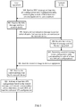
FIG. 7 is a schematic flowchart of a service data transmission method according to Embodiment 5 of the present invention; -
FIG. 8a is a schematic structural diagram of user equipment according to an embodiment of the present invention; -
FIG. 8b is a schematic structural diagram of another user equipment according to an embodiment of the present invention; -
FIG. 9a is a schematic structural diagram of a network device according to an embodiment of the present invention; and -
FIG. 9b is a schematic structural diagram of another network device according to an embodiment of the present invention. - To make the purpose, technical solutions, and advantages of the embodiments of the present invention clearer, the following describes the technical solutions of the embodiments of the present invention with reference to the accompanying drawings in the embodiments of the present invention.
- A network architecture and a service scenario described in the embodiments of the present invention are intended to describe the technical solutions in the embodiments of the present invention more clearly, and do not constitute any limitation on the technical solutions provided in the embodiments of the present invention. A person of ordinary skill in the art may understand that with evolution of network architectures and emergence of new service scenarios, the technical solutions provided in the embodiments of the present invention are also applicable to a similar technical problem.
- Referring to
FIG. 1, FIG. 1 is a schematic architectural diagram of a network to which an embodiment of the present invention is applied. The schematic architectural diagram of the network may represent a mobile communications wireless network in an LTE system, and includes an evolved UMTS terrestrial radio access network (Evolved UMTS Terrestrial Radio Access Network, E-UTRAN) that includes at least two eNBs, and at least two user equipments. The user equipment is a vehicle having a wireless communication function. The user equipment in this embodiment of the present invention is not limited to the vehicle, and may include other electronic devices having a wireless communication function, for example, a mobile phone, a tablet computer, and a wearable device. The user equipments may communicate with each other by using an air interface PC5, for example, transmitting information between vehicles and obtaining driving information of another vehicle. The user equipment and the eNB may communicate with each other by using an air interface Uu. The user equipment sends data to the eNB in an uplink direction, and the eNB sends data, a message, signaling, or the like to the user equipment in a downlink direction. - Based on the schematic architectural diagram of the network shown in
FIG. 1 , a service transmitted between the user equipments and a service transmitted between the user equipment and the eNB are V2X services. Different V2X services may have different periods and packet sizes, and a period and a packet size of a V2X service may also change. The service mentioned in this embodiment of the present invention may be a V2X service whose period and/or packet size may change, or may be another type of service whose period and/or packet size may change, or may be a service whose period and packet size is fixed. It can be understood that the services mentioned in this embodiment of the present invention are all to-be-transmitted services, and the to-be-transmitted service is a service of the user equipment or a service of a network device. - In this embodiment of the present invention, the user equipment may include but is not limited to the vehicle shown in
FIG. 1 , a mobile phone, a tablet computer, a wearable device, and the like. The network device may include but is not limited to the eNB shown inFIG. 1 and a base station. Based on the schematic architectural diagram of the network shown inFIG. 1 , the solutions provided in the embodiments of the present invention are described below with reference toFIG. 2 to FIG. 6 . - Referring to
FIG. 2, FIG. 2 is a schematic flowchart of a service data transmission method according to Embodiment 1 of the present invention. As shown inFIG. 2 , the method provided in Embodiment 1 of the present invention may include the following content of 201 to 204. - 201. A network device determines a control message, where the control message is used to indicate at least two SPS configurations.
- Specifically, before determining the control message, the network device establishes an RRC connection between the network device and user equipment, so that the network device and the user equipment may transmit information to each other.
- In a possible implementation, the user equipment detects whether there are at least two to-be-transmitted services, and when a detection result is yes, sends a service indication message to the network device by using an interface Uu between the user equipment and the network device. The service indication message includes a service period of each of the at least two to-be-transmitted services, and is used to instruct the network device to determine the control message based on the service period of each to-be-transmitted service and send the control message. It can be understood that the user equipment notifies the network device of the period required by the to-be-transmitted service by using the service indication message, so that the network device determines a period to be allocated to the to-be-transmitted service. Optionally, the user equipment sends one service indication message to the network device, and the service indication message includes a service period of each of the at least two to-be-transmitted services. Optionally, the user equipment sends at least two service indication messages to the network device, and each of the at least two service indication messages includes a service period of a corresponding to-be-transmitted service.
- The network device receives, by using the interface Uu between the user equipment and the network device, the service indication message sent by the user equipment, and obtains the service period of each of the at least two to-be-transmitted services. The network device determines the control message based on the service period of each to-be-transmitted service. The control message is used to indicate the at least two SPS configurations, and the at least two SPS configurations include SPS configurations required by the to-be-transmitted services. The SPS configuration may include configuration information such as an SPS period, an SPS resource, MCS configuration information, and a physical resource. Optionally, there is one control message, and the control message is used to indicate an SPS configuration that is allocated by the network device to each of the at least two to-be-transmitted services. Optionally, the control message includes at least two control sub-messages, and one control sub-message is corresponding to one SPS configuration. A quantity of the control sub-messages is the same as a quantity of the at least two SPS configurations. In other words, the quantity of the control sub-messages is the same as a quantity of the at least two to-be-transmitted services. In this way, each control sub-message is corresponding to one to-be-transmitted service.
- In another possible implementation, the network device directly obtains, by using the RRC connection between the network device and the user equipment, at least two to-be-transmitted services of the user equipment and a service period of each of the to-be-transmitted services, and determines the control message based on the service period of each to-be-transmitted service. Optionally, there is one control message, and the control message is used to indicate an SPS configuration that is allocated by the network device to each of the at least two to-be-transmitted services. Optionally, the control message includes at least two control sub-messages, and one control sub-message is corresponding to one SPS configuration. A quantity of the control sub-messages is the same as a quantity of the at least two SPS configurations. In other words, the quantity of the control sub-messages is the same as a quantity of the at least two to-be-transmitted services. In this way, each control sub-message is corresponding to one to-be-transmitted service.
- After the RRC connection between the network device and the user equipment is established, the network device sends an RRC message to the user equipment. The RRC message is used to indicate a pre-configured SPS period preset by the network device for the user equipment. Further, on the basis of the two foregoing possible implementations, the network device may determine the control information based on the RRC message. For example, the RRC message includes at least two pre-configured SPS periods, and the network device matches a service period of a to-be-transmitted service with the at least two pre-configured SPS periods to determine a pre-configured SPS period that matches the service period of the to-be-transmitted service, and uses the pre-configured SPS period as an SPS period that matches the service period of the to-be-transmitted service, and so on, so as to determine SPS periods that match the service periods of all of the at least two to-be-transmitted services. In this way, the control message is determined. Optionally, the network device directly determines, based on a service period of each to-be-transmitted service, an SPS period that matches the service period of the to-be-transmitted service, so as to determine the control message.
- The control message is a PDCCH message or an enhanced PDCCH message. The PDCCH message is control signaling on a PDCCH, and the enhanced PDCCH message is control signaling on an enhanced PDCCH. The enhanced PDCCH may be represented as EPDCCH. 202. The network device sends the control message to user equipment.
- Specifically, after determining the control message, the network device sends the control message to the user equipment by using the interface Uu between the user equipment and the network device.
- 203. The user equipment receives the control message sent by the network device.
- Specifically, the user equipment receives, by using the interface Uu between the user equipment and the network device, the control message sent by the network device.
- 204. The user equipment activates the at least two SPS configurations based on the control message, and transmits corresponding service data based on each of the at least two activated SPS configurations.
- Specifically, although the control message is used to indicate the at least two SPS configurations, the user equipment cannot directly obtain the SPS configurations in the control message when receiving the control message sent by the network device, and needs to first decode the control message. In addition, the control message merely indicates the at least two SPS configurations, but does not include the at least two SPS configurations. In other words, content included in the control message may indicate the at least two SPS configurations. The control message may include other control information in addition to indicating the at least two SPS configurations. After decoding the control message, the user equipment obtains the content, in the control message, that is used to indicate the at least two SPS configurations.
- In a possible implementation, the content included in the control message is a pre-configuration index corresponding to each of at least two SPS pre-configurations. In another possible implementation, the content included in the control message is an SPS period of each of the at least two SPS configurations, or is an SPS period of each of the at least two SPS configurations and a configuration index of each of the at least two SPS configurations. In still another possible implementation, the content included in the control message is a process identifier of a pre-configured SPS process of each of the at least two SPS configurations and an SPS period of each of the at least two SPS configurations. In yet another possible implementation, the content included in the control message is an SPS period of each of the at least two SPS configurations, or is an SPS period of each of the at least two SPS configurations and a configuration index of each of the at least two SPS configurations.
- The user equipment stores the at least two activated SPS configurations and transmits the corresponding service data by using the activated SPS configuration. The service data is data of a to-be-transmitted service. One SPS configuration is corresponding to one SPS period and one SPS resource. By using a to-be-transmitted service A as an example, the user equipment transmits data of the to-be-transmitted service A on an SPS resource of the to-be-transmitted service A based on an SPS period of the to-be-transmitted service A. The SPS resource may be a radio resource between any two or more user equipments, or may be a radio resource between the user equipment and the network device.
- In a possible implementation, by using the interface Uu between the user equipment and the network device, the user equipment sends/receives service data related to a to-be-transmitted service to/from the network device. In another possible implementation, by using an interface PC5 between user equipments, the user equipment sends/receives service data related to a to-be-transmitted service to/from another user equipment.
- When the user equipment supports simultaneous data transmission in two or more SPS periods, if there is an intersecting moment in SPS periods of two or more to-be-transmitted services, the user equipment may simultaneously transmit the two or more to-be-transmitted services at the intersecting moment without affecting one another, thereby improving resource utilization. When the user equipment does not support simultaneous data transmission in two or more SPS periods, if there is an intersecting moment in SPS periods of two or more to-be-transmitted services, the network device may adjust transmission of the two or more to-be-transmitted services by performing dynamic scheduling on the intersecting moment.
- After the user equipment activates the at least two SPS configurations based on the control message, the user equipment receives a release message sent by the network device. The release message is used to indicate a to-be-released target SPS configuration, and the user equipment releases the target SPS configuration based on the release message. The target SPS configuration is an activated SPS configuration. The release message is control signaling on a PDCCH or control signaling on an enhanced PDCCH. When preset SPS information includes at least two SPS pre-configurations and a pre-configuration index corresponding to each of the at least two SPS pre-configurations, the release message includes a pre-configuration index corresponding to the target SPS configuration. When preset SPS information includes a pre-configured SPS period, the release message includes an SPS period of the target SPS configuration or a configuration index corresponding to the target SPS configuration. When preset SPS information includes a pre-configured SPS period, at least two pre-configured SPS processes, and a process identifier of each of the at least two pre-configured SPS processes, the release message includes a process identifier of a pre-configured SPS process of the target SPS configuration. When preset SPS information includes or does not include a pre-configured SPS period, the control message includes an SPS period of the target SPS configuration or a configuration index corresponding to the target SPS configuration.
- The target SPS configuration is an SPS configuration of a service whose period and/or packet size changes. After the user equipment releases the target SPS configuration of the service, a new SPS configuration needs to be allocated to service data of the service. The user equipment receives an activation message sent by the network device, where the activation message includes a new SPS period required by service data corresponding to the target SPS configuration, and activates, based on the activation message, an SPS configuration that matches the new SPS period. In this way, the network device does not need to re-send the RRC message to reconfigure an SPS configuration for the service, thereby reducing a delay and improving processing efficiency.
- In this embodiment of the present invention, the network device determines the control message used to indicate the at least two SPS configurations, and sends the control message to the user equipment; and the user equipment receives the control message sent by the network device, activates the at least two SPS configurations based on the control message, and transmits the corresponding service data based on each of the at least two activated SPS configurations. In this way, at least two SPS configurations are simultaneously performed, thereby improving service data transmission efficiency.
- Referring to
FIG. 3, FIG. 3 is a schematic flowchart of a service data transmission method according to Embodiment 2 of the present invention. As shown inFIG. 3 , the method provided in Embodiment 2 of the present invention may include the following content of 301 to 308. In the method shown inFIG. 3 , for content the same as or similar to that in the method shown inFIG. 2 , refer to the related detailed description ofFIG. 2 . Details are not repeated herein. - 301. A network device sends an RRC message to user equipment, where the RRC message includes at least two pre-configurations and a configuration index corresponding to each of the at least two pre-configurations.
- Specifically, before sending the RRC message to the user equipment, the network device needs to establish an RRC connection between the network device and the user equipment, so that control signaling between the network device and the user equipment can be normally transmitted. After establishing the RRC connection, the network device sends the RRC message to the user equipment by using an interface Uu between the user equipment and the network device. The RRC message includes the at least two pre-configurations and the configuration index corresponding to each of the at least two pre-configurations. The pre-configuration includes only a pre-configured SPS period. The configuration index is used to identify the pre-configuration or a pre-configured SPS period in the pre-configuration. Referring to
FIG. 4, FIG. 4 is a schematic diagram of an example of an RRC message according to Embodiment 2 of the present invention. The RRC message includes three configuration indexes that are respectively a configuration index 1, a configuration index 2, and a configuration index 3. Pre-configured SPS periods corresponding to the configuration index 1 are shaded portions in a first row, and there are two blank cells between every two shaded cells. Pre-configured SPS periods corresponding to the configuration index 2 are shaded portions in a second row, and there are three blank cells between every two shaded cells. Pre-configured SPS periods corresponding to the configuration index 3 are shaded portions in the second row, and there are four blank cells between every two shaded cells. The specific RRC message is as follows:

- 302. The user equipment receives the RRC message sent by the network device.
- Specifically, the user equipment receives, by using the interface Uu between the user equipment and the network device, the RRC message sent by the network device. The user equipment may store the RRC message.
- 303. The user equipment sends a service indication message to the network device, where the service indication message includes a service period of each of at least two to-be-transmitted services.
- 304. The network device receives the service indication message sent by the user equipment. 305. The network device determines a control message, where the control message includes a pre-configuration index corresponding to each of at least two SPS pre-configurations.
- Optionally, the network device determines the control message based on the service period of each to-be-transmitted service in the service indication message. The control message is control signaling on a PDCCH or an EPDCCH. The control message includes the pre-configuration index corresponding to each of the at least two SPS pre-configurations. It can be understood that one to-be-transmitted service is corresponding to one SPS pre-configuration.
- In a possible implementation, a field is added to the control signaling on the PDCCH or the EPDCCH, to indicate a pre-configuration index that matches a service period of each to-be-transmitted service. Content of the control signaling to which the field is added is as follows, and the last row indicates the added field used to indicate the configuration index. A length of the pre-configuration index field may be determined based on a quantity of pre-configured SPS periods in the RRC message. For example, the length of the field is 2 bits, and it may be determined that there are four pre-configured SPS periods.
TPC command for scheduled PUSCH Cyclic shift DM RS Modulation and coding scheme and redundancy version Resource block assignment and hopping resource allocation HARQ process number Modulation and coding scheme Redundancy version Resource block assignment ... SPS configuration index - In another possible implementation, a new downlink control information (Downlink Control Information, DCI) format is defined for the control signaling. The new DCI format is used to carry information to which a configuration index is added. DCI has a plurality of formats, and is used to transmit different control information. In this embodiment of the present invention, a DCI format is defined for information to which a configuration index is added.
- 306. The network device sends the control message to the user equipment.
- 307. The user equipment receives the control message sent by the network device.
- 308. The user equipment activates at least two SPS configurations based on the control message, and transmits corresponding service data based on each of the at least two activated SPS configurations.
- Specifically, the user equipment decodes the control message based on a modulation and coding scheme (Modulation and Coding Scheme, MCS). The MCS may be included in the RRC message, or may be included in the control message. In the prior art, an MCS can be included only in an RRC message, which constitutes some specific limitations. After performing decoding, the user equipment searches for a pre-configured SPS period of each of the at least two SPS configurations based on the pre-configuration index, in the control message, that is corresponding to each SPS pre-configuration, and activates an SPS configuration that matches the pre-configured SPS period of each SPS configuration. The user equipment then transmits the corresponding service data by using the activated SPS configuration. For example, a to-be-transmitted service 1 is corresponding to an SPS configuration A, the SPS configuration A includes an SPS period A, an SPS resource a, and the like, and the user equipment transmits service data of the to-be-transmitted service 1 on the SPS resource a based on the SPS period A. In a possible implementation, by using the interface Uu between the user equipment and the network device, the user equipment sends/receives service data related to a to-be-transmitted service to/from the network device. In another possible implementation, by using an interface PC5 between user equipments, the user equipment sends/receives service data related to a to-be-transmitted service to/from another user equipment.
- When the user equipment supports simultaneous data transmission in two or more SPS periods, if there is an intersecting moment in SPS periods of two or more to-be-transmitted services, the user equipment may simultaneously transmit the two or more to-be-transmitted services at the intersecting moment without affecting one another, thereby improving resource utilization. For example, in
FIG. 4 , the pre-configured SPS periods corresponding to the configuration index 2 occupy a same subframe as the pre-configured SPS periods corresponding to the configuration index 3. The user equipment may perform transmission in the following manner.
- Black shaded cells indicate the pre-configured SPS periods corresponding to the configuration index 2, and gray shaded cells indicate the SPS configuration periods corresponding to the configuration index 3. In the same sub-frame, the user equipment may simultaneously transmit data corresponding to two to-be-transmitted services without affecting one another.
- After an SPS configuration is activated, if the SPS configuration is not used for service data transmission or the SPS configuration is used to transmit another service, the network device may send a release message to the user equipment to release the SPS configuration. When a period and/or a packet size of a to-be-transmitted service of the at least two to-be-transmitted services changes, the changed to-be-transmitted service is used as a target service. The network device sends a release message to the user equipment, and the user equipment receives the release message, and releases, based on the release message, an SPS configuration used for current transmission of the target service. After the SPS configuration is released, the network device may send an activation message to the user equipment. The activation message includes a new SPS period that matches a service period of the target service. The user equipment receives the activation message and activates, based on the activation message, an SPS configuration that matches the new SPS period of the target service. In this case, the SPS configuration corresponding to the new SPS period overrides the previously used SPS configuration.
- In this embodiment of the present invention, the RRC message includes the at least two pre-configurations and the at least two pre-configuration indexes, so as to overcome a prior-art limitation that an RRC message includes only one pre-configuration. In this way, SPS is more flexible, and signaling overheads can be reduced.
- Referring to
FIG. 5, FIG. 5 is a schematic flowchart of a service data transmission method according to Embodiment 3 of the present invention. As shown inFIG. 5 , the method provided in Embodiment 3 of the present invention may include the following content of 501 to 508. In the method shown inFIG. 5 , for content the same as or similar to that in the method shown inFIG. 2 orFIG. 3 , refer to the related detailed descriptions ofFIG. 2 orFIG. 3 . Details are not repeated herein. - 501. A network device sends an RRC message to user equipment, where the RRC message includes a pre-configured SPS period.
- Specifically, after establishing an RRC connection to the user equipment, the network device sends the RRC message to the user equipment. The RRC message includes the pre-configured SPS period, and there is one pre-configured SPS period, and a period value of the pre-configured SPS period may be relatively small. The specific RRC message is as follows:


- 502. The user equipment receives the RRC message sent by the network device.
- 503. The user equipment sends a service indication message to the network device, where the service indication message includes a service period of each of at least two to-be-transmitted services.
- 504. The network device receives the service indication message sent by the user equipment. 505. The network device determines a control message based on the service period of each to-be-transmitted service, where the control message includes an SPS period of each of at least two SPS configurations.
- Specifically, the value of the pre-configured SPS period is relatively small, and therefore the pre-configured SPS period may be defined to indicate at least two SPS periods. For example, it is specified that two bits may indicate four SPS periods, and when more SPS periods are required, more bits may be used.
- The network device matches the service period of each to-be-transmitted service against the pre-configured SPS period in the RRC message, to determine an SPS period that matches the service period of each to-be-transmitted service, so as to determine the control message. The control message includes the SPS period of each of the at least two SPS configurations. Optionally, the control message includes an SPS period of each of at least two SPS configurations and a configuration index of each of the at least two SPS configurations. In this case, the configuration index is in the control message, and the pre-configuration index in Embodiment 2 is in the RRC message. The control message is control signaling on a PDCCH or an EPDCCH.
- In a possible implementation, an SPS period field is added to the control signaling on the PDCCH or the EPDCCH, to indicate a to-be-activated or to-be-released SPS period. Content of the control signaling to which the field is added is as follows. The last two rows indicate added fields used to indicate an SPS period. Lengths of these two fields may be determined based on a quantity of SPS periods.
TPC command for scheduled PUSCH Cyclic shift DM RS Modulation and coding scheme and redundancy version Resource block assignment and hopping resource allocation HARQ process number Modulation and coding scheme Redundancy version Resource block assignment ... SPS period SPS configuration index (optional) - In another possible implementation, a new DCI format is defined for the control signaling. The new DCI format is used to carry an SPS period and other information; and optionally, the new DCI format is used to carry a configuration index.
- 506. The network device sends the control message to the user equipment.
- 507. The user equipment receives the control message sent by the network device.
- 508. The user equipment activates the at least two SPS configurations based on the control message, and transmits corresponding service data based on each of the at least two activated SPS configurations.
- Specifically, the user equipment decodes the control message based on an MCS. The MCS may be included in the RRC message, or may be included in the control message. After performing decoding, the user equipment activates an SPS configuration that matches the SPS period of each SPS configuration, and transmits corresponding service data by using the activated SPS configuration that matches the SPS period of each SPS configuration.
- In a possible implementation, by using an interface Uu between the user equipment and the network device, the user equipment sends/receives service data related to a to-be-transmitted service to/from the network device. In another possible implementation, by using an interface PC5 between user equipments, the user equipment sends/receives service data related to a to-be-transmitted service to/from another user equipment.
- When the user equipment supports simultaneous data transmission in two or more SPS periods, if there is an intersecting moment in SPS periods of two or more to-be-transmitted services, the user equipment may simultaneously transmit the two or more to-be-transmitted services at the intersecting moment without affecting one another, thereby improving resource utilization.
- After an SPS configuration is activated, if the SPS configuration is not used for service data transmission or the SPS configuration is used to transmit another service, the network device may send a release message to the user equipment to release the SPS configuration. When a period and/or a packet size of a to-be-transmitted service of the at least two to-be-transmitted services changes, the changed to-be-transmitted service is used as a target service. In a possible implementation, the network device sends a release message to the user equipment, and the user equipment receives the release message, and releases, based on the release message, an SPS configuration used for current transmission of the target service. After the SPS configuration is released, the network device may send an activation message to the user equipment. The activation message includes a new SPS period that matches a service period of the target service. The user equipment receives the activation message and activates, based on the activation message, an SPS configuration that matches the new SPS period of the target service. In this case, the SPS configuration corresponding to the new SPS period overrides the previously used SPS configuration. In another possible implementation, the network device sends an update message to the user equipment. The update message includes a to-be-updated target SPS period or a configuration index of a to-be-updated target SPS configuration. The user equipment activates, based on the update message, an SPS configuration that matches the target SPS period. The update message is control signaling on a PDCCH or an EPDCCH. The to-be-updated target SPS period is a new SPS period required by a target service whose period and/or packet size changes. In this embodiment of the present invention, the RRC message includes one pre-configured SPS period, and the control message indicates an SPS configuration required by an actual to-be-transmitted service. In this way, SPS is more flexible, and signaling overheads can be reduced.
- Referring to
FIG. 6, FIG. 6 is a schematic flowchart of a service data transmission method according to Embodiment 4 of the present invention. As shown inFIG. 6 , the method provided in Embodiment 4 of the present invention may include the following content of 601 to 608. In the method shown inFIG. 6 , for content the same as or similar to that in the method shown inFIG. 2 ,FIG. 3 , orFIG. 5 , refer to the related detailed descriptions ofFIG. 2 ,FIG. 3 , orFIG. 5 . Details are not repeated herein. - 601. A network device sends an RRC message to user equipment, where the RRC message includes a pre-configured SPS period, at least two pre-configured SPS processes, and a process identifier of each of the at least two pre-configured SPS processes.
- Specifically, after establishing an RRC connection to the user equipment, the network device sends the RRC message to the user equipment. The RRC message includes a pre-configured SPS period, at least two pre-configured SPS processes, and a process identifier of each of the at least two pre-configured SPS processes. There is one pre-configured SPS period, and a period value of the pre-configured SPS period may be relatively small. The specific RRC message is as follows:


- 602. The user equipment receives the RRC message sent by the network device.
- 603. The user equipment sends a service indication message to the network device, where the service indication message includes a service period of each of at least two to-be-transmitted services.
- 604. The network device receives the service indication message sent by the user equipment. 605. The network device determines a control message, where the control message includes a process identifier of a pre-configured SPS process of each of at least two SPS configurations and an SPS period of each of the at least two SPS configurations.
- Specifically, the value of the pre-configured SPS period is relatively small, and therefore the pre-configured SPS period may be defined to indicate at least two SPS periods, and an SPS period may be allocated to an SPS process based on a process identifier of the SPS process. For example, it is specified that two bits may indicate four SPS periods, and when more SPS periods are required, more bits may be used.
- The network device matches the service period of each to-be-transmitted service against the pre-configured SPS period in the RRC message, to determine an SPS period that matches the service period of each to-be-transmitted service, so as to determine the control message. The control message includes the process identifier of the pre-configured SPS process of each of the at least two SPS configurations and the SPS period of each of the at least two SPS configurations. The control message is control signaling on a PDCCH or an EPDCCH.
- In a possible implementation, an SPS period field and an SPS process identifier field are added to the control signaling on the PDCCH or the EPDCCH, to indicate a to-be-activated or to-be-released SPS period and a process identifier of an SPS process. Content of the control signaling to which the fields are added is as follows. The last two rows indicate the added fields used to indicate the SPS period and the process identifier of the SPS process. Lengths of these two fields may be determined based on a quantity of SPS periods.
TPC command for scheduled PUSCH Cyclic shift DM RS Modulation and coding scheme and redundancy version Resource block assignment and hopping resource allocation HARQ process number Modulation and coding scheme Redundancy version Resource block assignment ... SPS process id SPS period - In another possible implementation, a new DCI format is defined for the control signaling. The new DCI format is used to carry an SPS period, a process identifier of an SPS process, and other information.
- 606. The network device sends the control message to the user equipment.
- 607. The user equipment receives the control message sent by the network device.
- 608. The user equipment activates the at least two SPS configurations based on the control message, and transmits corresponding service data based on each of the at least two activated SPS configurations.
- Specifically, the user equipment decodes the control message based on an MCS. The MCS may be included in the RRC message, or may be included in the control message. After performing decoding, the user equipment activates, based on the process identifier of the pre-configured SPS process of each SPS configuration, an SPS configuration that matches the SPS period of each SPS configuration, and transmits corresponding service data by using the activated SPS configuration that matches the SPS period of each SPS configuration. The user equipment searches for an SPS period of each SPS configuration based on the process identifier of the pre-configured SPS process of each SPS configuration, so as to activate the SPS configuration that matches the SPS period of each SPS configuration.
- In a possible implementation, by using an interface Uu between the user equipment and the network device, the user equipment sends/receives service data related to a to-be-transmitted service to/from the network device. In another possible implementation, by using an interface PC5 between user equipments, the user equipment sends/receives service data related to a to-be-transmitted service to/from another user equipment.
- When the user equipment supports simultaneous data transmission in two or more SPS periods, if there is an intersecting moment in SPS periods of two or more to-be-transmitted services, the user equipment may simultaneously transmit the two or more to-be-transmitted services at the intersecting moment without affecting one another, thereby improving resource utilization. After an SPS configuration is activated, if the SPS configuration is not used for service data transmission or the SPS configuration is used to transmit another service, the network device may send a release message to the user equipment to release the SPS configuration. When a period and/or a packet size of a to-be-transmitted service of the at least two to-be-transmitted services changes, the changed to-be-transmitted service is used as a target service. In a possible implementation, the network device sends a release message to the user equipment, and the user equipment receives the release message, and releases, based on the release message, an SPS configuration used for current transmission of the target service. After the SPS configuration is released, the network device may send an activation message to the user equipment. The activation message includes a new SPS period that matches a service period of the target service. The user equipment receives the activation message and activates, based on the activation message, an SPS configuration that matches the new SPS period of the target service. In another possible implementation, the network device sends an update message to the user equipment. The update message includes a process identifier of a pre-configured SPS process of a target SPS configuration. The user equipment activates, based on the update message, an SPS configuration that matches an SPS period of the target SPS configuration. The user equipment searches for an SPS period of the target configuration based on the process identifier of the pre-configured SPS process of the target SPS configuration, so as to activate the SPS configuration that matches the SPS period of the target SPS configuration. The update message is control signaling on a PDCCH or an EPDCCH.
- In this embodiment of the present invention, the RRC message includes one pre-configured SPS period and at least two pre-configured SPS processes, and the control message indicates an SPS configuration required by an actual to-be-transmitted service. In this way, SPS is more flexible, and signaling overheads can be reduced.
- Referring to
FIG. 7, FIG. 7 is a schematic flowchart of a service data transmission method according to Embodiment 5 of the present invention. As shown inFIG. 7 , the method provided in Embodiment 5 of the present invention may include the following content of 701 to 704. In the method shown inFIG. 7 , for content the same as or similar to that in the method shown inFIG. 2 ,FIG. 3 ,FIG. 5 , orFIG. 6 , refer to the related detailed descriptions ofFIG. 2 ,FIG. 3 ,FIG. 5 , orFIG. 6 , Details are not repeated herein. - 701. A network device determines a control message, where the control message includes an SPS period of each of at least two SPS configurations.
- Specifically, when detecting that there are at least two to-be-transmitted services, user equipment sends a service indication message to the network device. The service indication message includes a service period of each of the at least two to-be-transmitted services.
- Before the user equipment sends the service indication message to the network device, the user equipment receives an RRC message sent by the network device. In this case, the RRC message includes or does not include a pre-configured SPS period, and the pre-configured SPS period is an SPS period allocated by a network device to user equipment in the prior art.
- The network device receives the service indication message sent by the user equipment, and determines, based on the service period of each to-be-transmitted service, an SPS period that matches the service period of each to-be-transmitted service, so as to determine the control message. The control message includes the control message includes the SPS period of each of the at least two SPS configurations, or the control message includes the SPS period of each of the at least two SPS configurations and a configuration index of each of the at least two SPS configurations. The control message is control signaling on a PDCCH or an EPDCCH.
- In a possible implementation, an SPS period field is added to the control signaling on the PDCCH or the EPDCCH, to indicate a to-be-activated or to-be-released SPS period and an optional configuration index. Content of the control signaling to which the field is added is as follows. The last two rows indicate added fields used to indicate an SPS period and an optional configuration index. Lengths of these two fields may be determined based on a quantity of SPS periods.
TPC command for scheduled PUSCH Cyclic shift DM RS Modulation and coding scheme and redundancy version Resource block assignment and hopping resource allocation HARQ process number Modulation and coding scheme Redundancy version Resource block assignment ... SPS period SPS config index (optional) - In another possible implementation, a new DCI format is defined for the control signaling. The new DCI format is used to carry an SPS period, a configuration index, and other information. 702. The network device sends the control message to user equipment.
- 703. The user equipment receives the control message sent by the network device.
- 704. The user equipment activates the at least two SPS configurations based on the control message, and transmits corresponding service data based on each of the at least two activated SPS configurations.
- Specifically, the user equipment decodes the control message based on an MCS. The MCS may be included in the RRC message, or may be included in the control message. After performing decoding, the user equipment activates an SPS configuration that matches the SPS period of each SPS configuration, and transmits corresponding service data by using the activated SPS configuration that matches the SPS period of each SPS configuration.
- In a possible implementation, by using an interface Uu between the user equipment and the network device, the user equipment sends/receives service data related to a to-be-transmitted service to/from the network device. In another possible implementation, by using an interface PC5 between user equipments, the user equipment sends/receives service data related to a to-be-transmitted service to/from another user equipment.
- When the user equipment supports simultaneous data transmission in two or more SPS periods, if there is an intersecting moment in SPS periods of two or more to-be-transmitted services, the user equipment may simultaneously transmit the two or more to-be-transmitted services at the intersecting moment without affecting one another, thereby improving resource utilization. After an SPS configuration is activated, if the SPS configuration is not used for service data transmission or the SPS configuration is used to transmit another service, the network device may send a release message to the user equipment to release the SPS configuration. When a period and/or a packet size of a to-be-transmitted service of the at least two to-be-transmitted services changes, the changed to-be-transmitted service is used as a target service. In a possible implementation, the network device sends a release message to the user equipment, and the user equipment receives the release message, and releases, based on the release message, an SPS configuration used for current transmission of the target service. After the SPS configuration is released, the network device may send an activation message to the user equipment. The activation message includes a new SPS period that matches a service period of the target service. The user equipment receives the activation message and activates, based on the activation message, an SPS configuration that matches the new SPS period of the target service. In another possible implementation, the network device sends an update message to the user equipment. The update message includes a to-be-updated target SPS period or a configuration index of a to-be-updated target SPS configuration. The user equipment activates, based on the update message, an SPS configuration that matches the target SPS period. The update message is control signaling on a PDCCH or an EPDCCH. The to-be-updated target SPS period is a new SPS period required by a target service whose period and/or packet size changes.
- In this embodiment of the present invention, the RRC message includes or does not include a pre-configured SPS period, and the control message indicates an SPS configuration required by an actual to-be-transmitted service. In this way, SPS is more flexible, and signaling overheads can be reduced.
- It should be noted that Embodiment 2 to Embodiment 5 are four parallel solutions, and any one of the solutions may be executed.
- The solutions in the embodiments of the present invention are mainly described from a perspective of interaction between devices. It can be understood that, to implement the foregoing functions, the devices such as the user equipment and the network device include corresponding hardware structures and/or software modules for implementing the functions. A person of ordinary skill in the art should easily be aware that the units and the algorithm steps in the examples described with reference to the embodiments disclosed in this specification can be implemented by hardware or a combination of hardware and computer software. Whether the functions are performed by hardware or in a manner of computer software driving hardware depends on particular applications and design constraints of the technical solutions. A person skilled in the art may use a different method to implement the described functions for each particular application, but it should not be considered that the implementation goes beyond the scope of the present invention.
- In the embodiments of the present invention, the user equipment, the network device, and the like may be divided into function units based on the foregoing method examples. For example, the function units may be obtained through division based on functions, or two or more functions may be integrated into one processing unit. The integrated unit may be implemented in a form of hardware, or may be implemented in a form of a software functional unit. It should be noted that the unit division in the embodiments of the present invention is an example and merely logical function division, and may be other division in actual implementation.
- When an integrated unit is used,
FIG. 8a shows a possible schematic structural diagram of the user equipment used in the foregoing embodiments. Theuser equipment 800 includes a receivingunit 801 and aprocessing unit 802. The receivingunit 801 is configured to support the user equipment in performing a receiving operation of the user equipment. For example, the receivingunit 801 is configured to support the user equipment in performing theprocess 203 inFIG. 2 , theprocess 302 and theprocess 307 inFIG. 3 , theprocess 502 and theprocess 507 inFIG. 5 , theprocess 602 and theprocess 607 inFIG. 6 , theprocess 703 inFIG. 7 , and/or another process of the technology described in this specification. Theprocessing unit 802 is configured to control and manage an operation of the user equipment. For example, theprocessing unit 802 is configured to support the user equipment in performing the process 204 inFIG. 2 , the process 308 inFIG. 3 , the process 508 inFIG. 5 , the process 704 inFIG. 7 , and/or another process of the technology described in this specification. Theuser equipment 800 further includes a sending unit that is not shown inFIG. 8a . The sending unit is configured to support the user equipment in performing a sending operation of the user equipment. For example, the sending unit is configured to support the user equipment in performing theprocess 303 inFIG. 3 , theprocess 503 inFIG. 5 , theprocess 603 inFIG. 6 , and/or another process of the technology described in this specification. Theuser equipment 800 may further include a storage unit that is not shown inFIG. 8a and that is configured to store program code and data of the user equipment. - The
processing unit 802 may be a processor or a controller. For example, theprocessing unit 802 may be a central processing unit (Central Processing Unit, CPU), a general-purpose processor, a digital signal processor (Digital Signal Processor, DSP), an application-specific integrated circuit (Application-Specific Integrated Circuit, ASIC), a field programmable gate array (Field Programmable Gate Array, FPGA) or another programmable logic device, a transistor logic device, a hardware device, or any combination thereof. The controller/processor may implement or execute various example logical blocks, modules, and circuits described with reference to content disclosed in the present invention. Alternatively, the processor may be a combination of processors implementing a computing function, for example, a combination of one or more microprocessors, or a combination of the DSP and a microprocessor. The storage unit may be a memory. - When the
processing unit 802 is a processor, the sending unit is a transmitter, the receivingunit 801 is a receiver, and the storage unit is a memory, the user equipment used in this embodiment of the present invention may be user equipment shown inFIG. 8b . - Referring to
FIG. 8b , theuser equipment 810 includes aprocessor 812, areceiver 813, atransmitter 814, and amemory 811. Optionally, theuser equipment 810 may further include abus 815. Optionally, thereceiver 813 and thetransmitter 814 may be combined as a transceiver. Thereceiver 813, thetransmitter 814, theprocessor 812, and thememory 811 may be connected to each other by using thebus 815. Thebus 815 may be a Peripheral Component Interconnect (Peripheral Component Interconnect, PCI for short) bus, an extended industry standard architecture (Extended Industry Standard Architecture, EISA for short) bus, or the like. Thebus 815 may be classified into an address bus, a data bus, a control bus, and the like. For ease of representation, only one thick line is used to represent the bus inFIG. 8b , but this does not mean that there is only one bus or only one type of bus. - When an integrated unit is used,
FIG. 9A shows a possible schematic structural diagram of the network device used in the foregoing embodiments. Thenetwork device 900 includes aprocessing unit 901 and a sendingunit 902. Theprocessing unit 901 is configured to control and manage an operation of the network device. For example, theprocessing unit 901 is configured to support the network device in performing theprocess 201 inFIG. 2 , the process 305 inFIG. 3 , the process 505 inFIG. 5 , the process 605 inFIG. 6 , the process 701 inFIG. 7 , and/or another process of the technology described in this specification. The sendingunit 902 is configured to support the network device in performing a sending operation of the network device. For example, the sendingunit 902 is configured to support the network device in performing the process 202 inFIG. 2 , the process 301 and the process 306 inFIG. 3 , and the process 501 and the process 506 inFIG. 5 , the process 601 and the process 606 inFIG. 6 , the process 701 inFIG. 7 , and/or another process of the technology described in this specification. Thenetwork device 900 may further include a receiving unit that is not shown inFIG. 9a . The receiving unit is configured to support the network device in performing a receiving operation of the network device. For example, the receiving unit is configured to support the network device in performing the process 304 inFIG. 3 , the process 504 inFIG. 5 , the process 604 inFIG. 6 , and/or another process of the technology described in this specification. Thenetwork device 900 may further include a storage unit that is not shown inFIG. 9a and that is configured to store program code and data of the network device. - The
processing unit 901 may be a processor or a controller. For example, theprocessing unit 901 may be a CPU, a general purpose processor, a DSP, an ASIC, an FPGA or another programmable logic device, a transistor logic device, a hardware component, or any combination thereof. The controller/processor may implement or execute various example logical blocks, modules, and circuits described with reference to content disclosed in the present invention. Alternatively, the processor may be a combination of processors implementing a computing function, for example, a combination of one or more microprocessors, or a combination of the DSP and a microprocessor. The receiving unit and the sendingunit 902 may be a transceiver, a transceiver circuit, a communications interface, or the like. The storage unit may be a memory. - When the
processing unit 901 is a processor, the receiving unit is a receiver, the sendingunit 902 is a transmitter, and the storage unit is a memory, the network device used in this embodiment of the present invention may be a network device shown inFIG. 9B . - Referring to
FIG. 9B , thenetwork device 910 includes aprocessor 912, atransmitter 913, areceiver 914, and amemory 911. Optionally, thenetwork device 910 may further include abus 915. Optionally, thetransmitter 913 and thereceiver 914 may be combined as a transceiver. Thetransmitter 913, thereceiver 914, theprocessor 912, and thememory 911 may be connected to each other by using thebus 915. Thebus 915 may be a Peripheral Component Interconnect bus, an extended industry standard structure bus, or the like. Thebus 915 may be classified into an address bus, a data bus, a control bus, and the like. For ease of representation, only one thick line is used to represent the bus inFIG. 9B , but this does not mean that there is only one bus or only one type of bus. - Methods or algorithm steps described with reference to the content disclosed in this embodiment of the present invention may be implemented by hardware, or may be implemented by a processor by executing a software instruction. The software instruction may include a corresponding software module. The software module may be stored in a random access memory (Random Access Memory, RAM), a flash memory, a read only memory (Read Only Memory, ROM), an erasable programmable read only memory (Erasable Programmable ROM, EPROM), an electrically erasable programmable read only memory (Electrically EPROM, EEPROM), a register, a hard disk, a removable hard disk, a compact disc read-only memory (CD-ROM), or any other form of storage medium well-known in the art. For example, a storage medium is coupled to a processor, so that the processor can read information from the storage medium or write information into the storage medium. Certainly, the storage medium may be a component of the processor. The processor and the storage medium may be located in the ASIC. In addition, the ASIC may be located in a core network interface device. Certainly, the processor and the storage medium may exist in the core network interface device as discrete components.
- A person skilled in the art should be aware that in the foregoing one or more examples, functions described in the embodiments of the present invention may be implemented by hardware, software, firmware, or any combination thereof. When the present invention is implemented by software, the foregoing functions may be stored in a computer-readable medium or transmitted as one or more instructions or code in the computer-readable medium. The computer-readable medium includes a computer storage medium and a communications medium. The communications medium includes any medium that enables a computer program to be transmitted from one place to another. The storage medium may be any available medium accessible to a general-purpose or dedicated computer.
- In the foregoing specific implementations, the objectives, technical solutions, and benefits of the embodiments of the present invention are further described in detail. It should be understood that the foregoing descriptions are merely specific implementations of the embodiments of the present invention, but are not intended to limit the protection scope of the embodiments of present invention. Any modification, equivalent replacement, or improvement made based on technical solutions of the embodiments of the present invention shall fall within the protection scope of the embodiments of the present invention.
Claims (15)
- A service data transmission method comprising:receiving (302, 502, 602, 703), by user equipment, a radio resource control RRC message that comprises preset semi-persistent scheduling SPS information and that is sent by a network device, wherein the preset SPS information is used to indicate a pre-configured SPS period, and the preset SPS information comprises at least two SPS pre-configurations and a pre-configuration index corresponding to each of the at least two SPS pre-configurations, and each of the at least two SPS pre-configurations comprises a pre-configured SPS period;receiving (203, 307, 507, 607, 703), by the user equipment, a control message sent by the network device, wherein the control message is used to indicate at least two SPS configurations, wherein the control message comprises the pre-configuration index corresponding to each of the at least two SPS pre-configurations;activating (308, 508, 608, 704), by the user equipment, the at least two SPS configurations based on the control message, wherein the activating, by the user equipment, the at least two SPS configurations based on the control message comprises:activating, by the user equipment, an SPS configuration that matches the pre-configured SPS period of each SPS configuration; andtransmitting (308, 508, 608, 704), by the user equipment, corresponding service data based on each of the at least two activated SPS configurations.
- The method according to claim 1, wherein the preset SPS information comprises a pre-configured SPS period, at least two pre-configured SPS processes, and a process identifier of each of the at least two pre-configured SPS processes.
- The method according to claim 1, wherein the activating, by the user equipment, the at least two SPS configurations based on the control message comprises:decoding, by the user equipment, the control message based on a modulation and coding scheme MCS;searching, by the user equipment, for a pre-configured SPS period of each of the at least two SPS configurations based on the pre-configuration index corresponding to each SPS pre-configuration.
- The method according to claim 3, after the transmitting, by the user equipment, corresponding service data based on each of the at least two activated SPS configurations, further comprising:receiving, by the user equipment, a release message sent by the network device, wherein the release message is used to indicate a to-be-released target SPS configuration; andreleasing, by the user equipment, the target SPS configuration based on the release message.
- The method according to claim 4, wherein the control message, the release message, are physical downlink control channel PDCCH messages or enhanced PDCCH messages.
- A service data transmission method comprising:sending (301, 501, 601), by a network device, an RRC message that comprises preset SPS information to user equipment, wherein the preset SPS information is used to indicate a pre-configured SPS period, wherein the preset SPS information comprises at least two SPS pre-configurations and a pre-configuration index corresponding to each of the at least two SPS pre-configurations, and each of the at least two SPS pre-configurations comprises a pre-configured SPS period;determining (305, 505, 605, 701), by the network device, a control message, wherein the control message is used to indicate at least two SPS configurations; and the control message comprises the pre-configuration index corresponding to each of the at least two SPS pre-configurations; andsending (202, 306, 506, 606, 702), by the network device, the control message to the user equipment, so that the user equipment activates the at least two SPS configurations based on the control message, and transmits corresponding service data based on each of the at least two activated SPS configurations.
- The method according to claim 6, wherein the preset SPS information comprises a pre-configured SPS period; and the control message comprises an SPS period of each of the at least two SPS configurations, or the control message comprises an SPS period of each of the at least two SPS configurations and a configuration index of each of the at least two SPS configurations.
- The method according to claim 6, wherein the preset SPS information comprises a pre-configured SPS period, at least two pre-configured SPS processes, and a process identifier of each of the at least two pre-configured SPS processes; and the control message comprises a process identifier of a pre-configured SPS process of each of the at least two SPS configurations and an SPS period of each of the at least two SPS configurations.
- The method according to claim 6, after the sending, by the network device, the control message to the user equipment, further comprising:
sending, by the network device, a release message to the user equipment, wherein the release message is used to indicate a to-be-released target SPS configuration, and the user equipment releases the target SPS configuration based on the release message. - The method according to claim
9, wherein the control message, the release message, are physical downlink control channel PDCCH messages or enhanced PDCCH messages. - User equipment comprising:a receiver (813), configured to receive an RRC message that comprises preset SPS information and that is sent by a network device, wherein the preset SPS information is used to indicate a pre-configured SPS period and the preset SPS information comprises at least two SPS pre-configurations and a pre-configuration index corresponding to each of the at least two SPS pre-configurations, and each of the at least two SPS pre-configurations comprises a pre-configured SPS period;the receiver (813) is further configured to receive a control message sent by the network device, wherein the control message is used to indicate at least two SPS configurations, wherein the control message comprises the pre-configuration index corresponding to each of the at least two SPS pre-configurations; anda processor (812), configured to activate the at least two SPS configurations based on the control message, and transmit corresponding service data based on each of the at least two activated SPS configurations, wherein the processor is specifically configured to activate an SPS configuration that matches the pre-configured SPS period of each SPS configuration.
- The user equipment according to claim 11, wherein the preset SPS information comprises a pre-configured SPS period, at least two pre-configured SPS processes, and a process identifier of each of the at least two pre-configured SPS processes.
- The user equipment according to claim 11, wherein the processor is specifically configured to decode the control message based on an MCS, search for a pre-configured SPS period of each of the at least two SPS configurations based on the pre-configuration index corresponding to each SPS pre-configuration, and activate an SPS configuration that matches the pre-configured SPS period of each SPS configuration.
- The user equipment according to claim 13, wherein
the receiver (813) is further configured to receive a release message sent by the network device, wherein the release message is used to indicate a to-be-released target SPS configuration; and
the processor (812) is further configured to release the target SPS configuration based on the release message. - The user equipment according to claim 14, wherein the control message, the release message, are physical downlink control channel PDCCH messages or enhanced PDCCH messages.
Applications Claiming Priority (1)
| Application Number | Priority Date | Filing Date | Title |
|---|---|---|---|
| PCT/CN2016/082138 WO2017193406A1 (en) | 2016-05-13 | 2016-05-13 | Service data transmission method, user equipment and network device |
Publications (3)
| Publication Number | Publication Date |
|---|---|
| EP3451774A1 EP3451774A1 (en) | 2019-03-06 |
| EP3451774A4 EP3451774A4 (en) | 2019-04-24 |
| EP3451774B1 true EP3451774B1 (en) | 2020-11-04 |
Family
ID=60267710
Family Applications (1)
| Application Number | Title | Priority Date | Filing Date |
|---|---|---|---|
| EP16901361.2A Active EP3451774B1 (en) | 2016-05-13 | 2016-05-13 | Service data transmission method and user equipment |
Country Status (4)
| Country | Link |
|---|---|
| US (2) | US11096209B2 (en) |
| EP (1) | EP3451774B1 (en) |
| CN (1) | CN109076570B (en) |
| WO (1) | WO2017193406A1 (en) |
Families Citing this family (9)
| Publication number | Priority date | Publication date | Assignee | Title |
|---|---|---|---|---|
| ES2877698T3 (en) | 2016-08-12 | 2021-11-17 | Beijing Xiaomi Mobile Software Co Ltd | Periodic Resource Allocation on a Wireless Network and Device |
| US11284413B2 (en) * | 2016-08-12 | 2022-03-22 | Beijing Xiaomi Mobile Software Co., Ltd. | Traffic type based scheduling in a wireless network and device |
| KR102381306B1 (en) * | 2016-11-03 | 2022-03-31 | 프라운호퍼 게젤샤프트 쭈르 푀르데룽 데어 안겐반텐 포르슝 에. 베. | User equipment, base station, wireless communication network, data signal and method for providing continuous SPS after enhanced SPS control and handover |
| US10772113B2 (en) * | 2017-02-06 | 2020-09-08 | Qualcomm Incorporated | Autonomous uplink transmission techniques using shared radio frequency spectrum |
| CN109565676B (en) * | 2017-05-05 | 2023-10-17 | 瑞典爱立信有限公司 | Method and apparatus for configuring semi-persistent scheduling |
| CN111867115B (en) * | 2019-04-30 | 2022-04-26 | 大唐移动通信设备有限公司 | Semi-persistent scheduling method, device, equipment and storage medium |
| CN111867117B (en) * | 2019-04-30 | 2022-04-29 | 大唐移动通信设备有限公司 | Method for activating/deactivating configuration, network equipment and terminal |
| CN116530168A (en) * | 2020-12-11 | 2023-08-01 | Oppo广东移动通信有限公司 | Semi-static scheduling method and device for MBS service, terminal equipment and network equipment |
| CN114339825A (en) * | 2021-11-26 | 2022-04-12 | 锐捷网络股份有限公司 | Semi-static scheduling method and device |
Family Cites Families (45)
| Publication number | Priority date | Publication date | Assignee | Title |
|---|---|---|---|---|
| US7124059B2 (en) * | 2000-10-17 | 2006-10-17 | Accenture Global Services Gmbh | Managing maintenance for an item of equipment |
| US6760128B2 (en) * | 2000-12-06 | 2004-07-06 | Eastman Kodak Company | Providing a payment schedule for utilizing stored images using a designated date |
| JP3952992B2 (en) * | 2003-06-03 | 2007-08-01 | ソニー株式会社 | Information processing apparatus, process control method, and computer program |
| EP2166804A1 (en) * | 2008-09-17 | 2010-03-24 | Panasonic Corporation | Deactivation of semi-persistent resource allocations in a mobile communication network |
| CN101677448B (en) * | 2008-09-19 | 2012-04-25 | 电信科学技术研究院 | A transmission method for data packet |
| US8223646B2 (en) * | 2008-09-19 | 2012-07-17 | Research In Motion Limited | Transport block size signaling for semi-persistent scheduling |
| KR100956828B1 (en) * | 2008-11-13 | 2010-05-11 | 엘지전자 주식회사 | A method and apparatus for indicating deactivation of semi-persistent scheduling |
| EP2214442B8 (en) * | 2009-02-02 | 2013-06-19 | Research In Motion Limited | Apparatus and method for coordinating the operations of discontinuous reception and the semi-persistent scheduling. |
| CN101854639A (en) * | 2009-03-31 | 2010-10-06 | 中兴通讯股份有限公司 | Resource scheduling method and user equipment |
| US8917659B2 (en) * | 2009-10-29 | 2014-12-23 | Lg Electronics Inc. | Method of transmitting warning message in multiple component carrier system |
| CN102158973B (en) * | 2010-02-11 | 2013-11-20 | 电信科学技术研究院 | Method, system and equipment for semi-duration dispatching, transmitting and processing |
| MY164719A (en) * | 2010-02-12 | 2018-01-30 | Interdigital Patent Holdings Inc | Method and apparatus for optimizing uplink random access channel transmission |
| WO2011137408A2 (en) * | 2010-04-30 | 2011-11-03 | Interdigital Patent Holdings, Inc. | Determination of carriers and multiplexing for uplink control information transmission |
| US8982743B2 (en) * | 2010-05-14 | 2015-03-17 | Qualcomm Incorporated | DAI designs for FDD carrier aggregation |
| JP5610861B2 (en) * | 2010-06-10 | 2014-10-22 | シャープ株式会社 | Mobile station apparatus, base station apparatus, radio communication system, radio communication method, and integrated circuit |
| ES2495429T3 (en) * | 2010-06-18 | 2014-09-17 | Mediatek Inc. | Resource allocation of the HARQ feedback channel for carrier aggregation in OFDMA systems |
| CN102056174B (en) * | 2010-12-16 | 2014-03-12 | 大唐移动通信设备有限公司 | Resource scheduling method and device and base station |
| CN102595600B (en) * | 2011-01-17 | 2014-12-31 | 华为技术有限公司 | Semi-static scheduling method, user equipment and network device |
| TW201320692A (en) * | 2011-08-10 | 2013-05-16 | Ind Tech Res Inst | Method for data transmission and base station and user equipment using the same |
| US8976764B2 (en) * | 2011-11-04 | 2015-03-10 | Blackberry Limited | Accommodating semi-persistent scheduling in heterogeneous networks with restricted subframe patterns |
| US10178657B2 (en) * | 2011-12-02 | 2019-01-08 | Innovative Sonic Corporation | Method and apparatus for reconfiguring SPS (semi-persistent) operation in a wireless communication system |
| WO2013131264A1 (en) * | 2012-03-08 | 2013-09-12 | Renesas Mobile Corporation | Group sps design for low cost mtc devices |
| GB2500896A (en) * | 2012-04-03 | 2013-10-09 | Renesas Mobile Corp | Synchronising a semi-persistent scheduling (SPS) function and a discontinuous reception and transmission (DRX/DTX) function |
| WO2013169173A1 (en) * | 2012-05-11 | 2013-11-14 | Telefonaktiebolaget L M Ericsson (Publ) | Extended semi-persistent scheduling (sps) configuration flexibility for infrequent dense resource allocations |
| WO2014015470A1 (en) * | 2012-07-23 | 2014-01-30 | Renesas Mobile Corporation | Vehicle gateway access in cellular network for vehicle communications |
| US9686772B2 (en) * | 2012-08-01 | 2017-06-20 | Qualcomm Incorporated | Methods and apparatus for coordinated multipoint (CoMP) communications |
| CN104620523B (en) * | 2012-08-10 | 2018-03-27 | Lg 电子株式会社 | The method and apparatus for supporting burst transfer in a wireless communication system |
| US20150181571A1 (en) * | 2012-08-15 | 2015-06-25 | Lg Electronics Inc. | Method monitoring pdcch based on drx and communication device thereof |
| WO2014092497A1 (en) | 2012-12-14 | 2014-06-19 | Lg Electronics Inc. | Method and apparatus for supporting transmission efficiency in a wireless communication system |
| US9609637B2 (en) * | 2012-12-21 | 2017-03-28 | Telefonaktiebolaget Lm Ericsson (Publ) | Override of multi-TTI scheduling messages |
| US9445365B2 (en) * | 2013-01-14 | 2016-09-13 | Apple Inc. | Reducing power consumption in voice over LTE terminals using semi persistent scheduling in connected discontinuous reception mode |
| EP3209053B1 (en) * | 2013-04-25 | 2022-12-07 | Huawei Technologies Co., Ltd. | Method for controlling uplink transmit power in inter-base station carrier aggregation, base station, and device |
| KR102058563B1 (en) * | 2013-08-07 | 2019-12-24 | 인터디지탈 패튼 홀딩스, 인크 | Distributed scheduling for device-to-device communication |
| US10314092B2 (en) * | 2013-08-16 | 2019-06-04 | Lg Electronics Inc. | Signal transmission method in device-to-device communication and apparatus therefor |
| CN104936302B (en) * | 2014-03-21 | 2018-08-10 | 上海诺基亚贝尔股份有限公司 | Method and apparatus for the semi-static continuous dispatching configuration in dual link |
| KR102241827B1 (en) * | 2014-05-16 | 2021-04-19 | 삼성전자 주식회사 | Method and apparatus for transmitting/receiving signal in mobilre communication system supporting a plurality of carriers |
| JP6568058B2 (en) * | 2014-05-30 | 2019-08-28 | シャープ株式会社 | Terminal apparatus, base station apparatus, and communication method |
| MX2017001081A (en) * | 2014-08-07 | 2017-07-19 | Intel Ip Corp | Resource allocation techniques for device-to-device (d2d) discovery. |
| MY186819A (en) * | 2014-09-01 | 2021-08-23 | Ericsson Telefon Ab L M | Conditional uplink radio resource utilization in a cellular network |
| US10631287B2 (en) * | 2014-09-26 | 2020-04-21 | Samsung Electronics Co., Ltd. | Method and apparatus for supporting multi-radio access technology |
| US10091631B2 (en) * | 2015-04-03 | 2018-10-02 | Lg Electronics Inc. | Method of transmitting and receiving signal in wireless communication system and apparatus therefor |
| CN106211332B (en) * | 2015-05-05 | 2021-08-17 | 中兴通讯股份有限公司 | Resource allocation method and device |
| US10477527B2 (en) | 2015-07-14 | 2019-11-12 | Qualcomm Incorporated | Semi-persistent scheduling mechanisms for vehicle-to-vehicle communication |
| EP3437402B1 (en) * | 2016-04-01 | 2021-03-03 | Panasonic Intellectual Property Corporation of America | Improved semi-persistent resource allocation for v2v traffic |
| CN107333334B (en) * | 2016-04-29 | 2020-01-31 | 普天信息技术有限公司 | Configuration method and device for semi-persistent scheduling of sidelink |
-
2016
- 2016-05-13 EP EP16901361.2A patent/EP3451774B1/en active Active
- 2016-05-13 CN CN201680085099.7A patent/CN109076570B/en active Active
- 2016-05-13 WO PCT/CN2016/082138 patent/WO2017193406A1/en unknown
- 2016-05-13 US US16/301,392 patent/US11096209B2/en active Active
-
2021
- 2021-07-23 US US17/383,746 patent/US11864194B2/en active Active
Non-Patent Citations (1)
| Title |
|---|
| None * |
Also Published As
| Publication number | Publication date |
|---|---|
| CN109076570A (en) | 2018-12-21 |
| CN109076570B (en) | 2021-01-29 |
| US11864194B2 (en) | 2024-01-02 |
| US11096209B2 (en) | 2021-08-17 |
| US20220046685A1 (en) | 2022-02-10 |
| US20200329489A1 (en) | 2020-10-15 |
| EP3451774A1 (en) | 2019-03-06 |
| WO2017193406A1 (en) | 2017-11-16 |
| EP3451774A4 (en) | 2019-04-24 |
Similar Documents
| Publication | Publication Date | Title |
|---|---|---|
| EP3451774B1 (en) | Service data transmission method and user equipment | |
| US10973045B2 (en) | Semi-persistent transmission method and apparatus in VIX communication | |
| EP3432662B1 (en) | Method and device for configuring and determining semi-persistent scheduling | |
| US10813090B2 (en) | Resource configuration method and device | |
| EP3448109B1 (en) | Scheduling method, apparatus, and system | |
| WO2018177109A1 (en) | Data transmission method and device, terminal, and storage medium | |
| US20200305139A1 (en) | Semi-persistent scheduling method and apparatus | |
| US20150195827A1 (en) | Fast access in v2v communication services by dynamic resources allocation | |
| WO2016202227A1 (en) | Selection and notification method and device for layer 2 link identifier | |
| WO2016155113A1 (en) | Group communication method, user equipment, base station device and system | |
| WO2020025042A1 (en) | Resource configuration method and terminal device | |
| EP3363134B1 (en) | Method and network node for managing harq attempts parameter for d2d links | |
| JP2018523347A (en) | Terminal device, network device, and data transmission method | |
| CN111867089B (en) | Resource allocation method and equipment | |
| CN110690944B (en) | Method and device for transmitting and determining priority of channel state information, storage medium and user equipment | |
| WO2017133417A1 (en) | Data channel subframe indication method and device | |
| WO2017049490A1 (en) | Scheduling assignment processing method, apparatus and device | |
| WO2017133334A1 (en) | Method and device for determining communication resource | |
| US20230095067A1 (en) | Communication method and communication device | |
| EP3634054A1 (en) | Method and apparatus for transmitting service data | |
| WO2017133013A1 (en) | Method and device for transmitting control signalling | |
| EP3562235A1 (en) | Service data transmission method, first communication node and base station | |
| CN107295643B (en) | Scheduling method, device and equipment | |
| EP3506695B1 (en) | Method and device for releasing semi-persistent scheduling resource | |
| WO2021212510A1 (en) | Communication method and device |
Legal Events
| Date | Code | Title | Description |
|---|---|---|---|
| STAA | Information on the status of an ep patent application or granted ep patent |
Free format text: STATUS: THE INTERNATIONAL PUBLICATION HAS BEEN MADE |
|
| PUAI | Public reference made under article 153(3) epc to a published international application that has entered the european phase |
Free format text: ORIGINAL CODE: 0009012 |
|
| STAA | Information on the status of an ep patent application or granted ep patent |
Free format text: STATUS: REQUEST FOR EXAMINATION WAS MADE |
|
| 17P | Request for examination filed |
Effective date: 20181129 |
|
| AK | Designated contracting states |
Kind code of ref document: A1 Designated state(s): AL AT BE BG CH CY CZ DE DK EE ES FI FR GB GR HR HU IE IS IT LI LT LU LV MC MK MT NL NO PL PT RO RS SE SI SK SM TR |
|
| AX | Request for extension of the european patent |
Extension state: BA ME |
|
| REG | Reference to a national code |
Ref country code: DE Ref legal event code: R079 Ref document number: 602016047499 Country of ref document: DE Free format text: PREVIOUS MAIN CLASS: H04W0072120000 Ipc: H04W0072040000 |
|
| RIC1 | Information provided on ipc code assigned before grant |
Ipc: H04W 72/04 20090101AFI20190312BHEP |
|
| A4 | Supplementary search report drawn up and despatched |
Effective date: 20190321 |
|
| DAV | Request for validation of the european patent (deleted) | ||
| DAX | Request for extension of the european patent (deleted) | ||
| GRAP | Despatch of communication of intention to grant a patent |
Free format text: ORIGINAL CODE: EPIDOSNIGR1 |
|
| STAA | Information on the status of an ep patent application or granted ep patent |
Free format text: STATUS: GRANT OF PATENT IS INTENDED |
|
| INTG | Intention to grant announced |
Effective date: 20200515 |
|
| GRAS | Grant fee paid |
Free format text: ORIGINAL CODE: EPIDOSNIGR3 |
|
| GRAA | (expected) grant |
Free format text: ORIGINAL CODE: 0009210 |
|
| STAA | Information on the status of an ep patent application or granted ep patent |
Free format text: STATUS: THE PATENT HAS BEEN GRANTED |
|
| AK | Designated contracting states |
Kind code of ref document: B1 Designated state(s): AL AT BE BG CH CY CZ DE DK EE ES FI FR GB GR HR HU IE IS IT LI LT LU LV MC MK MT NL NO PL PT RO RS SE SI SK SM TR |
|
| REG | Reference to a national code |
Ref country code: GB Ref legal event code: FG4D |
|
| REG | Reference to a national code |
Ref country code: CH Ref legal event code: EP |
|
| REG | Reference to a national code |
Ref country code: AT Ref legal event code: REF Ref document number: 1332473 Country of ref document: AT Kind code of ref document: T Effective date: 20201115 |
|
| REG | Reference to a national code |
Ref country code: IE Ref legal event code: FG4D |
|
| REG | Reference to a national code |
Ref country code: DE Ref legal event code: R096 Ref document number: 602016047499 Country of ref document: DE |
|
| REG | Reference to a national code |
Ref country code: AT Ref legal event code: MK05 Ref document number: 1332473 Country of ref document: AT Kind code of ref document: T Effective date: 20201104 |
|
| PG25 | Lapsed in a contracting state [announced via postgrant information from national office to epo] |
Ref country code: NO Free format text: LAPSE BECAUSE OF FAILURE TO SUBMIT A TRANSLATION OF THE DESCRIPTION OR TO PAY THE FEE WITHIN THE PRESCRIBED TIME-LIMIT Effective date: 20210204 Ref country code: PT Free format text: LAPSE BECAUSE OF FAILURE TO SUBMIT A TRANSLATION OF THE DESCRIPTION OR TO PAY THE FEE WITHIN THE PRESCRIBED TIME-LIMIT Effective date: 20210304 Ref country code: RS Free format text: LAPSE BECAUSE OF FAILURE TO SUBMIT A TRANSLATION OF THE DESCRIPTION OR TO PAY THE FEE WITHIN THE PRESCRIBED TIME-LIMIT Effective date: 20201104 Ref country code: GR Free format text: LAPSE BECAUSE OF FAILURE TO SUBMIT A TRANSLATION OF THE DESCRIPTION OR TO PAY THE FEE WITHIN THE PRESCRIBED TIME-LIMIT Effective date: 20210205 Ref country code: FI Free format text: LAPSE BECAUSE OF FAILURE TO SUBMIT A TRANSLATION OF THE DESCRIPTION OR TO PAY THE FEE WITHIN THE PRESCRIBED TIME-LIMIT Effective date: 20201104 |
|
| PG25 | Lapsed in a contracting state [announced via postgrant information from national office to epo] |
Ref country code: SE Free format text: LAPSE BECAUSE OF FAILURE TO SUBMIT A TRANSLATION OF THE DESCRIPTION OR TO PAY THE FEE WITHIN THE PRESCRIBED TIME-LIMIT Effective date: 20201104 Ref country code: BG Free format text: LAPSE BECAUSE OF FAILURE TO SUBMIT A TRANSLATION OF THE DESCRIPTION OR TO PAY THE FEE WITHIN THE PRESCRIBED TIME-LIMIT Effective date: 20210204 Ref country code: PL Free format text: LAPSE BECAUSE OF FAILURE TO SUBMIT A TRANSLATION OF THE DESCRIPTION OR TO PAY THE FEE WITHIN THE PRESCRIBED TIME-LIMIT Effective date: 20201104 Ref country code: LV Free format text: LAPSE BECAUSE OF FAILURE TO SUBMIT A TRANSLATION OF THE DESCRIPTION OR TO PAY THE FEE WITHIN THE PRESCRIBED TIME-LIMIT Effective date: 20201104 Ref country code: IS Free format text: LAPSE BECAUSE OF FAILURE TO SUBMIT A TRANSLATION OF THE DESCRIPTION OR TO PAY THE FEE WITHIN THE PRESCRIBED TIME-LIMIT Effective date: 20210304 Ref country code: AT Free format text: LAPSE BECAUSE OF FAILURE TO SUBMIT A TRANSLATION OF THE DESCRIPTION OR TO PAY THE FEE WITHIN THE PRESCRIBED TIME-LIMIT Effective date: 20201104 Ref country code: ES Free format text: LAPSE BECAUSE OF FAILURE TO SUBMIT A TRANSLATION OF THE DESCRIPTION OR TO PAY THE FEE WITHIN THE PRESCRIBED TIME-LIMIT Effective date: 20201104 |
|
| REG | Reference to a national code |
Ref country code: LT Ref legal event code: MG9D |
|
| PG25 | Lapsed in a contracting state [announced via postgrant information from national office to epo] |
Ref country code: HR Free format text: LAPSE BECAUSE OF FAILURE TO SUBMIT A TRANSLATION OF THE DESCRIPTION OR TO PAY THE FEE WITHIN THE PRESCRIBED TIME-LIMIT Effective date: 20201104 |
|
| PG25 | Lapsed in a contracting state [announced via postgrant information from national office to epo] |
Ref country code: SK Free format text: LAPSE BECAUSE OF FAILURE TO SUBMIT A TRANSLATION OF THE DESCRIPTION OR TO PAY THE FEE WITHIN THE PRESCRIBED TIME-LIMIT Effective date: 20201104 Ref country code: RO Free format text: LAPSE BECAUSE OF FAILURE TO SUBMIT A TRANSLATION OF THE DESCRIPTION OR TO PAY THE FEE WITHIN THE PRESCRIBED TIME-LIMIT Effective date: 20201104 Ref country code: SM Free format text: LAPSE BECAUSE OF FAILURE TO SUBMIT A TRANSLATION OF THE DESCRIPTION OR TO PAY THE FEE WITHIN THE PRESCRIBED TIME-LIMIT Effective date: 20201104 Ref country code: LT Free format text: LAPSE BECAUSE OF FAILURE TO SUBMIT A TRANSLATION OF THE DESCRIPTION OR TO PAY THE FEE WITHIN THE PRESCRIBED TIME-LIMIT Effective date: 20201104 Ref country code: EE Free format text: LAPSE BECAUSE OF FAILURE TO SUBMIT A TRANSLATION OF THE DESCRIPTION OR TO PAY THE FEE WITHIN THE PRESCRIBED TIME-LIMIT Effective date: 20201104 Ref country code: CZ Free format text: LAPSE BECAUSE OF FAILURE TO SUBMIT A TRANSLATION OF THE DESCRIPTION OR TO PAY THE FEE WITHIN THE PRESCRIBED TIME-LIMIT Effective date: 20201104 |
|
| REG | Reference to a national code |
Ref country code: DE Ref legal event code: R097 Ref document number: 602016047499 Country of ref document: DE |
|
| PG25 | Lapsed in a contracting state [announced via postgrant information from national office to epo] |
Ref country code: DK Free format text: LAPSE BECAUSE OF FAILURE TO SUBMIT A TRANSLATION OF THE DESCRIPTION OR TO PAY THE FEE WITHIN THE PRESCRIBED TIME-LIMIT Effective date: 20201104 |
|
| PLBE | No opposition filed within time limit |
Free format text: ORIGINAL CODE: 0009261 |
|
| STAA | Information on the status of an ep patent application or granted ep patent |
Free format text: STATUS: NO OPPOSITION FILED WITHIN TIME LIMIT |
|
| REG | Reference to a national code |
Ref country code: NL Ref legal event code: FP |
|
| 26N | No opposition filed |
Effective date: 20210805 |
|
| PG25 | Lapsed in a contracting state [announced via postgrant information from national office to epo] |
Ref country code: AL Free format text: LAPSE BECAUSE OF FAILURE TO SUBMIT A TRANSLATION OF THE DESCRIPTION OR TO PAY THE FEE WITHIN THE PRESCRIBED TIME-LIMIT Effective date: 20201104 |
|
| PG25 | Lapsed in a contracting state [announced via postgrant information from national office to epo] |
Ref country code: SI Free format text: LAPSE BECAUSE OF FAILURE TO SUBMIT A TRANSLATION OF THE DESCRIPTION OR TO PAY THE FEE WITHIN THE PRESCRIBED TIME-LIMIT Effective date: 20201104 |
|
| REG | Reference to a national code |
Ref country code: CH Ref legal event code: PL |
|
| PG25 | Lapsed in a contracting state [announced via postgrant information from national office to epo] |
Ref country code: LU Free format text: LAPSE BECAUSE OF NON-PAYMENT OF DUE FEES Effective date: 20210513 Ref country code: LI Free format text: LAPSE BECAUSE OF NON-PAYMENT OF DUE FEES Effective date: 20210531 Ref country code: MC Free format text: LAPSE BECAUSE OF FAILURE TO SUBMIT A TRANSLATION OF THE DESCRIPTION OR TO PAY THE FEE WITHIN THE PRESCRIBED TIME-LIMIT Effective date: 20201104 Ref country code: CH Free format text: LAPSE BECAUSE OF NON-PAYMENT OF DUE FEES Effective date: 20210531 |
|
| REG | Reference to a national code |
Ref country code: BE Ref legal event code: MM Effective date: 20210531 |
|
| PG25 | Lapsed in a contracting state [announced via postgrant information from national office to epo] |
Ref country code: IE Free format text: LAPSE BECAUSE OF NON-PAYMENT OF DUE FEES Effective date: 20210513 |
|
| PG25 | Lapsed in a contracting state [announced via postgrant information from national office to epo] |
Ref country code: IS Free format text: LAPSE BECAUSE OF FAILURE TO SUBMIT A TRANSLATION OF THE DESCRIPTION OR TO PAY THE FEE WITHIN THE PRESCRIBED TIME-LIMIT Effective date: 20210304 |
|
| PG25 | Lapsed in a contracting state [announced via postgrant information from national office to epo] |
Ref country code: BE Free format text: LAPSE BECAUSE OF NON-PAYMENT OF DUE FEES Effective date: 20210531 |
|
| PGFP | Annual fee paid to national office [announced via postgrant information from national office to epo] |
Ref country code: GB Payment date: 20230330 Year of fee payment: 8 |
|
| PG25 | Lapsed in a contracting state [announced via postgrant information from national office to epo] |
Ref country code: CY Free format text: LAPSE BECAUSE OF FAILURE TO SUBMIT A TRANSLATION OF THE DESCRIPTION OR TO PAY THE FEE WITHIN THE PRESCRIBED TIME-LIMIT Effective date: 20201104 |
|
| PGFP | Annual fee paid to national office [announced via postgrant information from national office to epo] |
Ref country code: NL Payment date: 20230417 Year of fee payment: 8 |
|
| PG25 | Lapsed in a contracting state [announced via postgrant information from national office to epo] |
Ref country code: HU Free format text: LAPSE BECAUSE OF FAILURE TO SUBMIT A TRANSLATION OF THE DESCRIPTION OR TO PAY THE FEE WITHIN THE PRESCRIBED TIME-LIMIT; INVALID AB INITIO Effective date: 20160513 |
|
| PGFP | Annual fee paid to national office [announced via postgrant information from national office to epo] |
Ref country code: IT Payment date: 20230412 Year of fee payment: 8 Ref country code: FR Payment date: 20230411 Year of fee payment: 8 Ref country code: DE Payment date: 20230331 Year of fee payment: 8 |
|
| PG25 | Lapsed in a contracting state [announced via postgrant information from national office to epo] |
Ref country code: MK Free format text: LAPSE BECAUSE OF FAILURE TO SUBMIT A TRANSLATION OF THE DESCRIPTION OR TO PAY THE FEE WITHIN THE PRESCRIBED TIME-LIMIT Effective date: 20201104 |