EP3449877B1 - Implant for use in a total ankle replacement system - Google Patents
Implant for use in a total ankle replacement system Download PDFInfo
- Publication number
- EP3449877B1 EP3449877B1 EP18200312.9A EP18200312A EP3449877B1 EP 3449877 B1 EP3449877 B1 EP 3449877B1 EP 18200312 A EP18200312 A EP 18200312A EP 3449877 B1 EP3449877 B1 EP 3449877B1
- Authority
- EP
- European Patent Office
- Prior art keywords
- implant
- soft tissue
- anchor
- tissue
- bone
- Prior art date
- Legal status (The legal status is an assumption and is not a legal conclusion. Google has not performed a legal analysis and makes no representation as to the accuracy of the status listed.)
- Active
Links
- 239000007943 implant Substances 0.000 title claims description 118
- 210000003423 ankle Anatomy 0.000 title claims description 24
- 210000004872 soft tissue Anatomy 0.000 claims description 77
- 210000000988 bone and bone Anatomy 0.000 claims description 61
- 210000001519 tissue Anatomy 0.000 claims description 37
- 210000004233 talus Anatomy 0.000 claims description 16
- 210000002303 tibia Anatomy 0.000 claims description 10
- 210000000544 articulatio talocruralis Anatomy 0.000 description 9
- 230000014759 maintenance of location Effects 0.000 description 6
- 230000003278 mimic effect Effects 0.000 description 4
- 230000008878 coupling Effects 0.000 description 3
- 238000010168 coupling process Methods 0.000 description 3
- 238000005859 coupling reaction Methods 0.000 description 3
- 239000000463 material Substances 0.000 description 3
- 239000004705 High-molecular-weight polyethylene Substances 0.000 description 2
- -1 for example Substances 0.000 description 2
- 230000037431 insertion Effects 0.000 description 2
- 238000003780 insertion Methods 0.000 description 2
- 238000009434 installation Methods 0.000 description 2
- 239000002184 metal Substances 0.000 description 2
- 229910052751 metal Inorganic materials 0.000 description 2
- 210000002435 tendon Anatomy 0.000 description 2
- 208000010392 Bone Fractures Diseases 0.000 description 1
- 229910000684 Cobalt-chrome Inorganic materials 0.000 description 1
- 239000004698 Polyethylene Substances 0.000 description 1
- 229910001069 Ti alloy Inorganic materials 0.000 description 1
- RTAQQCXQSZGOHL-UHFFFAOYSA-N Titanium Chemical compound [Ti] RTAQQCXQSZGOHL-UHFFFAOYSA-N 0.000 description 1
- 238000005299 abrasion Methods 0.000 description 1
- 230000003110 anti-inflammatory effect Effects 0.000 description 1
- 206010003246 arthritis Diseases 0.000 description 1
- 208000037873 arthrodesis Diseases 0.000 description 1
- 238000011882 arthroplasty Methods 0.000 description 1
- 210000000459 calcaneus Anatomy 0.000 description 1
- 239000000919 ceramic Substances 0.000 description 1
- 210000002082 fibula Anatomy 0.000 description 1
- 239000011521 glass Substances 0.000 description 1
- 238000002513 implantation Methods 0.000 description 1
- 230000003993 interaction Effects 0.000 description 1
- 210000003141 lower extremity Anatomy 0.000 description 1
- 239000007769 metal material Substances 0.000 description 1
- 210000003205 muscle Anatomy 0.000 description 1
- 201000008482 osteoarthritis Diseases 0.000 description 1
- 229940124583 pain medication Drugs 0.000 description 1
- 238000000554 physical therapy Methods 0.000 description 1
- 239000004033 plastic Substances 0.000 description 1
- 229920003023 plastic Polymers 0.000 description 1
- 229920000573 polyethylene Polymers 0.000 description 1
- 230000000717 retained effect Effects 0.000 description 1
- 239000005060 rubber Substances 0.000 description 1
- 238000001356 surgical procedure Methods 0.000 description 1
- 229910000811 surgical stainless steel Inorganic materials 0.000 description 1
- 239000010936 titanium Substances 0.000 description 1
- 229910052719 titanium Inorganic materials 0.000 description 1
- 210000001364 upper extremity Anatomy 0.000 description 1
Images

Classifications
-
- A—HUMAN NECESSITIES
- A61—MEDICAL OR VETERINARY SCIENCE; HYGIENE
- A61F—FILTERS IMPLANTABLE INTO BLOOD VESSELS; PROSTHESES; DEVICES PROVIDING PATENCY TO, OR PREVENTING COLLAPSING OF, TUBULAR STRUCTURES OF THE BODY, e.g. STENTS; ORTHOPAEDIC, NURSING OR CONTRACEPTIVE DEVICES; FOMENTATION; TREATMENT OR PROTECTION OF EYES OR EARS; BANDAGES, DRESSINGS OR ABSORBENT PADS; FIRST-AID KITS
- A61F2/00—Filters implantable into blood vessels; Prostheses, i.e. artificial substitutes or replacements for parts of the body; Appliances for connecting them with the body; Devices providing patency to, or preventing collapsing of, tubular structures of the body, e.g. stents
- A61F2/02—Prostheses implantable into the body
- A61F2/30—Joints
- A61F2/42—Joints for wrists or ankles; for hands, e.g. fingers; for feet, e.g. toes
- A61F2/4202—Joints for wrists or ankles; for hands, e.g. fingers; for feet, e.g. toes for ankles
-
- A—HUMAN NECESSITIES
- A61—MEDICAL OR VETERINARY SCIENCE; HYGIENE
- A61F—FILTERS IMPLANTABLE INTO BLOOD VESSELS; PROSTHESES; DEVICES PROVIDING PATENCY TO, OR PREVENTING COLLAPSING OF, TUBULAR STRUCTURES OF THE BODY, e.g. STENTS; ORTHOPAEDIC, NURSING OR CONTRACEPTIVE DEVICES; FOMENTATION; TREATMENT OR PROTECTION OF EYES OR EARS; BANDAGES, DRESSINGS OR ABSORBENT PADS; FIRST-AID KITS
- A61F2/00—Filters implantable into blood vessels; Prostheses, i.e. artificial substitutes or replacements for parts of the body; Appliances for connecting them with the body; Devices providing patency to, or preventing collapsing of, tubular structures of the body, e.g. stents
- A61F2/02—Prostheses implantable into the body
- A61F2/30—Joints
- A61F2/30721—Accessories
- A61F2/30749—Fixation appliances for connecting prostheses to the body
-
- A—HUMAN NECESSITIES
- A61—MEDICAL OR VETERINARY SCIENCE; HYGIENE
- A61F—FILTERS IMPLANTABLE INTO BLOOD VESSELS; PROSTHESES; DEVICES PROVIDING PATENCY TO, OR PREVENTING COLLAPSING OF, TUBULAR STRUCTURES OF THE BODY, e.g. STENTS; ORTHOPAEDIC, NURSING OR CONTRACEPTIVE DEVICES; FOMENTATION; TREATMENT OR PROTECTION OF EYES OR EARS; BANDAGES, DRESSINGS OR ABSORBENT PADS; FIRST-AID KITS
- A61F2/00—Filters implantable into blood vessels; Prostheses, i.e. artificial substitutes or replacements for parts of the body; Appliances for connecting them with the body; Devices providing patency to, or preventing collapsing of, tubular structures of the body, e.g. stents
- A61F2/02—Prostheses implantable into the body
- A61F2/30—Joints
- A61F2002/30001—Additional features of subject-matter classified in A61F2/28, A61F2/30 and subgroups thereof
- A61F2002/30316—The prosthesis having different structural features at different locations within the same prosthesis; Connections between prosthetic parts; Special structural features of bone or joint prostheses not otherwise provided for
- A61F2002/30329—Connections or couplings between prosthetic parts, e.g. between modular parts; Connecting elements
- A61F2002/30433—Connections or couplings between prosthetic parts, e.g. between modular parts; Connecting elements using additional screws, bolts, dowels, rivets or washers e.g. connecting screws
-
- A—HUMAN NECESSITIES
- A61—MEDICAL OR VETERINARY SCIENCE; HYGIENE
- A61F—FILTERS IMPLANTABLE INTO BLOOD VESSELS; PROSTHESES; DEVICES PROVIDING PATENCY TO, OR PREVENTING COLLAPSING OF, TUBULAR STRUCTURES OF THE BODY, e.g. STENTS; ORTHOPAEDIC, NURSING OR CONTRACEPTIVE DEVICES; FOMENTATION; TREATMENT OR PROTECTION OF EYES OR EARS; BANDAGES, DRESSINGS OR ABSORBENT PADS; FIRST-AID KITS
- A61F2/00—Filters implantable into blood vessels; Prostheses, i.e. artificial substitutes or replacements for parts of the body; Appliances for connecting them with the body; Devices providing patency to, or preventing collapsing of, tubular structures of the body, e.g. stents
- A61F2/02—Prostheses implantable into the body
- A61F2/30—Joints
- A61F2002/30001—Additional features of subject-matter classified in A61F2/28, A61F2/30 and subgroups thereof
- A61F2002/30316—The prosthesis having different structural features at different locations within the same prosthesis; Connections between prosthetic parts; Special structural features of bone or joint prostheses not otherwise provided for
- A61F2002/30329—Connections or couplings between prosthetic parts, e.g. between modular parts; Connecting elements
- A61F2002/30461—Connections or couplings between prosthetic parts, e.g. between modular parts; Connecting elements sutured, ligatured or stitched
-
- A—HUMAN NECESSITIES
- A61—MEDICAL OR VETERINARY SCIENCE; HYGIENE
- A61F—FILTERS IMPLANTABLE INTO BLOOD VESSELS; PROSTHESES; DEVICES PROVIDING PATENCY TO, OR PREVENTING COLLAPSING OF, TUBULAR STRUCTURES OF THE BODY, e.g. STENTS; ORTHOPAEDIC, NURSING OR CONTRACEPTIVE DEVICES; FOMENTATION; TREATMENT OR PROTECTION OF EYES OR EARS; BANDAGES, DRESSINGS OR ABSORBENT PADS; FIRST-AID KITS
- A61F2/00—Filters implantable into blood vessels; Prostheses, i.e. artificial substitutes or replacements for parts of the body; Appliances for connecting them with the body; Devices providing patency to, or preventing collapsing of, tubular structures of the body, e.g. stents
- A61F2/02—Prostheses implantable into the body
- A61F2/30—Joints
- A61F2002/30001—Additional features of subject-matter classified in A61F2/28, A61F2/30 and subgroups thereof
- A61F2002/30316—The prosthesis having different structural features at different locations within the same prosthesis; Connections between prosthetic parts; Special structural features of bone or joint prostheses not otherwise provided for
- A61F2002/30329—Connections or couplings between prosthetic parts, e.g. between modular parts; Connecting elements
- A61F2002/30462—Connections or couplings between prosthetic parts, e.g. between modular parts; Connecting elements retained or tied with a rope, string, thread, wire or cable
-
- A—HUMAN NECESSITIES
- A61—MEDICAL OR VETERINARY SCIENCE; HYGIENE
- A61F—FILTERS IMPLANTABLE INTO BLOOD VESSELS; PROSTHESES; DEVICES PROVIDING PATENCY TO, OR PREVENTING COLLAPSING OF, TUBULAR STRUCTURES OF THE BODY, e.g. STENTS; ORTHOPAEDIC, NURSING OR CONTRACEPTIVE DEVICES; FOMENTATION; TREATMENT OR PROTECTION OF EYES OR EARS; BANDAGES, DRESSINGS OR ABSORBENT PADS; FIRST-AID KITS
- A61F2/00—Filters implantable into blood vessels; Prostheses, i.e. artificial substitutes or replacements for parts of the body; Appliances for connecting them with the body; Devices providing patency to, or preventing collapsing of, tubular structures of the body, e.g. stents
- A61F2/02—Prostheses implantable into the body
- A61F2/30—Joints
- A61F2002/30001—Additional features of subject-matter classified in A61F2/28, A61F2/30 and subgroups thereof
- A61F2002/30667—Features concerning an interaction with the environment or a particular use of the prosthesis
- A61F2002/30688—Means for allowing passage or sliding of tendons or ligaments
-
- A—HUMAN NECESSITIES
- A61—MEDICAL OR VETERINARY SCIENCE; HYGIENE
- A61F—FILTERS IMPLANTABLE INTO BLOOD VESSELS; PROSTHESES; DEVICES PROVIDING PATENCY TO, OR PREVENTING COLLAPSING OF, TUBULAR STRUCTURES OF THE BODY, e.g. STENTS; ORTHOPAEDIC, NURSING OR CONTRACEPTIVE DEVICES; FOMENTATION; TREATMENT OR PROTECTION OF EYES OR EARS; BANDAGES, DRESSINGS OR ABSORBENT PADS; FIRST-AID KITS
- A61F2/00—Filters implantable into blood vessels; Prostheses, i.e. artificial substitutes or replacements for parts of the body; Appliances for connecting them with the body; Devices providing patency to, or preventing collapsing of, tubular structures of the body, e.g. stents
- A61F2/02—Prostheses implantable into the body
- A61F2/30—Joints
- A61F2/42—Joints for wrists or ankles; for hands, e.g. fingers; for feet, e.g. toes
- A61F2/4202—Joints for wrists or ankles; for hands, e.g. fingers; for feet, e.g. toes for ankles
- A61F2002/4205—Tibial components
-
- A—HUMAN NECESSITIES
- A61—MEDICAL OR VETERINARY SCIENCE; HYGIENE
- A61F—FILTERS IMPLANTABLE INTO BLOOD VESSELS; PROSTHESES; DEVICES PROVIDING PATENCY TO, OR PREVENTING COLLAPSING OF, TUBULAR STRUCTURES OF THE BODY, e.g. STENTS; ORTHOPAEDIC, NURSING OR CONTRACEPTIVE DEVICES; FOMENTATION; TREATMENT OR PROTECTION OF EYES OR EARS; BANDAGES, DRESSINGS OR ABSORBENT PADS; FIRST-AID KITS
- A61F2/00—Filters implantable into blood vessels; Prostheses, i.e. artificial substitutes or replacements for parts of the body; Appliances for connecting them with the body; Devices providing patency to, or preventing collapsing of, tubular structures of the body, e.g. stents
- A61F2/02—Prostheses implantable into the body
- A61F2/30—Joints
- A61F2/42—Joints for wrists or ankles; for hands, e.g. fingers; for feet, e.g. toes
- A61F2/4202—Joints for wrists or ankles; for hands, e.g. fingers; for feet, e.g. toes for ankles
- A61F2002/4207—Talar components
Definitions
- the present invention relates to an implant for use in a total ankle replacement system, in particular a talar implant.
- the invention also relates to a total ankle replacement system.
- An ankle joint may become severely damaged and painful due to arthritis, prior ankle surgery, bone fracture, osteoarthritis, and/or one or more additional conditions.
- Options for treating the injured ankle have included anti-inflammatory and pain medications, braces, physical therapy, joint arthrodesis, and total ankle replacement.
- Total ankle replacement generally comprises two components - tibial implant and a talar implant.
- the implants comprise articulation surfaces sized and configured to mimic the range of motion of the ankle joint.
- the talar implant may comprise an implant sized and configured to mimic the talar dome and the tibial implant may comprise an articulation surface sized and configured to mimic articulation of the tibia.
- An articulating component may be located between the talar implant and the tibial implant.
- An example of such a talar implant is disclosed in US 2011/218648 .
- Soft tissue around the ankle can also be comprised.
- soft tissue may be partially or completely disconnected from a bone prior to and/or during a total ankle replacement.
- soft tissue When performing an ankle replacement, soft tissue must be anchored back to the bone. If bone is not available, the soft tissue cannot be properly anchored and will continue to deteriorate.
- US 2012/185057 discloses a malleolar implant having a body provided with an outer flange within which the posterior tibial tendon can sit.
- US 5 888 203 discloses a prosthesis for upper and lower extremity arthroplasty, having a body provided with two through channels in which ligamentous means are received.
- US 2011/202138 discloses an implant having a body provided with an outer groove or trough in which the muscles and tendons can extend.
- the present invention is an implant as defined in claim 1.
- an implant in various embodiments, includes a body including an articulation surface and an opposed bone contact surface.
- the implant defines a predetermined thickness between the articulation surface and the bone contact surface.
- the body defines at least one anchor hole sized and configured to receive an anchor therethrough.
- the anchor is configured to couple soft tissue to the body.
- the anchors are coupled to soft tissue and passed through the at least one anchor hole to anchor the soft tissue to the body of the implant.
- a total ankle replacement system in various embodiments, includes a tibial implant sized and configured to couple to a resected tibia and a talar implant sized and configured to couple to a resected talus.
- the talar implant includes a body having an articulation surface and an opposed bone contact surface. The body defines a predetermined thickness between the articulation surface and the bone contact surface. The body defines at least one anchor hole sized and configured to receive an anchor therethrough. The anchor is configured to couple soft tissue to the body.
- an implant in various embodiments, includes a body having an articulation surface and an opposed bone contact surface.
- the body defines a predetermined thickness between the articulation surface and the bone contact surface.
- the body defines at least one tissue groove formed thereon sized and configured to receive soft tissue.
- the tissue groove extends at least a predetermined depth from the articulation surface into the body.
- the present disclosure generally provides an implant for use with a total ankle replacement system.
- the implant comprises a body having one or more anchor holes formed therethrough.
- the anchor holes are configured to receive an anchor and/or soft tissue therein to couple the soft tissue to the implant.
- a groove is formed on the talar implant to receive soft tissue therein.
- the implant provides a secure anchor to allow soft tissue to be positioned at an anatomically correct and/or desirable position with respect to the implant and a bone.
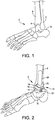
- FIG. 1 illustrates an anatomic view of an ankle joint 2.
- the ankle joint 2 comprises a talus 4 in contact with a tibia 6 and a fibula 8.
- a calcaneus 10 is located adjacent to the talus 4.
- the talus 4 and the tibia 6 may be resected, or cut, to allow insertion of a talar implant and a tibial implant.
- FIG. 2 illustrates the ankle joint 2 of FIG. 1 having a total ankle replacement system 12 inserted therein.
- the total ankle replacement system 12 comprises a talar implant 14 and a tibial implant 18.
- the talar implant 14 comprises a body 15 defining a talar articulation surface 16 (or talar dome).
- a stem 22 extends into the talus 4 to anchor the talar implant 14 to the talus 4.
- the tibial implant 18 is sized and configured for installation into the tibia 6.
- the tibial implant 18 comprises a body 19 having an articulation surface 20 and a tibial stem 24 extending into the tibia 6 to anchor the tibial implant 18.
- the talar joint surface 16 and the tibial joint surface 20 are mutually sized and configured to articulate.
- the joint surfaces 16, 20 replace the natural ankle joint surfaces, which are removed, to restore a range of motion that mimics the natural joint.
- One or more holes may be formed in the tibia and/or the talus prior to and during insertion of the tibial implant 18 or the talar implant 12.
- a hole is drilled starting in the bottom of the talus, extending through the talus and into the tibia.
- the hole may comprise, for example, a 6mm hole configured to receive the stem 24 of the tibial implant 18.
- the joint surfaces 16, 20 may be made of various materials, such as, for example, polyethylene, high molecular weight polyethylene (HMWPE), rubber, titanium, titanium alloys, chrome cobalt, surgical steel, and/or any other suitable metal, ceramic, sintered glass, artificial bone, and/or any combination thereof.
- the joint surfaces 16, 20 may comprise different materials.
- the tibial joint surface 20 may comprise a plastic or other non-metallic material and the talar joint surface 16 may comprise a metal surface.
- any suitable combination of materials may be used.
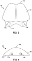
- FIG. 3 illustrates one example of a talar implant 102 having a plurality of anchor holes 110a, 110b formed therethrough.
- the talar implant 102 comprises a body 104 having an articulation surface 106 and an opposed bone contact surface (see FIG. 4 ).
- the body 104 has a predetermined thickness between the articulation surface 106 and the bone contact surface.
- the predetermined thickness can be configured based on the patient (e.g., patient-specific) and/or selected from a range of predetermined thicknesses.
- the articulation surface 106 is sized and configured to interface with an opposing joint surface of a total ankle replacement system.
- the articulation surface 106 is sized and configured to interface with a tibial joint surface, such as, for example, a tibial joint surface 20 as shown in FIG. 2 .
- the articulation surface 106 may be sized and configured to interface with an articulation implant located between a tibial portion of a total ankle replacement and the implant 106.
- the articulation surface 106 may comprise any suitable shape, such as, for example, a saddle shape (having two hemispheres) as illustrated in FIG. 3 or a dome shape.
- the bone contact surface comprises a surface configured to contact a resected bone section.
- the bone contact surface is configured to rest on and couple to a resected talus.
- the bone contact surface may comprise a planar surface, a concave surface, and/or any desirably shaped surface.
- the talar implant 102 comprises one or more anchor holes 110a, 110b formed therethrough.
- the anchor holes 110a, 110b may be formed through any suitable portion of the talar implant 102.
- the anchor holes 110a, 110b are formed through a neck flange 112 coupled to the body 104.
- the anchor holes 110a, 110b are formed through the body 104, for example, through a side of the body 104 and/or through the body 104 from the bone contact surface to the articulation surface 106.
- the anchor holes 110a, 110b are sized and configured to receive a soft tissue anchor therethrough.
- the anchor is coupled to soft tissue and couples the soft tissue to the implant 102.
- a suture (not shown) is passed through the anchor holes 110a, 110b and through soft tissue to attach the soft tissue to the talar implant 102.
- a needle may be coupled to the suture to pass the suture through soft tissue and to couple the soft tissue and the talar implant 102.
- Any suitable anchor such as, for example, sutures, staples, tissue tags, and/or any other suitable anchors may be used.
- the anchor holes are sized and configured to receive soft tissue therethrough.
- Soft tissue may be threaded through the anchor holes 110a, 110b to anchor the soft tissue to the implant 102.
- the soft tissue is retained in the anchor holes 110a, 110b by one or more retention devices, such as, for example, a suture, a tissue tag, a staple, and/or any other suitable retention device.
- soft tissue is passed through the anchor holes 110a, 110b and coupled to a bone to maintain the soft tissue in a fixed position.
- the anchor holes 110a, 110b are positioned to align the implant 102, the soft tissue, and a bone.
- the anchor holes 110a, 110b are configured to align soft tissue in an anatomically correct and/or desirable position when the soft tissue is coupled to the implant 102.
- the soft tissue may be anchored to and used to position the implant 102 prior to coupling the implant 102 to a bone.
- the implant 102 can comprise any number of anchor holes 110a, 110b, such as, for example, one anchor hole, two anchor holes, three anchor holes, and/or any other suitable number of anchor holes.
- a first subset of the anchor holes 110a, 110b may be used to anchor soft tissue to the implant 102 and a second subset of the anchor holes 110a, 110b may not be used.
- the anchor holes 110a, 110b are formed through an extension attached to the body 104 of the implant 102.
- the anchor holes 110a, 110b are formed through a neck flange 112 coupled to the body 104.
- the neck flange 112 is sized and configured to position attached soft tissue in an anatomically correct and/or desirable position with respect to the body 104.
- the soft tissue is positioned in a spaced arrangement with respect to the body 104 by the neck flange 112 to mimic the natural placement of the soft tissue and/or to prevent damage to the soft tissue caused by contact with the implant 102, the bone, and/or other structures.
- neck flange 12 extends from an anterior portion of the implant 102, it will be appreciated that one or more flanges 112 and/or other extensions may extend from any suitable portion of the body 104 (such as anterior, posterior, lateral, etc.) and may comprise any suitable number of anchor holes 110a, 110b formed therethrough.
- FIG. 4 illustrates one example of an implant 202 having a plurality of anchor holes 210a, 210b formed through a body 204 of the implant 202.
- the implant 202 is similar to the implant 102 discussed with respect to FIG. 1 , and similar description is not repeated herein.
- the implant 202 has a plurality of anchor holes 210a, 210b extending through the body 204 from an articulation surface 206 to a bone contact surface 208.
- the anchor holes 210a, 210b are sized and configured to receive one or more anchors therein.
- the anchors (not shown) are passed through soft tissue located near the implantation site of the implant 202 to couple the soft tissue to the body 204.
- the anchor holes 210a, 210b are sized and configured to receive soft tissue therethrough.
- the soft tissue may be anchored to the body 204 by a suitable retention device, such as, for example, one or more sutures, staples, tissue tags, and/or any other suitable retention device.
- one or more anchors and/or soft tissue may be coupled to the bone through the anchor holes 210a, 210b.
- anchor holes 210a, 210b are illustrated extending through a lower portion of the body 204, it will be appreciated that any number of anchor holes may be located through any portion of the body 204.
- the anchor holes 210a, 210b may be located in any suitable arrangement on the body 204.
- the anchor holes 210a, 210b are horizontally aligned along a bottom edge of the body 204.
- the anchor holes 210a, 210b may be horizontally aligned, vertically aligned, diagonally aligned, and/or randomly placed on the body 204.
- FIG. 5 illustrates one example of an implant 302 having one or more anchor holes 310a, 310b formed through a stem 314.
- the implant 302 is similar to the implants 104, 204 described with respect to FIGS. 3-4 , and similar description is not repeated herein.
- the implant 302 comprises a stem 314 extending from a bone contact surface 308 of the body 304.
- the stem 314 is sized and configured to be inserted into a hole formed in a bone, such as, for example, a hole formed in a resected talus during a total ankle replacement.
- the stem 314 comprises one or more anchor holes 310a, 310b.
- the anchor holes 310a, 310b are sized and configured to receive one or more sutures therethrough.
- the anchor holes 310a, 310b are sized and configured to receive soft tissue therethrough.
- the soft tissue is coupled to the body 304 by one or more retention devices, such as, for example, sutures, staples, tissue tags, and/or any other suitable retention device.
- soft tissue is coupled to the implant 302 by passing one or more anchors through the anchor holes 310a, 310b and the soft tissue.
- a stem 314 of the implant 302 is inserted into a hole formed in a resected talus and anchored to the bone by a bone screw inserted from a first side of the bone, through the fastener hole 316, and into a second side of the bone.
- the fastener hole 316 and the fastener 318 are configured to couple the implant 302 to a bone, such as, for example, a talus.
- the fastener hole 316 may be located through any portion of the implant 302, such as, for example, the stem 314 and/or the body 304.
- the fastener hole 316 may comprise internal threading for coupling to external threads of a fastener 318 inserted through the fastener hole 316.
- soft tissue is coupled to the stem 314 using the one or more anchor holes 310a, 310b prior to installation of the implant 302 in a bone.
- the soft tissue coupled to the stem 314 is drawn into the hole and coupled to the bone.
- one or more access holes are formed through the bone to allow soft tissue and/or anchors to be passed through holes 310a, 310b after the implant 302 is installed in the bone.
- FIG. 6 illustrates a cross-section of one embodiment of an implant 402 having a tissue groove 420 formed thereon.
- the implant 402 is similar to the implants 102, 202, 302 described in conjunction with FIGS. 3-5 , and similar description is not repeated herein.
- the implant 402 comprises a body 404 having a tissue groove 420 formed thereon.
- the tissue groove 420 is sized and configured to receive soft tissue therein.
- the tissue groove 420 is configured to position soft tissue in an anatomically correct and/or desirable position when the implant 402 is coupled to a bone.
- the tissue groove 420 is configured to position soft tissue in a position corresponding to a natural placement of the soft tissue in a joint, such as, for example, an ankle joint.
- the tissue groove 420 is configured to position the soft tissue such that the soft tissue is not damaged by contact with the implant 402 and/or a bone section.
- the tissue groove 420 is configured to protect soft tissue from damage.
- the tissue groove 420 extends from the articulation surface 406 a predetermined depth into the body 404 of the implant 402.
- the tissue groove 420 can comprise a depth such that soft tissue inserted into the tissue groove 420 to be located at or below the surface of the body 404.
- the tissue groove 420 protects soft tissue from damage due to rubbing, abrasions, and/or other interactions with a bone and/or an implant.
- a single tissue groove 420 is illustrated, it will be appreciated that multiple tissue grooves 420 may be formed on the body 404.
- the tissue groove 420 extends from the articulation surface 406 to the bone contact surface 408.
- soft tissue and/or anchors can be coupled to the bone through the tissue groove 420.
- the implant 402 includes a neck flange 412 coupled to the body 404.
- the neck flange 412 extends from an anterior portion of the body 404 and is configured to bear against a neck of a bone, such as, for example, a talus.
- the neck flange 418 includes one or more fastener holes 416a, 416b formed therethrough.
- one or more fasteners are inserted through the fastener holes 416a, 416b to anchor the implant 402 to a bone.
- a bone screw is inserted through each of the one or more fastener holes 416a, 416b to anchor the implant 402 to a bone.
- one or more anchor holes are formed through the body 404 and/or the neck flange 412.
- an implant in various embodiments, includes a body including an articulation surface and an opposed bone contact surface.
- the implant defines a predetermined thickness between the articulation surface and the bone contact surface.
- the body defines at least one anchor hole sized and configured to receive an anchor therethrough.
- the anchor is configured to couple soft tissue to the body.
- the anchors are coupled to soft tissue and passed through the at least one anchor hole to anchor the soft tissue to the body of the implant.
- the body defines one or more fastener holes therethrough sized and configured to receive a fastener.
- the at least one anchor hole can be sized and configured to receive soft tissue therethrough.
- the soft tissue is coupled to the anchor.
- the body comprises a stem extending from the bone contact surface of the body.
- the at least one anchor hole is formed through the stem.
- the body comprises a neck flange extending from an anterior portion of the body. The at least one anchor hole is formed through the neck flange.
- the body defines one or more tissue grooves formed thereon.
- the one or more tissue grooves can include a channel formed in the body, wherein the channel has a depth such that soft tissue placed in the channel is at or below an edge of the channel.
- the one or more tissue grooves can extend from an articulation surface to a bone contact surface.
- a total ankle replacement system in various embodiments, includes a tibial implant sized and configured to couple to a resected tibia and a talar implant sized and configured to couple to a resected talus.
- the talar implant includes a body having an articulation surface and an opposed bone contact surface. The body defines a predetermined thickness between the articulation surface and the bone contact surface. The body defines at least one anchor hole sized and configured to receive an anchor therethrough. The anchor is configured to couple soft tissue to the body.
- the body defines one or more fastener holes therethrough sized and configured to receive a fastener.
- the at least one anchor hole is sized and configured to receive soft tissue therethrough.
- the soft tissue can be coupled to the at least one suture.
- the body can include a stem extending from the bone contact surface. At least one of the anchor holes is formed through the stem.
- the body can include a neck flange extending from an anterior portion of the body. At least one of the anchor holes is formed through the neck flange.
- the body defines one or more tissue grooves formed thereon.
- the one or more tissue grooves can include a channel formed in the body having a depth such that soft tissue placed in the channel is at or below an edge of the channel.
- the one or more tissue grooves can extend from an articulation surface to a bone contact surface.
- an implant in various embodiments, includes a body having an articulation surface and an opposed bone contact surface.
- the body defines a predetermined thickness between the articulation surface and the bone contact surface.
- the body defines at least one tissue groove formed thereon sized and configured to receive soft tissue.
- the tissue groove extends at least a predetermined depth from the articulation surface into the body.
- the at least one groove can include a depth such that soft tissue placed in the groove is at or below an edge of the at least one groove.
- the body can further define at least one fastener hole formed therethrough.
- the body defines one or more anchor holes formed therethrough. The anchor holes are sized and configured to receive at least one suture therethrough.
Landscapes
- Health & Medical Sciences (AREA)
- Orthopedic Medicine & Surgery (AREA)
- Cardiology (AREA)
- Oral & Maxillofacial Surgery (AREA)
- Transplantation (AREA)
- Engineering & Computer Science (AREA)
- Biomedical Technology (AREA)
- Heart & Thoracic Surgery (AREA)
- Vascular Medicine (AREA)
- Life Sciences & Earth Sciences (AREA)
- Animal Behavior & Ethology (AREA)
- General Health & Medical Sciences (AREA)
- Public Health (AREA)
- Veterinary Medicine (AREA)
- Prostheses (AREA)
Description
- The present invention relates to an implant for use in a total ankle replacement system, in particular a talar implant. The invention also relates to a total ankle replacement system.
- An ankle joint may become severely damaged and painful due to arthritis, prior ankle surgery, bone fracture, osteoarthritis, and/or one or more additional conditions. Options for treating the injured ankle have included anti-inflammatory and pain medications, braces, physical therapy, joint arthrodesis, and total ankle replacement.
- Total ankle replacement generally comprises two components - tibial implant and a talar implant. The implants comprise articulation surfaces sized and configured to mimic the range of motion of the ankle joint. For example, the talar implant may comprise an implant sized and configured to mimic the talar dome and the tibial implant may comprise an articulation surface sized and configured to mimic articulation of the tibia. An articulating component may be located between the talar implant and the tibial implant. An example of such a talar implant is disclosed in
US 2011/218648 . - Soft tissue around the ankle can also be comprised. For example, soft tissue may be partially or completely disconnected from a bone prior to and/or during a total ankle replacement. When performing an ankle replacement, soft tissue must be anchored back to the bone. If bone is not available, the soft tissue cannot be properly anchored and will continue to deteriorate.
-
US 2012/185057 discloses a malleolar implant having a body provided with an outer flange within which the posterior tibial tendon can sit.US 5 888 203 discloses a prosthesis for upper and lower extremity arthroplasty, having a body provided with two through channels in which ligamentous means are received.US 2011/202138 discloses an implant having a body provided with an outer groove or trough in which the muscles and tendons can extend. - The present invention is an implant as defined in claim 1.
- In various embodiments, an implant is disclosed. The implant includes a body including an articulation surface and an opposed bone contact surface. The implant defines a predetermined thickness between the articulation surface and the bone contact surface. The body defines at least one anchor hole sized and configured to receive an anchor therethrough. The anchor is configured to couple soft tissue to the body. The anchors are coupled to soft tissue and passed through the at least one anchor hole to anchor the soft tissue to the body of the implant.
- In various embodiments, a total ankle replacement system is disclosed. The total ankle replacement system includes a tibial implant sized and configured to couple to a resected tibia and a talar implant sized and configured to couple to a resected talus. The talar implant includes a body having an articulation surface and an opposed bone contact surface. The body defines a predetermined thickness between the articulation surface and the bone contact surface. The body defines at least one anchor hole sized and configured to receive an anchor therethrough. The anchor is configured to couple soft tissue to the body.
- In various embodiments, an implant is disclosed. The implant includes a body having an articulation surface and an opposed bone contact surface. The body defines a predetermined thickness between the articulation surface and the bone contact surface. The body defines at least one tissue groove formed thereon sized and configured to receive soft tissue. The tissue groove extends at least a predetermined depth from the articulation surface into the body.
- The features and advantages of the present invention will be more fully disclosed in, or rendered obvious by the following detailed description of the preferred embodiments, which are to be considered together with the accompanying drawings wherein like numbers refer to like parts and further wherein:
-
FIG. 1 illustrates an anatomic view of an ankle joint. -
FIG. 2 illustrates one embodiment of an ankle joint having a total ankle replacement system therein. -
FIG. 3 illustrates one embodiment of an implant having one or more anchor holes formed therethrough. -
FIG. 4 illustrates one embodiment of an implant having one or more anchor holes formed through a body of the implant. -
FIG. 5 illustrates one embodiment of an implant having one or more anchor holes formed through a stem. -
FIG. 6 illustrates one embodiment of an implant having a soft tissue groove formed thereon. - The description of the exemplary embodiments is intended to be read in connection with the accompanying drawings, which are to be considered part of the entire written description. In the description, relative terms such as "lower," "upper," "horizontal," "vertical," "proximal," "distal," "above," "below," "up," "down," "top" and "bottom," as well as derivatives thereof (e.g., "horizontally," "downwardly," "upwardly," etc.) should be construed to refer to the orientation as then described or as shown in the drawing under discussion. These relative terms are for convenience of description and do not require that the apparatus be constructed or operated in a particular orientation. Terms concerning attachments, coupling and the like, such as "connected" and "interconnected," refer to a relationship wherein structures are secured or attached to one another either directly or indirectly through intervening structures, as well as both movable or rigid attachments or relationships, unless expressly described otherwise.
- In various embodiments, the present disclosure generally provides an implant for use with a total ankle replacement system. The implant comprises a body having one or more anchor holes formed therethrough. The anchor holes are configured to receive an anchor and/or soft tissue therein to couple the soft tissue to the implant. In some embodiments, a groove is formed on the talar implant to receive soft tissue therein. The implant provides a secure anchor to allow soft tissue to be positioned at an anatomically correct and/or desirable position with respect to the implant and a bone.
-
FIG. 1 illustrates an anatomic view of anankle joint 2. Theankle joint 2 comprises atalus 4 in contact with atibia 6 and afibula 8. Acalcaneus 10 is located adjacent to thetalus 4. In total ankle replacements, thetalus 4 and thetibia 6 may be resected, or cut, to allow insertion of a talar implant and a tibial implant.FIG. 2 illustrates theankle joint 2 ofFIG. 1 having a totalankle replacement system 12 inserted therein. - The total
ankle replacement system 12 comprises atalar implant 14 and atibial implant 18. Thetalar implant 14 comprises abody 15 defining a talar articulation surface 16 (or talar dome). Astem 22 extends into thetalus 4 to anchor thetalar implant 14 to thetalus 4. Thetibial implant 18 is sized and configured for installation into thetibia 6. Thetibial implant 18 comprises a body 19 having anarticulation surface 20 and atibial stem 24 extending into thetibia 6 to anchor thetibial implant 18. Thetalar joint surface 16 and thetibial joint surface 20 are mutually sized and configured to articulate. The joint surfaces 16, 20 replace the natural ankle joint surfaces, which are removed, to restore a range of motion that mimics the natural joint. One or more holes may be formed in the tibia and/or the talus prior to and during insertion of thetibial implant 18 or thetalar implant 12. For example, in some embodiments, a hole is drilled starting in the bottom of the talus, extending through the talus and into the tibia. The hole may comprise, for example, a 6mm hole configured to receive thestem 24 of thetibial implant 18. - The joint surfaces 16, 20 may be made of various materials, such as, for example, polyethylene, high molecular weight polyethylene (HMWPE), rubber, titanium, titanium alloys, chrome cobalt, surgical steel, and/or any other suitable metal, ceramic, sintered glass, artificial bone, and/or any combination thereof. The joint surfaces 16, 20 may comprise different materials. For example, the tibial
joint surface 20 may comprise a plastic or other non-metallic material and the talarjoint surface 16 may comprise a metal surface. Those skilled in the art will recognize that any suitable combination of materials may be used. -
FIG. 3 illustrates one example of atalar implant 102 having a plurality ofanchor holes talar implant 102 comprises abody 104 having anarticulation surface 106 and an opposed bone contact surface (seeFIG. 4 ). Thebody 104 has a predetermined thickness between thearticulation surface 106 and the bone contact surface. The predetermined thickness can be configured based on the patient (e.g., patient-specific) and/or selected from a range of predetermined thicknesses. Thearticulation surface 106 is sized and configured to interface with an opposing joint surface of a total ankle replacement system. For example, in one embodiment, thearticulation surface 106 is sized and configured to interface with a tibial joint surface, such as, for example, a tibialjoint surface 20 as shown inFIG. 2 . As another example, thearticulation surface 106 may be sized and configured to interface with an articulation implant located between a tibial portion of a total ankle replacement and theimplant 106. Thearticulation surface 106 may comprise any suitable shape, such as, for example, a saddle shape (having two hemispheres) as illustrated inFIG. 3 or a dome shape. The bone contact surface comprises a surface configured to contact a resected bone section. For example, in some embodiments, the bone contact surface is configured to rest on and couple to a resected talus. The bone contact surface may comprise a planar surface, a concave surface, and/or any desirably shaped surface. - The
talar implant 102 comprises one ormore anchor holes talar implant 102. For example, in the illustrated embodiment, theanchor holes neck flange 112 coupled to thebody 104. According to the invention, theanchor holes body 104, for example, through a side of thebody 104 and/or through thebody 104 from the bone contact surface to thearticulation surface 106. The anchor holes 110a, 110b are sized and configured to receive a soft tissue anchor therethrough. The anchor is coupled to soft tissue and couples the soft tissue to theimplant 102. For example, in some embodiments, a suture (not shown) is passed through theanchor holes talar implant 102. In some embodiments, a needle may be coupled to the suture to pass the suture through soft tissue and to couple the soft tissue and thetalar implant 102. Any suitable anchor, such as, for example, sutures, staples, tissue tags, and/or any other suitable anchors may be used. - According to the invention, the anchor holes are sized and configured to receive soft tissue therethrough. Soft tissue may be threaded through the
anchor holes implant 102. In some embodiments, the soft tissue is retained in theanchor holes anchor holes - In some embodiments, the
anchor holes implant 102, the soft tissue, and a bone. For example, in some embodiments, theanchor holes implant 102. As another example, the soft tissue may be anchored to and used to position theimplant 102 prior to coupling theimplant 102 to a bone. Although twoanchor holes implant 102 can comprise any number ofanchor holes anchor holes implant 102 and a second subset of theanchor holes - In some embodiments, the
anchor holes body 104 of theimplant 102. For example, in the illustrated embodiment, theanchor holes neck flange 112 coupled to thebody 104. Theneck flange 112 is sized and configured to position attached soft tissue in an anatomically correct and/or desirable position with respect to thebody 104. For example, in some embodiments, the soft tissue is positioned in a spaced arrangement with respect to thebody 104 by theneck flange 112 to mimic the natural placement of the soft tissue and/or to prevent damage to the soft tissue caused by contact with theimplant 102, the bone, and/or other structures. Although the illustratedneck flange 12 extends from an anterior portion of theimplant 102, it will be appreciated that one ormore flanges 112 and/or other extensions may extend from any suitable portion of the body 104 (such as anterior, posterior, lateral, etc.) and may comprise any suitable number ofanchor holes -
FIG. 4 illustrates one example of animplant 202 having a plurality ofanchor holes body 204 of theimplant 202. Theimplant 202 is similar to theimplant 102 discussed with respect toFIG. 1 , and similar description is not repeated herein. Theimplant 202 has a plurality ofanchor holes body 204 from anarticulation surface 206 to abone contact surface 208. In some embodiments, theanchor holes implant 202 to couple the soft tissue to thebody 204. In some embodiments, theanchor holes body 204 by a suitable retention device, such as, for example, one or more sutures, staples, tissue tags, and/or any other suitable retention device. In some embodiments, one or more anchors and/or soft tissue may be coupled to the bone through theanchor holes - Although two
anchor holes body 204, it will be appreciated that any number of anchor holes may be located through any portion of thebody 204. For example, in some embodiments, one anchor hole, two anchor holes, three anchor holes, and/or any number of anchor holes are formed through thebody 204. The anchor holes 210a, 210b may be located in any suitable arrangement on thebody 204. In the illustrated embodiment, theanchor holes body 204. In other embodiments, theanchor holes body 204. -
FIG. 5 illustrates one example of animplant 302 having one ormore anchor holes stem 314. Theimplant 302 is similar to theimplants FIGS. 3-4 , and similar description is not repeated herein. Theimplant 302 comprises astem 314 extending from abone contact surface 308 of thebody 304. Thestem 314 is sized and configured to be inserted into a hole formed in a bone, such as, for example, a hole formed in a resected talus during a total ankle replacement. Thestem 314 comprises one ormore anchor holes anchor holes anchor holes body 304 by one or more retention devices, such as, for example, sutures, staples, tissue tags, and/or any other suitable retention device. - In one embodiment, soft tissue is coupled to the
implant 302 by passing one or more anchors through theanchor holes stem 314 of theimplant 302 is inserted into a hole formed in a resected talus and anchored to the bone by a bone screw inserted from a first side of the bone, through thefastener hole 316, and into a second side of the bone. Thefastener hole 316 and thefastener 318 are configured to couple theimplant 302 to a bone, such as, for example, a talus. In some embodiments, thefastener hole 316 may be located through any portion of theimplant 302, such as, for example, thestem 314 and/or thebody 304. In some embodiments, thefastener hole 316 may comprise internal threading for coupling to external threads of afastener 318 inserted through thefastener hole 316. In some embodiments, soft tissue is coupled to thestem 314 using the one ormore anchor holes implant 302 in a bone. When thestem 314 is inserted into a reamed hole in the bone, the soft tissue coupled to thestem 314 is drawn into the hole and coupled to the bone. In some embodiments, one or more access holes are formed through the bone to allow soft tissue and/or anchors to be passed throughholes implant 302 is installed in the bone. -
FIG. 6 illustrates a cross-section of one embodiment of animplant 402 having atissue groove 420 formed thereon. Theimplant 402 is similar to theimplants FIGS. 3-5 , and similar description is not repeated herein. Theimplant 402 comprises abody 404 having atissue groove 420 formed thereon. Thetissue groove 420 is sized and configured to receive soft tissue therein. In some embodiments, thetissue groove 420 is configured to position soft tissue in an anatomically correct and/or desirable position when theimplant 402 is coupled to a bone. For example, in some embodiments, thetissue groove 420 is configured to position soft tissue in a position corresponding to a natural placement of the soft tissue in a joint, such as, for example, an ankle joint. In some embodiments, thetissue groove 420 is configured to position the soft tissue such that the soft tissue is not damaged by contact with theimplant 402 and/or a bone section. - In some embodiments, the
tissue groove 420 is configured to protect soft tissue from damage. Thetissue groove 420 extends from the articulation surface 406 a predetermined depth into thebody 404 of theimplant 402. For example, thetissue groove 420 can comprise a depth such that soft tissue inserted into thetissue groove 420 to be located at or below the surface of thebody 404. By placing tissue at or below the surface of thebody 404, thetissue groove 420 protects soft tissue from damage due to rubbing, abrasions, and/or other interactions with a bone and/or an implant. Although asingle tissue groove 420 is illustrated, it will be appreciated thatmultiple tissue grooves 420 may be formed on thebody 404. In some embodiments, thetissue groove 420 extends from thearticulation surface 406 to thebone contact surface 408. In some embodiments, soft tissue and/or anchors can be coupled to the bone through thetissue groove 420. - In some embodiments, the
implant 402 includes aneck flange 412 coupled to thebody 404. Theneck flange 412 extends from an anterior portion of thebody 404 and is configured to bear against a neck of a bone, such as, for example, a talus. The neck flange 418 includes one ormore fastener holes fastener holes implant 402 to a bone. For example, in some embodiments, a bone screw is inserted through each of the one ormore fastener holes implant 402 to a bone. In some embodiments, one or more anchor holes (not shown) are formed through thebody 404 and/or theneck flange 412. - In various embodiments, an implant is disclosed. The implant includes a body including an articulation surface and an opposed bone contact surface. The implant defines a predetermined thickness between the articulation surface and the bone contact surface. The body defines at least one anchor hole sized and configured to receive an anchor therethrough. The anchor is configured to couple soft tissue to the body. The anchors are coupled to soft tissue and passed through the at least one anchor hole to anchor the soft tissue to the body of the implant.
- In some embodiments, the body defines one or more fastener holes therethrough sized and configured to receive a fastener. The at least one anchor hole can be sized and configured to receive soft tissue therethrough. The soft tissue is coupled to the anchor. In some embodiments, the body comprises a stem extending from the bone contact surface of the body. The at least one anchor hole is formed through the stem. In some embodiments, the body comprises a neck flange extending from an anterior portion of the body. The at least one anchor hole is formed through the neck flange.
- In some embodiments, the body defines one or more tissue grooves formed thereon. The one or more tissue grooves can include a channel formed in the body, wherein the channel has a depth such that soft tissue placed in the channel is at or below an edge of the channel. The one or more tissue grooves can extend from an articulation surface to a bone contact surface.
- In various embodiments, a total ankle replacement system is disclosed. The total ankle replacement system includes a tibial implant sized and configured to couple to a resected tibia and a talar implant sized and configured to couple to a resected talus. The talar implant includes a body having an articulation surface and an opposed bone contact surface. The body defines a predetermined thickness between the articulation surface and the bone contact surface. The body defines at least one anchor hole sized and configured to receive an anchor therethrough. The anchor is configured to couple soft tissue to the body.
- In some embodiments, the body defines one or more fastener holes therethrough sized and configured to receive a fastener. The at least one anchor hole is sized and configured to receive soft tissue therethrough. The soft tissue can be coupled to the at least one suture. The body can include a stem extending from the bone contact surface. At least one of the anchor holes is formed through the stem. The body can include a neck flange extending from an anterior portion of the body. At least one of the anchor holes is formed through the neck flange.
- In some embodiments, the body defines one or more tissue grooves formed thereon. The one or more tissue grooves can include a channel formed in the body having a depth such that soft tissue placed in the channel is at or below an edge of the channel. The one or more tissue grooves can extend from an articulation surface to a bone contact surface.
- In various embodiments, an implant is disclosed. The implant includes a body having an articulation surface and an opposed bone contact surface. The body defines a predetermined thickness between the articulation surface and the bone contact surface. The body defines at least one tissue groove formed thereon sized and configured to receive soft tissue. The tissue groove extends at least a predetermined depth from the articulation surface into the body.
- The at least one groove can include a depth such that soft tissue placed in the groove is at or below an edge of the at least one groove. The body can further define at least one fastener hole formed therethrough. In some embodiments, the body defines one or more anchor holes formed therethrough. The anchor holes are sized and configured to receive at least one suture therethrough.
- Although the subject matter has been described in terms of exemplary embodiments, it is not limited thereto. Rather, the appended claims should be construed broadly, to include other variants and embodiments, which may be made by those skilled in the art. Features of any of the described embodiments may be combined with features of any of the other described embodiments and be within the scope of the invention as defined by the appended claims.
Claims (11)
- An implant for use in a total ankle replacement system, the implant (14; 102; 202; 302; 402) comprising a body (104; 204; 304; 404) comprising an articulation surface (106; 206; 306; 406) and an opposed bone contact surface (208; 308; 408) and at least one tissue groove (420) defined by the body, the at least one tissue groove being sized and configured to receive soft tissue therein and position the soft tissue in an anatomically desirable position when the implant is coupled to a bone, characterized in that the body (104; 204; 304; 404) further defines one or more anchor holes (110a, 110b; 210a, 210b; 310a, 310b) which are configured to receive soft tissue therethrough.
- The implant of claim 1, wherein the at least one tissue groove (420) comprises a channel formed in the body (404), and wherein the channel has a depth such that soft tissue placed in the channel is at or below an edge of the channel.
- The implant of claim 1 or claim 2, wherein the at least one tissue groove (420) extends from the articulation surface (406) to the bone contact surface (408).
- The implant of any preceding claim, wherein the at least one tissue groove (420) extends a predetermined depth from the articulation surface (406) into the body (404).
- The implant of any preceding claim, wherein the body (104; 404) comprises a neck flange (112; 412) extending from the bone contact surface (408) of the body.
- The implant of claim 5, wherein the neck flange (412) defines one or more fastener holes (416a; 416b), each of the one or more fastener holes sized and configured to receive a fastener to anchor the implant (402) to a bone.
- The implant of claim 6, wherein the fastener is a bone screw.
- The implant of any preceding claim, wherein the one or more anchor holes (110a, 110b; 210a, 210b; 310a, 310b) are configured to receive an anchor to retain the soft tissue.
- The implant of claim 8, wherein the anchor comprises a suture, a staple, and/or a tissue tag.
- The implant of any preceding claim, wherein the at least tissue groove (420) is configured to position the soft tissue in a position corresponding to a natural placement of the soft tissue in a joint.
- A total ankle replacement system, comprising:a tibial implant (18) sized and configured to couple to a resected tibia (6); anda talar implant (14; 102; 202; 302; 402) sized and configured to couple to a resected talus (4), the talar implant being according to any one of claims 1 to 10.
Applications Claiming Priority (2)
| Application Number | Priority Date | Filing Date | Title |
|---|---|---|---|
| US14/835,184 US20170056188A1 (en) | 2015-08-25 | 2015-08-25 | Total ankle talar prosthesis with anchor holes and grooves |
| EP16161905.1A EP3135251B1 (en) | 2015-08-25 | 2016-03-23 | Talar implant and total ankle replacement system comprising such a talar implant |
Related Parent Applications (2)
| Application Number | Title | Priority Date | Filing Date |
|---|---|---|---|
| EP16161905.1A Division-Into EP3135251B1 (en) | 2015-08-25 | 2016-03-23 | Talar implant and total ankle replacement system comprising such a talar implant |
| EP16161905.1A Division EP3135251B1 (en) | 2015-08-25 | 2016-03-23 | Talar implant and total ankle replacement system comprising such a talar implant |
Publications (2)
| Publication Number | Publication Date |
|---|---|
| EP3449877A1 EP3449877A1 (en) | 2019-03-06 |
| EP3449877B1 true EP3449877B1 (en) | 2019-10-09 |
Family
ID=55588168
Family Applications (2)
| Application Number | Title | Priority Date | Filing Date |
|---|---|---|---|
| EP16161905.1A Not-in-force EP3135251B1 (en) | 2015-08-25 | 2016-03-23 | Talar implant and total ankle replacement system comprising such a talar implant |
| EP18200312.9A Active EP3449877B1 (en) | 2015-08-25 | 2016-03-23 | Implant for use in a total ankle replacement system |
Family Applications Before (1)
| Application Number | Title | Priority Date | Filing Date |
|---|---|---|---|
| EP16161905.1A Not-in-force EP3135251B1 (en) | 2015-08-25 | 2016-03-23 | Talar implant and total ankle replacement system comprising such a talar implant |
Country Status (6)
| Country | Link |
|---|---|
| US (1) | US20170056188A1 (en) |
| EP (2) | EP3135251B1 (en) |
| JP (1) | JP2017042588A (en) |
| CN (1) | CN106473842A (en) |
| AU (1) | AU2016202925B2 (en) |
| CA (2) | CA2924192C (en) |
Families Citing this family (3)
| Publication number | Priority date | Publication date | Assignee | Title |
|---|---|---|---|---|
| AU2016400080B2 (en) * | 2016-03-28 | 2019-10-17 | Wright Medical Technology, Inc. | Anterior resurfacing talar plate |
| WO2020013901A2 (en) | 2018-04-24 | 2020-01-16 | Paragon 28, Inc. | Implants and methods of use and assembly |
| TWI786139B (en) | 2018-06-22 | 2022-12-11 | 財團法人工業技術研究院 | Artificial joint |
Family Cites Families (16)
| Publication number | Priority date | Publication date | Assignee | Title |
|---|---|---|---|---|
| FR2705559B1 (en) * | 1993-05-28 | 1995-08-04 | Lafosse Laurent | Joint finger to shield prosthesis. |
| US5702468A (en) * | 1995-03-09 | 1997-12-30 | Uresil Corporation | Carpal bone biaxially restrained prosthesis |
| US6673116B2 (en) * | 1999-10-22 | 2004-01-06 | Mark A. Reiley | Intramedullary guidance systems and methods for installing ankle replacement prostheses |
| US8052756B2 (en) * | 2002-10-24 | 2011-11-08 | Biomet Manufacturing Corp. | Method and apparatus for wrist arthroplasty |
| US7722676B2 (en) * | 2003-02-05 | 2010-05-25 | Wright Medical Technology, Inc. | Articulating implant system |
| DK1658023T3 (en) * | 2003-08-27 | 2007-06-11 | Link Waldemar Gmbh Co | Ankle joint endoprosthesis |
| AT502926B1 (en) * | 2004-11-08 | 2011-04-15 | Alphamed Medizintechnik Fischer Gmbh | ANKLE PROSTHESIS ELEMENTS |
| US20060247788A1 (en) * | 2005-03-31 | 2006-11-02 | The Regents Of The University Of California | Total ankle arthroplasty |
| WO2007103826A2 (en) * | 2006-03-02 | 2007-09-13 | Talus Medical, Inc. | Bone prosthesis |
| US20090105840A1 (en) * | 2007-10-18 | 2009-04-23 | Inbone Technologies, Inc. | Fibular stiffener and bony defect replacer |
| EP2781197B8 (en) * | 2009-08-27 | 2018-06-27 | The Foundry, LLC | Apparatus for force redistribution in articular joints |
| US8303667B2 (en) * | 2010-03-02 | 2012-11-06 | Alastair Younger | Fastening system for prostheses |
| EP2575641B1 (en) * | 2010-05-24 | 2016-12-14 | Skeletal Dynamics, LLC | Devices for the treatment of a multi-axis joint |
| WO2012006434A1 (en) * | 2010-07-07 | 2012-01-12 | Global Orthopaedic Solutions Llc | Malleolar replacement devices |
| US20120010718A1 (en) * | 2010-07-08 | 2012-01-12 | Still Gregory P | Partial ankle joint replacement implant |
| GB2500918A (en) * | 2012-04-05 | 2013-10-09 | Biomet Uk Healthcare Ltd | A prosthetic ankle with sliding engaging components |
-
2015
- 2015-08-25 US US14/835,184 patent/US20170056188A1/en not_active Abandoned
-
2016
- 2016-03-18 CA CA2924192A patent/CA2924192C/en active Active
- 2016-03-18 CA CA3024807A patent/CA3024807C/en active Active
- 2016-03-23 CN CN201610170250.9A patent/CN106473842A/en active Pending
- 2016-03-23 JP JP2016058268A patent/JP2017042588A/en active Pending
- 2016-03-23 EP EP16161905.1A patent/EP3135251B1/en not_active Not-in-force
- 2016-03-23 EP EP18200312.9A patent/EP3449877B1/en active Active
- 2016-05-06 AU AU2016202925A patent/AU2016202925B2/en active Active
Non-Patent Citations (1)
| Title |
|---|
| None * |
Also Published As
| Publication number | Publication date |
|---|---|
| EP3135251A1 (en) | 2017-03-01 |
| EP3135251B1 (en) | 2018-11-28 |
| CA2924192C (en) | 2018-12-18 |
| JP2017042588A (en) | 2017-03-02 |
| CN106473842A (en) | 2017-03-08 |
| US20170056188A1 (en) | 2017-03-02 |
| CA3024807A1 (en) | 2017-02-25 |
| AU2016202925A1 (en) | 2017-03-16 |
| AU2016202925B2 (en) | 2017-10-05 |
| EP3449877A1 (en) | 2019-03-06 |
| CA2924192A1 (en) | 2017-02-25 |
| CA3024807C (en) | 2022-09-27 |
Similar Documents
| Publication | Publication Date | Title |
|---|---|---|
| US11285020B2 (en) | Bone joint replacement and repair assembly and method of repairing and replacing a bone joint | |
| US10070967B2 (en) | Orthopaedic implant and method of installing same | |
| US10350079B2 (en) | Talus surface implant | |
| US20230380981A1 (en) | Modular talar fixation method and system | |
| EP3244838B1 (en) | Targeted screw for talar dome fixation | |
| US9186256B2 (en) | Wrist implants and methods | |
| EP3649990B1 (en) | Inbone talar dome with expandable flanges | |
| EP3449877B1 (en) | Implant for use in a total ankle replacement system | |
| US11504244B2 (en) | Anterior resurfacing talar plate | |
| US20140236302A1 (en) | Shoulder inter-spacer component and surgical method of implantation | |
| EP1839627B1 (en) | A knee joint prosthesis component | |
| BR102016006345A2 (en) | IMPLANTS AND TOTAL ANKLE REPLACEMENT SYSTEM |
Legal Events
| Date | Code | Title | Description |
|---|---|---|---|
| PUAI | Public reference made under article 153(3) epc to a published international application that has entered the european phase |
Free format text: ORIGINAL CODE: 0009012 |
|
| STAA | Information on the status of an ep patent application or granted ep patent |
Free format text: STATUS: THE APPLICATION HAS BEEN PUBLISHED |
|
| AC | Divisional application: reference to earlier application |
Ref document number: 3135251 Country of ref document: EP Kind code of ref document: P |
|
| AK | Designated contracting states |
Kind code of ref document: A1 Designated state(s): AL AT BE BG CH CY CZ DE DK EE ES FI FR GB GR HR HU IE IS IT LI LT LU LV MC MK MT NL NO PL PT RO RS SE SI SK SM TR |
|
| STAA | Information on the status of an ep patent application or granted ep patent |
Free format text: STATUS: REQUEST FOR EXAMINATION WAS MADE |
|
| 17P | Request for examination filed |
Effective date: 20190409 |
|
| RBV | Designated contracting states (corrected) |
Designated state(s): AL AT BE BG CH CY CZ DE DK EE ES FI FR GB GR HR HU IE IS IT LI LT LU LV MC MK MT NL NO PL PT RO RS SE SI SK SM TR |
|
| GRAP | Despatch of communication of intention to grant a patent |
Free format text: ORIGINAL CODE: EPIDOSNIGR1 |
|
| STAA | Information on the status of an ep patent application or granted ep patent |
Free format text: STATUS: GRANT OF PATENT IS INTENDED |
|
| RIC1 | Information provided on ipc code assigned before grant |
Ipc: A61F 2/42 20060101AFI20190503BHEP |
|
| INTG | Intention to grant announced |
Effective date: 20190604 |
|
| GRAS | Grant fee paid |
Free format text: ORIGINAL CODE: EPIDOSNIGR3 |
|
| GRAA | (expected) grant |
Free format text: ORIGINAL CODE: 0009210 |
|
| STAA | Information on the status of an ep patent application or granted ep patent |
Free format text: STATUS: THE PATENT HAS BEEN GRANTED |
|
| AC | Divisional application: reference to earlier application |
Ref document number: 3135251 Country of ref document: EP Kind code of ref document: P |
|
| AK | Designated contracting states |
Kind code of ref document: B1 Designated state(s): AL AT BE BG CH CY CZ DE DK EE ES FI FR GB GR HR HU IE IS IT LI LT LU LV MC MK MT NL NO PL PT RO RS SE SI SK SM TR |
|
| REG | Reference to a national code |
Ref country code: GB Ref legal event code: FG4D |
|
| REG | Reference to a national code |
Ref country code: CH Ref legal event code: EP |
|
| REG | Reference to a national code |
Ref country code: IE Ref legal event code: FG4D |
|
| REG | Reference to a national code |
Ref country code: DE Ref legal event code: R096 Ref document number: 602016022380 Country of ref document: DE |
|
| REG | Reference to a national code |
Ref country code: AT Ref legal event code: REF Ref document number: 1187927 Country of ref document: AT Kind code of ref document: T Effective date: 20191115 |
|
| REG | Reference to a national code |
Ref country code: NL Ref legal event code: MP Effective date: 20191009 |
|
| REG | Reference to a national code |
Ref country code: LT Ref legal event code: MG4D |
|
| REG | Reference to a national code |
Ref country code: AT Ref legal event code: MK05 Ref document number: 1187927 Country of ref document: AT Kind code of ref document: T Effective date: 20191009 |
|
| PG25 | Lapsed in a contracting state [announced via postgrant information from national office to epo] |
Ref country code: GR Free format text: LAPSE BECAUSE OF FAILURE TO SUBMIT A TRANSLATION OF THE DESCRIPTION OR TO PAY THE FEE WITHIN THE PRESCRIBED TIME-LIMIT Effective date: 20200110 Ref country code: FI Free format text: LAPSE BECAUSE OF FAILURE TO SUBMIT A TRANSLATION OF THE DESCRIPTION OR TO PAY THE FEE WITHIN THE PRESCRIBED TIME-LIMIT Effective date: 20191009 Ref country code: BG Free format text: LAPSE BECAUSE OF FAILURE TO SUBMIT A TRANSLATION OF THE DESCRIPTION OR TO PAY THE FEE WITHIN THE PRESCRIBED TIME-LIMIT Effective date: 20200109 Ref country code: LV Free format text: LAPSE BECAUSE OF FAILURE TO SUBMIT A TRANSLATION OF THE DESCRIPTION OR TO PAY THE FEE WITHIN THE PRESCRIBED TIME-LIMIT Effective date: 20191009 Ref country code: SE Free format text: LAPSE BECAUSE OF FAILURE TO SUBMIT A TRANSLATION OF THE DESCRIPTION OR TO PAY THE FEE WITHIN THE PRESCRIBED TIME-LIMIT Effective date: 20191009 Ref country code: AT Free format text: LAPSE BECAUSE OF FAILURE TO SUBMIT A TRANSLATION OF THE DESCRIPTION OR TO PAY THE FEE WITHIN THE PRESCRIBED TIME-LIMIT Effective date: 20191009 Ref country code: PL Free format text: LAPSE BECAUSE OF FAILURE TO SUBMIT A TRANSLATION OF THE DESCRIPTION OR TO PAY THE FEE WITHIN THE PRESCRIBED TIME-LIMIT Effective date: 20191009 Ref country code: NO Free format text: LAPSE BECAUSE OF FAILURE TO SUBMIT A TRANSLATION OF THE DESCRIPTION OR TO PAY THE FEE WITHIN THE PRESCRIBED TIME-LIMIT Effective date: 20200109 Ref country code: ES Free format text: LAPSE BECAUSE OF FAILURE TO SUBMIT A TRANSLATION OF THE DESCRIPTION OR TO PAY THE FEE WITHIN THE PRESCRIBED TIME-LIMIT Effective date: 20191009 Ref country code: LT Free format text: LAPSE BECAUSE OF FAILURE TO SUBMIT A TRANSLATION OF THE DESCRIPTION OR TO PAY THE FEE WITHIN THE PRESCRIBED TIME-LIMIT Effective date: 20191009 Ref country code: PT Free format text: LAPSE BECAUSE OF FAILURE TO SUBMIT A TRANSLATION OF THE DESCRIPTION OR TO PAY THE FEE WITHIN THE PRESCRIBED TIME-LIMIT Effective date: 20200210 Ref country code: NL Free format text: LAPSE BECAUSE OF FAILURE TO SUBMIT A TRANSLATION OF THE DESCRIPTION OR TO PAY THE FEE WITHIN THE PRESCRIBED TIME-LIMIT Effective date: 20191009 |
|
| PG25 | Lapsed in a contracting state [announced via postgrant information from national office to epo] |
Ref country code: HR Free format text: LAPSE BECAUSE OF FAILURE TO SUBMIT A TRANSLATION OF THE DESCRIPTION OR TO PAY THE FEE WITHIN THE PRESCRIBED TIME-LIMIT Effective date: 20191009 Ref country code: RS Free format text: LAPSE BECAUSE OF FAILURE TO SUBMIT A TRANSLATION OF THE DESCRIPTION OR TO PAY THE FEE WITHIN THE PRESCRIBED TIME-LIMIT Effective date: 20191009 Ref country code: IS Free format text: LAPSE BECAUSE OF FAILURE TO SUBMIT A TRANSLATION OF THE DESCRIPTION OR TO PAY THE FEE WITHIN THE PRESCRIBED TIME-LIMIT Effective date: 20200224 |
|
| PG25 | Lapsed in a contracting state [announced via postgrant information from national office to epo] |
Ref country code: AL Free format text: LAPSE BECAUSE OF FAILURE TO SUBMIT A TRANSLATION OF THE DESCRIPTION OR TO PAY THE FEE WITHIN THE PRESCRIBED TIME-LIMIT Effective date: 20191009 |
|
| REG | Reference to a national code |
Ref country code: DE Ref legal event code: R097 Ref document number: 602016022380 Country of ref document: DE |
|
| PG2D | Information on lapse in contracting state deleted |
Ref country code: IS |
|
| PG25 | Lapsed in a contracting state [announced via postgrant information from national office to epo] |
Ref country code: EE Free format text: LAPSE BECAUSE OF FAILURE TO SUBMIT A TRANSLATION OF THE DESCRIPTION OR TO PAY THE FEE WITHIN THE PRESCRIBED TIME-LIMIT Effective date: 20191009 Ref country code: DK Free format text: LAPSE BECAUSE OF FAILURE TO SUBMIT A TRANSLATION OF THE DESCRIPTION OR TO PAY THE FEE WITHIN THE PRESCRIBED TIME-LIMIT Effective date: 20191009 Ref country code: RO Free format text: LAPSE BECAUSE OF FAILURE TO SUBMIT A TRANSLATION OF THE DESCRIPTION OR TO PAY THE FEE WITHIN THE PRESCRIBED TIME-LIMIT Effective date: 20191009 Ref country code: CZ Free format text: LAPSE BECAUSE OF FAILURE TO SUBMIT A TRANSLATION OF THE DESCRIPTION OR TO PAY THE FEE WITHIN THE PRESCRIBED TIME-LIMIT Effective date: 20191009 Ref country code: IS Free format text: LAPSE BECAUSE OF FAILURE TO SUBMIT A TRANSLATION OF THE DESCRIPTION OR TO PAY THE FEE WITHIN THE PRESCRIBED TIME-LIMIT Effective date: 20200209 |
|
| PLBE | No opposition filed within time limit |
Free format text: ORIGINAL CODE: 0009261 |
|
| STAA | Information on the status of an ep patent application or granted ep patent |
Free format text: STATUS: NO OPPOSITION FILED WITHIN TIME LIMIT |
|
| PG25 | Lapsed in a contracting state [announced via postgrant information from national office to epo] |
Ref country code: SM Free format text: LAPSE BECAUSE OF FAILURE TO SUBMIT A TRANSLATION OF THE DESCRIPTION OR TO PAY THE FEE WITHIN THE PRESCRIBED TIME-LIMIT Effective date: 20191009 Ref country code: SK Free format text: LAPSE BECAUSE OF FAILURE TO SUBMIT A TRANSLATION OF THE DESCRIPTION OR TO PAY THE FEE WITHIN THE PRESCRIBED TIME-LIMIT Effective date: 20191009 |
|
| 26N | No opposition filed |
Effective date: 20200710 |
|
| PG25 | Lapsed in a contracting state [announced via postgrant information from national office to epo] |
Ref country code: MC Free format text: LAPSE BECAUSE OF FAILURE TO SUBMIT A TRANSLATION OF THE DESCRIPTION OR TO PAY THE FEE WITHIN THE PRESCRIBED TIME-LIMIT Effective date: 20191009 |
|
| REG | Reference to a national code |
Ref country code: CH Ref legal event code: PL |
|
| PG25 | Lapsed in a contracting state [announced via postgrant information from national office to epo] |
Ref country code: SI Free format text: LAPSE BECAUSE OF FAILURE TO SUBMIT A TRANSLATION OF THE DESCRIPTION OR TO PAY THE FEE WITHIN THE PRESCRIBED TIME-LIMIT Effective date: 20191009 |
|
| REG | Reference to a national code |
Ref country code: BE Ref legal event code: MM Effective date: 20200331 |
|
| PG25 | Lapsed in a contracting state [announced via postgrant information from national office to epo] |
Ref country code: LU Free format text: LAPSE BECAUSE OF NON-PAYMENT OF DUE FEES Effective date: 20200323 |
|
| PG25 | Lapsed in a contracting state [announced via postgrant information from national office to epo] |
Ref country code: IE Free format text: LAPSE BECAUSE OF NON-PAYMENT OF DUE FEES Effective date: 20200323 Ref country code: CH Free format text: LAPSE BECAUSE OF NON-PAYMENT OF DUE FEES Effective date: 20200331 Ref country code: LI Free format text: LAPSE BECAUSE OF NON-PAYMENT OF DUE FEES Effective date: 20200331 |
|
| PG25 | Lapsed in a contracting state [announced via postgrant information from national office to epo] |
Ref country code: BE Free format text: LAPSE BECAUSE OF NON-PAYMENT OF DUE FEES Effective date: 20200331 |
|
| PGFP | Annual fee paid to national office [announced via postgrant information from national office to epo] |
Ref country code: GB Payment date: 20220127 Year of fee payment: 7 Ref country code: DE Payment date: 20220126 Year of fee payment: 7 |
|
| PG25 | Lapsed in a contracting state [announced via postgrant information from national office to epo] |
Ref country code: TR Free format text: LAPSE BECAUSE OF FAILURE TO SUBMIT A TRANSLATION OF THE DESCRIPTION OR TO PAY THE FEE WITHIN THE PRESCRIBED TIME-LIMIT Effective date: 20191009 Ref country code: MT Free format text: LAPSE BECAUSE OF FAILURE TO SUBMIT A TRANSLATION OF THE DESCRIPTION OR TO PAY THE FEE WITHIN THE PRESCRIBED TIME-LIMIT Effective date: 20191009 Ref country code: CY Free format text: LAPSE BECAUSE OF FAILURE TO SUBMIT A TRANSLATION OF THE DESCRIPTION OR TO PAY THE FEE WITHIN THE PRESCRIBED TIME-LIMIT Effective date: 20191009 |
|
| PGFP | Annual fee paid to national office [announced via postgrant information from national office to epo] |
Ref country code: IT Payment date: 20220210 Year of fee payment: 7 Ref country code: FR Payment date: 20220209 Year of fee payment: 7 |
|
| PG25 | Lapsed in a contracting state [announced via postgrant information from national office to epo] |
Ref country code: MK Free format text: LAPSE BECAUSE OF FAILURE TO SUBMIT A TRANSLATION OF THE DESCRIPTION OR TO PAY THE FEE WITHIN THE PRESCRIBED TIME-LIMIT Effective date: 20191009 |
|
| P01 | Opt-out of the competence of the unified patent court (upc) registered |
Effective date: 20230515 |
|
| REG | Reference to a national code |
Ref country code: DE Ref legal event code: R119 Ref document number: 602016022380 Country of ref document: DE |
|
| GBPC | Gb: european patent ceased through non-payment of renewal fee |
Effective date: 20230323 |
|
| PG25 | Lapsed in a contracting state [announced via postgrant information from national office to epo] |
Ref country code: GB Free format text: LAPSE BECAUSE OF NON-PAYMENT OF DUE FEES Effective date: 20230323 |
|
| PG25 | Lapsed in a contracting state [announced via postgrant information from national office to epo] |
Ref country code: GB Free format text: LAPSE BECAUSE OF NON-PAYMENT OF DUE FEES Effective date: 20230323 Ref country code: FR Free format text: LAPSE BECAUSE OF NON-PAYMENT OF DUE FEES Effective date: 20230331 Ref country code: DE Free format text: LAPSE BECAUSE OF NON-PAYMENT OF DUE FEES Effective date: 20231003 |
|
| PG25 | Lapsed in a contracting state [announced via postgrant information from national office to epo] |
Ref country code: IT Free format text: LAPSE BECAUSE OF NON-PAYMENT OF DUE FEES Effective date: 20230323 |