EP3447870B1 - Differential protection method, differential protection device and differential protection system - Google Patents
Differential protection method, differential protection device and differential protection system Download PDFInfo
- Publication number
- EP3447870B1 EP3447870B1 EP17187273.2A EP17187273A EP3447870B1 EP 3447870 B1 EP3447870 B1 EP 3447870B1 EP 17187273 A EP17187273 A EP 17187273A EP 3447870 B1 EP3447870 B1 EP 3447870B1
- Authority
- EP
- European Patent Office
- Prior art keywords
- current
- charge
- value
- line
- saturation
- Prior art date
- Legal status (The legal status is an assumption and is not a legal conclusion. Google has not performed a legal analysis and makes no representation as to the accuracy of the status listed.)
- Active
Links
- 238000000034 method Methods 0.000 title claims description 35
- 238000005259 measurement Methods 0.000 claims description 32
- 238000011156 evaluation Methods 0.000 claims description 7
- 238000012544 monitoring process Methods 0.000 claims description 6
- 230000001681 protective effect Effects 0.000 claims description 6
- 230000001965 increasing effect Effects 0.000 claims description 4
- 230000001939 inductive effect Effects 0.000 claims description 4
- 230000002123 temporal effect Effects 0.000 claims 1
- 238000010586 diagram Methods 0.000 description 18
- 238000004891 communication Methods 0.000 description 8
- 230000006641 stabilisation Effects 0.000 description 7
- 238000011105 stabilization Methods 0.000 description 7
- 230000008901 benefit Effects 0.000 description 6
- 239000004020 conductor Substances 0.000 description 6
- 230000005540 biological transmission Effects 0.000 description 5
- 230000015572 biosynthetic process Effects 0.000 description 5
- 230000000903 blocking effect Effects 0.000 description 3
- 230000000694 effects Effects 0.000 description 3
- 230000010354 integration Effects 0.000 description 3
- 238000001514 detection method Methods 0.000 description 2
- 230000004907 flux Effects 0.000 description 2
- 230000004044 response Effects 0.000 description 2
- 239000013598 vector Substances 0.000 description 2
- 229910000640 Fe alloy Inorganic materials 0.000 description 1
- 229910000831 Steel Inorganic materials 0.000 description 1
- 238000006243 chemical reaction Methods 0.000 description 1
- 238000013461 design Methods 0.000 description 1
- 238000005516 engineering process Methods 0.000 description 1
- 239000000835 fiber Substances 0.000 description 1
- 230000001771 impaired effect Effects 0.000 description 1
- 230000003993 interaction Effects 0.000 description 1
- 230000007257 malfunction Effects 0.000 description 1
- 239000000463 material Substances 0.000 description 1
- 230000005405 multipole Effects 0.000 description 1
- 230000008569 process Effects 0.000 description 1
- 230000009467 reduction Effects 0.000 description 1
- 229920006395 saturated elastomer Polymers 0.000 description 1
- 230000035945 sensitivity Effects 0.000 description 1
- 239000010959 steel Substances 0.000 description 1
- 230000009466 transformation Effects 0.000 description 1
- 238000004804 winding Methods 0.000 description 1
Images


Classifications
-
- H—ELECTRICITY
- H02—GENERATION; CONVERSION OR DISTRIBUTION OF ELECTRIC POWER
- H02H—EMERGENCY PROTECTIVE CIRCUIT ARRANGEMENTS
- H02H1/00—Details of emergency protective circuit arrangements
- H02H1/04—Arrangements for preventing response to transient abnormal conditions, e.g. to lightning or to short duration over voltage or oscillations; Damping the influence of dc component by short circuits in ac networks
- H02H1/046—Arrangements for preventing response to transient abnormal conditions, e.g. to lightning or to short duration over voltage or oscillations; Damping the influence of dc component by short circuits in ac networks upon detecting saturation of current transformers
-
- H—ELECTRICITY
- H02—GENERATION; CONVERSION OR DISTRIBUTION OF ELECTRIC POWER
- H02H—EMERGENCY PROTECTIVE CIRCUIT ARRANGEMENTS
- H02H3/00—Emergency protective circuit arrangements for automatic disconnection directly responsive to an undesired change from normal electric working condition with or without subsequent reconnection ; integrated protection
- H02H3/26—Emergency protective circuit arrangements for automatic disconnection directly responsive to an undesired change from normal electric working condition with or without subsequent reconnection ; integrated protection responsive to difference between voltages or between currents; responsive to phase angle between voltages or between currents
- H02H3/28—Emergency protective circuit arrangements for automatic disconnection directly responsive to an undesired change from normal electric working condition with or without subsequent reconnection ; integrated protection responsive to difference between voltages or between currents; responsive to phase angle between voltages or between currents involving comparison of the voltage or current values at two spaced portions of a single system, e.g. at opposite ends of one line, at input and output of apparatus
- H02H3/283—Emergency protective circuit arrangements for automatic disconnection directly responsive to an undesired change from normal electric working condition with or without subsequent reconnection ; integrated protection responsive to difference between voltages or between currents; responsive to phase angle between voltages or between currents involving comparison of the voltage or current values at two spaced portions of a single system, e.g. at opposite ends of one line, at input and output of apparatus and taking into account saturation of current transformers
-
- H—ELECTRICITY
- H02—GENERATION; CONVERSION OR DISTRIBUTION OF ELECTRIC POWER
- H02H—EMERGENCY PROTECTIVE CIRCUIT ARRANGEMENTS
- H02H7/00—Emergency protective circuit arrangements specially adapted for specific types of electric machines or apparatus or for sectionalised protection of cable or line systems, and effecting automatic switching in the event of an undesired change from normal working conditions
- H02H7/26—Sectionalised protection of cable or line systems, e.g. for disconnecting a section on which a short-circuit, earth fault, or arc discharge has occured
- H02H7/261—Sectionalised protection of cable or line systems, e.g. for disconnecting a section on which a short-circuit, earth fault, or arc discharge has occured involving signal transmission between at least two stations
- H02H7/263—Sectionalised protection of cable or line systems, e.g. for disconnecting a section on which a short-circuit, earth fault, or arc discharge has occured involving signal transmission between at least two stations involving transmissions of measured values
-
- G—PHYSICS
- G01—MEASURING; TESTING
- G01R—MEASURING ELECTRIC VARIABLES; MEASURING MAGNETIC VARIABLES
- G01R15/00—Details of measuring arrangements of the types provided for in groups G01R17/00 - G01R29/00, G01R33/00 - G01R33/26 or G01R35/00
- G01R15/14—Adaptations providing voltage or current isolation, e.g. for high-voltage or high-current networks
- G01R15/18—Adaptations providing voltage or current isolation, e.g. for high-voltage or high-current networks using inductive devices, e.g. transformers
- G01R15/183—Adaptations providing voltage or current isolation, e.g. for high-voltage or high-current networks using inductive devices, e.g. transformers using transformers with a magnetic core
-
- G—PHYSICS
- G01—MEASURING; TESTING
- G01R—MEASURING ELECTRIC VARIABLES; MEASURING MAGNETIC VARIABLES
- G01R19/00—Arrangements for measuring currents or voltages or for indicating presence or sign thereof
- G01R19/10—Measuring sum, difference or ratio
Description
Die Erfindung betrifft ein Differentialschutzverfahren zum Überwachen einer Leitung eines elektrischen Energieversorgungsnetzes, bei dem an den Enden der Leitung mit induktiven Stromwandlern Stromsignale erzeugt werden, die zu einem an dem jeweiligen Ende fließenden Strom proportional sind, für jedes Ende mit Messeinrichtungen aus dem jeweiligen Stromsignal Strommesswerte gebildet werden, die einen Verlauf des an dem jeweiligen Ende fließenden Stroms angeben, aus den Strommesswerten für jedes Ende ein jeweiliger Ladungswert bestimmt wird, die Ladungswerte aller Enden vorzeichenrichtig unter Bildung einer Ladungssumme aufsummiert werden, und ein einen internen Fehler auf der Leitung angebendes Fehlersignal erzeugt wird, wenn die Ladungssumme einen Ladungs-Schwellenwert übersteigt. Die Erfindung betrifft auch ein Differentialschutzgerät und ein Differentialschutzsystem.The invention relates to a differential protection method for monitoring a line of an electrical power supply network, in which current signals are generated at the ends of the line with inductive current transformers, which are proportional to a current flowing at the respective end, current measured values formed for each end with measuring devices from the respective current signal which indicate a course of the current flowing at the respective end, a respective charge value is determined from the measured current values for each end, the charge values of all ends are summed with the correct sign to form a charge sum, and an error signal indicating an internal error on the line is generated , if the total charge exceeds a charge threshold. The invention also relates to a differential protection device and a differential protection system.
Zur Überwachung von Hoch- und Mittelspannungsleitungen, z.B. Freileitungen oder Kabeln, elektrischer Energieversorgungsnetze wird oft ein Strom-Differentialschutzverfahren (nachfolgend der Einfachheit halber als "Differentialschutzverfahren" bezeichnet) eingesetzt. Dabei wird der an den Enden der überwachten Leitung fließende Strom unter Bildung von Strommesswerten erfasst und einer Differentialschutzeinrichtung zugeführt. Die Differentialschutzeinrichtung prüft anhand der erfassten Strommesswerte, ob ein zulässiger Betriebszustand oder ein Fehler vorliegt.A current differential protection method (hereinafter referred to as "differential protection method" for the sake of simplicity) is often used to monitor high and medium-voltage lines, e.g. overhead lines or cables, electrical power supply networks. The current flowing at the ends of the monitored line is recorded while forming measured current values and fed to a differential protection device. The differential protection device uses the measured current values to check whether a permissible operating state or a fault has occurred.
Hierzu können beispielsweise durch vektorielle Addition und anschließende Betragsbildung aus mit den Strommesswerten gebildeten Stromzeigermesswerten Differenzstromwerte bestimmt werden. Im fehlerfreien Fall liegen die Differenzstromwerte in einem Bereich nahe Null, da hierbei - vereinfacht gesprochen - der in die Komponente hinein fließende Strom vollständig auch wieder aus ihr heraus fließt. Ergeben sich hingegen Differenzstromwerte, die einen von Null verschiedenen Schwellenwert überschreiten, so lassen diese auf einen fehlerbehafteten Betriebszustand, z.B. einen inneren Fehler, schließen. Man unterscheidet zwischen inneren Fehlern und äußeren Fehlern. Innere Fehler liegen innerhalb des Schutzbereiches zwischen den Stromwandlern und müssen abgeschaltet werden. Äußere Fehler liegen außerhalb des zu schützenden Bereiches und dürfen nicht zu einer Abschaltung führen.For this purpose, residual current values can be determined, for example, by vectorial addition and subsequent absolute value formation from current vector measured values formed with the measured current values. In the error-free case, the differential current values are in a range close to zero, since - to put it simply - the current flowing into the component is completely flows out of it again. If, on the other hand, differential current values occur that exceed a threshold value other than zero, then this indicates a faulty operating state, for example an internal fault. A distinction is made between internal errors and external errors. Internal faults are within the protection area between the current transformers and must be switched off. External faults are outside the area to be protected and must not lead to a shutdown.
Im Fall eines inneren Fehlers muss der vorliegende Fehlerstrom durch Öffnen von die Leitung begrenzenden Schalteinrichtungen, z.B. Leistungsschaltern, unterbrochen werden. Hierfür erzeugt die Differentialschutzeinrichtung ein entsprechendes Fehlersignal, wodurch die Erzeugung eines Schaltsignals für die jeweilige Schalteinrichtung veranlasst werden kann.In the event of an internal fault, the existing fault current must be interrupted by opening switching devices that limit the line, e.g. circuit breakers. For this purpose, the differential protection device generates a corresponding error signal, as a result of which the generation of a switching signal for the respective switching device can be initiated.
Eine Ausführungsform des Differentialschutzes ist der Ladungsdifferentialschutz. Hierbei wird nicht der Strom als Zeigerwert summiert. Stattdessen wird das zeitliche Integral des Stroms, die Ladung, benutzt, um die Summierung durchzuführen. Die zweite Kirchhoffsche Regel (Knotenpunktsatz) gilt auch für Ladungsmesswerte. Ein Integrationsintervall von ¼ Netzperiode wird benutzt, um aus dem zeitlichen Verlauf des Stroms i(t) Ladungswerte Q(t) gemäß 
Bei einer Energieübertragungsleitung liegen die Leitungsenden üblicherweise weit (bis zu einigen Hundert Kilometern) auseinander, so dass die Strommesswerte über eine längere Strecke übertragen werden müssen. In einem solchen Fall ist üblicherweise an jedem der Enden der Leitung eine separate Differentialschutzeinrichtung angeordnet, die den jeweiligen Differenzstromwert aus den eigenen (lokal erfassten) Strommesswerten und den vom anderen Ende der Leitung empfangenen Strommesswerten bildet. Bei einer Leitung mit mehreren Enden, z.B. einer verzweigten Leitung, sind zudem Strommesswerte von jedem der Enden erforderlich, um das Differentialschutzverfahren korrekt durchführen zu können. Dazu müssen die an den jeweiligen Messstellen lokal erfassten Strommesswerte zwischen den einzelnen Differentialschutzgeräten übertragen werden.In a power transmission line, the line ends are usually far apart (up to a few hundred kilometers), so that the measured current values have to be transmitted over a longer distance. In such a case, a separate differential protection device is usually arranged at each end of the line, which forms the respective differential current value from its own (locally recorded) measured current values and the measured current values received from the other end of the line. In addition, on a line with multiple ends, eg a branched line, current readings from each of the ends are required in order to correctly perform the differential protection scheme. To do this, the measured current values recorded locally at the respective measuring points must be transmitted between the individual differential protection devices.
Zur Beurteilung der Betriebssituation der Leitung sind folglich Strommesswerte von zumindest zwei unterschiedlichen Messstellen an den jeweiligen Enden der überwachten Leitung erforderlich.Current measurement values from at least two different measuring points at the respective ends of the monitored line are therefore required to assess the operating situation of the line.
Bei bestehenden Differentialschutzsystemen werden die Strommesswerte häufig über eine festverdrahtete Punkt-zu-Punkt-Verbindung (z.B. Kupfer- oder Glasfaserleitungen) übertragen, wodurch eine deterministische Übertragung erreicht wird, d.h., die Übertragungszeit der Messwerte ist hauptsächlich abhängig von der Übertragungsstrecke und der Übertragungsart sowie im Wesentlichen konstant. Bei jüngeren Differentialschutzsystemen geht man mittlerweile dazu über, die Strommesswerte anstelle über eine Festverdrahtung über ein Kommunikationsnetzwerk, z.B. ein Telekommunikationsnetzwerk oder ein auf dem IP-Protokoll basierendes Datenkommunikationsnetzwerk, zu übertragen. Dies hat den Vorteil einer kostengünstigeren Kommunikationsinfrastruktur. Außerdem sind Kommunikationsnetzwerke oftmals bereits in der Nähe elektrischer Primärkomponenten, z.B. zwischen sogenannten Unterstationen eines Energieversorgungsnetzes, vorhanden und können ohne zusätzliche Kosten für die Übermittlung der Strommesswerte genutzt werden.In existing differential protection systems, the measured current values are often transmitted via a hard-wired point-to-point connection (e.g. copper or fiber optic lines), which achieves deterministic transmission, i.e. the transmission time of the measured values mainly depends on the transmission link and the type of transmission as well as on the essentially constant. In the case of more recent differential protection systems, the current measurement values are now being transmitted via a communications network, for example a telecommunications network or a data communications network based on the IP protocol, instead of via hard wiring. This has the advantage of a more cost-effective communication infrastructure. In addition, communication networks are often already present in the vicinity of primary electrical components, for example between so-called substations of an energy supply network, and can be used to transmit the measured current values without additional costs.
Zur Erfassung der Strommesswerte werden häufig konventionelle Stromwandler eingesetzt, um die vergleichsweise hohen elektrischen Wechselströme in niedrigere elektrische Wechselströme umzusetzen, so dass sie von den elektrischen Differentialschutzgeräten verarbeitet werden können. Konventionelle elektrische Stromwandler umfassen hierbei einen Wandlerkern aus einem magnetisierbaren Material (beispielsweise Eisenlegierungen oder Stahl), der in magnetischer Wechselwirkung mit einem Primärleiter und einem Sekundärleiter steht. Häufig wird ein solcher Kern als sogenannter Ringkern ausgebildet, der einen Ring um den Primärleiter bildet. Der Sekundärleiter ist in diesem Fall mit einer gewissen Anzahl von Wicklungen um den Wandlerkern gewunden.Conventional current transformers are often used to record the measured current values in order to convert the comparatively high electrical alternating currents into lower electrical alternating currents so that they can be processed by the electrical differential protection devices. Conventional electrical current transformers here include a transformer core made of a magnetizable material (for example iron alloys or steel), which is in magnetic interaction with a primary conductor and a secondary conductor. Such a core is often designed as a so-called ring core, which forms a ring around the primary conductor. In this case, the secondary conductor is wound around the transformer core with a certain number of windings.
Der Primärleiter wird von dem vergleichsweise hohen Wechselstrom durchflossen. Dieser induziert ein Magnetfeld in dem Wandlerkern, das wiederum in dem Sekundärleiter einen entsprechend des Wandlerübersetzungsverhältnisses geringeren Wechselstrom induziert, dessen Höhe üblicherweise proportional zur Höhe des Primärstroms ist.The comparatively high alternating current flows through the primary conductor. This induces a magnetic field in the transformer core, which in turn induces an alternating current in the secondary conductor that is lower in accordance with the transformer transformation ratio, the magnitude of which is usually proportional to the magnitude of the primary current.
Aufgrund der magnetischen Eigenschaften des Wandlerkerns kann jedoch bei primärseitigen hohen Strömen oder starken Gleichstromanteilen im Wechselstrom eine sogenannte Wandlersättigung eintreten, wodurch der Verlauf des Sekundärstromes nicht mehr proportional zum Verlauf des Primärstromes ist und die auf der Sekundärseite des Stromwandlers erfassten Messwerte somit durch die Stromwandlersättigung gestört sind.However, due to the magnetic properties of the transformer core, so-called transformer saturation can occur in the event of high currents on the primary side or strong DC components in the alternating current, as a result of which the course of the secondary current is no longer proportional to the course of the primary current and the measured values recorded on the secondary side of the current transformer are therefore disturbed by the current transformer saturation .
Tritt Stromwandlersättigung an einem oder mehreren der beteiligten Leitungsenden auf, wird die Summe der Primärströme nicht proportional auf die Sekundärseiten hin zum Schutzgerät übertragen. Die Messung des Differentialschutzes wird erheblich gestört, so dass unerwünschte Überfunktionen, z.B. Fehlauslösungen eines Leistungsschalters bei äußeren Fehlern, oder ein Nichtansprechen bei inneren Fehlern auftreten können. Solche Fehlauslösungen sind für Betreiber des elektrischen Energieversorgungsnetzes aufgrund der damit verbundenen Stromausfälle mit hohen Kosten verbunden. Im Falle unerwünschten Nichtansprechens können Beschädigungen der Primärtechnik auftreten.If current transformer saturation occurs at one or more of the line ends involved, the sum of the primary currents is not transferred proportionally to the secondary sides towards the protection device. The measurement of the differential protection becomes significant disturbed, so that undesired overfunctions, eg false tripping of a circuit breaker in the case of external faults, or non-response in the case of internal faults, can occur. Such erroneous triggering is associated with high costs for operators of the electrical energy supply network due to the power failures associated therewith. In the case of undesired non-response, damage to the primary technology can occur.
In Abhängigkeit des Zeitpunktes, zu dem die Sättigung des Stromwandlers nach einer sättigungsfreien Zeit einsetzt, kann ein Differentialschutzsystem vorher den Fehler als inneren Fehler oder äußeren Fehler identifizieren. Gelingt dies bis zum Eintritt der Sättigung nicht, so machen die nun auftretenden Messfehler es schwer möglich, die Trennung zwischen innerem und äußerem Fehler vorzunehmen.Depending on the point in time at which the saturation of the current transformer occurs after a saturation-free time, a differential protection system can identify the fault as an internal fault or an external fault beforehand. If this does not succeed before saturation occurs, the measurement errors that now occur make it difficult to distinguish between internal and external errors.
Um Fehlfunktionen von elektrischen Geräten zu vermeiden, die eine Weiterverarbeitung der Messwerte vornehmen, werden Verfahren eingesetzt, durch Stromwandlersättigung gestörte Sekundärstromverläufe automatisch zu erkennen und eine entsprechende Korrektur der gestörten Werte vorzunehmen. Ein Verfahren der oben angegebenen Art ist beispielsweise aus der US-Patentschrift
Aus der
Außerdem ist es bekannt, eine Stabilisierung des Differentialschutzes durchzuführen, indem der für die Bewertung der Ladungssumme herangezogene Ladungs-Schwellenwert entsprechend erhöht wird. Alternativ kann bei vorliegender Wandlersättigung die Differentialschutzerkennung auch komplett blockiert werden, um Fehlauslösungen zu vermeiden. Beide Varianten haben Nachteile, die sich insbesondere bei der Unterscheidung zwischen inneren (abzuschaltenden) und äußeren (nicht abzuschaltenden) Fehlern bemerkbar machen. Eine Stabilisierung des Messsystems führt zu einer verminderten Empfindlichkeit bei inneren Fehlern, die hierdurch unter Umständen nicht mehr erkannt werden können. Die Blockierung des Messsystems führt zur Nichterkennung von inneren Fehlern bzw. von Folgefehlern.It is also known to stabilize the differential protection by correspondingly increasing the charge threshold value used for evaluating the total charge. Alternatively, if there is transformer saturation, the differential protection detection can also be blocked completely in order to avoid false tripping. Both variants have disadvantages, which are particularly noticeable when distinguishing between internal (to be switched off) and external (not to be switched off) faults. Stabilization of the measuring system leads to reduced sensitivity in the event of internal errors, which may no longer be detected as a result. The blocking of the measuring system leads to non-detection of internal errors or consequential errors.
Weitere Schutzverfahren, bei denen Maßnahmen zur Verringerung des Einflusses von Wandlersättigung getroffen werden, sind aus der
Der Erfindung liegt die Aufgabe zugrunde, einen Leitungsdifferentialschutz auch bei Stromwandlersättigung in einfacher Weise möglichst zuverlässig betreiben zu können.The object of the invention is to be able to operate a line differential protection in a simple manner as reliably as possible even in the event of current transformer saturation.
Diese Aufgabe wird durch ein Verfahren der eingangs genannten Art gelöst, bei dem bei vorliegender Wandlersättigung eines Stromwandlers mit der entsprechenden Messeinrichtung ein Ladungs-Schätzwert ermittelt wird und der Ladungs-Schätzwert anstelle des durch Wandlersättigung verfälschten Ladungswertes zur Bildung der Ladungssumme verwendet wird.This object is achieved by a method of the type mentioned at the outset, in which, when there is converter saturation of a current converter, an estimated charge value is determined with the appropriate measuring device and the estimated charge value is used to form the charge sum instead of the charge value falsified by converter saturation.
Ein Vorteil des erfindungsgemäßen Verfahrens besteht darin, dass, ohne die Notwendigkeit einer signifikanten Stabilisierung oder einer Blockierung des Differentialschutzes Fehler auf der Leitung sicher erkannt werden können, da anstelle des durch Wandlersättigung verfälschten Ladungswertes ein Ladungs-Schätzwert verwendet wird, dessen Höhe ungefähr der Höhe des im Fall fehlender Wandlersättigung ermittelten Ladungswertes entspricht. Hierdurch kann der durch Wandlersättigung entstehende Messfehler weitgehend kompensiert werden.An advantage of the method according to the invention is that faults on the line can be reliably detected without the need for significant stabilization or blocking of the differential protection, since instead of the charge value corrupted by converter saturation, a charge estimate is used whose level is approximately the level of the corresponds to the charge value determined in the event of a lack of converter saturation. As a result, the measurement error caused by converter saturation can be largely compensated.
Eine vorteilhafte Ausführungsform des erfindungsgemäßen Verfahrens sieht vor, dass zur Bildung des jeweiligen Ladungswertes während eines vorgegebenen Zeitintervalls ein zeitliches Integral über die Strommesswerte des jeweiligen Endes der Leitung gebildet wird.An advantageous embodiment of the method according to the invention provides that, in order to form the respective charge value, a time integral is formed over the current measured values of the respective end of the line during a predetermined time interval.
Durch Integration bzw. Aufsummierung der einzelnen Strommesswerte lässt sich die Ladung als Fläche unter der Kurve eines Strom-Zeit-Diagramms bestimmen. Beispielsweise kann als Zeitintervall eine Viertelperiode oder eine halbe Periode der Netzfrequenz verwendet werden.By integrating or summing up the individual measured current values, the charge can be determined as the area under the curve of a current-time diagram. For example, a quarter period or half a period of the mains frequency can be used as the time interval.
Gemäß einer vorteilhaften Ausführungsform des erfindungsgemäßen Verfahrens kann vorgesehen sein, dass der Ladungs-Schätzwert unter Verwendung zumindest eines zum Eintrittszeitpunkt der Wandlersättigung vorliegenden Strommesswertes ermittelt wird.According to an advantageous embodiment of the method according to the invention, it can be provided that the estimated charge value is determined using at least one measured current value that is present at the point in time when converter saturation occurs.
Auf diese Weise kann der Ladungs-Schätzwert vergleichsweise einfach und unter Verwendung ohnehin vorhandener Messwerte ermittelt werden.In this way, the estimated charge value can be determined in a comparatively simple manner and using measured values that are already available.
Konkret kann in diesem Zusammenhang vorgesehen sein, dass zur Ermittlung des Ladungs-Schätzwertes eine zum einen durch denSpecifically, it can be provided in this context that to determine the charge estimate, on the one hand by the
Strommesswert zum Eintrittszeitpunkt der Wandlersättigung und zum anderen durch den letzten Nulldurchgang des Stromverlaufs gehende Gerade bestimmt wird, und der Ladungs-Schätzwert als innerhalb des Zeitintervalls zwischen der Geraden und der Nulllinie liegende Fläche bestimmt wird.Measured current value is determined at the time when converter saturation occurs and on the other hand straight line passing through the last zero crossing of the current curve, and the estimated charge value is determined as the area lying within the time interval between the straight line and the zero line.
Auf diese Weise kann durch relativ einfache Berechnungen und unter Verwendung lediglich zweier Punkte im Stromverlauf der Ladungs-Schätzwert bestimmt werden. Diese Abschätzung eignet sich insbesondere für relativ früh einsetzende Sättigungseffekte, bei denen die sättigungsfreie Zeit entsprechend kurz ist.In this way, the estimated charge value can be determined by relatively simple calculations and using only two points in the current curve. This estimation is particularly suitable for saturation effects that set in relatively early and where the saturation-free time is correspondingly short.
Alternativ kann auch vorgesehen sein, dass zur Ermittlung des Ladungs-Schätzwertes ein Rechteck gebildet wird, dessen eine Seite durch den Strommesswert zum Eintrittszeitpunkt der Wandlersättigung und dessen andere Seite durch die Dauer des Zeitintervalls bestimmt wird, und der Ladungs-Schätzwert als Fläche des Rechtecks bestimmt wird.Alternatively, it can also be provided that a rectangle is formed to determine the estimated charge value, one side of which is determined by the measured current value at the time when converter saturation occurs and the other side is determined by the duration of the time interval, and the estimated charge value is determined as the area of the rectangle becomes.
Auf diese Weise kann wiederum unter Verwendung weniger Punkte im Stromverlauf ein Ladungs-Schätzwert ermittelt werden. Diese Vorgehensweise eignet sich besonders für relativ spät einsetzende Sättigungseffekte, bei denen der Stromverlauf bereits nah am Maximum der im Wesentlichen sinusförmigen Stromkurve angekommen ist.In this way, an estimated charge value can be determined using fewer points in the current curve. This procedure is particularly suitable for saturation effects that set in relatively late and in which the current curve has already arrived close to the maximum of the essentially sinusoidal current curve.
Eine weitere vorteilhafte Ausführungsform des erfindungsgemäße Verfahrens sieht zudem vor, dass zur Erkennung des Eintrittszeitpunkts der Wandlersättigung ein Differenzwert zwischen einem aktuellen Strommesswert und einem Vorhersagewert bestimmt wird, wobei der Vorhersagewert einen erwarteten Verlauf des Stromes angibt, und der Eintrittszeitpunkt dann erkannt wird, wenn der Differenzwert einen Sättigungs-Schwellenwert überschreitet.A further advantageous embodiment of the method according to the invention also provides that a difference value between a current measured current value and a predicted value is determined in order to identify the time of occurrence of converter saturation, the predicted value indicating an expected course of the current, and the time of occurrence is then detected when the difference value exceeds a saturation threshold.
Hierdurch kann ohne besonders großen Rechenaufwand eine einsetzende Wandlersättigung erkannt werden. Der Vorhersagewert kann beispielsweise aus dem bisherigen Verlauf des Stroms abgeleitet werden und z.B. mit dem Strommesswert eine Periodendauer zuvor gleichgesetzt werden. Zusätzlich können auch Gleichstromanteile und abklingende Effekte bei der Bildung des Vorhersagewertes berücksichtigt werden.As a result, the onset of converter saturation can be detected without a particularly large amount of computing effort. The predicted value can be derived, for example, from the previous course of the current and, for example, be equated with the measured current value one period previously. In addition, DC components and decaying effects can also be taken into account when forming the predicted value.
Um die Tatsache zu berücksichtigen, dass der Ladungs-Schätzwert nicht exakt dem Ladungswert entspricht, der ohne Wandlersättigung ermittelt worden wäre, kann gemäß einer weiteren vorteilhaften Ausführungsform des erfindungsgemäßen Verfahrens vorgesehen sein, dass bei vorliegender Wandlersättigung der Ladungs-Schwellenwert zeitweise erhöht wird.In order to take into account the fact that the estimated charge value does not correspond exactly to the charge value that would have been determined without converter saturation, a further advantageous embodiment of the method according to the invention can provide for the charge threshold value to be temporarily increased when converter saturation is present.
Diese Form der Stabilisierung kann jedoch deutlich geringer ausfallen als eine Stabilisierung, die - ohne Bildung eines Ladungs-Schätzwertes - zur Kompensation der Wandlersättigung hätte eingesetzt werden müssen. Der Ladungs-Schwellenwert kann in diesem Zusammenhang beispielsweise ein einzelner skalarer Wert sein, der mit dem Ladungswert verglichen wird. Alternativ kann auch eine Kennlinie in einem Auslösediagramm verwendet werden, die für Paare von Ladungswerten und Stabilisierungswerten einen Auslösebereich von einem Normalbereich trennt. Durch entsprechende Verschiebung der Kennlinie kann eine zeitweise Erhöhung des Ladungs-Schwellenwertes erreicht werden.However, this form of stabilization can turn out to be significantly less than a stabilization that would have had to be used to compensate for the converter saturation—without forming an estimated charge value. In this context, the charge threshold value can be, for example, a single scalar value that is compared with the charge value. Alternatively, a characteristic curve can also be used in a tripping diagram, which separates a tripping range from a normal range for pairs of charge values and stabilization values. A temporary increase in the charge threshold value can be achieved by appropriately shifting the characteristic curve.
Die oben genannte Aufgabe wird auch durch eine Differentialschutzeinrichtung zum Überwachen einer Leitung eines elektrischen Energieversorgungsnetzes gelöst mit einer Messeinrichtung, die zum Erfassen eines an einem Ende der Leitung erzeugten Stromsignals und zur Bildung von Strommesswerten, die einen Verlauf eines an dem jeweiligen Ende fließenden Stroms angeben, eingerichtet ist, wobei das Stromsignal mit einem induktiven Stromwandler proportional zu einem an dem Ende fließenden Strom erzeugt worden ist, und mit einer Auswertungseinrichtung, die dazu eingerichtet ist, aus den Strommesswerten einen Ladungswert zu bestimmen, die Ladungswerte mit einem Ladungsmesswert mindestens einer anderen Differentialschutzeinrichtung vorzeichenrichtig unter Bildung einer Ladungssumme aufzusummieren und ein einen internen Fehler auf der Leitung angebendes Fehlersignal zu erzeugen, wenn die Ladungssumme einen Ladungs-Schwellenwert übersteigt.The above-mentioned object is also achieved by a differential protection device for monitoring a line of an electrical power supply network with a measuring device that is used to detect a current signal generated at one end of the line and to form measured current values that indicate a course of a current flowing at the respective end. is set up, the current signal having been generated with an inductive current transformer proportional to a current flowing at the end, and with an evaluation device which is set up to determine a charge value from the current measurement values, the charge values with a charge measurement value of at least one other differential protection device add up with the correct sign to form a charge sum and generate an error signal indicative of an internal fault on the line when the charge sum exceeds a charge threshold value.
Erfindungsgemäß ist vorgesehen, dass die Auswertungseinrichtung dazu eingerichtet ist, bei vorliegender Wandlersättigung des Stromwandlers einen Ladungs-Schätzwert zu ermitteln und diesen anstelle des durch Wandlersättigung verfälschten Ladungswertes zur Bildung der Ladungssumme zu verwenden.According to the invention, the evaluation device is set up to determine an estimated charge value when there is converter saturation of the current converter and to use this value instead of the charge value falsified by converter saturation to form the charge sum.
Hinsichtlich der erfindungsgemäßen Einrichtung gelten alle zu dem erfindungsgemäßen Verfahren voranstehend und nachfolgend gemachten Ausführungen und umgekehrt in entsprechender Weise, insbesondere ist die erfindungsgemäße Einrichtung zur Durchführung des erfindungsgemäßen Verfahrens in jeder beliebigen Ausführungsform oder einer Kombination beliebiger Ausführungsformen eingerichtet. Auch hinsichtlich der Vorteile der erfindungsgemäßen Einrichtung wird auf die zu dem erfindungsgemäßen Verfahren beschriebenen Vorteile verwiesen.With regard to the device according to the invention, all statements made above and below about the method according to the invention apply and vice versa in a corresponding manner; in particular, the device according to the invention is set up for carrying out the method according to the invention in any embodiment or a combination of any embodiments. Also with regard to the advantages of the device according to the invention, reference is made to the advantages described for the method according to the invention.
Die oben genannte Aufgabe wird schließlich auch durch ein Differentialschutzsystem zum Überwachen einer Leitung eines elektrischen Energieversorgungsnetzes, wobei die Leitung mindestens zwei Enden aufweist, gelöst.Finally, the above-mentioned object is also achieved by a differential protection system for monitoring a line of an electrical power supply network, the line having at least two ends.
Erfindungsgemäß ist an jedem Ende eine Differentialschutzeinrichtung gemäß Anspruch 8 angeordnet.According to the invention, a differential protection device according to claim 8 is arranged at each end.
Hinsichtlich des erfindungsgemäßen Systems gelten ebenfalls alle zu dem erfindungsgemäßen Verfahren bzw. der erfindungsgemäßen Einrichtung voranstehend und nachfolgend gemachten Ausführungen und umgekehrt in entsprechender Weise, insbesondere ist das erfindungsgemäße System zur Durchführung des erfindungsgemäßen Verfahrens in jeder beliebigen Ausführungsform oder einer Kombination beliebiger Ausführungsformen eingerichtet. Auch hinsichtlich der Vorteile des erfindungsgemäßen Systems wird auf die zu dem erfindungsgemäßen Verfahren beschriebenen Vorteile verwiesen.With regard to the system according to the invention, all statements made above and below regarding the method and the device according to the invention also apply, and vice versa in a corresponding manner. Also with regard to the advantages of the invention System is referred to the advantages described for the method according to the invention.
Die Erfindung wird nachfolgend anhand eines Ausführungsbeispiels näher erläutert. Die spezifische Ausgestaltung des Ausführungsbeispiels ist für die allgemeine Ausgestaltung des erfindungsgemäßen Verfahrens und der erfindungsgemäßen Einrichtung in keiner Weise einschränkend zu verstehen; vielmehr können einzelne Ausgestaltungsmerkmale des Ausführungsbeispiels in beliebiger Weise frei untereinander und mit den voranstehend beschriebenen Merkmalen kombiniert werden.The invention is explained in more detail below using an exemplary embodiment. The specific configuration of the exemplary embodiment is in no way to be understood as restricting the general configuration of the method according to the invention and the device according to the invention; Rather, individual design features of the exemplary embodiment can be freely combined with one another and with the features described above in any desired manner.
Hierzu zeigen
- Figur 1
- ein Differentialschutzsystem im Fall einer durch Wandlersättigung gestörten Messung bei einem äußeren Fehler;
- Figur 2
- ein Differentialschutzsystem im Fall einer durch Wandlersättigung gestörten Messung bei einem inneren Fehler;
- Figur 3
- ein erstes Beispiel der Bildung eines Ladungs-Schätzwertes;
- Figur 4
- ein zweites Beispiel der Bildung eines Ladungs-Schätzwertes;
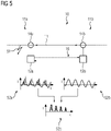
- Figur 5
- ein Differentialschutzsystem im Fall einer durch Wandlersättigung gestörten Messung bei einem äußeren Fehler mit Kompensation durch Verwendung eines Ladungs-Schätzwertes; und
- Figur 6
- ein Differentialschutzsystem im Fall einer durch Wandlersättigung gestörten Messung bei einem inneren Fehler mit Kompensation durch Verwendung eines Ladungs-Schätzwertes.
- figure 1
- a differential protection system in the event of a measurement disturbed by transformer saturation in the event of an external fault;
- figure 2
- a differential protection system in the event of a measurement disturbed by transformer saturation in the event of an internal fault;
- figure 3
- a first example of the formation of a charge estimate;
- figure 4
- a second example of forming a charge estimate;
- figure 5
- a differential protection system in case of a measurement disturbed by transducer saturation at an external fault with compensation by using a charge estimate; and
- figure 6
- a differential protection system in the event of a measurement disturbed by transformer saturation in the event of an internal fault, with compensation using a charge estimate.
Aus den Strommesswerten kann in der Auswerteeinrichtung der jeweiligen Differentialschutzeinrichtung 12a, 12b durch zeitliche Integration oder Summation der Strommesswerte über ein vorgegebenes Zeitintervall, z.B. ¼ Periode oder ½ Periode der Netzfrequenz, ein jeweiliger Ladungswert gebildet werden, der phasenweise die während des Zeitintervalls an dem jeweiligen Leitungsende geflossene Ladungsmenge angibt.From the measured current values, a respective charge value can be formed in the evaluation device of the respective
Die Differentialschutzeinrichtungen 12a bzw. 12b sind durch eine in
Anhand der in beiden Differentialschutzeinrichtungen 12a und 12b verfügbaren Ladungswerte von beiden Enden 11a und 11b der Leitung 11 kann in einer oder beiden Differentialschutzeinrichtungen 12a bzw. 12b mittels der Auswerteeinrichtung durch vorzeichenrichtige Addition der Ladungswerte und anschließende Betragsbildung pro Phase ein Summenladungswert gebildet und mit einem Ladungs-Schwellenwert verglichen werden.On the basis of the charge values from both
Bei fehlerfreier Leitung 11 ist die pro Phase in die Leitung 11 eintretende Ladungsmenge gleich der aus der Leitung 11 austretenden Ladungsmenge, so dass sich bei vorzeichenrichtiger Addition der Ladungswerte ein Wert mit dem Betrag von etwa Null ergeben müsste.If the
Überschreitet für eine bestimmte Phase der Summenladungswert den vorgegebenen Ladungs-Schwellenwert, so weist dies auf einen inneren Fehler hinsichtlich der betreffenden Phase der Leitung 11 hin, bei dem es sich beispielsweise um einen Kurzschluss mit Erdbeteiligung oder einen zwei- oder mehrpoligen Kurzschluss, d.h. einen Kurzschluss zwischen zwei oder mehr Phasen der Leitung 11, handeln kann. Für diejenige Phase, bei der der Fehler erkannt worden ist, erzeugen die Differentialschutzeinrichtungen 12a und 12b ein Fehlersignal, wodurch die Abgabe eines Auslösesignals über Steuerleitungen an in der
Für den Fall, dass mindestens einer der Stromwandler 14a, 14b in einen Sättigungszustand fällt, kann das Stromsignal jedoch nicht mehr korrekt aus dem primärseitig auftretenden Strom erzeugt werden, so dass bei der Ermittlung des entsprechenden Ladungswertes ein signifikanter Fehler auftritt.In the event that at least one of the
In
In Diagramm 15b ist der Verlauf des sekundärseitig vom Stromwandler 14b abgegebenen Stromsignals gezeigt. Dieser Stromwandler 14b ist nicht durch Wandlersättigung beeinträchtigt, so dass der erzeugte Stromverlauf den primärseitig anliegenden Strom korrekt wiedergibt.Diagram 15b shows the progression of the current signal emitted on the secondary side by
In Diagramm 15c ist zur Veranschaulichung des Fehlers, der durch die verfälschte Messung des Stromwandlers 14a entsteht, der Verlauf der Differenz der beiden Stromverläufe dargestellt. Für den hier vorliegenden Fall eines äußeren Fehlers erkennt man, dass ein signifikanter Differenzstrom auftritt. In entsprechender Weise ist durch die verfälschte Messung des Stromwandlers 14a der aus den Strommesswerten erzeugte Ladungswert fehlerbehaftet, so dass bei einem Vergleich der Ladungssumme mit dem Ladungs-Schwellenwert ein innerer Fehler erkannt wird. Dadurch wird eine ungewollte Abschaltung der Leitung verursacht.In diagram 15c, the course of the difference between the two current courses is shown to illustrate the error that arises from the erroneous measurement of the
Um dennoch auch bei vorliegender Wandlersättigung eine zuverlässige Entscheidung über das Vorliegen innerer oder äußerer Fehler treffen zu können, wird bei der Bildung des Ladungswertes die durch Wandlersättigung eintretende Verfälschung des Stromsignals durch Bildung von Ladungs-Schätzwerten kompensiert.In order to be able to make a reliable decision about the presence of internal or external faults even when the converter is saturated, the falsification of the current signal caused by converter saturation is compensated for by the formation of estimated charge values when the charge value is formed.
Ein Ausführungsbeispiel zur Bildung eines Ladungs-Schätzwertes ist in
Daher wird die geflossene Ladungsmenge mittels eines Ladungs-Schätzwertes abgeschätzt. Im Fall der ![]()

![]()
Anschaulich gesprochen wird der Wert der innerhalb des Zeitintervalls Tend-Tstart geflossenen Ladungsmenge somit als die Summe der beiden Flächenanteile 33 und 34 bestimmt. Man erkennt, dass durch die Verwendung der Geraden der Ladungs-Schätzwert relativ gut an diejenige Ladungsmenge angepasst werden kann, die ohne Wandlersättigung bestimmt worden wäre.Clearly speaking, the value of the amount of charge that has flowed within the time interval T end -T start is thus determined as the sum of the two
Diese Vorgehensweise der Bildung eines Ladungs-Schätzwertes eignet sich insbesondere in Fällen, in denen die Wandlersättigung bereits recht früh nach dem Nulldurchgang des Stromverlaufs eintritt.This procedure for forming an estimated charge value is particularly suitable in cases in which the converter saturation occurs quite early after the zero crossing of the current curve.
Eine Alternative zur Bestimmung eines Ladungs-Schätzwertes ist in
Da durch die Bildung des Ladungs-Schätzwertes in die Bildung der Ladungssumme jeweils Werte eingehen, die zwar dem tatsächlichen Wert angenähert sind, diesen aber nicht vollständig korrekt annehmen, ist vorteilhaft in Fällen erkannter Wandlersättigung einen zeitweise erhöhten Ladungs-Schwellenwert für die Entscheidung über das Vorliegen eines inneren Fehlers zu verwenden.Since the formation of the estimated charge value means that values are included in the formation of the charge sum that approximate the actual value, but not completely assume correctly, it is advantageous in cases where converter saturation is detected to use a temporarily increased charge threshold value to decide whether an internal fault is present.
In
In
Der verwendete Ladungs-Schwellenwert kann als separater Parameter oder als Kennlinie in einem Auslösediagramm festgelegt sein.The charge threshold used can be specified as a separate parameter or as a characteristic in a trip diagram.
Obwohl gemäß den
Außerdem kann in Abweichung zur Darstellung gemäß
Bei dem beschriebenen Differentialschutzverfahren wird somit quasi eine verlorene Information über den Verlauf des Stromsignals nach Eintritt der Stromwandlersättigung auf sehr einfache Art und Weise zurückgewonnen, so dass Maßnahmen zur übermäßigen Stabilisierung gegen Messfehler bis hin zur Blockierung der Messung vermieden werden können.With the differential protection method described, lost information about the course of the current signal after the current transformer saturation has occurred is recovered in a very simple manner, so that measures for excessive stabilization against measurement errors up to and including blocking of the measurement can be avoided.
Das beschriebene Verfahren benutzt mit anderen Worten das zeitliche Stromintegral anstatt die Momentanwerte oder Zeiger der Ströme. Erfindungsgemäß wird das zeitliche Stromintegral nicht durch die Rekonstruktion der einzelnen Momentanwerte, sondern durch eine gleichwertige Äquivalenzfläche gewonnen. Da diese Äquivalenzfläche, bedingt durch ihre Einfachheit fehlerbehaftet ist, wird sie mit einem entsprechend höheren Stabilisierungsbeitrag bewertet.In other words, the method described uses the time integral of the current instead of the instantaneous values or vectors of the currents. According to the invention, the current integral over time is not obtained through the reconstruction of the individual instantaneous values, but through an equivalent equivalent area. Since this equivalent surface is subject to errors due to its simplicity, it is evaluated with a correspondingly higher stabilization contribution.
Obwohl die Erfindung vorstehend im Detail durch bevorzugte Ausführungsbeispiele näher illustriert und beschrieben worden ist, ist die Erfindung nicht durch die offenbarten Beispiele eingeschränkt und andere Variationen können vom Fachmann hieraus abgeleitet werden, ohne den Schutzumfang der nachfolgenden Patentansprüche zu verlassen.Although the invention has been illustrated and described in detail above by means of preferred exemplary embodiments, the invention is not limited by the disclosed examples and other variations can be derived therefrom by a person skilled in the art without departing from the protective scope of the following claims.
Claims (9)
- Differential protection method for monitoring a line (11) of an electrical energy supply network, in which method- current signals are generated at the ends (11a, 11b) of the line (11) using inductive current transformers (14a, 14b), which current signals are proportional to a current flowing at the respective end (11a, 11b);- for each end (11a, 11b), current measurement values are formed from the respective current signal using measuring devices, which current measurement values indicate a profile of the current flowing at the respective end (11a, 11b);- for each end, a respective charge value is determined from the current measurement values;- the charge values of all the ends (11a, 11b) are summed with the correct mathematical sign so as to form a charge sum; and- a fault signal that indicates an internal fault on the line (11) is generated when the charge sum exceeds a charge threshold value;characterized in that- an estimated charge value is determined using the corresponding measuring device when transformer saturation of a current transformer is present; and- the estimated charge value is used, instead of the charge value distorted by transformer saturation, to form the charge sum.
- Method according to Claim 1,
characterized in that- a temporal integral over the current measurement values of the respective end (11a, 11b) of the line (11) is formed during a prescribed time interval to form the respective charge value. - Method according to Claim 2,
characterized in that- the estimated charge value is determined using at least one current measurement value present at the onset time of the transformer saturation. - Method according to Claim 3,
characterized in that- a straight line (35) that passes on the one hand through the current measurement value at the onset time of the transformer saturation and on the other hand through the last zero crossing of the current profile is determined to ascertain the estimated charge value; and- the estimated charge value is determined as the area lying within the time interval between the straight line (35) and the zero line. - Method according to Claim 3,
characterized in that- a rectangle (45) is formed to ascertain the estimated charge value, one side of which rectangle is determined by the current measurement value at the onset time of the transformer saturation and the other side of which rectangle is determined by the duration of the time interval; and- the estimated charge value is determined as the area of the rectangle (45). - Method according to one of Claims 3 to 5,
characterized in that- a difference value between a present current measurement value and a predicted value is determined to identify the onset time of the transformer saturation, wherein the predicted value indicates an expected profile of the current; and- the onset time is identified when the difference value exceeds a saturation threshold value. - Method according to one of the preceding claims,- the charge threshold value is temporarily increased when transformer saturation is present.
- Differential protective device (12a) for monitoring a line (11) of an electrical energy supply network, said differential protective device having- a measuring device which is configured to detect a current signal generated at an end (11a) of the line (11) and to form current measurement values which indicate a profile of a current flowing at the respective end (11a), wherein the current signal has been produced proportionally to a current flowing at the end using an inductive current transformer (14a); and- an evaluation device which is configured to determine a charge value from the current measurement values, to sum the charge values with a charge measurement value of at least one other differential protective device (12b) with the correct mathematical sign so as to form a charge sum and to generate a fault signal that indicates an internal fault on the line (11) when the charge sum exceeds a charge threshold value;characterized in that- the evaluation device is configured, when transformer saturation of the current transformer (14a) is present, to ascertain an estimated charge value and to use said estimated charge value, instead of the charge value distorted by transformer saturation, to form the charge sum.
- Differential protective system for monitoring a line (11) of an electrical energy supply network, wherein the line (11) has at least two ends (11a, 11b), and wherein a differential protective device according to Claim 8 is arranged at each end (11a, 11b).
Priority Applications (3)
| Application Number | Priority Date | Filing Date | Title |
|---|---|---|---|
| EP17187273.2A EP3447870B1 (en) | 2017-08-22 | 2017-08-22 | Differential protection method, differential protection device and differential protection system |
| BR102018016393-0A BR102018016393B1 (en) | 2017-08-22 | 2018-08-10 | DIFFERENTIAL PROTECTION METHOD, DIFFERENTIAL PROTECTIVE DEVICE AND DIFFERENTIAL PROTECTIVE SYSTEM |
| US16/106,333 US10862291B2 (en) | 2017-08-22 | 2018-08-21 | Differential protection method, device and system for monitoring a line of an electrical energy supply network |
Applications Claiming Priority (1)
| Application Number | Priority Date | Filing Date | Title |
|---|---|---|---|
| EP17187273.2A EP3447870B1 (en) | 2017-08-22 | 2017-08-22 | Differential protection method, differential protection device and differential protection system |
Publications (2)
| Publication Number | Publication Date |
|---|---|
| EP3447870A1 EP3447870A1 (en) | 2019-02-27 |
| EP3447870B1 true EP3447870B1 (en) | 2022-11-30 |
Family
ID=59686797
Family Applications (1)
| Application Number | Title | Priority Date | Filing Date |
|---|---|---|---|
| EP17187273.2A Active EP3447870B1 (en) | 2017-08-22 | 2017-08-22 | Differential protection method, differential protection device and differential protection system |
Country Status (2)
| Country | Link |
|---|---|
| US (1) | US10862291B2 (en) |
| EP (1) | EP3447870B1 (en) |
Families Citing this family (8)
| Publication number | Priority date | Publication date | Assignee | Title |
|---|---|---|---|---|
| CN109768526B (en) * | 2019-03-13 | 2020-09-04 | 南京南瑞继保电气有限公司 | Method and device for identifying non-fault phase saturation based on current distribution coefficient |
| CN111030051B (en) * | 2019-11-26 | 2021-10-08 | 国网江苏省电力有限公司检修分公司 | Differential protection method |
| CN112072621B (en) * | 2020-09-10 | 2023-03-31 | 合肥工业大学 | Differential protection method for power distribution network line based on 5G communication and dynamic mode matching |
| CN113917261B (en) * | 2021-09-30 | 2023-08-04 | 广东电网有限责任公司 | Differential protection parameter verification method and device for direct current protection equipment |
| CN113970686B (en) * | 2021-10-27 | 2022-08-30 | 西南交通大学 | Power distribution network fault detection method and system based on single-ended quantity protection and positioning method |
| CN113970685B (en) * | 2021-10-27 | 2022-08-30 | 西南交通大学 | Power distribution network fault detection method and system based on differential analysis and positioning method |
| CN114123135B (en) * | 2021-11-29 | 2024-04-26 | 南京智汇电力技术有限公司 | Power distribution network differential synchronization method under wireless communication |
| CN115792782B (en) * | 2023-01-06 | 2023-04-14 | 石家庄科林电气股份有限公司 | CT saturation recognition method and device, electronic equipment and storage medium |
Family Cites Families (13)
| Publication number | Priority date | Publication date | Assignee | Title |
|---|---|---|---|---|
| US4280093A (en) * | 1979-08-27 | 1981-07-21 | General Electric Company | Zero-current detector for high voltage DC transmission line |
| DE4420513A1 (en) * | 1994-06-13 | 1995-12-14 | Abb Management Ag | Protecting bus=bars using constant k with value greater than k equal to 2 outputs |
| JPH10221382A (en) * | 1997-01-24 | 1998-08-21 | Eaton Corp | Measuring device of ac current and method therefor |
| US6043641A (en) * | 1998-02-17 | 2000-03-28 | Singer; Jerome R. | Method and apparatus for rapid determinations of voltage and current in wires and conductors |
| US6392401B1 (en) * | 1998-06-05 | 2002-05-21 | Chathan M. Cooke | Closely-coupled multiple-winding magnetic induction-type sensor |
| DE19928192B4 (en) * | 1999-06-19 | 2005-08-25 | Abb Patent Gmbh | Process for the reconstruction of a stream |
| DE19959776B4 (en) | 1999-12-07 | 2008-12-11 | Siemens Ag | Differential protection method |
| US6501631B1 (en) * | 2000-04-14 | 2002-12-31 | Abb Ab | Method and device for power system protection |
| JP4555090B2 (en) | 2003-04-17 | 2010-09-29 | ハンコック アイイーディー | Secondary current compensation method for current transformer |
| US7636396B1 (en) * | 2004-04-26 | 2009-12-22 | Dgi Creations, Llc | Method of testing remote power line carrier pick-up coil |
| PL382552A1 (en) | 2007-05-31 | 2008-12-08 | Siemens Aktiengesellschaft | The manner of correction of the course of secondary current interrupted by saturation of current measuring transformer and electric device for execution of this process |
| US7738221B2 (en) * | 2007-12-07 | 2010-06-15 | Cooper Technologies Company | Transformer inrush current detector |
| US9891289B2 (en) * | 2014-06-03 | 2018-02-13 | Cooper Technologies Company | Power transformer inrush current detector |
-
2017
- 2017-08-22 EP EP17187273.2A patent/EP3447870B1/en active Active
-
2018
- 2018-08-21 US US16/106,333 patent/US10862291B2/en active Active
Also Published As
| Publication number | Publication date |
|---|---|
| US10862291B2 (en) | 2020-12-08 |
| US20190067928A1 (en) | 2019-02-28 |
| EP3447870A1 (en) | 2019-02-27 |
| BR102018016393A2 (en) | 2019-03-19 |
Similar Documents
| Publication | Publication Date | Title |
|---|---|---|
| EP3447870B1 (en) | Differential protection method, differential protection device and differential protection system | |
| EP3198698B1 (en) | Differential protection method and differential protection device for performing a differential protection method | |
| DE102004056436B4 (en) | Method and device for detecting residual current arcs in electrical circuits | |
| EP2605354B1 (en) | Protection for parallel lines in an electrical energy supply network | |
| EP3136528B1 (en) | Differential protection method, differential protection device and differential protection system | |
| WO2008034400A1 (en) | Method for producing a fault signal, which indicates a fault present in a secondary current transformer circuit, and differential protective device | |
| WO2015028062A1 (en) | Differential protection method and differential protection device for performing a differential protection method | |
| EP3300199B1 (en) | Method and device of controlling a circuit breaker for an electrical energy supply system at current zero crossing | |
| DE102007017543B4 (en) | Method for the distance detection of earth faults | |
| EP3876373B1 (en) | Differential protection method, differential protection device and differential protection system | |
| EP1416287B1 (en) | Method of generating an error signal indicating a short-circuit to the earth | |
| DE2604311A1 (en) | PHASE COMPARISON RELAY | |
| EP3108554B1 (en) | Differential protection method and differential protection device | |
| EP3207610B1 (en) | Method and protection device for generating an error signal indicating an error type of an error in a multi-phase electrical energy supply network | |
| EP2345123B1 (en) | Differential protection method and differential protection device | |
| WO2013060382A1 (en) | Method and protective device for identifying a ground fault in a polyphase electrical energy supply network having a compensated or isolated star point | |
| EP3595114B1 (en) | Method and arrangement for detecting a winding defect in a transformer on the basis of corresponding negative sequence current values | |
| EP2901534B1 (en) | Differential protection method and protective device for carrying out a differential protection method | |
| EP1478070B1 (en) | All fault-current sensitive protection device | |
| DE4026799A1 (en) | Selective detection of faults in conductors in high voltage network - by comparing conductor voltages and currents with earth current and star earth voltage | |
| AT503598A2 (en) | Earth fault distance locating method for earth fault-compensated, operated three-phase-electrical power network, involves calculating distance to earth fault based on phase voltage under consideration of earth impedance | |
| DE10237342B4 (en) | Method and device for monitoring residual current in an electrical AC network | |
| EP3913382B1 (en) | Method and device for determining the location of a three-pole assymetrical fault on a line of a three-phase electrical energy supply network | |
| EP4152539B1 (en) | Arrangement and method for a low voltage alternating current circuit | |
| DE19920654A1 (en) | Determining conductor impedance threshold involves automatically deriving threshold value from predefined threshold value depending on determined degree of dependability of current value |
Legal Events
| Date | Code | Title | Description |
|---|---|---|---|
| PUAI | Public reference made under article 153(3) epc to a published international application that has entered the european phase |
Free format text: ORIGINAL CODE: 0009012 |
|
| STAA | Information on the status of an ep patent application or granted ep patent |
Free format text: STATUS: THE APPLICATION HAS BEEN PUBLISHED |
|
| AK | Designated contracting states |
Kind code of ref document: A1 Designated state(s): AL AT BE BG CH CY CZ DE DK EE ES FI FR GB GR HR HU IE IS IT LI LT LU LV MC MK MT NL NO PL PT RO RS SE SI SK SM TR |
|
| AX | Request for extension of the european patent |
Extension state: BA ME |
|
| STAA | Information on the status of an ep patent application or granted ep patent |
Free format text: STATUS: REQUEST FOR EXAMINATION WAS MADE |
|
| 17P | Request for examination filed |
Effective date: 20190719 |
|
| RBV | Designated contracting states (corrected) |
Designated state(s): AL AT BE BG CH CY CZ DE DK EE ES FI FR GB GR HR HU IE IS IT LI LT LU LV MC MK MT NL NO PL PT RO RS SE SI SK SM TR |
|
| STAA | Information on the status of an ep patent application or granted ep patent |
Free format text: STATUS: EXAMINATION IS IN PROGRESS |
|
| STAA | Information on the status of an ep patent application or granted ep patent |
Free format text: STATUS: EXAMINATION IS IN PROGRESS |
|
| 17Q | First examination report despatched |
Effective date: 20211001 |
|
| GRAP | Despatch of communication of intention to grant a patent |
Free format text: ORIGINAL CODE: EPIDOSNIGR1 |
|
| RIC1 | Information provided on ipc code assigned before grant |
Ipc: G01R 15/18 20060101ALN20220615BHEP Ipc: G01R 19/10 20060101ALN20220615BHEP Ipc: H02H 3/28 20060101ALI20220615BHEP Ipc: H02H 1/04 20060101AFI20220615BHEP |
|
| STAA | Information on the status of an ep patent application or granted ep patent |
Free format text: STATUS: GRANT OF PATENT IS INTENDED |
|
| INTG | Intention to grant announced |
Effective date: 20220721 |
|
| GRAS | Grant fee paid |
Free format text: ORIGINAL CODE: EPIDOSNIGR3 |
|
| GRAA | (expected) grant |
Free format text: ORIGINAL CODE: 0009210 |
|
| STAA | Information on the status of an ep patent application or granted ep patent |
Free format text: STATUS: THE PATENT HAS BEEN GRANTED |
|
| AK | Designated contracting states |
Kind code of ref document: B1 Designated state(s): AL AT BE BG CH CY CZ DE DK EE ES FI FR GB GR HR HU IE IS IT LI LT LU LV MC MK MT NL NO PL PT RO RS SE SI SK SM TR |
|
| REG | Reference to a national code |
Ref country code: CH Ref legal event code: EP Ref country code: GB Ref legal event code: FG4D Free format text: NOT ENGLISH |
|
| REG | Reference to a national code |
Ref country code: AT Ref legal event code: REF Ref document number: 1535421 Country of ref document: AT Kind code of ref document: T Effective date: 20221215 Ref country code: DE Ref legal event code: R096 Ref document number: 502017014141 Country of ref document: DE |
|
| REG | Reference to a national code |
Ref country code: IE Ref legal event code: FG4D Free format text: LANGUAGE OF EP DOCUMENT: GERMAN |
|
| REG | Reference to a national code |
Ref country code: LT Ref legal event code: MG9D |
|
| REG | Reference to a national code |
Ref country code: NL Ref legal event code: MP Effective date: 20221130 |
|
| PG25 | Lapsed in a contracting state [announced via postgrant information from national office to epo] |
Ref country code: SE Free format text: LAPSE BECAUSE OF FAILURE TO SUBMIT A TRANSLATION OF THE DESCRIPTION OR TO PAY THE FEE WITHIN THE PRESCRIBED TIME-LIMIT Effective date: 20221130 Ref country code: PT Free format text: LAPSE BECAUSE OF FAILURE TO SUBMIT A TRANSLATION OF THE DESCRIPTION OR TO PAY THE FEE WITHIN THE PRESCRIBED TIME-LIMIT Effective date: 20230331 Ref country code: NO Free format text: LAPSE BECAUSE OF FAILURE TO SUBMIT A TRANSLATION OF THE DESCRIPTION OR TO PAY THE FEE WITHIN THE PRESCRIBED TIME-LIMIT Effective date: 20230228 Ref country code: LT Free format text: LAPSE BECAUSE OF FAILURE TO SUBMIT A TRANSLATION OF THE DESCRIPTION OR TO PAY THE FEE WITHIN THE PRESCRIBED TIME-LIMIT Effective date: 20221130 Ref country code: FI Free format text: LAPSE BECAUSE OF FAILURE TO SUBMIT A TRANSLATION OF THE DESCRIPTION OR TO PAY THE FEE WITHIN THE PRESCRIBED TIME-LIMIT Effective date: 20221130 Ref country code: ES Free format text: LAPSE BECAUSE OF FAILURE TO SUBMIT A TRANSLATION OF THE DESCRIPTION OR TO PAY THE FEE WITHIN THE PRESCRIBED TIME-LIMIT Effective date: 20221130 |
|
| PG25 | Lapsed in a contracting state [announced via postgrant information from national office to epo] |
Ref country code: RS Free format text: LAPSE BECAUSE OF FAILURE TO SUBMIT A TRANSLATION OF THE DESCRIPTION OR TO PAY THE FEE WITHIN THE PRESCRIBED TIME-LIMIT Effective date: 20221130 Ref country code: PL Free format text: LAPSE BECAUSE OF FAILURE TO SUBMIT A TRANSLATION OF THE DESCRIPTION OR TO PAY THE FEE WITHIN THE PRESCRIBED TIME-LIMIT Effective date: 20221130 Ref country code: LV Free format text: LAPSE BECAUSE OF FAILURE TO SUBMIT A TRANSLATION OF THE DESCRIPTION OR TO PAY THE FEE WITHIN THE PRESCRIBED TIME-LIMIT Effective date: 20221130 Ref country code: IS Free format text: LAPSE BECAUSE OF FAILURE TO SUBMIT A TRANSLATION OF THE DESCRIPTION OR TO PAY THE FEE WITHIN THE PRESCRIBED TIME-LIMIT Effective date: 20230330 Ref country code: HR Free format text: LAPSE BECAUSE OF FAILURE TO SUBMIT A TRANSLATION OF THE DESCRIPTION OR TO PAY THE FEE WITHIN THE PRESCRIBED TIME-LIMIT Effective date: 20221130 Ref country code: GR Free format text: LAPSE BECAUSE OF FAILURE TO SUBMIT A TRANSLATION OF THE DESCRIPTION OR TO PAY THE FEE WITHIN THE PRESCRIBED TIME-LIMIT Effective date: 20230301 |
|
| PG25 | Lapsed in a contracting state [announced via postgrant information from national office to epo] |
Ref country code: NL Free format text: LAPSE BECAUSE OF FAILURE TO SUBMIT A TRANSLATION OF THE DESCRIPTION OR TO PAY THE FEE WITHIN THE PRESCRIBED TIME-LIMIT Effective date: 20221130 |
|
| PG25 | Lapsed in a contracting state [announced via postgrant information from national office to epo] |
Ref country code: SM Free format text: LAPSE BECAUSE OF FAILURE TO SUBMIT A TRANSLATION OF THE DESCRIPTION OR TO PAY THE FEE WITHIN THE PRESCRIBED TIME-LIMIT Effective date: 20221130 Ref country code: RO Free format text: LAPSE BECAUSE OF FAILURE TO SUBMIT A TRANSLATION OF THE DESCRIPTION OR TO PAY THE FEE WITHIN THE PRESCRIBED TIME-LIMIT Effective date: 20221130 Ref country code: EE Free format text: LAPSE BECAUSE OF FAILURE TO SUBMIT A TRANSLATION OF THE DESCRIPTION OR TO PAY THE FEE WITHIN THE PRESCRIBED TIME-LIMIT Effective date: 20221130 Ref country code: DK Free format text: LAPSE BECAUSE OF FAILURE TO SUBMIT A TRANSLATION OF THE DESCRIPTION OR TO PAY THE FEE WITHIN THE PRESCRIBED TIME-LIMIT Effective date: 20221130 Ref country code: CZ Free format text: LAPSE BECAUSE OF FAILURE TO SUBMIT A TRANSLATION OF THE DESCRIPTION OR TO PAY THE FEE WITHIN THE PRESCRIBED TIME-LIMIT Effective date: 20221130 |
|
| PG25 | Lapsed in a contracting state [announced via postgrant information from national office to epo] |
Ref country code: SK Free format text: LAPSE BECAUSE OF FAILURE TO SUBMIT A TRANSLATION OF THE DESCRIPTION OR TO PAY THE FEE WITHIN THE PRESCRIBED TIME-LIMIT Effective date: 20221130 Ref country code: AL Free format text: LAPSE BECAUSE OF FAILURE TO SUBMIT A TRANSLATION OF THE DESCRIPTION OR TO PAY THE FEE WITHIN THE PRESCRIBED TIME-LIMIT Effective date: 20221130 |
|
| REG | Reference to a national code |
Ref country code: DE Ref legal event code: R097 Ref document number: 502017014141 Country of ref document: DE |
|
| PLBE | No opposition filed within time limit |
Free format text: ORIGINAL CODE: 0009261 |
|
| STAA | Information on the status of an ep patent application or granted ep patent |
Free format text: STATUS: NO OPPOSITION FILED WITHIN TIME LIMIT |
|
| PGFP | Annual fee paid to national office [announced via postgrant information from national office to epo] |
Ref country code: IT Payment date: 20230828 Year of fee payment: 7 Ref country code: GB Payment date: 20230904 Year of fee payment: 7 |
|
| 26N | No opposition filed |
Effective date: 20230831 |
|
| PG25 | Lapsed in a contracting state [announced via postgrant information from national office to epo] |
Ref country code: SI Free format text: LAPSE BECAUSE OF FAILURE TO SUBMIT A TRANSLATION OF THE DESCRIPTION OR TO PAY THE FEE WITHIN THE PRESCRIBED TIME-LIMIT Effective date: 20221130 |
|
| PGFP | Annual fee paid to national office [announced via postgrant information from national office to epo] |
Ref country code: FR Payment date: 20230822 Year of fee payment: 7 |
|
| PGFP | Annual fee paid to national office [announced via postgrant information from national office to epo] |
Ref country code: DE Payment date: 20231019 Year of fee payment: 7 |
|
| PG25 | Lapsed in a contracting state [announced via postgrant information from national office to epo] |
Ref country code: MC Free format text: LAPSE BECAUSE OF FAILURE TO SUBMIT A TRANSLATION OF THE DESCRIPTION OR TO PAY THE FEE WITHIN THE PRESCRIBED TIME-LIMIT Effective date: 20221130 |
|
| REG | Reference to a national code |
Ref country code: CH Ref legal event code: PL |
|
| PG25 | Lapsed in a contracting state [announced via postgrant information from national office to epo] |
Ref country code: MC Free format text: LAPSE BECAUSE OF FAILURE TO SUBMIT A TRANSLATION OF THE DESCRIPTION OR TO PAY THE FEE WITHIN THE PRESCRIBED TIME-LIMIT Effective date: 20221130 |
|
| PG25 | Lapsed in a contracting state [announced via postgrant information from national office to epo] |
Ref country code: LU Free format text: LAPSE BECAUSE OF NON-PAYMENT OF DUE FEES Effective date: 20230822 |
|
| PG25 | Lapsed in a contracting state [announced via postgrant information from national office to epo] |
Ref country code: LU Free format text: LAPSE BECAUSE OF NON-PAYMENT OF DUE FEES Effective date: 20230822 Ref country code: CH Free format text: LAPSE BECAUSE OF NON-PAYMENT OF DUE FEES Effective date: 20230831 |