EP3441204B1 - Loading device and method tool using the same - Google Patents
Loading device and method tool using the same Download PDFInfo
- Publication number
- EP3441204B1 EP3441204B1 EP18179208.6A EP18179208A EP3441204B1 EP 3441204 B1 EP3441204 B1 EP 3441204B1 EP 18179208 A EP18179208 A EP 18179208A EP 3441204 B1 EP3441204 B1 EP 3441204B1
- Authority
- EP
- European Patent Office
- Prior art keywords
- chuck
- workpiece
- closed
- end position
- sensor
- Prior art date
- Legal status (The legal status is an assumption and is not a legal conclusion. Google has not performed a legal analysis and makes no representation as to the accuracy of the status listed.)
- Active
Links
- 238000000034 method Methods 0.000 title description 5
- 230000007246 mechanism Effects 0.000 claims description 15
- 238000005259 measurement Methods 0.000 claims description 5
- 238000010586 diagram Methods 0.000 description 13
- 241000282472 Canis lupus familiaris Species 0.000 description 12
- 238000012545 processing Methods 0.000 description 6
- 230000009471 action Effects 0.000 description 4
- 230000008859 change Effects 0.000 description 4
- 230000008569 process Effects 0.000 description 4
- 230000005856 abnormality Effects 0.000 description 3
- 230000001419 dependent effect Effects 0.000 description 2
- 230000009467 reduction Effects 0.000 description 2
- 230000002159 abnormal effect Effects 0.000 description 1
- 238000004891 communication Methods 0.000 description 1
- 238000001514 detection method Methods 0.000 description 1
- 230000007257 malfunction Effects 0.000 description 1
- 238000012986 modification Methods 0.000 description 1
- 230000004048 modification Effects 0.000 description 1
- 230000002123 temporal effect Effects 0.000 description 1
- 210000000707 wrist Anatomy 0.000 description 1
Images

Classifications
-
- B—PERFORMING OPERATIONS; TRANSPORTING
- B25—HAND TOOLS; PORTABLE POWER-DRIVEN TOOLS; MANIPULATORS
- B25J—MANIPULATORS; CHAMBERS PROVIDED WITH MANIPULATION DEVICES
- B25J13/00—Controls for manipulators
- B25J13/08—Controls for manipulators by means of sensing devices, e.g. viewing or touching devices
-
- B—PERFORMING OPERATIONS; TRANSPORTING
- B23—MACHINE TOOLS; METAL-WORKING NOT OTHERWISE PROVIDED FOR
- B23Q—DETAILS, COMPONENTS, OR ACCESSORIES FOR MACHINE TOOLS, e.g. ARRANGEMENTS FOR COPYING OR CONTROLLING; MACHINE TOOLS IN GENERAL CHARACTERISED BY THE CONSTRUCTION OF PARTICULAR DETAILS OR COMPONENTS; COMBINATIONS OR ASSOCIATIONS OF METAL-WORKING MACHINES, NOT DIRECTED TO A PARTICULAR RESULT
- B23Q17/00—Arrangements for observing, indicating or measuring on machine tools
- B23Q17/002—Arrangements for observing, indicating or measuring on machine tools for indicating or measuring the holding action of work or tool holders
- B23Q17/003—Arrangements for observing, indicating or measuring on machine tools for indicating or measuring the holding action of work or tool holders by measuring a position
-
- B—PERFORMING OPERATIONS; TRANSPORTING
- B23—MACHINE TOOLS; METAL-WORKING NOT OTHERWISE PROVIDED FOR
- B23Q—DETAILS, COMPONENTS, OR ACCESSORIES FOR MACHINE TOOLS, e.g. ARRANGEMENTS FOR COPYING OR CONTROLLING; MACHINE TOOLS IN GENERAL CHARACTERISED BY THE CONSTRUCTION OF PARTICULAR DETAILS OR COMPONENTS; COMBINATIONS OR ASSOCIATIONS OF METAL-WORKING MACHINES, NOT DIRECTED TO A PARTICULAR RESULT
- B23Q7/00—Arrangements for handling work specially combined with or arranged in, or specially adapted for use in connection with, machine tools, e.g. for conveying, loading, positioning, discharging, sorting
- B23Q7/04—Arrangements for handling work specially combined with or arranged in, or specially adapted for use in connection with, machine tools, e.g. for conveying, loading, positioning, discharging, sorting by means of grippers
-
- B—PERFORMING OPERATIONS; TRANSPORTING
- B23—MACHINE TOOLS; METAL-WORKING NOT OTHERWISE PROVIDED FOR
- B23B—TURNING; BORING
- B23B2260/00—Details of constructional elements
- B23B2260/128—Sensors
Definitions
- the present invention relates to a machine tool using a loading device for delivery of a workpiece to and from the spindle of the machine tool according to claim 1.
- Machine tools such as lathes and complex processing machines have a chuck for gripping a workpiece at the leading end of a rotationally driven spindle.
- Loading devices delivering a workpiece to and from the spindle also have a chuck for gripping the workpiece.
- These chucks have dogs as detected sections for detecting the open end and closed end of chuck jaws. After the chuck of the spindle completely grips a workpiece, the chuck jaws of the chuck provided in the loading device are opened. The open end of the chuck jaws is detected by detecting the dogs, and then the chuck in the loading device is moved.
- JP-A-2005-186191 describes that five proximity switches are provided at specific intervals along the stroke direction of a piston rod in a cylinder opening and closing chuck jaws on a spindle to detect dogs at the rear end of the piston rod. This makes it possible to detect dogs located at positions other than the both stroke ends of the piston rod.
- the document DE 296 02 216 U1 discloses a gripping device with a housing, in which a central receiving hole and a lateral longitudinal recess are provided.
- sensors can be arranged for detecting end positions of a gripping unit being provided in the receiving hole.
- sensors hall sensors or mechanical switches can be used.
- the gripping device comprises jaws being moveable by linearly movable pistons, one of which includes a magnet to be detected by a sensor arrangement.
- the rod-like sensor arrangement comprises two end sensors and one intermediate sensor for detecting end positions and one intermediate position.
- a machine tool with a control unit is disclosed in US 6,705,186 B2 .
- DE 3 813 708 A1 discloses robotic grippers in which the opening positions of the gripper fingers may be continuously monitored by means of Hall-sensor between a fully opened and a fully closed position of the gripper.
- An operator of the disclosed robot gripper may set different opening positions for the gripper fingers which then may selectively grip differently sized workpieces. If an operator would set two positions corresponding to a gripping and a releasing position of a workpiece, he would not find any hint to start a movement mechanism, such as the wrist or an arm of a robot, dependent on a position lying between the set two positions associated to the selected workpiece.
- DE 10 2015 012 779 A1 shows a comparable robotic gripper in which the fingers are controlled by an electric motor.
- the angular position of the electric motor is sensed by a Hall sensor.
- An object of one aspect of the present invention is to provide a machine tool using a loading device that reduces time loss and shortens the loading time for delivering a workpiece to and from a spindle of the machine tool.
- a loading device comprising a chuck chucking a workpiece on chuck jaws that are opened and closed, and a movement mechanism moving the chuck and delivering the workpiece to and from a spindle of a machine tool
- the sensor here refers to any sensor that can detect a signal continuously changing depending on the positions of open end to closed end of the chuck jaws, which may be of a contact type in contact with the detected section or a non-contact type.
- the sensor is preferably a digital sensor that converts a continuously changing analog signal into a digital signal and outputs the same.
- the principle of detection by the sensor may be to detect a change in a magnetic field or a capacity depending on the positon of the detected section or detect reflection of a laser beam, infrared ray, or ultrasonic wave.
- a single sensor detecting a change in a magnetic field depending on the position of the detected section is compact and inexpensive, and also favorably achieves a positional resolution of 1 mm or less even though the detected section has a relatively short movement range of 10 to 20 mm, for example.
- the movement mechanism can start the movement of the chuck as the next process.
- the chuck in the loading device needs to be held on standby until the opening of the chuck jaws in the loading device is completed. This causes time loss by the standby state of the loading device.
- the loading device before the completion of opening of the chuck jaws in the loading device is detected, the loading device can move to the next process to shorten the time of delivery of a workpiece and improve the efficiency of the loading.
- the present invention relates to a machine tool that has a spindle and a loading device.
- the loading device includes a first chuck and the spindle includes a second chuck.
- a first sensor identical to the sensor described above may be provided in the first chuck and a second sensor identical to the sensor described above may be provided in the second chuck.
- the movement distance of the chuck jaws is acquired based on the output from the sensor and the movement time is acquired from a time measurement section to detect the opening and closing speed of the chuck jaws.
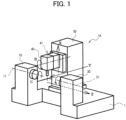
- FIG. 1 illustrates schematically a machine tool to which the present invention is applied.
- FIG. 1 illustrates a double-spindle-opposed turning center 1A in which right and left spindles are laterally opposed to each other.
- FIG. 1 does not illustrate a loading device.
- a workpiece (not shown) is held and rotated by a left spindle 11 and/or a right spindle 31 controlled along a C axis.
- a tool attached to a tool spindle 41 is capable of translational motion along X, Y, and Z axes orthogonal to one another (crossing in a board sense), and is capable of rotational motion around a B axis.
- the spindle 11 is rotatably supported on a headstock 10, and the spindle 31 is rotatably supported on a headstock 30.
- the tool spindle 41 is rotatably supported on a tool post 40.
- a movable carriage 50 is provided in a manner capable of translational motion in the Y- and Z-axis directions with respect to a base 1.
- the tool post 40 is supported movably in the X-axis direction with respect to the movable carriage 50.
- FIG. 2A illustrates an example of a loading device of the machine tool 1A.
- a loading device 20 is included as auxiliary equipment in the machine tool 1A.
- the loading device 20 includes a chuck 20A that chucks a workpiece W, an arm 20B that supports the chuck 20A, and a movement mechanism 60 (not illustrated in FIG.2A but illustrated in FIGs 3 and 5 ) that moves the arm 20B at least in the X-axis direction and the Z-axis direction.
- the L-shaped chuck (also called first chuck) 20A is turnably coupled to the leading end of the arm 20B by a shaft 24.
- the main chuck 21 is switched between an open state in which the workpiece W can be delivered and a closed state in which the workpiece W is gripped, for example, by widening or narrowing three main chuck jaws 21a in a radial direction.
- the sub chuck 22 also has three sub chuck jaws 22a.
- the main chuck jaws 21a include a sensor, for example, a digital sensor 25a that can continuously detect the fully-open state, the fully-closed state, and the intermediate state.
- the sub chuck jaws 22a also include a digital sensor 25b.
- the main chuck jaws 21a and the sub chuck jaws 22a will be collectively called first chuck jaws.
- the digital sensors 25a and 25b will be collectively called first sensor.
- the spindle 11 is provided with a second chuck 12.
- the second chuck 12 has three second chuck jaws 12a that chuck the workpiece W, for example.
- the second chuck jaws 12a can also be provided with a second sensor, for example, a digital sensor 15 that can continuously detect the fully-open state, the fully-closed state, and the intermediate state.
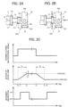
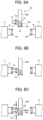
- FIG. 2A illustrates schematically a state in which the workpiece W is delivered from the main chuck 21 of the loading device 20 to the chuck 12 of the spindle 11.
- FIG. 2B illustrates schematically a state in which the main chuck jaws 21a are slightly opened in an arrow direction B under an instruction for opening the main chuck jaws 21a and the chuck 20A in the loading device 20 starts to move in an arrow direction A1 away from the workpiece W.
- FIG. 2C illustrates a signal for opening and closing the main chuck jaws 21a, the motion of the main chuck jaws 21a, and an movement instruction to a movement mechanism 60.
- the main chuck jaws 21a For example, upon an instructional signal for opening the main chuck jaws 21a, the main chuck jaws 21a starts to change from the fully-closed state to the fully-open state at a time t0 illustrated in FIG. 2C , the main chuck jaws 21a move in opening directions B as illustrated in FIG. 2B . The movement of the main chuck jaws 21a is detected by the digital sensor 25a.
- a movement instruction is output to the movement mechanism 60 so that the chuck 20A in the loading device 20 starts to move in the arrow direction A1 away from the workpiece W as illustrated in FIG. 2B .
- the chuck 20A in the loading device 20 can start to move to the next process at the time t1 earlier than a time t2 when the main chuck jaws 21a reach the open-end position.
- time loss can be reduced by the time (t2 - t1) to shorten the loading time.
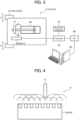
- FIG. 3 illustrates schematically an example of the main chuck 21.
- the main chuck 21 includes a reciprocating drive section, for example, a cylinder 26a and a piston rod 26b that drive the main chuck jaws 21a to an open or closed state, and a dog 27 as a detected section that is provided on the piston rod 26b, for example.
- FIG. 3 does not illustrate a mechanism that transforms orthogonally the reciprocating linear motion of the piston rod 26b into an opening/closing action of the main chuck jaws 21a in the opening/closing directions.
- the main sensor 25a is connected to a controller 100.
- the controller 100 controls the movement mechanism 60.
- the controller 100 outputs the movement instruction to make the chuck 20A to start to move in the Z-axis direction based on an output from the sensor 25a.
- the controller 100 may be connected to a numerical controller (NC) 200 that controls and performs processing of the workpiece W in accordance with a program upon completion of loading action of the loading device 20 based on the signal from the controller 100.
- the NC 200 may be connected to a personal computer (PC) 300, preferably the touch-panel PC.
- the PC 300 can perform data processing, display of processed data, data communication with other devices, and the like.
- FIG. 4 illustrates an example of the main sensor 25a.
- the main sensor 25a illustrated in FIG. 4 forms a magnetic field M by a plurality of coils built in the sensor body over the reciprocating range of the dog 27 to detect continuous changes in the magnetic field depending on the position of the dog 27.
- the main sensor 25a can detect the position of the dog 27 with a positional resolution of 1 mm or less even though the reciprocating range of the dog 27 is as short as 10 to 20 mm, for example.
- the sub chuck 22 of the first chuck 20A can also have the structure illustrated in FIG. 3 and the sub sensor 25b can also have the structure illustrated in FIG. 4 .
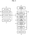
- FIG. 5 is a block diagram of a control system in the machine tool 1A.
- a controller 100 has a movement control section 110 that provides a movement instruction as illustrated in FIG. 2C to a movement mechanism 60 that moves the arm section 20B of the loading device 20 at least in the X- and Z-axis directions.
- the movement control section 110 is connected to the main sensor 25a and the sub sensor 25b constituting the first sensor 25 and the second sensor 15.
- the controller 100 can have a distance calculation section 120 connected to the main sensor 25a and the sub sensor 25b constituting the first sensor 25 and the second sensor 15.
- the distance calculation section 120 calculates the movement distance of the dog 27 provided on one of the first and second chucks 20A and 12 based on the output from one of the first and second sensors 25 and 15.
- the controller 100 can have a time measurement section 130 and a velocity calculation section 140.
- the velocity calculation section 140 accepts an input of time from the time measurement section 130 (for example, times t0, t2, t3, and t4 illustrated in FIG. 2C ) and the distance calculated by the distance calculation section 120 (for example, the distance between the open-end position and closed-end position illustrated in FIG. 2C ).
- the velocity calculation section 140 can calculate the velocity of the dog 27 (for example, velocities V1 and V2 illustrated in FIG. 2C ) provided on one of the first and second chucks 20A and 12 based on the input time and distance.
- the distance calculation section 120 can also detect a scope S of the open-end position or closed-end position illustrated in FIG. 2C .
- the opening and closing motion of the chuck jaws 12a, 21a, and 22a can be continuously detected by the digital sensors 15 and 25, which allows precision control based on the opened and closed positions of the chuck jaws 12a, 21a, and 22a.
- a determination section 150 determines the velocity detected by the velocity calculation section 140 so that it is easy to discover an abnormality in opening and closing of the chuck jaws 12a, 21a, and 22a.
- a warning section 70 connected to the determination section 150 can warn the abnormality by an alarm or the like.
- the determination section 150 can predict the time for parts replacement based on a temporal change of the opening and closing time and notify the time for parts replacement by the warning section 70.
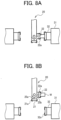
- FIGs. 6A to 8B illustrate examples of actions of the double-spindle-opposed lathe illustrated in FIG. 1 to which the loading device according to the present invention is applied.
- a right spindle 31 illustrated in the drawings includes a chuck 32 with chuck jaws 32a opened or closed.
- the chuck 32 has the same structure as illustrated in FIGs. 3 and 4 .
- the chuck 32 is also provided with a digital sensor.
- the timing chart illustrated in FIG. 2C is also applicable to the actions of chuck jaws 12a, 21a, and 22a described below.
- the spindle 11 and spindle 31 are opposed to each other on a Z-axis line. At least one of the two spindles 11 and 31, for example, the spindle 31 is controlled along the Z-axis direction in forward and backward movements. Referring to FIG. 6A , a workpiece W is held by the main chuck (first chuck) 21 of the loading device 20.
- the workpiece W gripped by the first chuck 21 of the loading device 20 is delivered to the chuck jaws 12a of the second chuck 12 in the spindle 11.
- an instruction for opening the first chuck 21 in the loading device 20 is output at the time t0 illustrated in FIG. 2C .
- the loading device 20 moves in the direction A1 away from the workpiece W as illustrated in FIG. 6C at the time t1 illustrated in FIG. 2C . Further, as illustrated in FIG. 7A , the loading device 20 is evacuated upward.
- the spindle 31 moves forward in an arrow A2 direction as illustrated in FIG. 7A to receive the workpiece W.
- an instruction for closing is output to the chuck 32 of the spindle 31.
- the workpiece W is gripped by the chuck jaws 32a.
- an instruction for opening is output to the chuck jaws 12a of the chuck 12 in the spindle 11.
- the digital sensor 15 in the chuck 12 detects the positions of the chuck jaws 12a during movement from the closed-end position to the open-end position.
- the spindle 32 moves in the arrow A1 direction away from the spindle 11 as illustrated in FIG. 7B at a time t5 illustrated in FIG. 2C . Accordingly, in the same manner as described above, the time for loading the workpiece W from the spindle 11 to the spindle 31 can be shortened. The spindle 31 moves backward to the original position.
- the chuck 20A in the loading device 20 rotates 90° in an arrow D direction around the shaft 24 as illustrated in FIG. 7B .
- the sub chuck 22 with the sub chuck jaws 22a receives the processed workpiece W as illustrated in FIG. 8A .
- the processed workpiece W is conveyed by the loading device 20 as illustrated in FIG. 8B .
- the loading device 20 can move in the direction away from the workpiece W (Z-axis direction) without waiting for the chuck jaws 32a of the chuck 32 to reach the open-end position. Accordingly, the loading time for delivering the workpiece W from the spindle 31 to the loading device 20 can be shortened as well.
- applying the loading device according to the present invention to a machine tool makes it possible to shorten the time for loading the workpiece W and improve productivity.
- the present invention is applied to a double-spindle-opposed lathe in the embodiment but is not limited to this.
- the present invention is also applicable to various machine tools with a loading device.
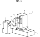
- FIG. 9 illustrates schematically another machine tool to which the present invention is applied.
- FIG. 9 illustrates a single-spindle turning center 1B with the loading device 20 illustrated in FIG. 2A .
- the spindle 11 and the loading device 20 can be provided with the digital sensor illustrated in FIGs. 3 and 4 .
Landscapes
- Engineering & Computer Science (AREA)
- Mechanical Engineering (AREA)
- Human Computer Interaction (AREA)
- Robotics (AREA)
- Feeding Of Workpieces (AREA)
- Turning (AREA)
Description
- The present invention relates to a machine tool using a loading device for delivery of a workpiece to and from the spindle of the machine tool according to
claim 1. - Machine tools such as lathes and complex processing machines have a chuck for gripping a workpiece at the leading end of a rotationally driven spindle.
- Loading devices delivering a workpiece to and from the spindle also have a chuck for gripping the workpiece.
- These chucks have dogs as detected sections for detecting the open end and closed end of chuck jaws. After the chuck of the spindle completely grips a workpiece, the chuck jaws of the chuck provided in the loading device are opened. The open end of the chuck jaws is detected by detecting the dogs, and then the chuck in the loading device is moved.
- However, to improve the throughput of a machine tool, it is required to further shorten the loading time.
- In addition, it is difficult to detect a malfunction such as reduction in the opening and closing speed of the chuck jaws only by detecting the open end and closed end of the chuck jaws.
-
JP-A-2005-186191 - However, a plurality of proximity switches arranged at specific intervals over the movement range of the dogs reciprocating together with the piston rod cannot be adopted in a loading device delivering a workpiece to and from the spindle of a machine tool due to space limitations.
- The document
DE 296 02 216 U1 discloses a gripping device with a housing, in which a central receiving hole and a lateral longitudinal recess are provided. In the recess sensors can be arranged for detecting end positions of a gripping unit being provided in the receiving hole. As sensors hall sensors or mechanical switches can be used. - Another gripping device is known from
DE 199 47 997 A1 . The gripping device comprises jaws being moveable by linearly movable pistons, one of which includes a magnet to be detected by a sensor arrangement. The rod-like sensor arrangement comprises two end sensors and one intermediate sensor for detecting end positions and one intermediate position. - A machine tool with a control unit is disclosed in
US 6,705,186 B2 . -
DE 3 813 708 A1 discloses robotic grippers in which the opening positions of the gripper fingers may be continuously monitored by means of Hall-sensor between a fully opened and a fully closed position of the gripper. An operator of the disclosed robot gripper may set different opening positions for the gripper fingers which then may selectively grip differently sized workpieces. If an operator would set two positions corresponding to a gripping and a releasing position of a workpiece, he would not find any hint to start a movement mechanism, such as the wrist or an arm of a robot, dependent on a position lying between the set two positions associated to the selected workpiece. -
DE 10 2015 012 779 A1 shows a comparable robotic gripper in which the fingers are controlled by an electric motor. The angular position of the electric motor is sensed by a Hall sensor. - In the robotic gripper of
EP 2 390 067 A1 two positions may be detected, wherein a fully open position and a gripping position is detected defining a range for gripping a workpiece. A third position lying outside the former range represents the gripper in its fully closed position in which no work piece is gripped. - An object of one aspect of the present invention is to provide a machine tool using a loading device that reduces time loss and shortens the loading time for delivering a workpiece to and from a spindle of the machine tool.
- The object is solved by a machine tool with a loading device with the features of
claim 1. Preferred embodiments are defined in the dependent claims. - According to the invention, there is provided a loading device comprising a chuck chucking a workpiece on chuck jaws that are opened and closed, and a movement mechanism moving the chuck and delivering the workpiece to and from a spindle of a machine tool,
- a sensor being provided to detect a continuously changing signal depending on an open-end position of the chuck jaws, a closed-end position of the chuck jaws, and movement position between the open-end position and the closed-end position,
- the movement mechanism being configured to move the chuck when the chuck jaws are in the movement position, based on an output from the sensor.
- The sensor here refers to any sensor that can detect a signal continuously changing depending on the positions of open end to closed end of the chuck jaws, which may be of a contact type in contact with the detected section or a non-contact type. The sensor is preferably a digital sensor that converts a continuously changing analog signal into a digital signal and outputs the same. The principle of detection by the sensor may be to detect a change in a magnetic field or a capacity depending on the positon of the detected section or detect reflection of a laser beam, infrared ray, or ultrasonic wave. Among them, a single sensor detecting a change in a magnetic field depending on the position of the detected section (magnetic body) is compact and inexpensive, and also favorably achieves a positional resolution of 1 mm or less even though the detected section has a relatively short movement range of 10 to 20 mm, for example.
- According to the loading device, based on the output from the sensor, when the chuck jaws are in a movement position before reaching the movement-completed position as the open-end position from the closed-end position, the movement mechanism can start the movement of the chuck as the next process.
- According to a conventional loading device, after a workpiece is chucked by the spindle, the chuck in the loading device needs to be held on standby until the opening of the chuck jaws in the loading device is completed. This causes time loss by the standby state of the loading device. According to one aspect of the present invention, before the completion of opening of the chuck jaws in the loading device is detected, the loading device can move to the next process to shorten the time of delivery of a workpiece and improve the efficiency of the loading.
- The present invention relates to a machine tool that has a spindle and a loading device. The loading device includes a first chuck and the spindle includes a second chuck. In this case, a first sensor identical to the sensor described above may be provided in the first chuck and a second sensor identical to the sensor described above may be provided in the second chuck.
- This makes it possible to start the movement of the first chuck by the movement mechanism based on a signal for detecting the closed-end position from one of the first and second sensors provided on one of the first and second chucks to receive a workpiece and a signal for detecting the movement from the closed-end positon to the movement position from the other of the first and second sensors provided on the other of the first and second chucks to pass the workpiece. This makes it possible to shorten the loading time both when the loading device passes a workpiece and when the loading device receives a workpiece.
- In still another aspect of the present invention, the movement distance of the chuck jaws is acquired based on the output from the sensor and the movement time is acquired from a time measurement section to detect the opening and closing speed of the chuck jaws.
- This makes it possible to detect reduction in the opening and closing speed of the chuck jaws and replace the parts in advance. In addition, it is possible to detect early the abnormal opening and closing of the chuck jaws and the lifetime of the chuck jaws.
-
-
FIG. 1 is a diagram illustrating a spindle-opposed turning center as an example of a complex machine tool to which the present invention is applied. -
FIGs. 2A and 2B are diagrams illustrating a structure example of a loading device for use in the present invention, andFIG. 2C is a diagram illustrating opening and closing motion of chuck jaws, the motion of the chuck jaws, and a movement instruction to a movement mechanism. -
FIG. 3 is a diagram illustrating the chuck jaws, a reciprocating drive section, and a sensor that are provided in a chuck, and a controller into which the output from the sensor is input. -
FIG. 4 is a diagram illustrating an example of a sensor that detects a continuously changing signal depending on the position of a detected section. -
FIG. 5 is a block diagram of a control system in the machine tool that performs control based on the output from the sensor. -
FIGs. 6A and 6B are diagrams illustrating a state in which the loading device passes a workpiece to a spindle, andFIG. 6C is a diagram illustrating a state in which, after the start of opening of the chuck jaws, the loading device moves directly. -
FIG. 7A is a diagram illustrating a state in which, after completion of processing of the workpiece on a spindle L, a spindle R moves to receive the workpiece, andFIG. 7B is a diagram illustrating a state in which the spindle R processes the workpiece. -
FIGs. 8A and 8B are diagrams illustrating a state in which the loading device receives the completed workpiece from the spindle R. -
FIG. 9 is a diagram illustrating a single-spindle turning center as another example of a complex machine tool to which the present invention is applied. - Exemplary embodiments of the invention are described in detail below. Note that the following embodiments do not in any way limit the scope of the invention defined by the claims laid out herein. Note also that all of the elements described in connection with the following embodiments should not necessarily be taken as essential elements of the invention.
-
FIG. 1 illustrates schematically a machine tool to which the present invention is applied.FIG. 1 illustrates a double-spindle-opposedturning center 1A in which right and left spindles are laterally opposed to each other. However,FIG. 1 does not illustrate a loading device. Referring toFIG. 1 , a workpiece (not shown) is held and rotated by aleft spindle 11 and/or aright spindle 31 controlled along a C axis. A tool attached to atool spindle 41 is capable of translational motion along X, Y, and Z axes orthogonal to one another (crossing in a board sense), and is capable of rotational motion around a B axis. Thespindle 11 is rotatably supported on aheadstock 10, and thespindle 31 is rotatably supported on aheadstock 30. Thetool spindle 41 is rotatably supported on atool post 40. Amovable carriage 50 is provided in a manner capable of translational motion in the Y- and Z-axis directions with respect to abase 1. Thetool post 40 is supported movably in the X-axis direction with respect to themovable carriage 50. -
FIG. 2A illustrates an example of a loading device of themachine tool 1A. Aloading device 20 is included as auxiliary equipment in themachine tool 1A. Theloading device 20 includes achuck 20A that chucks a workpiece W, anarm 20B that supports thechuck 20A, and a movement mechanism 60 (not illustrated inFIG.2A but illustrated inFIGs 3 and5 ) that moves thearm 20B at least in the X-axis direction and the Z-axis direction. - Referring to
FIG. 2A , the L-shaped chuck (also called first chuck) 20A, with amain chuck 21 and asub chuck 22 arranged in a direction at right angles to each other, is turnably coupled to the leading end of thearm 20B by ashaft 24. - The
main chuck 21 is switched between an open state in which the workpiece W can be delivered and a closed state in which the workpiece W is gripped, for example, by widening or narrowing threemain chuck jaws 21a in a radial direction. Thesub chuck 22 also has threesub chuck jaws 22a. - The
main chuck jaws 21a include a sensor, for example, adigital sensor 25a that can continuously detect the fully-open state, the fully-closed state, and the intermediate state. Thesub chuck jaws 22a also include adigital sensor 25b. Themain chuck jaws 21a and thesub chuck jaws 22a will be collectively called first chuck jaws. Thedigital sensors - Referring to
FIG. 2A , thespindle 11 is provided with asecond chuck 12. Thesecond chuck 12 has threesecond chuck jaws 12a that chuck the workpiece W, for example. Thesecond chuck jaws 12a can also be provided with a second sensor, for example, adigital sensor 15 that can continuously detect the fully-open state, the fully-closed state, and the intermediate state. -
FIG. 2A illustrates schematically a state in which the workpiece W is delivered from themain chuck 21 of theloading device 20 to thechuck 12 of thespindle 11.FIG. 2B illustrates schematically a state in which themain chuck jaws 21a are slightly opened in an arrow direction B under an instruction for opening themain chuck jaws 21a and thechuck 20A in theloading device 20 starts to move in an arrow direction A1 away from the workpiece W.FIG. 2C illustrates a signal for opening and closing themain chuck jaws 21a, the motion of themain chuck jaws 21a, and an movement instruction to amovement mechanism 60. - For example, upon an instructional signal for opening the
main chuck jaws 21a, themain chuck jaws 21a starts to change from the fully-closed state to the fully-open state at a time t0 illustrated inFIG. 2C , themain chuck jaws 21a move in opening directions B as illustrated inFIG. 2B . The movement of themain chuck jaws 21a is detected by thedigital sensor 25a. - When the
digital sensor 25a detects the movement of themain chuck jaws 21a from the closed-end position at a time t1 after the time t0 illustrated inFIG. 2C , a movement instruction is output to themovement mechanism 60 so that thechuck 20A in theloading device 20 starts to move in the arrow direction A1 away from the workpiece W as illustrated inFIG. 2B . - Accordingly, the
chuck 20A in theloading device 20 can start to move to the next process at the time t1 earlier than a time t2 when themain chuck jaws 21a reach the open-end position. As a result, time loss can be reduced by the time (t2 - t1) to shorten the loading time. -
FIG. 3 illustrates schematically an example of themain chuck 21. Themain chuck 21 includes a reciprocating drive section, for example, acylinder 26a and apiston rod 26b that drive themain chuck jaws 21a to an open or closed state, and adog 27 as a detected section that is provided on thepiston rod 26b, for example.FIG. 3 does not illustrate a mechanism that transforms orthogonally the reciprocating linear motion of thepiston rod 26b into an opening/closing action of themain chuck jaws 21a in the opening/closing directions. Themain sensor 25a is connected to acontroller 100. Thecontroller 100 controls themovement mechanism 60. For example, thecontroller 100 outputs the movement instruction to make thechuck 20A to start to move in the Z-axis direction based on an output from thesensor 25a. Thecontroller 100 may be connected to a numerical controller (NC) 200 that controls and performs processing of the workpiece W in accordance with a program upon completion of loading action of theloading device 20 based on the signal from thecontroller 100. TheNC 200 may be connected to a personal computer (PC) 300, preferably the touch-panel PC. ThePC 300 can perform data processing, display of processed data, data communication with other devices, and the like. -
FIG. 4 illustrates an example of themain sensor 25a. Themain sensor 25a illustrated inFIG. 4 forms a magnetic field M by a plurality of coils built in the sensor body over the reciprocating range of thedog 27 to detect continuous changes in the magnetic field depending on the position of thedog 27. Themain sensor 25a can detect the position of thedog 27 with a positional resolution of 1 mm or less even though the reciprocating range of thedog 27 is as short as 10 to 20 mm, for example. - In the embodiment, the
sub chuck 22 of thefirst chuck 20A can also have the structure illustrated inFIG. 3 and thesub sensor 25b can also have the structure illustrated inFIG. 4 . -
FIG. 5 is a block diagram of a control system in themachine tool 1A. Referring toFIG. 5 , acontroller 100 has amovement control section 110 that provides a movement instruction as illustrated inFIG. 2C to amovement mechanism 60 that moves thearm section 20B of theloading device 20 at least in the X- and Z-axis directions. Themovement control section 110 is connected to themain sensor 25a and thesub sensor 25b constituting thefirst sensor 25 and thesecond sensor 15. - The
controller 100 can have adistance calculation section 120 connected to themain sensor 25a and thesub sensor 25b constituting thefirst sensor 25 and thesecond sensor 15. Thedistance calculation section 120 calculates the movement distance of thedog 27 provided on one of the first andsecond chucks second sensors controller 100 can have atime measurement section 130 and avelocity calculation section 140. Thevelocity calculation section 140 accepts an input of time from the time measurement section 130 (for example, times t0, t2, t3, and t4 illustrated inFIG. 2C ) and the distance calculated by the distance calculation section 120 (for example, the distance between the open-end position and closed-end position illustrated inFIG. 2C ). Thevelocity calculation section 140 can calculate the velocity of the dog 27 (for example, velocities V1 and V2 illustrated inFIG. 2C ) provided on one of the first andsecond chucks distance calculation section 120 can also detect a scope S of the open-end position or closed-end position illustrated inFIG. 2C . - In such a manner as described above, the opening and closing motion of the
chuck jaws digital sensors chuck jaws determination section 150 determines the velocity detected by thevelocity calculation section 140 so that it is easy to discover an abnormality in opening and closing of thechuck jaws warning section 70 connected to thedetermination section 150 can warn the abnormality by an alarm or the like. In addition, thedetermination section 150 can predict the time for parts replacement based on a temporal change of the opening and closing time and notify the time for parts replacement by thewarning section 70. -
FIGs. 6A to 8B illustrate examples of actions of the double-spindle-opposed lathe illustrated inFIG. 1 to which the loading device according to the present invention is applied. Aright spindle 31 illustrated in the drawings includes achuck 32 withchuck jaws 32a opened or closed. Thechuck 32 has the same structure as illustrated inFIGs. 3 and 4 . Specifically, thechuck 32 is also provided with a digital sensor. The timing chart illustrated inFIG. 2C is also applicable to the actions ofchuck jaws - As illustrated in
FIG. 6A , thespindle 11 andspindle 31 are opposed to each other on a Z-axis line. At least one of the twospindles spindle 31 is controlled along the Z-axis direction in forward and backward movements. Referring toFIG. 6A , a workpiece W is held by the main chuck (first chuck) 21 of theloading device 20. - As illustrated in
FIG. 6B , the workpiece W gripped by thefirst chuck 21 of theloading device 20 is delivered to thechuck jaws 12a of thesecond chuck 12 in thespindle 11. - When the fully-closed state of the
chuck jaws 12a of thesecond chuck 12 is detected, an instruction for opening thefirst chuck 21 in theloading device 20 is output at the time t0 illustrated inFIG. 2C . Without waiting for thechuck jaws 21a of thefirst chuck 21 to reach the open-end position, theloading device 20 moves in the direction A1 away from the workpiece W as illustrated inFIG. 6C at the time t1 illustrated inFIG. 2C . Further, as illustrated inFIG. 7A , theloading device 20 is evacuated upward. - Upon completion of processing of the workpiece W using the
cutter rest 40 illustrated inFIG. 1 , thespindle 31 moves forward in an arrow A2 direction as illustrated inFIG. 7A to receive the workpiece W. In that instance, at the time t3 illustrated inFIG. 2C , an instruction for closing is output to thechuck 32 of thespindle 31. At the time t4 illustrated inFIG. 2C , the workpiece W is gripped by thechuck jaws 32a. - After that, an instruction for opening is output to the
chuck jaws 12a of thechuck 12 in thespindle 11. Then, thedigital sensor 15 in thechuck 12 detects the positions of thechuck jaws 12a during movement from the closed-end position to the open-end position. Without waiting for thechuck jaws 12a of thechuck 12 to reach the open-end position, thespindle 32 moves in the arrow A1 direction away from thespindle 11 as illustrated inFIG. 7B at a time t5 illustrated inFIG. 2C . Accordingly, in the same manner as described above, the time for loading the workpiece W from thespindle 11 to thespindle 31 can be shortened. Thespindle 31 moves backward to the original position. - Before completion of processing of the workpiece W gripped by the
spindle 31 using thecutter rest 40 illustrated inFIG. 1 , thechuck 20A in theloading device 20 rotates 90° in an arrow D direction around theshaft 24 as illustrated inFIG. 7B . After that, thesub chuck 22 with thesub chuck jaws 22a receives the processed workpiece W as illustrated inFIG. 8A . Then, the processed workpiece W is conveyed by theloading device 20 as illustrated inFIG. 8B . In that instance, theloading device 20 can move in the direction away from the workpiece W (Z-axis direction) without waiting for thechuck jaws 32a of thechuck 32 to reach the open-end position. Accordingly, the loading time for delivering the workpiece W from thespindle 31 to theloading device 20 can be shortened as well. - As described above, applying the loading device according to the present invention to a machine tool makes it possible to shorten the time for loading the workpiece W and improve productivity.
- Although only some embodiments of the present invention have been described in detail above, those skilled in the art will readily appreciate that many modifications are possible without departing from the scope of the invention as defined in the appended claims.
- For example, the present invention is applied to a double-spindle-opposed lathe in the embodiment but is not limited to this. The present invention is also applicable to various machine tools with a loading device.
-
FIG. 9 illustrates schematically another machine tool to which the present invention is applied.FIG. 9 illustrates a single-spindle turning center 1B with theloading device 20 illustrated inFIG. 2A . In theturning center 1B as well, thespindle 11 and theloading device 20 can be provided with the digital sensor illustrated inFIGs. 3 and 4 .
Claims (6)
- A machine tool comprising:a spindle (11); anda loading device delivering a workpiece (W) to and from the spindle (11),the loading device (20) including a first chuck (21) chucking the workpiece (W) on first chuck jaws (21a) that are opened and closed, and a movement mechanism (60) moving the first chuck (21),the spindle (11) including a second chuck (12) chucking the workpiece (W) on second chuck jaws (12a) that are opened and closed, characterized bythe first chuck (21) having:a first sensor (25a) detecting a continuously changing signal depending on an open-end position of the first chuck jaws (21a), a closed-end position of the first chuck jaws (21a), and a movement position between the open-end position and the closed-end position; anda controller (100) outputting a movement instruction to the movement mechanism (60) for starting to move the first chuck (21) when the first chuck jaws (21a) are in the movement position while moving from the closed-end position to the open-end position, based on an output from the first sensor (25a).
- The machine tool as defined in claim 1,
the first chuck (21) further having:a first reciprocating drive section driving the first chuck jaws (21a) to an open or closed state; anda first detected section provided on the first reciprocating drive section,the first sensor (25a) detecting the position of the first detected section within a reciprocating range of the first detected section. - The machine tool as defined in claim 2,
the second chuck (12) having a second sensor (15) detecting a continuously changing signal depending on an open-end position of the second chuck jaws (12a), a closed-end position of the second chuck jaws (12a), and a movement position between the open-end position and the closed-end position. - The machine tool as defined in claim 3,
the second chuck (12) further having:a second reciprocating drive section driving the second chuck jaws (12a) to an open or closed state; anda second detected section provided on the second reciprocating drive section,the second sensor (15) detecting the position of the second detected section within a reciprocating range of the second detected section. - The machine tool as defined in claim 3 or 4,
the controller (100) outputting the movement instruction to the movement mechanism (60) based on a signal for detecting the closed-end position from one of the first and second sensors provided on one of the first and second chucks (21, 12) to receive the workpiece (W) and a signal for detecting the movement from the closed-end position to the movement position from the other of the first and second sensors (25a, 15) provided on the other of the first and second chucks (21, 12) to pass the workpiece (W). - The machine tool as defined in any one of claims 3 to 5,
the controller (100) including:a time measurement section (130);a distance calculation section (120) calculating a movement distance of one of the first and second detected sections based on an output from one of the first and second sensors (25, 15); anda velocity calculation section (140) calculating the velocity of one of the first and second detected sections based on outputs from the time measurement section (130) and the distance calculation section (120).
Applications Claiming Priority (1)
| Application Number | Priority Date | Filing Date | Title |
|---|---|---|---|
| JP2017125402A JP6960659B2 (en) | 2017-06-27 | 2017-06-27 | Machine tool loading system |
Publications (2)
| Publication Number | Publication Date |
|---|---|
| EP3441204A1 EP3441204A1 (en) | 2019-02-13 |
| EP3441204B1 true EP3441204B1 (en) | 2023-08-02 |
Family
ID=62750798
Family Applications (1)
| Application Number | Title | Priority Date | Filing Date |
|---|---|---|---|
| EP18179208.6A Active EP3441204B1 (en) | 2017-06-27 | 2018-06-22 | Loading device and method tool using the same |
Country Status (2)
| Country | Link |
|---|---|
| EP (1) | EP3441204B1 (en) |
| JP (1) | JP6960659B2 (en) |
Citations (4)
| Publication number | Priority date | Publication date | Assignee | Title |
|---|---|---|---|---|
| DE3813708A1 (en) * | 1987-04-28 | 1988-11-17 | Wright Barry Corp | ROBOT POSITION SENSOR |
| WO2008067846A1 (en) * | 2006-12-04 | 2008-06-12 | Inpeco Ip Ltd. | Container gripper provided with a position sensor |
| EP2390067A1 (en) * | 2010-05-25 | 2011-11-30 | Günther Zimmer | Gripping device with electrodynamic positioning member |
| DE102015012779A1 (en) * | 2015-10-05 | 2017-04-27 | Günther Zimmer | Gripping device with integrated servo drive |
Family Cites Families (16)
| Publication number | Priority date | Publication date | Assignee | Title |
|---|---|---|---|---|
| DE3004988C2 (en) * | 1980-02-11 | 1987-10-01 | Gildemeister Ag, 4800 Bielefeld | Device for setting two final clamping positions that limit a clamping stroke |
| DE3105872C2 (en) * | 1981-02-18 | 1984-12-06 | Paul Forkardt GmbH & Co KG, 4000 Düsseldorf | Device for determining the working stroke of the piston of a double-acting clamping cylinder for actuating clamping devices on machine tools |
| JPS61164755A (en) * | 1985-01-08 | 1986-07-25 | Mitsubishi Electric Corp | Industrial robot hand device |
| JPH02243280A (en) * | 1989-03-14 | 1990-09-27 | Mitsubishi Electric Corp | Control method for industrial robot |
| JPH03131488A (en) * | 1989-10-09 | 1991-06-05 | Murata Mach Ltd | Article carrying device having robot hand and surface plate for article placement |
| JPH068098A (en) * | 1992-06-26 | 1994-01-18 | Amada Co Ltd | One plate taking device provided with two plate taking detecting device |
| JPH0740102A (en) * | 1993-07-23 | 1995-02-10 | Murata Mach Ltd | Loader device for double disc lathe |
| DE29602216U1 (en) * | 1996-02-09 | 1996-04-11 | Schunk Fritz Gmbh | Gripping device |
| DE29819943U1 (en) * | 1998-11-07 | 1999-02-18 | Festo Ag & Co | Fluid operated gripper |
| JP3293802B2 (en) * | 1999-07-07 | 2002-06-17 | エスエムシー株式会社 | Chuck with position detection function |
| JP2003071617A (en) * | 2001-09-05 | 2003-03-12 | Yamazaki Mazak Corp | Control device for machine tool |
| JP2004050321A (en) * | 2002-07-17 | 2004-02-19 | Ricoh Co Ltd | Gripping control process of robot hand, and gripping device |
| JP2005186191A (en) * | 2003-12-25 | 2005-07-14 | Mori Seiki Co Ltd | Machine tool |
| JP2006235224A (en) * | 2005-02-24 | 2006-09-07 | Fuji Photo Film Co Ltd | Photographing device |
| JP2016036880A (en) * | 2014-08-08 | 2016-03-22 | 村田機械株式会社 | Work carrying device and machine tool |
| JP6494499B2 (en) * | 2015-12-09 | 2019-04-03 | 三菱電機株式会社 | Numerical controller |
-
2017
- 2017-06-27 JP JP2017125402A patent/JP6960659B2/en active Active
-
2018
- 2018-06-22 EP EP18179208.6A patent/EP3441204B1/en active Active
Patent Citations (4)
| Publication number | Priority date | Publication date | Assignee | Title |
|---|---|---|---|---|
| DE3813708A1 (en) * | 1987-04-28 | 1988-11-17 | Wright Barry Corp | ROBOT POSITION SENSOR |
| WO2008067846A1 (en) * | 2006-12-04 | 2008-06-12 | Inpeco Ip Ltd. | Container gripper provided with a position sensor |
| EP2390067A1 (en) * | 2010-05-25 | 2011-11-30 | Günther Zimmer | Gripping device with electrodynamic positioning member |
| DE102015012779A1 (en) * | 2015-10-05 | 2017-04-27 | Günther Zimmer | Gripping device with integrated servo drive |
Also Published As
| Publication number | Publication date |
|---|---|
| JP2019005875A (en) | 2019-01-17 |
| EP3441204A1 (en) | 2019-02-13 |
| JP6960659B2 (en) | 2021-11-05 |
Similar Documents
| Publication | Publication Date | Title |
|---|---|---|
| KR102431825B1 (en) | Machine tool | |
| CN107363543B (en) | Machine tool | |
| JP4544145B2 (en) | Robot interference avoidance method and robot | |
| CN107378612B (en) | Machine tool | |
| TWI723301B (en) | Machine tool | |
| CN107443145B (en) | Machine tool | |
| CN109746911B (en) | Machining system | |
| CN107914305B (en) | Cutting method and cutting system | |
| JP5845311B2 (en) | Control device for flexible control of robots | |
| JP6252597B2 (en) | Robot system | |
| US20180067467A1 (en) | Machining system and robot system | |
| US20210039212A1 (en) | Machine tool | |
| JP2020536761A (en) | Robot device | |
| KR102547810B1 (en) | shelf | |
| CN105291103A (en) | Electric fixture | |
| EP3441204B1 (en) | Loading device and method tool using the same | |
| JP2007286688A (en) | Interference detection method and control device for machine tool | |
| US20110154962A1 (en) | Machine tool and machining method thereof | |
| JP6492426B2 (en) | Work holding confirmation device and work holding confirmation method | |
| JPH10254520A (en) | Original point returning method for nc control axis | |
| CN116490307B (en) | Method for pushing tailstock of machining device, computer program, and computer-readable storage medium | |
| US20240116099A1 (en) | A robotic tube bending machine | |
| US8688269B2 (en) | Apparatus for teaching a gripping device | |
| KR100299677B1 (en) | Device and method for high speed accessing multi-arm robot to welding object | |
| JP2023027515A (en) | Workpiece turnover device |
Legal Events
| Date | Code | Title | Description |
|---|---|---|---|
| PUAI | Public reference made under article 153(3) epc to a published international application that has entered the european phase |
Free format text: ORIGINAL CODE: 0009012 |
|
| STAA | Information on the status of an ep patent application or granted ep patent |
Free format text: STATUS: THE APPLICATION HAS BEEN PUBLISHED |
|
| AK | Designated contracting states |
Kind code of ref document: A1 Designated state(s): AL AT BE BG CH CY CZ DE DK EE ES FI FR GB GR HR HU IE IS IT LI LT LU LV MC MK MT NL NO PL PT RO RS SE SI SK SM TR |
|
| AX | Request for extension of the european patent |
Extension state: BA ME |
|
| STAA | Information on the status of an ep patent application or granted ep patent |
Free format text: STATUS: REQUEST FOR EXAMINATION WAS MADE |
|
| 17P | Request for examination filed |
Effective date: 20190808 |
|
| RBV | Designated contracting states (corrected) |
Designated state(s): AL AT BE BG CH CY CZ DE DK EE ES FI FR GB GR HR HU IE IS IT LI LT LU LV MC MK MT NL NO PL PT RO RS SE SI SK SM TR |
|
| STAA | Information on the status of an ep patent application or granted ep patent |
Free format text: STATUS: EXAMINATION IS IN PROGRESS |
|
| STAA | Information on the status of an ep patent application or granted ep patent |
Free format text: STATUS: EXAMINATION IS IN PROGRESS |
|
| 17Q | First examination report despatched |
Effective date: 20210111 |
|
| STAA | Information on the status of an ep patent application or granted ep patent |
Free format text: STATUS: EXAMINATION IS IN PROGRESS |
|
| GRAP | Despatch of communication of intention to grant a patent |
Free format text: ORIGINAL CODE: EPIDOSNIGR1 |
|
| STAA | Information on the status of an ep patent application or granted ep patent |
Free format text: STATUS: GRANT OF PATENT IS INTENDED |
|
| INTG | Intention to grant announced |
Effective date: 20230221 |
|
| GRAS | Grant fee paid |
Free format text: ORIGINAL CODE: EPIDOSNIGR3 |
|
| GRAA | (expected) grant |
Free format text: ORIGINAL CODE: 0009210 |
|
| STAA | Information on the status of an ep patent application or granted ep patent |
Free format text: STATUS: THE PATENT HAS BEEN GRANTED |
|
| AK | Designated contracting states |
Kind code of ref document: B1 Designated state(s): AL AT BE BG CH CY CZ DE DK EE ES FI FR GB GR HR HU IE IS IT LI LT LU LV MC MK MT NL NO PL PT RO RS SE SI SK SM TR |
|
| REG | Reference to a national code |
Ref country code: GB Ref legal event code: FG4D |
|
| REG | Reference to a national code |
Ref country code: CH Ref legal event code: EP |
|
| REG | Reference to a national code |
Ref country code: DE Ref legal event code: R096 Ref document number: 602018054405 Country of ref document: DE |
|
| REG | Reference to a national code |
Ref country code: IE Ref legal event code: FG4D |
|
| REG | Reference to a national code |
Ref country code: LT Ref legal event code: MG9D |
|
| REG | Reference to a national code |
Ref country code: NL Ref legal event code: MP Effective date: 20230802 |
|
| REG | Reference to a national code |
Ref country code: AT Ref legal event code: MK05 Ref document number: 1594156 Country of ref document: AT Kind code of ref document: T Effective date: 20230802 |
|
| PG25 | Lapsed in a contracting state [announced via postgrant information from national office to epo] |
Ref country code: GR Free format text: LAPSE BECAUSE OF FAILURE TO SUBMIT A TRANSLATION OF THE DESCRIPTION OR TO PAY THE FEE WITHIN THE PRESCRIBED TIME-LIMIT Effective date: 20231103 |
|
| PG25 | Lapsed in a contracting state [announced via postgrant information from national office to epo] |
Ref country code: IS Free format text: LAPSE BECAUSE OF FAILURE TO SUBMIT A TRANSLATION OF THE DESCRIPTION OR TO PAY THE FEE WITHIN THE PRESCRIBED TIME-LIMIT Effective date: 20231202 |
|
| PG25 | Lapsed in a contracting state [announced via postgrant information from national office to epo] |
Ref country code: SE Free format text: LAPSE BECAUSE OF FAILURE TO SUBMIT A TRANSLATION OF THE DESCRIPTION OR TO PAY THE FEE WITHIN THE PRESCRIBED TIME-LIMIT Effective date: 20230802 Ref country code: RS Free format text: LAPSE BECAUSE OF FAILURE TO SUBMIT A TRANSLATION OF THE DESCRIPTION OR TO PAY THE FEE WITHIN THE PRESCRIBED TIME-LIMIT Effective date: 20230802 Ref country code: PT Free format text: LAPSE BECAUSE OF FAILURE TO SUBMIT A TRANSLATION OF THE DESCRIPTION OR TO PAY THE FEE WITHIN THE PRESCRIBED TIME-LIMIT Effective date: 20231204 Ref country code: NO Free format text: LAPSE BECAUSE OF FAILURE TO SUBMIT A TRANSLATION OF THE DESCRIPTION OR TO PAY THE FEE WITHIN THE PRESCRIBED TIME-LIMIT Effective date: 20231102 Ref country code: NL Free format text: LAPSE BECAUSE OF FAILURE TO SUBMIT A TRANSLATION OF THE DESCRIPTION OR TO PAY THE FEE WITHIN THE PRESCRIBED TIME-LIMIT Effective date: 20230802 Ref country code: LV Free format text: LAPSE BECAUSE OF FAILURE TO SUBMIT A TRANSLATION OF THE DESCRIPTION OR TO PAY THE FEE WITHIN THE PRESCRIBED TIME-LIMIT Effective date: 20230802 Ref country code: LT Free format text: LAPSE BECAUSE OF FAILURE TO SUBMIT A TRANSLATION OF THE DESCRIPTION OR TO PAY THE FEE WITHIN THE PRESCRIBED TIME-LIMIT Effective date: 20230802 Ref country code: IS Free format text: LAPSE BECAUSE OF FAILURE TO SUBMIT A TRANSLATION OF THE DESCRIPTION OR TO PAY THE FEE WITHIN THE PRESCRIBED TIME-LIMIT Effective date: 20231202 Ref country code: HR Free format text: LAPSE BECAUSE OF FAILURE TO SUBMIT A TRANSLATION OF THE DESCRIPTION OR TO PAY THE FEE WITHIN THE PRESCRIBED TIME-LIMIT Effective date: 20230802 Ref country code: GR Free format text: LAPSE BECAUSE OF FAILURE TO SUBMIT A TRANSLATION OF THE DESCRIPTION OR TO PAY THE FEE WITHIN THE PRESCRIBED TIME-LIMIT Effective date: 20231103 Ref country code: FI Free format text: LAPSE BECAUSE OF FAILURE TO SUBMIT A TRANSLATION OF THE DESCRIPTION OR TO PAY THE FEE WITHIN THE PRESCRIBED TIME-LIMIT Effective date: 20230802 Ref country code: AT Free format text: LAPSE BECAUSE OF FAILURE TO SUBMIT A TRANSLATION OF THE DESCRIPTION OR TO PAY THE FEE WITHIN THE PRESCRIBED TIME-LIMIT Effective date: 20230802 |
|
| PG25 | Lapsed in a contracting state [announced via postgrant information from national office to epo] |
Ref country code: PL Free format text: LAPSE BECAUSE OF FAILURE TO SUBMIT A TRANSLATION OF THE DESCRIPTION OR TO PAY THE FEE WITHIN THE PRESCRIBED TIME-LIMIT Effective date: 20230802 |
|
| PG25 | Lapsed in a contracting state [announced via postgrant information from national office to epo] |
Ref country code: ES Free format text: LAPSE BECAUSE OF FAILURE TO SUBMIT A TRANSLATION OF THE DESCRIPTION OR TO PAY THE FEE WITHIN THE PRESCRIBED TIME-LIMIT Effective date: 20230802 |
|
| PG25 | Lapsed in a contracting state [announced via postgrant information from national office to epo] |
Ref country code: SM Free format text: LAPSE BECAUSE OF FAILURE TO SUBMIT A TRANSLATION OF THE DESCRIPTION OR TO PAY THE FEE WITHIN THE PRESCRIBED TIME-LIMIT Effective date: 20230802 Ref country code: RO Free format text: LAPSE BECAUSE OF FAILURE TO SUBMIT A TRANSLATION OF THE DESCRIPTION OR TO PAY THE FEE WITHIN THE PRESCRIBED TIME-LIMIT Effective date: 20230802 Ref country code: ES Free format text: LAPSE BECAUSE OF FAILURE TO SUBMIT A TRANSLATION OF THE DESCRIPTION OR TO PAY THE FEE WITHIN THE PRESCRIBED TIME-LIMIT Effective date: 20230802 Ref country code: EE Free format text: LAPSE BECAUSE OF FAILURE TO SUBMIT A TRANSLATION OF THE DESCRIPTION OR TO PAY THE FEE WITHIN THE PRESCRIBED TIME-LIMIT Effective date: 20230802 Ref country code: DK Free format text: LAPSE BECAUSE OF FAILURE TO SUBMIT A TRANSLATION OF THE DESCRIPTION OR TO PAY THE FEE WITHIN THE PRESCRIBED TIME-LIMIT Effective date: 20230802 Ref country code: CZ Free format text: LAPSE BECAUSE OF FAILURE TO SUBMIT A TRANSLATION OF THE DESCRIPTION OR TO PAY THE FEE WITHIN THE PRESCRIBED TIME-LIMIT Effective date: 20230802 Ref country code: SK Free format text: LAPSE BECAUSE OF FAILURE TO SUBMIT A TRANSLATION OF THE DESCRIPTION OR TO PAY THE FEE WITHIN THE PRESCRIBED TIME-LIMIT Effective date: 20230802 |