EP3437551B1 - Wideband acoustic immittance measurement apparatus - Google Patents
Wideband acoustic immittance measurement apparatus Download PDFInfo
- Publication number
- EP3437551B1 EP3437551B1 EP17184747.8A EP17184747A EP3437551B1 EP 3437551 B1 EP3437551 B1 EP 3437551B1 EP 17184747 A EP17184747 A EP 17184747A EP 3437551 B1 EP3437551 B1 EP 3437551B1
- Authority
- EP
- European Patent Office
- Prior art keywords
- acoustic
- res
- ear
- frequency
- immittance
- Prior art date
- Legal status (The legal status is an assumption and is not a legal conclusion. Google has not performed a legal analysis and makes no representation as to the accuracy of the status listed.)
- Active
Links
- 238000005259 measurement Methods 0.000 title claims description 116
- 210000000959 ear middle Anatomy 0.000 claims description 160
- 239000000523 sample Substances 0.000 claims description 85
- 230000003068 static effect Effects 0.000 claims description 75
- 210000000613 ear canal Anatomy 0.000 claims description 66
- 230000005236 sound signal Effects 0.000 claims description 57
- 238000002835 absorbance Methods 0.000 claims description 19
- 238000006243 chemical reaction Methods 0.000 claims description 6
- 238000003780 insertion Methods 0.000 claims description 6
- 230000037431 insertion Effects 0.000 claims description 6
- 230000004308 accommodation Effects 0.000 claims description 3
- 238000007789 sealing Methods 0.000 claims description 3
- 230000006870 function Effects 0.000 description 52
- RZVAJINKPMORJF-UHFFFAOYSA-N Acetaminophen Chemical compound CC(=O)NC1=CC=C(O)C=C1 RZVAJINKPMORJF-UHFFFAOYSA-N 0.000 description 30
- AYEKOFBPNLCAJY-UHFFFAOYSA-O thiamine pyrophosphate Chemical compound CC1=C(CCOP(O)(=O)OP(O)(O)=O)SC=[N+]1CC1=CN=C(C)N=C1N AYEKOFBPNLCAJY-UHFFFAOYSA-O 0.000 description 25
- 238000012360 testing method Methods 0.000 description 15
- 210000003454 tympanic membrane Anatomy 0.000 description 13
- 208000005923 otitis media with effusion Diseases 0.000 description 11
- 238000000034 method Methods 0.000 description 8
- 230000008901 benefit Effects 0.000 description 6
- 230000002829 reductive effect Effects 0.000 description 6
- 239000007787 solid Substances 0.000 description 6
- 239000004020 conductor Substances 0.000 description 5
- 210000003027 ear inner Anatomy 0.000 description 5
- 238000012512 characterization method Methods 0.000 description 4
- 210000005069 ears Anatomy 0.000 description 4
- 101100024036 Mus musculus Moxd2 gene Proteins 0.000 description 3
- 230000005540 biological transmission Effects 0.000 description 3
- 238000012545 processing Methods 0.000 description 3
- 230000011514 reflex Effects 0.000 description 3
- 238000012546 transfer Methods 0.000 description 3
- 230000008859 change Effects 0.000 description 2
- 210000003477 cochlea Anatomy 0.000 description 2
- 238000001514 detection method Methods 0.000 description 2
- 230000004886 head movement Effects 0.000 description 2
- 239000012528 membrane Substances 0.000 description 2
- 238000012216 screening Methods 0.000 description 2
- 208000000781 Conductive Hearing Loss Diseases 0.000 description 1
- 206010010280 Conductive deafness Diseases 0.000 description 1
- 241000282412 Homo Species 0.000 description 1
- 238000001295 Levene's test Methods 0.000 description 1
- 241000878128 Malleus Species 0.000 description 1
- 208000008719 Mixed Conductive-Sensorineural Hearing Loss Diseases 0.000 description 1
- 102100036467 Protein delta homolog 1 Human genes 0.000 description 1
- 230000002159 abnormal effect Effects 0.000 description 1
- 238000013459 approach Methods 0.000 description 1
- 238000004364 calculation method Methods 0.000 description 1
- 238000004891 communication Methods 0.000 description 1
- 208000023563 conductive hearing loss disease Diseases 0.000 description 1
- 230000008878 coupling Effects 0.000 description 1
- 238000010168 coupling process Methods 0.000 description 1
- 238000005859 coupling reaction Methods 0.000 description 1
- 230000003247 decreasing effect Effects 0.000 description 1
- 230000001419 dependent effect Effects 0.000 description 1
- 238000013461 design Methods 0.000 description 1
- 238000010586 diagram Methods 0.000 description 1
- 101150102995 dlk-1 gene Proteins 0.000 description 1
- 210000000883 ear external Anatomy 0.000 description 1
- 238000005516 engineering process Methods 0.000 description 1
- 210000002388 eustachian tube Anatomy 0.000 description 1
- 239000012530 fluid Substances 0.000 description 1
- 210000001785 incus Anatomy 0.000 description 1
- 230000000670 limiting effect Effects 0.000 description 1
- 210000002331 malleus Anatomy 0.000 description 1
- 238000012986 modification Methods 0.000 description 1
- 230000004048 modification Effects 0.000 description 1
- 206010033103 otosclerosis Diseases 0.000 description 1
- 230000007170 pathology Effects 0.000 description 1
- 230000008447 perception Effects 0.000 description 1
- 238000013102 re-test Methods 0.000 description 1
- 230000010255 response to auditory stimulus Effects 0.000 description 1
- 230000000717 retained effect Effects 0.000 description 1
- 238000012552 review Methods 0.000 description 1
- 230000035945 sensitivity Effects 0.000 description 1
- 210000001050 stape Anatomy 0.000 description 1
Images


Classifications
-
- A—HUMAN NECESSITIES
- A61—MEDICAL OR VETERINARY SCIENCE; HYGIENE
- A61B—DIAGNOSIS; SURGERY; IDENTIFICATION
- A61B5/00—Measuring for diagnostic purposes; Identification of persons
- A61B5/12—Audiometering
- A61B5/121—Audiometering evaluating hearing capacity
- A61B5/125—Audiometering evaluating hearing capacity objective methods
- A61B5/126—Audiometering evaluating hearing capacity objective methods measuring compliance or mechanical impedance of the tympanic membrane
-
- A—HUMAN NECESSITIES
- A61—MEDICAL OR VETERINARY SCIENCE; HYGIENE
- A61B—DIAGNOSIS; SURGERY; IDENTIFICATION
- A61B5/00—Measuring for diagnostic purposes; Identification of persons
- A61B5/72—Signal processing specially adapted for physiological signals or for diagnostic purposes
- A61B5/7235—Details of waveform analysis
Definitions
- a new wideband acoustic immitance measurement apparatus is provided.
- the middle ear is the portion of the ear internal to the tympanic membrane and external to the oval window of the inner ear.
- the middle ear comprises the tympanic membrane also denoted the ear drum, and the ossicles, i.e. the malleus, incus and stapes.
- the ossicles transfer vibrations of the tympanic membrane into waves in the fluid and membranes of the cochlea in the inner ear.
- the primary function of the middle ear is to efficiently transfer acoustic waves in the ear canal incident on the tympanic membrane to fluid-membrane waves within the cochlea.
- the middle ear efficiency peaks at a frequency of app. 1 kHz.
- the combined transfer function of the outer ear and middle ear of humans results in peak sensitivity to frequencies between 1 kHz and 3 kHz.
- Tympanometry sometimes also denoted immittance testing, is a well-known method of examining and diagnosing the middle ear. Tympanometry involves recording changes in middle ear admittance, while static pressure in the ear canal is varied.
- an ear probe is inserted in the ear canal in such a way that an air tight seal of the ear canal is provided.
- the ear probe has a loudspeaker for emission of sound, typically a 226 Hz pure tone, towards the tympanic membrane under varying static pressure in the ear canal inside the seal.
- the emitted sound causes vibration of the tympanic membrane and the ossicles of the middle ear, which in turn results in the conscious perception of hearing.
- Some of the emitted sound is reflected and picked up by a microphone of the ear probe.
- the tympanometer determines acoustic admittances of the middle ear based on the microphone signal and plots the determined acoustic admittances as a function of static pressure thereby forming a so-called tympanogram.
- the static pressure in the ear canal is the same as ambient pressure, and also under normal conditions, the static pressure in the middle ear is approximately the same as ambient pressure since the Eustachian tube opens periodically to ventilate the middle ear and to equalize pressure.
- the maximum sound is transmitted through the middle ear when the static pressure in the ear canal is equal to the pressure in the middle ear also denoted the tympanic peak pressure TPP.
- the frequency of the pure tone is also varied.
- sweep pressure method the frequency of the pure tone is held constant while the static pressure is varied; and with the so-called sweep frequency method, the static pressure is held constant at specified intervals while the frequency of the pure tone is varied.
- middle ear pathologies alter tympanometric shapes and shift the resonance frequency of the middle ear. For example, increases in stiffness due to otosclerosis can shift middle ear resonance to a higher than normal frequency, and increases in mass (or lack of stiffness) due to ossicular discontinuity can shift middle ear resonance to a lower than normal frequency.
- the ear probe In order to perform tympanometry, the ear probe is connected with a cable to a so-called tympanometer, which controls the tympanometry procedure. The measurement results are recorded by the tympanometer.
- the cable typically includes electrical conductors for interconnection of the microphone and a loudspeaker and switches and possible indicators, respectively, of the ear probe.
- the cable also has an air conduit for interconnection with a pump of the tympanometer for control of the static pressure in the ear canal subjected to the tympanometry test.
- a hand-held ear probe may be used for screening purposes, while an ear probe that is retained more securely in or at the ear canal of a human is typically preferred for clinical tests.
- Robert H. Margolis and Hortensia G. Goycoolea “Multifrequency Tympanometry in Normal Adults", Ear and Hearing 14 (6): 408 - 413, December 1993 , discloses recording of multifrequency tympanograms from 56 ears of 28 normal-hearing adult subjects to obtain normative data and to determine abnormal criteria for tympanometric measures. Static admittance, tympanometric width, and tympanometric peak pressure at 226 Hz were analysed along with eight different estimates of the resonant frequency of the middle ear. Based on test-retest reliability and normal distribution characteristics, preferred methods for clinical estimation of resonant frequency were determined.
- the sweep pressure mode i.e.
- ear canal pressure is swept while probe frequency is held constant, is preferred for detection of abnormally high resonant frequencies.
- the sweep frequency mode i.e. probe frequency is swept while ear canal air pressure is held constant, is preferred for identification of abnormally low resonant frequencies.
- Compensation for ear canal volume at +200 daPa was preferred over other compensation methods for estimation of middle ear resonant frequency.
- EP 3 053 522 A1 discloses an audiologic test apparatus that includes a pump device for fluidic communication with an ear canal of a subject, wherein the pump device is configured to apply a first pressure to the ear canal; a signal generator; and a processing module for communicatively coupling to the pump device and the signal generator, wherein the processing module is configured to obtain first acoustic parameter values indicative of an acoustic parameter at the first pressure based on a first broadband signal generated using the signal generator; wherein the pump device is configured to change the pressure in the ear canal from the first pressure to a second pressure, and apply a third pressure to the ear canal; wherein the signal generator is configured to generate a first tone signal during the pressure change from the first pressure to the second pressure; and wherein the processing module is configured to obtain third acoustic parameter values indicative of the acoustic parameter at the third pressure based on a third broadband signal generated using the signal generator, and determine a middle ear resonance frequency based on the first acoustic
- a new wideband acoustic immittance measurement apparatus for determination of wideband acoustic immittance in an ear of a human is provided for characterization of the middle ear of the human.
- the new wideband acoustic immittance measurement apparatus is configured for determination of wideband acoustic immittance with an ear probe inserted in the ear of the human, and for characterizing the middle ear by identifying one or more middle ear resonances, if any, based on the determined wideband acoustic immittance .
- the criteria for identification of a middle ear resonance are based on the realisation that middle ear resonances have characteristics that are similar to the characteristics of the resonance of a Helmholtz resonator, or network of Helmholtz resonators.
- a middle ear resonance may be identified based on a comparison of characteristics of the determined wideband acoustic immitance with corresponding characteristics at the resonance frequency f 0 of the Helmholtz resonator, or one resonance frequency f 0 of the network of Helmholtz resonators, of the corresponding wideband acoustic immittance determined for the Helmholtz resonator, or network of Helmholtz resonators.
- acoustic immittance measurements are performed with an ear probe positioned in the ear of the human for emission of sound towards the tympanic membrane at the end of the ear canal.
- the new wideband acoustic immittance measurement apparatus for determination of wideband acoustic immittance in the ear of the human comprises an ear probe for insertion in the ear of the human and having
- the ear probe may accommodate one of, or both of, the loudspeaker and the microphone.
- the new wideband acoustic immittance measurement apparatus for determination of wideband acoustic immittance in the ear of the human may comprise an ear probe for insertion in an ear canal of the human and having the loudspeaker for conversion of the output audio signal into the sound, and the microphone for generation of the input audio signal as a function of sound pressure at the microphone.
- the new wideband acoustic immittance measurement apparatus may have a housing separate from the ear probe for accommodation of one of, or both of, the loudspeaker and the microphone.
- the housing When operated, the housing is interconnected with the ear probe with a cable that contains electrical wires for interconnection with the microphone and/or the loudspeaker when accommodated in the ear probe and that contains air conduits for acoustic interconnection of the microphone and/or the loudspeaker when accommodated in the housing with the respective acoustic input port and acoustic output port of the ear probe.
- the sound delivery system of the wideband acoustic immittance measurement apparatus To determine acoustic immittance of the middle ear, the sound delivery system of the wideband acoustic immittance measurement apparatus must be known.
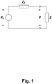
- Fig. 1 shows a Thevenin equivalent circuit for an immitance measurement performed with an ear probe.
- the sound source of the ear probe is modelled by an ideal sound pressure generator P 0 , i.e. a sound pressure generator with zero source impedance, in series with a source impedance Z 0 , which is connected in series with the acoustic load Z.
- P 0 a sound pressure generator with zero source impedance
- Measurements of sound pressure P at two different acoustic loads with known acoustic impedances Z A and Z B allow the calculation of the two equivalent circuit parameters of the sound source P 0 and Z 0 .
- One way to estimate the parameters P 0 and Z 0 of the sound source in an overdetermined equation system is to utilize a least-squares approach.
- acoustic immittance Z Based on the determined acoustic impedance Z , other acoustic immittances may be derived, such as:
- the wideband acoustic immittance determined by the wideband acoustic immittance measurement apparatus may be any function that can be determined based on measurement with the ear probe, including the acoustic immittances mentioned above, namely acoustic admittance Y(f), acoustic impedance Z(f), acoustic reflectance ⁇ (f) , acoustic energy reflectance ER(f), and acoustic energy absorbance EA(f).
- the real part of the acoustic admittance Y(f) is the conductance G(f), and the imaginary part of the acoustic admittance Y(f) is the susceptance B(f).
- the new wideband acoustic immittance measurement apparatus may provide characterization of the middle ear of a human based on the determined complex acoustic admittance Y(f), e.g. based on the conductance G(f) and the susceptance B(f) of the acoustic admittance Y(f); or, based on the acoustic admittance magnitude
- the real part of the acoustic impedance Z(f) is the resistance R(f), and the imaginary part of the acoustic impedance Z(f) is the reactance X(f).
- the new wideband acoustic immittance measurement apparatus may provide characterization of the middle ear of a human based on the determined complex acoustic impedance Z(f), e.g. based on the resistance R(f) and the reactance X(f) of the acoustic impedance Z(f); or, based on the acoustic impedance magnitude
- the new wideband acoustic immittance measurement apparatus for determination of wideband acoustic immittance in the ear of the human comprises a processor that is adapted for
- maximum means a global maximum or a local maximum
- minimum means a global minimum or a local minimum
- the determined wideband acoustic immittance is the acoustic admittance Y(f).
- the criteria for identification of a middle ear resonance are based on the realisation that middle ear resonances have characteristics similar to corresponding characteristics of the resonance of a Helmholtz resonator, or network of Helmholtz resonators.
- the Helmholtz resonator conductance is a global maximum of the Helmholtz resonator conductance (f) as a function of frequency; and the Helmholtz resonator gradient is a global minimum of the gradient of the Helmholtz resonator susceptance as a function of frequency.
- the Helmholtz resonator acoustic admittance magnitude is a global maximum of the Helmholtz resonator admittance magnitude as a function of frequency; and the Helmholtz resonator phase gradient is a global minimum of the Helmholtz resonator phase gradient as a function of frequency.
- the immitance may be represented by the real and imaginary part of the immitance ; or, equivalently by the acoustic immittance magnitude and acoustic immittance phase; and other equivalent representations of the acoustic immittance may be conceived with corresponding equivalent identification criteria for identification of a middle ear resonance.
- the determined wideband acoustic immittance may be another acoustic immittance than the acoustic admittance Y(f), such as the acoustic impedance Z(f), the acoustic reflectance ⁇ (f), the acoustic energy reflectance ER (f), the acoustic absorbance A(f), or any other function that can be determined based on the output audio signal and the input audio signal, and criteria for identification of a middle ear resonance corresponding to, or calculated from, the criteria for the acoustic admittance Y(f) may be established based on the relations between the different acoustic immittances, e.g.
- a real part or a magnitude part or an imaginary part or a phase part or a gradient of one of the parts, etc. with the corresponding part of the wideband acoustic immittance of a Helmholtz resonator, or network of Helmholtz resonators, for identifying one or more middle ear resonances, if any, based on the wideband acoustic immittance , each of which has characteristics of the wideband acoustic immittance similar to the characteristics of the corresponding wideband acoustic immittance of the Helmholtz resonator, or network of Helmholtz resonators, at the resonance of the Helmholtz resonator, or network of Helmholtz resonators.
- the resonance frequency f res of a middle ear resonance may be determined with some tolerance.
- the determined wideband acoustic immittance is the acoustic admittance Y(f).
- corresponding determinations of a first frequency f res,1 and a second frequency f res,2 may of course be performed for other determined wideband acoustic immittances , such as the acoustic impedance Z(f), the acoustic reflectance ⁇ (f), the acoustic energy reflectance ER(f), the acoustic absorbance A(f), or any other function that can be determined based on the output audio signal and the input audio signal, and criteria for identification of a middle ear resonance corresponding to, or calculated from, the criteria for the acoustic admittance Y(f) may be established based on the relations between the different acoustic immittances, e.g. see equations (5) - (9) above
- the processor may be adapted for identifying a resonance of one or more middle ear resonances, if any, by determining a first frequency f res,1 of a maximum, i.e. a local or a global maximum, of, e.g., the conductance G(f) of the determined acoustic admittance Y(f) as a function of frequency f.
- the processor may be adapted for identifying the local or global maximum at the first frequency f res,1 as a middle ear resonance, and f res,1 as the resonance frequency of the middle ear resonance.
- the processor may be adapted for identifying a resonance of one or more middle ear resonances, if any, by determining a second frequency f res,2 of a local or global minimum of a gradient of, e.g., the susceptance B(f) of the complex acoustic admittance Y(f) as a function of frequency f, and f res,2 as the resonance frequency of the middle ear resonance.
- the processor may be adapted for identifying a resonance of one or more middle ear resonances, by comparing the first frequency f res,1 with the second frequency f res,2 , and only if the frequencies f res,1 and f res,2 are identical, or identical apart from measurement inaccuracies and, optionally, some margin, identifying the local or global maximum as a middle ear resonance, i.e.
- a threshold value such as 10 %, such as 5 %, such as 2 %, of the first f res,1 or second frequency f res,2 .
- the new wideband acoustic immittance measurement apparatus It is an important advantage of the new wideband acoustic immittance measurement apparatus that an air tight seal of the ear canal need not be provided with the ear probe since the determination of the wideband acoustic immittance , e.g. the acoustic admittance Y(f), can take place at ambient pressure. Provision of an air tight seal of the ear canal is cumbersome and time consuming and often the air tight seal is not established in a first attempt. This makes the determination of the wideband acoustic immittance with the new wideband acoustic immitance measurement apparatus particularly useful for children that often have difficulties avoiding head movements during the determination of wideband acoustic immittance .
- the new wideband acoustic immittance measurement apparatus may also determine the wideband acoustic immittance , e.g. acoustic admittance Y(f, p), when a static pressure p different from ambient pressure p amb is applied to the ear canal, for identification of one or more middle ear resonances, if any.
- the wideband acoustic immittance e.g. acoustic admittance Y(f, p)
- a mentioning of a wideband acoustic immittance without the static pressure p means that the immittance in question; e.g. the acoustic admittance Y(f), acoustic impedance Z(f), acoustic reflectance ⁇ (f), acoustic energy reflectance ER(f), acoustic energy absorbance EA(f), or any other function that can be determined based on the output audio signal and the input audio signal, has been determined at ambient pressure p amb .
- the wideband acoustic immittance measurement apparatus may comprise a housing for accommodation of an air pump or compressor for provision of a static pressure p
- the ear probe may have a static pressure output port and an air conduit connected to the static pressure output port
- the cable interconnecting the housing of the apparatus with the ear probe may comprise an air conduit for interconnection of the air conduit of the ear probe with the air pump or compressor for applying the static pressure p to the ear canal with the ear probe forming an air tight seal with the ear canal wall so that the static pressure p in the ear canal can be controlled utilizing the air pump or compressor.
- the processor may further be adapted for performing wide band acoustic immittance measurements by controlling the air pump to provide static pressures p spanning a static pressure range, and determining the wideband acoustic immittance as a function of frequency f and static pressure p based on the output audio signal and the input audio signal and the provided static pressure p, such as the complex acoustic admittance Y(f, p), the complex acoustic impedance Z(f, p), the complex acoustic reflectance ⁇ (f, p), the complex acoustic energy reflectance ER(f, p), the complex acoustic energy absorbance EA(f, p), or any other function that can be determined based on the output audio signal and the input audio signal and the static pressure p.
- the complex acoustic admittance Y(f, p) the complex acoustic impedance Z(f, p)
- the criteria for identification of a middle ear resonance are based on the realisation that middle ear resonances have characteristics that are similar to the characteristics of the resonance of a Helmholtz resonator, or network of Helmholtz resonators.
- the Helmholtz resonator conductance is a global maximum of the Helmholtz resonator conductance (f) as a function of frequency; and the Helmholtz resonator gradient is a global minimum of the gradient of the Helmholtz resonator susceptance as a function of frequency.
- the Helmholtz resonator acoustic admittance magnitude is a global maximum of the Helmholtz resonator admittance magnitude as a function of frequency; and the Helmholtz resonator phase gradient is a global minimum of the Helmholtz resonator phase gradient as a function of frequency.
- the immitance may represented by the real and imaginary part of the immitance; or, equivalently by the acoustic immittance magnitude and acoustic immittance phase; and other equivalent representations of the acoustic immittance may be conceived with corresponding equivalent identification criteria for identification of a middle ear resonance.
- the determined wideband acoustic immittance is the acoustic admittance Y(f, p); however, the determined wideband acoustic immittance may be another acoustic immittance than the acoustic admittance Y(f, p), such as the acoustic impedance Z(f, p), the acoustic reflectance ⁇ (f, p), the acoustic energy reflectance ER(f, p), the acoustic absorbance A(f, p), or any other function that can be determined based on the output audio signal and the input audio signal, and criteria for identification of a middle ear resonance corresponding to, or calculated from, the criteria for the acoustic admittance Y(f, p) may be established based on the relations between the different acoustic immittances, e.g.
- the processor may be adapted for identifying one or more middle ear resonances, if any, based on a comparison of one part of the determined wideband acoustic immittance , e.g. a real part or a magnitude part or an imaginary part or a phase part or a gradient of one of the parts, etc., with the corresponding part of the wideband acoustic immittance determined for a Helmholtz resonator, or network of Helmholtz resonators, for identifying one or more middle ear resonances, if any, at respective resonance frequencies f res at which the wideband acoustic immittance has characteristics similar to the characteristics of the corresponding wideband acoustic immittance of the Helmholtz resonator, or network of Helmholtz resonators, at the resonance frequency f 0 of the Helmholtz resonator, or at a resonance f 0 of the network of Helmholtz resonators
- the resonance frequency f res of a middle ear resonance may be determined with some tolerance.
- the determined wideband acoustic immittance is the acoustic admittance Y(f, p).
- corresponding determinations of a first frequency f res,1 and a second frequency f res,2 may of course be performed for other determined wideband acoustic immittances , such as the acoustic impedance Z(f, p), the acoustic reflectance ⁇ (f, p), the acoustic energy reflectance ER(f, p), the acoustic absorbance A(f, p), or any other function that can be determined based on the output audio signal and the input audio signal, and criteria for identification of a middle ear resonance corresponding to, or calculated from, the criteria for the acoustic admittance Y(f, p) may be established based on the relations between the different acoustic immittances, e.g. see equations (5) - (9) above
- the processor may be adapted for identifying a resonance of one or more middle ear resonances, if any, by determining a first frequency f res,1 of a maximum, i.e. a local or a global maximum, of, e.g., the conductance G(f, p) of the determined acoustic admittance Y(f, p) as a function of frequency f.
- a first frequency f res,1 of a maximum i.e. a local or a global maximum, of, e.g., the conductance G(f, p) of the determined acoustic admittance Y(f, p) as a function of frequency f.
- the processor may be adapted for identifying the local or global maximum at the first frequency f res,1 as a middle ear resonance, and f res,1 as the resonance frequency of the middle ear resonance.
- the processor may be adapted for identifying a resonance of one or more middle ear resonances, if any, by determining a second frequency f res,2 of a local or global minimum of a gradient of, e.g., the susceptance B(f, p) of the complex acoustic admittance Y(f, p) as a function of frequency f, and f res,2 as the resonance frequency of the middle ear resonance.
- the processor may be adapted for identifying a resonance of one or more middle ear resonances, by comparing the first frequency f res,1 with the second frequency f res,2 , and only if the frequencies f res,1 and f res,2 are identical, or identical apart from measurement inaccuracies and, optionally, some margin, identifying the local or global maximum as a middle ear resonance, i.e.
- a threshold value such as 10 %, such as 5 %, such as 2 %, of the first f res,1 or second frequency f res,2 .
- the processor may be adapted for performing the determination of wideband acoustic immittance applying static pressures p through the ear probe, such as static pressures of 0 daPa, TPP, 200 daPa, - 400 daPa, etc.
- the determination of the wideband acoustic immittance , e.g. the acoustic admittance Y(f), of the ear includes the acoustic immittance of the ear canal, e.g. the acoustic admittance Y EC (f) of the ear canal.
- the ear canal is however redundant to the characteristics of the middle and inner ear and therefore it may be desirable to eliminate or reduce the contribution of the ear canal from the determined wideband acoustic immittance , e.g. acoustic admittance Y(f), before identification of one or more middle ear resonances, if any.
- the determination the acoustic admittance Y(f), of the ear includes the acoustic admittance Y EC (f) of the ear canal.
- the ear canal is however redundant to the characteristics of the middle and inner ear and therefore it may be desirable to eliminate or reduce the contribution Y EC (f) of the ear canal before identification of a middle ear resonance.
- p ref static pressure
- a primary middle ear resonance frequency is identified based on the baseline compensated acoustic admittance at the frequency at which the baseline compensated susceptance B BC (f, p ref ) is equal to 0 mmho.
- the new wideband acoustic immittance measurement apparatus is configured for identifying middle ear resonances based on baseline compensation in a new and accurate way as further explained below, so that the inaccuracy of known baseline compensation has been eliminated or reduced.
- Corresponding baseline compensations may be performed for another immittance, such as the acoustic impedance Z(f), the acoustic reflectance ⁇ (f), the acoustic energy reflectance ER (f), the acoustic absorbance A(f), etc.
- another immittance such as the acoustic impedance Z(f), the acoustic reflectance ⁇ (f), the acoustic energy reflectance ER (f), the acoustic absorbance A(f), etc.
- the first static pressure p 1 may be the ambient pressure p amb ; or, the first static pressure p 1 may be the tympanic peak pressure TPP, etc.
- the second static pressure p 2 may be 200 daPa; or, the second static pressure p 2 may be - 400 daPa, etc.
- the frequency range of the output audio signal, and thereby the emitted sound may include the frequency range from 200 Hz - 3 kHz.
- the frequency range of the output audio signal, and thereby the emitted sound may include the frequency range from 200 Hz - 4 kHz.
- the processor may be adapted for controlling a display, e.g. a printer, a display screen, etc., to show a plot of the determined acoustic immittance and/or and/or with one or more identifications of corresponding one or more middle ear resonances.
- a display e.g. a printer, a display screen, etc.
- the new wideband acoustic immittance measurement apparatus is not dependent on accurate calibration.
- the new wideband acoustic immittance measurement apparatus may be a self-contained unit with its own user interface with switches and a display, possibly a keyboard, as is well-known in the art of immittance measurement apparatuses.
- the new wideband acoustic immittance measurement apparatus may also be based on a general purpose computer, such as a PC, laptop, PDA, smartphone, etc., for recording to the test results and that comprises the user interface of the wideband acoustic immittance measurement apparatus and that is interconnected with and controls a special purpose apparatus with the required measurement circuitry and devices for performing the determination of wideband acoustic immittance in the ear of the human.
- a general purpose computer such as a PC, laptop, PDA, smartphone, etc.
- the recorded test results may be stored together with the identification of the right ear or the left ear that the stored test results relate to in the wideband acoustic immittance measurement apparatus and possibly other relevant information, such as the date, time, patient ID, operator ID, etc.
- the recorded data may be transferred to another device, such as a remote storage, such as a server interconnected with the wideband acoustic immittance measurement apparatus through a Wide Area Network, such as the Internet.
- a remote storage such as a server interconnected with the wideband acoustic immittance measurement apparatus through a Wide Area Network, such as the Internet.
- the ear probe may be connected with a cable to the wideband acoustic immittance measurement apparatus in a well-known way.
- the cable may include electrical conductors for interconnection of a microphone and a loudspeaker and switches and possible indicators, respectively, accommodated in the probe housing.
- the cable may also have an air conduit for interconnection with a pump in the wideband acoustic immittance measurement apparatus for control of the static pressure in the ear canal subjected to clinical testing or screening in a way well-known in the art of acoustic immitance measurements.
- the ear probe preferably comprises a conventional ear probe tip that is preferably configured for fitting with an ear tip for insertion into an ear canal of the patient and for sealing the ear canal with an air tight seal.
- the ear probe tip may provide an output of an air conduit connected with the air conduit of the cable to the wideband acoustic immittance measurement apparatus.
- the ear tip may be disposable and for example made of rubber.
- the results of the ear measurements performed with the wideband acoustic immittance measurement apparatus and the ear probe are recorded by the wideband acoustic immittance measurement apparatus and stored in a memory of the wideband acoustic immittance measurement apparatus.
- the results are stored together with an indication of whether the right ear or the left ear was subject to the testing as selected with the user interface.
- Fig. 2 schematically illustrates one example of the new wideband acoustic immittance measurement apparatus 10 with the ear probe 12 positioned with its acoustic output port at or inside an ear canal 100 of an ear 110 of a human.
- the ear probe 12 of the illustrated wideband acoustic immittance measurement apparatus 10 has an acoustic output port (not visible) for emission of sound towards the tympanic membrane 112 of the ear 110 and an acoustic input port (not visible) for reception of sound in the ear 110.
- a housing 14 of the wideband acoustic immittance measurement apparatus 10 accommodates a loudspeaker 16 for emission of the sound.
- a cable 18 interconnects the housing 14 with the ear probe 12 and has an air conduit 20 for transmission of the acoustic sound from the loud speaker 16 in the housing 14 to the acoustic output port (not visible) of the ear probe 12.
- the housing 14 further accommodates a microphone 22 for generation of an input audio signal 26 as a function of sound received at the acoustic input port of the ear probe 12.
- the cable 18 has an air conduit 24 for transmission of the sound received at the acoustic input port of the ear probe 12 to the microphone 22 for conversion into the corresponding input audio signal 26.
- the housing 14 further accommodates a processor 28 that is adapted for controlling the loudspeaker 16 to emit sound spanning a frequency range by generation of an output audio signal 30 that is input to the loudspeaker 16 for conversion into the corresponding emitted sound transmitted through the air conduit 20 of the cable 18 and through the acoustic output port (not visible) of the ear probe 12 and into the ear canal 100 for propagation towards the tympanic membrane 112 at the end of the ear canal 100.
- a processor 28 that is adapted for controlling the loudspeaker 16 to emit sound spanning a frequency range by generation of an output audio signal 30 that is input to the loudspeaker 16 for conversion into the corresponding emitted sound transmitted through the air conduit 20 of the cable 18 and through the acoustic output port (not visible) of the ear probe 12 and into the ear canal 100 for propagation towards the tympanic membrane 112 at the end of the ear canal 100.
- the processor 28 is also connected to the output of the microphone 22 for reception of the input audio signal 26 generated by the microphone 22 in response to sound received at the input port of the ear probe 12.
- the housing 14 accommodates both of the loudspeaker 16 and the microphone 22.
- the ear probe 12 accommodates the loudspeaker 16 and the microphone 22, and wherein the air conduits 20, 24 are substituted with electrical conductors for electrical connection of the input audio signal 26 and the output audio signal 30, respectively, with the microphone and the loudspeaker in the ear probe.
- the ear probe accommodates one of the loudspeaker 16 and the microphone 22, and wherein the corresponding air conduit 20, 24 is substituted with an electrical conductor for connection of the respective one of the input audio signal 26 and the output audio signal 30 to the one of the loudspeaker 16 and the microphone 22.
- the illustrated wideband acoustic immittance measurement apparatus 10 has an air pump or compressor 36 accommodated in the housing 14 for provision of a static pressure p in the ear canal 100.
- the processor 28 is adapted for controlling the static pressure p provided by the air pump or compressor 36 with control signal 34.
- the static pressure p is applied to the ear canal through an air conduit 38 of the cable 18 and through an air conduit (not visible) through the ear probe 12.
- the ear probe 12 seals the ear canal 100 with an air tight seal so that the static pressure p in the ear canal 100 can be adjusted with the air pump or compressor 36 as controlled by the processor 28.
- the processor 28 is adapted for determining a wideband acoustic immittance of the ear 110 based on the audio output signal 30 and the input audio signal 26, optionally at one or more static pressures p.
- the processor 28 is adapted for identifying a middle ear resonance by comparing characteristics of the determined immittance with the characteristics of a resonance of a Helmholtz resonator, or a network of Helmholtz resonators, of a corresponding immittance of the Helmholtz resonator, or network of Helmholtz resonators.
- the determined wideband acoustic immittance may be any function that can be determined based on measurement with the ear probe, i.e. based on the output audio signal 30 and the input audio signal 26, including the previously mentioned acoustic immittances , namely acoustic admittance Y(f, p), acoustic impedance Z(f, p), acoustic reflectance ⁇ (f, p), acoustic energy reflectance ER(f, p), and acoustic energy absorbance EA(f, p), including any function that can be determined based on measurement with the ear probe at ambient pressure p amb , i.e.
- acoustic admittance Y(f) acoustic impedance Z(f)
- acoustic reflectance ⁇ (f) acoustic energy reflectance ER(f)
- EA(f) acoustic energy absorbance
- wideband acoustic immittance determined at ambient pressure p amb is written omitting the static pressure p, such as acoustic admittance Y(f), acoustic impedance Z(f), acoustic reflectance ⁇ (f), acoustic energy reflectance ER(f), and acoustic energy absorbance EA(f).
- the processor 28 is further adapted for identifying one or more middle ear resonances, if any, based on the wideband acoustic immittance determined at ambient pressure p amb .
- the real part of the acoustic admittance Y(f) is the conductance G(f), and the imaginary part of the acoustic admittance Y(f) is the susceptance B(f).
- the processor 28 is further adapted for identifying one or more middle ear resonances, if any, based on the determined complex acoustic admittance Y(f), e.g. based on the conductance G(f) and the susceptance B(f) of the acoustic admittance Y(f); or, based on the acoustic admittance magnitude
- the real part of the acoustic impedance Z(f) is the resistance R(f), and the imaginary part of the acoustic impedance Z(f) is the reactance X(f).
- the processor 28 is further adapted for identifying one or more middle ear resonances, if any, based on the determined complex acoustic impedance Z(f), e.g. based on the resistance R(f) and the reactance X(f) of the acoustic impedance Z(f); or, based on the acoustic impedance magnitude
- the processor is adapted for determining another immitance , i.e. any function that can be determined based on measurement with the ear probe 12 based on the output audio signal 30 and the input audio signal 26, such as acoustic reflectance ⁇ (f), acoustic energy reflectance ER(f), and acoustic energy absorbance EA(f).
- another immitance i.e. any function that can be determined based on measurement with the ear probe 12 based on the output audio signal 30 and the input audio signal 26, such as acoustic reflectance ⁇ (f), acoustic energy reflectance ER(f), and acoustic energy absorbance EA(f).
- the processor 28 is further adapted for identifying one or more middle ear resonances, if any, based on the determined other immittance .
- the Helmholtz resonator conductance is a global maximum of the Helmholtz resonator conductance as a function of frequency; and the Helmholtz resonator gradient is a global minimum of the gradient of the Helmholtz resonator susceptance as a function of frequency.
- the processor 28 is adapted for identifying a possible middle ear resonance of a possible plurality of middle ear resonances by determining a possible first frequency f res,1 of a local or global maximum G(f res,1 ) of the conductance G(f) of the complex acoustic admittance Y(f) as a function of frequency f.
- the processor 28 is adapted for determining a possible second frequency f res,2 of a local or global minimum of a gradient of the susceptance B(f) of the complex acoustic admittance Y(f) as a function of frequency f.
- the processor 28 is adapted for identifying the possible middle ear resonance of one or more middle ear resonances, by comparing the first frequency f res,1 with the second frequency f res,2 , and if the frequencies are identical, or identical apart from measurement inaccuracies and, optionally, some margin, identifying the local or global maximum as a middle ear resonance, e.g.
- the processor 28 is adapted for identifying the local or global maximum G(f res,1 ) of the conductance G(f) at the first frequency f res,1 as a middle ear resonance without the comparison.
- the processor 28 is adapted for identifying the local or global minimum B'(f res,2 ) of the gradient B'(f) of the susceptance B(f) at the second frequency f res,2 as a middle ear resonance without the comparison.
- the Helmholtz resonator acoustic admittance magnitude is a global maximum of the Helmholtz resonator admittance magnitude as a function of frequency; and the Helmholtz resonator phase gradient is a global minimum of the Helmholtz resonator phase gradient as a function of frequency.
- the processor 28 is adapted for identifying a possible middle ear resonance by determining a first frequency f res,1 of a possible local or global maximum
- the processor 28 is further adapted for determining a second frequency f res,2 where the gradient ⁇ '(f) of the phase ⁇ (f) of the acoustic admittance Y(f) has a local or global minimum ⁇ '(f res,2 ) ⁇
- the processor 28 is adapted for comparing the first frequency f res,1 with the second frequency f res,2 , and if the frequencies are identical, or identical apart from measurement inaccuracies and, optionally, some margin, identifying the local or global maximum of the magnitude
- the processor 28 may be adapted for identifying the local or global maximum
- the processor 28 may be adapted for identifying the local or global minimum ⁇ '(f res,2 ) of the gradient ⁇ '(f) of the phase ⁇ (f) at the second frequency f res,2 as a middle ear resonance without the comparison.
- the processor 28 may be adapted for identifying a possible middle ear resonance of a possible plurality of middle ear resonances based on another determined wideband acoustic immittance than the admittance Y(f), by calculating the admittance Y(f) based on the determined wideband acoustic immittance , e.g. in accordance with one of the equations (5) - (9) and identifying the possible middle ear resonance(s) as explained above.
- the processor 28 may be adapted for identifying a possible middle ear resonance of a possible plurality of middle ear resonances based on another determined wideband acoustic immittance than the acoustic admittance Y(f), by calculating criteria for identification of a possible middle ear resonance of a possible plurality of middle ear resonances corresponding to the criteria for the acoustic admittance Y(f) set out above based on the determined wideband acoustic immittance , e.g. in accordance with one of the equations (5) - (9), and identifying the possible middle ear resonance(s) based on the corresponding criteria.
- the processor 28 may be adapted for calculating the corresponding acoustic admittance Y(f) in accordance with equation (5) and identify possible middle ear resonances for the corresponding acoustic admittance Y(f) as explained above.
- the processor 28 may be adapted for calculating criteria for the acoustic impedance Z(f) that corresponds to the criteria for identification of a possible middle ear resonance of a possible plurality of middle ear resonances set out above for the acoustic admittance Y(f), i.e.
- a local or global maximum of the acoustic conductance G(f) corresponds to a local or global minimum of the acoustic resistance R(f) and a local or global minimum of the gradient of the acoustic susceptance B(f) corresponds to a local or global maximum of the gradient of the acoustic reactance X(f); and a local or global maximum of the magnitude
- the processor 28 is connected to a user interface 32 that includes a display (not shown), and the processor 28 is adapted for controlling the display to show a plot of the determined acoustic admittance Y(f) on the display including markings, e.g. arrows, of determined middle ear resonances of the acoustic admittance Y(f) and/or Y BC (f) and/or Y(f, p).
- the processor 28 is adapted for controlling the display to show plot(s) of one or more other immittances , i.e. any function that can be determined based on measurement with the ear probe 12 based on the output audio signal 30 and the input audio signal 26, such as acoustic reflectance ⁇ (f), acoustic energy reflectance ER(f), and acoustic energy absorbance EA(f), including markings, e.g. arrows, of determined middle ear resonances based on the plotted acoustic immittance .
- the user interface 32 is accommodated in the housing 14.
- the wideband acoustic immittance measurement apparatus is controlled by an external computer (not shown), such as a personal computer, a tablet, a smartphone, etc., and the processor 28 is connected to the user interface of the external computer.
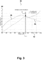
- Fig. 3 shows an exemplary acoustic admittance plot 40 displayed on the display of the new wideband acoustic immittance measurement apparatus 10.
- frequency is plotted along the x-axis 42 and values in mmho of the conductance G(f) and susceptance B(f) are plotted along the y-axis 44.
- the dashed curve 46 shows a plot of the conductance G(f)
- the solid curve 48 shows a plot of the susceptance B(f).
- the admittance Y(f) was determined at ambient pressure p amb .
- one middle ear resonance has been identified and marked by arrow 1 displayed on the display.
- the first frequency f res,1 at which the processor 28 has determined a local or global maximum of the conductance G(f) 46 is also shown.
- the distance between f res,1 and f res,2 was less than 10 Hz and is not shown.
- plots 50, 54 of the acoustic admittance of a Helmholtz resonator are shown in Figs. 4 and 5 .
- Fig. 4 frequency is plotted along the x-axis 42 and values in mmho of the conductance and susceptance of the Helmholtz resonator is plotted along the y-axis 44.
- the dashed curve 46 shows a plot of the conductance
- the solid curve 48 shows a plot of the susceptance .
- the plot 50 shows that at resonance 52, the conductance 46 has a global maximum while the gradient, which has a negative value, of the susceptance 48 has a global minimum.
- One of these features, or the combined features of the acoustic admittance Y(f) of the ear of the human may be used to identify one or more middle ear resonances based on the determined acoustic admittance Y(f), e.g., as plotted in Fig. 3 , or another wideband acoustic admittance .
- Fig. 5 frequency is plotted along the x-axis 42 and values in mmho of the magnitude is plotted along the y-axis 44 and values in degrees of the phase is plotted along the y-axis 64.
- the dashed curve 56 shows a plot of the magnitude
- the solid curve 58 shows a plot of the phase .
- the plot 54 shows that at middle ear resonance 52, the magnitude has a global maximum while the (negative) gradient of the phase has a global minimum.
- One of these features, or the combined features, of the acoustic admittance Y(f) may be used to identify one or more middle ear resonances of the determined acoustic admittance Y(f) or another wideband acoustic admittance .
- Provision of an air tight seal of the ear canal 100 is cumbersome and time consuming and often establishment of the air tight seal requires more than one attempt.
- the new wideband acoustic immittance measurement apparatus 10 requires no baseline compensation for the above-mentioned identification of the one or more middle ear resonances making the identification more simple and accurate.
- the determination the acoustic admittance Y(f), of the ear includes the acoustic admittance Y EC (f) of the ear canal.
- the ear canal is however redundant to the characteristics of the middle and inner ear and therefore it may be desirable to eliminate or reduce the contribution Y EC (f) of the ear canal before identification of a middle ear resonance.
- p ref static pressure
- a primary middle ear resonance frequency is identified based on the baseline compensated acoustic admittance at the frequency at which the baseline compensated susceptance B BC (f, p ref ) is equal to 0 mmho.
- the wideband acoustic immittance measurement apparatus 10 shown in Fig. 2 is also capable of determining wideband acoustic immittance at static pressures p different from ambient pressure p amb .
- the following disclosure relates to a wideband acoustic immittance measurement apparatus 10 that does have the air pump or compressor 36 accommodated in the housing 14 as shown in Fig. 2 .
- the wideband acoustic immittance measurement apparatus 10 disclosed below is configured for identifying middle ear resonances based on baseline compensation in a new and accurate way.
- the processor 28 is adapted for performing wide band acoustic immittance measurements by controlling the air pump or compressor 36 to provide static pressures p spanning a static pressure range, e.g. including ambient pressure p amb , and determining the wideband acoustic immittance , such as the complex acoustic admittance Y(f, p), the complex acoustic impedance Z(f, p), the complex acoustic reflectance ⁇ (f, p), the complex acoustic energy reflectance ER(f, p), the complex acoustic energy absorbance EA(f, p), or any other function that can be determined based on the output audio signal 30 and the input audio signal 26, as a function of frequency f and static pressure p based on the output audio signal 30 and the input audio signal 26 and the provided static pressure p.
- the complex acoustic admittance Y(f, p) the complex acoustic impedance Z(f
- the processor 28 may be adapted for performing the determination of wideband acoustic immittance applying static pressures p through the ear probe, such as static pressures of 0 daPa, TPP, 200 daPa, - 400 daPa, etc.
- the processor 28 is adapted for determining the wideband acoustic admittance Y(f, p).
- Corresponding baseline compensations may be performed for another immittance, such as the acoustic impedance Z(f), the acoustic reflectance ⁇ (f), the acoustic energy reflectance ER(f), the acoustic absorbance A(f), etc.
- another immittance such as the acoustic impedance Z(f), the acoustic reflectance ⁇ (f), the acoustic energy reflectance ER(f), the acoustic absorbance A(f), etc.
- the first static pressure p 1 may be the ambient pressure p amb ; or, the first static pressure p 1 may be the tympanic peak pressure TPP, etc.
- the frequency range of the output audio signal, and thereby the emitted sound may include the frequency range from 200 Hz - 3 kHz.
- the frequency range of the output audio signal, and thereby the emitted sound may include the frequency range from 200 Hz - 4 kHz.
- the processor 28 is further adapted for controlling the display (not shown), e.g. a printer, a display screen, etc., to show a plot of the determined acoustic immittance and/or and/or with one or more identifications of corresponding one or more middle ear resonances.
- the display e.g. a printer, a display screen, etc.
- identification of possible middle ear resonance(s) may be performed in the same way as explained above for the wideband acoustic immittance , but in the criteria for middle ear resonance identification, the wideband acoustic immittance is substituted with the baseline compensated wideband acoustic immittance , p 2 ).
- the dashed curve 66 shows a plot of the baseline compensated conductance G BC (f, Pref1 ), and the solid curve 48 shows determined values of the baseline compensated susceptance B BC (f, p ref1 ).
- one middle ear resonance has been identified and marked by arrow 3 displayed on the display.
- the first frequency f res,1 at which the processor 28 has determined a global maximum of the baseline compensated conductance G BC (f, p ref1 ) 66 is also shown.
- the second frequency f res,2 at which the processor 28 has determined a global minimum of the baseline compensated susceptance B BC (f, p ref1 ) is not indicated.
- the distance between f res,1 and f res,2 was less than 10 Hz and is not shown.
- Fig. 7 shows a plot 70 of baseline compensated conductances G BC (f, p ref1 , p ref2 ) 72, 76 and susceptances B BC (f, p ref1 , p ref2 ) 74, 78.
- the processor 28 controls the air pump to adjust the static pressure in the ear canal 100 to be equal to the tympanic peak pressure TPP and determine conductance G(f, TPP) and susceptance B(f, TPP) as a function of frequency f.
- Fig. 7 frequency is plotted along the x-axis 42 and magnitude in mmho of the baseline compensated conductance
- the upper dashed curve 72 is the baseline compensated conductance G BC1 (f) and the upper solid curve 74 is the baseline compensated susceptance B BC1 (f).
- the lower dashed curve 76 is the baseline compensated conductance G BC2 (f) and the lower solid curve 78 is the baseline compensated susceptance B BC2 (f).
- the middle ear resonances identified by conventional tympanometry namely the frequencies at which the baseline compensated susceptances B BC1 (f) and B BC2 (f) are equal to zero, are marked with arrows 2a and 2b, respectively.
- the large distance along the frequency axis 42 between arrows 2a and 2b illustrates the dependence on reference pressures p ref1 and p ref2 when using conventional baseline compensation.
- the processor 28 has identified one middle ear resonance marked with arrow 3, which is the same for both baseline compensated admittances Y BC1 (f) and Y BC2 (f), i.e. independent of the static pressures p ref1 and p ref2 . i.e. at the arrow 3 both baseline compensated conductances G BC1 (f) and G BC2 (f) have a global maximum and both gradients of the baseline compensated susceptances B BC1 (f) and B BC2 (f) have a global minimum.
- the processor 28 has identified two further middle ear resonances marked with arrows 4 and 5, respectively, that also coincide for the two baseline compensated admittances Y BC1 (f) and Y BC2 (f).
- the processor 28 has identified a primary middle ear resonance 3 at app. 1200 Hz and a secondary middle ear resonance 4 at app. 800 Hz and a third middle ear resonance at app. 600 Hz.
- Fig. 7 illustrates several important advantages of the new wideband acoustic immittance measurement apparatus 10, namely its capability of identifying middle ear resonances independent of the selected reference pressure of the baseline compensation, and its capability of identifying several middle ear resonances for further characterization of the middle ear subjected to the measurements.
- the middle ear resonances of the determined wideband acoustic immittance may be detected using simple peak detection methods and/or polynomial fits.
- the new wideband acoustic immittance measurement apparatus provides robust identification of middle ear resonances that is independent of which reference static pressure p ref1 , p ref2 is used for baseline compensation, if any.
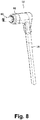
- Fig. 8 shows schematically and in perspective a hand-held ear probe 12 with a probe housing 82 and configured for connection with the new wideband acoustic immittance measurement apparatus 10
- the probe housing 82 accommodates a lamp (not visible) configured to indicate measurement status, such as measurement is in progress, air leakage, instability of the measured ear cavity volume, etc.
- the ear probe 12 is connected with a cable 18 to the new wideband acoustic immittance measurement apparatus 10 in a well-known way.
- the cable 18 includes electrical conductors (not visible) for interconnection of the microphone (not visible) and the loudspeaker (not visible) and the mechanically non-latching switch 86 and lamp (not visible) accommodated in the probe housing 82.
- the cable also 18 has an air conduit (not visible) for interconnection with the pump (not shown) in the housing 14 of the new wideband acoustic immittance measurement apparatus 10 for control of the static pressure in the ear canal 100.
- the ear probe 12 comprises a conventional ear probe tip 80 preferably configured for fitting with an ear tip (not shown) for insertion into the ear canal 100 of the human and for sealing the ear canal 100 with an air tight seal.
- the probe tip 80 is connected with the air conduit of the cable 18 and the pump (not shown) of the new wideband acoustic immittance measurement apparatus 10.
- the ear tip may be disposable and for example made of rubber.
- the results of the ear measurements performed with the new wideband acoustic immittance measurement apparatus 10 with the ear probe 12 are recorded by the new wideband acoustic immittance measurement apparatus 10 and stored in a memory of the wideband acoustic immittance measurement apparatus 10.
- the results are stored together with an indication of whether the right ear or the left ear was subject to the testing as selected with the user interface 32.
Description
- A new wideband acoustic immitance measurement apparatus is provided.
- The middle ear is the portion of the ear internal to the tympanic membrane and external to the oval window of the inner ear. The middle ear comprises the tympanic membrane also denoted the ear drum, and the ossicles, i.e. the malleus, incus and stapes. The ossicles transfer vibrations of the tympanic membrane into waves in the fluid and membranes of the cochlea in the inner ear.
- The primary function of the middle ear is to efficiently transfer acoustic waves in the ear canal incident on the tympanic membrane to fluid-membrane waves within the cochlea. The middle ear efficiency peaks at a frequency of app. 1 kHz. The combined transfer function of the outer ear and middle ear of humans results in peak sensitivity to frequencies between 1 kHz and 3 kHz.
- Tympanometry, sometimes also denoted immittance testing, is a well-known method of examining and diagnosing the middle ear. Tympanometry involves recording changes in middle ear admittance, while static pressure in the ear canal is varied.
- In order to perform tympanometry, an ear probe is inserted in the ear canal in such a way that an air tight seal of the ear canal is provided. The ear probe has a loudspeaker for emission of sound, typically a 226 Hz pure tone, towards the tympanic membrane under varying static pressure in the ear canal inside the seal. The emitted sound causes vibration of the tympanic membrane and the ossicles of the middle ear, which in turn results in the conscious perception of hearing. Some of the emitted sound is reflected and picked up by a microphone of the ear probe. Typically, the ear probe varies the static pressure from - 400 daPa to 200 daPa with 50 - 600 daPa/second sweep pressure rate (1 daPa = 10 Pa).
- The tympanometer determines acoustic admittances of the middle ear based on the microphone signal and plots the determined acoustic admittances as a function of static pressure thereby forming a so-called tympanogram.
- Normally, the static pressure in the ear canal is the same as ambient pressure, and also under normal conditions, the static pressure in the middle ear is approximately the same as ambient pressure since the Eustachian tube opens periodically to ventilate the middle ear and to equalize pressure. In a healthy individual, the maximum sound is transmitted through the middle ear when the static pressure in the ear canal is equal to the pressure in the middle ear also denoted the tympanic peak pressure TPP.
- In multi-frequency tympanometry, the frequency of the pure tone is also varied. With the so-called sweep pressure method, the frequency of the pure tone is held constant while the static pressure is varied; and with the so-called sweep frequency method, the static pressure is held constant at specified intervals while the frequency of the pure tone is varied.
- Experimental data have shown that middle ear pathologies alter tympanometric shapes and shift the resonance frequency of the middle ear. For example, increases in stiffness due to otosclerosis can shift middle ear resonance to a higher than normal frequency, and increases in mass (or lack of stiffness) due to ossicular discontinuity can shift middle ear resonance to a lower than normal frequency.
- In order to perform tympanometry, the ear probe is connected with a cable to a so-called tympanometer, which controls the tympanometry procedure. The measurement results are recorded by the tympanometer.
- The cable typically includes electrical conductors for interconnection of the microphone and a loudspeaker and switches and possible indicators, respectively, of the ear probe.
- The cable also has an air conduit for interconnection with a pump of the tympanometer for control of the static pressure in the ear canal subjected to the tympanometry test.
- A hand-held ear probe may be used for screening purposes, while an ear probe that is retained more securely in or at the ear canal of a human is typically preferred for clinical tests.
- Robert H. Margolis and Hortensia G. Goycoolea: "Multifrequency Tympanometry in Normal Adults", Ear and Hearing 14 (6): 408 - 413, December 1993, discloses recording of multifrequency tympanograms from 56 ears of 28 normal-hearing adult subjects to obtain normative data and to determine abnormal criteria for tympanometric measures. Static admittance, tympanometric width, and tympanometric peak pressure at 226 Hz were analysed along with eight different estimates of the resonant frequency of the middle ear. Based on test-retest reliability and normal distribution characteristics, preferred methods for clinical estimation of resonant frequency were determined. The sweep pressure mode, i.e. ear canal pressure is swept while probe frequency is held constant, is preferred for detection of abnormally high resonant frequencies. The sweep frequency mode, i.e. probe frequency is swept while ear canal air pressure is held constant, is preferred for identification of abnormally low resonant frequencies. Compensation for ear canal volume at +200 daPa was preferred over other compensation methods for estimation of middle ear resonant frequency.
- Dan Lai, Wanrong Li, Junming Xian, and Shixi Liu: "Multifrequency tympanometry in adults with otitis media with effusion", European Archives of Oto-rhino-laryngology, September 2008, Volume 265, Issue 9, 1021 - 1025, published online 14 May 2008, discloses comparison of the diagnostic values of multifrequency tympanometry (MFT) and conventional 226 Hz tympanometry in adults with otitis media with effusion (OME) and discuss whether the resonant frequency (RF) can be used as a reliable method in adults with OME. Prospective study was designed to compare the normal hearing group and the group with OME. In the OME group (n = 85), conductive or mixed hearing loss was found, air-bone gap was more than 10 dBHL, and acoustic reflex was not elicited. In the normal hearing group (n = 36), pure tone threshold was less than or equal to 15 dBHL and air-bone gap was less than 10 dBHL. Levene's test was used to compare the difference between the OME group and the normal hearing group on day1, day15, day30, day90, respectively. The relationship among multifrequency tympanometry, 226-Hz tympanometry and acoustic reflex test in ears recovering from OME was also investigated. A statistically significant decrease in RF value was found in ears with OME compared to normative data. In follow-up visits, both the RF values and the percentage of type A tympanograms increased while the percentage of type B and C tympanograms decreased. A high agreement between middle ear resonant frequency test and acoustic reflex test in ears recovering from OME was found. The resonant frequency test provides more detailed information than the 226-Hz tympanometry. Multifrequency tympanometry may be a more sensitive and objective diagnostic tool in adults with OME.
-
EP 3 053 522 A1 - Utilizing conventional multi-frequency tympanometry to diagnose the middle ear is cumbersome due to the large number of measurements that have to be performed and the resultant abundance of data that has to be collected and interpreted by the audiologist.
- Thus, there is a need for an improved apparatus for accurately characterizing the middle ear based on a reduced number of measurements and providing data that are easy to interpret by the audiologist.
- Further, there is a need for an improved apparatus for accurately characterizing the middle ear in a robust and direct way.
- Thus, a new wideband acoustic immittance measurement apparatus for determination of wideband acoustic immittancein an ear of a human is provided for characterization of the middle ear of the human.

- The new wideband acoustic immittance measurement apparatus is configured for determination of wideband acoustic immittancewith an ear probe inserted in the ear of the human, and for characterizing the middle ear by identifying one or more middle ear resonances, if any, based on the determined wideband acoustic immittance.
- The criteria for identification of a middle ear resonance are based on the realisation that middle ear resonances have characteristics that are similar to the characteristics of the resonance of a Helmholtz resonator, or network of Helmholtz resonators.
- A middle ear resonance may be identified based on a comparison of characteristics of the determined wideband acoustic immitancewith corresponding characteristics at the resonance frequency f0 of the Helmholtz resonator, or one resonance frequency f0 of the network of Helmholtz resonators, of the corresponding wideband acoustic immittancedetermined for the Helmholtz resonator, or network of Helmholtz resonators.

- An overview of wideband acoustic immitance measurements and reviews of the relationships among different acoustic immittance measurements, including acoustic impedance, acoustic admittance, acoustic reflectance, and acoustic absorbance, are provided by: John J. Rosowski, Stefan Stenfelt, and David Lilly: "An Overview of Wideband Immittance Measurements Techniques and Terminology: You Say Absorbance, I Say Reflectance", Ear and Hearing 2013,; 34; 9S-16S.
- With the new wideband acoustic immitance measurement apparatus, acoustic immittance measurements are performed with an ear probe positioned in the ear of the human for emission of sound towards the tympanic membrane at the end of the ear canal.
- Thus, the new wideband acoustic immittance measurement apparatus for determination of wideband acoustic immittancein the ear of the human, comprises an ear probe for insertion in the ear of the human and having
- an acoustic output port for emission of sound into the ear of the human, and
- an acoustic input port for reception of sound in the ear of the human, and
- The ear probe may accommodate one of, or both of, the loudspeaker and the microphone.
- Thus, the new wideband acoustic immittance measurement apparatus for determination of wideband acoustic immittancein the ear of the human, may comprise an ear probe for insertion in an ear canal of the human and having the loudspeaker for conversion of the output audio signal into the sound, and the microphone for generation of the input audio signal as a function of sound pressure at the microphone.
- The new wideband acoustic immittance measurement apparatus may have a housing separate from the ear probe for accommodation of one of, or both of, the loudspeaker and the microphone.
- When operated, the housing is interconnected with the ear probe with a cable that contains electrical wires for interconnection with the microphone and/or the loudspeaker when accommodated in the ear probe and that contains air conduits for acoustic interconnection of the microphone and/or the loudspeaker when accommodated in the housing with the respective acoustic input port and acoustic output port of the ear probe.
- To determine acoustic immittance of the middle ear, the sound delivery system of the wideband acoustic immittance measurement apparatus must be known.
- Calibration of acoustic immittance measurements may be performed as disclosed in:
- Allen, J . B. (1985). Measurement of eardrum acoustic impedance. Peripheral Auditory Mechanism, edited by J . Allen, J. Hall, A. Hubbard, S. Neely, and A.Tubis (Springer-Verlag, New York), and
- Keefe, D. H. (1984). Acoustical wave propagation in cylindrical ducts: transmission line parameter approximation for isothermal and nonisothermal boundary conditions. Journal Acoustical Society of America, (January), and
- Keefe, D. H., Ling, R., & Bulen, J. (1991). Method to measure acoustic impedance and reflection coefficient. Journal Acoustical Society of America, 470-485.
- One example of calibration of wideband acoustic immitance measurements are explained in more detail below with reference to
Fig. 1 ; however, other ways of performing calibration of wideband acoustic immitance measurements are well-known in the art. -
Fig. 1 shows a Thevenin equivalent circuit for an immitance measurement performed with an ear probe. - As shown in
Fig. 1 , the sound source of the ear probe, or connected to the ear probe, is modelled by an ideal sound pressure generator P 0, i.e. a sound pressure generator with zero source impedance, in series with a source impedance Z0, which is connected in series with the acoustic load Z. - The sound pressure P at the acoustic output port of the ear probe is determined by:

- P is the sound pressure measured by the microphone of the ear probe, or connected to the ear probe,
- Z is the acoustic impedance of the acoustic load, e.g. the ear of the human, and
- P 0 and Z 0 are the Thevenin sound source parameters of the ear probe.
- It is implicit that all the quantities are complex functions of frequency f so that equation (1) may be written:

- Measurements of sound pressure P at two different acoustic loads with known acoustic impedances ZA and ZB allow the calculation of the two equivalent circuit parameters of the sound source P 0 and Z 0.
- The parameters of the sound source P 0 and Z 0 are often determined by measurements with more than two cavities, e.g. tubes, with known acoustic impedances Zi :

- Upon calibration of the parameters P 0 and Z 0 of the ear probe, the complex acoustic impedance Z is determined by measuring the sound pressure P with the microphone of the ear probe:

- Based on the determined acoustic impedance Z, other acoustic immittances may be derived, such as:
The complex acoustic admittance Y (typical in units of mmho):
- The complex acoustic reflectance Γ (dimensionless):


- A is the area of the cross-section of the ear canal at the acoustic output port of the ear probe,
- ρ is the density of air, and
- c is the speed of sound.
- The acoustic energy reflectance ER:

- The acoustic energy absorbance:

- It is implicit that all the immittances are complex functionsof the frequency f.
- The wideband acoustic immittancedetermined by the wideband acoustic immittance measurement apparatus, may be any function that can be determined based on measurement with the ear probe, including the acoustic immittances mentioned above, namely acoustic admittance Y(f), acoustic impedance Z(f), acoustic reflectance Γ(f), acoustic energy reflectance ER(f), and acoustic energy absorbance EA(f).
- Thus, the new wideband acoustic immittance measurement apparatus may determine complex acoustic admittance Y(f) = G(f) + j ∗ B(f) = |Y(f)|ejφ(f) with the ear probe positioned in the ear of the human.
- The real part of the acoustic admittance Y(f) is the conductance G(f), and the imaginary part of the acoustic admittance Y(f) is the susceptance B(f).
- |Y(f)| is the magnitude of the acoustic admittance Y(f), in short the acoustic admittance magnitude; and φ(f) is the phase of the acoustic admittance Y(f), in short the acoustic admittance phase.
- The new wideband acoustic immittance measurement apparatus may provide characterization of the middle ear of a human based on the determined complex acoustic admittance Y(f), e.g. based on the conductance G(f) and the susceptance B(f) of the acoustic admittance Y(f); or, based on the acoustic admittance magnitude |Y(f)| and acoustic admittance phase φ(f).
- Correspondingly, the new wideband acoustic immittance measurement apparatus may determine complex acoustic impedance Z(f) = R(f) + j ∗ X(f) = |Z(f)| ejθ(f) with the ear probe positioned in the ear of the human.
- The real part of the acoustic impedance Z(f) is the resistance R(f), and the imaginary part of the acoustic impedance Z(f) is the reactance X(f).
- |Z(f)| is the magnitude of the acoustic impedance Z(f), in short the acoustic impedance magnitude, and θ(f) is the phase of the acoustic impedance Z(f), in short the acoustic impedance phase.
- The new wideband acoustic immittance measurement apparatus may provide characterization of the middle ear of a human based on the determined complex acoustic impedance Z(f), e.g. based on the resistance R(f) and the reactance X(f) of the acoustic impedance Z(f); or, based on the acoustic impedance magnitude |Z(f)| and acoustic impedance phase θ(f).
- The new wideband acoustic immittance measurement apparatus for determination of wideband acoustic immittancein the ear of the human, comprises
a processor that is adapted for - providing an output audio signal to the loudspeaker for conversion into sound for transmission towards a tympanic membrane of the ear and spanning a frequency range, and
- receiving the input audio signal generated by the microphone,
- determining wideband acoustic immittance as a function of frequency f based on the output audio signal and the input audio signal,
- identifying a middle ear resonance based on the determined wideband acoustic immittance at a resonance frequency fres at which an acoustic admittance Y(f) = G(f) + jB(f) corresponding to, or calculated from, the determined wideband acoustic immittancefulfils that the conductance G(fres) is a global or local maximum of the conductance G(f) and that the gradient B'(fres) of the susceptance B(f) is a global or local minimum of the gradient B'(f).
- Throughout the present disclosure, the term "maximum" means a global maximum or a local maximum, and the term "minimum" means a global minimum or a local minimum.
- Preferably, the determined wideband acoustic immittanceis the acoustic admittance Y(f). The criteria for identification of a middle ear resonance are based on the realisation that middle ear resonances have characteristics similar to corresponding characteristics of the resonance of a Helmholtz resonator, or network of Helmholtz resonators.
- At the resonance frequency f0 of a single Helmholtz resonator, the Helmholtz resonator conductanceis a global maximum of the Helmholtz resonator conductance
 (f) as a function of frequency; and the Helmholtz resonator gradient
 is a global minimum of the gradient of the Helmholtz resonator susceptance
 as a function of frequency. Thus, corresponding criteria has been established for identification of a middle ear resonance.
- Equivalently, at the resonance frequency f0 of a single Helmholtz resonator, the Helmholtz resonator acoustic admittance magnitudeis a global maximum of the Helmholtz resonator admittance magnitude
 as a function of frequency; and the Helmholtz resonator phase gradient
 is a global minimum of the Helmholtz resonator phase gradient
 as a function of frequency. Thus, corresponding criteria has been established for identification of a middle ear resonance.
- The immitancemay be represented by the real and imaginary part of the immitance; or, equivalently by the acoustic immittance magnitude and acoustic immittance phase; and other equivalent representations of the acoustic immittancemay be conceived with corresponding equivalent identification criteria for identification of a middle ear resonance.
- The determined wideband acoustic immittancemay be another acoustic immittance than the acoustic admittance Y(f), such as the acoustic impedance Z(f), the acoustic reflectance Γ(f), the acoustic energy reflectance ER (f), the acoustic absorbance A(f), or any other function that can be determined based on the output audio signal and the input audio signal, and criteria for identification of a middle ear resonance corresponding to, or calculated from, the criteria for the acoustic admittance Y(f) may be established based on the relations between the different acoustic immittances, e.g. see equations (5) - (9) above, and/or based on a comparison of the determined wideband acoustic immittancewith the corresponding wideband acoustic immittanceof a Helmholtz resonator, or network of Helmholtz resonators, for identifying one or more middle ear resonances, if any, based on the wideband acoustic immittance, each of which has characteristics of the wideband acoustic immittancesimilar to the characteristics of the corresponding wideband acoustic immittanceof the Helmholtz resonator, or network of Helmholtz resonators, at the resonance of the Helmholtz resonator, or network of Helmholtz resonators.
- The processor may be adapted for identifying a middle ear resonance based on the determined wideband acoustic immittanceat a resonance frequency fres at which an acoustic admittance Y(f) = G(f) + jB(f) corresponding to, or calculated from, the determined wideband acoustic immittancefulfils either that the conductance G(fres) is a global or local maximum of the conductance G(f) or that the gradient B'(fres) of the susceptance B(f) is a global or local minimum of the gradient B'(f) and/or based on a comparison of one part of the determined wideband acoustic immittance, e.g. a real part or a magnitude part or an imaginary part or a phase part or a gradient of one of the parts, etc., with the corresponding part of the wideband acoustic immittanceof a Helmholtz resonator, or network of Helmholtz resonators, for identifying one or more middle ear resonances, if any, based on the wideband acoustic immittance, each of which has characteristics of the wideband acoustic immittancesimilar to the characteristics of the corresponding wideband acoustic immittanceof the Helmholtz resonator, or network of Helmholtz resonators, at the resonance of the Helmholtz resonator, or network of Helmholtz resonators.
- The resonance frequency fres of a middle ear resonance may be determined with some tolerance.
- In the following example, the determined wideband acoustic immittanceis the acoustic admittance Y(f). However, corresponding determinations of a first frequency fres,1 and a second frequency fres,2 may of course be performed for other determined wideband acoustic immittances, such as the acoustic impedance Z(f), the acoustic reflectance Γ(f), the acoustic energy reflectance ER(f), the acoustic absorbance A(f), or any other function that can be determined based on the output audio signal and the input audio signal, and criteria for identification of a middle ear resonance corresponding to, or calculated from, the criteria for the acoustic admittance Y(f) may be established based on the relations between the different acoustic immittances, e.g. see equations (5) - (9) above
- Thus, the processor may be adapted for identifying a resonance of one or more middle ear resonances, if any, by determining a first frequency fres,1 of a maximum, i.e. a local or a global maximum, of, e.g., the conductance G(f) of the determined acoustic admittance Y(f) as a function of frequency f.
- The processor may be adapted for identifying the local or global maximum at the first frequency fres,1 as a middle ear resonance, and fres,1 as the resonance frequency of the middle ear resonance.
- Additionally or alternatively, the processor may be adapted for identifying a resonance of one or more middle ear resonances, if any, by determining a second frequency fres,2 of a local or global minimum of a gradient of, e.g., the susceptance B(f) of the complex acoustic admittance Y(f) as a function of frequency f, and fres,2 as the resonance frequency of the middle ear resonance.
- Further, the processor may be adapted for identifying a resonance of one or more middle ear resonances, by comparing the first frequency fres,1 with the second frequency fres,2, and only if the frequencies fres,1 and fres,2 are identical, or identical apart from measurement inaccuracies and, optionally, some margin, identifying the local or global maximum as a middle ear resonance, i.e. identifying the local or global maximum as a middle ear resonance only when the distance between the first frequency fres,1 and the second frequency fres,2 is less than a threshold value, such as 10 %, such as 5 %, such as 2 %, of the first fres,1 or second frequency fres,2.
- It is an important advantage of the new wideband acoustic immittance measurement apparatus that an air tight seal of the ear canal need not be provided with the ear probe since the determination of the wideband acoustic immittance, e.g. the acoustic admittance Y(f), can take place at ambient pressure. Provision of an air tight seal of the ear canal is cumbersome and time consuming and often the air tight seal is not established in a first attempt. This makes the determination of the wideband acoustic immittancewith the new wideband acoustic immitance measurement apparatus particularly useful for children that often have difficulties avoiding head movements during the determination of wideband acoustic immittance.
- Also, no baseline compensation is required for the above-mentioned identification of the middle ear resonance.
- The new wideband acoustic immittance measurement apparatus may also determine the wideband acoustic immittance, e.g. acoustic admittance Y(f, p), when a static pressure p different from ambient pressure pamb is applied to the ear canal, for identification of one or more middle ear resonances, if any.
- Throughout the present disclosure, a mentioning of a wideband acoustic immittancewithout the static pressure p means that the immittancein question; e.g. the acoustic admittance Y(f), acoustic impedance Z(f), acoustic reflectance Γ(f), acoustic energy reflectance ER(f), acoustic energy absorbance EA(f), or any other function that can be determined based on the output audio signal and the input audio signal, has been determined at ambient pressure pamb.
- Thus, the wideband acoustic immittance measurement apparatus may comprise a housing for accommodation of an air pump or compressor for provision of a static pressure p, and the ear probe may have a static pressure output port and an air conduit connected to the static pressure output port, and the cable interconnecting the housing of the apparatus with the ear probe may comprise an air conduit for interconnection of the air conduit of the ear probe with the air pump or compressor for applying the static pressure p to the ear canal with the ear probe forming an air tight seal with the ear canal wall so that the static pressure p in the ear canal can be controlled utilizing the air pump or compressor.
- The processor may further be adapted for performing wide band acoustic immittance measurements by controlling the air pump to provide static pressures p spanning a static pressure range, and determining the wideband acoustic immittanceas a function of frequency f and static pressure p based on the output audio signal and the input audio signal and the provided static pressure p, such as the complex acoustic admittance Y(f, p), the complex acoustic impedance Z(f, p), the complex acoustic reflectance Γ(f, p), the complex acoustic energy reflectance ER(f, p), the complex acoustic energy absorbance EA(f, p), or any other function that can be determined based on the output audio signal and the input audio signal and the static pressure p.

- The processor may be adapted for identifying a middle ear resonance based on the determined wideband acoustic immittanceat a resonance frequency fres at which an acoustic admittance Y(f, p) = G(f, p) + jB(f, p) corresponding to, or calculated from, the determined wideband acoustic immittancefulfils that the conductance G(fres, p) is a global or local maximum of the conductance G(f, p) and that the gradient B'(fres, p) of the susceptance B(f, p) is a global or local minimum of the gradient B'(f, p). The criteria for identification of a middle ear resonance are based on the realisation that middle ear resonances have characteristics that are similar to the characteristics of the resonance of a Helmholtz resonator, or network of Helmholtz resonators.
- At the resonance frequency f0 of a single Helmholtz resonator, the Helmholtz resonator conductanceis a global maximum of the Helmholtz resonator conductance
 (f) as a function of frequency; and the Helmholtz resonator gradient
 is a global minimum of the gradient of the Helmholtz resonator susceptance
 as a function of frequency. Thus, corresponding criteria has been established for identification of a middle ear resonance.
- Equivalently, at the resonance frequency f0 of a single Helmholtz resonator, the Helmholtz resonator acoustic admittance magnitudeis a global maximum of the Helmholtz resonator admittance magnitude
 as a function of frequency; and the Helmholtz resonator phase gradient
 is a global minimum of the Helmholtz resonator phase gradient
 as a function of frequency. Thus, corresponding criteria has been established for identification of a middle ear resonance.
- The immitance may represented by the real and imaginary part of the immitance; or, equivalently by the acoustic immittance magnitude and acoustic immittance phase; and other equivalent representations of the acoustic immittance may be conceived with corresponding equivalent identification criteria for identification of a middle ear resonance.
- Preferably, the determined wideband acoustic immittanceis the acoustic admittance Y(f, p); however, the determined wideband acoustic immittancemay be another acoustic immittance than the acoustic admittance Y(f, p), such as the acoustic impedance Z(f, p), the acoustic reflectance Γ(f, p), the acoustic energy reflectance ER(f, p), the acoustic absorbance A(f, p), or any other function that can be determined based on the output audio signal and the input audio signal, and criteria for identification of a middle ear resonance corresponding to, or calculated from, the criteria for the acoustic admittance Y(f, p) may be established based on the relations between the different acoustic immittances, e.g. see equations (5) - (9) above, and/or based on a comparison of the determined wideband acoustic immittancewith the corresponding wideband acoustic immittanceof a Helmholtz resonator, or network of Helmholtz resonators, for identifying one or more middle ear resonances, if any, based on the wideband acoustic immittance, each of which has characteristics of the wideband acoustic immittancesimilar to the characteristics of the corresponding wideband acoustic immittanceof the Helmholtz resonator, or network of Helmholtz resonators, at the resonance of the Helmholtz resonator, or network of Helmholtz resonators.
- The processor may be adapted for identifying one or more middle ear resonances, if any, based on the determined wideband acoustic immittanceat a resonance frequency fres at which an acoustic admittance Y(f, p) = G(f, p) + jB(f, p) corresponding to, or calculated from, the determined wideband acoustic immittancefulfils either that the conductance G(fres) is a global or local maximum of the conductance G(f, p) or that the gradient B'(fres) of the susceptance B(f, p) is a global or local minimum of the gradient B'(f, p).
- Alternatively, or additionally, the processor may be adapted for identifying one or more middle ear resonances, if any, based on a comparison of one part of the determined wideband acoustic immittance, e.g. a real part or a magnitude part or an imaginary part or a phase part or a gradient of one of the parts, etc., with the corresponding part of the wideband acoustic immittancedetermined for a Helmholtz resonator, or network of Helmholtz resonators, for identifying one or more middle ear resonances, if any, at respective resonance frequencies fres at which the wideband acoustic immittancehas characteristics similar to the characteristics of the corresponding wideband acoustic immittance
 of the Helmholtz resonator, or network of Helmholtz resonators, at the resonance frequency f0 of the Helmholtz resonator, or at a resonance f0 of the network of Helmholtz resonators.
 - The resonance frequency fres of a middle ear resonance may be determined with some tolerance.
- In the following example, the determined wideband acoustic immittanceis the acoustic admittance Y(f, p). However, corresponding determinations of a first frequency fres,1 and a second frequency fres,2 may of course be performed for other determined wideband acoustic immittances, such as the acoustic impedance Z(f, p), the acoustic reflectance Γ(f, p), the acoustic energy reflectance ER(f, p), the acoustic absorbance A(f, p), or any other function that can be determined based on the output audio signal and the input audio signal, and criteria for identification of a middle ear resonance corresponding to, or calculated from, the criteria for the acoustic admittance Y(f, p) may be established based on the relations between the different acoustic immittances, e.g. see equations (5) - (9) above
- Thus, the processor may be adapted for identifying a resonance of one or more middle ear resonances, if any, by determining a first frequency fres,1 of a maximum, i.e. a local or a global maximum, of, e.g., the conductance G(f, p) of the determined acoustic admittance Y(f, p) as a function of frequency f.
- The processor may be adapted for identifying the local or global maximum at the first frequency fres,1 as a middle ear resonance, and fres,1 as the resonance frequency of the middle ear resonance.
- Additionally or alternatively, the processor may be adapted for identifying a resonance of one or more middle ear resonances, if any, by determining a second frequency fres,2 of a local or global minimum of a gradient of, e.g., the susceptance B(f, p) of the complex acoustic admittance Y(f, p) as a function of frequency f, and fres,2 as the resonance frequency of the middle ear resonance.
- Further, the processor may be adapted for identifying a resonance of one or more middle ear resonances, by comparing the first frequency fres,1 with the second frequency fres,2, and only if the frequencies fres,1 and fres,2 are identical, or identical apart from measurement inaccuracies and, optionally, some margin, identifying the local or global maximum as a middle ear resonance, i.e. identifying the local or global maximum as a middle ear resonance only when the distance between the first frequency fres,1 and the second frequency fres,2 is less than a threshold value, such as 10 %, such as 5 %, such as 2 %, of the first fres,1 or second frequency fres,2.
- The processor may be adapted for performing the determination of wideband acoustic immittanceapplying static pressures p through the ear probe, such as static pressures of 0 daPa, TPP, 200 daPa, - 400 daPa, etc.

- The determination of the wideband acoustic immittance, e.g. the acoustic admittance Y(f), of the ear includes the acoustic immittanceof the ear canal, e.g. the acoustic admittance YEC(f) of the ear canal. The ear canal is however redundant to the characteristics of the middle and inner ear and therefore it may be desirable to eliminate or reduce the contribution of the ear canal from the determined wideband acoustic immittance
 , e.g. acoustic admittance Y(f), before identification of one or more middle ear resonances, if any.
 - In conventional tympanometry, it is recognized that the determination the acoustic admittance Y(f), of the ear includes the acoustic admittance YEC(f) of the ear canal. The ear canal is however redundant to the characteristics of the middle and inner ear and therefore it may be desirable to eliminate or reduce the contribution YEC(f) of the ear canal before identification of a middle ear resonance.
- In conventional tympanometry, the contribution YEC(f) of the ear canal is reduced by subtracting the acoustic admittance YEC(f, pref) measured with a high or low static pressure pref of, e.g. pref1 = 200 daPa or pref2 = - 400 daPa, applied to the ear canal through the ear probe. A high or low static pressure inside the ear canal causes the tympanic membrane to tension and become hard like a wall so that the contribution of the ear canal to the acoustic admittance of the ear is believed to be eliminated or reduced by forming the baseline compensated acoustic admittance:

- In conventional tympanometry, a primary middle ear resonance frequency is identified based on the baseline compensated acoustic admittance at the frequency at which the baseline compensated susceptance BBC(f, pref) is equal to 0 mmho.
- This may not be accurate and may lead to erroneous identification of middle ear resonances.
- Further, the new wideband acoustic immittance measurement apparatus is configured for identifying middle ear resonances based on baseline compensation in a new and accurate way as further explained below, so that the inaccuracy of known baseline compensation has been eliminated or reduced.
- The processor may be adapted for performing baseline compensation, e.g. the processor may be adapted for determining a baseline compensated acoustic admittance YBC(f, p1, p2) = Y1(f, p1) - Y2(f, p2) between a determined acoustic admittance Y1(f, p1) as a function of frequency f at a first static pressure p1 and a determined acoustic admittance Y2(f, p2) as a function of frequency f at a second static pressure p2, and identifying a middle ear resonance, if any, based on the baseline compensated acoustic admittance YBC(f, p1, p2) by determining a first frequency fres,1 and a second frequency fres,2 at which the baseline compensated acoustic admittance YBC(f, p1, p2) = Y1(f, p1) - Y2(f, p2) fulfils that the baseline compensated conductance GBC(fres,1, p1, p2) = G1(fres,1, p1) - G2(fres,1. p2) of the baseline compensated acoustic admittance YBC(f, p1, p2) is a local or global maximum and that the gradient B'(fres,2, p1, p2) of the baseline compensated acoustic susceptance BBC(f, p1, p2) = B1(f, p1) - B2(f, p2) is a local or global minimum and identifying a middle ear resonance when the absolute value of the difference between fres,1 and fres,2 is less than a threshold value determined by measurement inaccuracies and, optionally, some margin, such as 10 %, such as 5 %, such as 2 %, of the first fres,1 or second frequency fres,2.
- Corresponding baseline compensations may be performed for another immittance, such as the acoustic impedance Z(f), the acoustic reflectance Γ(f), the acoustic energy reflectance ER (f), the acoustic absorbance A(f), etc.
- For example, a corresponding baseline compensated acoustic impedance ZBC(f, p1, p2) is given by:

- The first static pressure p1 may be the ambient pressure pamb; or, the first static pressure p1 may be the tympanic peak pressure TPP, etc.
- The second static pressure p2 may be 200 daPa; or, the second static pressure p2 may be - 400 daPa, etc.
- The frequency range of the output audio signal, and thereby the emitted sound, may include the frequency range from 200 Hz - 3 kHz.
- The frequency range of the output audio signal, and thereby the emitted sound, may include the frequency range from 200 Hz - 4 kHz.
- The processor may be adapted for controlling a display, e.g. a printer, a display screen, etc., to show a plot of the determined acoustic immittanceand/orand/orwith one or more identifications of corresponding one or more middle ear resonances.
- Advantageously, the new wideband acoustic immittance measurement apparatus is not dependent on accurate calibration.
- The new wideband acoustic immittance measurement apparatus may be a self-contained unit with its own user interface with switches and a display, possibly a keyboard, as is well-known in the art of immittance measurement apparatuses.
- The new wideband acoustic immittance measurement apparatus may also be based on a general purpose computer, such as a PC, laptop, PDA, smartphone, etc., for recording to the test results and that comprises the user interface of the wideband acoustic immittance measurement apparatus and that is interconnected with and controls a special purpose apparatus with the required measurement circuitry and devices for performing the determination of wideband acoustic immittancein the ear of the human.
- The recorded test results may be stored together with the identification of the right ear or the left ear that the stored test results relate to in the wideband acoustic immittance measurement apparatus and possibly other relevant information, such as the date, time, patient ID, operator ID, etc.
- The recorded data may be transferred to another device, such as a remote storage, such as a server interconnected with the wideband acoustic immittance measurement apparatus through a Wide Area Network, such as the Internet.
- The ear probe may be connected with a cable to the wideband acoustic immittance measurement apparatus in a well-known way.
- The cable may include electrical conductors for interconnection of a microphone and a loudspeaker and switches and possible indicators, respectively, accommodated in the probe housing.
- The cable may also have an air conduit for interconnection with a pump in the wideband acoustic immittance measurement apparatus for control of the static pressure in the ear canal subjected to clinical testing or screening in a way well-known in the art of acoustic immitance measurements.
- The ear probe preferably comprises a conventional ear probe tip that is preferably configured for fitting with an ear tip for insertion into an ear canal of the patient and for sealing the ear canal with an air tight seal.
- The ear probe tip may provide an output of an air conduit connected with the air conduit of the cable to the wideband acoustic immittance measurement apparatus.
- The ear tip may be disposable and for example made of rubber.
- The results of the ear measurements performed with the wideband acoustic immittance measurement apparatus and the ear probe are recorded by the wideband acoustic immittance measurement apparatus and stored in a memory of the wideband acoustic immittance measurement apparatus. The results are stored together with an indication of whether the right ear or the left ear was subject to the testing as selected with the user interface.
- The drawings illustrate the design and utility of embodiments, in which similar elements are referred to by common reference numerals. These drawings may or may not be drawn to scale. In order to better appreciate how the above-recited and other advantages and objects are obtained, a more particular description of the embodiments will be rendered, which are illustrated in the accompanying drawings. These drawings depict only exemplary embodiments and are not therefore to be considered limiting in the scope of the claims.
- In the drawings:
- Fig. 1
- shows a circuit diagram of a Thevenin equivalent circuit for an immitance measurement performed with an ear probe.
- Fig. 2
- schematically illustrates the new wideband acoustic immittance measurement apparatus,
- Fig. 3
- shows an exemplary output plot generated by the new wideband acoustic immittance measurement apparatus and obtained at ambient pressure,
- Fig. 4
- shows plots of the conductance G(f) and susceptance B(f) of a Helmholtz resonator,
- Fig. 5
- shows plots of the magnitude and phase φ(f) of the acoustic admittance
 of a Helmholtz resonator,
- Fig. 6
- shows an exemplary plot of baseline compensated conductance G(f) and susceptance B(f) for a real ear,
- Fig. 7
- shows baseline compensated conductance G(f) and susceptance B(f) recorded at static pressures of + 200 daPa and - 400 daPa, and
- Fig. 8
- schematically shows a perspective view of an ear probe of the wideband acoustic immittance measurement apparatus.
- Various illustrative examples of the new wideband acoustic immittance measurement apparatus according to the appended claims will now be described more fully hereinafter with reference to the accompanying drawings, in which various embodiments of the new wideband acoustic immittance measurement apparatus are illustrated. The new wideband acoustic immittance measurement apparatus according to the appended claims may, however, be embodied in different forms and should not be construed as limited to the embodiments set forth herein. In addition, an illustrated embodiment needs not have all the aspects or advantages shown. An aspect or an advantage described in conjunction with a particular embodiment is not necessarily limited to that embodiment and can be practiced in any other examples even if not so illustrated, or if not so explicitly described.
- It should also be noted that the accompanying drawings are schematic and simplified for clarity, and they merely show details which are essential to the understanding of the new wideband acoustic immittance measurement apparatus, while other details have been left out.
- As used herein, the singular forms "a," "an," and "the" refer to one or more than one, unless the context clearly dictates otherwise.
-
Fig. 2 schematically illustrates one example of the new wideband acousticimmittance measurement apparatus 10 with theear probe 12 positioned with its acoustic output port at or inside anear canal 100 of anear 110 of a human. - The
ear probe 12 of the illustrated wideband acousticimmittance measurement apparatus 10 has an acoustic output port (not visible) for emission of sound towards thetympanic membrane 112 of theear 110 and an acoustic input port (not visible) for reception of sound in theear 110. - A
housing 14 of the wideband acousticimmittance measurement apparatus 10 accommodates aloudspeaker 16 for emission of the sound. Acable 18 interconnects thehousing 14 with theear probe 12 and has anair conduit 20 for transmission of the acoustic sound from theloud speaker 16 in thehousing 14 to the acoustic output port (not visible) of theear probe 12. - The
housing 14 further accommodates amicrophone 22 for generation of aninput audio signal 26 as a function of sound received at the acoustic input port of theear probe 12. Thecable 18 has anair conduit 24 for transmission of the sound received at the acoustic input port of theear probe 12 to themicrophone 22 for conversion into the correspondinginput audio signal 26. - The
housing 14 further accommodates aprocessor 28 that is adapted for controlling theloudspeaker 16 to emit sound spanning a frequency range by generation of anoutput audio signal 30 that is input to theloudspeaker 16 for conversion into the corresponding emitted sound transmitted through theair conduit 20 of thecable 18 and through the acoustic output port (not visible) of theear probe 12 and into theear canal 100 for propagation towards thetympanic membrane 112 at the end of theear canal 100. - The
processor 28 is also connected to the output of themicrophone 22 for reception of theinput audio signal 26 generated by themicrophone 22 in response to sound received at the input port of theear probe 12. - In the wideband acoustic
immittance measurement apparatus 10 shown inFig. 2 , thehousing 14 accommodates both of theloudspeaker 16 and themicrophone 22. Other wideband acoustic immittance measurement apparatuses according to the appended set of claims are provided wherein theear probe 12 accommodates theloudspeaker 16 and themicrophone 22, and wherein theair conduits input audio signal 26 and theoutput audio signal 30, respectively, with the microphone and the loudspeaker in the ear probe. - Yet other wideband acoustic immittance measurement apparatuses according to the appended set of claims are provided wherein the ear probe accommodates one of the
loudspeaker 16 and themicrophone 22, and wherein thecorresponding air conduit input audio signal 26 and theoutput audio signal 30 to the one of theloudspeaker 16 and themicrophone 22. - Optionally, the illustrated wideband acoustic
immittance measurement apparatus 10 has an air pump orcompressor 36 accommodated in thehousing 14 for provision of a static pressure p in theear canal 100. Theprocessor 28 is adapted for controlling the static pressure p provided by the air pump orcompressor 36 withcontrol signal 34. The static pressure p is applied to the ear canal through anair conduit 38 of thecable 18 and through an air conduit (not visible) through theear probe 12. Theear probe 12 seals theear canal 100 with an air tight seal so that the static pressure p in theear canal 100 can be adjusted with the air pump orcompressor 36 as controlled by theprocessor 28. - The
processor 28 is adapted for determining a wideband acoustic immittanceof theear 110 based on theaudio output signal 30 and theinput audio signal 26, optionally at one or more static pressures p. - The
processor 28 is adapted for identifying a middle ear resonance by comparing characteristics of the determined immittancewith the characteristics of a resonance of a Helmholtz resonator, or a network of Helmholtz resonators, of a corresponding immittanceof the Helmholtz resonator, or network of Helmholtz resonators. - The determined wideband acoustic immittancemay be any function that can be determined based on measurement with the ear probe, i.e. based on the
output audio signal 30 and theinput audio signal 26, including the previously mentioned acoustic immittances, namely acoustic admittance Y(f, p), acoustic impedance Z(f, p), acoustic reflectance Γ(f, p), acoustic energy reflectance ER(f, p), and acoustic energy absorbance EA(f, p), including any function that can be determined based on measurement with the ear probe at ambient pressure pamb, i.e. based on theoutput audio signal 30 and theinput audio signal 26 at ambient pressure pamb, including acoustic admittance Y(f), acoustic impedance Z(f), acoustic reflectance Γ(f), acoustic energy reflectance ER(f), and acoustic energy absorbance EA(f). - Throughout the present disclosure, wideband acoustic immittance determined at ambient pressure pamb is writtenomitting the static pressure p, such as acoustic admittance Y(f), acoustic impedance Z(f), acoustic reflectance Γ(f), acoustic energy reflectance ER(f), and acoustic energy absorbance EA(f).
- The
processor 28 is further adapted for identifying one or more middle ear resonances, if any, based on the wideband acoustic immittancedetermined at ambient pressure pamb. - The
processor 28 of the wideband acoustic immitance measurement apparatus shown infig. 2 , is adapted for determining complex acoustic admittance Y(f) = G(f) + j ∗ B(f) = |Y(f)|ejφ(f) with theear probe 12 positioned in theear 110 of the human. - The real part of the acoustic admittance Y(f) is the conductance G(f), and the imaginary part of the acoustic admittance Y(f) is the susceptance B(f).
- |Y(f)| is the magnitude of the acoustic admittance Y(f), in short the acoustic admittance magnitude; and φ(f) is the phase of the acoustic admittance Y(f), in short the acoustic admittance phase.
- The
processor 28 is further adapted for identifying one or more middle ear resonances, if any, based on the determined complex acoustic admittance Y(f), e.g. based on the conductance G(f) and the susceptance B(f) of the acoustic admittance Y(f); or, based on the acoustic admittance magnitude |Y(f)| and acoustic admittance phase φ(f). - Optionally and selectably, the
processor 28 is adapted for determining complex acoustic impedance Z(f) = R(f) + j ∗ X(f) = |Z(f)|ejθ(f) with theear probe 12 positioned in theear 110 of the human. - The real part of the acoustic impedance Z(f) is the resistance R(f), and the imaginary part of the acoustic impedance Z(f) is the reactance X(f).
- |Z(f)| is the magnitude of the acoustic impedance Z(f), in short the acoustic impedance magnitude, and θ(f) is the phase of the acoustic impedance Z(f), in short the acoustic impedance phase.
- Optionally and selectably, the
processor 28 is further adapted for identifying one or more middle ear resonances, if any, based on the determined complex acoustic impedance Z(f), e.g. based on the resistance R(f) and the reactance X(f) of the acoustic impedance Z(f); or, based on the acoustic impedance magnitude |Z(f)| and acoustic impedance phase θ(f). - Optionally and selectably, the processor is adapted for determining another immitance, i.e. any function that can be determined based on measurement with the
ear probe 12 based on theoutput audio signal 30 and theinput audio signal 26, such as acoustic reflectance Γ(f), acoustic energy reflectance ER(f), and acoustic energy absorbance EA(f). - Optionally and selectably, the
processor 28 is further adapted for identifying one or more middle ear resonances, if any, based on the determined other immittance. - At its resonance frequency f0 of a single Helmholtz resonator, the Helmholtz resonator conductanceis a global maximum of the Helmholtz resonator conductance
 as a function of frequency; and the Helmholtz resonator gradient
 is a global minimum of the gradient of the Helmholtz resonator susceptance
 as a function of frequency.
- The
processor 28 is adapted for identifying a possible middle ear resonance of a possible plurality of middle ear resonances by determining a possible first frequency fres,1 of a local or global maximum G(fres,1) of the conductance G(f) of the complex acoustic admittance Y(f) as a function of frequency f. - Further, the
processor 28 is adapted for determining a possible second frequency fres,2 of a local or global minimum of a gradient of the susceptance B(f) of the complex acoustic admittance Y(f) as a function of frequency f. - The
processor 28 is adapted for identifying the possible middle ear resonance of one or more middle ear resonances, by comparing the first frequency fres,1 with the second frequency fres,2, and if the frequencies are identical, or identical apart from measurement inaccuracies and, optionally, some margin, identifying the local or global maximum as a middle ear resonance, e.g. identifying the local or global maximum of the conductance G(fres,1) as a middle ear resonance when the distance between the first frequency fres,1 and the second frequency fres,2 is less than a threshold value, such as 10 %, such as 5 %, such as 2 %, of the first frequency fres,1 or the second frequency fres,2. - Optionally and selectably, the
processor 28 is adapted for identifying the local or global maximum G(fres,1) of the conductance G(f) at the first frequency fres,1 as a middle ear resonance without the comparison. - Optionally and selectably, the
processor 28 is adapted for identifying the local or global minimum B'(fres,2) of the gradient B'(f) of the susceptance B(f) at the second frequency fres,2 as a middle ear resonance without the comparison. - Equivalently, at the resonance frequency f0 of a single Helmholtz resonator, the Helmholtz resonator acoustic admittance magnitudeis a global maximum of the Helmholtz resonator admittance magnitude
 as a function of frequency; and the Helmholtz resonator phase gradient
 is a global minimum of the Helmholtz resonator phase gradient
 as a function of frequency. Thus, corresponding criteria has been established for identification of a middle ear resonance.
- Optionally and selectably, the
processor 28 is adapted for identifying a possible middle ear resonance by determining a first frequency fres,1 of a possible local or global maximum |Y(fes,1)| of the magnitude |Y(f)| of the complex acoustic admittance Y(f) as a function of frequency f. - The
processor 28 is further adapted for determining a second frequency fres,2 where the gradient φ'(f) of the phase φ(f) of the acoustic admittance Y(f) has a local or global minimum φ'(fres,2)· - The
processor 28 is adapted for comparing the first frequency fres,1 with the second frequency fres,2, and if the frequencies are identical, or identical apart from measurement inaccuracies and, optionally, some margin, identifying the local or global maximum of the magnitude |Y(f)| as a middle ear resonance, e.g. identifying the local or global maximum as a middle ear resonance when the distance between the first frequency fres,1 and the second frequency fres,2 is less than a threshold value, such as 10 %, such as 5 %, such as 2 %, of the first frequency. - Optionally and selectably, the
processor 28 may be adapted for identifying the local or global maximum |Y(fres,1)| of the magnitude |Y(f)| at the first frequency fres,1 as a middle ear resonance without the comparison. - Optionally and selectably, the
processor 28 may be adapted for identifying the local or global minimum φ'(fres,2) of the gradient φ'(f) of the phase φ(f) at the second frequency fres,2 as a middle ear resonance without the comparison. - Optionally and selectably, the
processor 28 may be adapted for identifying a possible middle ear resonance of a possible plurality of middle ear resonances based on another determined wideband acoustic immittancethan the admittance Y(f), by calculating the admittance Y(f) based on the determined wideband acoustic immittance, e.g. in accordance with one of the equations (5) - (9) and identifying the possible middle ear resonance(s) as explained above. - Optionally and selectably, the
processor 28 may be adapted for identifying a possible middle ear resonance of a possible plurality of middle ear resonances based on another determined wideband acoustic immittancethan the acoustic admittance Y(f), by calculating criteria for identification of a possible middle ear resonance of a possible plurality of middle ear resonances corresponding to the criteria for the acoustic admittance Y(f) set out above based on the determined wideband acoustic immittance, e.g. in accordance with one of the equations (5) - (9), and identifying the possible middle ear resonance(s) based on the corresponding criteria. - For example, if the determined wideband acoustic immittanceis the acoustic impedance Z(f), the
processor 28 may be adapted for calculating the corresponding acoustic admittance Y(f) in accordance with equation (5) and identify possible middle ear resonances for the corresponding acoustic admittance Y(f) as explained above. Alternatively, or additionally, theprocessor 28 may be adapted for calculating criteria for the acoustic impedance Z(f) that corresponds to the criteria for identification of a possible middle ear resonance of a possible plurality of middle ear resonances set out above for the acoustic admittance Y(f), i.e. in accordance with equation (5) a local or global maximum of the acoustic conductance G(f) corresponds to a local or global minimum of the acoustic resistance R(f) and a local or global minimum of the gradient of the acoustic susceptance B(f) corresponds to a local or global maximum of the gradient of the acoustic reactance X(f); and a local or global maximum of the magnitude |Y(f)| of the acoustic admittance Y(f) corresponds to a minimum of the magnitude |R(f)| of the acoustic impedance Z(f) and a local or global minimum of the gradient φ'(f) of the phase φ(f) of the acoustic admittance Y(f) corresponds to a maximum of the gradient θ'(f) of the phase θ(f) of the acoustic impedance Z(f). - The
processor 28 is connected to auser interface 32 that includes a display (not shown), and theprocessor 28 is adapted for controlling the display to show a plot of the determined acoustic admittance Y(f) on the display including markings, e.g. arrows, of determined middle ear resonances of the acoustic admittance Y(f) and/or YBC(f) and/or Y(f, p). - Optionally and selectably, the
processor 28 is adapted for controlling the display to show plot(s) of one or more other immittances, i.e. any function that can be determined based on measurement with theear probe 12 based on theoutput audio signal 30 and theinput audio signal 26, such as acoustic reflectance Γ(f), acoustic energy reflectance ER(f), and acoustic energy absorbance EA(f), including markings, e.g. arrows, of determined middle ear resonances based on the plotted acoustic immittance. - In the illustrated new wideband acoustic
immittance measurement apparatus 10, theuser interface 32 is accommodated in thehousing 14. In another new wideband acoustic immittance measurement apparatus, the wideband acoustic immittance measurement apparatus is controlled by an external computer (not shown), such as a personal computer, a tablet, a smartphone, etc., and theprocessor 28 is connected to the user interface of the external computer. -
Fig. 3 shows an exemplaryacoustic admittance plot 40 displayed on the display of the new wideband acousticimmittance measurement apparatus 10. InFig. 3 , frequency is plotted along thex-axis 42 and values in mmho of the conductance G(f) and susceptance B(f) are plotted along the y-axis 44. The dashedcurve 46 shows a plot of the conductance G(f), and thesolid curve 48 shows a plot of the susceptance B(f). The admittance Y(f) was determined at ambient pressure pamb. - In the
plot 40, one middle ear resonance has been identified and marked byarrow 1 displayed on the display. The first frequency fres,1 at which theprocessor 28 has determined a local or global maximum of the conductance G(f) 46 is also shown. The distance between fres,1 and fres,2 was less than 10 Hz and is not shown. - In order to illustrate the criteria on which the identification of the middle ear resonance of the
plot 40 shown inFig. 3 is based, plots 50, 54 of the acoustic admittanceof a Helmholtz resonator are shown in
Figs. 4 and5 . - In
Fig. 4 , frequency is plotted along thex-axis 42 and values in mmho of the conductanceand susceptance of the Helmholtz resonator is plotted along the y-
axis 44. The dashedcurve 46 shows a plot of the conductance, and the
solid curve 48 shows a plot of the susceptance.
- The
plot 50 shows that atresonance 52, theconductance 46 has a global maximum while the gradient, which has a negative value, of the
susceptance 48 has a global minimum. One of these features, or the combined features of the acoustic admittance Y(f) of the ear of the human may be used to identify one or more middle ear resonances based on the determined acoustic admittance Y(f), e.g., as plotted in
Fig. 3 , or another wideband acoustic admittance. - In
Fig. 5 , frequency is plotted along thex-axis 42 and values in mmho of the magnitudeis plotted along the y-
axis 44 and values in degrees of the phaseis plotted along the y-
axis 64. The dashedcurve 56 shows a plot of the magnitude, and the
solid curve 58 shows a plot of the phase.
- The
plot 54 shows that atmiddle ear resonance 52, the magnitudehas a global maximum while the (negative) gradient of the phase
 has a global minimum. One of these features, or the combined features, of the acoustic admittance Y(f) may be used to identify one or more middle ear resonances of the determined acoustic admittance Y(f) or another wideband acoustic admittance
 .
. - It is an important advantage of the new wideband acoustic
immittance measurement apparatus 10 that an air tight seal of theear canal 100 need not be provided with theear probe 12 since the determination of the acoustic admittance Y(f), or another wideband acoustic admittance, as a function of frequency f can take place at ambient pressure pamb. - Provision of an air tight seal of the
ear canal 100 is cumbersome and time consuming and often establishment of the air tight seal requires more than one attempt. - This makes the new wideband acoustic
immittance measurement apparatus 10 particularly useful for examination of children that often have difficulties avoiding head movements during the measurement. - Also, the new wideband acoustic
immittance measurement apparatus 10 requires no baseline compensation for the above-mentioned identification of the one or more middle ear resonances making the identification more simple and accurate. - However, determination of wideband acoustic immitance at different static pressures p and baseline compensation may provide useful information on the ear.
- In conventional tympanometry, it is recognized that the determination the acoustic admittance Y(f), of the ear includes the acoustic admittance YEC(f) of the ear canal. The ear canal is however redundant to the characteristics of the middle and inner ear and therefore it may be desirable to eliminate or reduce the contribution YEC(f) of the ear canal before identification of a middle ear resonance.
- In conventional tympanometry, the contribution YEC(f) of the ear canal is reduced by subtracting the acoustic admittance YEC(F, pref) measured with a high or low static pressure pref of, e.g. pref1 = 200 daPa or pref2 = - 400 daPa, applied to the ear canal through the ear probe. A high or low static pressure inside the ear canal causes the tympanic membrane to tension and become hard like a wall so that the contribution of the ear canal to the acoustic admittance of the ear is believed to be eliminated or reduced by forming the baseline compensated acoustic admittance:

- In conventional tympanometry, a primary middle ear resonance frequency is identified based on the baseline compensated acoustic admittance at the frequency at which the baseline compensated susceptance BBC(f, pref) is equal to 0 mmho.
- As mentioned above in connection with
Fig. 2 , optionally, the wideband acousticimmittance measurement apparatus 10 shown inFig. 2 is also capable of determining wideband acoustic immittanceat static pressures p different from ambient pressure pamb. - The following disclosure relates to a wideband acoustic
immittance measurement apparatus 10 that does have the air pump orcompressor 36 accommodated in thehousing 14 as shown inFig. 2 . - Further, the wideband acoustic
immittance measurement apparatus 10 disclosed below, is configured for identifying middle ear resonances based on baseline compensation in a new and accurate way. - The
processor 28 is further adapted for controlling the air pump orcompressor 36 to provide static pressures p spanning a static pressure range including ambient static pressure, e.g. from pref2 = - 400 daPa below ambient pressure to pref1 = 200 daPa above ambient pressure, and determining the wideband acoustic immittance, - e.g. complex acoustic admittance Y(f, p), as a function of frequency f as disclosed above and additionally as a function of static pressure p, based on the input and output audio signals 26, 30 and the provided static pressure p.
- Thus, the
processor 28 is adapted for performing wide band acoustic immittance measurements by controlling the air pump orcompressor 36 to provide static pressures p spanning a static pressure range, e.g. including ambient pressure pamb, and determining the wideband acoustic immittance, such as the complex acoustic admittance Y(f, p), the complex acoustic impedance Z(f, p), the complex acoustic reflectance Γ(f, p), the complex acoustic energy reflectance ER(f, p), the complex acoustic energy absorbance EA(f, p), or any other function that can be determined based on theoutput audio signal 30 and theinput audio signal 26, as a function of frequency f and static pressure p based on theoutput audio signal 30 and theinput audio signal 26 and the provided static pressure p. - The
processor 28 may be adapted for identifying a middle ear resonance based on the determined wideband acoustic immittancein the same way as explained above for wideband acoustic immittancedetermined at ambient pressure pamb, namely by identifying a possible middle ear resonance of possible one or more middle ear resonances based on the determined wideband acoustic immittanceat a resonance frequency fres at which an acoustic admittance Y(f, p) = G(f, p) + jB(f, p) corresponding to, or calculated from, the determined wideband acoustic immittance, fulfils that the conductance G(fres, p) is a global or local maximum of the conductance G(f, p) and that the gradient B'(fres, p) of the susceptance B(f, p) is a global or local minimum of the gradient B'(f, p). - The
processor 28 may be adapted for performing the determination of wideband acoustic immittanceapplying static pressures p through the ear probe, such as static pressures of 0 daPa, TPP, 200 daPa, - 400 daPa, etc. - Preferably, the
processor 28 is adapted for determining the wideband acoustic admittance Y(f, p). - The
processor 28 is adapted for performing baseline compensation, e.g. theprocessor 28 is adapted for determining a baseline compensated acoustic admittance YBC(f, p1, p2) = Y1(f, p1) - Y2(f, p2) between a determined acoustic admittance Y1(f, p1) as a function of frequency f at a first static pressure p1 and a determined acoustic admittance Y2(f, p2) as a function of frequency f at a second static pressure p2, and identifying a middle ear resonance, if any, based on the baseline compensated acoustic admittance YBC(f, p1, p2) by determining a first frequency fres,1 and a second frequency fres,2 at which the baseline compensated acoustic admittance YBC(f, p1, p2) = Y1(f, p1) - Y2(f, p2) fulfils that the baseline compensated conductance GBC(fres,1, p1, p2) = G1(fres,1, p1) - G2(fres,1. p2) of the baseline compensated acoustic admittance YBC(f, p1, p2) is a local or global maximum and that the gradient B'(fres,2, p1, p2) of the baseline compensated acoustic susceptance BBC(f, p1, p2) = B1(f, p1) - B2(f, p2) is a local or global minimum and identifying a middle ear resonance when the absolute value of the difference between fres,1 and fres,2 is less than a threshold value determined by measurement inaccuracies and, optionally, some margin, such as 10 %, such as 5 %, such as 2 %, of the first fres,1 or second frequency fres,2. - Corresponding baseline compensations may be performed for another immittance, such as the acoustic impedance Z(f), the acoustic reflectance Γ(f), the acoustic energy reflectance ER(f), the acoustic absorbance A(f), etc.
- For example, a corresponding baseline compensated acoustic impedance ZBC(f, p1, p2) is given by:

- For example, the first static pressure p1 may be the ambient pressure pamb; or, the first static pressure p1 may be the tympanic peak pressure TPP, etc.
- For example, the second static pressure p2 may be pref1 = 200 daPa; or, the second static pressure p2 may be pref2 = - 400 daPa, etc.
- The frequency range of the output audio signal, and thereby the emitted sound, may include the frequency range from 200 Hz - 3 kHz.
- The frequency range of the output audio signal, and thereby the emitted sound, may include the frequency range from 200 Hz - 4 kHz.
- The
processor 28 is further adapted for controlling the display (not shown), e.g. a printer, a display screen, etc., to show a plot of the determined acoustic immittanceand/orand/orwith one or more identifications of corresponding one or more middle ear resonances.
- Thus for the baseline compensated wideband acoustic immittance, identification of possible middle ear resonance(s) may be performed in the same way as explained above for the wideband acoustic immittance
 , but in the criteria for middle ear resonance identification, the wideband acoustic immittanceis substituted with the baseline compensated wideband acoustic immittance, p2).
-
Fig. 6 shows anexemplary plot 60 of baseline compensated acoustic admittance YBC(f, pref1) = Y(f, pamb) - Y(f, pref1) in which acoustic admittance Y(f, pamb) is determined at ambient pressure pamb and acoustic admittance Y(f, pref1) is determined at a static pressure pref1 = + 200 daPa. - Frequency is plotted along the
x-axis 42 and values in mmho of the baseline compensated conductance GBC(f, pref1) = G(f, pamb) - G(f, pref1) and baseline compensated susceptance BBC(f, pref1) = B(f, pamb)- B(f, pref1) are plotted along the y-axis 44. - The dashed
curve 66 shows a plot of the baseline compensated conductance GBC(f, Pref1), and thesolid curve 48 shows determined values of the baseline compensated susceptance BBC(f, pref1). - In the
plot 60, one middle ear resonance has been identified and marked byarrow 3 displayed on the display. The first frequency fres,1 at which theprocessor 28 has determined a global maximum of the baseline compensated conductance GBC(f, pref1) 66 is also shown. the second frequency fres,2 at which theprocessor 28 has determined a global minimum of the baseline compensated susceptance BBC(f, pref1) is not indicated. The distance between fres,1 and fres,2 was less than 10 Hz and is not shown. - According to conventional tympanometry, a middle ear resonance is determined at a frequency at which the baseline compensated susceptance BBC(f, pref1) = B(f, pamb) - BEC(f, pref1) is equal to zero, which is indicated with
arrow 2 inFig. 6 . - It should be noted that in some cases, one of which is illustrated in
Fig. 6 , the frequency determined by conventional tympanometry is different from the frequency fres,1 at which theprocessor 28 is adapted for identifying a middle ear resonance based on the criteria that the baseline compensated conductance GBC(f, pref1) = G(f, pamb) - G(f, pref1) has a global maximum and that the gradient of the baseline compensated susceptance BBC(f, pref1) = B(f, pamb) - B(f, pref1) has a global minimum, which is indicated witharrow 3 inFig. 6 . -
Fig. 7 shows aplot 70 of baseline compensated conductances GBC(f, pref1, pref2) 72, 76 and susceptances BBC(f, pref1, pref2) 74, 78. - To obtain the
plot 70, theprocessor 28 controls the air pump to adjust the static pressure in theear canal 100 to be equal to the tympanic peak pressure TPP and determine conductance G(f, TPP) and susceptance B(f, TPP) as a function of frequency f. - Then, the
processor 28 controls the air pump to adjust the static pressure p in theear canal 100 to be equal to a reference pressure of pref1 = + 200 daPa and determine conductance G(f, pref1) and susceptance B(f, pref1) as a function of frequency f. - In the
plot 70, the determined acoustic admittance Y(f, pref1) at the referenced pressure pref1 = + 200 daPa is subtracted from the acoustic admittance determined at TPP forming the baseline compensated acoustic admittance YBC(f, TPP, pref1) with reference pressure pref1 = + 200 daPa:


- Further, the
processor 28 controls the air pump to adjust the static pressure p in theear canal 100 to be equal to a reference pressure of pref2 = - 400 daPa and determine conductance G(f, pref2) and susceptance B(f, pref2) as a function of frequency f. - In the
plot 70, the determined acoustic admittance Y(f, pref2) at the reference pressure pref2 = - 400 daPa is subtracted from the acoustic admittance Y(f, TPP) determined at TPP forming the baseline compensated acoustic admittance YBC(f) = Y(f, TPP) - Y(f, pref2) with reference pressure pref2 = - 400 daPa:


- In
Fig. 7 , frequency is plotted along thex-axis 42 and magnitude in mmho of the baseline compensated conductance |GBC(f)| and susceptance |BBC(f)| is plotted along the y-axis 44. The upper dashedcurve 72 is the baseline compensated conductance GBC1(f) and the uppersolid curve 74 is the baseline compensated susceptance BBC1(f). The lower dashedcurve 76 is the baseline compensated conductance GBC2(f) and the lowersolid curve 78 is the baseline compensated susceptance BBC2(f). - The middle ear resonances identified by conventional tympanometry, namely the frequencies at which the baseline compensated susceptances BBC1(f) and BBC2(f) are equal to zero, are marked with
arrows frequency axis 42 betweenarrows - As opposed to this, the
processor 28 has identified one middle ear resonance marked witharrow 3, which is the same for both baseline compensated admittances YBC1(f) and YBC2(f), i.e. independent of the static pressures pref1 and pref2. i.e. at thearrow 3 both baseline compensated conductances GBC1(f) and GBC2(f) have a global maximum and both gradients of the baseline compensated susceptances BBC1(f) and BBC2(f) have a global minimum. - Further, the
processor 28 has identified two further middle ear resonances marked witharrows 4 and 5, respectively, that also coincide for the two baseline compensated admittances YBC1(f) and YBC2(f). - The
processor 28 has identified a primarymiddle ear resonance 3 at app. 1200 Hz and a secondarymiddle ear resonance 4 at app. 800 Hz and a third middle ear resonance at app. 600 Hz. - Thus,
Fig. 7 illustrates several important advantages of the new wideband acousticimmittance measurement apparatus 10, namely its capability of identifying middle ear resonances independent of the selected reference pressure of the baseline compensation, and its capability of identifying several middle ear resonances for further characterization of the middle ear subjected to the measurements. - The middle ear resonances of the determined wideband acoustic immittancemay be detected using simple peak detection methods and/or polynomial fits.
- The new wideband acoustic immittance measurement apparatus provides robust identification of middle ear resonances that is independent of which reference static pressure pref1, pref2 is used for baseline compensation, if any.
-
Fig. 8 shows schematically and in perspective a hand-heldear probe 12 with aprobe housing 82 and configured for connection with the new wideband acousticimmittance measurement apparatus 10 - The
probe housing 82 accommodates a lamp (not visible) configured to indicate measurement status, such as measurement is in progress, air leakage, instability of the measured ear cavity volume, etc. - During testing with the new wideband acoustic
immittance measurement apparatus 10, theear probe 12 is connected with acable 18 to the new wideband acousticimmittance measurement apparatus 10 in a well-known way. Thecable 18 includes electrical conductors (not visible) for interconnection of the microphone (not visible) and the loudspeaker (not visible) and the mechanically non-latching switch 86 and lamp (not visible) accommodated in theprobe housing 82. The cable also 18 has an air conduit (not visible) for interconnection with the pump (not shown) in thehousing 14 of the new wideband acousticimmittance measurement apparatus 10 for control of the static pressure in theear canal 100. - The
ear probe 12 comprises a conventionalear probe tip 80 preferably configured for fitting with an ear tip (not shown) for insertion into theear canal 100 of the human and for sealing theear canal 100 with an air tight seal. Theprobe tip 80 is connected with the air conduit of thecable 18 and the pump (not shown) of the new wideband acousticimmittance measurement apparatus 10. The ear tip may be disposable and for example made of rubber. - The results of the ear measurements performed with the new wideband acoustic
immittance measurement apparatus 10 with theear probe 12 are recorded by the new wideband acousticimmittance measurement apparatus 10 and stored in a memory of the wideband acousticimmittance measurement apparatus 10. The results are stored together with an indication of whether the right ear or the left ear was subject to the testing as selected with theuser interface 32. - Although particular embodiments have been shown and described, it will be understood that it is not intended to limit the claimed inventions to the preferred embodiments, and it will be obvious to those skilled in the art that various changes and modifications may be made without department from the scope of the appended set of claims. The specification and drawings are, accordingly, to be regarded in an illustrative rather than restrictive sense.
a microphone that is arranged for acoustical connection with the acoustic input port of the ear probe for generation of an input audio signal as a function of sound pressure at the acoustic input port.
Claims (13)
- A wideband acoustic immittance measurement apparatus (10) for determination of wideband acoustic immittance in an ear (110) of a human, comprising an ear probe (12) for insertion in the ear (110) of the human and havingan acoustic output port for emission of sound into the ear of the human, andan acoustic input port for reception of sound in the ear of the human, anda loudspeaker (16) that is arranged for acoustical connection with the acoustic output port of the ear probe (12) for emission of the sound, and
a microphone (22) that is arranged for acoustical connection with the acoustic input port of the ear probe (12) for generation of an input audio signal (26) as a function of sound pressure at the acoustic input port, and
a processor (28) that is adapted forproviding an output audio signal (30) to the loudspeaker (16) for conversion into sound spanning a frequency range, andreceiving the input audio signal (26) generated by the microphone (22), determining wideband acoustic immittanceas a function of frequency f based on the output audio signal (30) and the input audio signal (26), characterized in that the processor (28) is further adapted foridentifying a middle ear resonance based on the determined wideband acoustic immittanceat a resonance frequency fres at which an acoustic admittance Y(f) = G(f) + jB(f) corresponding to the determined wideband acoustic immittancefulfils that the conductance G(fres) is a maximum of the conductance G(f) and that the gradient B'(fres) of the susceptance B(f) is a minimum of the gradient B'(f).
 - A wideband acoustic immittance measurement apparatus (10) according to claim 1, wherein the processor (28) is adapted for identifying a middle ear resonance of the determined wideband acoustic immittanceat a resonance frequency fres at which the acoustic admittance Y(f) = G(f) + jB(f) corresponding to the determined wideband acoustic immittancefulfils that the magnitude |Y(fres)| of the acoustic admittance Y(f) is a maximum of the magnitude |Y(f)| and that the gradient φ'(fres) of the phase φ(f) is a minimum of the gradient φ'(f).
- A wideband acoustic immittance measurement apparatus (10) according to claim 1 or 2, wherein the processor (28) is adapted for determining a parameter of the wideband acoustic immittanceat the middle ear resonance of the determined wideband acoustic immittance.
- A wideband acoustic immittance measurement apparatus (10) according to any of the previous claims, wherein the determined wideband acoustic immittanceis selected from the group consisting of:a) Acoustic admittance Y(f) = G(f) + jB(f) = |Y(f)|ejjφ(f) as a function of frequency f,b) acoustic impedance Z(f) = R(f) + j ∗ X(f) = |Z(f)|ejθ(f) as a function of frequency f,c) acoustic reflectance
 d) acoustic absorbance A(f) = 1 - |Γ(f)|2 as a function of frequency f.
 - A wideband acoustic immittance measurement apparatus (10) according to any of the previous claims, wherein the processor (28) is adapted for identifying a plurality of middle ear resonances of the determined wideband acoustic immittanceat a corresponding plurality of resonance frequencies fres,l, wherein at each resonance frequency fres,l the acoustic admittance Y(f) = G(f) + jB(f) corresponding to the determined wideband acoustic immittancefulfils that the conductance G(fres,i) is a maximum of the conductance G(f) and the gradient B'(fres,i) of the susceptance B(f) is a minimum of the gradient B'(f).
- A wideband acoustic immittance measurement apparatus (10) according to any of the previous claims, wherein
the determined wideband acoustic immittanceis the acoustic admittance Y(f) = G(f) + jB(f), and wherein
the processor (28) is adapted for identifying the middle ear resonance at the resonance frequency fres at which the acoustic admittance Y(f) = G(f) + jB(f) fulfils that the conductance G(fres) is a maximum of the conductance G(f) and that the gradient B'(fres) of the susceptance B(f) is a minimum of the gradient B'(f). - A wideband acoustic immittance measurement apparatus (10) according to any of claims 1 - 5, wherein
the determined wideband acoustic immittanceis the acoustic admittance Y(f) = G(f) + jB(f), and wherein
the processor (28) is adapted for identifying the middle ear resonance at the resonance frequency fres at which the acoustic admittance Y(f) = G(f) + jB(f) fulfils that the magnitude |Y(fres)| of the acoustic admittance Y(f) is a maximum of the magnitude |Y(f)| and that the gradient φ'(fres) of the phase φ(f) is a minimum of the gradient φ'(f). - A wideband acoustic immittance measurement apparatus (10) according to any of claims 3 - 7, wherein the parameter of the of the wideband acoustic immittanceat the middle ear resonance is selected from the group consisting of the magnitude of the conductance G(fres), the magnitude of the minimum of the gradient of the susceptance B'(fres).
- A wideband acoustic immittance measurement apparatus (10) according to any of the previous claims, comprising
a housing (14) for accommodation of an air pump, and wherein
the ear probe (12) comprisesan air conduit (38) for connection with the air pump and having an air output for applying a static pressure to the ear canal (100) through an air conduit (38) ofan ear tip for insertion into the ear canal (100) of the human and for sealing the ear canal (100) with an air tight seal, and whereinthe processor (28) is adapted forcontrolling the air pump to provide static pressures p spanning a pressure range, anddetermine the wideband acoustic immittanceas a function of frequency f and static pressure p based on the output audio signal (30) and the input audio signal (26) and the provided static pressure p.
- A wideband acoustic immittance measurement apparatus (10) according to claim 9, wherein
the processor (28) is adapted fordetermining a baseline compensated admittance YBC(f, p1, p2) = Y1(f, P1) - Y2(f, p2) between a determined acoustic admittance Y1(f, p1) as a function of frequency f at a first static pressure p1 and a determined acoustic admittance Y2(f, p2) as a function of frequency f at a second static pressure p2, andidentifying a middle ear resonance based on the baseline compensated acoustic admittance YBC(f, p1, p2) by determining a first frequency fres,1 and a second frequency fres,2 at which the baseline compensated acoustic admittance YBC(f, p1, p2) = Y1(f, p1) - Y2(f, p2) fulfils that the baseline compensated conductance (66, 72, 76) GBC(fres,1, p1, p2) = G1(fres,1, p1)-G2(fres,1. p2) of the baseline compensated acoustic admittance YBC(f, p1, p2) is a local or global maximum and that the gradient B'(fres,2, p1, p2) of the baseline compensated acoustic susceptance (68, 74, 78) BBC(f, p1, p2) = B1(f, p1) - B2(f, p2) is a local or global minimum and identifying a middle ear resonance when the absolute value of the difference between fres,1 and fres,2 is less than a threshold value. - A wideband acoustic immittance measurement apparatus (10) according to any of the previous claims, wherein the frequency range of the output audio signal (30) includes the range from 200 Hz - 4 kHz.
- A wideband acoustic immittance measurement apparatus (10) according to any of the previous claims, wherein the frequency range of the output audio signal (30) includes the range from 200 Hz - 3 kHz.
- A wideband acoustic immittance measurement apparatus (10) according to any of the previous claims, wherein the processor (28) is adapted for controlling a display to show a plot of the determined wideband acoustic immittancewith an indication of the identified middle ear resonance.
Priority Applications (3)
| Application Number | Priority Date | Filing Date | Title |
|---|---|---|---|
| EP17184747.8A EP3437551B1 (en) | 2017-08-03 | 2017-08-03 | Wideband acoustic immittance measurement apparatus |
| US16/045,981 US11076780B2 (en) | 2017-08-03 | 2018-07-26 | Wideband acoustic immittance measurement apparatus |
| US17/305,102 US20210321911A1 (en) | 2017-08-03 | 2021-06-30 | Wideband Acoustic Immittance Measurement Apparatus |
Applications Claiming Priority (1)
| Application Number | Priority Date | Filing Date | Title |
|---|---|---|---|
| EP17184747.8A EP3437551B1 (en) | 2017-08-03 | 2017-08-03 | Wideband acoustic immittance measurement apparatus |
Publications (2)
| Publication Number | Publication Date |
|---|---|
| EP3437551A1 EP3437551A1 (en) | 2019-02-06 |
| EP3437551B1 true EP3437551B1 (en) | 2019-07-31 |
Family
ID=59523010
Family Applications (1)
| Application Number | Title | Priority Date | Filing Date |
|---|---|---|---|
| EP17184747.8A Active EP3437551B1 (en) | 2017-08-03 | 2017-08-03 | Wideband acoustic immittance measurement apparatus |
Country Status (2)
| Country | Link |
|---|---|
| US (2) | US11076780B2 (en) |
| EP (1) | EP3437551B1 (en) |
Families Citing this family (6)
| Publication number | Priority date | Publication date | Assignee | Title |
|---|---|---|---|---|
| US11471074B2 (en) * | 2018-07-30 | 2022-10-18 | The University Of Electro-Communications | Middle ear sound transmission characteristics evaluation system, middle ear sound transmission characteristics evaluation method, and measuring probe |
| CN111227842B (en) * | 2019-12-05 | 2023-03-28 | 北京市医疗器械检验所 | Method for measuring time characteristics of otoacoustic impedance/admittance instrument |
| WO2023019345A2 (en) * | 2021-04-06 | 2023-02-23 | Ecole De Technologie Superieure (Ets) | System, device and method of signal conditioning for earpiece calibration |
| US20230240561A1 (en) * | 2022-01-28 | 2023-08-03 | Father Flanagan's Boys' Home Doing Business As Boys Town National Research Hospital | Systems and methods for the differential diagnosis of middle and inner ear pathologies using wideband acoustic immittance |
| US20230240562A1 (en) * | 2022-01-28 | 2023-08-03 | Father Flanagan's Boy's Home Doing Business as Boys Town National Research Hospital | Systems and methods for estimating hearing loss using wideband acoustic immittance |
| CN115813379B (en) * | 2022-11-16 | 2023-07-04 | 荣耀终端有限公司 | Middle ear sound admittance testing method and device and earphone |
Family Cites Families (26)
| Publication number | Priority date | Publication date | Assignee | Title |
|---|---|---|---|---|
| KR100571811B1 (en) * | 2003-05-09 | 2006-04-17 | 삼성전자주식회사 | Ear type measurement apparatus for bio signal |
| CN101904739B (en) * | 2003-10-09 | 2013-01-16 | 日本电信电话株式会社 | Sphygmomanometer |
| PL1702497T3 (en) * | 2003-12-05 | 2016-04-29 | 3M Innovative Properties Co | Method and apparatus for objective assessment of in-ear device acoustical performance |
| US8652040B2 (en) * | 2006-12-19 | 2014-02-18 | Valencell, Inc. | Telemetric apparatus for health and environmental monitoring |
| US8157730B2 (en) * | 2006-12-19 | 2012-04-17 | Valencell, Inc. | Physiological and environmental monitoring systems and methods |
| JP5789199B2 (en) * | 2009-02-25 | 2015-10-07 | ヴァレンセル,インコーポレイテッド | Headset and earbud |
| CN102481122B (en) * | 2010-06-04 | 2014-10-08 | 松下电器产业株式会社 | Audiometer and method thereof |
| US20130303941A1 (en) * | 2010-12-13 | 2013-11-14 | The Board Of Trustees Of The University Of Illinois | Method and Apparatus for Evaluating Dynamic Middle Ear Muscle Activity |
| CN103460714B (en) * | 2011-01-28 | 2016-08-31 | 海宝拉株式会社 | Ear microphone and ear microphone voltage-operated device |
| EP2928364A4 (en) * | 2013-01-28 | 2015-11-11 | Valencell Inc | Physiological monitoring devices having sensing elements decoupled from body motion |
| US20140288441A1 (en) * | 2013-03-14 | 2014-09-25 | Aliphcom | Sensing physiological characteristics in association with ear-related devices or implements |
| WO2015043677A1 (en) * | 2013-09-30 | 2015-04-02 | Advanced Bionics Ag | System and method for neural cochlea stimulation |
| US9538302B2 (en) * | 2014-01-24 | 2017-01-03 | Genya G Turgul | Detecting headphone earpiece location and orientation based on differential user ear temperature |
| ES2751601T3 (en) * | 2014-02-11 | 2020-04-01 | Med El Elektromedizinische Geraete Gmbh | Determination of amplitude of neuronal action potential based on multi-dimensional differential geometry |
| US9872640B2 (en) * | 2014-03-21 | 2018-01-23 | Mimosa Acoustics, Inc. | Systems, methods, and devices for characterizing ear canal acoustic impedance, admittance, and reflectance by pole-zero fitting |
| US10136843B2 (en) * | 2014-04-23 | 2018-11-27 | Natus Medical Incorporated | Audiologic test apparatus, system and related method |
| EP2966881A1 (en) * | 2014-07-11 | 2016-01-13 | Oticon A/s | Hearing device with ear monitoring function |
| JP6219889B2 (en) * | 2014-09-08 | 2017-10-25 | 京セラ株式会社 | Audio equipment |
| US10441200B2 (en) * | 2015-02-04 | 2019-10-15 | Natus Medical Incorporated | Audiologic test apparatus and method |
| EP3053522A1 (en) * | 2015-02-04 | 2016-08-10 | GN Otometrics A/S | Audiologic test apparatus and method |
| US10542961B2 (en) * | 2015-06-15 | 2020-01-28 | The Research Foundation For The State University Of New York | System and method for infrasonic cardiac monitoring |
| DE102016003133B4 (en) * | 2016-03-15 | 2017-09-28 | Eberhard-Karls-Universität Tübingen | Method for automatically determining an individual function of a DPOAE level map of a human or animal hearing |
| US10258509B2 (en) * | 2016-04-27 | 2019-04-16 | Red Tail Hawk Corporation | In-ear noise dosimetry system |
| US10582328B2 (en) * | 2016-07-06 | 2020-03-03 | Bragi GmbH | Audio response based on user worn microphones to direct or adapt program responses system and method |
| US10803857B2 (en) * | 2017-03-10 | 2020-10-13 | James Jordan Rosenberg | System and method for relative enhancement of vocal utterances in an acoustically cluttered environment |
| US20190038188A1 (en) * | 2017-08-01 | 2019-02-07 | Path Medical Gmbh | Method and apparatus for measuring the Acoustic Reflex with artifact management by using multiple probe tones |
-
2017
- 2017-08-03 EP EP17184747.8A patent/EP3437551B1/en active Active
-
2018
- 2018-07-26 US US16/045,981 patent/US11076780B2/en active Active
-
2021
- 2021-06-30 US US17/305,102 patent/US20210321911A1/en active Pending
Non-Patent Citations (1)
| Title |
|---|
| None * |
Also Published As
| Publication number | Publication date |
|---|---|
| EP3437551A1 (en) | 2019-02-06 |
| US11076780B2 (en) | 2021-08-03 |
| US20190038189A1 (en) | 2019-02-07 |
| US20210321911A1 (en) | 2021-10-21 |
Similar Documents
| Publication | Publication Date | Title |
|---|---|---|
| EP3437551B1 (en) | Wideband acoustic immittance measurement apparatus | |
| Souza et al. | Comparison of nine methods to estimate ear-canal stimulus levels | |
| Lee et al. | Behavioral hearing thresholds between 0.125 and 20 kHz using depth-compensated ear simulator calibration | |
| RU2730425C2 (en) | Microphone calibration compensation by transfer function of connector | |
| Voss et al. | Middle-ear function with tympanic-membrane perforations. I. Measurements and mechanisms | |
| Charaziak et al. | Compensating for ear-canal acoustics when measuring otoacoustic emissions | |
| Shahnaz et al. | Energy reflectance and tympanometry in normal and otosclerotic ears | |
| EP2207366A2 (en) | System to estimate the sound pressure level at eardrum using measurements away from the eardrum | |
| US10441200B2 (en) | Audiologic test apparatus and method | |
| Stepp et al. | Acoustics of the human middle-ear air space | |
| Smull et al. | Evaluation of two circumaural earphones for audiometry | |
| Rogers et al. | Influence of calibration method on distortion-product otoacoustic emission measurements: II. threshold prediction | |
| Withnell et al. | An in situ calibration for hearing thresholds | |
| Voss et al. | How does the sound pressure generated by circumaural, supra-aural, and insert earphones differ for adult and infant ears? | |
| Mason et al. | Comparison of hearing-aid gain using functional, coupler, and probe-tube measurements | |
| O'Brien et al. | Validity and reliability of in-situ air conduction thresholds measured through hearing aids coupled to closed and open instant-fit tips | |
| Barrera-Figueroa | Free-field reciprocity calibration of measurement microphones at frequencies up to 150 kHz | |
| Champlin et al. | Audiometric calibration: Air conduction | |
| Reuven et al. | Effect of calibration method on distortion-product otoacoustic emission measurements at and around 4 kHz | |
| EP4342367A2 (en) | Audiologic test apparatus and method | |
| DK152160B (en) | DEVICE FOR PRESSURE MICROPHONES TO IMPROVE THESE LOW FREQUENCY CHARACTERISTICS | |
| Nørgaard et al. | Reproducing ear-canal reflectance using two measurement techniques in adult ears | |
| LARSON et al. | SOUND LEVELS IN A 2-cc CAVITY, A ZWlSLOCKl COUPLER, AND OCCLUDED EAR CANALS | |
| Sanborn | Predicting hearing aid response in real ears | |
| US20090323989A1 (en) | System and method for calibrating an audiometer signal |
Legal Events
| Date | Code | Title | Description |
|---|---|---|---|
| PUAI | Public reference made under article 153(3) epc to a published international application that has entered the european phase |
Free format text: ORIGINAL CODE: 0009012 |
|
| STAA | Information on the status of an ep patent application or granted ep patent |
Free format text: STATUS: REQUEST FOR EXAMINATION WAS MADE |
|
| 17P | Request for examination filed |
Effective date: 20180405 |
|
| AK | Designated contracting states |
Kind code of ref document: A1 Designated state(s): AL AT BE BG CH CY CZ DE DK EE ES FI FR GB GR HR HU IE IS IT LI LT LU LV MC MK MT NL NO PL PT RO RS SE SI SK SM TR |
|
| AX | Request for extension of the european patent |
Extension state: BA ME |
|
| GRAP | Despatch of communication of intention to grant a patent |
Free format text: ORIGINAL CODE: EPIDOSNIGR1 |
|
| STAA | Information on the status of an ep patent application or granted ep patent |
Free format text: STATUS: GRANT OF PATENT IS INTENDED |
|
| INTG | Intention to grant announced |
Effective date: 20190225 |
|
| GRAS | Grant fee paid |
Free format text: ORIGINAL CODE: EPIDOSNIGR3 |
|
| GRAA | (expected) grant |
Free format text: ORIGINAL CODE: 0009210 |
|
| STAA | Information on the status of an ep patent application or granted ep patent |
Free format text: STATUS: THE PATENT HAS BEEN GRANTED |
|
| AK | Designated contracting states |
Kind code of ref document: B1 Designated state(s): AL AT BE BG CH CY CZ DE DK EE ES FI FR GB GR HR HU IE IS IT LI LT LU LV MC MK MT NL NO PL PT RO RS SE SI SK SM TR |
|
| REG | Reference to a national code |
Ref country code: CH Ref legal event code: EP Ref country code: GB Ref legal event code: FG4D |
|
| REG | Reference to a national code |
Ref country code: DE Ref legal event code: R096 Ref document number: 602017005654 Country of ref document: DE |
|
| REG | Reference to a national code |
Ref country code: AT Ref legal event code: REF Ref document number: 1160054 Country of ref document: AT Kind code of ref document: T Effective date: 20190815 |
|
| REG | Reference to a national code |
Ref country code: IE Ref legal event code: FG4D |
|
| REG | Reference to a national code |
Ref country code: NL Ref legal event code: MP Effective date: 20190731 |
|
| REG | Reference to a national code |
Ref country code: LT Ref legal event code: MG4D |
|
| REG | Reference to a national code |
Ref country code: AT Ref legal event code: MK05 Ref document number: 1160054 Country of ref document: AT Kind code of ref document: T Effective date: 20190731 |
|
| PG25 | Lapsed in a contracting state [announced via postgrant information from national office to epo] |
Ref country code: PT Free format text: LAPSE BECAUSE OF FAILURE TO SUBMIT A TRANSLATION OF THE DESCRIPTION OR TO PAY THE FEE WITHIN THE PRESCRIBED TIME-LIMIT Effective date: 20191202 Ref country code: NO Free format text: LAPSE BECAUSE OF FAILURE TO SUBMIT A TRANSLATION OF THE DESCRIPTION OR TO PAY THE FEE WITHIN THE PRESCRIBED TIME-LIMIT Effective date: 20191031 Ref country code: FI Free format text: LAPSE BECAUSE OF FAILURE TO SUBMIT A TRANSLATION OF THE DESCRIPTION OR TO PAY THE FEE WITHIN THE PRESCRIBED TIME-LIMIT Effective date: 20190731 Ref country code: AT Free format text: LAPSE BECAUSE OF FAILURE TO SUBMIT A TRANSLATION OF THE DESCRIPTION OR TO PAY THE FEE WITHIN THE PRESCRIBED TIME-LIMIT Effective date: 20190731 Ref country code: NL Free format text: LAPSE BECAUSE OF FAILURE TO SUBMIT A TRANSLATION OF THE DESCRIPTION OR TO PAY THE FEE WITHIN THE PRESCRIBED TIME-LIMIT Effective date: 20190731 Ref country code: SE Free format text: LAPSE BECAUSE OF FAILURE TO SUBMIT A TRANSLATION OF THE DESCRIPTION OR TO PAY THE FEE WITHIN THE PRESCRIBED TIME-LIMIT Effective date: 20190731 Ref country code: BG Free format text: LAPSE BECAUSE OF FAILURE TO SUBMIT A TRANSLATION OF THE DESCRIPTION OR TO PAY THE FEE WITHIN THE PRESCRIBED TIME-LIMIT Effective date: 20191031 Ref country code: HR Free format text: LAPSE BECAUSE OF FAILURE TO SUBMIT A TRANSLATION OF THE DESCRIPTION OR TO PAY THE FEE WITHIN THE PRESCRIBED TIME-LIMIT Effective date: 20190731 Ref country code: LT Free format text: LAPSE BECAUSE OF FAILURE TO SUBMIT A TRANSLATION OF THE DESCRIPTION OR TO PAY THE FEE WITHIN THE PRESCRIBED TIME-LIMIT Effective date: 20190731 |
|
| PG25 | Lapsed in a contracting state [announced via postgrant information from national office to epo] |
Ref country code: GR Free format text: LAPSE BECAUSE OF FAILURE TO SUBMIT A TRANSLATION OF THE DESCRIPTION OR TO PAY THE FEE WITHIN THE PRESCRIBED TIME-LIMIT Effective date: 20191101 Ref country code: AL Free format text: LAPSE BECAUSE OF FAILURE TO SUBMIT A TRANSLATION OF THE DESCRIPTION OR TO PAY THE FEE WITHIN THE PRESCRIBED TIME-LIMIT Effective date: 20190731 Ref country code: IS Free format text: LAPSE BECAUSE OF FAILURE TO SUBMIT A TRANSLATION OF THE DESCRIPTION OR TO PAY THE FEE WITHIN THE PRESCRIBED TIME-LIMIT Effective date: 20191130 Ref country code: LV Free format text: LAPSE BECAUSE OF FAILURE TO SUBMIT A TRANSLATION OF THE DESCRIPTION OR TO PAY THE FEE WITHIN THE PRESCRIBED TIME-LIMIT Effective date: 20190731 Ref country code: ES Free format text: LAPSE BECAUSE OF FAILURE TO SUBMIT A TRANSLATION OF THE DESCRIPTION OR TO PAY THE FEE WITHIN THE PRESCRIBED TIME-LIMIT Effective date: 20190731 Ref country code: RS Free format text: LAPSE BECAUSE OF FAILURE TO SUBMIT A TRANSLATION OF THE DESCRIPTION OR TO PAY THE FEE WITHIN THE PRESCRIBED TIME-LIMIT Effective date: 20190731 |
|
| PG25 | Lapsed in a contracting state [announced via postgrant information from national office to epo] |
Ref country code: TR Free format text: LAPSE BECAUSE OF FAILURE TO SUBMIT A TRANSLATION OF THE DESCRIPTION OR TO PAY THE FEE WITHIN THE PRESCRIBED TIME-LIMIT Effective date: 20190731 |
|
| PG25 | Lapsed in a contracting state [announced via postgrant information from national office to epo] |
Ref country code: RO Free format text: LAPSE BECAUSE OF FAILURE TO SUBMIT A TRANSLATION OF THE DESCRIPTION OR TO PAY THE FEE WITHIN THE PRESCRIBED TIME-LIMIT Effective date: 20190731 Ref country code: PL Free format text: LAPSE BECAUSE OF FAILURE TO SUBMIT A TRANSLATION OF THE DESCRIPTION OR TO PAY THE FEE WITHIN THE PRESCRIBED TIME-LIMIT Effective date: 20190731 Ref country code: DK Free format text: LAPSE BECAUSE OF FAILURE TO SUBMIT A TRANSLATION OF THE DESCRIPTION OR TO PAY THE FEE WITHIN THE PRESCRIBED TIME-LIMIT Effective date: 20190731 Ref country code: IT Free format text: LAPSE BECAUSE OF FAILURE TO SUBMIT A TRANSLATION OF THE DESCRIPTION OR TO PAY THE FEE WITHIN THE PRESCRIBED TIME-LIMIT Effective date: 20190731 Ref country code: EE Free format text: LAPSE BECAUSE OF FAILURE TO SUBMIT A TRANSLATION OF THE DESCRIPTION OR TO PAY THE FEE WITHIN THE PRESCRIBED TIME-LIMIT Effective date: 20190731 |
|
| PG25 | Lapsed in a contracting state [announced via postgrant information from national office to epo] |
Ref country code: CZ Free format text: LAPSE BECAUSE OF FAILURE TO SUBMIT A TRANSLATION OF THE DESCRIPTION OR TO PAY THE FEE WITHIN THE PRESCRIBED TIME-LIMIT Effective date: 20190731 Ref country code: SM Free format text: LAPSE BECAUSE OF FAILURE TO SUBMIT A TRANSLATION OF THE DESCRIPTION OR TO PAY THE FEE WITHIN THE PRESCRIBED TIME-LIMIT Effective date: 20190731 Ref country code: IS Free format text: LAPSE BECAUSE OF FAILURE TO SUBMIT A TRANSLATION OF THE DESCRIPTION OR TO PAY THE FEE WITHIN THE PRESCRIBED TIME-LIMIT Effective date: 20200224 Ref country code: SK Free format text: LAPSE BECAUSE OF FAILURE TO SUBMIT A TRANSLATION OF THE DESCRIPTION OR TO PAY THE FEE WITHIN THE PRESCRIBED TIME-LIMIT Effective date: 20190731 Ref country code: LU Free format text: LAPSE BECAUSE OF NON-PAYMENT OF DUE FEES Effective date: 20190803 Ref country code: MC Free format text: LAPSE BECAUSE OF FAILURE TO SUBMIT A TRANSLATION OF THE DESCRIPTION OR TO PAY THE FEE WITHIN THE PRESCRIBED TIME-LIMIT Effective date: 20190731 |
|
| REG | Reference to a national code |
Ref country code: BE Ref legal event code: MM Effective date: 20190831 |
|
| REG | Reference to a national code |
Ref country code: DE Ref legal event code: R097 Ref document number: 602017005654 Country of ref document: DE |
|
| PLBE | No opposition filed within time limit |
Free format text: ORIGINAL CODE: 0009261 |
|
| STAA | Information on the status of an ep patent application or granted ep patent |
Free format text: STATUS: NO OPPOSITION FILED WITHIN TIME LIMIT |
|
| PG2D | Information on lapse in contracting state deleted |
Ref country code: IS |
|
| PG25 | Lapsed in a contracting state [announced via postgrant information from national office to epo] |
Ref country code: IE Free format text: LAPSE BECAUSE OF NON-PAYMENT OF DUE FEES Effective date: 20190803 Ref country code: IS Free format text: LAPSE BECAUSE OF FAILURE TO SUBMIT A TRANSLATION OF THE DESCRIPTION OR TO PAY THE FEE WITHIN THE PRESCRIBED TIME-LIMIT Effective date: 20191030 |
|
| 26N | No opposition filed |
Effective date: 20200603 |
|
| PG25 | Lapsed in a contracting state [announced via postgrant information from national office to epo] |
Ref country code: BE Free format text: LAPSE BECAUSE OF NON-PAYMENT OF DUE FEES Effective date: 20190831 |
|
| REG | Reference to a national code |
Ref country code: CH Ref legal event code: PL |
|
| PG25 | Lapsed in a contracting state [announced via postgrant information from national office to epo] |
Ref country code: CH Free format text: LAPSE BECAUSE OF NON-PAYMENT OF DUE FEES Effective date: 20200831 Ref country code: LI Free format text: LAPSE BECAUSE OF NON-PAYMENT OF DUE FEES Effective date: 20200831 |
|
| PG25 | Lapsed in a contracting state [announced via postgrant information from national office to epo] |
Ref country code: CY Free format text: LAPSE BECAUSE OF FAILURE TO SUBMIT A TRANSLATION OF THE DESCRIPTION OR TO PAY THE FEE WITHIN THE PRESCRIBED TIME-LIMIT Effective date: 20190731 |
|
| PG25 | Lapsed in a contracting state [announced via postgrant information from national office to epo] |
Ref country code: HU Free format text: LAPSE BECAUSE OF FAILURE TO SUBMIT A TRANSLATION OF THE DESCRIPTION OR TO PAY THE FEE WITHIN THE PRESCRIBED TIME-LIMIT; INVALID AB INITIO Effective date: 20170803 Ref country code: MT Free format text: LAPSE BECAUSE OF FAILURE TO SUBMIT A TRANSLATION OF THE DESCRIPTION OR TO PAY THE FEE WITHIN THE PRESCRIBED TIME-LIMIT Effective date: 20190731 |
|
| PG25 | Lapsed in a contracting state [announced via postgrant information from national office to epo] |
Ref country code: SI Free format text: LAPSE BECAUSE OF FAILURE TO SUBMIT A TRANSLATION OF THE DESCRIPTION OR TO PAY THE FEE WITHIN THE PRESCRIBED TIME-LIMIT Effective date: 20190731 |
|
| PG25 | Lapsed in a contracting state [announced via postgrant information from national office to epo] |
Ref country code: MK Free format text: LAPSE BECAUSE OF FAILURE TO SUBMIT A TRANSLATION OF THE DESCRIPTION OR TO PAY THE FEE WITHIN THE PRESCRIBED TIME-LIMIT Effective date: 20190731 |
|
| PGFP | Annual fee paid to national office [announced via postgrant information from national office to epo] |
Ref country code: GB Payment date: 20230710 Year of fee payment: 7 |
|
| PGFP | Annual fee paid to national office [announced via postgrant information from national office to epo] |
Ref country code: FR Payment date: 20230801 Year of fee payment: 7 Ref country code: DE Payment date: 20230821 Year of fee payment: 7 |