EP3428906B1 - Display device for displaying images, in particular pictograms, which can be used to review the displayed image - Google Patents
Display device for displaying images, in particular pictograms, which can be used to review the displayed image Download PDFInfo
- Publication number
- EP3428906B1 EP3428906B1 EP17180797.7A EP17180797A EP3428906B1 EP 3428906 B1 EP3428906 B1 EP 3428906B1 EP 17180797 A EP17180797 A EP 17180797A EP 3428906 B1 EP3428906 B1 EP 3428906B1
- Authority
- EP
- European Patent Office
- Prior art keywords
- image
- display
- display means
- displayed
- stored
- Prior art date
- Legal status (The legal status is an assumption and is not a legal conclusion. Google has not performed a legal analysis and makes no representation as to the accuracy of the status listed.)
- Active
Links
- 238000012552 review Methods 0.000 title description 2
- 238000001514 detection method Methods 0.000 claims description 19
- 230000015654 memory Effects 0.000 claims description 19
- 230000003044 adaptive effect Effects 0.000 claims description 5
- 239000004973 liquid crystal related substance Substances 0.000 claims description 2
- 238000012545 processing Methods 0.000 claims description 2
- 238000012360 testing method Methods 0.000 description 7
- 230000006870 function Effects 0.000 description 3
- 238000004040 coloring Methods 0.000 description 1
- 230000007547 defect Effects 0.000 description 1
- 238000013461 design Methods 0.000 description 1
- 238000011990 functional testing Methods 0.000 description 1
- 230000007257 malfunction Effects 0.000 description 1
- 238000000034 method Methods 0.000 description 1
- 230000003287 optical effect Effects 0.000 description 1
- 239000013589 supplement Substances 0.000 description 1
- 230000000007 visual effect Effects 0.000 description 1
Images
Classifications
-
- G—PHYSICS
- G09—EDUCATION; CRYPTOGRAPHY; DISPLAY; ADVERTISING; SEALS
- G09G—ARRANGEMENTS OR CIRCUITS FOR CONTROL OF INDICATING DEVICES USING STATIC MEANS TO PRESENT VARIABLE INFORMATION
- G09G3/00—Control arrangements or circuits, of interest only in connection with visual indicators other than cathode-ray tubes
- G09G3/006—Electronic inspection or testing of displays and display drivers, e.g. of LED or LCD displays
-
- G—PHYSICS
- G08—SIGNALLING
- G08B—SIGNALLING OR CALLING SYSTEMS; ORDER TELEGRAPHS; ALARM SYSTEMS
- G08B7/00—Signalling systems according to more than one of groups G08B3/00 - G08B6/00; Personal calling systems according to more than one of groups G08B3/00 - G08B6/00
- G08B7/06—Signalling systems according to more than one of groups G08B3/00 - G08B6/00; Personal calling systems according to more than one of groups G08B3/00 - G08B6/00 using electric transmission, e.g. involving audible and visible signalling through the use of sound and light sources
- G08B7/062—Signalling systems according to more than one of groups G08B3/00 - G08B6/00; Personal calling systems according to more than one of groups G08B3/00 - G08B6/00 using electric transmission, e.g. involving audible and visible signalling through the use of sound and light sources indicating emergency exits
-
- G—PHYSICS
- G08—SIGNALLING
- G08B—SIGNALLING OR CALLING SYSTEMS; ORDER TELEGRAPHS; ALARM SYSTEMS
- G08B7/00—Signalling systems according to more than one of groups G08B3/00 - G08B6/00; Personal calling systems according to more than one of groups G08B3/00 - G08B6/00
- G08B7/06—Signalling systems according to more than one of groups G08B3/00 - G08B6/00; Personal calling systems according to more than one of groups G08B3/00 - G08B6/00 using electric transmission, e.g. involving audible and visible signalling through the use of sound and light sources
- G08B7/066—Signalling systems according to more than one of groups G08B3/00 - G08B6/00; Personal calling systems according to more than one of groups G08B3/00 - G08B6/00 using electric transmission, e.g. involving audible and visible signalling through the use of sound and light sources guiding along a path, e.g. evacuation path lighting strip
-
- G—PHYSICS
- G09—EDUCATION; CRYPTOGRAPHY; DISPLAY; ADVERTISING; SEALS
- G09F—DISPLAYING; ADVERTISING; SIGNS; LABELS OR NAME-PLATES; SEALS
- G09F13/00—Illuminated signs; Luminous advertising
- G09F13/04—Signs, boards or panels, illuminated from behind the insignia
- G09F13/0418—Constructional details
- G09F2013/05—Constructional details indicating exit way or orientation
-
- G—PHYSICS
- G09—EDUCATION; CRYPTOGRAPHY; DISPLAY; ADVERTISING; SEALS
- G09G—ARRANGEMENTS OR CIRCUITS FOR CONTROL OF INDICATING DEVICES USING STATIC MEANS TO PRESENT VARIABLE INFORMATION
- G09G2320/00—Control of display operating conditions
- G09G2320/02—Improving the quality of display appearance
- G09G2320/029—Improving the quality of display appearance by monitoring one or more pixels in the display panel, e.g. by monitoring a fixed reference pixel
-
- G—PHYSICS
- G09—EDUCATION; CRYPTOGRAPHY; DISPLAY; ADVERTISING; SEALS
- G09G—ARRANGEMENTS OR CIRCUITS FOR CONTROL OF INDICATING DEVICES USING STATIC MEANS TO PRESENT VARIABLE INFORMATION
- G09G2330/00—Aspects of power supply; Aspects of display protection and defect management
- G09G2330/12—Test circuits or failure detection circuits included in a display system, as permanent part thereof
-
- G—PHYSICS
- G09—EDUCATION; CRYPTOGRAPHY; DISPLAY; ADVERTISING; SEALS
- G09G—ARRANGEMENTS OR CIRCUITS FOR CONTROL OF INDICATING DEVICES USING STATIC MEANS TO PRESENT VARIABLE INFORMATION
- G09G2360/00—Aspects of the architecture of display systems
- G09G2360/14—Detecting light within display terminals, e.g. using a single or a plurality of photosensors
- G09G2360/145—Detecting light within display terminals, e.g. using a single or a plurality of photosensors the light originating from the display screen
-
- G—PHYSICS
- G09—EDUCATION; CRYPTOGRAPHY; DISPLAY; ADVERTISING; SEALS
- G09G—ARRANGEMENTS OR CIRCUITS FOR CONTROL OF INDICATING DEVICES USING STATIC MEANS TO PRESENT VARIABLE INFORMATION
- G09G2360/00—Aspects of the architecture of display systems
- G09G2360/18—Use of a frame buffer in a display terminal, inclusive of the display panel
Definitions
- the present invention relates to a display device for displaying images, in particular pictograms, having the features of the preamble of claim 1
- a display device of the type mentioned at the outset has a detection means and a comparison means.
- the comparison means information about the displayed image detected by the detection means can be compared.
- the current which is necessary in order to generate the displayed image by means of the display means can be detected with the detection means.
- the current consumed by the display means is recorded. This value is compared with a reference value. If the detected current deviates from the reference value, it can be assumed that the display device has a malfunction and does not correctly display the image that should be displayed.
- the one from the document DE 10 2007 510 A1 known device is used to display the image, the image data of which is stored in the image memory. It is not described that a plurality of images can be stored in the image memory, between which a selection can be made in order to then display the selected image with the display means.
- Escape route sign light also referred to as escape sign light
- the escape route signs are stored in the image memories.
- the instruction transmitted from a control unit to the escape route number plate light determines which escape route number is displayed.
- dynamic or adaptive escape route guidance is possible, as described, for example, in the ZVEI leaflet 330013: 2016-5 "Adaptive escape route guidance".
- a dynamic Escape routing or an adaptive escape routing the people who leave the building are guided. As a result, these persons can be guided out of the danger area, away from the danger area and / or past the danger area as quickly as possible.
- Part of the invention is a display device which can be divided into several areas. To guide escape routes, it is possible here to switch direction arrows on and off in addition to a fixed term on a display part in order to signal the viewer a safe route out of the danger zone.
- an indicator light with an electrical image display unit in which the image display unit is a display.
- the indicator light has an image memory for storing image information and a control unit for controlling the display on the basis of the stored image information.
- the indicator light can be part of an emergency lighting.
- escape route license plate light by means of which it can be determined whether the escape route label shows a different escape route label or no escape route label at all according to the instruction or due to an error or defect.
- a visual check of the escape route license plate light is possible, but involves a great deal of effort, since it must be checked for each light whether every possible instruction leads to the desired display of the selected escape route label.
- the invention is therefore based on the problem of one from the DE 10 2007 062 510 A1 to change known display device so that an automatic review of the actually displayed image is possible.
- detection means are provided with which it is possible to obtain information from the displayed image as information about the displayed image in order to recognize which image is displayed and then to automatically check with the comparison means whether the display means the device according to the invention displays the image which the device according to the invention has been instructed to display.
- a display device which can be put into a test state in which a predetermined test image is to be displayed by a screen.
- a detection means detects the screen content and then the detected content is compared with the predetermined test image.
- the test image is preferably a monochrome image, the color of which is detected by a color sensor as the detection means.
- the display device can only be used to test the function of the display device in a test mode.
- a content check during normal operation namely whether the correct image is displayed, is also carried out in the document US 2015/0341631 A1 function test described is not possible.
- a device can make a report about the result of the check.
- the display device can have a reporting means which can be used to report when it is determined by means of the comparison means that the image displayed by the display means does not correspond to the image to be selected according to the instruction, that of the information contained in the instruction, the stored image data, their selection has contained the instruction, or corresponds to the information assigned to this image data.
- the message can be made visible by an optical or acoustic indicator of the display means. It is also possible that the reporting means is connected to an output via which a message about the result of the comparison can be passed on to another device.
- the image memory, the processing means, the comparison means and / or the reporting means can be parts of one or more circuits, including integrated circuits.
- a detection of the displayed image or a part of the displayed image is achieved in that the at least one detection means is a brightness sensor or a color sensor.
- a detection means can detect an identifier of the image displayed by the display means at a specific point of the image or of the display means.
- each image can have a specific brightness value or color value at a point on the display means or image.
- This can result from an individual identifier that the stored images have.
- identifiers which are always contained in the image at the same point in the image.
- several partial identifiers are contained in different places in the images, which when combined result in individual identifications of the images.
- the identifier or part identifier can be part of the design of the image to be shown to a user, for example a pictogram.
- the identifiers or partial identifiers can be incorporated into the image especially for the purpose of individual recognition of the image, without becoming part of the image to be displayed, for example a pictogram.
- a display device can have a plurality of detection means, for example one detection means for each partial identifier.
- a position in an area of the display means for example, which has a specific color and / or brightness value depending on the image, can be used as an identifier or partial identifier.
- the information or information is compared with reference values that are transmitted together with the instruction for the selection of the image or are contained in this instruction or together with the image data of the selected image in Image memory are stored or are contained in this image data.
- the specific location of the display means is covered by a frame which surrounds the display means.
- the at least one detection means is then at least partially arranged between the frame and the display means or at least partially arranged in the frame.
- the cover ensures that the identifiers or partial identifiers provided for the purpose of individual recognition of the image are provided in an area of the display means or of the displayed image that is covered by the frame, and that these are not visible to a viewer of the image and do not disturb the viewer because they are not part of the image that is visible to the viewer.
- the display means of a display device according to the invention can be a flat screen, in particular a liquid crystal screen or an OLED screen.
- the display means can be a safety light of an emergency lighting.
- Such a safety light according to the invention can be an escape route license plate light or an escape sign light.
- the images stored in the image memory can be escape route signs.
- At least one safety light according to the invention can be part of an emergency lighting comprising dynamic or adaptive escape route guidance.
- the emergency lighting can have a control device, the control device being connected to the safety light and via this connection from the control device the instruction for selecting the escape route sign, which is to be read from the image memory and displayed by the display means, can be transmitted to the safety light, to mark the escape route.
- the message about the result of the comparison carried out by the comparison means of the safety light can be transmitted from the safety light to the control device.
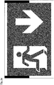
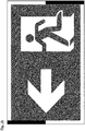
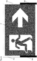
- the ones in the Figures 1a to 1c are typical escape route signs, as they are generally known from many buildings. However, the images differ from conventional images in that they have a border R which surrounds the pictogram P shown in the image of a person fleeing. This edge R is designed as a function of the pictogram P shown. Depending on the pictogram P, areas are provided in the otherwise white border R, which are sometimes black and sometimes white. On the basis of the arrangement of the optionally black or white areas R1 to R4 in the edge R, one can distinguish between the images without having to look at the pictograms P for this purpose. In the three examples, the areas R1 to R4 of the edge R provided for recognizing the images are provided on the narrow sides of the rectangular images. Based on Figures 1a to 1c four areas R1 to R4 can be distinguished, which are sometimes black and sometimes white to distinguish between the images.
- the white or black coloring of the images in the four areas R1 to R4 form partial identifiers, which together form an identifier provided in the image by means of which the image can be recognized.
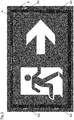
- the partial identifiers can be detected by detection means, namely brightness sensors S1 to S4, which are located in the frame F according to the arrangement Fig. 2 are provided.
- This frame F encloses the display means A and also covers the edge of the display means A.
- the cover of the edge of the display means A by the frame F goes so far that the edge R of the image 1c shown by the display means A is covered by the frame F.
- the brightness sensors S1 to S4 are arranged in frame F in such a way that they lie above the partial identifiers of the displayed image.
- the complete identifier of the image can then be put together from the partial identifiers recognized by the brightness sensors S1 to S4.
- Information about which image is displayed by the display means A can thus be obtained by means of the detection means.
- This information can then be compared by means of a comparison means with information which indicates which image is to be displayed. If both information match, the correct picture is displayed. If, on the other hand, the two pieces of information differ, the wrong image is displayed, the display of the correct image is incorrect and / or the display means A has failed or is disrupted. In either case, the correct image is not presented as it should be presented. There is then an error that can be reported.
Landscapes
- Physics & Mathematics (AREA)
- General Physics & Mathematics (AREA)
- Engineering & Computer Science (AREA)
- Computer Hardware Design (AREA)
- Theoretical Computer Science (AREA)
- Business, Economics & Management (AREA)
- Emergency Management (AREA)
- Controls And Circuits For Display Device (AREA)
Description
Die vorliegende Erfindung betrifft eine Anzeigevorrichtung zur Anzeige von Bildern, insbesondere Piktogrammen, mit den Merkmalen des Oberbegriffs des Anspruchs 1The present invention relates to a display device for displaying images, in particular pictograms, having the features of the preamble of claim 1
Das Dokument
Aus dem Dokument
Durch die Erfassung des Stroms allein, wie auch in dem Dokument
Aber auch die Verwendung der Zusatzmuster führt letztlich nicht dazu, dass sichergestellt ist, dass tatsächlich das anzuzeigende Bild dem angezeigten Bild entspricht. Die Stromaufnahme des Anzeigemittels könnte nämlich auch aus anderen Gründen, die nichts mit dem anzuzeigenden Bild oder dem angezeigten Bild zu tun haben, von dem Referenzwert abweichen.But even the use of the additional pattern does not ultimately lead to a guarantee that the image to be displayed actually corresponds to the displayed image. This is because the power consumption of the display means could also deviate from the reference value for other reasons that have nothing to do with the image to be displayed or the image displayed.
Die aus dem Dokument
Anzeigevorrichtungen bei denen mehrere Bilder in einem Bildspeicher abgelegt sind, von denen dann eines ausgewählt werden kann, um dieses darzustellen, werden in Notbeleuchtungen von Gebäuden als Rettungswegkennzeichenleuchte (auch als Rettungszeichenleuchte bezeichnet) zur Anzeige von Rettungswegkennzeichen eingesetzt. Die Rettungswegkennzeichen sind in den Bildspeichern abgelegt. Durch die von einem Steuergerät zur Rettungswegkennzeichenleuchte übertragene Anweisung wird bestimmt, welches Rettungswegkennzeichen angezeigt wird. Mit dieser Art Rettungswegkennzeichenleuchte ist eine dynamische oder adaptive Fluchtweglenkung möglich, wie sie zum Beispiel in dem ZVEI Merkblatt 330013:2016-5 "Adaptive Fluchtweglenkung" beschrieben ist. In Abhängigkeit von der konkreten Lage in einem Fall in dem ein Gebäude evakuiert werden muss, können durch eine dynamische Fluchtweglenkung oder eine adaptive Fluchtweglenkung die Personen, die das Gebäude verlassen, geleitet werden. Dadurch können diese Personen möglichst schnell aus dem Gefahrenbereich heraus, von dem Gefahrenbereich weg und/oder an dem Gefahrenbereich vorbeigeführt werden.Display devices in which several images are stored in an image memory, one of which can then be selected in order to display it, are used in emergency lighting of buildings as escape route sign light (also referred to as escape sign light) to display escape route signs. The escape route signs are stored in the image memories. The instruction transmitted from a control unit to the escape route number plate light determines which escape route number is displayed. With this type of escape route license plate light, dynamic or adaptive escape route guidance is possible, as described, for example, in the ZVEI leaflet 330013: 2016-5 "Adaptive escape route guidance". Depending on the specific situation in a case in which a building has to be evacuated, a dynamic Escape routing or an adaptive escape routing the people who leave the building are guided. As a result, these persons can be guided out of the danger area, away from the danger area and / or past the danger area as quickly as possible.
Aus der
Aus dem Dokument
Bisher ist nicht bekannt, dass bei einer Rettungswegkennzeichenleuchte eine automatische Überprüfung möglich ist, mittels der festgestellt werden kann, ob das Rettungswegkennzeichen gemäß der Anweisung oder aufgrund eines Fehlers oder Defektes ein anderes oder gar kein Rettungswegkennzeichen anzeigt. Eine visuelle Überprüfung der Rettungswegkennzeichenleuchte ist zwar möglich, aber mit einem sehr hohen Aufwand verbunden, da bei jeder Leuchte geprüft werden muss, ob jede mögliche Anweisung zu der gewünschten Anzeige des ausgewählten Rettungswegkennzeichens führt.So far it is not known that an automatic check is possible with an escape route license plate light, by means of which it can be determined whether the escape route label shows a different escape route label or no escape route label at all according to the instruction or due to an error or defect. A visual check of the escape route license plate light is possible, but involves a great deal of effort, since it must be checked for each light whether every possible instruction leads to the desired display of the selected escape route label.
Die in den Dokumenten
Ähnliche Probleme können bei anderen Anwendungen von Anzeigevorrichtungen der eingangs genannten Art entstehen.Similar problems can arise in other applications of display devices of the type mentioned at the beginning.
Der Erfindung liegt daher das Problem zugrunde, eine aus dem
Dieses Problem wurde erfindungsgemäß durch eine Anzeigevorrichtung nach Anspruch 1 gelöst.According to the invention, this problem has been solved by a display device according to claim 1.
In einer erfindungsgemäßen Anzeigevorrichtung sind also Erfassungsmittel vorgesehen, mit denen es möglich ist, als Information über das angezeigte Bild eine Information aus dem angezeigten Bild zu gewinnen, um zu erkennen welches Bild angezeigt ist und um dann mit dem Vergleichsmittel automatisch zu überprüfen, ob das Anzeigemittel der erfindungsgemäßen Vorrichtung das Bild anzeigt, zu dessen Anzeige die erfindungsgemäße Vorrichtung angewiesen worden ist.In a display device according to the invention, detection means are provided with which it is possible to obtain information from the displayed image as information about the displayed image in order to recognize which image is displayed and then to automatically check with the comparison means whether the display means the device according to the invention displays the image which the device according to the invention has been instructed to display.
Aus dem Dokument
Mit der Anzeigevorrichtung ist lediglich eine Funktionsprüfung der Anzeigevorrichtung in einem Testmodus möglich. Eine Inhaltskontrolle im laufenden Normalbetrieb, nämlich ob das richtige Bild dargestellt wird, ist auch mit der in dem Dokument
Über das Ergebnis der Überprüfung kann eine erfindungsgemäße Vorrichtung eine Meldung machen. Dazu kann die Anzeigevorrichtung ein Meldemittel aufweisen, mit dem gemeldet werden kann, wenn mittels des Vergleichsmittels festgestellt wird, dass das von dem Anzeigemittel angezeigte Bild nicht dem gemäß der Anweisung auszuwählenden Bild, der der in der Anweisung enthaltenen Information, den gespeicherten Bilddaten, deren Auswahl die Anweisung enthalten hat, oder der diesen Bilddaten zugeordneten Information entspricht. Die Meldung kann von einem optischen oder akustischen Melder des Anzeigemittels sichtbar gemacht werden. Ebenso ist es möglich, dass das Meldemittel mit einem Ausgang verbunden ist, über welchen eine Meldung über das Ergebnis des Vergleiches an eine andere Vorrichtung weitergegeben werden kann.A device according to the invention can make a report about the result of the check. For this purpose, the display device can have a reporting means which can be used to report when it is determined by means of the comparison means that the image displayed by the display means does not correspond to the image to be selected according to the instruction, that of the information contained in the instruction, the stored image data, their selection has contained the instruction, or corresponds to the information assigned to this image data. The message can be made visible by an optical or acoustic indicator of the display means. It is also possible that the reporting means is connected to an output via which a message about the result of the comparison can be passed on to another device.
Der Bildspeicher, das Verarbeitungsmittel, das Vergleichsmittel und/oder das Meldemittel können Teile einer oder mehrerer Schaltungen, auch integrierter Schaltungen sein.The image memory, the processing means, the comparison means and / or the reporting means can be parts of one or more circuits, including integrated circuits.
Grundsätzlich sind verschiedene Ausführungen der Erfindung möglich, die auf unterschiedlichen Prinzipien der Erfassung des angezeigten Bildes beruhen. Erfindungsgemäß ist vorgesehen, das angezeigte Bild oder Teile des angezeigten Bildes zu erfassen.In principle, different embodiments of the invention are possible which are based on different principles for capturing the displayed image. According to the invention it is provided that the displayed image or parts of the displayed image are recorded.
Eine Erfassung des angezeigten Bildes oder eines Teils des angezeigten Bildes wird dadurch erreicht, dass das wenigstens eine Erfassungsmittel ein Helligkeitssensor oder ein Farbsensor ist. Ein solches Erfassungsmittel kann eine Kennung des vom Anzeigemittel angezeigten Bildes an einer bestimmten Stelle des Bildes oder des Anzeigemittels erfassen.A detection of the displayed image or a part of the displayed image is achieved in that the at least one detection means is a brightness sensor or a color sensor. Such a detection means can detect an identifier of the image displayed by the display means at a specific point of the image or of the display means.
Dieser Vorgehensweise liegt die Überlegung zu Grunde, dass jedes Bild an einer Stelle des Anzeigemittels oder Bildes einen spezifischen Helligkeitswert oder Farbwert haben kann. Dieser kann sich aufgrund einer individuellen Kennung ergeben, die die abgespeicherten Bilder haben. So ist es zum Beispiel möglich und für die Zwecke der Erfindung so vorgsehen, unterschiedliche angezeigte Bilder durch Kennungen zu unterscheiden, die stets an der gleichen Stelle des Bildes im Bild enthalten sind. Es könnte auch sein, dass mehrere Teilkennungen an verschiedenen Stellen in den Bilder enthalten sind, die in der Kombination individuelle Kennungen der Bilder ergeben. Die Kennung oder Teilkennung kann Teil der einem Benutzer zu zeigenden Gestaltung des Bildes, zum Beispiel eines Piktogramms sein. Es ist aber auch möglich, dass die Kennungen oder Teilkennungen extra zum Zwecke der individuellen Erkennung des Bildes in das Bild eingearbeitet werden, ohne dass sie Teil des anzuzeigenden Bildes, zum Beispiel Piktogramms werden.This procedure is based on the consideration that each image can have a specific brightness value or color value at a point on the display means or image. This can result from an individual identifier that the stored images have. For example, it is possible, and for the purposes of the invention, to distinguish between different displayed images by means of identifiers which are always contained in the image at the same point in the image. It could also be that several partial identifiers are contained in different places in the images, which when combined result in individual identifications of the images. The identifier or part identifier can be part of the design of the image to be shown to a user, for example a pictogram. However, it is also possible for the identifiers or partial identifiers to be incorporated into the image especially for the purpose of individual recognition of the image, without becoming part of the image to be displayed, for example a pictogram.
Damit jede dieser Teilkennungen erfasst werden kann, kann eine erfindungsgemäße Anzeigevorrichtung mehrere Erfassungsmittel aufweisen, zum Beispiel für jede Teilkennung ein Erfassungsmittel.So that each of these partial identifiers can be detected, a display device according to the invention can have a plurality of detection means, for example one detection means for each partial identifier.
Als Kennung oder Teilkennung kommt zum Beispiel eine Stelle in einem Bereich des Anzeigemittels in Frage, die je nach Bild einen bestimmten Farb- und/oder Helligkeitswert hat.A position in an area of the display means, for example, which has a specific color and / or brightness value depending on the image, can be used as an identifier or partial identifier.
Zur Erkennung des Bildes aus der oder den erfassten Informationen wird die erfasste Information oder werden die erfassten Informationen mit Referenzwerten verglichen, die zusammen mit der Anweisung für die Auswahl des Bildes übertragen werden oder in dieser Anweisung enthalten sind oder zusammen mit den Bilddaten des ausgewählten Bildes im Bildspeicher abgelegt sind oder in diesen Bilddaten enthalten sind.To recognize the image from the information or information recorded, the information or information is compared with reference values that are transmitted together with the instruction for the selection of the image or are contained in this instruction or together with the image data of the selected image in Image memory are stored or are contained in this image data.
Die bestimmte Stelle des Anzeigemittels ist von einem Rahmen, der das Anzeigemittel einfasst, abgedeckt. Dann ist das wenigstens eine Erfassungsmittel zumindest teilweise zwischen dem Rahmen und dem Anzeigemittel angeordnet oder zumindest teilweise in dem Rahmen angeordnet.The specific location of the display means is covered by a frame which surrounds the display means. The at least one detection means is then at least partially arranged between the frame and the display means or at least partially arranged in the frame.
Durch die Abdeckung wird erreicht, dass die zum Zwecke der individuellen Erkennung des Bildes vorgesehenen Kennungen oder Teilkennungen in einem vom Rahmen abgedeckten Bereich des Anzeigemittels bzw. des angezeigten Bildes vorgesehen sind, und diese für einen Betrachter des Bildes nicht sichtbar sind und den Betrachter nicht stören, da sie nicht Teil des für den Betrachter sichtbaren Bildes sind.The cover ensures that the identifiers or partial identifiers provided for the purpose of individual recognition of the image are provided in an area of the display means or of the displayed image that is covered by the frame, and that these are not visible to a viewer of the image and do not disturb the viewer because they are not part of the image that is visible to the viewer.
Das Anzeigemittel einer erfindungsgemäßen Anzeigevorrichtung kann ein Flachbildschirm, insbesondere Flüssigkristallbildschirm oder ein OLED-Bildschirm sein.The display means of a display device according to the invention can be a flat screen, in particular a liquid crystal screen or an OLED screen.
Das Anzeigemittel kann eine Sicherheitsleuchte einer Notbeleuchtung sein.The display means can be a safety light of an emergency lighting.
Eine solche erfindungsgemäße Sicherheitsleuchte kann eine Rettungswegkennzeichenleuchte oder Rettungszeichenleuchte sein.Such a safety light according to the invention can be an escape route license plate light or an escape sign light.
Die im Bildspeicher gespeicherten Bilder können Rettungswegkennzeichen sein.The images stored in the image memory can be escape route signs.
Mindestens eine erfindungsgemäße Sicherheitsleuchte kann Teil einer Notbeleuchtung umfassend eine dynamische oder adaptive Fluchtweglenkung sein. Die Notbeleuchtung kann neben der Sicherheitsleuchte ein Steuergerät aufweisen, wobei das Steuergerät mit der Sicherheitsleuchte verbunden ist und über diese Verbindung von dem Steuergerät die Anweisung zur Auswahl des Rettungswegkennzeichens, welches aus dem Bildspeicher auszulesen und durch das Anzeigemittel anzuzeigen ist, an die Sicherheitsleuchte übertragbar ist, um den Rettungsweg zu kennzeichnen.At least one safety light according to the invention can be part of an emergency lighting comprising dynamic or adaptive escape route guidance. In addition to the safety light, the emergency lighting can have a control device, the control device being connected to the safety light and via this connection from the control device the instruction for selecting the escape route sign, which is to be read from the image memory and displayed by the display means, can be transmitted to the safety light, to mark the escape route.
Über die Verbindung zwischen dem Steuergerät und der Sicherheitsleuchte kann von der Sicherheitsleuchte die Meldung über das Ergebnis des von dem Vergleichsmittel der Sicherheitsleuchte durchgeführten Vergleiches zum Steuergerät übertragen werden.Via the connection between the control device and the safety light, the message about the result of the comparison carried out by the comparison means of the safety light can be transmitted from the safety light to the control device.
Weitere Merkmale und Vorteile der vorliegenden Erfindung werden anhand der Zeichnung eines Ausführungsbeispiels beschrieben. Darin zeigen:
- Fig. 1a bis 1c
- Darstellungen von Bildern die mit einem Anzeigemittel einer erfindungsgemäßen Anzeigevorrichtung angezeigt werden können.
- Fig. 2
- eine Draufsicht auf eine Anordnung aus einem ein Bild anzeigendes Anzeigemittels und eines Rahmens, in dem Erfassungsmittel angeordnet sind.
- Figures 1a to 1c
- Representations of images that can be displayed with a display means of a display device according to the invention.
- Fig. 2
- a plan view of an arrangement of a display means displaying an image and a frame in which detection means are arranged.
Die in den
Die weiße oder schwarze Färbung der Bilder in den vier Bereichen R1 bis R4 bilden Teilkennungen, die zusammen eine in dem Bild vorgesehene Kennung bilden, anhand der das Bild erkannt werden kann.The white or black coloring of the images in the four areas R1 to R4 form partial identifiers, which together form an identifier provided in the image by means of which the image can be recognized.
Die Teilkennungen können von Erfassungsmitteln, nämlich Helligkeitssensoren S1 bis S4 erfasst werden, die in dem Rahmen F der Anordnung nach
Aus den durch die Helligkeitssensoren S1 bis S4 erkannten Teilkennungen kann dann die vollständige Kennung des Bildes zusammengesetzt werden. Damit kann mittels der Erfassungsmittel eine Information gewonnen werden, welches Bild von dem Anzeigemittel A angezeigt wird. Diese Information kann dann mittels eines Vergleichsmittels mit einer Information verglichen werden, die angibt, welches Bild angezeigt werden soll. Stimmen beide Informationen überein, wird das richtige Bild dargestellt. Unterscheiden sich die beiden Informationen dagegen, wird das falsche Bild dargestellt, ist die Darstellung des richtigen Bildes fehlerhaft und/oder das Anzeigemittel A ausgefallen oder gestört. In jedem Fall ist das richtige Bild nicht so dargestellt, wie es dargestellt werden soll. Es liegt dann ein Fehler vor, der gemeldet werden kann.The complete identifier of the image can then be put together from the partial identifiers recognized by the brightness sensors S1 to S4. Information about which image is displayed by the display means A can thus be obtained by means of the detection means. This information can then be compared by means of a comparison means with information which indicates which image is to be displayed. If both information match, the correct picture is displayed. If, on the other hand, the two pieces of information differ, the wrong image is displayed, the display of the correct image is incorrect and / or the display means A has failed or is disrupted. In either case, the correct image is not presented as it should be presented. There is then an error that can be reported.
Claims (8)
- Display device for displaying images, in particular pictograms,- having an image memory, wherein image data of various images can be stored in the image memory,- having a display means (A) for displaying an image stored in the image memory,- having a processing means with which image data of one of the stored images can be read out from the image memory and converted into an electrical signal for controlling the display means for displaying the image,- having an input for reading in the instruction for selection of the image which is to be read out from the image memory and displayed by the display means,
characterised in that- each of the images stored in the image memory has an identifier with a specific brightness value and/or a colour value at a specific location of the display means or image which is always the same in all images,- the display device has at least one detection means (S1 to S4) which is a brightness sensor or a colour sensor with which an identifier of the image displayed by the display means at the specific location of the image or the display means can be detected as information about the displayed image,- the specific location of the display means (A) is covered by a frame (F) enclosing the display means, wherein the at least one detection means (S1 to S4) is arranged at least partly between the frame (F) and the display means (A) or is arranged at least partly in the frame (F).- the display device has at least one comparison means with which the information about the displayed image detected by the at least one detection means (S1 to S4) can be compared on the one hand with- the instruction read in via the input or- information contained in the instruction or- the stored image data or- information stored with the image data and associated with the image data on the other hand in order to recognise the displayed image. - Display device according to claim 1, characterised in that the display device comprises a notification means with which it can be notified, when it can be determined by the comparison means that the information detected by the detection means from the image displayed by the display means does not correspond to a reference value which- can be transmitted together with the instruction for the selection of the image,- is contained in the instruction for the selection of the image,- is contained in the image data of the image which are stored in the image memory or- is stored together with the image data of the selected image in the image memory.
- Display device according to claim 1 or 2, characterised in that the notification means is connected to an output via which a notification of the result of the comparison can be passed on to another device.
- Display device according to any of claims 1 to 3, characterised in that the display means (A) is a flat panel display, in particular a liquid crystal display or an OLED display.
- Display device according to any of claims 1 to 4, characterised in that the display means (A) is a safety light of an emergency lighting system.
- Safety light of an emergency lighting system according to claim 5, characterised in that the safety light is an escape route sign light or escape sign light and the images stored in the image memory are escape route signs.
- Emergency lighting system comprising dynamic or adaptive escape route guidance, characterised in that the emergency lighting system has a control device and at least one safety light according to claim 6, wherein the control device is connected to the safety light and via this connection the instruction for selection of the escape route sign which is to be read out from the image memory and displayed by the display means can be transmitted from the control device to the safety light in order to indicate the escape route.
- Emergency lighting system according to claim 7, characterised in that the notification of the result of the comparison can be transmitted from the safety light to the control device via the connection between the control device and the safety light.
Priority Applications (2)
| Application Number | Priority Date | Filing Date | Title |
|---|---|---|---|
| EP17180797.7A EP3428906B1 (en) | 2017-07-11 | 2017-07-11 | Display device for displaying images, in particular pictograms, which can be used to review the displayed image |
| PL17180797T PL3428906T3 (en) | 2017-07-11 | 2017-07-11 | Display device for displaying images, in particular pictograms, which can be used to review the displayed image |
Applications Claiming Priority (1)
| Application Number | Priority Date | Filing Date | Title |
|---|---|---|---|
| EP17180797.7A EP3428906B1 (en) | 2017-07-11 | 2017-07-11 | Display device for displaying images, in particular pictograms, which can be used to review the displayed image |
Publications (2)
| Publication Number | Publication Date |
|---|---|
| EP3428906A1 EP3428906A1 (en) | 2019-01-16 |
| EP3428906B1 true EP3428906B1 (en) | 2021-09-08 |
Family
ID=59366229
Family Applications (1)
| Application Number | Title | Priority Date | Filing Date |
|---|---|---|---|
| EP17180797.7A Active EP3428906B1 (en) | 2017-07-11 | 2017-07-11 | Display device for displaying images, in particular pictograms, which can be used to review the displayed image |
Country Status (2)
| Country | Link |
|---|---|
| EP (1) | EP3428906B1 (en) |
| PL (1) | PL3428906T3 (en) |
Family Cites Families (7)
| Publication number | Priority date | Publication date | Assignee | Title |
|---|---|---|---|---|
| JPH1115427A (en) * | 1997-06-25 | 1999-01-22 | Koito Ind Ltd | Display device, device and method for testing display function |
| DE102007062510A1 (en) * | 2007-12-20 | 2009-07-02 | Zf Friedrichshafen Ag | Method for diagnosing an electronic display device |
| WO2011072154A1 (en) * | 2009-12-09 | 2011-06-16 | Luminator Holding Lp | System and method for monitoring a signage system of a transit vehicle |
| JP2013242689A (en) * | 2012-05-21 | 2013-12-05 | Hochiki Corp | Evacuation guidance system |
| DE102013211708B3 (en) * | 2013-06-20 | 2014-10-09 | Continental Automotive Gmbh | Test method for a screen in a vehicle |
| FR3017479B1 (en) * | 2014-02-10 | 2017-06-23 | Jcdecaux Sa | METHOD AND DEVICE FOR VERIFYING DISPLAY OF IMAGES ON AN ELECTRONIC SCREEN |
| CN104036707A (en) * | 2014-05-26 | 2014-09-10 | 京东方科技集团股份有限公司 | Display device detection device and method and display system |
-
2017
- 2017-07-11 PL PL17180797T patent/PL3428906T3/en unknown
- 2017-07-11 EP EP17180797.7A patent/EP3428906B1/en active Active
Also Published As
| Publication number | Publication date |
|---|---|
| PL3428906T3 (en) | 2022-01-31 |
| EP3428906A1 (en) | 2019-01-16 |
Similar Documents
| Publication | Publication Date | Title |
|---|---|---|
| DE3332791C1 (en) | Device for color image control on a color monitor | |
| DE102017107605A1 (en) | Composite interface device with a touch screen and a control button | |
| DE102004059129A1 (en) | Vehicle display system | |
| EP1580588A1 (en) | Device for visual presentation of informations | |
| WO1990003024A1 (en) | Display device for motor vehicles | |
| EP2902995A1 (en) | Lamp | |
| DE10131478A1 (en) | Display device for means of transportation-related assistance / support system | |
| EP0281677A2 (en) | Device for presenting several pictures simultaneously on the screen of a video monitor | |
| CH710280A1 (en) | Method and evaluation device for evaluating signals of an LED status indicator. | |
| CH658922A5 (en) | Monitoring and Control SYSTEM WITH A HAUPTSTATIONSGERAET AND A NUMBER OF RELATING TO MONITORED AND devices to be controlled. | |
| DE69834971T2 (en) | Character recognition device | |
| DE102016010284A1 (en) | Robot system using a visual sensor | |
| DE2344622A1 (en) | IMBALANCE VECTOR DISPLAY WITH LIQUID CRYSTALS | |
| EP1072438A1 (en) | Optically variable hidden security element for securities | |
| EP2852869A1 (en) | Process image of a technical system, in particular a railway track system | |
| DE102015012271A1 (en) | Method and screen for the secure presentation of information | |
| EP3428906B1 (en) | Display device for displaying images, in particular pictograms, which can be used to review the displayed image | |
| EP2883191A1 (en) | Document scanning device having a document bed | |
| DE112006002155T5 (en) | injection molding machine | |
| DE102012217291A1 (en) | Method for error disclosure in an interlocking computer system and interlocking computer system | |
| DE202019106337U1 (en) | Dynamic and / or adaptive escape route display system | |
| DE102020111688A1 (en) | Display unit for a passage control device | |
| DE102012100348A1 (en) | Method for operating dynamic flight- and rescue control system, determining automatically actual picture information displayed by display unit of flight- and rescue control system | |
| DE202012100157U1 (en) | Dynamic escape and rescue control system | |
| DE102018100389A1 (en) | Display unit, display device and learning system each for displaying numerals and corresponding method and use |
Legal Events
| Date | Code | Title | Description |
|---|---|---|---|
| STAA | Information on the status of an ep patent application or granted ep patent |
Free format text: STATUS: EXAMINATION IS IN PROGRESS |
|
| PUAI | Public reference made under article 153(3) epc to a published international application that has entered the european phase |
Free format text: ORIGINAL CODE: 0009012 |
|
| 17P | Request for examination filed |
Effective date: 20180618 |
|
| AK | Designated contracting states |
Kind code of ref document: A1 Designated state(s): AL AT BE BG CH CY CZ DE DK EE ES FI FR GB GR HR HU IE IS IT LI LT LU LV MC MK MT NL NO PL PT RO RS SE SI SK SM TR |
|
| AX | Request for extension of the european patent |
Extension state: BA ME |
|
| RAV | Requested validation state of the european patent: fee paid |
Extension state: MD Effective date: 20190716 Extension state: MA Effective date: 20190716 |
|
| RAX | Requested extension states of the european patent have changed |
Extension state: BA Payment date: 20190716 Extension state: ME Payment date: 20190716 |
|
| STAA | Information on the status of an ep patent application or granted ep patent |
Free format text: STATUS: EXAMINATION IS IN PROGRESS |
|
| REG | Reference to a national code |
Ref country code: DE Ref legal event code: R079 Ref document number: 502017011424 Country of ref document: DE Free format text: PREVIOUS MAIN CLASS: G09F0009300000 Ipc: G09G0003000000 |
|
| GRAP | Despatch of communication of intention to grant a patent |
Free format text: ORIGINAL CODE: EPIDOSNIGR1 |
|
| STAA | Information on the status of an ep patent application or granted ep patent |
Free format text: STATUS: GRANT OF PATENT IS INTENDED |
|
| RIC1 | Information provided on ipc code assigned before grant |
Ipc: G08B 7/06 20060101ALI20210304BHEP Ipc: G09F 13/04 20060101ALI20210304BHEP Ipc: G09F 9/30 20060101ALI20210304BHEP Ipc: G09G 3/00 20060101AFI20210304BHEP |
|
| DAV | Request for validation of the european patent (deleted) | ||
| DAX | Request for extension of the european patent (deleted) | ||
| INTG | Intention to grant announced |
Effective date: 20210323 |
|
| RIN1 | Information on inventor provided before grant (corrected) |
Inventor name: FRIESEN, JOHANN Inventor name: LEHMKUEHLER, ROBERT |
|
| GRAS | Grant fee paid |
Free format text: ORIGINAL CODE: EPIDOSNIGR3 |
|
| GRAA | (expected) grant |
Free format text: ORIGINAL CODE: 0009210 |
|
| STAA | Information on the status of an ep patent application or granted ep patent |
Free format text: STATUS: THE PATENT HAS BEEN GRANTED |
|
| AK | Designated contracting states |
Kind code of ref document: B1 Designated state(s): AL AT BE BG CH CY CZ DE DK EE ES FI FR GB GR HR HU IE IS IT LI LT LU LV MC MK MT NL NO PL PT RO RS SE SI SK SM TR |
|
| REG | Reference to a national code |
Ref country code: GB Ref legal event code: FG4D Free format text: NOT ENGLISH |
|
| REG | Reference to a national code |
Ref country code: CH Ref legal event code: EP Ref country code: AT Ref legal event code: REF Ref document number: 1429299 Country of ref document: AT Kind code of ref document: T Effective date: 20210915 |
|
| REG | Reference to a national code |
Ref country code: DE Ref legal event code: R096 Ref document number: 502017011424 Country of ref document: DE |
|
| REG | Reference to a national code |
Ref country code: IE Ref legal event code: FG4D Free format text: LANGUAGE OF EP DOCUMENT: GERMAN |
|
| REG | Reference to a national code |
Ref country code: LT Ref legal event code: MG9D |
|
| REG | Reference to a national code |
Ref country code: NL Ref legal event code: MP Effective date: 20210908 |
|
| PG25 | Lapsed in a contracting state [announced via postgrant information from national office to epo] |
Ref country code: SE Free format text: LAPSE BECAUSE OF FAILURE TO SUBMIT A TRANSLATION OF THE DESCRIPTION OR TO PAY THE FEE WITHIN THE PRESCRIBED TIME-LIMIT Effective date: 20210908 Ref country code: RS Free format text: LAPSE BECAUSE OF FAILURE TO SUBMIT A TRANSLATION OF THE DESCRIPTION OR TO PAY THE FEE WITHIN THE PRESCRIBED TIME-LIMIT Effective date: 20210908 Ref country code: LT Free format text: LAPSE BECAUSE OF FAILURE TO SUBMIT A TRANSLATION OF THE DESCRIPTION OR TO PAY THE FEE WITHIN THE PRESCRIBED TIME-LIMIT Effective date: 20210908 Ref country code: BG Free format text: LAPSE BECAUSE OF FAILURE TO SUBMIT A TRANSLATION OF THE DESCRIPTION OR TO PAY THE FEE WITHIN THE PRESCRIBED TIME-LIMIT Effective date: 20211208 Ref country code: NO Free format text: LAPSE BECAUSE OF FAILURE TO SUBMIT A TRANSLATION OF THE DESCRIPTION OR TO PAY THE FEE WITHIN THE PRESCRIBED TIME-LIMIT Effective date: 20211208 Ref country code: HR Free format text: LAPSE BECAUSE OF FAILURE TO SUBMIT A TRANSLATION OF THE DESCRIPTION OR TO PAY THE FEE WITHIN THE PRESCRIBED TIME-LIMIT Effective date: 20210908 Ref country code: ES Free format text: LAPSE BECAUSE OF FAILURE TO SUBMIT A TRANSLATION OF THE DESCRIPTION OR TO PAY THE FEE WITHIN THE PRESCRIBED TIME-LIMIT Effective date: 20210908 Ref country code: FI Free format text: LAPSE BECAUSE OF FAILURE TO SUBMIT A TRANSLATION OF THE DESCRIPTION OR TO PAY THE FEE WITHIN THE PRESCRIBED TIME-LIMIT Effective date: 20210908 |
|
| PG25 | Lapsed in a contracting state [announced via postgrant information from national office to epo] |
Ref country code: LV Free format text: LAPSE BECAUSE OF FAILURE TO SUBMIT A TRANSLATION OF THE DESCRIPTION OR TO PAY THE FEE WITHIN THE PRESCRIBED TIME-LIMIT Effective date: 20210908 Ref country code: GR Free format text: LAPSE BECAUSE OF FAILURE TO SUBMIT A TRANSLATION OF THE DESCRIPTION OR TO PAY THE FEE WITHIN THE PRESCRIBED TIME-LIMIT Effective date: 20211209 |
|
| PG25 | Lapsed in a contracting state [announced via postgrant information from national office to epo] |
Ref country code: IS Free format text: LAPSE BECAUSE OF FAILURE TO SUBMIT A TRANSLATION OF THE DESCRIPTION OR TO PAY THE FEE WITHIN THE PRESCRIBED TIME-LIMIT Effective date: 20220108 Ref country code: SM Free format text: LAPSE BECAUSE OF FAILURE TO SUBMIT A TRANSLATION OF THE DESCRIPTION OR TO PAY THE FEE WITHIN THE PRESCRIBED TIME-LIMIT Effective date: 20210908 Ref country code: SK Free format text: LAPSE BECAUSE OF FAILURE TO SUBMIT A TRANSLATION OF THE DESCRIPTION OR TO PAY THE FEE WITHIN THE PRESCRIBED TIME-LIMIT Effective date: 20210908 Ref country code: RO Free format text: LAPSE BECAUSE OF FAILURE TO SUBMIT A TRANSLATION OF THE DESCRIPTION OR TO PAY THE FEE WITHIN THE PRESCRIBED TIME-LIMIT Effective date: 20210908 Ref country code: PT Free format text: LAPSE BECAUSE OF FAILURE TO SUBMIT A TRANSLATION OF THE DESCRIPTION OR TO PAY THE FEE WITHIN THE PRESCRIBED TIME-LIMIT Effective date: 20220110 Ref country code: NL Free format text: LAPSE BECAUSE OF FAILURE TO SUBMIT A TRANSLATION OF THE DESCRIPTION OR TO PAY THE FEE WITHIN THE PRESCRIBED TIME-LIMIT Effective date: 20210908 Ref country code: EE Free format text: LAPSE BECAUSE OF FAILURE TO SUBMIT A TRANSLATION OF THE DESCRIPTION OR TO PAY THE FEE WITHIN THE PRESCRIBED TIME-LIMIT Effective date: 20210908 Ref country code: CZ Free format text: LAPSE BECAUSE OF FAILURE TO SUBMIT A TRANSLATION OF THE DESCRIPTION OR TO PAY THE FEE WITHIN THE PRESCRIBED TIME-LIMIT Effective date: 20210908 Ref country code: AL Free format text: LAPSE BECAUSE OF FAILURE TO SUBMIT A TRANSLATION OF THE DESCRIPTION OR TO PAY THE FEE WITHIN THE PRESCRIBED TIME-LIMIT Effective date: 20210908 |
|
| REG | Reference to a national code |
Ref country code: DE Ref legal event code: R097 Ref document number: 502017011424 Country of ref document: DE |
|
| PLBE | No opposition filed within time limit |
Free format text: ORIGINAL CODE: 0009261 |
|
| STAA | Information on the status of an ep patent application or granted ep patent |
Free format text: STATUS: NO OPPOSITION FILED WITHIN TIME LIMIT |
|
| PG25 | Lapsed in a contracting state [announced via postgrant information from national office to epo] |
Ref country code: DK Free format text: LAPSE BECAUSE OF FAILURE TO SUBMIT A TRANSLATION OF THE DESCRIPTION OR TO PAY THE FEE WITHIN THE PRESCRIBED TIME-LIMIT Effective date: 20210908 |
|
| 26N | No opposition filed |
Effective date: 20220609 |
|
| PG25 | Lapsed in a contracting state [announced via postgrant information from national office to epo] |
Ref country code: SI Free format text: LAPSE BECAUSE OF FAILURE TO SUBMIT A TRANSLATION OF THE DESCRIPTION OR TO PAY THE FEE WITHIN THE PRESCRIBED TIME-LIMIT Effective date: 20210908 |
|
| PG25 | Lapsed in a contracting state [announced via postgrant information from national office to epo] |
Ref country code: MC Free format text: LAPSE BECAUSE OF FAILURE TO SUBMIT A TRANSLATION OF THE DESCRIPTION OR TO PAY THE FEE WITHIN THE PRESCRIBED TIME-LIMIT Effective date: 20210908 |
|
| GBPC | Gb: european patent ceased through non-payment of renewal fee |
Effective date: 20220711 |
|
| REG | Reference to a national code |
Ref country code: BE Ref legal event code: MM Effective date: 20220731 |
|
| PG25 | Lapsed in a contracting state [announced via postgrant information from national office to epo] |
Ref country code: LU Free format text: LAPSE BECAUSE OF NON-PAYMENT OF DUE FEES Effective date: 20220711 Ref country code: FR Free format text: LAPSE BECAUSE OF NON-PAYMENT OF DUE FEES Effective date: 20220731 |
|
| PG25 | Lapsed in a contracting state [announced via postgrant information from national office to epo] |
Ref country code: GB Free format text: LAPSE BECAUSE OF NON-PAYMENT OF DUE FEES Effective date: 20220711 Ref country code: BE Free format text: LAPSE BECAUSE OF NON-PAYMENT OF DUE FEES Effective date: 20220731 |
|
| P01 | Opt-out of the competence of the unified patent court (upc) registered |
Effective date: 20230616 |
|
| PG25 | Lapsed in a contracting state [announced via postgrant information from national office to epo] |
Ref country code: IE Free format text: LAPSE BECAUSE OF NON-PAYMENT OF DUE FEES Effective date: 20220711 |
|
| PGFP | Annual fee paid to national office [announced via postgrant information from national office to epo] |
Ref country code: IT Payment date: 20230720 Year of fee payment: 7 Ref country code: CH Payment date: 20230801 Year of fee payment: 7 Ref country code: AT Payment date: 20230720 Year of fee payment: 7 |
|
| PGFP | Annual fee paid to national office [announced via postgrant information from national office to epo] |
Ref country code: PL Payment date: 20230703 Year of fee payment: 7 Ref country code: DE Payment date: 20230731 Year of fee payment: 7 |
|
| PG25 | Lapsed in a contracting state [announced via postgrant information from national office to epo] |
Ref country code: HU Free format text: LAPSE BECAUSE OF FAILURE TO SUBMIT A TRANSLATION OF THE DESCRIPTION OR TO PAY THE FEE WITHIN THE PRESCRIBED TIME-LIMIT; INVALID AB INITIO Effective date: 20170711 |
|
| PG25 | Lapsed in a contracting state [announced via postgrant information from national office to epo] |
Ref country code: MK Free format text: LAPSE BECAUSE OF FAILURE TO SUBMIT A TRANSLATION OF THE DESCRIPTION OR TO PAY THE FEE WITHIN THE PRESCRIBED TIME-LIMIT Effective date: 20210908 Ref country code: CY Free format text: LAPSE BECAUSE OF FAILURE TO SUBMIT A TRANSLATION OF THE DESCRIPTION OR TO PAY THE FEE WITHIN THE PRESCRIBED TIME-LIMIT Effective date: 20210908 |