EP3425333B1 - Surveying instrument for scanning an object and image acquisition of the object - Google Patents
Surveying instrument for scanning an object and image acquisition of the object Download PDFInfo
- Publication number
- EP3425333B1 EP3425333B1 EP17179590.9A EP17179590A EP3425333B1 EP 3425333 B1 EP3425333 B1 EP 3425333B1 EP 17179590 A EP17179590 A EP 17179590A EP 3425333 B1 EP3425333 B1 EP 3425333B1
- Authority
- EP
- European Patent Office
- Prior art keywords
- rotation
- rotation body
- surveying device
- axis
- deflecting element
- Prior art date
- Legal status (The legal status is an assumption and is not a legal conclusion. Google has not performed a legal analysis and makes no representation as to the accuracy of the status listed.)
- Active
Links
- 238000003384 imaging method Methods 0.000 claims description 79
- 230000003287 optical effect Effects 0.000 claims description 58
- 238000013461 design Methods 0.000 claims description 23
- 210000001747 pupil Anatomy 0.000 claims description 22
- 238000000034 method Methods 0.000 claims description 12
- 238000012545 processing Methods 0.000 claims description 8
- 230000005540 biological transmission Effects 0.000 claims description 7
- 230000004075 alteration Effects 0.000 claims description 6
- 230000000694 effects Effects 0.000 claims description 5
- 238000004364 calculation method Methods 0.000 claims description 2
- 239000000835 fiber Substances 0.000 claims 1
- 238000005259 measurement Methods 0.000 description 6
- 238000011960 computer-aided design Methods 0.000 description 5
- 238000013459 approach Methods 0.000 description 4
- 238000012800 visualization Methods 0.000 description 4
- 238000004422 calculation algorithm Methods 0.000 description 3
- 230000001276 controlling effect Effects 0.000 description 3
- 230000007423 decrease Effects 0.000 description 3
- 230000008859 change Effects 0.000 description 2
- 238000010276 construction Methods 0.000 description 2
- 239000011521 glass Substances 0.000 description 2
- 238000004519 manufacturing process Methods 0.000 description 2
- 230000008569 process Effects 0.000 description 2
- 239000000853 adhesive Substances 0.000 description 1
- 230000001070 adhesive effect Effects 0.000 description 1
- 230000008901 benefit Effects 0.000 description 1
- 238000004040 coloring Methods 0.000 description 1
- 238000005094 computer simulation Methods 0.000 description 1
- 238000011109 contamination Methods 0.000 description 1
- 238000012937 correction Methods 0.000 description 1
- 230000002596 correlated effect Effects 0.000 description 1
- 230000000875 corresponding effect Effects 0.000 description 1
- 238000001514 detection method Methods 0.000 description 1
- 238000006073 displacement reaction Methods 0.000 description 1
- 230000007613 environmental effect Effects 0.000 description 1
- 239000005357 flat glass Substances 0.000 description 1
- 230000004927 fusion Effects 0.000 description 1
- 239000005400 gorilla glass Substances 0.000 description 1
- 230000010354 integration Effects 0.000 description 1
- 238000002156 mixing Methods 0.000 description 1
- 239000000203 mixture Substances 0.000 description 1
- 238000012986 modification Methods 0.000 description 1
- 230000004048 modification Effects 0.000 description 1
- 238000005070 sampling Methods 0.000 description 1
- 238000001228 spectrum Methods 0.000 description 1
- 238000002366 time-of-flight method Methods 0.000 description 1
- 230000009466 transformation Effects 0.000 description 1
- 238000000844 transformation Methods 0.000 description 1
- 230000000007 visual effect Effects 0.000 description 1
Images


Classifications
-
- G—PHYSICS
- G01—MEASURING; TESTING
- G01C—MEASURING DISTANCES, LEVELS OR BEARINGS; SURVEYING; NAVIGATION; GYROSCOPIC INSTRUMENTS; PHOTOGRAMMETRY OR VIDEOGRAMMETRY
- G01C15/00—Surveying instruments or accessories not provided for in groups G01C1/00 - G01C13/00
- G01C15/002—Active optical surveying means
-
- G—PHYSICS
- G01—MEASURING; TESTING
- G01B—MEASURING LENGTH, THICKNESS OR SIMILAR LINEAR DIMENSIONS; MEASURING ANGLES; MEASURING AREAS; MEASURING IRREGULARITIES OF SURFACES OR CONTOURS
- G01B11/00—Measuring arrangements characterised by the use of optical techniques
-
- G—PHYSICS
- G01—MEASURING; TESTING
- G01C—MEASURING DISTANCES, LEVELS OR BEARINGS; SURVEYING; NAVIGATION; GYROSCOPIC INSTRUMENTS; PHOTOGRAMMETRY OR VIDEOGRAMMETRY
- G01C11/00—Photogrammetry or videogrammetry, e.g. stereogrammetry; Photographic surveying
- G01C11/02—Picture taking arrangements specially adapted for photogrammetry or photographic surveying, e.g. controlling overlapping of pictures
-
- G—PHYSICS
- G01—MEASURING; TESTING
- G01S—RADIO DIRECTION-FINDING; RADIO NAVIGATION; DETERMINING DISTANCE OR VELOCITY BY USE OF RADIO WAVES; LOCATING OR PRESENCE-DETECTING BY USE OF THE REFLECTION OR RERADIATION OF RADIO WAVES; ANALOGOUS ARRANGEMENTS USING OTHER WAVES
- G01S17/00—Systems using the reflection or reradiation of electromagnetic waves other than radio waves, e.g. lidar systems
- G01S17/02—Systems using the reflection of electromagnetic waves other than radio waves
- G01S17/06—Systems determining position data of a target
- G01S17/42—Simultaneous measurement of distance and other co-ordinates
-
- G—PHYSICS
- G01—MEASURING; TESTING
- G01S—RADIO DIRECTION-FINDING; RADIO NAVIGATION; DETERMINING DISTANCE OR VELOCITY BY USE OF RADIO WAVES; LOCATING OR PRESENCE-DETECTING BY USE OF THE REFLECTION OR RERADIATION OF RADIO WAVES; ANALOGOUS ARRANGEMENTS USING OTHER WAVES
- G01S17/00—Systems using the reflection or reradiation of electromagnetic waves other than radio waves, e.g. lidar systems
- G01S17/86—Combinations of lidar systems with systems other than lidar, radar or sonar, e.g. with direction finders
-
- G—PHYSICS
- G01—MEASURING; TESTING
- G01S—RADIO DIRECTION-FINDING; RADIO NAVIGATION; DETERMINING DISTANCE OR VELOCITY BY USE OF RADIO WAVES; LOCATING OR PRESENCE-DETECTING BY USE OF THE REFLECTION OR RERADIATION OF RADIO WAVES; ANALOGOUS ARRANGEMENTS USING OTHER WAVES
- G01S17/00—Systems using the reflection or reradiation of electromagnetic waves other than radio waves, e.g. lidar systems
- G01S17/88—Lidar systems specially adapted for specific applications
- G01S17/89—Lidar systems specially adapted for specific applications for mapping or imaging
-
- G—PHYSICS
- G01—MEASURING; TESTING
- G01S—RADIO DIRECTION-FINDING; RADIO NAVIGATION; DETERMINING DISTANCE OR VELOCITY BY USE OF RADIO WAVES; LOCATING OR PRESENCE-DETECTING BY USE OF THE REFLECTION OR RERADIATION OF RADIO WAVES; ANALOGOUS ARRANGEMENTS USING OTHER WAVES
- G01S7/00—Details of systems according to groups G01S13/00, G01S15/00, G01S17/00
- G01S7/48—Details of systems according to groups G01S13/00, G01S15/00, G01S17/00 of systems according to group G01S17/00
- G01S7/481—Constructional features, e.g. arrangements of optical elements
- G01S7/4817—Constructional features, e.g. arrangements of optical elements relating to scanning
-
- H—ELECTRICITY
- H04—ELECTRIC COMMUNICATION TECHNIQUE
- H04N—PICTORIAL COMMUNICATION, e.g. TELEVISION
- H04N23/00—Cameras or camera modules comprising electronic image sensors; Control thereof
- H04N23/60—Control of cameras or camera modules
- H04N23/63—Control of cameras or camera modules by using electronic viewfinders
-
- G—PHYSICS
- G01—MEASURING; TESTING
- G01S—RADIO DIRECTION-FINDING; RADIO NAVIGATION; DETERMINING DISTANCE OR VELOCITY BY USE OF RADIO WAVES; LOCATING OR PRESENCE-DETECTING BY USE OF THE REFLECTION OR RERADIATION OF RADIO WAVES; ANALOGOUS ARRANGEMENTS USING OTHER WAVES
- G01S17/00—Systems using the reflection or reradiation of electromagnetic waves other than radio waves, e.g. lidar systems
- G01S17/02—Systems using the reflection of electromagnetic waves other than radio waves
- G01S17/06—Systems determining position data of a target
- G01S17/08—Systems determining position data of a target for measuring distance only
- G01S17/10—Systems determining position data of a target for measuring distance only using transmission of interrupted, pulse-modulated waves
-
- G—PHYSICS
- G01—MEASURING; TESTING
- G01S—RADIO DIRECTION-FINDING; RADIO NAVIGATION; DETERMINING DISTANCE OR VELOCITY BY USE OF RADIO WAVES; LOCATING OR PRESENCE-DETECTING BY USE OF THE REFLECTION OR RERADIATION OF RADIO WAVES; ANALOGOUS ARRANGEMENTS USING OTHER WAVES
- G01S17/00—Systems using the reflection or reradiation of electromagnetic waves other than radio waves, e.g. lidar systems
- G01S17/02—Systems using the reflection of electromagnetic waves other than radio waves
- G01S17/06—Systems determining position data of a target
- G01S17/08—Systems determining position data of a target for measuring distance only
- G01S17/32—Systems determining position data of a target for measuring distance only using transmission of continuous waves, whether amplitude-, frequency-, or phase-modulated, or unmodulated
- G01S17/36—Systems determining position data of a target for measuring distance only using transmission of continuous waves, whether amplitude-, frequency-, or phase-modulated, or unmodulated with phase comparison between the received signal and the contemporaneously transmitted signal
-
- G—PHYSICS
- G01—MEASURING; TESTING
- G01S—RADIO DIRECTION-FINDING; RADIO NAVIGATION; DETERMINING DISTANCE OR VELOCITY BY USE OF RADIO WAVES; LOCATING OR PRESENCE-DETECTING BY USE OF THE REFLECTION OR RERADIATION OF RADIO WAVES; ANALOGOUS ARRANGEMENTS USING OTHER WAVES
- G01S7/00—Details of systems according to groups G01S13/00, G01S15/00, G01S17/00
- G01S7/48—Details of systems according to groups G01S13/00, G01S15/00, G01S17/00 of systems according to group G01S17/00
- G01S7/481—Constructional features, e.g. arrangements of optical elements
Definitions
- the present invention relates to a surveying device according to the generic term of claim 1, to a rotation unit for a laser scanner according to the generic term of claim 13 and to a method according to the generic term of claim 14.
- Laser scanning is used to survey many different settings such as construction sites, building facades, industrial facilities, interior of houses, or any other applicable setting.
- the laser scans achieved therewith may be used to obtain accurate three-dimensional (3D) models of a setting, wherein the models consist of a point cloud.
- the points of such a cloud are stored by coordinates in a coordinate system, which may be defined by the laser scanning device that had recorded the point cloud.
- the laser scanner constitutes the origin of the coordinate system by a unit that sends out the scanning beams, in particular by the nodal point of the scanner.
- the points are surveyed by associating a distance measured with the scanning beam (for example, with a time-of-flight method) and the alignment under which the distance was measured.
- the coordinate system is a spherical coordinate system, so that a point can be characterized by a distance value, an elevation angle and an azimuth angle with reference to the origin of the coordinate system.
- Common laser scanners comprise a unit for sending out a scanning beam and for receiving the reflected beam in order to measure the distance of a point the beam was directed at.
- these scanners furthermore comprise means to rotatably alter the direction of the beams, commonly a vertical rotation axis (scanning axis) and a horizontal rotation axis (base axis), of which one may be a slow axis and the other one may be a fast axis, wherein both axes can be sensed with angle sensors.
- the rotation of the vertical axis is associated with an azimuth angle and the rotation of the horizontal axis is associated with by an elevation angle.
- the distances may be calculated with the travel time measurement (time-of-flight) method by observing the time between sending out and receiving a signal.
- Other possible method could be to measure the phase delay between sent and received signal.
- the alignment angles can be achieved with said angle sensors arranged at the vertical axis and at the horizontal axis.
- Other possible method could be to derive the angles from the known constant rotation speed of the axes, a point of reference, and the sampling rate of the distance measurements.
- Another means to document the environment is to acquire a panorama or full-dome image of the settings.
- Such an image can provide a more intuitive visualization than a point cloud or a different visualization of the environment when the image sensors capture a different spectrum than the visible one, e.g. with thermal cameras.
- a panorama or full-dome image is used to digitally colourise the point cloud for a more ergonomic visualization.
- terrestrial laser scanning is hence supported by imaging data of a camera which is combined with a laser scanner by including them in the laser scanner instrument or mounting them on the same platform as the laser scanner.
- the camera is incorporated inside the scanner and components are arranged such that the camera and the scanner have the same optical axis.
- the entrance pupil location of the camera is not at the same location as the nodal point. Therefore, only the central point of the camera has the same perspective as the scanner.
- Other points in the field of view (FOV) of the camera will have a parallax error. This construction requires a high technical effort.
- DE 20 2013 001 538 U1 and DE 20 2010 017 899 U1 relate to laser scanners which provide generation of a point cloud by scanning and capturing image information with defined, in particular parallax-free, relation to the point cloud data.
- Laser scanner can generate a point cloud of a scenery around 360° horizontally and close to 180° vertically based on laser-distance and angle encoder measurements. In general, missing is the colour information and the photographic picture like visualization of the scenery. Therefore the extension by a camera system is worthwhile for presenting the data and documentation.
- Critical condition in this kind of sensor fusion of the two measurement approaches is the parallax-free condition to avoid unwanted artefacts that cause distance values (voxels) with wrong colour information, that could make the final scan result appear unreliable
- the present invention proposes an approach of achieving a full-dome image at nearly parallax-free conditions in particular with a laser scanner device.
- Parallax occurs for instance, when an entrance pupil centre of the lens is not coincident with the intersection of the vertical (base) and horizontal (rotation) axis of a laser scanner.
- Parallax generally means that an object point is imaged under different viewing angles, caused by a position change of the entrance pupil centre. This happens e.g., when a camera is rotated not around its entrance pupil centre. The angle difference is commonly called the parallax angle.
- Paraallax also means the distance between the entrance pupil of the imaging lens and the intersection of the vertical and horizontal axis of the scanner. Such distance is to be minimised, ideally down to zero. If this distance is zero, the viewing angle on an object point does not change, when the camera is rotated, and therefore the parallax angle remains zero.
- the location of the entrance pupil centre can also determine the perspective centre that may also be called “nodal point”. So when using the term “nodal point” in context of e.g. panorama photography, one should keep in mind, the "nodal point” should be located at the entrance pupil centre of the camera lens.
- the parallax of a panorama imaging system is zero. But due to lens-intrinsic pupil aberrations, tolerances and other setup-given effects, a real system may always have a residual parallax. But real systems also always have a non-ideal contrast function, i.e. they have a blur. So if the parallax-caused lateral error is smaller than this blur, the system can be considered as parallax-free regarding position error.
- a real system has never zero parallax due to pupil aberration, tolerances etc. But from customers point of view a system is close to zero parallax, when it does not show visible parallax effects, in this way one can say the systems behaves like a "quasi-parallax-free" setup. This is understood in the present invention as a parallax-free setup.
- the present invention is based on the idea to provide a less complex and comparatively low cost solution of basically parallax-free image acquisition with a surveying instrument, e.g. a laser scanner.
- a surveying instrument e.g. a laser scanner.
- One main element of such solution is a particular design of the rotator of an instrument.
- Such rotation unit and its rotation body are equipped with one specific curved deflecting surface (in addition to a scanning mirror which is also provided with the rotation body).
- the curved deflecting element can preferably be provided by an element of hyperbolic shape (a hyperboloid of rotation) which defines two focal points.
- a camera device, which is assigned to the deflecting surface is arranged at a support structure of the scanner and thus is fixed relative to the rotation body.
- the field of view of an assigned camera sensor can be enlarged both in elevation and azimuth direction.
- the deflection can be provided in one particular alignment (orientation) of the rotation body around the fast scanning axis.
- the rotation body is controlled to be orientated into such defined alignment and image acquisition can be performed by rotating or swivelling the support structure around the base axis while keeping the rotation angle for the rotation body constant.
- the invention relates to a surveying device which in particular is embodied as a geodetic surveying device, in particular as a laser scanner.
- the surveying device comprises a base which defines a base axis and a support structure which is arranged to be rotatable around the base axis and which defines a scanning axis which is oriented basically orthogonal relative to the base axis.
- a light emitting unit for emitting measuring light in particular a laser diode
- a light receiving unit comprising a (photosensitive) detector for detecting reflected measuring light
- the surveying device also comprises a rotation unit mounted on the support structure for providing emission and reception of measuring light in defined and variable (due to rotations) directions, wherein the rotation unit comprises a rotation body which is mounted rotatable around the scanning axis and the rotation body comprises at least one slanted scanning surface which comprises a scanning mirror which is arranged tilted relative to the scanning axis and provides defined deflection of the measuring light.
- the scanning mirror may be of parabolic shape. Such design allows acquiring distances and directions of a plurality of measuring points and by that to generate a point cloud which represents a respectively measuring region.
- the rotation unit may further comprise a driving unit (motor) for automated and controlled rotation of the rotation body.
- the rotation unit can further comprise a shaft by which the rotation body is connected to the motor and/or an angle encoder for determination of a rotational position.
- An imaging unit for capturing an image of a scanning region and a controlling and processing unit are arranged as well.
- the rotation body comprises a curved deflecting element different from the scanning surface.
- the imaging unit comprises at least one camera sensor which is fixedly arranged with the support structure so that an optical axis of the camera sensor is directed towards the rotation body.
- the imaging unit and the rotation body are designed so and arranged relative to each other so that only in a predetermined imaging-alignment of the rotation body around the rotation axis
- a spread of the field of view of the camera sensor or the imaging unit, respectively, can be provided by use of the curved deflecting element. This allows gathering image information of a larger region with one particular alignment of the rotation element and one shot.
- the field of view of the imaging unit may not only be extended with respect to an elevation angle but may also be extended with respect to an azimuth angle, i.e. around the base axis.
- a comparatively large field angle in the plane at least basically orthogonal to the rotation axis of the rotation body would relate in particular to a significant smaller field angle in a plane parallel to the rotation axis of the surveying instrument.
- a field of view with a larger elevation field angle and a smaller azimuth field angle.
- the surveying instrument enables to bring and hold the rotation body in a well defined and known orientation, e.g. so that the rotation body provides a defined rotation angle around the rotation (scanning) axis, and by that enabling the camera sensor (imaging unit) to see at least part of the scanning region which can be measured by means of scanning with the measuring light.
- a particular arrangement of camera and deflecting surface and a particular design of the rotation body can also provide that respective images are captured as if the entrance pupil of the camera is located in or near the nodal point of the surveying instrument and thus results in parallax-free or quasi-parallax-free image capturing.
- the camera sensor of the imaging can be provided as visual camera sensor or as infrared sensor.
- the surveying device comprises such curved deflecting element preferably having elliptical, parabolic or hyperbolic shape (shape of an ellipsoid, paraboloid or hyperboloid of rotation).
- the curved deflecting element can be embodied as a hyperboloid having a reflective surface, in particular as a hyperbolic mirror.
- the curved deflecting element defines a first and a second geometric focal point and the curved deflecting element is arranged so that the first focal point positionally coincides with an intersection point of the base axis and the rotation axis, in particular with the nodal point of the surveying device.
- the second focal point positionally coincides with an entrance pupil for the at least one camera sensor (e.g. entrance pupil of the imaging unit) in the imaging-alignment the rotation body.
- a hyperbolic mirror has two foci. This allows, realizing a wide-angle lens with zero parallax by placing a hyperbolic mirror with one focus at the intersection of the horizontal and vertical scanner axis (nodal point). The imaging lens (of the imaging unit) may then be placed with its entrance pupil at the other focus of the hyperbolic mirror. In addition, the negative refracting power of the hyperbolic mirror helps to achieve wide angle imaging.
- Figure 7 shows the principle of applied hyperbolic geometry and depicts a hyperbolic body 103 with two focal point 101,102 defined by the shape of the hyperbolic body 103.
- the imaging unit comprises at least two camera sensors.
- the imaging unit and the sensors are fixedly arranged with the support structure so that the optical axes of the at least two camera sensors are directed towards the rotation body, in particular indirectly by deflections of the optical axes.
- the imaging unit and the rotation body can be designed so and arranged relative to each other so that in the predetermined imaging-alignment of the rotation body around the rotation axis the optical axes of the at least two camera sensors are deflected by the curved deflecting element by respectively desired angles and directions and sub-fields of view of the at least two camera sensor are deflected and defined by the deflection of the optical axes so that one combined and continued wide-angle (elevation) field of view around the rotation axis, in particular with reference to the angle of rotation of the rotation body, in particular with reference to an elevation angle, is provided as a combination of the sub-fields of view.
- the continued wide-angle (elevation) field of view preferably covers an angle of at least 100°, in particular at least 120° or at least 150°, around the rotation axis, in particular with respect to an elevation angle.
- the continued wide-angle azimuthal field of view can cover an angle of at least 25°, in particular at least 30°, around the base axis, in particular with respect to an azimuth angle.
- Each of the sub-fields of view - which is defined by a deflection by means of the curved deflecting element in the predetermined imaging-alignment - can partly cover the wide-angle elevation field of view, wherein an overlap of adjacent elevation sub-fields of view may be provided.
- image processing of the image data gathered by means of the three camera sensors can be provided in a manner so that there results one set of image data comprising data from all the three camera sensors.
- matching, blending and composition (e.g. stitching) of image data is performed according to approaches well known in the art.
- Based on such unified image data e.g. colouring of a scanning point cloud is provided in improved manner.
- the imaging unit can comprise an optical assembly which images a field of view zone, which is provided by the curved deflecting element, to the at least one camera sensor, in particular images three sub-fields of view zones to respective three camera sensors. Therefore, the optical assembly enables to capture image data with the camera sensor in a manner adjusted to a particular design of the curved deflecting element, e.g. adjusted to a hyperbolic mirror. Possible deviations in deflection generated by the curved deflecting element can be compensated by that.
- the optical assembly can provide compensated imaging of light which is deflected by the curved deflecting element on the at least one cameras sensor.
- the optical assembly may provide compensation of a refractive effect and/or an asymmetric aberration resulting from a curved design of the curved deflecting element.
- the optical assembly comprises a set of at least five (e.g. seven) successively arranged optical elements, in particular lenses or other refractive elements.
- the five optical elements represent a result of a calculation which is based on a design model which considers a design of the curved deflecting element. This allows adjusted imaging of light from the curved deflecting element onto at least one camera sensor.
- respective three deflection zones on side of the curved deflecting element are imaged on the three sensors, i.e. light impinging on one of the zones is guided to a respective camera sensor which is assigned to that zone.
- the curved deflecting element is built as a hyperbolic mirror.
- a hyperbolic mirror has a refractive impact due to the curved surface like a lens element.
- the hyperbolic mirror may generate some specific asymmetric aberrations due to the asymmetry of the surface shape in the sub-aperture of each field point. Therefore the optical assembly must be design including the hyperbolic surface into the design model.
- An optical assembly adapted to the hyperbolic mirror may image three FOV zones to the three camera sensors.
- the three sensors FOVs can be combined with a beam splitter and mirror system.
- every sensor has exactly the same imaging conditions and therefore the same performance.
- the alignment of the lens inside the laser scanner housing can refer to the mirror in a sensitive way.
- full 6-DOF orientation between optical assembly and mirror needs to be considered, because otherwise decentration, tilt, defocus will be introduced, which may decreases the total performance.
- the position of the mirror may thus be sensitive for the performance like a lens element.
- the entrance pupil or centres of projection of the imaging unit is positioned virtually in the nodal point of the system.
- the entrance pupil of all fields of view (defined by the camera sensors, the lens assembly and the respective deflecting surface) coincide with the intersection point of a horizontal and vertical axis of the surveying device (nodal point).
- the imaging setup acts as one particular camera which has virtually a single projective centre. This centre virtually coincides with the nodal point of the surveying device that may be embodied as a laser scanner.
- the field-of-view is somehow optimised in order to minimise acquisition time for a full-dome image.
- controlling and processing unit provides an imaging functionality which is configured so that the image data is recordable with each of the at least one camera sensors in case the rotation body is in the predetermined imaging-alignment. Additionally or alternatively, the controlling and processing unit is configured to control a step of rotating the rotation body around the rotation axis so that the rotation body is brought in the predetermined imaging-alignment. Acquisition of image data may be started after having reached the imaging-alignment.
- the rotation body of the surveying device can be designed so that the scanning mirror is arranged on a front side of the rotation body and the curved deflecting element is arranged on the backside of the rotation body.
- the rotation body may be arranged in a cylindrical cover which is designed to provide at least a first transmission window for emission and reception of the measuring light and a second transmission window for reception of light for capturing image data by the at least one camera sensor.
- the predetermined imaging-alignment can be provided by one particular range of rotation around the rotation axis, or by one particular angle of rotation around the rotation axis.
- the imaging unit can be used for navigation (SLAM), e.g. when carrying the laser scanner from a first to a second scan position.
- SLAM navigation
- improved referencing of respective scanning positions and coordinate systems can be provided.
- the invention also relates to a rotation body of a rotation unit for a surveying device, in particular laser scanner.
- the rotation body is adapted to be mounted on the surveying device for providing defined emission and reception of measuring light by rotation around a rotation axis.
- the rotation axis is defined by a particular design, in particular by shape and dimension, of the rotation body, wherein the rotation body comprises at least one slanted scanning surface which comprises a scanning mirror which is arranged tilted relative to the rotation axis and provides defined deflection of the measuring (laser) light.
- the rotation body comprises a curved deflecting element different from the scanning surface and the curved deflecting element provides - in its desired mounting on the surveying device - defined deflection of an optical axis of a camera sensor of the surveying device and an enlargement of its field of view.
- the rotation body is designed according to any one of above specification relating to the rotation body of the described surveying device.
- Such particular design is to be understood as not being limited to specific design of the body itself but has to be understood as including e.g. realisations of the deflecting surfaces or the like.
- the body can be designed as a multi-body part. In this case it is possible to manufacture the paraboloid and hyperboloid separately and adjust those mirrors together in a second step.
- the hyperbolic mirror can be automatically pre-adjusted to the parabolic mirror with two magnets. Afterwards movements in plane can be possible of e.g. approximately 0.5mm.
- the imaging mirror can be fixed with adhesive as soon as it is adjusted to the optical axis.
- a wall thickness in the middle of the parabolic mirror can be chosen to be quite small. If the rotor rotates with a spin speed of e.g. 6000 rpm, the mirror will be bent affecting the optical performance. Therefore, a pin screw at the top of the curved imaging mirror can function as a limit stop and may not be tightened.
- a supporting frame (cover) may be advantageous.
- Gorilla glass can be used as an adequate cover.
- An alternative or additional solution might be a laminated thin sheet of glass.
- the invention also relates to a method of generating quasi full-dome image data of a scanning region by use of a surveying device according to above in controlled and automatic manner. Following steps are performed for the method:
- the rotation body is arranged in a cylindrical cover which is designed to provide at least a first transmission window for emission and reception of the measuring light and a second transmission window for reception of light for capturing images by the at least one camera.
- a cylindrical cover which is designed to provide at least a first transmission window for emission and reception of the measuring light and a second transmission window for reception of light for capturing images by the at least one camera.
- Such cover can help protecting the optical elements from environmental influences.
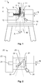
- FIG. 1 shows a first embodiment of a laser scanner 1 according to the invention.
- the scanner 1 is shown here in a front-view perspective.
- the scanner 1 comprises a base 2 and a support unit 3 (scanner frame), wherein the base 2 defines a base axis A and the support unit 3 is arranged onto the base 2 and mounted rotatable around the base axis A.
- a rotational state of the support unit 3 relative to the base 2 is determinable by means of an angle encoder.
- the support structure 3 defines and provides a fast scanning axis B which is aligned basically orthogonal to the base axis A.
- a rotation unit 10 is provided with the laser scanner 1 and arranged at the support structure 3 and mounted rotatable around the scanning axis B.
- the rotation unit 10 comprises a rotation body 11 with a scanning surface onto which a scanning mirror 12 is arranged tilted relative to the scanning axis B.
- the rotation body 11 or an axis by means of which the rotation body 11 is hold and rotated is coupled to an encoding unit which provides (continuous) determination of an angle of rotation of the rotation body 11 around the scanning axis B, i.e. relative to the support unit 3. By that an elevation angle of the rotation body 11 can be determined.
- the scanner 1 comprises a distance measuring unit 4 which provides emission of measuring light 5 and detection of reflected measuring light 5 so that a distance to an object at which the measuring light is reflected can be determined.
- the distance measuring unit 4 preferably comprises a light emitting unit like a laser diode and a photosensitive detector for detecting backscattered light. Both, emitting measuring light and receiving measuring light are deflected by means of the scanning mirror 12 and guided to an object to be measured or to the distance measuring unit 4 respectively. It is to be understood that determination of such distances can be realised by several methods well known to one of ordinary skill in the art, e.g. distances may be determined by use of the time-of-flight principle.
- the laser scanner 1 is designed for scanning a scene or scanning region as the rotation body 11 for redirecting a measuring beam (which is sent to an object as a transmission beam and the reflection of which is received as reception beam by the distance measuring unit 4) is rotating around the horizontal scanning axis B, and as a body 3 of the laser scanner 1 is rotating around the vertical base axis A.
- a measuring beam which is sent to an object as a transmission beam and the reflection of which is received as reception beam by the distance measuring unit 4
- the laser scanner 1 is designed for scanning a scene or scanning region as the rotation body 11 for redirecting a measuring beam (which is sent to an object as a transmission beam and the reflection of which is received as reception beam by the distance measuring unit 4) is rotating around the horizontal scanning axis B, and as a body 3 of the laser scanner 1 is rotating around the vertical base axis A.
- the laser scanner 1 is enabled to "sense" the surface of a scene or object and to store the scanned points characterised by their three-dimensional coordinates.
- the distances detected are assigned to angle coordinates which are provided by mentioned encoders (angle sensors) arranged around the vertical axis and the horizontal axis.
- a three-dimensional point cloud can be generated, out of which a CAD (computer aided design) model may be created.
- CAD model computer aided design
- Such CAD model may be regenerated with means of a surface recognition algorithm so that the CAD file is simplified by having unnecessary points reduced.
- Said CAD model generating may take place on a computer or process unit inside the laser scanner, or e.g. on an external computer or cloud computer by using the "raw data", i.e. the point cloud.
- the laser scanner 1 further comprises an imaging unit 15 for capturing image information related to a scanned object.
- the imaging unit 15 comprises a camera sensor and specific optics to image (and project) received light onto the senor in adjusted manner.
- the rotation body 11 comprises a curved deflecting element 13.
- the element may be provided by a hyperbolic mirror at the rotation body 11.
- the imaging unit 15 is arranged fixedly with the support structure 3 and thus defines an optical axis with defined position and orientation relative to the scanner frame 3.
- the imaging unit 15 here is fixedly arranged on the same side of the support structure 3 as the rotator (and driving unit for rotating the rotator) is arranged at.
- the camera can alternatively be arranged on the opposite side.
- the imaging unit 15 and the curved deflecting element 13 are designed so and arranged relative to each other so that - in a predetermined orientation of the rotation body 11 relative to the support structure 3 (as shown in fig. 1 ) - the imaging unit 15 corresponds with the deflecting surface 13 in desired manner.
- a parallax-free setup is provided, i.e. by the relative arrangement of the imaging unit 15 and the curved deflecting element 13 and a particular surfaces, shape and dimension of the curved deflecting element 13.
- the hyperbolic mirror 13 defines two particular focal points and is arranged with the rotation body so that one of the foci coincidences with the nodal point N of the laser canner.
- the nodal point is the intersection of the vertical (base) axis and the horizontal (rotation) axis.
- the nodal point N may also be defined by an intersection of the measuring light - or more particular of an optical axis defined by the measuring light - with the scanning mirror 12 (in particular, this point is coincident with the intersection of the A-Axis and the B-Axis).
- the hyperbolic mirror 13 is arranged with its other focal point coincidencing with the entrance pupil of the imaging unit 15 - as least in case the rotation body is set into its predefined imaging alignment as shown. A respective distance between rotation body 11 and imaging unit 15 is chosen. This setup provides parallax-free acquisition of image data.
- That provides capturing images with the camera 15 as if the centre of projection (entrance pupil of the camera) for image capturing is identical with the nodal point N for scanning.
- a main advantage of such design is that image data is generated with a reference point which corresponds to the reference point of the scanning data. Therefore, data or coordinate transformations can be avoided or at least be reduced. A correction of parallaxes is also not required or at least greatly simplified because any significant imaging-scanning-parallax is initially avoided by the specific structural design of the system. Moreover, the camera is enabled to capture the same areas and points which can be measured by the scanner, i.e. there do not exist any occlusions of points, which could be scanned but could not be imaged.
- FIG. 2 shows a further embodiment of a surveying instrument 20 according to the invention in a top-view perspective.
- the surveying instrument 20 comprises a distance measuring unit 24 which is arranges in the support structure 23 of the instrument 20.
- Measuring light 25 is reflected by a scanning mirror 22 at the rotation body 21.
- the scanning mirror 22 is a parabolic mirror.
- the rotation body 21 also comprises a curved deflecting element 33 of hyperbolic shape.
- the curved deflecting element 33 is arranged on a side of the rotation body 21 opposite to the scanning mirror 22 and with one of its focal points corresponding to the nodal point of the setup.
- the imaging unit 35 e.g. a camera, is arranged with lateral displacement relative to the rotation body 21.
- the rotation body 21 is shown in a predetermined and well defined imaging alignment so that light which impinges on the mirror 33 is guided into the imaging unit 35 in respectively defined manner.
- the imaging unit 35 comprises an optical assembly which provides imaging of incoming light on respective camera sensors of the imaging unit 25.
- the curved deflecting element 33 is a hyperbolic mirror
- the optical assembly is of specific design so that aberrations caused by the hyperbolic mirror 33 are compensated.
- the imaging unit 35 comprises three camera sensors.
- the optical assembly is respectively designed for imaging particular zones of the hyperbolic mirror 13 on the respective camera sensors so that a common and continued field of view can be imaged and captured by the camera sensors.
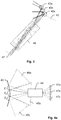
- Figure 3 depicts an embodiment of an optical assembly 46 designed for use with a hyperbolic mirror 43 (curved deflecting element) of a surveying system according to the invention and a camera sensor 47 on side of the imaging unit.
- a hyperbolic mirror 43 curved deflecting element
- the optical assembly 46 comprises seven optical elements, e.g. several types of lenses, which are linearly and successively arranged in defined manner. Such design of an optical assembly 46 may for instance be derived by use of a computer model.
- the optical assembly 46 provides imaging of particular parts of a field of view on defined locations of the assigned (to that particular field of view) camera sensor 47 by deflections at particular regions 43a-43c at the hyperbolic mirror 43.
- the camera sensor 47 may be positioned at a respective imaging plane.
- Each of the field-of-view-regions is imaged on particular regions of the sensor 47. As a result, the entire field of view can be imaged with the sensor 47.
- such or an alternative optical assembly can provide imaging not only of one field of view onto one sensor but can also provide imaging of more than one fields 45a-c of view (e.g. two or three) on a respective number of camera sensors 47a-c, as shown with figure 4a and 4b .
- Figure 4a shows an embodiment of an imaging system according to the invention in a side-view.
- the optical assembly 46' is combined with three camera sensors 47a-c and provides imaging of different fields of view on the sensors 47a-c.
- the fields of view 45a-c are defined by a deflection at the hyperbolic mirror 43.
- the zones Z 1 -Z 3 (mirror 43) and the assembly 46' are arranged so that a large and combined field of view can entirely be captured by the sensors 47a-c.
- the optical assembly 46' adapted to the hyperbolic mirror 43 images three FOV zones Z 1 -Z 3 (fields of view zones) to three camera sensors.
- FOV zones Z 1 -Z 3 fields of view zones
- a significantly enlarged elevative range can be captured with "one shot”.
- the resulting number of zones and camera sensors can vary and would typically depend on the desired field of use.
- elevation angle of each field of view may vary as well.
- Figure 4b shows the embodiment of the imaging system in a top-view. The shown elements correspond to those of figure 4a .
- Figure 4b depicts the design of the fields of view 45a-c with respect to the azimuthal direction. By azimuthal overlapping of the fields of view 45a-c, imaging of the entire and enlarged field of view provides image information over a common azimuthal range and simultaneously over the entire elevative range.
- the camera sensors 47a-c may be positioned at respective imaging points.
- alternative embodiments may furthermore comprise additional deflection elements like mirrors for optimised positioning of the sensors within the imaging unit.
- hyperbolic mirror 43 optical assembly 46' and camera sensors imaging of a significantly enlarged and continued field of view is provided.
- the resulting field of view is composed by three sub-fields each of which is defined and covered by one of the camera sensors.
- such arrangement allows acquiring image data over an elevation field angle of at least 120° and an azimuth field angle of at least 25° with "one shot”.
- Image data can be generated by each of the camera sensors and the data can be combined to one set of image data which represents the mentioned field of view.
- the elevation field angle 19 may in particular cover at least 140° depending on the design of the imaging unit. For instance there may be used a non-symmetric arrangement of the camera sensors, wherein at least one of the sensors is rotated (larger field angles relative to optical axis of the optical assembly 46).
- An embodiment of the surveying device 50 according to the invention, which defines such an enlarged field angle 19 is shown with figure 5 in a side-view perspective.
- a quasi full dome image of a surrounding of the laser scanner 1 can be captured by one 360° rotation of the support structure 3 in a certain number of steps.
- the step size can be reduced until a continuous movement results.
- a panoramic image which at least covers those areas which are also accessible by the measuring light 5 of the laser scanner can be generated that way. This is a result of a (quasi) parallax-free arrangement of the entrance pupil of the imaging unit with respect to the nodal point of the laser scanner 1 by use of the curved deflecting surface (in particular hyperbolic mirror).
- Acquiring the full dome image may require e.g. 13 different azimuth positions, wherein image data is generated in each of those positions. Depending on the provided azimuth field of view less than 13 different azimuth positions can be sufficient.
- FIG. 6 shows an embodiment of a rotation body 61 (rotor) of a rotation unit for a laser scanner according to the invention. Not shown is a driving unit and other components of the rotation unit which provide a rotational movement of the rotator 61 in use with a laser scanner.
- the rotator 61 comprises a scanning mirror 62 which provides deflection of a measuring laser light 65 for distance measuring purpose.
- the scanning mirror 62 can be a planar or curved, e.g. parabolic, mirror.
- the measuring laser light 65 is guided through a first rotator window 66a, which comprises optimized transparency with respect to a wavelength of the measuring laser light 65.
- An axis of rotation B is defined by the shape and dimensions of the rotation body 61.
- the rotation body 61 further comprises a curved deflecting element 63 which is arranged on an opposite side of a holder 67 which also provides the scanning mirror 62.
- the curved deflecting element 63 may be embodied as on piece with the holder 67, i.e. with the rotation body 61.
- the deflecting surface can be formed, in particular milled and/or polished, as one part with the rotation body (holder 67).
- the mirrors 62,63 can be milled or turned into a monolithic rotor 61.
- At least one of the reflecting mirrors 62,63 can be provided as a separate mirror element attached, in particular glued or mechanically clamped (e.g. by use of a screw), to the rotation body 61.
- the curved deflecting element 63 is designed and arranged in order to provide acquisition of image data, in particular RGB colour information for each scanning point of a scanning point cloud, in parallax-free manner.
- the curved deflecting element 63 deflects an optical axis and a correlated field of view of a camera or of a camera sensor (assigned by the laser scanner) for provision of an enlarged field of view in order to optimize acquisition of image data with reduced acquisition time.
- the rotator 61 can be hold in one rotation position and is turned around a base axis only.
- the curved deflecting element 63 can comprise an elliptical, parabolic or hyperbolic surface shape.
- the rotor 61 comprises a second window 66b which on the one hand protects the curved deflecting element 63 from contamination and on the other hand provides increased stability of the rotation body 61. Mentioned protection and stability issues also apply to the first window 66a.
- the present invention also relates to an embodiment, where the rotor 61 only comprises the two mirror elements 62,63 without having further window or protection components.
Landscapes
- Engineering & Computer Science (AREA)
- Physics & Mathematics (AREA)
- General Physics & Mathematics (AREA)
- Radar, Positioning & Navigation (AREA)
- Remote Sensing (AREA)
- Computer Networks & Wireless Communication (AREA)
- Electromagnetism (AREA)
- Multimedia (AREA)
- Signal Processing (AREA)
- Studio Devices (AREA)
- Length Measuring Devices By Optical Means (AREA)
Description
- The present invention relates to a surveying device according to the generic term of claim 1, to a rotation unit for a laser scanner according to the generic term of
claim 13 and to a method according to the generic term of claim 14. - Laser scanning is used to survey many different settings such as construction sites, building facades, industrial facilities, interior of houses, or any other applicable setting. The laser scans achieved therewith may be used to obtain accurate three-dimensional (3D) models of a setting, wherein the models consist of a point cloud. The points of such a cloud are stored by coordinates in a coordinate system, which may be defined by the laser scanning device that had recorded the point cloud. Usually, the laser scanner constitutes the origin of the coordinate system by a unit that sends out the scanning beams, in particular by the nodal point of the scanner. The points are surveyed by associating a distance measured with the scanning beam (for example, with a time-of-flight method) and the alignment under which the distance was measured. Usually, the coordinate system is a spherical coordinate system, so that a point can be characterized by a distance value, an elevation angle and an azimuth angle with reference to the origin of the coordinate system.
- Common laser scanners comprise a unit for sending out a scanning beam and for receiving the reflected beam in order to measure the distance of a point the beam was directed at. Usually, these scanners furthermore comprise means to rotatably alter the direction of the beams, commonly a vertical rotation axis (scanning axis) and a horizontal rotation axis (base axis), of which one may be a slow axis and the other one may be a fast axis, wherein both axes can be sensed with angle sensors. The rotation of the vertical axis is associated with an azimuth angle and the rotation of the horizontal axis is associated with by an elevation angle.
- The distances may be calculated with the travel time measurement (time-of-flight) method by observing the time between sending out and receiving a signal. Other possible method could be to measure the phase delay between sent and received signal. The alignment angles can be achieved with said angle sensors arranged at the vertical axis and at the horizontal axis. Other possible method could be to derive the angles from the known constant rotation speed of the axes, a point of reference, and the sampling rate of the distance measurements.
- Another means to document the environment is to acquire a panorama or full-dome image of the settings. Such an image can provide a more intuitive visualization than a point cloud or a different visualization of the environment when the image sensors capture a different spectrum than the visible one, e.g. with thermal cameras. In general, such a panorama or full-dome image is used to digitally colourise the point cloud for a more ergonomic visualization. In various applications, terrestrial laser scanning is hence supported by imaging data of a camera which is combined with a laser scanner by including them in the laser scanner instrument or mounting them on the same platform as the laser scanner.
- This is known in prior art and for example described in
US20140063489A1 ,US2016061954A1 andUS20120070077A1 . - However, prior art typically offers comparatively complicated solutions to solve parallax errors which occur due to different perspectives of a camera and a scanner.
- For example, according to
US20140063489A1 , the camera is incorporated inside the scanner and components are arranged such that the camera and the scanner have the same optical axis. However, the entrance pupil location of the camera is not at the same location as the nodal point. Therefore, only the central point of the camera has the same perspective as the scanner. Other points in the field of view (FOV) of the camera will have a parallax error. This construction requires a high technical effort. -
DE 20 2013 001 538 U1 andDE 20 2010 017 899 U1 relate to laser scanners which provide generation of a point cloud by scanning and capturing image information with defined, in particular parallax-free, relation to the point cloud data. - According to
US20120070077A1 , a camera is a posteriori brought virtually into a position close to the position where the scanner had been to scan the environment. This process requires high processing effort with limited success. Artefacts will remain due to the relatively large parallax between entrance pupil of camera and nodal point of scanner. - If a camera on a laser scanner does not share a single projective centre with the scanner unit, then a parallax is introduced. As a consequence, an incorrect reference of image data to scanning data may happen. The parallax effect takes place at regions where the camera "looks" under a significantly different angle than the scanner to a certain object point and therefore "sees" this point at a different 3D-position than the scanner "sees" it. Additionally, there can be points, "seen" by the scanner, but not by the camera, which results in 3D-points without colour data. In order to avoid such incorrect reference of colourisation or missing of colour data due to the camera's parallax, an algorithm for identifying these particular regions can be implemented including the use of 3D data and for correcting colourisation. Such algorithmic approach, however, is comparatively time-consuming and resource (energy) consuming and still cannot fully correct colourisation, especially in the near field. Therefore artefacts will occur in the colorized 3D point cloud data.
- It is therefore an object of the present invention to provide an improved surveying instrument allowing for a provision of image acquisition with high precision, exact reference to gathered scanning data and in particular with no missing colour data.
- Laser scanner can generate a point cloud of a scenery around 360° horizontally and close to 180° vertically based on laser-distance and angle encoder measurements. In general, missing is the colour information and the photographic picture like visualization of the scenery. Therefore the extension by a camera system is worthwhile for presenting the data and documentation. Critical condition in this kind of sensor fusion of the two measurement approaches is the parallax-free condition to avoid unwanted artefacts that cause distance values (voxels) with wrong colour information, that could make the final scan result appear unreliable
- The present invention proposes an approach of achieving a full-dome image at nearly parallax-free conditions in particular with a laser scanner device.
- One major issue for stitched full dome images is the so called parallax. Parallax occurs for instance, when an entrance pupil centre of the lens is not coincident with the intersection of the vertical (base) and horizontal (rotation) axis of a laser scanner.
- Parallax generally means that an object point is imaged under different viewing angles, caused by a position change of the entrance pupil centre. This happens e.g., when a camera is rotated not around its entrance pupil centre. The angle difference is commonly called the parallax angle.
- "Parallax" also means the distance between the entrance pupil of the imaging lens and the intersection of the vertical and horizontal axis of the scanner. Such distance is to be minimised, ideally down to zero. If this distance is zero, the viewing angle on an object point does not change, when the camera is rotated, and therefore the parallax angle remains zero.
- In imaging, the location of the entrance pupil centre can also determine the perspective centre that may also be called "nodal point". So when using the term "nodal point" in context of e.g. panorama photography, one should keep in mind, the "nodal point" should be located at the entrance pupil centre of the camera lens.
- One consequence of an existing parallax is that there are regions, which are "seen" (measured) by the distance measuring unit of a laser scanner (EDM), but not by the imaging unit. Another parallax consequence is a lateral position error. This lateral error can typically be calibrated and by that compensated.
- Ideally, the parallax of a panorama imaging system is zero. But due to lens-intrinsic pupil aberrations, tolerances and other setup-given effects, a real system may always have a residual parallax. But real systems also always have a non-ideal contrast function, i.e. they have a blur. So if the parallax-caused lateral error is smaller than this blur, the system can be considered as parallax-free regarding position error.
- Generally, a real system has never zero parallax due to pupil aberration, tolerances etc. But from customers point of view a system is close to zero parallax, when it does not show visible parallax effects, in this way one can say the systems behaves like a "quasi-parallax-free" setup. This is understood in the present invention as a parallax-free setup.
- The present invention is based on the idea to provide a less complex and comparatively low cost solution of basically parallax-free image acquisition with a surveying instrument, e.g. a laser scanner. One main element of such solution is a particular design of the rotator of an instrument. Such rotation unit and its rotation body are equipped with one specific curved deflecting surface (in addition to a scanning mirror which is also provided with the rotation body). The curved deflecting element can preferably be provided by an element of hyperbolic shape (a hyperboloid of rotation) which defines two focal points. A camera device, which is assigned to the deflecting surface is arranged at a support structure of the scanner and thus is fixed relative to the rotation body.
- By use of a curved deflecting element the field of view of an assigned camera sensor can be enlarged both in elevation and azimuth direction.
- These two components - the rotation body and the camera - are arranged and designed so that the viewing axis and therefore the field of view of the camera is deflected and defined by the deflecting element in defined manner. By that image acquisition as if the entrance pupil of the camera coincides with the nodal point of the laser scanner can be provided.
- The deflection can be provided in one particular alignment (orientation) of the rotation body around the fast scanning axis. This means, the rotation body is controlled to be orientated into such defined alignment and image acquisition can be performed by rotating or swivelling the support structure around the base axis while keeping the rotation angle for the rotation body constant. By that, a panoramic image or - depending on an elevation field angle of the resulting field of view - a full dome image can be acquired.
- In other words and more general, the invention relates to a surveying device which in particular is embodied as a geodetic surveying device, in particular as a laser scanner. The surveying device comprises a base which defines a base axis and a support structure which is arranged to be rotatable around the base axis and which defines a scanning axis which is oriented basically orthogonal relative to the base axis. Furthermore, a light emitting unit for emitting measuring light, in particular a laser diode, and a light receiving unit comprising a (photosensitive) detector for detecting reflected measuring light are provided.
- The surveying device also comprises a rotation unit mounted on the support structure for providing emission and reception of measuring light in defined and variable (due to rotations) directions, wherein the rotation unit comprises a rotation body which is mounted rotatable around the scanning axis and the rotation body comprises at least one slanted scanning surface which comprises a scanning mirror which is arranged tilted relative to the scanning axis and provides defined deflection of the measuring light. The scanning mirror may be of parabolic shape. Such design allows acquiring distances and directions of a plurality of measuring points and by that to generate a point cloud which represents a respectively measuring region. The rotation unit may further comprise a driving unit (motor) for automated and controlled rotation of the rotation body. The rotation unit can further comprise a shaft by which the rotation body is connected to the motor and/or an angle encoder for determination of a rotational position.
- An imaging unit for capturing an image of a scanning region and a controlling and processing unit are arranged as well.
- According to the invention, the rotation body comprises a curved deflecting element different from the scanning surface. The imaging unit comprises at least one camera sensor which is fixedly arranged with the support structure so that an optical axis of the camera sensor is directed towards the rotation body. The imaging unit and the rotation body are designed so and arranged relative to each other so that only in a predetermined imaging-alignment of the rotation body around the rotation axis
- the optical axis of the at least one camera sensor is deflected by the curved deflecting element by a desired angle and direction and
- a field of view of the at least one camera sensor is deflected and defined by the deflection of the optical axis so that the field of view comprises a defined and enlarged field angle (compared to a field angle provided with the imaging unit) around the rotation axis (elevation), in particular in a plane at least basically orthogonal to or inclined in defined manner relative to the rotation axis.
- A spread of the field of view of the camera sensor or the imaging unit, respectively, can be provided by use of the curved deflecting element. This allows gathering image information of a larger region with one particular alignment of the rotation element and one shot.
- It is to be understood in context of the present invention that the field of view of the imaging unit may not only be extended with respect to an elevation angle but may also be extended with respect to an azimuth angle, i.e. around the base axis.
- A comparatively large field angle in the plane at least basically orthogonal to the rotation axis of the rotation body would relate in particular to a significant smaller field angle in a plane parallel to the rotation axis of the surveying instrument. Hence, there may be provided a field of view with a larger elevation field angle and a smaller azimuth field angle.
- Therefore, the surveying instrument according to the invention enables to bring and hold the rotation body in a well defined and known orientation, e.g. so that the rotation body provides a defined rotation angle around the rotation (scanning) axis, and by that enabling the camera sensor (imaging unit) to see at least part of the scanning region which can be measured by means of scanning with the measuring light. A particular arrangement of camera and deflecting surface and a particular design of the rotation body can also provide that respective images are captured as if the entrance pupil of the camera is located in or near the nodal point of the surveying instrument and thus results in parallax-free or quasi-parallax-free image capturing.
- In particular, the camera sensor of the imaging can be provided as visual camera sensor or as infrared sensor. Regarding the curved deflecting element, the surveying device comprises such curved deflecting element preferably having elliptical, parabolic or hyperbolic shape (shape of an ellipsoid, paraboloid or hyperboloid of rotation).
- The curved deflecting element can be embodied as a hyperboloid having a reflective surface, in particular as a hyperbolic mirror.
- According to the invention, the curved deflecting element defines a first and a second geometric focal point and the curved deflecting element is arranged so that the first focal point positionally coincides with an intersection point of the base axis and the rotation axis, in particular with the nodal point of the surveying device. The second focal point positionally coincides with an entrance pupil for the at least one camera sensor (e.g. entrance pupil of the imaging unit) in the imaging-alignment the rotation body.
- A hyperbolic mirror has two foci. This allows, realizing a wide-angle lens with zero parallax by placing a hyperbolic mirror with one focus at the intersection of the horizontal and vertical scanner axis (nodal point). The imaging lens (of the imaging unit) may then be placed with its entrance pupil at the other focus of the hyperbolic mirror. In addition, the negative refracting power of the hyperbolic mirror helps to achieve wide angle imaging.
-
Figure 7 shows the principle of applied hyperbolic geometry and depicts ahyperbolic body 103 with two focal point 101,102 defined by the shape of thehyperbolic body 103. - In an embodiment the imaging unit comprises at least two camera sensors. The imaging unit and the sensors are fixedly arranged with the support structure so that the optical axes of the at least two camera sensors are directed towards the rotation body, in particular indirectly by deflections of the optical axes. There may be a mirror which deflects one or more optical axes.
- In such embodiment, the imaging unit and the rotation body can be designed so and arranged relative to each other so that in the predetermined imaging-alignment of the rotation body around the rotation axis the optical axes of the at least two camera sensors are deflected by the curved deflecting element by respectively desired angles and directions and sub-fields of view of the at least two camera sensor are deflected and defined by the deflection of the optical axes so that one combined and continued wide-angle (elevation) field of view around the rotation axis, in particular with reference to the angle of rotation of the rotation body, in particular with reference to an elevation angle, is provided as a combination of the sub-fields of view.
- The continued wide-angle (elevation) field of view preferably covers an angle of at least 100°, in particular at least 120° or at least 150°, around the rotation axis, in particular with respect to an elevation angle.
- Correspondingly, the continued wide-angle azimuthal field of view can cover an angle of at least 25°, in particular at least 30°, around the base axis, in particular with respect to an azimuth angle.
- Each of the sub-fields of view - which is defined by a deflection by means of the curved deflecting element in the predetermined imaging-alignment - can partly cover the wide-angle elevation field of view, wherein an overlap of adjacent elevation sub-fields of view may be provided.
- Of course, image processing of the image data gathered by means of the three camera sensors can be provided in a manner so that there results one set of image data comprising data from all the three camera sensors. E.g. matching, blending and composition (e.g. stitching) of image data is performed according to approaches well known in the art. Based on such unified image data e.g. colouring of a scanning point cloud is provided in improved manner.
- Referring to the design of the imaging unit, the imaging unit can comprise an optical assembly which images a field of view zone, which is provided by the curved deflecting element, to the at least one camera sensor, in particular images three sub-fields of view zones to respective three camera sensors. Therefore, the optical assembly enables to capture image data with the camera sensor in a manner adjusted to a particular design of the curved deflecting element, e.g. adjusted to a hyperbolic mirror. Possible deviations in deflection generated by the curved deflecting element can be compensated by that.
- Thus, the optical assembly can provide compensated imaging of light which is deflected by the curved deflecting element on the at least one cameras sensor.
- In particular, the optical assembly may provide compensation of a refractive effect and/or an asymmetric aberration resulting from a curved design of the curved deflecting element.
- According to an embodiment of the invention, the optical assembly comprises a set of at least five (e.g. seven) successively arranged optical elements, in particular lenses or other refractive elements. The five optical elements represent a result of a calculation which is based on a design model which considers a design of the curved deflecting element. This allows adjusted imaging of light from the curved deflecting element onto at least one camera sensor.
- In case of e.g. using three camera sensors, respective three deflection zones on side of the curved deflecting element are imaged on the three sensors, i.e. light impinging on one of the zones is guided to a respective camera sensor which is assigned to that zone.
- Now referring to an embodiment wherein the curved deflecting element is built as a hyperbolic mirror. In comparison with a plane mirror a hyperbolic mirror has a refractive impact due to the curved surface like a lens element. Additionally the hyperbolic mirror may generate some specific asymmetric aberrations due to the asymmetry of the surface shape in the sub-aperture of each field point. Therefore the optical assembly must be design including the hyperbolic surface into the design model.
- An optical assembly adapted to the hyperbolic mirror may image three FOV zones to the three camera sensors. The three sensors FOVs can be combined with a beam splitter and mirror system.
- In one embodiment every sensor has exactly the same imaging conditions and therefore the same performance.
- Due to the non-planar surface shape of the hyperbolic mirror in the rotor, the refractive power is split between the mirror and the following lens elements of the optical assembly. Therefore, the alignment of the lens inside the laser scanner housing can refer to the mirror in a sensitive way. In the course of aligning the rotor and the imaging unit, full 6-DOF orientation between optical assembly and mirror needs to be considered, because otherwise decentration, tilt, defocus will be introduced, which may decreases the total performance. The position of the mirror may thus be sensitive for the performance like a lens element.
- In particular, the entrance pupil or centres of projection of the imaging unit is positioned virtually in the nodal point of the system. In other words, the entrance pupil of all fields of view (defined by the camera sensors, the lens assembly and the respective deflecting surface) coincide with the intersection point of a horizontal and vertical axis of the surveying device (nodal point). By that, a parallax free full-dome image can be captured.
- As a result the imaging setup acts as one particular camera which has virtually a single projective centre. This centre virtually coincides with the nodal point of the surveying device that may be embodied as a laser scanner. The field-of-view is somehow optimised in order to minimise acquisition time for a full-dome image.
- In one embodiment the controlling and processing unit provides an imaging functionality which is configured so that the image data is recordable with each of the at least one camera sensors in case the rotation body is in the predetermined imaging-alignment. Additionally or alternatively, the controlling and processing unit is configured to control a step of rotating the rotation body around the rotation axis so that the rotation body is brought in the predetermined imaging-alignment. Acquisition of image data may be started after having reached the imaging-alignment.
- The rotation body of the surveying device can be designed so that the scanning mirror is arranged on a front side of the rotation body and the curved deflecting element is arranged on the backside of the rotation body.
- Furthermore, the rotation body may be arranged in a cylindrical cover which is designed to provide at least a first transmission window for emission and reception of the measuring light and a second transmission window for reception of light for capturing image data by the at least one camera sensor.
- The predetermined imaging-alignment can be provided by one particular range of rotation around the rotation axis, or by one particular angle of rotation around the rotation axis.
- In particular the imaging unit can be used for navigation (SLAM), e.g. when carrying the laser scanner from a first to a second scan position. By that, improved referencing of respective scanning positions and coordinate systems can be provided.
- The invention also relates to a rotation body of a rotation unit for a surveying device, in particular laser scanner. The rotation body is adapted to be mounted on the surveying device for providing defined emission and reception of measuring light by rotation around a rotation axis. The rotation axis is defined by a particular design, in particular by shape and dimension, of the rotation body, wherein the rotation body comprises at least one slanted scanning surface which comprises a scanning mirror which is arranged tilted relative to the rotation axis and provides defined deflection of the measuring (laser) light.
- The rotation body comprises a curved deflecting element different from the scanning surface and the curved deflecting element provides - in its desired mounting on the surveying device - defined deflection of an optical axis of a camera sensor of the surveying device and an enlargement of its field of view.
- In particular, the rotation body is designed according to any one of above specification relating to the rotation body of the described surveying device. Such particular design is to be understood as not being limited to specific design of the body itself but has to be understood as including e.g. realisations of the deflecting surfaces or the like.
- In one embodiment, to decrease the complexity and the manufacturing cost of a parabolic (scanning) and a hyperbolic (imaging) mirror the body can be designed as a multi-body part. In this case it is possible to manufacture the paraboloid and hyperboloid separately and adjust those mirrors together in a second step.
- The hyperbolic mirror can be automatically pre-adjusted to the parabolic mirror with two magnets. Afterwards movements in plane can be possible of e.g. approximately 0.5mm. The imaging mirror can be fixed with adhesive as soon as it is adjusted to the optical axis.
- A wall thickness in the middle of the parabolic mirror can be chosen to be quite small. If the rotor rotates with a spin speed of e.g. 6000 rpm, the mirror will be bent affecting the optical performance. Therefore, a pin screw at the top of the curved imaging mirror can function as a limit stop and may not be tightened.
- To decrease an assembly tolerance and to increase the stiffness of the affected system a supporting frame (cover) may be advantageous.
- Based on the morphology and the geometry of the hyperbole element and the large FOV the integration of a protection glass may be realised by using a quite thin bended window glass.
- For increasing mechanical stability Gorilla glass can be used as an adequate cover. An alternative or additional solution might be a laminated thin sheet of glass.
- The invention also relates to a method of generating quasi full-dome image data of a scanning region by use of a surveying device according to above in controlled and automatic manner. Following steps are performed for the method:
- setting up the surveying device at a defined position,
- automatically (initiated and controlled by an algorithm) moving the rotation body into the predetermined imaging-alignment,
- automatically capturing a first set of image data by means of the at least one camera sensor,
- automatically re-orienting the support structure around the base axis by a defined angle according to a provided azimuth field of view of the at least one camera sensor, wherein the rotation body is held in the predetermined imaging-alignment,
- automatically capturing a further set of image data by means of the at least one camera sensor, and
- repeating the steps of re-orienting the support structure and of capturing a further set of image data until the scanning region is covered over an azimuth angle of 360°, in particular repeating the steps of re-orienting the support structure and of capturing a further set of image data for at least six, in particular eleven or twelve, times.
- According to an embodiment, the rotation body is arranged in a cylindrical cover which is designed to provide at least a first transmission window for emission and reception of the measuring light and a second transmission window for reception of light for capturing images by the at least one camera. Such cover can help protecting the optical elements from environmental influences.
- The devices and method according to the invention are described or explained in more detail below, purely by way of example, with reference to working examples shown schematically in the drawings. Specifically,
- fig. 1
- show a first embodiment of a surveying device embodied as a laser scanner according to the invention;
- fig. 2
- shows a top-view of an embodiment of a laser scanner according to the invention;
- fig. 3
- shows a laser scanner according to the invention in side-view;
- figs. 4a-b
- show an embodiment of an imaging system according to the invention;
- fig. 5
- shows a further embodiment of a rotation body of a surveying device according to the invention;
- fig. 6
- shows an embodiment of an optical assembly of an imaging unit of a laser scanner according to the invention; and
- fig. 7
- shows the principle of hyperbolic geometry as applied with an embodiment of the invention.
-
Figure 1 shows a first embodiment of a laser scanner 1 according to the invention. The scanner 1 is shown here in a front-view perspective. The scanner 1 comprises abase 2 and a support unit 3 (scanner frame), wherein thebase 2 defines a base axis A and thesupport unit 3 is arranged onto thebase 2 and mounted rotatable around the base axis A. A rotational state of thesupport unit 3 relative to thebase 2 is determinable by means of an angle encoder. - The
support structure 3 defines and provides a fast scanning axis B which is aligned basically orthogonal to the base axis A. Arotation unit 10 is provided with the laser scanner 1 and arranged at thesupport structure 3 and mounted rotatable around the scanning axis B. Therotation unit 10 comprises arotation body 11 with a scanning surface onto which ascanning mirror 12 is arranged tilted relative to the scanning axis B. In addition, therotation body 11 or an axis by means of which therotation body 11 is hold and rotated is coupled to an encoding unit which provides (continuous) determination of an angle of rotation of therotation body 11 around the scanning axis B, i.e. relative to thesupport unit 3. By that an elevation angle of therotation body 11 can be determined. - Furthermore, the scanner 1 comprises a
distance measuring unit 4 which provides emission of measuring light 5 and detection of reflected measuring light 5 so that a distance to an object at which the measuring light is reflected can be determined. Thedistance measuring unit 4 preferably comprises a light emitting unit like a laser diode and a photosensitive detector for detecting backscattered light. Both, emitting measuring light and receiving measuring light are deflected by means of thescanning mirror 12 and guided to an object to be measured or to thedistance measuring unit 4 respectively. It is to be understood that determination of such distances can be realised by several methods well known to one of ordinary skill in the art, e.g. distances may be determined by use of the time-of-flight principle. - As can be seen from the combination of the rotatable elements and the
distance measuring unit 4, the laser scanner 1 is designed for scanning a scene or scanning region as therotation body 11 for redirecting a measuring beam (which is sent to an object as a transmission beam and the reflection of which is received as reception beam by the distance measuring unit 4) is rotating around the horizontal scanning axis B, and as abody 3 of the laser scanner 1 is rotating around the vertical base axis A. By sending out and receiving measuring light (e.g. laser signals) at respective positions of the components rotating around said axes A and B, thereby applying EDM (electronic distance measurement) techniques known from prior art, such as travel time measurement, the laser scanner 1 is enabled to "sense" the surface of a scene or object and to store the scanned points characterised by their three-dimensional coordinates. The distances detected are assigned to angle coordinates which are provided by mentioned encoders (angle sensors) arranged around the vertical axis and the horizontal axis. During the scan, a three-dimensional point cloud can be generated, out of which a CAD (computer aided design) model may be created. Such CAD model may be regenerated with means of a surface recognition algorithm so that the CAD file is simplified by having unnecessary points reduced. Said CAD model generating may take place on a computer or process unit inside the laser scanner, or e.g. on an external computer or cloud computer by using the "raw data", i.e. the point cloud. - The laser scanner 1 further comprises an
imaging unit 15 for capturing image information related to a scanned object. Theimaging unit 15 comprises a camera sensor and specific optics to image (and project) received light onto the senor in adjusted manner. - Correspondingly, the
rotation body 11 comprises acurved deflecting element 13. The element may be provided by a hyperbolic mirror at therotation body 11. - The
imaging unit 15 is arranged fixedly with thesupport structure 3 and thus defines an optical axis with defined position and orientation relative to thescanner frame 3. - As can be seen, the
imaging unit 15 here is fixedly arranged on the same side of thesupport structure 3 as the rotator (and driving unit for rotating the rotator) is arranged at. Of course, depending on the design of the optical arrangement, the camera can alternatively be arranged on the opposite side. - The
imaging unit 15 and thecurved deflecting element 13 are designed so and arranged relative to each other so that - in a predetermined orientation of therotation body 11 relative to the support structure 3 (as shown infig. 1 ) - theimaging unit 15 corresponds with the deflectingsurface 13 in desired manner. This means that the field of view of camera 15 (exemplarily) is deflected by the deflectingelement 13 and thus defined in a manner to provide a field ofview 16 having a comparatively great field angle in rotation direction of the rotation body 11 (rotation around the rotation axis B; elevation angle) and a smaller but also enlarged field angle in azimuthal direction. - According to the invention, by that arrangement a parallax-free setup is provided, i.e. by the relative arrangement of the
imaging unit 15 and thecurved deflecting element 13 and a particular surfaces, shape and dimension of thecurved deflecting element 13. - The
hyperbolic mirror 13 defines two particular focal points and is arranged with the rotation body so that one of the foci coincidences with the nodal point N of the laser canner. The nodal point is the intersection of the vertical (base) axis and the horizontal (rotation) axis. The nodal point N may also be defined by an intersection of the measuring light - or more particular of an optical axis defined by the measuring light - with the scanning mirror 12 (in particular, this point is coincident with the intersection of the A-Axis and the B-Axis). Furthermore, thehyperbolic mirror 13 is arranged with its other focal point coincidencing with the entrance pupil of the imaging unit 15 - as least in case the rotation body is set into its predefined imaging alignment as shown. A respective distance betweenrotation body 11 andimaging unit 15 is chosen. This setup provides parallax-free acquisition of image data. - That provides capturing images with the
camera 15 as if the centre of projection (entrance pupil of the camera) for image capturing is identical with the nodal point N for scanning. - A main advantage of such design is that image data is generated with a reference point which corresponds to the reference point of the scanning data. Therefore, data or coordinate transformations can be avoided or at least be reduced. A correction of parallaxes is also not required or at least greatly simplified because any significant imaging-scanning-parallax is initially avoided by the specific structural design of the system. Moreover, the camera is enabled to capture the same areas and points which can be measured by the scanner, i.e. there do not exist any occlusions of points, which could be scanned but could not be imaged.
-
Figure 2 shows a further embodiment of a surveyinginstrument 20 according to the invention in a top-view perspective. The surveyinginstrument 20 comprises adistance measuring unit 24 which is arranges in thesupport structure 23 of theinstrument 20. Measuringlight 25 is reflected by ascanning mirror 22 at therotation body 21. Thescanning mirror 22 is a parabolic mirror. - The
rotation body 21 also comprises acurved deflecting element 33 of hyperbolic shape. Thecurved deflecting element 33 is arranged on a side of therotation body 21 opposite to thescanning mirror 22 and with one of its focal points corresponding to the nodal point of the setup. - The
imaging unit 35, e.g. a camera, is arranged with lateral displacement relative to therotation body 21. Therotation body 21 is shown in a predetermined and well defined imaging alignment so that light which impinges on themirror 33 is guided into theimaging unit 35 in respectively defined manner. - For that, the
imaging unit 35 comprises an optical assembly which provides imaging of incoming light on respective camera sensors of theimaging unit 25. As thecurved deflecting element 33 is a hyperbolic mirror, the optical assembly is of specific design so that aberrations caused by thehyperbolic mirror 33 are compensated. - The
imaging unit 35 comprises three camera sensors. The optical assembly is respectively designed for imaging particular zones of thehyperbolic mirror 13 on the respective camera sensors so that a common and continued field of view can be imaged and captured by the camera sensors. -
Figure 3 depicts an embodiment of anoptical assembly 46 designed for use with a hyperbolic mirror 43 (curved deflecting element) of a surveying system according to the invention and acamera sensor 47 on side of the imaging unit. - The
optical assembly 46 comprises seven optical elements, e.g. several types of lenses, which are linearly and successively arranged in defined manner. Such design of anoptical assembly 46 may for instance be derived by use of a computer model. - The
optical assembly 46 provides imaging of particular parts of a field of view on defined locations of the assigned (to that particular field of view)camera sensor 47 by deflections atparticular regions 43a-43c at thehyperbolic mirror 43. Thecamera sensor 47 may be positioned at a respective imaging plane. Each of the field-of-view-regions is imaged on particular regions of thesensor 47. As a result, the entire field of view can be imaged with thesensor 47. - Moreover, such or an alternative optical assembly can provide imaging not only of one field of view onto one sensor but can also provide imaging of more than one
fields 45a-c of view (e.g. two or three) on a respective number ofcamera sensors 47a-c, as shown withfigure 4a and4b . -
Figure 4a shows an embodiment of an imaging system according to the invention in a side-view. The optical assembly 46' is combined with threecamera sensors 47a-c and provides imaging of different fields of view on thesensors 47a-c. The fields ofview 45a-c are defined by a deflection at thehyperbolic mirror 43. This means that there are particular zones Z1-Z3 at the mirror, wherein each of which is imaged on a particularly assignedsensor 47a-c by means of the optical assembly 46'. The zones Z1-Z3 (mirror 43) and the assembly 46' are arranged so that a large and combined field of view can entirely be captured by thesensors 47a-c. In other words, the optical assembly 46' adapted to thehyperbolic mirror 43 images three FOV zones Z1-Z3 (fields of view zones) to three camera sensors. By such combination of fields of view a significantly enlarged elevative range can be captured with "one shot". Of course, it is to be understood that the resulting number of zones and camera sensors can vary and would typically depend on the desired field of use. In addition the elevation angle of each field of view may vary as well. -
Figure 4b shows the embodiment of the imaging system in a top-view. The shown elements correspond to those offigure 4a .Figure 4b depicts the design of the fields ofview 45a-c with respect to the azimuthal direction. By azimuthal overlapping of the fields ofview 45a-c, imaging of the entire and enlarged field of view provides image information over a common azimuthal range and simultaneously over the entire elevative range. - The
camera sensors 47a-c may be positioned at respective imaging points. Of course, alternative embodiments may furthermore comprise additional deflection elements like mirrors for optimised positioning of the sensors within the imaging unit. - As a result of such arrangement of
hyperbolic mirror 43, optical assembly 46' and camera sensors imaging of a significantly enlarged and continued field of view is provided. The resulting field of view is composed by three sub-fields each of which is defined and covered by one of the camera sensors. In other words and more specific, such arrangement allows acquiring image data over an elevation field angle of at least 120° and an azimuth field angle of at least 25° with "one shot". Image data can be generated by each of the camera sensors and the data can be combined to one set of image data which represents the mentioned field of view. - The
elevation field angle 19 may in particular cover at least 140° depending on the design of the imaging unit. For instance there may be used a non-symmetric arrangement of the camera sensors, wherein at least one of the sensors is rotated (larger field angles relative to optical axis of the optical assembly 46). An embodiment of thesurveying device 50 according to the invention, which defines such anenlarged field angle 19 is shown withfigure 5 in a side-view perspective. - By rotating and holding the
rotation body 11 in the predetermined imaging orientation relative to the fixed cameras and swivelling thesupport structure 3 around the base axis A while continuously or stepwise taking pictures with the camera sensors, a quasi full dome image of a surrounding of the laser scanner 1 can be captured by one 360° rotation of thesupport structure 3 in a certain number of steps. The step size can be reduced until a continuous movement results. More particular, a panoramic image which at least covers those areas which are also accessible by the measuringlight 5 of the laser scanner can be generated that way. This is a result of a (quasi) parallax-free arrangement of the entrance pupil of the imaging unit with respect to the nodal point of the laser scanner 1 by use of the curved deflecting surface (in particular hyperbolic mirror). - Acquiring the full dome image may require e.g. 13 different azimuth positions, wherein image data is generated in each of those positions. Depending on the provided azimuth field of view less than 13 different azimuth positions can be sufficient.
-
Figure 6 shows an embodiment of a rotation body 61 (rotor) of a rotation unit for a laser scanner according to the invention. Not shown is a driving unit and other components of the rotation unit which provide a rotational movement of therotator 61 in use with a laser scanner. - The
rotator 61 comprises ascanning mirror 62 which provides deflection of a measuringlaser light 65 for distance measuring purpose. Thescanning mirror 62 can be a planar or curved, e.g. parabolic, mirror. The measuringlaser light 65 is guided through afirst rotator window 66a, which comprises optimized transparency with respect to a wavelength of the measuringlaser light 65. An axis of rotation B is defined by the shape and dimensions of therotation body 61. - The
rotation body 61 further comprises acurved deflecting element 63 which is arranged on an opposite side of aholder 67 which also provides thescanning mirror 62. Thecurved deflecting element 63 may be embodied as on piece with theholder 67, i.e. with therotation body 61. In other words, the deflecting surface can be formed, in particular milled and/or polished, as one part with the rotation body (holder 67). Hence, themirrors monolithic rotor 61. - Alternatively, at least one of the reflecting mirrors 62,63 can be provided as a separate mirror element attached, in particular glued or mechanically clamped (e.g. by use of a screw), to the
rotation body 61. - The
curved deflecting element 63 is designed and arranged in order to provide acquisition of image data, in particular RGB colour information for each scanning point of a scanning point cloud, in parallax-free manner. Thecurved deflecting element 63 deflects an optical axis and a correlated field of view of a camera or of a camera sensor (assigned by the laser scanner) for provision of an enlarged field of view in order to optimize acquisition of image data with reduced acquisition time. Therotator 61 can be hold in one rotation position and is turned around a base axis only. - The
curved deflecting element 63 can comprise an elliptical, parabolic or hyperbolic surface shape. - The
rotor 61 comprises asecond window 66b which on the one hand protects thecurved deflecting element 63 from contamination and on the other hand provides increased stability of therotation body 61. Mentioned protection and stability issues also apply to thefirst window 66a. - It is to be understood, that the present invention also relates to an embodiment, where the
rotor 61 only comprises the twomirror elements - Although the invention is illustrated above, partly with reference to some specific embodiments, it must be understood that numerous modifications and combinations of different features of the embodiments can be made and that the different features can be combined with each other or with laser scanners known from prior art.
Claims (14)
- Surveying device (1,20,50), in particular geodetic surveying device, in particular laser scanner, comprising• a base (2) which defines a base axis (A),• a support structure (3,23) which is arranged to be rotatable around the base axis (A) and which defines a rotation axis (B) which is oriented basically orthogonal relative to the base axis (A),• a light emitting unit, in particular a fiber laser or laser diode, for emitting measuring light (5,25,65),• a light receiving unit comprising a detector for detecting reflected measuring light (5,25,65),• a rotation unit (10) mounted on the support structure (3,23) for providing emission and reception of measuring light (5,25,65) in defined directions, wherein□ the rotation unit (10) comprises a rotation body (11,21,61) which is mounted rotatable around the rotation axis (B) and□ the rotation body (11,21,61) comprises at least one slanted scanning surface which comprises a scanning mirror (12,22,62) which is arranged tilted relative to the rotation axis (B) and provides defined deflection of the measuring light (5,25,65),• an imaging unit (15,35) for capturing image data of a scanning region and• a controlling and processing unit,characterised in that• the rotation body (11,21,61) comprises a curved deflecting element (13,33,43,63) different from the scanning surface,• the imaging unit (15,35) comprises at least one camera sensor (47,47a-c), wherein the imaging unit (15,35) is fixedly arranged with the support structure (3,23) so that an optical axis of the camera sensor is directed towards the rotation body (11,21,61), and• the imaging unit (15,35) and the rotation body (11,21,61) are designed so and arranged relative to each other so that only in a predetermined imaging-alignment of the rotation body (11,21,61) around the rotation axis (B)□ the optical axis of the at least one camera sensor (47,47a-c) is deflected by the curved deflecting element (13,33,43,63) by a desired angle and direction, and□ a field of view of the at least one camera sensor (47,47a-c) is deflected and defined by the deflection of the optical axis so that the field of view comprises a defined field angle around the rotation axis (B), in particular in a plane at least basically orthogonal to or inclined in defined manner relative to the rotation axis (B),• the curved deflecting element (13,33,43,63) defines a first and a second geometric focal point (101,102) and• the curved deflecting element (13,33,43,63) is arranged so that□ the first focal point (101),positionally coincides with an intersection point of the base axis (A) and the rotation axis (B), said intersection point being the nodal point (N) of the surveying device (1,20,50), and□ the second focal point (102) at least basically positionally coincides with an entrance pupil for the at least one camera sensor (47,47a-c) in the imaging-alignment of the rotation body (11,21,61).
- Surveying device (1,20,50) according to claim 1,
characterised in that
the curved deflecting element (13,33,43,63)• comprises an elliptical, parabolic or hyperbolic shape or• is embodied as a hyperboloid having a reflective surface, in particular as a hyperbolic mirror. - Surveying device (1,20,50) according to claim 1 or 2,
characterised in that• the imaging unit (15,35) comprises at least two camera sensors (47,47a-c), wherein the imaging unit (15,35) is fixedly arranged with the support structure (3,23) so that the optical axes of the at least two camera sensors (47,47a-c) are directed towards the rotation body (11,21,61), in particular indirectly by deflections of the optical axes,• the imaging unit (15,35) and the rotation body (11,21,61) are designed so and arranged relative to each other so that in the predetermined imaging-alignment of the rotation body (11,21,61) around the rotation axis (B)▪ the optical axes of the at least two camera sensors (47,47a-c) are deflected by the curved deflecting element (13,33,43,63) by respectively desired angles and directions and▪ sub-fields of view (45a-c) of the at least two camera sensors (47,47a-c) are deflected and defined by the deflection of the optical axes so that one combined and continued wide-angle elevation field of view around the rotation axis (B), in particular with reference to the angle of rotation of the rotation body (11,21,61), in particular with reference to an elevation angle, is provided as a combination of the sub-fields of view (45a-c). - Surveying device (1,20,50) according to claim 3,
characterised in that
the continued wide-angle elevation field of view covers• an angle of at least 100°, in particular at least 120° or at least 150°, around the rotation axis (B), in particular with respect to an elevation angle, and/or• an angle of at least 25°, in particular at least 30°, around the base axis (A), in particular with respect to an azimuth angle. - Surveying device (1,20,50) according to claim 3 or 4,
characterised in that
each of the sub-fields of view (45a-c) which is defined by a deflection by means of the curved deflecting element (13,33,43,63) in the predetermined imaging-alignment partly covers the wide-angle elevation field of view, wherein an overlap of adjacent elevation sub-fields of view (45a-c) is provided. - Surveying device (1,20,50) according to any one of the claims 1 to 5,
characterised in that
the imaging unit comprises an optical assembly (46,46') which images a field of view zone (Z1-Z3) which is provided by the curved deflecting element (13,33,43,63) to the at least one camera sensor (47,47a-c), in particular images three sub-fields of view zones (Z1-Z3) to respective three camera sensors (47a-c). - Surveying device (1,20,50) according to claim 6,
characterised in that
the optical assembly (46,46') provides compensated imaging of light which is deflected by the curved deflecting element (13,33,43,63) on the at least one camera sensor (47,47a-c). - Surveying device (1,20,50) according to claim 6 or 7,
characterised in that
the optical assembly (46,46') provides compensation of a refractive effect and/or an asymmetric aberration resulting from a curved design of the curved deflecting element (13,33,43,63). - Surveying device (1,20,50) according to any one of the claims 6 to 8,
characterised in that
the optical assembly (46,46') comprises a set of at least five, in particular seven, successively arranged optical elements, in particular lenses, the at least five optical elements represent a result of a calculation which is based on a design model which considers a design of the curved deflecting element (13,33,43,63). - Surveying device (1,20,50) according to any one of the claims 1 to 9 ,
characterised in that• the controlling and processing unit provides an imaging functionality which is configured so that the image data is recordable with each of the at least one camera sensors (47,47a-c) in case the rotation body (11,21,61) is in the predetermined imaging-alignment, and/or• the controlling and processing unit is configured to control a step of rotating the rotation body (11,21,61) around the rotation axis (B) so that the rotation body (11,21,61) is brought in the predetermined imaging-alignment. - Surveying device (1,20,50) according to any one of the claims 1 to 10,
characterised in that• the rotation body (11,21,61) is designed so that the scanning mirror (12,22,62) is arranged on a front side of the rotation body (11,21,61) and the curved deflecting element (13,33,43,63) is arranged on the backside of the rotation body (11,21,61),
and/or• the rotation body (11,21,61) is a arranged in a cylindrical cover which is designed to provide at least a first transmission window (66a) for emission and reception of the measuring light (5,25,65) and a second transmission window (66b) for reception of light for capturing image data by the at least one camera sensor. - Surveying device (1,20,50) according to any one of the claims 1 to 11,
characterised in that
the predetermined imaging-alignment is provided• by one particular range of rotation around the rotation axis (B), or• by one particular angle of rotation around the rotation axis (B). - Rotation body (11,21,61) of a rotation unit for a surveying device (1,20,50) according to any one of the claims 1 to 12, the rotation body (11,21,61) being adapted to be mounted on the surveying device (1,20,50) for providing defined emission and reception of measuring light (5,25,65) by rotation around the rotation axis (B), wherein the rotation body (11,21,61) comprises at least one slanted scanning surface which comprises a scanning mirror (12,22,62) which is arranged tilted relative to the rotation axis (B) and provides defined deflection of the measuring light (5,25,65),
characterised in that• the rotation body (11,21,61) comprises a curved deflecting element (13,33,43,63) different from the scanning surface,• the curved deflecting element (13,33,43,63) provides, in its desired mounting on the surveying device, defined deflection of an optical axis of a camera sensor of the surveying device and an enlargement of a field of view of the camera sensor,• the curved deflecting element (13,33,43,63) defines a first and a second geometric focal point (101,102) and• the curved deflecting element (13,33,43,63) is arranged so that in a predetermined imaging-alignment of the rotation body (11,21,61) around the rotation axis (B)□ the first focal point (101) positionally coincides with an intersection point of the base axis (A) of the surveying instrument (1,20,50) and the rotation axis (B), said intersection point being the nodal point (N) of the surveying device (1,20,50), and□ the second focal point (102) at least basically positionally coincides with an entrance pupil for at least one camera sensor (47,47a-c) of the imaging unit of the surveying device. - Method of generating quasi full-dome image data of a scanning region by use of a surveying device (1,20,50) according to any one of the claims 1 to 12 in controlled and automatic manner, comprising• setting up the surveying device (1,20,50) at a defined position,• moving the rotation body (11,21,61) into the predetermined imaging-alignment,• capturing a first set of image data by means of the at least one camera sensor,• automatically re-orienting the support structure (3,23) around the base axis (A) by a defined angle according to a provided azimuth field of view of the at least one camera sensor, wherein the rotation body (11,21,61) is held in the predetermined imaging-alignment,• automatically capturing a further set of image data by means of the at least one camera sensor, and• repeating the steps of re-orienting the support structure (3,23) and of capturing a further set of image data until the scanning region is covered over an azimuth angle of at least 360°, in particular repeating the steps of re-orienting the support structure (3,23) and of capturing a further set of image data for at least six, in particular eleven or twelve, times.
Priority Applications (3)
| Application Number | Priority Date | Filing Date | Title |
|---|---|---|---|
| EP17179590.9A EP3425333B1 (en) | 2017-07-04 | 2017-07-04 | Surveying instrument for scanning an object and image acquisition of the object |
| CN201810706644.0A CN109211107B (en) | 2017-07-04 | 2018-07-02 | Measuring device, rotating body and method for generating image data |
| US16/026,987 US10830588B2 (en) | 2017-07-04 | 2018-07-03 | Surveying instrument for scanning an object and image acquistion of the object |
Applications Claiming Priority (1)
| Application Number | Priority Date | Filing Date | Title |
|---|---|---|---|
| EP17179590.9A EP3425333B1 (en) | 2017-07-04 | 2017-07-04 | Surveying instrument for scanning an object and image acquisition of the object |
Publications (2)
| Publication Number | Publication Date |
|---|---|
| EP3425333A1 EP3425333A1 (en) | 2019-01-09 |
| EP3425333B1 true EP3425333B1 (en) | 2020-10-14 |
Family
ID=59285090
Family Applications (1)
| Application Number | Title | Priority Date | Filing Date |
|---|---|---|---|
| EP17179590.9A Active EP3425333B1 (en) | 2017-07-04 | 2017-07-04 | Surveying instrument for scanning an object and image acquisition of the object |
Country Status (3)
| Country | Link |
|---|---|
| US (1) | US10830588B2 (en) |
| EP (1) | EP3425333B1 (en) |
| CN (1) | CN109211107B (en) |
Families Citing this family (14)
| Publication number | Priority date | Publication date | Assignee | Title |
|---|---|---|---|---|
| CN116699630A (en) * | 2016-11-10 | 2023-09-05 | 莱卡地球系统公开股份有限公司 | Laser scanner |
| EP3351899B1 (en) * | 2017-01-24 | 2020-06-17 | Leica Geosystems AG | Method and device for inpainting of colourised three-dimensional point clouds |
| CN109788180B (en) * | 2019-02-28 | 2024-03-29 | 深圳市共进电子股份有限公司 | Shooting device and detection equipment |
| CN110081818A (en) * | 2019-04-30 | 2019-08-02 | 国电龙源节能技术有限公司 | Stockyard material model measurer |
| CN110568448B (en) * | 2019-07-29 | 2021-04-27 | 浙江大学 | Device and method for identifying accumulated slag at bottom of tunnel of hard rock tunnel boring machine |
| DE102019212988A1 (en) * | 2019-08-29 | 2021-03-04 | Audi Ag | Camera device for generating an image of an environment |
| CN110530343B (en) * | 2019-09-02 | 2022-04-05 | 上海泉勋科技有限公司 | Actual measurement system, method, device and storage medium |
| CA3165230A1 (en) * | 2019-12-30 | 2021-07-08 | Matterport, Inc. | System and method of capturing and generating panoramic three-dimensional images |
| JP7403328B2 (en) | 2020-01-22 | 2023-12-22 | 株式会社トプコン | surveying equipment |
| CN111505661A (en) * | 2020-04-01 | 2020-08-07 | 威海市赢海通信技术有限公司 | Sea surface searching, illuminating and imaging device based on laser scanning imaging |
| CN111798570B (en) * | 2020-07-16 | 2022-06-17 | 浙江大学 | Rapid generation method for curved surface gridding of impeller mechanical blade |
| IT202100005597A1 (en) * | 2021-03-10 | 2022-09-10 | Baldaccini Mario Sa | TURRET FOR LASER AND/OR MEASUREMENT MACHINE SUITABLE FOR MOUNTING OPTICAL DEVICES |
| CN113073687B (en) * | 2021-03-19 | 2022-06-14 | 河南黄科工程技术检测有限公司 | Foundation pit multidimensional monitoring device and using method thereof |
| CN117054047B (en) * | 2023-10-11 | 2023-12-22 | 泰州市银杏舞台机械工程有限公司 | Stage lamp detection method and system based on detection of deflection of lamp inner plate |
Family Cites Families (20)
| Publication number | Priority date | Publication date | Assignee | Title |
|---|---|---|---|---|
| JP2743861B2 (en) * | 1995-04-04 | 1998-04-22 | 日本電気株式会社 | Laser scanning device |
| JP3908226B2 (en) * | 2004-02-04 | 2007-04-25 | 日本電産株式会社 | Scanning range sensor |
| JP5073256B2 (en) * | 2006-09-22 | 2012-11-14 | 株式会社トプコン | POSITION MEASUREMENT DEVICE, POSITION MEASUREMENT METHOD, AND POSITION MEASUREMENT PROGRAM |
| JP5466807B2 (en) * | 2006-09-26 | 2014-04-09 | 株式会社トプコン | Laser scanner |
| DE102008014275B4 (en) | 2008-02-01 | 2017-04-13 | Faro Technologies, Inc. | Device for determining a distance to an object |
| DE102009015921A1 (en) | 2009-03-25 | 2010-09-30 | Faro Technologies, Inc., Lake Mary | Method for optically scanning and measuring an environment |
| US8305561B2 (en) * | 2010-03-25 | 2012-11-06 | Hokuyo Automatic Co., Ltd. | Scanning-type distance measuring apparatus |
| DE202010017899U1 (en) * | 2010-09-17 | 2013-02-20 | Ulrich Clauss | Arrangement for recording geometric and photometric object data in space |
| EP2620746A1 (en) * | 2012-01-30 | 2013-07-31 | Hexagon Technology Center GmbH | Surveying device with scan functionality and single-point measuring mode |
| EP2620745A1 (en) * | 2012-01-30 | 2013-07-31 | Hexagon Technology Center GmbH | Measuring system with a measuring device and a scan module |
| JP5816778B2 (en) | 2012-09-06 | 2015-11-18 | ファロ テクノロジーズ インコーポレーテッド | Laser scanner with additional detector |
| US9513107B2 (en) * | 2012-10-05 | 2016-12-06 | Faro Technologies, Inc. | Registration calculation between three-dimensional (3D) scans based on two-dimensional (2D) scan data from a 3D scanner |
| DE202013001538U1 (en) * | 2013-02-19 | 2013-03-19 | Ulrich Clauss | Arrangement for recording geometric and photometric object data in space |
| EP2821750A1 (en) * | 2013-07-04 | 2015-01-07 | Hexagon Technology Center GmbH | Method of determining position for a measuring device and corresponding measuring device |
| EP2860550B1 (en) * | 2013-10-09 | 2016-03-02 | Hexagon Technology Center GmbH | Scanner for spatial measurement |
| WO2015082217A2 (en) * | 2013-12-05 | 2015-06-11 | Trimble Ab | Distance measurement instrument with scanning function |
| DE102014104027B4 (en) * | 2014-03-24 | 2020-10-29 | Sick Ag | Optoelectronic device and method for capturing object information |
| US9903950B2 (en) | 2014-08-27 | 2018-02-27 | Leica Geosystems Ag | Multi-camera laser scanner |
| EP2998700B2 (en) * | 2014-09-18 | 2022-12-21 | Hexagon Technology Center GmbH | Electro-optical distance gauge and distance measuring method |
| CN105807284B (en) * | 2016-04-29 | 2018-05-25 | 北醒(北京)光子科技有限公司 | Optical scanner range unit |
-
2017
- 2017-07-04 EP EP17179590.9A patent/EP3425333B1/en active Active
-
2018
- 2018-07-02 CN CN201810706644.0A patent/CN109211107B/en active Active
- 2018-07-03 US US16/026,987 patent/US10830588B2/en active Active
Non-Patent Citations (1)
| Title |
|---|
| None * |
Also Published As
| Publication number | Publication date |
|---|---|
| US10830588B2 (en) | 2020-11-10 |
| CN109211107B (en) | 2020-10-23 |
| CN109211107A (en) | 2019-01-15 |
| US20190011257A1 (en) | 2019-01-10 |
| EP3425333A1 (en) | 2019-01-09 |
Similar Documents
| Publication | Publication Date | Title |
|---|---|---|
| EP3425333B1 (en) | Surveying instrument for scanning an object and image acquisition of the object | |
| US11015932B2 (en) | Surveying instrument for scanning an object and image acquisition of the object | |
| US9778037B2 (en) | Scanner for space measurement | |
| CN105891837B (en) | Measuring device and three-dimensional camera | |
| US10088296B2 (en) | Method for optically measuring three-dimensional coordinates and calibration of a three-dimensional measuring device | |
| US11397245B2 (en) | Surveying instrument for scanning an object and for projection of information | |
| US6304285B1 (en) | Method and apparatus for omnidirectional imaging | |
| US11568520B2 (en) | Method and device for inpainting of colourised three-dimensional point clouds | |
| Lin et al. | High resolution catadioptric omni-directional stereo sensor for robot vision | |
| WO2016040229A1 (en) | Method for optically measuring three-dimensional coordinates and calibration of a three-dimensional measuring device | |
| US20150268346A1 (en) | Optical axis directing apparatus | |
| Son et al. | A lightweight and cost-effective 3D omnidirectional depth sensor based on laser triangulation | |
| JP6844959B2 (en) | Surveying device | |
| TW201804366A (en) | Image processing device and related depth estimation system and depth estimation method | |
| EP3605012B1 (en) | Laser scanning method, assembly and underwater vehicle comprising corresponding assembly | |
| US20210080577A1 (en) | Three-dimensional survey apparatus, three-dimensional survey method, and three-dimensional survey program | |
| TWI727393B (en) | Laser and imaging integration system and method thereof | |
| CN109188546A (en) | A kind of big visual field sniper laser scanning, detecting device | |
| GB2541197A (en) | An apparatus and method for calibrating cameras |
Legal Events
| Date | Code | Title | Description |
|---|---|---|---|
| PUAI | Public reference made under article 153(3) epc to a published international application that has entered the european phase |
Free format text: ORIGINAL CODE: 0009012 |
|
| STAA | Information on the status of an ep patent application or granted ep patent |
Free format text: STATUS: THE APPLICATION HAS BEEN PUBLISHED |
|
| AK | Designated contracting states |
Kind code of ref document: A1 Designated state(s): AL AT BE BG CH CY CZ DE DK EE ES FI FR GB GR HR HU IE IS IT LI LT LU LV MC MK MT NL NO PL PT RO RS SE SI SK SM TR |
|
| AX | Request for extension of the european patent |
Extension state: BA ME |
|
| STAA | Information on the status of an ep patent application or granted ep patent |
Free format text: STATUS: REQUEST FOR EXAMINATION WAS MADE |
|
| 17P | Request for examination filed |
Effective date: 20190704 |
|
| RBV | Designated contracting states (corrected) |
Designated state(s): AL AT BE BG CH CY CZ DE DK EE ES FI FR GB GR HR HU IE IS IT LI LT LU LV MC MK MT NL NO PL PT RO RS SE SI SK SM TR |
|
| STAA | Information on the status of an ep patent application or granted ep patent |
Free format text: STATUS: EXAMINATION IS IN PROGRESS |
|
| 17Q | First examination report despatched |
Effective date: 20191029 |
|
| REG | Reference to a national code |
Ref country code: DE Ref legal event code: R079 Ref document number: 602017025314 Country of ref document: DE Free format text: PREVIOUS MAIN CLASS: G01C0015000000 Ipc: G01C0011020000 |
|
| GRAP | Despatch of communication of intention to grant a patent |
Free format text: ORIGINAL CODE: EPIDOSNIGR1 |
|
| STAA | Information on the status of an ep patent application or granted ep patent |
Free format text: STATUS: GRANT OF PATENT IS INTENDED |
|
| RIC1 | Information provided on ipc code assigned before grant |
Ipc: G01S 17/89 20200101ALI20200526BHEP Ipc: G01C 15/00 20060101ALI20200526BHEP Ipc: G01C 11/02 20060101AFI20200526BHEP |
|
| INTG | Intention to grant announced |
Effective date: 20200626 |
|
| RIN1 | Information on inventor provided before grant (corrected) |
Inventor name: WALSER, BERND Inventor name: SCHROEDER, MARCO Inventor name: SEIFERT, BENJAMIN Inventor name: SCHWENDENER, ANDREAS |
|
| GRAS | Grant fee paid |
Free format text: ORIGINAL CODE: EPIDOSNIGR3 |
|
| GRAA | (expected) grant |
Free format text: ORIGINAL CODE: 0009210 |
|
| STAA | Information on the status of an ep patent application or granted ep patent |
Free format text: STATUS: THE PATENT HAS BEEN GRANTED |
|
| AK | Designated contracting states |
Kind code of ref document: B1 Designated state(s): AL AT BE BG CH CY CZ DE DK EE ES FI FR GB GR HR HU IE IS IT LI LT LU LV MC MK MT NL NO PL PT RO RS SE SI SK SM TR |
|
| REG | Reference to a national code |
Ref country code: GB Ref legal event code: FG4D |
|
| REG | Reference to a national code |
Ref country code: AT Ref legal event code: REF Ref document number: 1324006 Country of ref document: AT Kind code of ref document: T Effective date: 20201015 Ref country code: CH Ref legal event code: EP |
|
| REG | Reference to a national code |
Ref country code: DE Ref legal event code: R096 Ref document number: 602017025314 Country of ref document: DE |
|
| REG | Reference to a national code |
Ref country code: IE Ref legal event code: FG4D |
|
| REG | Reference to a national code |
Ref country code: AT Ref legal event code: MK05 Ref document number: 1324006 Country of ref document: AT Kind code of ref document: T Effective date: 20201014 |
|
| REG | Reference to a national code |
Ref country code: NL Ref legal event code: MP Effective date: 20201014 |
|
| PG25 | Lapsed in a contracting state [announced via postgrant information from national office to epo] |
Ref country code: GR Free format text: LAPSE BECAUSE OF FAILURE TO SUBMIT A TRANSLATION OF THE DESCRIPTION OR TO PAY THE FEE WITHIN THE PRESCRIBED TIME-LIMIT Effective date: 20210115 Ref country code: FI Free format text: LAPSE BECAUSE OF FAILURE TO SUBMIT A TRANSLATION OF THE DESCRIPTION OR TO PAY THE FEE WITHIN THE PRESCRIBED TIME-LIMIT Effective date: 20201014 Ref country code: RS Free format text: LAPSE BECAUSE OF FAILURE TO SUBMIT A TRANSLATION OF THE DESCRIPTION OR TO PAY THE FEE WITHIN THE PRESCRIBED TIME-LIMIT Effective date: 20201014 Ref country code: PT Free format text: LAPSE BECAUSE OF FAILURE TO SUBMIT A TRANSLATION OF THE DESCRIPTION OR TO PAY THE FEE WITHIN THE PRESCRIBED TIME-LIMIT Effective date: 20210215 Ref country code: NO Free format text: LAPSE BECAUSE OF FAILURE TO SUBMIT A TRANSLATION OF THE DESCRIPTION OR TO PAY THE FEE WITHIN THE PRESCRIBED TIME-LIMIT Effective date: 20210114 |
|
| REG | Reference to a national code |
Ref country code: LT Ref legal event code: MG4D |
|
| PG25 | Lapsed in a contracting state [announced via postgrant information from national office to epo] |
Ref country code: SE Free format text: LAPSE BECAUSE OF FAILURE TO SUBMIT A TRANSLATION OF THE DESCRIPTION OR TO PAY THE FEE WITHIN THE PRESCRIBED TIME-LIMIT Effective date: 20201014 Ref country code: BG Free format text: LAPSE BECAUSE OF FAILURE TO SUBMIT A TRANSLATION OF THE DESCRIPTION OR TO PAY THE FEE WITHIN THE PRESCRIBED TIME-LIMIT Effective date: 20210114 Ref country code: PL Free format text: LAPSE BECAUSE OF FAILURE TO SUBMIT A TRANSLATION OF THE DESCRIPTION OR TO PAY THE FEE WITHIN THE PRESCRIBED TIME-LIMIT Effective date: 20201014 Ref country code: LV Free format text: LAPSE BECAUSE OF FAILURE TO SUBMIT A TRANSLATION OF THE DESCRIPTION OR TO PAY THE FEE WITHIN THE PRESCRIBED TIME-LIMIT Effective date: 20201014 Ref country code: IS Free format text: LAPSE BECAUSE OF FAILURE TO SUBMIT A TRANSLATION OF THE DESCRIPTION OR TO PAY THE FEE WITHIN THE PRESCRIBED TIME-LIMIT Effective date: 20210214 Ref country code: ES Free format text: LAPSE BECAUSE OF FAILURE TO SUBMIT A TRANSLATION OF THE DESCRIPTION OR TO PAY THE FEE WITHIN THE PRESCRIBED TIME-LIMIT Effective date: 20201014 Ref country code: AT Free format text: LAPSE BECAUSE OF FAILURE TO SUBMIT A TRANSLATION OF THE DESCRIPTION OR TO PAY THE FEE WITHIN THE PRESCRIBED TIME-LIMIT Effective date: 20201014 |
|
| PG25 | Lapsed in a contracting state [announced via postgrant information from national office to epo] |
Ref country code: HR Free format text: LAPSE BECAUSE OF FAILURE TO SUBMIT A TRANSLATION OF THE DESCRIPTION OR TO PAY THE FEE WITHIN THE PRESCRIBED TIME-LIMIT Effective date: 20201014 Ref country code: NL Free format text: LAPSE BECAUSE OF FAILURE TO SUBMIT A TRANSLATION OF THE DESCRIPTION OR TO PAY THE FEE WITHIN THE PRESCRIBED TIME-LIMIT Effective date: 20201014 |
|
| REG | Reference to a national code |
Ref country code: DE Ref legal event code: R097 Ref document number: 602017025314 Country of ref document: DE |
|
| PG25 | Lapsed in a contracting state [announced via postgrant information from national office to epo] |
Ref country code: SK Free format text: LAPSE BECAUSE OF FAILURE TO SUBMIT A TRANSLATION OF THE DESCRIPTION OR TO PAY THE FEE WITHIN THE PRESCRIBED TIME-LIMIT Effective date: 20201014 Ref country code: RO Free format text: LAPSE BECAUSE OF FAILURE TO SUBMIT A TRANSLATION OF THE DESCRIPTION OR TO PAY THE FEE WITHIN THE PRESCRIBED TIME-LIMIT Effective date: 20201014 Ref country code: SM Free format text: LAPSE BECAUSE OF FAILURE TO SUBMIT A TRANSLATION OF THE DESCRIPTION OR TO PAY THE FEE WITHIN THE PRESCRIBED TIME-LIMIT Effective date: 20201014 Ref country code: LT Free format text: LAPSE BECAUSE OF FAILURE TO SUBMIT A TRANSLATION OF THE DESCRIPTION OR TO PAY THE FEE WITHIN THE PRESCRIBED TIME-LIMIT Effective date: 20201014 Ref country code: CZ Free format text: LAPSE BECAUSE OF FAILURE TO SUBMIT A TRANSLATION OF THE DESCRIPTION OR TO PAY THE FEE WITHIN THE PRESCRIBED TIME-LIMIT Effective date: 20201014 Ref country code: EE Free format text: LAPSE BECAUSE OF FAILURE TO SUBMIT A TRANSLATION OF THE DESCRIPTION OR TO PAY THE FEE WITHIN THE PRESCRIBED TIME-LIMIT Effective date: 20201014 |
|
| PLBE | No opposition filed within time limit |
Free format text: ORIGINAL CODE: 0009261 |
|
| STAA | Information on the status of an ep patent application or granted ep patent |
Free format text: STATUS: NO OPPOSITION FILED WITHIN TIME LIMIT |
|
| PG25 | Lapsed in a contracting state [announced via postgrant information from national office to epo] |
Ref country code: DK Free format text: LAPSE BECAUSE OF FAILURE TO SUBMIT A TRANSLATION OF THE DESCRIPTION OR TO PAY THE FEE WITHIN THE PRESCRIBED TIME-LIMIT Effective date: 20201014 |
|
| 26N | No opposition filed |
Effective date: 20210715 |
|
| PG25 | Lapsed in a contracting state [announced via postgrant information from national office to epo] |
Ref country code: IT Free format text: LAPSE BECAUSE OF FAILURE TO SUBMIT A TRANSLATION OF THE DESCRIPTION OR TO PAY THE FEE WITHIN THE PRESCRIBED TIME-LIMIT Effective date: 20201014 Ref country code: AL Free format text: LAPSE BECAUSE OF FAILURE TO SUBMIT A TRANSLATION OF THE DESCRIPTION OR TO PAY THE FEE WITHIN THE PRESCRIBED TIME-LIMIT Effective date: 20201014 |
|
| PG25 | Lapsed in a contracting state [announced via postgrant information from national office to epo] |
Ref country code: SI Free format text: LAPSE BECAUSE OF FAILURE TO SUBMIT A TRANSLATION OF THE DESCRIPTION OR TO PAY THE FEE WITHIN THE PRESCRIBED TIME-LIMIT Effective date: 20201014 |
|
| REG | Reference to a national code |
Ref country code: CH Ref legal event code: PL |
|
| PG25 | Lapsed in a contracting state [announced via postgrant information from national office to epo] |
Ref country code: MC Free format text: LAPSE BECAUSE OF FAILURE TO SUBMIT A TRANSLATION OF THE DESCRIPTION OR TO PAY THE FEE WITHIN THE PRESCRIBED TIME-LIMIT Effective date: 20201014 |
|
| REG | Reference to a national code |
Ref country code: BE Ref legal event code: MM Effective date: 20210731 |
|
| PG25 | Lapsed in a contracting state [announced via postgrant information from national office to epo] |
Ref country code: LI Free format text: LAPSE BECAUSE OF NON-PAYMENT OF DUE FEES Effective date: 20210731 Ref country code: CH Free format text: LAPSE BECAUSE OF NON-PAYMENT OF DUE FEES Effective date: 20210731 |
|
| PG25 | Lapsed in a contracting state [announced via postgrant information from national office to epo] |
Ref country code: IS Free format text: LAPSE BECAUSE OF FAILURE TO SUBMIT A TRANSLATION OF THE DESCRIPTION OR TO PAY THE FEE WITHIN THE PRESCRIBED TIME-LIMIT Effective date: 20210214 Ref country code: LU Free format text: LAPSE BECAUSE OF NON-PAYMENT OF DUE FEES Effective date: 20210704 |
|
| PG25 | Lapsed in a contracting state [announced via postgrant information from national office to epo] |
Ref country code: IE Free format text: LAPSE BECAUSE OF NON-PAYMENT OF DUE FEES Effective date: 20210704 Ref country code: BE Free format text: LAPSE BECAUSE OF NON-PAYMENT OF DUE FEES Effective date: 20210731 |
|
| PG25 | Lapsed in a contracting state [announced via postgrant information from national office to epo] |
Ref country code: CY Free format text: LAPSE BECAUSE OF FAILURE TO SUBMIT A TRANSLATION OF THE DESCRIPTION OR TO PAY THE FEE WITHIN THE PRESCRIBED TIME-LIMIT Effective date: 20201014 |
|
| PG25 | Lapsed in a contracting state [announced via postgrant information from national office to epo] |
Ref country code: HU Free format text: LAPSE BECAUSE OF FAILURE TO SUBMIT A TRANSLATION OF THE DESCRIPTION OR TO PAY THE FEE WITHIN THE PRESCRIBED TIME-LIMIT; INVALID AB INITIO Effective date: 20170704 |
|
| PGFP | Annual fee paid to national office [announced via postgrant information from national office to epo] |
Ref country code: GB Payment date: 20230721 Year of fee payment: 7 |
|
| PGFP | Annual fee paid to national office [announced via postgrant information from national office to epo] |
Ref country code: FR Payment date: 20230726 Year of fee payment: 7 Ref country code: DE Payment date: 20230719 Year of fee payment: 7 |
|
| PG25 | Lapsed in a contracting state [announced via postgrant information from national office to epo] |
Ref country code: MK Free format text: LAPSE BECAUSE OF FAILURE TO SUBMIT A TRANSLATION OF THE DESCRIPTION OR TO PAY THE FEE WITHIN THE PRESCRIBED TIME-LIMIT Effective date: 20201014 |