EP3417465B1 - Control system for electrically controlled installations - Google Patents
Control system for electrically controlled installations Download PDFInfo
- Publication number
- EP3417465B1 EP3417465B1 EP17712915.2A EP17712915A EP3417465B1 EP 3417465 B1 EP3417465 B1 EP 3417465B1 EP 17712915 A EP17712915 A EP 17712915A EP 3417465 B1 EP3417465 B1 EP 3417465B1
- Authority
- EP
- European Patent Office
- Prior art keywords
- control device
- lighting
- switching element
- light intensity
- control system
- Prior art date
- Legal status (The legal status is an assumption and is not a legal conclusion. Google has not performed a legal analysis and makes no representation as to the accuracy of the status listed.)
- Active
Links
- 238000009434 installation Methods 0.000 title claims description 15
- 238000001514 detection method Methods 0.000 claims description 62
- 230000008878 coupling Effects 0.000 claims description 45
- 238000010168 coupling process Methods 0.000 claims description 45
- 238000005859 coupling reaction Methods 0.000 claims description 45
- 230000006978 adaptation Effects 0.000 claims description 32
- 230000000694 effects Effects 0.000 claims description 23
- 238000005516 engineering process Methods 0.000 claims description 20
- 230000011664 signaling Effects 0.000 claims description 20
- 238000012544 monitoring process Methods 0.000 claims description 9
- 230000003213 activating effect Effects 0.000 claims description 7
- 230000000737 periodic effect Effects 0.000 claims description 4
- 238000006073 displacement reaction Methods 0.000 claims 1
- 241000282414 Homo sapiens Species 0.000 description 12
- 238000004891 communication Methods 0.000 description 11
- 238000000034 method Methods 0.000 description 11
- 238000013461 design Methods 0.000 description 10
- 230000002950 deficient Effects 0.000 description 7
- 230000006870 function Effects 0.000 description 7
- 230000008569 process Effects 0.000 description 7
- 238000012360 testing method Methods 0.000 description 7
- 238000010422 painting Methods 0.000 description 5
- 238000012545 processing Methods 0.000 description 5
- 230000009471 action Effects 0.000 description 4
- 230000005540 biological transmission Effects 0.000 description 4
- 230000001419 dependent effect Effects 0.000 description 4
- 238000011161 development Methods 0.000 description 4
- 238000012546 transfer Methods 0.000 description 4
- 230000008901 benefit Effects 0.000 description 3
- 230000007547 defect Effects 0.000 description 3
- 238000005286 illumination Methods 0.000 description 3
- 230000001965 increasing effect Effects 0.000 description 3
- 238000012423 maintenance Methods 0.000 description 3
- 238000004519 manufacturing process Methods 0.000 description 3
- 238000005259 measurement Methods 0.000 description 3
- 230000003287 optical effect Effects 0.000 description 3
- 239000003973 paint Substances 0.000 description 3
- 230000001105 regulatory effect Effects 0.000 description 3
- 230000008439 repair process Effects 0.000 description 3
- 238000010521 absorption reaction Methods 0.000 description 2
- 230000033228 biological regulation Effects 0.000 description 2
- 230000004397 blinking Effects 0.000 description 2
- 238000004364 calculation method Methods 0.000 description 2
- 230000008859 change Effects 0.000 description 2
- 230000001276 controlling effect Effects 0.000 description 2
- 238000011990 functional testing Methods 0.000 description 2
- 230000004313 glare Effects 0.000 description 2
- 230000001976 improved effect Effects 0.000 description 2
- 230000033001 locomotion Effects 0.000 description 2
- 230000008447 perception Effects 0.000 description 2
- 230000009467 reduction Effects 0.000 description 2
- 238000005070 sampling Methods 0.000 description 2
- 230000008054 signal transmission Effects 0.000 description 2
- 239000000126 substance Substances 0.000 description 2
- 238000012935 Averaging Methods 0.000 description 1
- 206010034960 Photophobia Diseases 0.000 description 1
- 230000001133 acceleration Effects 0.000 description 1
- 230000004913 activation Effects 0.000 description 1
- 230000001154 acute effect Effects 0.000 description 1
- 238000000149 argon plasma sintering Methods 0.000 description 1
- 230000000903 blocking effect Effects 0.000 description 1
- 238000006243 chemical reaction Methods 0.000 description 1
- 239000011248 coating agent Substances 0.000 description 1
- 238000000576 coating method Methods 0.000 description 1
- 230000004456 color vision Effects 0.000 description 1
- 238000001816 cooling Methods 0.000 description 1
- 230000009849 deactivation Effects 0.000 description 1
- 230000006735 deficit Effects 0.000 description 1
- 238000005265 energy consumption Methods 0.000 description 1
- 230000004438 eyesight Effects 0.000 description 1
- 230000002349 favourable effect Effects 0.000 description 1
- 238000001914 filtration Methods 0.000 description 1
- 238000009499 grossing Methods 0.000 description 1
- 230000036541 health Effects 0.000 description 1
- 238000010438 heat treatment Methods 0.000 description 1
- 230000001939 inductive effect Effects 0.000 description 1
- 238000009776 industrial production Methods 0.000 description 1
- 230000010365 information processing Effects 0.000 description 1
- 230000010354 integration Effects 0.000 description 1
- 230000007774 longterm Effects 0.000 description 1
- 238000003754 machining Methods 0.000 description 1
- 230000007257 malfunction Effects 0.000 description 1
- 239000000463 material Substances 0.000 description 1
- QSHDDOUJBYECFT-UHFFFAOYSA-N mercury Chemical compound [Hg] QSHDDOUJBYECFT-UHFFFAOYSA-N 0.000 description 1
- 229910052754 neon Inorganic materials 0.000 description 1
- GKAOGPIIYCISHV-UHFFFAOYSA-N neon atom Chemical compound [Ne] GKAOGPIIYCISHV-UHFFFAOYSA-N 0.000 description 1
- 230000007935 neutral effect Effects 0.000 description 1
- 230000005855 radiation Effects 0.000 description 1
- 230000035945 sensitivity Effects 0.000 description 1
- 238000004904 shortening Methods 0.000 description 1
- 230000002123 temporal effect Effects 0.000 description 1
- 238000012549 training Methods 0.000 description 1
- 230000007704 transition Effects 0.000 description 1
- 238000012795 verification Methods 0.000 description 1
- 230000000007 visual effect Effects 0.000 description 1
Images


Classifications
-
- H—ELECTRICITY
- H01—ELECTRIC ELEMENTS
- H01H—ELECTRIC SWITCHES; RELAYS; SELECTORS; EMERGENCY PROTECTIVE DEVICES
- H01H3/00—Mechanisms for operating contacts
- H01H3/02—Operating parts, i.e. for operating driving mechanism by a mechanical force external to the switch
- H01H3/022—Emergency operating parts, e.g. for stop-switch in dangerous conditions
-
- E—FIXED CONSTRUCTIONS
- E04—BUILDING
- E04H—BUILDINGS OR LIKE STRUCTURES FOR PARTICULAR PURPOSES; SWIMMING OR SPLASH BATHS OR POOLS; MASTS; FENCING; TENTS OR CANOPIES, IN GENERAL
- E04H17/00—Fencing, e.g. fences, enclosures, corrals
- E04H17/14—Fences constructed of rigid elements, e.g. with additional wire fillings or with posts
- E04H17/1413—Post-and-rail fences, e.g. without vertical cross-members
- E04H17/1417—Post-and-rail fences, e.g. without vertical cross-members with vertical cross-members
- E04H17/1426—Picket fences
- E04H17/143—Picket fences with separate pickets attached to the side of the horizontal members
-
- H—ELECTRICITY
- H05—ELECTRIC TECHNIQUES NOT OTHERWISE PROVIDED FOR
- H05B—ELECTRIC HEATING; ELECTRIC LIGHT SOURCES NOT OTHERWISE PROVIDED FOR; CIRCUIT ARRANGEMENTS FOR ELECTRIC LIGHT SOURCES, IN GENERAL
- H05B47/00—Circuit arrangements for operating light sources in general, i.e. where the type of light source is not relevant
- H05B47/10—Controlling the light source
- H05B47/17—Operational modes, e.g. switching from manual to automatic mode or prohibiting specific operations
-
- E—FIXED CONSTRUCTIONS
- E04—BUILDING
- E04H—BUILDINGS OR LIKE STRUCTURES FOR PARTICULAR PURPOSES; SWIMMING OR SPLASH BATHS OR POOLS; MASTS; FENCING; TENTS OR CANOPIES, IN GENERAL
- E04H17/00—Fencing, e.g. fences, enclosures, corrals
- E04H17/14—Fences constructed of rigid elements, e.g. with additional wire fillings or with posts
- E04H17/1413—Post-and-rail fences, e.g. without vertical cross-members
- E04H17/1447—Details of connections between rails and posts
-
- F—MECHANICAL ENGINEERING; LIGHTING; HEATING; WEAPONS; BLASTING
- F16—ENGINEERING ELEMENTS AND UNITS; GENERAL MEASURES FOR PRODUCING AND MAINTAINING EFFECTIVE FUNCTIONING OF MACHINES OR INSTALLATIONS; THERMAL INSULATION IN GENERAL
- F16P—SAFETY DEVICES IN GENERAL; SAFETY DEVICES FOR PRESSES
- F16P3/00—Safety devices acting in conjunction with the control or operation of a machine; Control arrangements requiring the simultaneous use of two or more parts of the body
-
- G—PHYSICS
- G05—CONTROLLING; REGULATING
- G05B—CONTROL OR REGULATING SYSTEMS IN GENERAL; FUNCTIONAL ELEMENTS OF SUCH SYSTEMS; MONITORING OR TESTING ARRANGEMENTS FOR SUCH SYSTEMS OR ELEMENTS
- G05B9/00—Safety arrangements
- G05B9/02—Safety arrangements electric
-
- G—PHYSICS
- G08—SIGNALLING
- G08B—SIGNALLING OR CALLING SYSTEMS; ORDER TELEGRAPHS; ALARM SYSTEMS
- G08B5/00—Visible signalling systems, e.g. personal calling systems, remote indication of seats occupied
- G08B5/22—Visible signalling systems, e.g. personal calling systems, remote indication of seats occupied using electric transmission; using electromagnetic transmission
- G08B5/36—Visible signalling systems, e.g. personal calling systems, remote indication of seats occupied using electric transmission; using electromagnetic transmission using visible light sources
- G08B5/38—Visible signalling systems, e.g. personal calling systems, remote indication of seats occupied using electric transmission; using electromagnetic transmission using visible light sources using flashing light
-
- H—ELECTRICITY
- H01—ELECTRIC ELEMENTS
- H01H—ELECTRIC SWITCHES; RELAYS; SELECTORS; EMERGENCY PROTECTIVE DEVICES
- H01H71/00—Details of the protective switches or relays covered by groups H01H73/00 - H01H83/00
- H01H71/02—Housings; Casings; Bases; Mountings
-
- H—ELECTRICITY
- H01—ELECTRIC ELEMENTS
- H01H—ELECTRIC SWITCHES; RELAYS; SELECTORS; EMERGENCY PROTECTIVE DEVICES
- H01H71/00—Details of the protective switches or relays covered by groups H01H73/00 - H01H83/00
- H01H71/04—Means for indicating condition of the switching device
-
- H—ELECTRICITY
- H01—ELECTRIC ELEMENTS
- H01H—ELECTRIC SWITCHES; RELAYS; SELECTORS; EMERGENCY PROTECTIVE DEVICES
- H01H9/00—Details of switching devices, not covered by groups H01H1/00 - H01H7/00
- H01H9/16—Indicators for switching condition, e.g. "on" or "off"
- H01H9/161—Indicators for switching condition, e.g. "on" or "off" comprising light emitting elements
-
- H—ELECTRICITY
- H05—ELECTRIC TECHNIQUES NOT OTHERWISE PROVIDED FOR
- H05B—ELECTRIC HEATING; ELECTRIC LIGHT SOURCES NOT OTHERWISE PROVIDED FOR; CIRCUIT ARRANGEMENTS FOR ELECTRIC LIGHT SOURCES, IN GENERAL
- H05B47/00—Circuit arrangements for operating light sources in general, i.e. where the type of light source is not relevant
- H05B47/10—Controlling the light source
- H05B47/105—Controlling the light source in response to determined parameters
- H05B47/11—Controlling the light source in response to determined parameters by determining the brightness or colour temperature of ambient light
-
- Y—GENERAL TAGGING OF NEW TECHNOLOGICAL DEVELOPMENTS; GENERAL TAGGING OF CROSS-SECTIONAL TECHNOLOGIES SPANNING OVER SEVERAL SECTIONS OF THE IPC; TECHNICAL SUBJECTS COVERED BY FORMER USPC CROSS-REFERENCE ART COLLECTIONS [XRACs] AND DIGESTS
- Y02—TECHNOLOGIES OR APPLICATIONS FOR MITIGATION OR ADAPTATION AGAINST CLIMATE CHANGE
- Y02B—CLIMATE CHANGE MITIGATION TECHNOLOGIES RELATED TO BUILDINGS, e.g. HOUSING, HOUSE APPLIANCES OR RELATED END-USER APPLICATIONS
- Y02B20/00—Energy efficient lighting technologies, e.g. halogen lamps or gas discharge lamps
- Y02B20/40—Control techniques providing energy savings, e.g. smart controller or presence detection
Definitions
- the invention relates to a control system for electrically controlled systems.
- safety switching elements it is expedient and also common or prescribed to arrange manually operated safety switching elements in easily accessible and visible places in the vicinity or in the area of system components or machines or machine parts in order to enable operators to react as quickly as possible to dangerous situations in order to clearly end a dangerous situation .
- a system or system component or machine can be put into a safe state.
- a transfer to a safe state or operating state can be achieved, for example, by switching off drive devices or actuators, interrupting the energy supply, activating braking devices or similar measures.
- Such safety switching elements include, for example, the known mushroom-shaped emergency stop or emergency stop switches.
- specific, colored markings are proposed in the relevant standards, or in many cases are prescribed.
- an emergency stop switch is also clearly recognizable or familiar to people who are not specifically trained to operate a system or system component, and an emergency stop switch marked in a corresponding color, as well as its effect.
- mobile or transportable operating devices are often used for processes or tasks which require the manual input of control commands by a human operator.
- Such mobile handheld operating devices allow an operator a certain degree of mobility in the area of a system or machine.
- the advantage here is that the operator can take a suitable or favorable observation position in the area of a machine during manual operation.
- such mobile handheld operating devices for the provision or transmission of data, signals and control commands can be connected to one or more functional control devices of an electrically controllable system and / or system component via wired or wireless communication links.
- the input of control commands on such a handheld control unit can be transmitted via appropriate communication links to a control device, which control device then immediately converts the transmitted or provided control commands into corresponding control signals for actuators, drives, heating or cooling means, or other electrically controllable ones Implements machine components.
- at least one safety switching element for example in the form of an emergency stop or emergency stop switch, is also provided on a hand-held control device.
- a communication connection for the transmission or provision of manually entered control commands can therefore be canceled, for example by unplugging a corresponding cable connection or by interrupting a corresponding wireless radio connection or by canceling a data link in a communication network.
- This also prevents potential dangers from possible incorrect operation, for example if an operator inadvertently actuates an input element to trigger a control command on the hand-held operating device without being in the vicinity of the corresponding system component or machine.
- Illuminated emergency stop switches with translucent or semitransparent lateral surfaces are known from the prior art, in which the corresponding emergency stop switch is colored by the emergency stop switch associated with lighting means integrated in the emergency stop switch is identified.
- the corresponding emergency stop switch is colored by the emergency stop switch associated with lighting means integrated in the emergency stop switch is identified.
- the corresponding lighting means are activated when a handheld control unit is plugged in or coupled, whereas the light sources are deactivated when the handheld control unit is disconnected or in the case of de-energized handheld control units.
- the emergency stop switch that is not illuminated appears in a neutral color code, for example milky gray or white.
- the object of the invention was to solve the existing problems and to provide an improved control system by means of which, in particular, the ambient brightness-dependent perception of actively illuminated safety switching elements by human beings is taken into account.
- a control system for electrically controlled systems comprises at least one control device for monitoring and / or controlling the system and / or system components.
- control system comprises at least one portable, mobile handheld control device for displaying information and for inputting control commands by an operator, the handheld control device having at least one manually operable safety switching element, to which a lighting device with at least one lamp is assigned.
- the control system also includes a couplable and detachable signal connection between the safety switching element of the handheld control unit and the at least one control device or a separately designed safety controller, the control system in the presence of a coupled signal connection and manual actuation of the safety switching element for transferring the system or one or more system components into one safe state is formed, and wherein the control system is formed in the presence of a coupled signal connection to activate the lighting device, and in the presence of a released signal connection is formed to deactivate the lighting device.
- control system comprises at least one lighting control device which, when there is a coupled signal connection between the safety switching element of the hand-held control device and the at least one control device or the safety controller, is designed for the electrically and / or electronically controlled adjustment of a visually perceptible light intensity of the lighting device.
- control system comprises several lighting control devices, each of which is designed to adapt the visually perceptible light intensity of the lighting device of the handheld device after a coupling or production of a signal connection between the safety switching element of a handheld device and a control device of the control system.
- the specified features provide a technical means by which the visually perceptible light intensity of a safety switching element can be fundamentally changed, and in particular the visually perceptible light intensity can be adapted to the prevailing light conditions or to a respective ambient brightness. This can also ensure that the color coding of the safety switching element can be reliably perceived by human persons, in particular operators, when the coupled signal connection is present between the safety switching element and the at least one control device.
- an illuminated safety switching element is poorly or no longer recognizable as functionally effective in high ambient brightness, for example in well-lit workplaces or in strong sunlight.
- the signal connection between the at least one safety switching element of the hand-held operating device and the at least one control device can in principle be implemented either in a wired or wireless manner.
- the specified features enable energy-efficient operation, especially of battery-operated handheld devices.
- the energy consumption can also be limited to a necessary level and thus the battery life or battery life can be reduced.
- the functional runtime of the hand-held control device can advantageously be increased.
- At least one manually adjustable input setting means is functionally assigned to the at least one lighting control device, the lighting control device for electrical and / or electrical purposes when there is a coupled signal connection between the safety switching element and the at least one control device and when the input setting means is adjusted by an operator electronically controlled adaptation of the visually perceptible light intensity of the lighting device is formed on the basis of the respective position of the input setting means.
- the at least one lighting control device is designed for the electrically and / or electronically controlled adaptation of the visually perceptible light intensity of the lighting device within a restricted range between a control-technically specifiable, minimum limit intensity and a control-technically specifiable, maximum limit intensity.
- the minimum limit intensity allows a visually perceptible minimum luminous intensity to be specified, by means of which a functionally effective safety switching element is made possible for an expected ambient brightness in the area of a certain system component or at a certain workstation.
- a maximum adjustable, visually perceptible light intensity can be specified, by means of which the light intensity can be limited for lighting-sensitive workplaces, such as paint shops or the like.
- the respective minimum and / or maximum limit intensities can be adapted accordingly in the case of extensive systems with different ambient light levels in the area of the system components. In this way, a manual adjustment or adaptation of the visually perceptible light intensity by an operator is only possible in the restricted area, whereby, for example, unsuitable or incorrect or too low or too high light intensity settings can be prevented. In particular, damage or a shortening of the service life of the lamp (s) of the lighting device can be prevented by setting too high visually perceptible luminous intensities.
- At least one detection means is provided for monitoring user activities, which detection means is designed to signal a detected presence or a detected non-presence of user activities with respect to the at least one lighting control device.
- This provides a means by means of which it can be determined whether a hand-held control device is being used or not. By providing or signaling this information to the lighting control device, the adaptation of the light intensity of the lighting device can be adapted accordingly.
- an embodiment can be useful in which the at least one lighting control device is present when a coupled signal connection is present and when a signaling of the presence of user activities for the electrically and / or electronically controlled adjustment of the visually perceptible light intensity to a first, low level, and if there is a coupled signal connection and if there is a signaling of the absence of user activities for the electrically and / or electronically controlled adjustment of the visually perceptible light intensity is formed on a second, higher level compared to the first level.
- the visually perceived light intensity of the lighting device or of the at least one safety switching element can be reduced when an operator carries out operating or monitoring tasks by means of the hand-held operating device.
- both the ease of use and the operational safety and reliability can be improved; in particular, working without glare can be made possible by a safety switching element illuminated with too high a luminous intensity with the hand-held control device.
- the lighting control device can be used to increase the light intensity of the lighting device and thus the light intensity of the safety switching element in order to make the safety switching element recognizable even for people at a greater distance from the hand-held control device and thus easy to find in an emergency.
- control system it can be provided that it comprises at least one machine-side coupling counterpart, which is locally assigned to an electrically controllable system component, the at least one coupling counterpart at least for establishing and releasing the signal connection between the at least one safety switching element of the hand-held control device and a control device of the system and / or system component is formed.
- a manual control device or its safety switching element can be assigned to different system components.
- different lighting conditions or ambient brightness in the local area of the various system components can be taken into account in the course of planning the security measures.
- an intuitive and easy-to-mix-up option for coupling a hand-held control device is provided for an operator.
- the at least one remote coupling point can be assigned an identifier, which identifier has data technology information with regard to a minimum limit intensity and / or an optimal level for the visually perceptible light intensity in the area of the assigned system component, and the at least one lighting control device for direct detection the identifier or for the indirect detection of the identifier via an identifier detection means, and for the electrically or electronically controlled adaptation of the visually perceptible light intensity on the basis of the data-technical information of the identifier.
- This embodiment makes it possible to provide information for the adaptation of the light intensity of the lighting device for the at least one lighting control device, which takes into account the ambient brightness conditions to be expected in the area of the relevant system component.
- the identifier can be stored, for example, as a data record in a memory element of the coupling counterpart, and can be read out by the at least one lighting control device when the hand-held control device is coupled.
- an identifier can also be stored directly in a memory element of a lighting control device itself, and thus be provided directly for the at least one lighting control device.
- an identifier detection means to detect an identifier configured to be detectable by sensors, for example by a sensor configured on the hand-held control device.
- the light intensity of the lighting device can be adapted accordingly by the lighting control device.
- the identifier can have at least one piece of data technology information about a minimum required level for the light intensity or a minimum limit intensity at a respective coupling counterpart or a system component assigned to a coupling counterpart, as well as at least one data technology information about an optimal level for the visually perceptible light intensity in the area of the provide corresponding system components for the at least one lighting control device.
- the at least one lighting control device comprises at least one first switching device, and the lighting control device is designed to activate or deactivate the lighting device by switching the first switching device to an electrically conductive or an electrically non-conductive switching state.
- This embodiment variant allows the lighting device to be switched on and off efficiently by switching on or switching off or interrupting an energy supply for the lighting device.
- the at least one lighting control device can be designed for the variable adaptation of the energy supply for the lighting device.
- the lighting control device can be designed to supply the lighting device with electrical current with a variable voltage and / or variable current intensity. In this way, a variable adaptation of the visually perceptible light intensity of the lighting device is subsequently made possible.
- the at least one lighting control device can also be expedient for the at least one lighting control device to be designed for the electrically and / or electronically controlled adaptation of the visually perceptible light intensity of the lighting device by applying a pulse-width-modulated control signal to the first switching means.
- This embodiment variant allows simple but nevertheless efficient control of the lighting device or its visually perceptible light intensity in terms of circuitry.
- the visually perceptible light intensity can be regulated or specified by the lighting control device by varying the pulse-pause ratio of the pulse-width-modulated control signal.
- the visually perceptible light intensity can be reduced, the visually perceived or felt light intensity of the lighting device or the safety switching element resulting from the inertia of the human eye.
- the duration is sufficiently short and the duration is sufficiently short, it becomes more consecutive to a human eye Sequence or clock frequency of the pulse intervals and the pause intervals, only the average luminous intensity perceived, as is known per se.
- a pulse-width-modulated activation signal By activating or regulating the lighting device via a pulse-width-modulated activation signal, a high degree of energy efficiency can also be achieved for the lighting device (s) of the lighting device.
- the at least one lighting control device for activating or deactivating the lighting device comprises a second, switchable switching means, which second switching means is electrically connected in series with the first switching means.
- the lighting device can be reliably switched off by interrupting its power supply by means of the respective other switching means. This also minimizes the risk of incorrect or misleading signaling of functional effectiveness of the safety switching element.
- a pulse-width-modulated control signal from the lighting control device can of course also be applied to the second switching means.
- the at least one lighting control device can also be expedient for the at least one lighting control device to be assigned at least one checking means for checking the line state or switching state of the switching means (s), and the lighting control device, if the lighting device is in a deactivated state, for checking the proper, non-conducting state the switching means is formed by means of the at least one checking means.
- the checking means can be formed, for example, by a current measuring means which is designed to monitor a non-conductive state of the energy supply line for the lighting device is.
- the checking means can also be formed by a light-detecting sensor assigned to the lighting device or the safety switching element, which sensor is designed to detect a deactivated, that is to say non-luminous, lighting device.
- the at least one lighting control device is designed to execute a test cycle, which test cycle alternately comprises switching one of the switching means into a non-conductive state and the simultaneous switching of the other switching means into a conducting state in a periodic sequence .
- each of the switching means can be checked cyclically by means of the checking means. Individual faults can thus be reliably detected before a loss of safety can occur due to another defective switching device.
- the at least one lighting control device can subsequently be designed to display or signal a detected fault, for example a defective switching means.
- the at least one lighting control device is assigned a signal connection status checking means for signaling purposes, which signal connection status checking means is designed to continuously check the coupling status of the signal connection, and that the lighting control device is designed to activate the lighting device in the event of a coupled status of the signal connection, and in the In the event of a released state of the signal connection for deactivating the lighting device is formed.
- the coupling status of the signal connection between the safety switching element of the hand-held control device and the at least one control device can be continuously monitored by the lighting control device by means of the signal connection status checking means.
- the lighting control device can also automatically activate or deactivate the lighting device as a function of the detected coupling state of the signal connection.
- the at least one lighting control device is structurally arranged in the counterpart coupling on the machine side.
- This embodiment is particularly useful when the signal connection between the at least one safety switching element of the hand-held operating device and the at least one control device is wired.
- the signal connection can be designed as a wired safety circuit.
- This configuration of the control system can advantageously minimize the structural complexity of the hand-held operating devices.
- the structural arrangement of the at least one lighting control device in the coupling counterpart also represents a particularly safe embodiment for moving the lighting control device.
- each coupling counterpart of the control system or only some of the existing coupling counterparts can each have a lighting control device.
- the at least one lighting control device is structurally arranged in the hand-held operating device.
- This embodiment variant is particularly advantageous when using signal connections that can be coupled wirelessly or wirelessly between the safety switching element and the at least one control device. This is also because in such cases the energy or power supply for the lighting device, which is varied electrically or electronically by the lighting control device to adapt the visually perceptible light intensity, is fed by an electrical power source also arranged on the hand-held control unit.
- the at least one lighting control device is equipped with at least one first, light intensity-sensitive Sensor means is connected in terms of data signals, which first sensor means is structurally arranged in a vicinity of the safety switching element or within the safety switching element, and which sensor means is designed to detect the ambient brightness in the vicinity of the safety switching element.
- an efficient detection means for detecting the current ambient brightness can be provided for a lighting control device, and not only general information is provided about the ambient brightness at a workplace.
- Such a sensor means also changes in the ambient brightness can be detected, which can result, for example, from a change in the position or location of the hand-held control device, for example by moving the hand-held control device into areas of a system component that is shaded by machine parts or components, or, for example, by covering the safety switching element and the same.
- the at least one lighting control device is designed for the automatic, electrically or electronically controlled adaptation of the visually perceptible light intensity of the lighting device on the basis of the detected ambient brightness, and / or for the automatic, dynamic specification of a minimum limit intensity for the lighting device Is formed based on the detected ambient brightness.
- This provides a means for automatically adapting or regulating the visually perceptible light intensity when the ambient brightness changes.
- a visually perceptible light intensity that is as optimal as possible can be set, or at least a minimum required limit intensity can be set automatically. This can ensure that a functionally effective safety switching element can also be recognized as functionally effective with high reliability.
- control system comprises at least one light source assigned locally to a system component, which light source is designed to emit a coded light signal, and that the first luminous intensity-sensitive sensor means for detection and provision to the lighting control device of the coded Light signal of the light source is formed.
- coded light signals can be detected by means of the first sensor means and can be used with respect to the lighting control device for further information processing and / or information forwarding.
- the lighting control device is designed to provide information about the detection of a coded light signal to a control device and / or a safety controller, and that the respective control device and / or safety controller to release at least observation-relevant control commands only in the event of a provision information about detection of a coded light signal by the lighting control device is formed.
- the environment of a certain machine or system component can be illuminated with a light signal with a system-specific coding.
- certain operating commands in particular control commands relevant to observation, can only be executed as long as the operator is at least within sight of the respective system component or machine and can visually detect and monitor the effect of their operator actions.
- this can be advantageous for safe operation of a system.
- the coded light signal can also be transmitted and evaluated in the course of setting up a radio link between a wirelessly coupled handheld control device and a control device of the system or system component. This also enables confusion-proof assignment of a hand-held control device.
- the at least one lighting control device is wired for data signal technology to a second, luminous intensity-sensitive sensor means, which second sensor means is structurally arranged in the vicinity of the safety switching element or within the safety switching element, and which second sensor means is used to detect an actual value of the luminous intensity of the lighting device is trained.
- this second sensor means can be used to check whether the lighting device is basically functioning.
- a sensor means can effectively improve the operational reliability of the control system.
- the at least one lighting control device is designed to compare the detected actual value of the lighting intensity of the lighting device with an internally defined and / or control-generated setpoint for the lighting intensity, and that the lighting control device is based on the comparison when it is determined that a defined limit value is exceeded is designed for a permissible deviation of the actual value from the target value for providing a target value error signal to a control device and / or a safety controller of the control system.
- a detected fault or a faulty function of the lighting device or the control electronics for the lighting device can be displayed immediately.
- a repair or maintenance measure can be initiated immediately, for example, and the operational reliability of the control system can be maintained.
- the at least one lighting control device is designed to adapt the visually perceptible light intensity by applying a pulse-width-modulated control signal to the lighting device
- the second sensor means is designed to detect and provide for the lighting control device a time curve of the pulse-width-modulated light emitted by the lighting device
- the lighting control device is designed to check the proper functioning of the lighting device by comparing a sensor signal of the second detected during a pulse time interval of the pulse-width-modulated control signal
- Sensor means is designed with a sensor signal of the second sensor means detected during a pause time interval of the pulse-width-modulated control signal
- the lighting control device is designed to provide a pulse-pause error signal to a control device and / or a safety controller of the control system in the event of a negative check result.
- a means for checking the pulse-width-modulated control signal for the lighting device is provided for the at least one lighting control device.
- it can be checked for the lighting control device whether the pulse-width-modulated control signal is also reflected with sufficient amplitude in the temporal course of the time-resolved, pulse-width-modulated light of the lighting device or of the lighting means of the lighting device.
- the specified features provide a continuous functional test of both the lighting device and the second sensor means and the switching means (s). For example, switching errors in the control of the lighting device, which can manifest themselves through constant lighting of the lighting device, can be detected in this way. Such errors can be caused, for example, by defective electronic switching means.
- the at least one lighting control device is designed to compare the sensor data provided by the first sensor means and / or the second sensor means with reference data that can be stored in the control system, and that the lighting control device can be used if a permissible deviation of the sensor data from the reference data is exceeded Providing a deviation error signal to a control device and / or a safety controller of the control system is formed.
- the at least one lighting control device can be designed, for example, to block the input of control commands or to not implement control commands entered on the hand-held operating device concerned.
- the at least one lighting control device comprises a current measuring means for determining the electrical current flow recorded by the lighting device, and that the lighting control device is designed to compare the recorded current flow data with reference data stored in the control system, and that the lighting control device if exceeded a predetermined deviation of the specific current flow data from the reference data is designed to provide a current flow error signal to a control device and / or a safety controller of the control system.
- the lighting control device By detecting the current flow, defects in electronic switching means and lines as well as defective lighting means of the lighting device can in particular be detected efficiently by the lighting control device. As a result of the error signaling, the lighting control device can in turn display such an error immediately.
- control device and / or the safety control is designed to immediately transfer the system or the affected system component to a safe state when an error signal is provided by the lighting control device.
- an error signal for example a setpoint error signal, deviation error signal, pulse-pause error signal and / or a current flow error signal
- a reduction or loss of operational reliability can be immediately halted or prevented in this way.
- the system or an affected system component or machine can be immediately put into a safe state and kept until, for example, a defective safety switching element or a defective lighting device is repaired or is ready for operation again, or for example a full one, by means of a correspondingly designed control system functional hand-held device with functioning or functioning safety switching element (s) is coupled instead of the defective hand-held device.
- control device and / or the safety controller is designed for the signaling coupling of an error signal in a signal-equivalent manner to a manually operated safety switching element in a safety circuit for the system or the system component.
- This provides a safe and reliable means for transferring a system or system component into a safe state when an error signal is provided by the lighting control device, that is to say an error is reported.
- control device and / or the safety control is designed to block safety-relevant control commands and / or to display the error signal or the error signals when an error signal is provided by the lighting control device.
- the blocking of control commands is an effective safety measure to prevent the triggering of control commands via the handheld device concerned in the event of a defect in a safety switching element or lighting device for a safety switching element, so that a fully functional handheld device must be used for this purpose.
- the at least one lighting control device is designed to compare the detected actual value of the light intensity of the lighting device with an internally defined and / or control-generated setpoint for the light intensity, and that the lighting control device is designed on the basis of the comparison to the electrical and / or electronic readjustment of the visually perceptible light intensity of the lighting device is formed.
- This embodiment variant allows changes in the light intensity generated by the lighting device to be recorded and corrected.
- long-term deviations for example an age-related reduction in the light intensity of the light source (s) of the lighting device, can be detected and corrected accordingly by the lighting control device.
- first and second sensor means when using a first and second sensor means, a continuous functional test of the two sensor means can be carried out. If a first and a second sensor means are used together, a mutual or reciprocal influence between the detection of the lighting of the safety switching element and in particular the detection of a coded work area illumination can be easily compensated for by calculation. This also applies when the visually perceptible light intensity is adjusted by applying a pulse-width-modulated control signal to the lighting control device.
- the first sensor means and the second sensor means have a common intensity detection element, and the at least one lighting control device is designed to periodically query the intensity detection element during pulse time intervals and pause time intervals of a pulse-width-modulated control signal for the lighting device.
- the lighting control device is designed to use a pulse-width-modulated control signal for adjusting the light intensity of the lighting device, this technical feature allows both the light intensity of the lighting device and the ambient brightness to be detected in principle by means of a single intensity detection element.
- the information about luminous intensity and ambient brightness is mapped in the course of time of the pulse and pause phases of the light emitted by the lighting device, which are detected by means of the intensity detection element.
- this design variant represents a structurally simple and space-saving implementation for the detection of both the light intensity and the ambient brightness.
- the at least one lighting control device is designed to determine the ambient brightness from the sensor data interrogated during pause time intervals.
- the precise detection of the ambient brightness is possible through this feature of the lighting control device regardless of whether the lighting device is activated or deactivated, that is to say can be perceived as being illuminated or not. Disturbances in the measurement of the ambient brightness are thus prevented by a lighting device that is basically activated. As a further consequence, disturbances in the ambient brightness-dependent, electronic adjustment of the visually perceptible light intensity can be prevented, since the ambient brightness is determined or recorded by the lighting control device only in the pause phases or pause time intervals of the pulse-width-modulated control signal.
- special measures for eliminating the interference of an activated lighting device when determining the ambient brightness such as shading measures for sensor means or sensor devices designed to detect the ambient brightness, can be dispensed with.
- an embodiment variant can be expedient in which the first and / or the second sensor means and / or the common intensity detection element is or are structurally arranged within the casing of the safety switching element.
- the jacket of the safety switching element can in principle have the function of a diffuser, so that the ambient light falling onto the jacket from all directions is equally detected by the sensor means and the sensor means or the intensity detection element not only detects light incident from a preferred direction.
- the at least one lighting control device is designed in the case of an actuated safety switching element for electrically or electronically controlled adaptation of the lighting device by means of a display signal, in particular by means of a visually perceptible blinking signal.
- an actuated safety switching element can be easily recognized as such.
- This embodiment variant enables an activated safety switching element to be found quickly and without confusion, so that the system or the corresponding system component can be put back into operation immediately after a dangerous situation has been resolved or a fault has been remedied.
- a blinking signal can also be emitted in such a way that the light intensity changes periodically between a higher and a lower intensity, but the safety switching element is continuously illuminated and can be recognized without a doubt as a functionally effective safety switching element.
- an embodiment can also be advantageous in which the lighting device has several different colored lighting means, and that the at least a lighting control device is designed for the separate, electrically and / or electronically controlled adaptation of the individual lighting means.
- a control system 1 and a section of a system 2 electrically controlled with the control system 1 is schematically illustrated.
- the system 2 shown comprises several system components 3, which can be designed differently or can serve different work purposes.
- Such different system components 3 can be designed differently in terms of control technology.
- an installation 2 can have installation components 3 or workplaces which, inter alia, are illuminated differently depending on the particular requirements or have different ambient brightnesses.
- a robot processing station 4 and a section of an automatically controlled painting chamber 5 are shown.
- the robot processing station 4 is in the Fig. 1 shown as an example of a well-lit workplace or a system component 3 with relatively high ambient brightness.
- the painting chamber 5, which is spatially separated or partitioned off from the rest of the system 2 is, on the other hand, illustrated as an example of a system component 3 with relatively low ambient brightness. The latter, for example, because light-sensitive substances or paints are often processed in such painting chambers 5.
- a technical installation 2 can include any further installation components or machines, which further installation components can in turn each have different ambient brightnesses.
- control system 1 has at least one control device 6. That in the Fig. 1
- the control system 1 shown by way of example and in detail comprises several control devices 6, the control devices 6 being designed for the electronic processing or execution of different tasks can. Some of the control devices 6 shown can be formed, for example, by primarily functional control devices 6 for controlling actuators, material feed devices, etc. of the machines or system components 3 of the system 2. Other control devices 6 can in turn be designed as higher-level control devices for handling cross-system processes.
- specially designed safety controls 7 can be present, which can be specially designed for the electronic execution or implementation of safety-related procedures and processes of the system 2.
- control devices 6 or safety controls 7 can be connected to one another in terms of signal or data network technology via wireless communication links 8 and / or via wired communication link 9.
- the specific design of such a control network or its network architecture is basically freely selectable or can be freely adapted to the respective circumstances and requirements.
- the control system 1 also includes at least one portable, mobile handheld control device 10.
- handheld control devices 10 usually have output means 11 for displaying information, system representations or parameter information etc. for an operator 12, and input means 13, for example, for entering or triggering control commands the operator 12 on.
- input means 13 for example, for entering or triggering control commands the operator 12 on.
- corresponding hand-held operating devices 10 naturally also include at least one electronic controller 14.
- the at least one hand-held operating device 10 of the control system 1 has at least one manually operated safety switching element 15, the in the Fig. 1 Safety switching elements 15 shown have a transparent jacket 16 or sheathing, as is particularly the case in FIG Fig. 2 is illustrated schematically.
- Such safety switching elements 15 can in particular be formed by so-called emergency stop or emergency stop switches, which emergency stop switches are usually designed with a mushroom-shaped jacket 16, in particular to enable the safest and fastest possible actuation by a person.
- the safety switching element 15 is assigned a lighting device 17, which lighting device 17 has at least one lighting means 18.
- the lighting device 17 is preferably arranged in the interior of the safety switching element 15 or within the jacket 16 of the safety switching element 15.
- the lighting device 17 can also comprise a plurality of lighting means 18, wherein the lighting means 18 can in principle be formed by any type of light or lamp. Light-emitting diodes or LEDs are preferably used as lighting means 18.
- the light of the lighting device 17 or the lighting means 18 penetrates the semitransparent casing 16 or the casing of the safety switching element 15 and can thus be perceived by a person with a visually perceived or perceptible luminous intensity.
- the perceived or perceived light intensity is also determined by the sensitivities or light sensitivities of the human eye known per se.
- a jacket of an illuminated safety switching element can also be designed or provided with openings for the passage of light or with openings for the passage of illuminants or light-guiding or light-generating elements.
- the jacket itself has lighting means or the jacket itself represents the lighting device, or that the jacket has a coating that directly generates light.
- a safety switching element or an emergency stop switch is illuminated by lighting means arranged all around outside a jacket of the safety switching element.
- the portable, mobile hand-held operating devices 10 are provided for signaling or data-related connection, as required, to a control device 6 of the control system 1, for example, to enable specific system components 3, 4, 5 to be able to operate manually if necessary.
- coupling counterparts 19 can be provided on the machine side, which can each be assigned locally to an electrically controllable system component 3, 4, 5.
- the hand-held control device 10 shown is connected wirelessly to the control device 6 assigned to the painting chamber 5 via a radio coupling counterpart 19, for example via a radio link 20, or connected to the safety controller 7 via a coupling counterpart 19 via a cable 21.
- the radio link 20 can be provided primarily for providing information to the hand-held operating device 10
- control commands can, for example, primarily be provided by the hand-held operating device 10 for the control device 6 via the cable 21.
- the cable 21 can be formed, for example, by a data transmission cable known per se, which can comprise a plurality of signal lines or data transmission lines, but of course can also have other components, such as shields.
- the control system 1 comprises at least one signal connection 22, which can be coupled and released as required, between the safety switching element 15 of the hand-held operating device 10 and the at least one control device 6 or a separately designed safety controller 7.
- the in the Fig. 1 Coupling counterparts 19 shown here can be provided at least for the signaling integration or coupling of the at least one safety switching element 15 of the hand-held control device 10. In this way, the at least one coupling counterpart 19 can at least for producing and releasing a If necessary, a couplable and detachable signal connection 22 can be provided between the safety switching element (s) 15 of a hand-held operating device 10 and a control device 6 or safety controller 7.
- the signal connection between the safety switching element 15 and the safety controller 7 or the control device 6 of the robot processing station 4 is released, or no signal connection is established for the at least one safety switching element 15 of this hand control device 10. That in the Fig. 1
- the safety switching element 15, shown on the left, of the corresponding hand-held operating device 10 is at least wired or operatively connected to the safety controller 7 via the cable 21 via the signal connection 22 shown.
- a signal connection 22 between a safety switching element 15 of a handheld control device 10 and a control device 6 or safety controller 7 is routed in a wired manner, as is also the case in FIG Fig. 1 is illustrated.
- the signal connection 22 can then be established by simply plugging in the cable 21 via suitable plug connections on the hand-held control device 10 and / or the counterpart coupling point 19.
- the cable 21 can be moved or rolled up on the coupling counterpart 19 and can be connected to the handheld control device 10 via a plug connection 23 to establish the signal connection 22 between the safety switching element 15 and the safety controller 7.
- a wired signal connection 22 can also be designed as a safety circuit or can be routed via the cable 21.
- a signal connection 22 between a safety switching element 15 and a control device 6 or safety controller 7 can also be established or produced wirelessly in terms of signal technology, as is also shown in FIG Fig. 1 is illustrated.
- a corresponding radio signal connection 22 can take place via registration protocols, which may require the input of identification data or passwords.
- the control system 1 is, when there is a coupled signal connection 22 and when the safety switching element 15 is manually operated, to transfer the system 2 or a or several system components 3 formed in a safe state.
- the control system 1 when a coupled signal connection 22 is present, the control system 1 is designed to activate the lighting device 17, and when a released or decoupled signal connection 22 is present, it is designed to deactivate the lighting device 17.
- an electrical power supply means 24 that can be switched on and off or switched on and off can be provided.
- an on and off operation for the lighting device can in principle be carried out in a variety of ways.
- the lighting device 17 can be switched on or off in a simple manner by switching elements which switch mechanically in the course of a connection or disconnection process for the cable 21, be accomplished.
- electronically controlled solutions are also suitable for this.
- the control system 1 comprises at least one lighting control device 25 which, when there is a coupled signal connection 22 between the safety switching element 15 of the handheld control device 10 and the at least one control device 6, or a separately designed safety control 7 for electrically and / or electronically controlled adaptation of a visual perceptible or visually perceived luminous intensity of the lighting device 17 is formed.
- the lighting control device 25 is also designed to basically switch the lighting device 17 on and off, for example by switching the electrical power supply means 24 on and off or switching it on and off, as is the case in the exemplary embodiment according to FIG Fig. 1 is illustrated.
- the lighting control device 25 is designed to adapt or preset or regulate the visually perceptible or perceived light intensity of the lighting device 17.
- the lighting control device 25 is designed to vary the supply current via the electrical power supply means 24 for the lighting device 17 to adapt the light intensity.
- alternative training variants are also possible, which will be explained in detail.
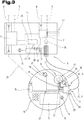
- the lighting control device 25 is structurally arranged in a machine-side coupling counterpart 19.
- Such an arrangement or embodiment of the control system 1 can be particularly advantageous in the case of cable-based signal connections 22 between the safety switching element 15 of the handheld operating device 10 and a control device 6 or safety controller 7 of the control system 1.
- Such an embodiment is also in the Fig. 3 shown, whereby in the Fig. 3
- a hand-held control unit, as well as further components of the control system 1, excerpts and in comparison to FIG Fig. 1 are shown enlarged.
- the same reference numerals or component designations are used for the same parts as in Fig. 1 and Fig. 2 used. To avoid unnecessary repetition, please refer to the detailed description of the Fig. 1 and Fig. 2 pointed out or referred to.
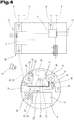
- the at least one lighting control device 25 is structurally arranged in the hand-held operating device 10.
- Such an embodiment is in the Fig. 4 illustrated, also in the Fig. 4 Again, the same reference numerals or component designations are used for the same parts as in FIGS FIGS. 1 to 3 be used.
- the one in the Fig. 4 The embodiment shown can be particularly useful in the case of a purely wireless signal connection 22 between the safety switching element 15 and a control device 6 or safety controller 7 of the control system 1.
- a power supply means 24 for the electrical power supply of the lighting device 17 can of course be arranged or integrated on or in the hand-held control device 10.
- those in the Fig. 3 and the Fig. 4 The illustrated embodiments represent alternative solutions, in particular for the configuration of the signal connection 22. It should be noted at this point, however, that the in the Fig. 3 The embodiment shown in principle also with that in FIG Fig. 4 embodiment shown can be combined.
- control system can therefore also each comprise both a lighting control device 25 in a coupling counterpart 19 and a lighting control device 25 in a handheld control device 10, in which case the control system 1 is used to select one of the lighting control devices 25 for the electrical or electronic adjustment of the visually perceptible ones Luminous intensity of the lighting device 17 can be formed.
- control system 1 is used to select one of the lighting control devices 25 for the electrical or electronic adjustment of the visually perceptible ones Luminous intensity of the lighting device 17 can be formed.
- a corresponding selection is made by an operator.
- At least one manually adjustable input setting means 26 can be functionally assigned to the at least one lighting control device 25.
- the lighting control device 25 can be designed for the electrically and / or electronically controlled adjustment of the visually perceptible light intensity of the lighting device 17 on the basis of a respective position of the input setting means 26.
- a manually adjustable input setting means 26 can be formed, for example, by a rotary or slide control functionally connected to the lighting control device 25.
- input setting means 26 in the form of plus and minus buttons or other design variants are also conceivable.
- such an input setting means 26 can be arranged on the hand-held control device 10 itself, wherein in the case of a lighting control device 25 arranged in the hand-held control device, the input setting means 26 can be functionally linked directly to the lighting control device 25. This case is exemplified in the Fig. 4 illustrated.
- an input setting means 26 placed on the hand-held operating device 10 can also, for example, be provided by a be functionally connected to the corresponding lighting control device 25 via the cable 21, as exemplified in FIG Fig. 3 is shown.
- corresponding input setting means 26 can of course also be placed in the area of a coupling counterpart 19 at a position that is as easily accessible as possible.
- the at least one lighting control device 25 for the electrically and / or electronically controlled adaptation of the visually perceptible light intensity of the lighting device 17 within a limited range between a control-technically predeterminable one or adaptable, minimum limit intensity and a control-technically predeterminable or adaptable, maximum limit intensity is formed.
- the minimum and maximum limit intensity can each be specified or stored electronically readable by the lighting control device 25, for example in a memory unit of a control device 6, 7 of the control system 1 or a memory unit of the lighting control device 25 itself.
- the lighting control device 25 is designed for the control-technical specification or adaptation of the corresponding limit intensities for the light intensity. This can take place, for example, on the basis of sensors, etc. connected to the lighting control device 25, as will be explained in more detail below.
- the control system 1 can comprise at least one detection means 27 for monitoring user activities.
- a detection means 27 is preferably arranged on or in the hand-held control device 10 itself, and can, for example, include motion sensors, position and / or acceleration sensors or a gyroscope, optical sensors, or also time measuring devices for monitoring a timeout for a non-existence of user activities, in particular of user input.
- Correspondingly configured detection means 27 can be designed to signal a detected presence or a detected non-presence of user activities to the at least one lighting control device 25.
- the at least one lighting control device 25 can, when there is a coupled signal connection 22 between the safety switching element 15 and a control device 6 or a safety controller 7, and when the presence of user activities is signaled, for the electrically and / or electronically controlled adjustment of the visually perceptible light intensity a first, low level be formed. If there is a coupled signal connection 22 and if the detection means 27 signals that there is no user activity, the lighting control device 25 can, on the other hand, be designed for the electrically and / or electronically controlled adjustment of the visually perceptible light intensity to a second level, which is higher than the first level. In the latter case, the adjustment or setting of the higher, second luminous intensity level can, if necessary, also take place after a definable period of time has elapsed or after the signaling of the absence of user activities.
- an embodiment of the control system 1 can be advantageous in which the coupling counterpart (s) 19 of a control system 1 is assigned an identifier, which identifier is data-technical information with regard to a minimum limit intensity and / or an optimal level for the visually perceptible light intensity in the area of the assigned system component 3.
- an identifier can be formed, for example, by a data identifier stored in terms of data in a memory unit of a control device 6 or safety controller 7 or in a memory unit of a lighting control device 25 assigned to the respective coupling counterpart 19.
- the lighting control device can be designed for direct detection of the identifier by reading out such an identifier from the corresponding memory unit using data technology.
- the lighting control device is designed for indirect detection of an identifier 28 via an identifier detection means 29.
- an identifier detection means 29 is formed on the handheld operating device 10, which depending on the type or design of the identifier 28, for example, as a barcode or 2D code reader, or as an RFID scanner and the like can be formed.
- an identifier 28 that can correspondingly be detected with the identifier detection means for example a bar code or 2D code, or an RFID transponder, can be attached to the end in the region of the plug connection 23 of the cable 21.
- the identifier 28 can then be read out by means of the identifier detection means 29 and transmitted, for example, via the cable 21 to the lighting control device 25 arranged in the counterpart coupling point 19.
- the lighting control device 25 can be designed for the electrically or electronically controlled adjustment of the visually perceptible light intensity on the basis of the data-related information of the identifier 28.
- the identifier 28 can also have data-technical information about the already described minimum limit intensity and / or the maximum limit intensity for the corresponding system component or coupling counterpart 19, or provide it to the lighting control device 25.
- the at least one lighting control device 25 can comprise a first switching means 30, and the lighting control device 25 can be designed to activate or deactivate the lighting device 17 by switching the first switching means 30 to an electrically conductive or a non-conductive switching state.
- a lighting control device 25 arranged in the coupling counterpart 19 is designed to open or close an electrical power supply 31 routed via the cable 21 via the first switching means 30.
- a lighting control device 25 arranged in a hand-held control device 10 can of course also be designed for opening or closing an internal power supply 31 for the lighting device 17 of the hand-held control device 10 via the first switching means 30.
- the at least one lighting control device 25 is designed to electronically adjust the visually perceptible light intensity of the lighting device 17 by applying a pulse-width-modulated control signal to the first switching means 30.
- This design variant of the lighting control device 25 allows a particularly energy-efficient, electronically controlled adaptation of the visually perceptible light intensity for lighting devices 17 suitable for this, which can have lighting means formed by light-emitting diodes or LEDs, for example.
- Such a pulse-width-modulated control signal is characterized by periodically successive pulse intervals and pause intervals.
- the lighting control device 25 switches the electrical power supply 31 conductive or closed via the first switching means 30, so that the lighting device 17 is supplied with power during a pulse interval and lights up accordingly.
- the lighting control device 25 switches the power supply 31 non-conductive or open via the first switching means 30, so that the lighting device 17 is not supplied with power during a pause interval and, accordingly, does not light up.
- the pulse-width-modulated control signal is fed into the respective electrical power supply 31 or the respective lighting device 17 via the first switching means 30, see FIG Fig. 3 or. Fig. 4 , coupled.
- the human eye perceives only the average emitted light intensity of the lighting device 17 as a visually perceptible or visually perceived light intensity.
- the human eye also does not perceive any flickering of the lighting device 17.
- the at least one lighting control device 25 for activating or deactivating the lighting device 17 comprises a second, switchable switching means 32, which second switching means 32 is electrically connected in series with the first switching means 30 is.
- the lighting control device 25 can be designed to switch both switching means 30, 32 into a non-conductive state when the signal connection 22 between the safety switching element 15 and the control device 6 or safety controller 7 is released.
- the lighting control device 25 can in principle also be designed to act on the second switching means 32 with a pulse-width-modulated control signal.
- the at least one lighting control device 25 is assigned at least one checking means 33 for checking the line state or switching state of the switching means (s) 30, 32, and the lighting control device 25 for checking if the lighting device 17 is in a deactivated state the proper non-conductive state of the switching means 30, 32 is formed by means of the at least one checking means 33.
- the checking means 33 can be formed here, for example, by a current measuring means integrated into the electrical power supply 31, by means of which it can be checked whether a lighting device 17 is being supplied with current or not.
- checking means 33 can also be used for this purpose, for example checking means 33 which directly detect a respective switching state of the switching means (s) 30, 32.
- checking means 33 which directly detect a respective switching state of the switching means (s) 30, 32.
- the checking means 33 can therefore also basically be formed by a light-sensitive sensor device. The use of such light-sensitive sensor devices or sensor means for the control system 1 is explained in more detail below.
- the at least one lighting control device 25 is designed to execute a test cycle, which test cycle alternately includes switching one of the switching means 30, 32 to a non-conductive state and the simultaneous switching of the or the other switching means 30, 32 in a conductive state. That way you can the lighting control device 25 via the checking means 33 cyclically check each individual switching means 30, 32 for its functionality, or the lighting control device 25 can check whether each of the switching means 30, 32 can be switched to a proper, non-conductive state by executing a corresponding test cycle.
- the at least one lighting control device 25 is assigned a signal connection status checking means 34 for signaling purposes, which signal connection status checking means 34 is designed to continuously check the coupling status of the signal connection 22, and that the lighting control device 25 in the event of a coupled status of the signal connection 22 for activating the lighting device 17 is formed, and in the case of a released state of the signal connection 22 is formed to deactivate the lighting device 17.
- signal connection status checking means 34 can be designed, for example, for the detection of a proper electrical current flow or test current via the signal connection 22, for example a signal connection 22 routed via the cable 21, as exemplified with the aid of FIG Fig. 3 illustrated embodiment is illustrated.
- a signal connection status checking means 34 is also conceivable, which is used to check correct signal transmission via a cable-connected signal connection 22, or as in FIG Fig. 4 is shown, is designed to check proper signal transmission via a wireless signal connection 22.
- wired signal connections 22 it is in principle also possible to establish an established or disconnected state of a wired signal connection 22 by detecting a connected or disconnected or disconnected or decoupled plug connection 23, as is also greatly simplified in FIG Fig. 3 is shown.
- a signal connection status checking means 34 can be formed here by a coupling status checking means 35, for example a magnetic or inductive sensor, or an optical sensor for detecting whether the plug connection 23 is established or disconnected, as shown in FIG Fig. 3 is shown.
- the at least one lighting control device 25 with at least a first, luminous intensity-sensitive sensor means 36 can be connected in terms of data signal technology.
- the illustrated first sensor means 36 can be arranged structurally in the vicinity of the safety switching element 15, and can be provided for detecting the ambient brightness in the vicinity of the safety switching element 15.
- a sensor means for detecting the ambient brightness can also be arranged inside the safety switching element or its jacket.
- the first sensor means 36 can be arranged on the hand-held control device 10 in such a way that a light detection direction for the first sensor means 36 is arranged pointing away from the safety switching element 15, as indicated by the arrows 37 in FIG Fig. 3 and the Fig. 4 is indicated.
- the at least one lighting control device 25 can be designed for automatic, electrical or electronic adaptation of the visually perceptible light intensity of the lighting device 17 on the basis of the detected ambient brightness.
- the lighting control device 25 can likewise be designed for the automatic, dynamic specification or adaptation of a minimum limit intensity for the lighting device 17 on the basis of the detected ambient brightness.
- the lighting control device 25 is designed, in the event of a detected increase in ambient brightness, to increase the visually perceptible light intensity of the lighting device 17 and / or to increase the default or a default value for the minimum limit intensity.
- the lighting control device 25, in the case of a detected decrease in ambient brightness via the first sensor means 36, can be designed to reduce the visually perceptible light intensity of the lighting device 17 and / or to reduce the default or a default value for the minimum limit intensity.
- the surroundings of a workstation or a system component can be illuminated or illuminated by any type of light source, although a plurality of light sources can of course also be present.
- Ambient illumination sources are also used which, due to their mode of operation, are subject to periodic fluctuations in brightness, especially when fed with AC voltage. Examples are LED lighting, mercury vapor lamps or neon tubes.
- arithmetic smoothing or filtering or arithmetic averaging takes place over a certain observation period, for example in the range of 200 ms, or over several successive measuring points. In this way, such ambient brightness fluctuations can be calculated. In this way, for example, it is possible to prevent the illuminated safety switching element from flickering as a result of the ambient brightness-dependent adaptation of the visually perceptible light intensity of the lighting device.
- a sampling frequency with which the ambient brightness is detected is significantly higher than twice the network frequency. Under no circumstances should the ambient brightness be recorded with a sampling rate that corresponds to twice the network frequency or a frequency divided as a whole number of twice the network frequency, since this could result in beat effects when the ambient brightness is recorded.
- changes in the intensity of the lighting device are always carried out slowly in terms of control technology, with a ramp-like transition in the range of a few seconds.
- This makes it possible to prevent any detected, low-frequency periodic changes in brightness in the ambient brightness, which can be caused, for example, by flashing signal lights in the vicinity, from the controlled adaptation of the light intensity to a safety switching element that can be perceived as flashing accordingly.
- uncertainties or possible confusion among perceiving persons with regard to the meaning of such an alleged light signal can be avoided.
- the first sensor means 36 can, however, also be designed or used to detect coded light signals. Like in the Fig. 4 is illustrated schematically, the control system 1 can for this purpose at least one locally assigned to a system component Include light source 44, which light source 44 is designed to emit a coded light signal.
- the first light intensity-sensitive sensor means 36 can be designed to detect and provide the encoded light signal of the light source 44 with respect to the lighting control device 25.
- the lighting control device 25 is designed to provide information about the detection of a coded light signal to a control device 6 and / or a safety controller 7, and that the respective control device 6 and / or safety controller 7 for enabling at least of observation-relevant control commands is only formed in the case of a provision of information about the detection of a coded light signal by the lighting control device 25.
- the environment of a certain machine or system component can be illuminated with a light signal with a system-specific coding.
- certain operating commands in particular control commands relevant to observation, can only be executed as long as the operator is at least within sight of the respective system component and can visually detect and monitor the effect of his operator actions.
- the at least one lighting control device 25 can additionally be line-connected to a second, luminous intensity-sensitive sensor means 38 by means of data signals, which second sensor means 38 is provided for detecting an actual value of the luminous intensity of the lighting device 17.
- the second sensor means 38 can in turn be structurally arranged in the vicinity of the safety switching element 15 on the hand-held control device 10 such that a light detection direction for the second sensor means 38 is arranged pointing to the safety switching element 15, as indicated by the arrows 39 in FIG Fig. 3 and the Fig. 4 is indicated.
- an arrangement of such a second sensor means within the safety switching element or its jacket is again possible.
- the second sensor means 38 can continuously provide an actual value of the light intensity emitted by the lighting device 17 for the lighting control device 25.
- the at least one lighting control device 25 can be designed to compare the detected actual value of the light intensity of the lighting device 17 with an internally established and / or control-generated setpoint value for the light intensity.
- a setpoint value generated by control technology can be generated, for example, on the basis of or as a function of an ambient brightness that is detected or captured by means of the first, light-sensitive sensor means 36.
- the lighting control device 25 can be designed to provide a setpoint error signal to a control device 6 and / or a safety controller 7 of the control system 1, for example on the basis of the comparison when a defined limit value for a permissible deviation of the actual value from the setpoint is exceeded.
- the lighting control device 25 can of course be used to provide the setpoint error signal both when the setpoint value is undershot and when it is exceeded. In principle, different, permissible deviations for falling below or exceeding the target value can also be defined in this context.
- the at least one lighting control device 25 can basically be designed to compare the detected actual value of the luminous intensity of the lighting device 17 with an internally defined and / or a control-generated setpoint for the luminous intensity.
- the lighting control device 25 can be designed for electrical and / or electronic readjustment of the visually perceptible light intensity of the lighting device 17. With this embodiment, for example, age-related deviations in the light intensity of the lighting device 17 can be corrected automatically or in terms of control technology by means of the lighting control device 25.
- the at least one lighting control device 25 can be designed to adapt the visually perceptible light intensity by applying a pulse-width-modulated control signal to the lighting device 17.
- the second sensor means 38 is designed to detect a time profile of the pulse-width-modulated light emitted by the lighting device 17.
- a means for checking the proper functioning of the lighting device 17 can be provided.
- the lighting control device 25 can be designed to compare a sensor signal of the second sensor means 38 detected during a pulse time interval of the pulse-width-modulated control signal with a sensor signal of the second sensor means 38 detected during a pause time interval of the pulse-width-modulated control signal.
- the lighting control device 25 can provide a pulse-pause error signal in the event of a negative check result or a negative result of the comparison, for example in the event of a discrepancy between the time profile of the pulse-width-modulated control signals and the time profile of the pulse-width-modulated light emitted by the lighting device be designed with respect to a control device 6 and / or a safety controller 7 of the control system 1.
- the at least one lighting control device 25 can also be designed to compare the sensor data provided by the first sensor means 36 and / or the second sensor means 38 with reference data that can be stored or previously stored in the control system 1.
- reference data can be stored, for example, in a memory unit of a control device 6 or a safety controller 7 of the control system 1, and can be electronically read out by the at least one lighting control device 25 when a signal connection 22 is established between the safety switching element 15 and the control device 6 or safety controller 7.
- Such reference data can, for example, also be formed by measurement data from the first and / or second sensor means 36, 38, which are provided for the lighting control device 25 during use of the hand-held control device 10 and are stored in a memory unit by the lighting control device 25. If a permissible deviation of the sensor data from the reference data is exceeded, the lighting control device 25 can be designed to provide a deviation error signal for a control device 6 and / or a safety controller 7 of the control system 1.
- the at least one lighting control device 25 can also comprise a current measuring means 40 for determining the electrical current flow picked up by the lighting device 17, as shown in FIG Fig. 3 and the Fig. 4 is illustrated.
- a current measuring means 40 can be formed, for example, by a measuring transducer which provides a measured value for the lighting control device 25 in terms of signals or data.
- the lighting control device 25 can subsequently be designed to compare the recorded current flow measurement data with reference data stored in a memory unit of the control system 1. If a predetermined deviation of the specific current flow data from the stored reference data is exceeded, the lighting control device 25 can then be designed to provide a current flow error signal to a control device 6 and / or a safety controller 7 of the control system 1.
- the corresponding control device 6 or the corresponding safety controller 7 can immediately transfer the system 2 or the affected system component 3 be designed in a safe state.
- a loss of safety in the system for example due to defects in the lighting device 17 with the increased risk of a person making a mistake about the effectiveness of the safety switching element in a possible emergency, can be prevented until, for example, a necessary maintenance or repair measure has been carried out.
- control device 6 and / or the safety controller 7 are designed for the signaling coupling of an error signal provided by the lighting control device 25 in a signal-equivalent manner to a manually operated safety switching element 15 in a safety circuit 41 for the system 2 or the system component 3 is how this is greatly simplified and also schematically in the Fig. 3 and the Fig. 4 is shown.
- the corresponding control device 6 or the corresponding safety controller 7 can be used when an error signal is provided by the lighting control device 25, however, can also be designed, for example, to block safety-relevant control commands, in particular by deactivating an approval signal from an approval button integrated in the hand-held control device, and / or, for example, to display the error signal or signals.
- FIG. 5 a further and possibly independent embodiment of the control system 1 is shown, again with the same reference numerals or component designations as in the preceding for the same parts FIGS. 1 to 4 be used.
- the control system 1 again with the same reference numerals or component designations as in the preceding for the same parts FIGS. 1 to 4 be used.
- the one in the Fig. 5 The embodiment variant shown can be advantageous when the at least one lighting control device 25 is configured to apply a pulse-width-modulated control signal to the lighting device 17.
- the first sensor means 36 and the second sensor means 38 have a common intensity detection element 42, and that the at least one lighting control device 25 for periodically interrogating the intensity detection element 42 during pulse time intervals and pause time intervals of a pulse-width-modulated control signal for the lighting device 17 is trained.
- the first sensor means 36 and the second sensor means 38 can be structurally essentially formed by a sensor means or a sensor device, which is arranged in a close range with its light detection direction - indicated by arrow 43 - aligned in the direction of the safety switching element 15.
- the distinction between the first sensor means 36 provided for detecting the ambient brightness and the second sensor means 38 provided for detecting an actual value of the luminous intensity of the lighting device is in this case given or by the specific temporally successive interrogation of the common intensity detection element 42 by the lighting control device 25 .
- the lighting control device 25 can make a corresponding, sequential query that is offset in time of the common intensity detection element 42 may be formed.
- the first and second sensor means can therefore also be referred to or understood as virtual first sensor means 36 and virtual second sensor means 38 in this case.
- the at least one lighting control device 25 can be designed to determine the ambient brightness from the sensor data queried during pause time intervals, since during the pause time intervals of the pulse-width-modulated control signal the lighting device 17 is not supplied with energy or electrical current and therefore does not light up.
- FIGS. 2 to 5 illustrated embodiments a further, possibly independent embodiment may also be useful, which in the Fig. 6 is shown. It will be in the Fig. 6 again for the same parts the same reference numerals or component designations as in the preceding Fig. 1 to Fig. 5 used. In order to avoid unnecessary repetition, please refer to the detailed description in the preceding section Figs. 1 to 5 pointed out or referred to.
- the first sensor means 36 and the second sensor means 38 or the common intensity detection element 42 can be structurally arranged within the jacket 16 of the safety switching element 15. In particular, this represents a structurally particularly efficient and space-saving embodiment of the hand-held operating device 10.
- the light intensity of the lighting device 17 and also the ambient brightness can in principle be detected either directly by sensor means 36, 38 arranged inside the safety switching element 15 or its jacket 16, or by sensor means or sensor devices arranged outside after passing through the semitransparent jacket 16 of the safety switching element 15 are recorded.
- the respective detected light intensity of the lighting device 17 can be determined by appropriate, computational adaptation or computational Conversion of the corresponding recorded or measured light intensities into arithmetically well usable, in particular digital values are scaled or arithmetically adapted.
- computational calibration methods can optionally also be used for compensation.
- a respective ambient brightness can of course also be detected in principle by a sensor means 36 arranged within the semitransparent casing 16 of the safety switching element 15.
- a sensor means 36 arranged within the semitransparent casing 16 of the safety switching element 15.
- the brightness measured through the jacket by means of a sensor means 36 or an intensity detection element 42 which may differ from the actual ambient brightness due to absorption and / or light scattering effects and the like, can be correspondingly adjusted or corrected by calculation, for example again by using computational calibration methods or the like.
- the lighting device 17 can have a plurality of differently colored lighting means 18.
- the at least one lighting control device 25 can be designed for separate, electrically and / or electronically controlled adaptation of the individual lighting means 18, as is also the case in FIG Fig. 6 is illustrated schematically.
- the at least one lighting control device 25, in the case of an actuated safety switching element 15, is designed for electrically or electronically controlled adaptation of the lighting device 17 or the individual lighting means 18 by means of a display signal, in particular by a visually perceptible flashing signal.
- a display signal in particular by a visually perceptible flashing signal.
Description
Die Erfindung betrifft ein Steuerungssystem für elektrisch gesteuerte Anlagen.The invention relates to a control system for electrically controlled systems.
In der industriellen Praxis ist es üblich, Produktionsabläufe oder Fertigungsprozesse und Dergleichen mittels einer oder mehrerer voll- und/oder halbautomatisch gesteuerter Maschine(n), welche zum Teil in ausgedehnten Anlagen mit einer Vielzahl an Anlagenkomponenten zusammengefasst sein können, auszuführen. Hierbei umfassen diese Prozesse zum Beispiel oftmals Abläufe bzw. Bewegungen, bei welchen beteiligte Massen, Energien, Kräfte, Temperaturen, Strahlungen, Stoffe, etc. grundsätzlich zu einer Gefährdung für die Gesundheit oder sogar das Leben von Menschen führen können. Dies gilt meist insbesondere im Falle des Eintretens ungewöhnlicher bzw. nicht ordnungsgemäßer Ausnahmesituationen oder Fehlerfälle.In industrial practice, it is customary to carry out production processes or manufacturing processes and the like by means of one or more fully and / or semi-automatically controlled machine (s), some of which can be combined in extensive systems with a large number of system components. These processes often include, for example, sequences or movements in which the masses, energies, forces, temperatures, radiation, substances, etc. involved can in principle lead to a risk to the health or even the life of people. This usually applies in particular in the event of unusual or improper exceptional situations or errors.
Daher ist es zweckmäßig und auch geläufig bzw. vorgeschrieben, im Umfeld bzw. im Bereich von Anlagenkomponenten bzw. Maschinen oder Maschinenteilen an leicht zugänglichen und einzusehenden Stellen manuell betätigbare Sicherheitsschaltelemente anzuordnen, um Bedienpersonen ein möglichst rasches Reagieren auf Gefahrensituationen zur eindeutigen Beendigung einer Gefahrensituation zu ermöglichen. Bei manueller Betätigung solcher Sicherheitsschaltelemente kann eine Anlage oder Anlagenkomponente bzw. Maschine in einen sicheren Zustand versetzt werden. Je nach Typ bzw. Ausgestaltung einer jeweiligen Anlage bzw. Anlagenkomponente kann eine Versetzung in einen sicheren Zustand bzw. Betriebszustand etwa durch Abschalten von Antriebsvorrichtungen bzw. Aktuatoren, Unterbrechen der Energiezufuhr, Aktivieren von Bremsvorrichtungen oder ähnlichen Maßnahmen bewerkstelligt werden.Therefore, it is expedient and also common or prescribed to arrange manually operated safety switching elements in easily accessible and visible places in the vicinity or in the area of system components or machines or machine parts in order to enable operators to react as quickly as possible to dangerous situations in order to clearly end a dangerous situation . When such safety switching elements are operated manually, a system or system component or machine can be put into a safe state. Depending on the type or configuration of a particular system or system component, a transfer to a safe state or operating state can be achieved, for example, by switching off drive devices or actuators, interrupting the energy supply, activating braking devices or similar measures.
Derartige Sicherheitsschaltelemente umfassen zum Beispiel die bekannten, pilzförmig ausgestalteten Not-Aus- bzw. Not-Halt-Schalter. Um solche Sicherheitsschaltelemente eindeutig und zweifelsfrei identifizieren zu können, sind in einschlägigen Normen spezifische, farbliche Kennzeichnungen hierfür vorgeschlagen, bzw. in vielen Fällen vorgeschrieben. Hierdurch ist beispielsweise ein Not-Aus-Schalter auch für Personen, welche zur Bedienung einer Anlage oder Anlagenkomponente nicht spezifisch geschult sind, ein entsprechend farblich gekennzeichneter Not-Aus-Schalter sowie dessen Wirkung dennoch eindeutig erkennbar bzw. geläufig.Such safety switching elements include, for example, the known mushroom-shaped emergency stop or emergency stop switches. In order to be able to identify such safety switching elements unambiguously and unequivocally, specific, colored markings are proposed in the relevant standards, or in many cases are prescribed. As a result, for example, an emergency stop switch is also clearly recognizable or familiar to people who are not specifically trained to operate a system or system component, and an emergency stop switch marked in a corresponding color, as well as its effect.
Obwohl in der industriellen Fertigung die Prozesse und Abläufe größtenteils automatisiert von funktionalen, elektronischen Steuerungsvorrichtungen, welche funktionswirksam auf elektrisch steuerbare Komponenten einer Anlage einwirken können, vorgenommen werden, ist für bestimmte Abläufe bzw. Aufgaben eine manuelle Bedienung bzw. Steuerung durch eine menschliche Bedienperson zweckmäßig bzw. erforderlich. Beispiele hierfür sind etwa die Vornahme von Einstellungen oder eines Werkzeugwechsels, Behebung von Betriebsstörungen oder - fehlem, oder das sogenannte Teachen von Robotern.Although the processes and procedures in industrial production are largely automated by functional, electronic control devices that can function effectively on electrically controllable components of a system, manual operation or control by a human operator is appropriate or appropriate for certain processes or tasks .required. Examples of this are, for example, making settings or changing tools, correcting malfunctions or faults, or teaching robots.
Heutzutage werden für Abläufe bzw. Aufgaben, welche die manuelle Eingabe von Steuerungskommandos durch eine menschliche Bedienperson erfordern, häufig mobile bzw. transportable Bediengeräte verwendet. Solche mobilen Handbediengeräte erlauben einer Bedienperson eine gewisse Beweglichkeit im Bereich einer Anlage bzw. Maschine. Von Vorteil ist dabei, dass die Bedienperson während der manuellen Bedienung eine geeignete bzw. günstige Beobachtungsposition im Bereich einer Maschine einnehmen kann.Nowadays, mobile or transportable operating devices are often used for processes or tasks which require the manual input of control commands by a human operator. Such mobile handheld operating devices allow an operator a certain degree of mobility in the area of a system or machine. The advantage here is that the operator can take a suitable or favorable observation position in the area of a machine during manual operation.
Grundsätzlich können derartige, mobile Handbediengeräte zur Bereitstellung bzw. Übertragung von Daten, Signalen und Steuerungskommandos über drahtgebundene oder drahtlose Kommunikationsverbindungen mit einer oder mehreren funktionalen Steuerungsvorrichtungen einer elektrisch steuerbaren Anlage und/oder Anlagenkomponente verbunden sein. Die Eingabe von Steuerungskommandos an einem solchen signal- und datentechnisch gekoppelten Handbediengerät kann über entsprechende Kommunikationsverbindungen an eine Steuerungsvorrichtung übertragen werden, welche Steuerungsvorrichtung sodann die übertragenen bzw. bereitgestellten Steuerungskommandos umgehend in entsprechende Steuerungssignale für Aktuatoren, Antriebe, Heiz- oder Kühlmittel, oder sonstige elektrisch steuerbare Maschinenkomponenten umsetzt. In sicherheitstechnischer Hinsicht ist in diesem Zusammenhang von großen Vorteil, wenn auch an einem Handbediengerät zumindest ein Sicherheitsschaltelement, beispielsweise in der Art eines Not-Aus- bzw. Not-Halt-Schalters vorgesehen ist.In principle, such mobile handheld operating devices for the provision or transmission of data, signals and control commands can be connected to one or more functional control devices of an electrically controllable system and / or system component via wired or wireless communication links. The input of control commands on such a handheld control unit, which is coupled in terms of signaling and data technology, can be transmitted via appropriate communication links to a control device, which control device then immediately converts the transmitted or provided control commands into corresponding control signals for actuators, drives, heating or cooling means, or other electrically controllable ones Implements machine components. In terms of safety, it is of great advantage in this context if at least one safety switching element, for example in the form of an emergency stop or emergency stop switch, is also provided on a hand-held control device.
Während fix bzw. permanent mit einer bestimmten Anlagenkomponente bzw. Maschine verbundene Handbediengeräte durchaus üblich sind, geht der Trend in der heutigen, industriellen Praxis vermehrt in Richtung variabler bzw. temporärer Zuordnung eines Handbediengeräts zu einer Anagenkomponente oder Maschine. In anderen Worten ausgedrückt wird vermehrt der Wunsch geäußert, ein Handbediengerät nur während jener Zeit steuerungstechnisch, insbesondere für die manuelle Eingabe von Steuerungskommandos mit einer funktionalen Steuerungsvorrichtung zu verbinden bzw. zu koppeln, in welcher Zeit manuelle Bedienhandlungen auch tatsächlich vorgenommen werden. Dies zumal auch deshalb, da im ordnungsgemäßen bzw. störungsfreien Automatikbetrieb einer Anlage bzw. Anlagenkomponente die Ankoppelung eines Handbediengerätes zur manuellen Bereitstellung von Steuerungskommandos nicht erforderlich ist. Im ordnungsgemäßen Automatikbetrieb kann eine Kommunikationsverbindung für die Übertragung bzw. Bereitstellung von manuell eingegebenen Steuerungskommandos daher aufgehoben werden, etwa durch Abstecken einer entsprechenden Kabelverbindung oder durch Unterbrechen einer entsprechenden kabellosen Funkverbindung oder auch durch Aufheben einer datentechnischen Kopplung in einem Kommunikationsnetzwerk. Hierdurch können auch potentielle Gefahren durch eine mögliche Fehlbedienung hintangehalten werden, etwa wenn eine Bedienperson ein Eingabeelement zum Auslösen eines Steuerungskommandos am Handbediengerät versehentlich betätigt, ohne sich im Nahbereich der entsprechenden Anlagenkomponente bzw. Maschine aufzuhalten.While manual control devices connected permanently or permanently to a certain system component or machine are quite common, the trend in today's industrial practice is increasingly towards variable or temporary assignment of a manual control device to a system component or machine. In other words, it is increasing Expressed a wish to connect or couple a manual control device to a functional control device only during the time during which manual control actions are actually carried out, in particular for the manual input of control commands. This is also because in the proper or trouble-free automatic operation of a system or system component, the coupling of a manual control device for the manual provision of control commands is not necessary. In proper automatic operation, a communication connection for the transmission or provision of manually entered control commands can therefore be canceled, for example by unplugging a corresponding cable connection or by interrupting a corresponding wireless radio connection or by canceling a data link in a communication network. This also prevents potential dangers from possible incorrect operation, for example if an operator inadvertently actuates an input element to trigger a control command on the hand-held operating device without being in the vicinity of the corresponding system component or machine.
Durch die lediglich temporäre, steuerungstechnische Wirkverbindung derartiger Handbediengeräte mit funktionalen Steuerungsvorrichtungen einer Anlage, ist aber auch eine unmittelbare Funktion von an dem Handbediengerät angeordneten Sicherheitsschaltelementen nur temporär gegeben. Insbesondere bei im Bereich einer Anlagenkomponente abgelegten Handbediengeräten ist für eine Bedienperson oder auch für nicht zur Bedienung der Anlage oder Anlagenkomponente bzw. Maschine vorgesehenen Drittpersonen oftmals nicht sofort bzw. unmittelbar ersichtlich, ob ein Handbediengerät mit einer Steuerungsvorrichtung der Anlage steuerungstechnisch kommunikationsverbunden ist, bzw. ob ein Sicherheitsschaltelement am Handbediengerät funktionswirksam betätigt werden kann. Als Abhilfe werden oftmals organisatorische Maßnahmen vorgeschrieben, gemäß derer ein nicht funktionswirksames Handbediengerät beispielsweise wegzuräumen bzw. aus dem Sichtbereich zu verbringen ist. In der Praxis werden solche organisatorischen Maßnahmen erfahrungsgemäß nur unvollständig umgesetzt. Folglich kann es grundsätzlich zu einem Irrtum betreffend die Funktionswirksamkeit eines an einem Handbediengerätes angeordneten Sicherheitsschaltelements kommen. Bei Auftreten einer akuten Gefahrensituation kann es in weiterer Folge bei einem Versuch der Beendigung der Gefahrensituation durch wirkungsloses Betätigen, beispielsweise eines Not-Halt-Sicherheitsschaltelements am Handbediengerät, zu einem Verstreichen wertvoller Zeit kommen.Due to the merely temporary, control-related operative connection of such hand-held operating devices with functional control devices of a system, however, a direct function of the safety switching elements arranged on the hand-held operating device is only given temporarily. In particular in the case of hand-held operating devices stored in the area of a system component, it is often not immediately or immediately apparent to an operator or to third parties not intended to operate the system or system component or machine whether a hand-held operating device is connected in terms of control technology to a control device of the system, or whether a safety switching element on the hand-held control unit can be operated effectively. As a remedy, organizational measures are often prescribed according to which a non-functional hand-held control device, for example, has to be cleared away or moved out of the field of vision. In practice, experience has shown that such organizational measures are only implemented incompletely. As a result, there can in principle be an error relating to the functional effectiveness of a safety switching element arranged on a hand-held operating device. In the event of an acute dangerous situation, it can subsequently be the case when an attempt is made to end the dangerous situation by ineffective actuation, for example of an emergency stop safety switching element on the handheld control unit, valuable time has passed.
In sicherheitstechnischer Hinsicht ist es daher unbedingt wünschenswert, dass für eine Bedienperson oder auch für Dritte die Funktionswirksamkeit respektive die Wirkungslosigkeit eines Sicherheitsschaltelements an einem Handbediengerät möglichst deutlich und unmissverständlich ersichtlich ist.In terms of safety, it is therefore absolutely desirable that the functional effectiveness or the ineffectiveness of a safety switching element on a hand-held control device is as clearly and unambiguously as possible for an operator or also for third parties.
Aus dem Stand der Technik sind beleuchtete Not-Aus-Schalter mit lichtdurchlässigen bzw. semitransparenten Mantelflächen bekannt, bei welchen durch dem Not-Aus-Schalter zugeordnete, insbesondere durch in dem Not-Aus-Schalter integrierte Leuchtmittel der entsprechende Not-Aus-Schalter farblich kenntlich gemacht wird. In der
Bei Anwendung von solchen aktiv beleuchteten Sicherheitsschaltelementen ergeben sich in der industriellen Praxis jedoch Problemstellungen, welche vom Stand der Technik bisher nicht berücksichtigt wurden. Insbesondere ist bei aktiv beleuchteten Sicherheitsschaltelementen mit konstanter Leuchtintensität die visuell wahrnehmbare bzw. visuell empfundene Helligkeitswahrnehmung und die farbliche Wahrnehmung durch menschliche Personen sehr stark von der jeweils vorherrschenden Umgebungshelligkeit abhängig. Deshalb kann bei aktiv mit gleichbleibender Leuchtintensität beleuchteten Sicherheitsschaltelementen nicht mit ausreichender Sicherheit gewährleistet werden, dass die Funktionswirksamkeit oder die Wirkungslosigkeit eines Sicherheitsschaltelementes bei wechselnden Umgebungshelligkeiten immer zuverlässig und eindeutig für menschliche Personen erkennbar ist und gleichzeitig eine ergonomische und insbesondere blendwirkungsfreie Verwendung der Handbediengeräte ermöglicht ist.When using such actively illuminated safety switching elements, however, problems arise in industrial practice which have not been taken into account by the prior art up to now. In particular, in the case of actively illuminated safety switching elements with constant light intensity, the visually perceptible or visually perceived brightness perception and the color perception by human beings are very dependent on the prevailing ambient brightness. Therefore, with safety switching elements actively illuminated with constant light intensity, it cannot be guaranteed with sufficient certainty that the functional effectiveness or the ineffectiveness of a safety switching element is always reliably and clearly recognizable for human beings in the event of changing ambient brightness and at the same time an ergonomic and, in particular, glare-free use of the hand-held control devices is made possible.
Des Weiteren kann insbesondere bei drahtlos datengekoppelten, Akku-betriebenen Handbediengeräten ein hoher Stromverbrauch resultieren, durch welchen die Funktionszeit eines Handbediengeräts reduziert werden kann. Dies auch deshalb, da beleuchtete Not-Aus-Schalter für eine zuverlässige Wahrnehmbarkeit auch bei hoher Umgebungshelligkeit, mit ausreichender, vergleichsweise starker Leuchtintensität beleuchtet werden müssen.Furthermore, particularly in the case of wireless, data-coupled, battery-operated hand-held control devices, a high power consumption can result, through which the operating time of a hand-held control device can be reduced. This is also because illuminated emergency stop switches must be illuminated with sufficient, comparatively strong light intensity for reliable perceptibility even in high ambient brightness.
Die Dokumente
Aufgabe der Erfindung war es, die bestehenden Probleme zu lösen, und ein verbessertes Steuerungssystem zur Verfügung zu stellen, durch welches insbesondere die umgebungshelligkeitsabhängige Wahrnehmung aktiv beleuchteter Sicherheitsschaltelemente durch menschliche Personen berücksichtigt ist.The object of the invention was to solve the existing problems and to provide an improved control system by means of which, in particular, the ambient brightness-dependent perception of actively illuminated safety switching elements by human beings is taken into account.
Diese Aufgabe wird durch ein Steuerungssystem gemäß den Ansprüchen gelöst.This object is achieved by a control system according to the claims.
Es wird ein Steuerungssystem für elektrisch gesteuerte Anlagen bereitgestellt, welches wenigstens eine Steuerungsvorrichtung zur Überwachung und/oder Steuerung der Anlage und/oder von Anlagenkomponenten umfasst.A control system for electrically controlled systems is provided which comprises at least one control device for monitoring and / or controlling the system and / or system components.
Des Weiteren umfasst das Steuerungssystem zumindest ein tragbares, mobiles Handbediengerät zur Anzeige von Informationen und zur Eingabe von Steuerungskommandos durch eine Bedienperson, wobei das Handbediengerät wenigstens ein manuell betätigbares Sicherheitsschaltelement aufweist, welchem Sicherheitsschaltelement eine Beleuchtungsvorrichtung mit wenigstens einem Leuchtmittel zugeordnet ist.Furthermore, the control system comprises at least one portable, mobile handheld control device for displaying information and for inputting control commands by an operator, the handheld control device having at least one manually operable safety switching element, to which a lighting device with at least one lamp is assigned.
Das Steuerungssystem umfasst außerdem eine koppelbare und lösbare Signalverbindung zwischen dem Sicherheitsschaltelement des Handbediengeräts und der wenigstens einen Steuerungsvorrichtung oder einer separat ausgebildeten Sicherheitssteuerung, wobei das Steuerungssystem bei Vorliegen einer gekoppelten Signalverbindung und bei manueller Betätigung des Sicherheitsschaltelements zur Überführung der Anlage oder einer oder mehrerer Anlagenkomponenten in einen sicheren Zustand ausgebildet ist, und wobei das Steuerungssystem bei Vorliegen einer gekoppelten Signalverbindung zur Aktivierung der Beleuchtungsvorrichtung ausgebildet ist, und bei Vorliegen einer gelösten Signalverbindung zur Deaktivierung der Beleuchtungsvorrichtung ausgebildet ist.The control system also includes a couplable and detachable signal connection between the safety switching element of the handheld control unit and the at least one control device or a separately designed safety controller, the control system in the presence of a coupled signal connection and manual actuation of the safety switching element for transferring the system or one or more system components into one safe state is formed, and wherein the control system is formed in the presence of a coupled signal connection to activate the lighting device, and in the presence of a released signal connection is formed to deactivate the lighting device.
Wesentlich ist, dass das Steuerungssystem zumindest eine Beleuchtungssteuerungsvorrichtung umfasst, welche bei Vorliegen einer gekoppelten Signalverbindung zwischen dem Sicherheitsschaltelement des Handbediengeräts und der wenigstens einen Steuerungsvorrichtung oder der Sicherheitssteuerung zur elektrisch und/oder elektronisch gesteuerten Anpassung einer visuell wahrnehmbaren Leuchtintensität der Beleuchtungsvorrichtung ausgebildet ist.It is essential that the control system comprises at least one lighting control device which, when there is a coupled signal connection between the safety switching element of the hand-held control device and the at least one control device or the safety controller, is designed for the electrically and / or electronically controlled adjustment of a visually perceptible light intensity of the lighting device.
Hierbei ist es durchaus möglich, dass das Steuerungssystem mehrere Beleuchtungssteuerungsvorrichtungen umfasst, welche jeweils nach einer erfolgten Koppelung bzw. Herstellung einer Signalverbindung zwischen dem Sicherheitsschaltelement eines Handbediengeräts und einer Steuerungsvorrichtung des Steuerungssystems, zur Anpassung der visuell wahrnehmbaren Leuchtintensität der Beleuchtungsvorrichtung des Handbediengerätes ausgebildet sind.It is entirely possible that the control system comprises several lighting control devices, each of which is designed to adapt the visually perceptible light intensity of the lighting device of the handheld device after a coupling or production of a signal connection between the safety switching element of a handheld device and a control device of the control system.
Durch die angegebenen Merkmale ist ein technisches Mittel bereitgestellt, mittels welchem die visuell wahrnehmbare Leuchtintensität eines Sicherheitsschaltelementes grundsätzlich verändert werden kann, und insbesondere die visuell wahrnehmbare Leuchtintensität an jeweils vorherrschende Lichtverhältnisse bzw. an eine jeweilige Umgebungshelligkeit angepasst werden kann. Damit kann auch gewährleistet werden, dass die farbliche Kennzeichnung des Sicherheitsschaltelementes bei Vorliegen der gekoppelten Signalverbindung zwischen dem Sicherheitsschaltelement und der wenigstens einen Steuerungsvorrichtung, durch menschliche Personen, insbesondere Bedienpersonen zuverlässig wahrnehmbar ist.The specified features provide a technical means by which the visually perceptible light intensity of a safety switching element can be fundamentally changed, and in particular the visually perceptible light intensity can be adapted to the prevailing light conditions or to a respective ambient brightness. This can also ensure that the color coding of the safety switching element can be reliably perceived by human persons, in particular operators, when the coupled signal connection is present between the safety switching element and the at least one control device.
Dadurch kann zum Beispiel hintangehalten werden, dass ein beleuchtetes Sicherheitsschaltelement bei hoher Umgebungshelligkeit, etwa bei gut ausgeleuchteten Arbeitsplätzen oder bei starker Sonneneinstrahlung, schlecht oder nicht mehr als funktionswirksam erkennbar ist.In this way, it can be prevented, for example, that an illuminated safety switching element is poorly or no longer recognizable as functionally effective in high ambient brightness, for example in well-lit workplaces or in strong sunlight.
Andererseits kann vermieden werden, dass für eine menschliche Bedienperson bei Arbeitsplätzen bzw. Anlagenkomponenten mit niedriger Umgebungshelligkeit bzw. schwacher Beleuchtung, etwa in einer Lackiereinrichtung, eine erhebliche Blendwirkung auftritt. Etwaige nachteilige Auswirkungen hinsichtlich der manuellen Bedienbarkeit einer derartigen, schwach beleuchteten Anlagenkomponente können so hintangehalten werden. Von großem Vorteil ist ein solches Steuerungssystem insbesondere für den Einsatz in ausgedehnten Arbeitsumgebungen bzw. Anlagen mit örtlich stark wechselnden Beleuchtungsverhältnissen.On the other hand, it can be avoided that a significant glare effect occurs for a human operator at workplaces or system components with low ambient brightness or weak lighting, for example in a painting facility. Any negative effects with regard to the manual operability of such a weakly lit system component can thus be prevented. Such a control system is of great advantage especially for use in extensive work environments or systems with locally strongly changing lighting conditions.
Die Signalverbindung zwischen dem wenigstens einen Sicherheitsschaltelement des Handbediengerätes und der wenigstens einen Steuerungsvorrichtung kann grundsätzlich sowohl kabelgebunden oder drahtlos ausgeführt sein.The signal connection between the at least one safety switching element of the hand-held operating device and the at least one control device can in principle be implemented either in a wired or wireless manner.
Zusätzlich ist durch die angegebenen Merkmale ein energieeffizienter Betrieb, insbesondere von Akku-betriebenen Handbediengeräten ermöglicht. Im Besonderen bei drahtlos daten- bzw. signalgekoppelten Handbediengeräten ist mit der Möglichkeit der Anpassung bzw. Reduktion der Leuchtintensität an ein in der jeweiligen Situation angemessenes bzw. notwendiges Maß, auch der Energieverbrauch auf ein notwendiges Maß beschränkbar und kann damit die Akku-Laufzeit bzw. die Funktionslaufzeit des Handbediengerätes vorteilhafterweise angehoben werden.In addition, the specified features enable energy-efficient operation, especially of battery-operated handheld devices. In particular in the case of wireless data or signal-coupled handheld control units, with the option of adapting or reducing the light intensity to an appropriate or necessary level in the respective situation, the energy consumption can also be limited to a necessary level and thus the battery life or battery life can be reduced. the functional runtime of the hand-held control device can advantageously be increased.
Bei einer Weiterbildung kann vorgesehen sein, dass der zumindest einen Beleuchtungssteuerungsvorrichtung wenigstens ein manuell verstellbares Eingabestellmittel funktionswirksam zugeordnet ist, wobei die Beleuchtungssteuerungsvorrichtung bei Vorliegen einer gekoppelten Signalverbindung zwischen dem Sicherheitsschaltelement und der wenigstens einen Steuerungsvorrichtung und bei Verstellung des Eingabestellmittels durch eine Bedienperson zur elektrisch und/oder elektronisch gesteuerten Anpassung der visuell wahrnehmbaren Leuchtintensität der Beleuchtungsvorrichtung auf Basis der jeweiligen Stellung des Eingabestellmittels ausgebildet ist.In a development it can be provided that at least one manually adjustable input setting means is functionally assigned to the at least one lighting control device, the lighting control device for electrical and / or electrical purposes when there is a coupled signal connection between the safety switching element and the at least one control device and when the input setting means is adjusted by an operator electronically controlled adaptation of the visually perceptible light intensity of the lighting device is formed on the basis of the respective position of the input setting means.
Damit kann eine Bedienperson die visuell wahrnehmbare Leuchtintensität der Beleuchtungsvorrichtung und damit des Sicherheitsschaltelementes selbsttätig und entsprechend den jeweiligen individuellen Bedürfnissen der Bedienperson anpassen bzw. einstellen.In this way, an operator can adapt or set the visually perceptible light intensity of the lighting device and thus of the safety switching element automatically and in accordance with the respective individual needs of the operator.
Es ist erfindungsgemäß vorgesehen, dass die zumindest eine Beleuchtungssteuerungsvorrichtung zur elektrisch und/oder elektronisch gesteuerten Anpassung der visuell wahrnehmbaren Leuchtintensität der Beleuchtungsvorrichtung innerhalb eines beschränkten Bereiches zwischen einer steuerungstechnisch vorgebbaren, minimalen Grenzintensität und einer steuerungstechnisch vorgebbaren, maximalen Grenzintensität ausgebildet ist.It is provided according to the invention that the at least one lighting control device is designed for the electrically and / or electronically controlled adaptation of the visually perceptible light intensity of the lighting device within a restricted range between a control-technically specifiable, minimum limit intensity and a control-technically specifiable, maximum limit intensity.
Durch die minimale Grenzintensität ist eine visuell wahrnehmbare Mindestleuchtintensität vorgebbar, durch welche für eine zu erwartende Umgebungshelligkeit im Bereich einer bestimmten Anlagenkomponente bzw. an einem bestimmten Arbeitsplatz eine hinreichend sichere Wahrnehmung eines funktionswirksamen Sicherheitsschaltelementes ermöglicht ist. Durch die maximale Grenzintensität ist andererseits eine maximal einstellbare, visuell wahrnehmbare Leuchtintensität vorgebbar, durch welche für beleuchtungssensitive Arbeitsplätze, wie zum Beispiel Lackierkammern oder Dergleichen die Leuchtintensität beschränkt werden kann.The minimum limit intensity allows a visually perceptible minimum luminous intensity to be specified, by means of which a functionally effective safety switching element is made possible for an expected ambient brightness in the area of a certain system component or at a certain workstation. On the other hand, through the maximum limit intensity, a maximum adjustable, visually perceptible light intensity can be specified, by means of which the light intensity can be limited for lighting-sensitive workplaces, such as paint shops or the like.
Die jeweiligen minimalen und/oder maximalen Grenzintensitäten können hierbei bei ausgedehnten Anlagen mit unterschiedlichen Umgebungshelligkeiten im Bereich der Anlagenkomponenten jeweils entsprechend anpassbar sein. Auf diese Weise ist außerdem eine manuelle Verstellung bzw. Anpassung der visuell wahrnehmbaren Leuchtintensität durch eine Bedienperson nur in dem beschränkten Bereich möglich, wodurch beispielsweise ungeeignete oder fehlerhafte bzw. zu niedrige oder zu hohe Leuchtintensitätseinstellungen hintangehalten werden können. Insbesondere kann so eine Beschädigung bzw. eine Verkürzung der Lebensdauer des oder der Leuchtmittel(s) der Beleuchtungsvorrichtung durch Einstellung zu hoher visuell wahrnehmbarer Leuchtintensitäten hintangehalten werden.The respective minimum and / or maximum limit intensities can be adapted accordingly in the case of extensive systems with different ambient light levels in the area of the system components. In this way, a manual adjustment or adaptation of the visually perceptible light intensity by an operator is only possible in the restricted area, whereby, for example, unsuitable or incorrect or too low or too high light intensity settings can be prevented. In particular, damage or a shortening of the service life of the lamp (s) of the lighting device can be prevented by setting too high visually perceptible luminous intensities.
Bei einer weiteren Ausgestaltungsform kann vorgesehen sein, dass zumindest ein Erfassungsmittel zur Überwachung von Benutzeraktivitäten vorgesehen ist, welches Erfassungsmittel zur Signalisierung eines erfassten Vorliegens oder eines erfassten Nichtvorliegens von Benutzeraktivitäten gegenüber der zumindest einen Beleuchtungssteuerungsvorrichtung ausgebildet ist.In a further embodiment, it can be provided that at least one detection means is provided for monitoring user activities, which detection means is designed to signal a detected presence or a detected non-presence of user activities with respect to the at least one lighting control device.
Dadurch ist ein Mittel bereitgestellt, mittels welchem festgestellt werden kann, ob ein Handbediengerät benutzt wird oder nicht benutzt wird. Durch Bereitstellung für bzw. Signalisierung dieser Information gegenüber der Beleuchtungssteuerungsvorrichtung, kann die Anpassung der Leuchtintensität der Beleuchtungsvorrichtung dementsprechend angepasst werden.This provides a means by means of which it can be determined whether a hand-held control device is being used or not. By providing or signaling this information to the lighting control device, the adaptation of the light intensity of the lighting device can be adapted accordingly.
Beispielsweise kann eine Ausführungsform sinnvoll sein, bei welcher die zumindest eine Beleuchtungssteuerungsvorrichtung bei Vorliegen einer gekoppelten Signalverbindung und bei einer Signalisierung eines Vorliegens von Benutzeraktivitäten zur elektrisch und/oder elektronisch gesteuerten Anpassung der visuell wahrnehmbaren Leuchtintensität auf einen erstes, niedriges Niveau ausgebildet ist, und bei Vorliegen einer gekoppelten Signalverbindung und bei einer Signalisierung eines Nichtvorliegens von Benutzeraktivitäten zur elektrisch und/oder elektronisch gesteuerten Anpassung der visuell wahrnehmbaren Leuchtintensität auf ein zweites, im Vergleich zum ersten Niveau, höheres Niveau ausgebildet ist.For example, an embodiment can be useful in which the at least one lighting control device is present when a coupled signal connection is present and when a signaling of the presence of user activities for the electrically and / or electronically controlled adjustment of the visually perceptible light intensity to a first, low level, and if there is a coupled signal connection and if there is a signaling of the absence of user activities for the electrically and / or electronically controlled adjustment of the visually perceptible light intensity is formed on a second, higher level compared to the first level.
Auf diese Weise kann die visuell empfundene Leuchtintensität der Beleuchtungsvorrichtung bzw. des wenigstens einen Sicherheitsschaltelementes reduziert werden, wenn eine Bedienperson mittels des Handbediengerätes Bedien- oder Beobachtungsaufgaben ausführt. Dadurch können sowohl der Bedienungskomfort, als auch die Bedienungssicherheit und -zuverlässigkeit verbessert werden, insbesondere kann ein Arbeiten ohne Blendwirkung durch ein mit zu hoher Leuchtintensität beleuchtetes Sicherheitsschaltelement mit dem Handbediengerät ermöglicht werden. Im Falle eines Nichtvorliegens von Benutzeraktivitäten kann andererseits mittels der Beleuchtungssteuerungsvorrichtung die Leuchtintensität der Beleuchtungsvorrichtung und damit die Beleuchtungsstärke des Sicherheitsschaltelementes gesteigert werden, um das Sicherheitsschaltelement auch für Personen in größerer Entfernung zum Handbediengerät erkennbar und damit im Notfall einfach auffindbar zu machen.In this way, the visually perceived light intensity of the lighting device or of the at least one safety switching element can be reduced when an operator carries out operating or monitoring tasks by means of the hand-held operating device. As a result, both the ease of use and the operational safety and reliability can be improved; in particular, working without glare can be made possible by a safety switching element illuminated with too high a luminous intensity with the hand-held control device. If there is no user activity, on the other hand, the lighting control device can be used to increase the light intensity of the lighting device and thus the light intensity of the safety switching element in order to make the safety switching element recognizable even for people at a greater distance from the hand-held control device and thus easy to find in an emergency.
Bei einer weiteren, zweckmäßigen Ausführungsform des Steuerungssystems kann vorgesehen sein, dass es wenigstens eine maschinenseitige Ankoppelungsgegenstelle umfasst, welche einer elektrische steuerbaren Anlagenkomponente ortsnah zugeordnet ist, wobei die wenigstens eine Ankoppelungsgegenstelle zumindest zur Herstellung und zum Lösen der Signalverbindung zwischen dem wenigstens einen Sicherheitsschaltelement des Handbediengeräts und einer Steuerungsvorrichtung der Anlage und/oder Anlagenkomponente ausgebildet ist.In a further, expedient embodiment of the control system it can be provided that it comprises at least one machine-side coupling counterpart, which is locally assigned to an electrically controllable system component, the at least one coupling counterpart at least for establishing and releasing the signal connection between the at least one safety switching element of the hand-held control device and a control device of the system and / or system component is formed.
Durch Zuordnung solcher Ankoppelgegenstellen jeweils zu bestimmten Anlagenkomponenten, kann eine Zuordnung eines Handbediengeräts bzw. dessen Sicherheitsschaltelement(en) zu unterschiedlichen Anlagenkomponenten erfolgen. Insbesondere können so unterschiedliche Lichtverhältnisse bzw. Umgebungshelligkeiten im ortsnahen Bereich der verschiedenen Anlagenkomponenten im Zuge der Planung der Sicherheitsmaßnahmen berücksichtigt werden. Gleichzeitig ist für eine Bedienperson eine verwechslungssichere und intuitive Möglichkeit zum Ankoppeln eines Handbediengerätes bereitgestellt.By assigning such coupling counterparts to specific system components, a manual control device or its safety switching element (s) can be assigned to different system components. In particular, different lighting conditions or ambient brightness in the local area of the various system components can be taken into account in the course of planning the security measures. At the same time, an intuitive and easy-to-mix-up option for coupling a hand-held control device is provided for an operator.
Hierbei kann es zweckmäßig sein, dass der wenigstens einen Ankoppelungsgegenstelle eine Kennung zugeordnet ist, welche Kennung datentechnische Informationen hinsichtlich einer minimalen Grenzintensität und/oder eines optimalen Niveaus für die visuell wahrnehmbare Leuchtintensität im Bereich der zugeordneten Anlagenkomponente aufweist, und die zumindest eine Beleuchtungsteuerungsvorrichtung zur direkten Erfassung der Kennung oder zur indirekten Erfassung der Kennung via ein Kennungserfassungsmittel, und zur elektrisch oder elektronisch gesteuerten Anpassung der visuell wahrnehmbaren Leuchtintensität auf Basis der datentechnischen Informationen der Kennung ausgebildet ist.In this case, it can be expedient for the at least one remote coupling point to be assigned an identifier, which identifier has data technology information with regard to a minimum limit intensity and / or an optimal level for the visually perceptible light intensity in the area of the assigned system component, and the at least one lighting control device for direct detection the identifier or for the indirect detection of the identifier via an identifier detection means, and for the electrically or electronically controlled adaptation of the visually perceptible light intensity on the basis of the data-technical information of the identifier.
Durch diese Ausführungsform kann für die zumindest eine Beleuchtungssteuerungsvorrichtung eine Information für die Anpassung der Leuchtintensität der Beleuchtungsvorrichtung bereitgestellt werden, welche die zu erwartenden Umgebungshelligkeitsverhältnisse im Bereich der betreffenden Anlagenkomponente berücksichtigt. Die Kennung kann beispielsweise als Datensatz in einem Speicherelement der Ankoppelungsgegenstelle hinterlegt sein, und bei Ankoppelung des Handbediengerätes von der zumindest einen Beleuchtungssteuerungsvorrichtung ausgelesen werden. Alternativ kann eine Kennung auch direkt in einem Speicherelement einer Beleuchtungssteuerungsvorrichtung selbst hinterlegt sein, und somit unmittelbar für die zumindest einen Beleuchtungssteuerungsvorrichtung bereitgestellt sein. Grundsätzlich ist auch eine sensorische Erfassung via eine Kennungserfassungsmittel einer entsprechend sensorisch erfassbar ausgestalteten Kennung denkbar, beispielsweise durch einen am Handbediengerät ausgestalteten Sensor. Auf Basis der durch die Kennung bereitgestellten, datentechnischen Informationen kann die Leuchtintensität der Beleuchtungsvorrichtung durch die Beleuchtungssteuerungsvorrichtung entsprechend angepasst werden. Die Kennung kann hierbei wenigstens eine datentechnische Information über ein minimal erforderliches Mindestniveau für die Leuchtintensität bzw. eine minimale Grenzintensität an einer jeweiligen Ankoppelungsgegenstelle bzw. einer Ankoppelungsgegenstelle zugeordneten Anlagenkomponente aufweisen, sowie zumindest eine datentechnische Information über ein optimalen Niveaus für die visuell wahrnehmbare Leuchtintensität im Bereich der entsprechenden Anlagenkomponente für die zumindest eine Beleuchtungssteuerungsvorrichtung bereitstellen.This embodiment makes it possible to provide information for the adaptation of the light intensity of the lighting device for the at least one lighting control device, which takes into account the ambient brightness conditions to be expected in the area of the relevant system component. The identifier can be stored, for example, as a data record in a memory element of the coupling counterpart, and can be read out by the at least one lighting control device when the hand-held control device is coupled. Alternatively, an identifier can also be stored directly in a memory element of a lighting control device itself, and thus be provided directly for the at least one lighting control device. In principle, it is also conceivable to use an identifier detection means to detect an identifier configured to be detectable by sensors, for example by a sensor configured on the hand-held control device. On the basis of the data-related information provided by the identifier, the light intensity of the lighting device can be adapted accordingly by the lighting control device. The identifier can have at least one piece of data technology information about a minimum required level for the light intensity or a minimum limit intensity at a respective coupling counterpart or a system component assigned to a coupling counterpart, as well as at least one data technology information about an optimal level for the visually perceptible light intensity in the area of the provide corresponding system components for the at least one lighting control device.
Bei einer weiteren Ausgestaltungsform kann vorgesehen sein, dass die zumindest eine Beleuchtungssteuerungsvorrichtung wenigstens ein erstes Schaltmittel umfasst, und die Beleuchtungssteuerungsvorrichtung zur Aktivierung respektive Deaktivierung der Beleuchtungsvorrichtung durch Schalten des ersten Schaltmittels in einen elektrisch leitenden respektive einen elektrisch nichtleitenden Schaltzustand ausgebildet ist.In a further embodiment, it can be provided that the at least one lighting control device comprises at least one first switching device, and the lighting control device is designed to activate or deactivate the lighting device by switching the first switching device to an electrically conductive or an electrically non-conductive switching state.
Diese Ausgestaltungsvariante erlaubt ein effizientes Ein- und Ausschalten der Beleuchtungsvorrichtung durch Zuschalten respektive Wegschalten bzw. Unterbrechen einer Energieversorgung für die Beleuchtungsvorrichtung.This embodiment variant allows the lighting device to be switched on and off efficiently by switching on or switching off or interrupting an energy supply for the lighting device.
Hierbei kann es zweckmäßig sein, dass die zumindest eine Beleuchtungssteuerungsvorrichtung zur variablen Anpassung der Energieversorgung für die Beleuchtungsvorrichtung ausgebildet ist. Beispielsweise kann die Beleuchtungssteuerungsvorrichtung zur Versorgung der Beleuchtungsvorrichtung mit elektrischem Strom mit variabler Spannung und/oder variabler Stromstärke ausgebildet sein. Auf diese Weise ist in der Folge eine variable Anpassung der visuell wahrnehmbaren Leuchtintensität der Beleuchtungsvorrichtung ermöglicht.It can be expedient here for the at least one lighting control device to be designed for the variable adaptation of the energy supply for the lighting device. For example, the lighting control device can be designed to supply the lighting device with electrical current with a variable voltage and / or variable current intensity. In this way, a variable adaptation of the visually perceptible light intensity of the lighting device is subsequently made possible.
Es kann aber auch zweckmäßig sein, dass die zumindest eine Beleuchtungssteuerungsvorrichtung zur elektrisch und/oder elektronisch gesteuerten Anpassung der visuell wahrnehmbaren Leuchtintensität der Beleuchtungsvorrichtung durch Beaufschlagung des ersten Schaltmittels mit einem pulsweitenmodulierten Ansteuerungssignal ausgebildet ist.However, it can also be expedient for the at least one lighting control device to be designed for the electrically and / or electronically controlled adaptation of the visually perceptible light intensity of the lighting device by applying a pulse-width-modulated control signal to the first switching means.
Diese Ausgestaltungsvariante erlaubt eine schaltungstechnisch einfache aber dennoch effiziente Ansteuerung der Beleuchtungsvorrichtung bzw. deren visuell wahrnehmbare Leuchtintensität. Die visuell wahrnehmbare Leuchtintensität kann hierbei von der Beleuchtungssteuerungsvorrichtung durch Variation des Puls-Pause-Verhältnisses des pulsweitenmodulierten Ansteuerungssignals geregelt bzw. vorgegeben werden. Durch Verlängerung der Pauseintervalle des pulsweitenmodulierten Ansteuerungssignals kann beispielsweise die visuell wahrnehmbare Leuchtintensität verringert werden, wobei die visuell wahrgenommene bzw. empfundene Leuchtintensität der Beleuchtungsvorrichtung bzw. des Sicherheitsschaltelements durch die Reaktionsträgheit des menschlichen Auges resultiert. Insbesondere wird von einem menschlichen Auge bei hinreichend kurzer Dauer und hinreichend kurz aufeinanderfolgender Abfolge bzw. Taktfrequenz der Pulsintervalle und der Pauseintervalle, nur die durchschnittliche Leuchtintensität wahrgenommen, wie dies an sich bekannt ist. Durch Ansteuerung bzw. Regelung der Beleuchtungsvorrichtung über ein pulsweitenmodulierten Ansteuerungssignal ist außerdem ein hoher Energiewirkungsgrad für das oder die Leuchtmittel der Beleuchtungsvorrichtung erzielbar.This embodiment variant allows simple but nevertheless efficient control of the lighting device or its visually perceptible light intensity in terms of circuitry. The visually perceptible light intensity can be regulated or specified by the lighting control device by varying the pulse-pause ratio of the pulse-width-modulated control signal. By lengthening the pause intervals of the pulse-width-modulated control signal, for example, the visually perceptible light intensity can be reduced, the visually perceived or felt light intensity of the lighting device or the safety switching element resulting from the inertia of the human eye. In particular, if the duration is sufficiently short and the duration is sufficiently short, it becomes more consecutive to a human eye Sequence or clock frequency of the pulse intervals and the pause intervals, only the average luminous intensity perceived, as is known per se. By activating or regulating the lighting device via a pulse-width-modulated activation signal, a high degree of energy efficiency can also be achieved for the lighting device (s) of the lighting device.
Hinsichtlich sicherheitstechnischer Gesichtspunkte kann es zusätzlich sinnvoll sein, dass die zumindest eine Beleuchtungssteuerungsvorrichtung zur Aktivierung respektive Deaktivierung der Beleuchtungsvorrichtung ein zweites, schaltbares Schaltmittel umfasst, welches zweite Schaltmittel elektrisch in Serie mit dem ersten Schaltmittel geschaltet ist.With regard to safety aspects, it can also be useful that the at least one lighting control device for activating or deactivating the lighting device comprises a second, switchable switching means, which second switching means is electrically connected in series with the first switching means.
Auf diese Weise ist eine technisch redundante Ausführungsform zur Deaktivierung der Beleuchtungsvorrichtung bereitgestellt. Insbesondere kann auch bei einem Ausfall eines der Schaltmittel bzw. bei einem fehlerhaften ersten oder zweiten Schaltmittel mittels des jeweils anderen Schaltmittels die Beleuchtungsvorrichtung durch Unterbrechung deren Energieversorgung zuverlässig abgeschaltet werden. So ist auch das Risiko einer falschen bzw. für eine Person irreführenden Signalisierung einer Funktionswirksamkeit des Sicherheitsschaltelementes minimiert. Auch das zweite Schaltmittel kann natürlich mit einem pulsweitenmodulierten Ansteuerungssignal von der Beleuchtungssteuerungsvorrichtung grundsätzlich beaufschlagt werden.In this way, a technically redundant embodiment for deactivating the lighting device is provided. In particular, even in the event of a failure of one of the switching means or in the case of a faulty first or second switching means, the lighting device can be reliably switched off by interrupting its power supply by means of the respective other switching means. This also minimizes the risk of incorrect or misleading signaling of functional effectiveness of the safety switching element. A pulse-width-modulated control signal from the lighting control device can of course also be applied to the second switching means.
In diesem Zusammenhang kann es auch zweckmäßig sein, dass der zumindest einen Beleuchtungssteuerungsvorrichtung zumindest ein Überprüfungsmittel zur Überprüfung des Leitungszustandes bzw. Schaltzustandes des oder der Schaltmittel(s)zugeordnet ist, und die Beleuchtungssteuerungsvorrichtung bei Vorliegen eines deaktivierten Zustands der Beleuchtungsvorrichtung zur Überprüfung des ordnungsgemäßen nichtleitenden Zustandes des oder der Schaltmittel mittels des zumindest einen Überprüfungsmittels ausgebildet ist.In this context, it can also be expedient for the at least one lighting control device to be assigned at least one checking means for checking the line state or switching state of the switching means (s), and the lighting control device, if the lighting device is in a deactivated state, for checking the proper, non-conducting state the switching means is formed by means of the at least one checking means.
Dadurch ist ein weiteres sicherheitstechnisches Merkmal geschaffen, mittels welchem eine Deaktivierung der Beleuchtungsvorrichtung zuverlässig von der zumindest einen Beleuchtungssteuerungsvorrichtung überwacht werden kann. Das Überprüfungsmittel kann beispielsweise durch ein Strommessmittel gebildet sein, welches zur Überwachung eines nichtleitenden Zustandes der Energieversorgungsleitung für die Beleuchtungsvorrichtung ausgebildet ist. Alternativ kann das Überprüfungsmittel auch durch einen der Beleuchtungsvorrichtung oder dem Sicherheitsschaltelement zugeordneten, lichterfassenden Sensor gebildet sein, welcher zur Detektion einer deaktivierten, also nichtleuchtenden Beleuchtungsvorrichtung ausgebildet ist.This creates a further safety-related feature by means of which deactivation of the lighting device can be reliably monitored by the at least one lighting control device. The checking means can be formed, for example, by a current measuring means which is designed to monitor a non-conductive state of the energy supply line for the lighting device is. Alternatively, the checking means can also be formed by a light-detecting sensor assigned to the lighting device or the safety switching element, which sensor is designed to detect a deactivated, that is to say non-luminous, lighting device.
Hierbei kann außerdem vorgesehen sein, dass die zumindest eine Beleuchtungssteuerungsvorrichtung zur Ausführung eines Testzyklus ausgebildet ist, welcher Testzyklus in periodischer Abfolge abwechselnd jeweils die Schaltung eines der Schaltmittel in einen nichtleitenden Zustand umfasst, und die gleichzeitige Schaltung des oder der anderen Schaltmittel in einen leitenden Zustand umfasst.It can also be provided here that the at least one lighting control device is designed to execute a test cycle, which test cycle alternately comprises switching one of the switching means into a non-conductive state and the simultaneous switching of the other switching means into a conducting state in a periodic sequence .
Durch Ausführung eines solchen Testzyklus kann mittels des Überprüfungsmittels die Funktionsfähigkeit jedes der Schaltmittel zyklisch überprüft werden. Somit können Einzelfehler zuverlässig erkannt werden, bevor ein Sicherheitsverlust durch ein weiteres defektes Schaltmittel eintreten kann. Die zumindest eine Beleuchtungssteuerungsvorrichtung kann in weiterer Folge zur Anzeige bzw. Signalisierung eines detektierten Fehlers, zum Beispiel eines defekten Schaltmittels ausgebildet sein.By executing such a test cycle, the functionality of each of the switching means can be checked cyclically by means of the checking means. Individual faults can thus be reliably detected before a loss of safety can occur due to another defective switching device. The at least one lighting control device can subsequently be designed to display or signal a detected fault, for example a defective switching means.
Es kann aber auch zweckmäßig sein, wenn der zumindest einen Beleuchtungssteuerungsvorrichtung ein Signalverbindungszustandsüberprüfungsmittel signaltechnisch zugeordnet ist, welches Signalverbindungszustandsüberprüfungsmittel zur fortlaufenden Überprüfung des Koppelungszustands der Signalverbindung ausgebildet ist, und dass die Beleuchtungssteuerungsvorrichtung im Falle eines gekoppelten Zustands der Signalverbindung zur Aktivierung der Beleuchtungsvorrichtung ausgebildet ist, und im Falle eines gelösten Zustands der Signalverbindung zur Deaktivierung der Beleuchtungsvorrichtung ausgebildet ist.However, it can also be expedient if the at least one lighting control device is assigned a signal connection status checking means for signaling purposes, which signal connection status checking means is designed to continuously check the coupling status of the signal connection, and that the lighting control device is designed to activate the lighting device in the event of a coupled status of the signal connection, and in the In the event of a released state of the signal connection for deactivating the lighting device is formed.
Hierdurch kann der Koppelungszustand der Signalverbindung zwischen dem Sicherheitsschaltelement des Handbediengerätes und der wenigstens einen Steuerungsvorrichtung von der Beleuchtungssteuerungsvorrichtung fortlaufend mittels des Signalverbindungszustandsüberprüfungsmittels überwacht werden. In weiterer Folge kann somit durch die Beleuchtungssteuerungsvorrichtung auch eine automatische Aktivierung oder eine automatische Deaktivierung der Beleuchtungsvorrichtung in Abhängigkeit von dem detektierten Koppelungszustand der Signalverbindung durchgeführt werden.As a result, the coupling status of the signal connection between the safety switching element of the hand-held control device and the at least one control device can be continuously monitored by the lighting control device by means of the signal connection status checking means. As a further consequence, the lighting control device can also automatically activate or deactivate the lighting device as a function of the detected coupling state of the signal connection.
Bei einer Weiterbildung kann vorgesehen sein, dass die zumindest eine Beleuchtungssteuerungsvorrichtung baulich in der maschinenseitigen Ankoppelungsgegenstelle angeordnet ist.In a further development, it can be provided that the at least one lighting control device is structurally arranged in the counterpart coupling on the machine side.
Diese Ausgestaltungsform ist besonders zweckmäßig bei einer kabelgebundenen Ausführung der Signalverbindung zwischen dem wenigstens einen Sicherheitsschaltelement des Handbediengerätes und der wenigstens einen Steuerungsvorrichtung. Insbesondere kann hierbei die Signalverbindung als kabelgebundener Sicherheitskreis ausgebildet sein. Durch diese Ausgestaltungsform des Steuerungssystems kann die bauliche Komplexität der Handbediengeräte vorteilhaft minimiert werden. Die bauliche Anordnung der zumindest einen Beleuchtungssteuerungsvorrichtung in der Ankoppelungsgegenstelle stellt außerdem eine besonders sichere Ausgestaltungsform für die Verbringung des Beleuchtungssteuerungsvorrichtung dar. Im Prinzip kann bei dieser Ausgestaltungsform jede Ankoppelungsgegenstelle des Steuerungssystems oder nur ein Teil der vorhandenen Ankoppelungsgegenstellen jeweils eine Beleuchtungssteuerungsvorrichtung aufweisen. Dies begünstigt insbesondere die Schaffung besonders kompakter Handbediengeräte, da sowohl schaltungstechnische Komponenten aus dem mobilen Gerät in die stationäre Ankoppelungsgegenstelle ausgelagert werden können, als auch an Schaltmitteln etwaig auftretende Verlustleistung nicht aus einem kompakten Gehäuse mit relativ geringer Oberfläche abgeführt werden muss.This embodiment is particularly useful when the signal connection between the at least one safety switching element of the hand-held operating device and the at least one control device is wired. In particular, the signal connection can be designed as a wired safety circuit. This configuration of the control system can advantageously minimize the structural complexity of the hand-held operating devices. The structural arrangement of the at least one lighting control device in the coupling counterpart also represents a particularly safe embodiment for moving the lighting control device. In principle, in this embodiment, each coupling counterpart of the control system or only some of the existing coupling counterparts can each have a lighting control device. This particularly favors the creation of particularly compact hand-held control devices, since both circuit components can be moved from the mobile device to the stationary coupling counterpart, and any power loss that occurs at switching means does not have to be dissipated from a compact housing with a relatively small surface area.
Es kann aber auch vorgesehen sein, dass die zumindest eine Beleuchtungssteuerungsvorrichtung baulich in dem Handbediengerät angeordnet ist.However, it can also be provided that the at least one lighting control device is structurally arranged in the hand-held operating device.
Diese Ausgestaltungsvariante ist im Besonderen bei einer Verwendung von draht- bzw. kabellos koppelbaren Signalverbindungen zwischen dem Sicherheitsschaltelement und der wenigstens einen Steuerungsvorrichtung vorteilhaft. Dies auch deshalb, da in solchen Fällen die Energie- bzw. Stromversorgung für die Beleuchtungsvorrichtung, welche durch die Beleuchtungssteuerungsvorrichtung zur Anpassung der visuell wahrnehmbaren Leuchtintensität elektrisch bzw. elektronisch variiert wird, von einer ebenfalls an dem Handbediengerät angeordneten, elektrischen Stromquelle gespeist wird.This embodiment variant is particularly advantageous when using signal connections that can be coupled wirelessly or wirelessly between the safety switching element and the at least one control device. This is also because in such cases the energy or power supply for the lighting device, which is varied electrically or electronically by the lighting control device to adapt the visually perceptible light intensity, is fed by an electrical power source also arranged on the hand-held control unit.
Bei einer vorteilhaften Ausführungsform kann vorgesehen sein, dass die zumindest eine Beleuchtungssteuerungsvorrichtung mit wenigstens einem ersten, leuchtintensitätssensitiven Sensormittel datensignaltechnisch verbunden ist, welches erste Sensormittel baulich in einem Nahbereich des Sicherheitsschaltelementes oder innerhalb des Sicherheitsschaltelementes angeordnet ist, und welches Sensormittel zur Erfassung der Umgebungshelligkeit im Nahbereich des Sicherheitsschaltelementes ausgebildet ist.In an advantageous embodiment it can be provided that the at least one lighting control device is equipped with at least one first, light intensity-sensitive Sensor means is connected in terms of data signals, which first sensor means is structurally arranged in a vicinity of the safety switching element or within the safety switching element, and which sensor means is designed to detect the ambient brightness in the vicinity of the safety switching element.
Hierdurch kann für eine Beleuchtungssteuerungsvorrichtung ein effizientes Erfassungsmittel zur Erfassung der aktuellen Umgebungshelligkeit, spezifisch im Nahbereich des Sicherheitsschaltelementes bereitgestellt werden, und ist nicht nur eine allgemeine Information über die Umgebungshelligkeit an einem Arbeitsplatz bereitgestellt. Durch ein solches Sensormittel sind auch Veränderungen der Umgebungshelligkeit erfassbar, welche sich beispielsweise durch eine Veränderung der Position oder Lage des Handbediengerätes ergeben können, beispielsweise durch Verbringen des Handbediengerätes in durch Maschinenteile bzw. -komponenten abgeschattete Bereiche einer Anlagenkomponente, oder etwa durch ein Abdecken des Sicherheitsschaltelementes und Dergleichen.In this way, an efficient detection means for detecting the current ambient brightness, specifically in the vicinity of the safety switching element, can be provided for a lighting control device, and not only general information is provided about the ambient brightness at a workplace. Such a sensor means also changes in the ambient brightness can be detected, which can result, for example, from a change in the position or location of the hand-held control device, for example by moving the hand-held control device into areas of a system component that is shaded by machine parts or components, or, for example, by covering the safety switching element and the same.
In weiterer Folge kann es zweckmäßig sein, dass die zumindest eine Beleuchtungssteuerungsvorrichtung zur automatischen, elektrisch oder elektronisch gesteuerten Anpassung der visuell wahrnehmbaren Leuchtintensität der Beleuchtungsvorrichtung auf Basis der erfassten Umgebungshelligkeit ausgebildet ist, und/oder zur automatischen, dynamischen Vorgabe einer minimalen Grenzintensität für die Beleuchtungsvorrichtung auf Basis der erfassten Umgebungshelligkeit ausgebildet ist.As a further consequence, it can be expedient that the at least one lighting control device is designed for the automatic, electrically or electronically controlled adaptation of the visually perceptible light intensity of the lighting device on the basis of the detected ambient brightness, and / or for the automatic, dynamic specification of a minimum limit intensity for the lighting device Is formed based on the detected ambient brightness.
Damit ist ein Mittel zur automatischen Anpassung bzw. Regelung der visuell wahrnehmbaren Leuchtintensität bei einer Veränderung der Umgebungshelligkeit bereitgestellt. Auf diese Weise kann für ein über die Signalverbindung funktionswirksam verbundenes und beleuchtetes Sicherheitsschaltelement für jede gegebene bzw. detektierte Umgebungshelligkeit jeweils eine möglichst optimale, visuell wahrnehmbare Leuchtintensität eingestellt werden, bzw. zumindest eine minimal erforderliche Grenzintensität automatisiert festgelegt werden. Hierdurch kann gewährleistet werden, dass ein funktionswirksames Sicherheitsschaltelement mit hoher Zuverlässigkeit auch als funktionswirksam erkennbar ist.This provides a means for automatically adapting or regulating the visually perceptible light intensity when the ambient brightness changes. In this way, for a functionally connected and illuminated safety switching element for each given or detected ambient brightness, a visually perceptible light intensity that is as optimal as possible can be set, or at least a minimum required limit intensity can be set automatically. This can ensure that a functionally effective safety switching element can also be recognized as functionally effective with high reliability.
In Zusammenhang mit der Erfassung der Umgebungshelligkeit kann es zusätzlich zweckmäßig sein, wenn das Steuerungssystem wenigstens eine einer Anlagenkomponente ortsnah zugeordnete Lichtquelle umfasst, welche Lichtquelle zur Aussendung eines codierten Lichtsignales ausgebildet ist, und dass das erste leuchtintensitätssensitive Sensormittel zur Erfassung und Bereitstellung gegenüber der Beleuchtungssteuerungsvorrichtung des codierten Lichtsignals der Lichtquelle ausgebildet ist.In connection with the detection of the ambient brightness, it can additionally be expedient if the control system comprises at least one light source assigned locally to a system component, which light source is designed to emit a coded light signal, and that the first luminous intensity-sensitive sensor means for detection and provision to the lighting control device of the coded Light signal of the light source is formed.
Hierdurch sind in codierten Lichtsignalen enthaltene Informationen mittels des ersten Sensormittels erfassbar und können gegenüber der Beleuchtungssteuerungsvorrichtung zur weiteren Informationsverarbeitung und/oder Informationsweiterleitung verwendet werden.As a result, information contained in coded light signals can be detected by means of the first sensor means and can be used with respect to the lighting control device for further information processing and / or information forwarding.
Zum Beispiel kann vorgesehen sein, dass die Beleuchtungssteuerungsvorrichtung zur Bereitstellung einer Information über eine Erfassung eines codierten Lichtsignals gegenüber einer Steuerungsvorrichtung und/oder einer Sicherheitssteuerung ausgebildet ist, und dass die jeweilige Steuerungsvorrichtung und/oder Sicherheitssteuerung zur Freigabe wenigstens von beobachtungsrelevanten Steuerungskommandos nur im Falle einer Bereitstellung einer Information über eine Erfassung eines codierten Lichtsignals durch die Beleuchtungssteuerungsvorrichtung ausgebildet ist.For example, it can be provided that the lighting control device is designed to provide information about the detection of a coded light signal to a control device and / or a safety controller, and that the respective control device and / or safety controller to release at least observation-relevant control commands only in the event of a provision information about detection of a coded light signal by the lighting control device is formed.
Dadurch kann die Umgebung einer bestimmten Maschine bzw. Anlagenkomponente mit einem Lichtsignal mit einer anlagenspezifischen Codierung ausgeleuchtet werden. In weiterer Folge kann sichergestellt werden, dass bestimmte Bedienkommandos, insbesondere beobachtungsrelevante Steuerungskommandos nur ausführbar sind, solange sich die Bedienperson zumindest in Sichtweite der jeweiligen Anlagenkomponente bzw. Maschine befindet und die Wirkung ihrer Bedienhandlungen visuell erfassen und überwachen kann. Dies kann insbesondere bei drahtlos gekoppelten Handbediengeräten mit potenziell großer Kommunikationsreichweite vorteilhaft für einen sicheren Betrieb einer Anlage sein.As a result, the environment of a certain machine or system component can be illuminated with a light signal with a system-specific coding. As a further consequence, it can be ensured that certain operating commands, in particular control commands relevant to observation, can only be executed as long as the operator is at least within sight of the respective system component or machine and can visually detect and monitor the effect of their operator actions. In particular in the case of wirelessly coupled hand-held operating devices with a potentially large communication range, this can be advantageous for safe operation of a system.
In diesem Zusammenhang kann beispielsweise auch eine Übertragung und Auswertung des codierten Lichtsignales im Zuge des Aufbaus einer Funkverbindung zwischen einem drahtlos gekoppelten Handbediengerät und einer Steuerungsvorrichtung der Anlage bzw. Anlagenkomponente erfolgen. Damit ist zusätzlich eine verwechslungssichere Zuordnung eines Handbediengerätes ermöglicht.In this context, for example, the coded light signal can also be transmitted and evaluated in the course of setting up a radio link between a wirelessly coupled handheld control device and a control device of the system or system component. This also enables confusion-proof assignment of a hand-held control device.
Es kann aber auch zweckmäßig sein, wenn die zumindest eine Beleuchtungssteuerungsvorrichtung mit einem zweiten, leuchtintensitätssensitiven Sensormittel datensignaltechnisch leitungsverbunden ist, welches zweite Sensormittel baulich in einem Nahbereich des Sicherheitsschaltelementes oder innerhalb des Sicherheitsschaltelementes angeordnet ist, und welches zweite Sensormittel zur Erfassung eines Istwerts der Leuchtintensität der Beleuchtungsvorrichtung ausgebildet ist.However, it can also be expedient if the at least one lighting control device is wired for data signal technology to a second, luminous intensity-sensitive sensor means, which second sensor means is structurally arranged in the vicinity of the safety switching element or within the safety switching element, and which second sensor means is used to detect an actual value of the luminous intensity of the lighting device is trained.
Dadurch ist grundsätzlich ein Mittel zur Überwachung des oder der Leuchtmittel(s) der Beleuchtungsvorrichtung bzw. der Steuerungselektronik der Beleuchtungsvorrichtung bereitgestellt. Beispielsweise kann durch dieses zweite Sensormittel überprüft werden, ob die Beleuchtungsvorrichtung grundsätzlich funktioniert. Letztlich kann durch ein solches Sensormittel die Betriebszuverlässigkeit des Steuerungssystems wirksam verbessert werden.This basically provides a means for monitoring the lighting device (s) of the lighting device or the control electronics of the lighting device. For example, this second sensor means can be used to check whether the lighting device is basically functioning. Ultimately, such a sensor means can effectively improve the operational reliability of the control system.
Beispielsweise kann vorgesehen sein, dass die zumindest eine Beleuchtungssteuerungsvorrichtung zum Vergleichen des erfassten Istwerts der Leuchtintensität der Beleuchtungsvorrichtung mit einem intern festgelegten und/oder steuerungstechnisch generierten Sollwert für die Leuchtintensität ausgebildet ist, und dass die Beleuchtungssteuerungsvorrichtung auf Basis des Vergleiches bei Feststellung einer Überschreitung eines festgelegten Grenzwertes für eine zulässige Abweichung des Istwerts vom Sollwert zur Bereitstellung eines Sollwertfehlersignals gegenüber einer Steuerungsvorrichtung und/oder einer Sicherheitssteuerung des Steuerungssystems ausgebildet ist.For example, it can be provided that the at least one lighting control device is designed to compare the detected actual value of the lighting intensity of the lighting device with an internally defined and / or control-generated setpoint for the lighting intensity, and that the lighting control device is based on the comparison when it is determined that a defined limit value is exceeded is designed for a permissible deviation of the actual value from the target value for providing a target value error signal to a control device and / or a safety controller of the control system.
Durch diese Ausgestaltungsform kann ein detektierter Fehler bzw. eine fehlerhafte Funktion der Beleuchtungsvorrichtung oder der Steuerungselektronik für die Beleuchtungsvorrichtung unmittelbar angezeigt werden. In der Folge kann zum Beispiel umgehend eine Reparatur- bzw. Instandsetzungsmaßnahme eingeleitet werden, und so die Betriebssicherheit des Steuerungssystems erhalten werden.With this embodiment, a detected fault or a faulty function of the lighting device or the control electronics for the lighting device can be displayed immediately. As a result, a repair or maintenance measure can be initiated immediately, for example, and the operational reliability of the control system can be maintained.
Es kann auch vorgesehen sein, dass die zumindest eine Beleuchtungssteuerungsvorrichtung zur Anpassung der visuell wahrnehmbaren Leuchtintensität durch Beaufschlagung der Beleuchtungsvorrichtung mit einem pulsweitenmodulierten Ansteuerungssignal ausgebildet ist, und das zweite Sensormittel zur Erfassung und zur Bereitstellung für die Beleuchtungssteuerungsvorrichtung eines zeitlichen Verlaufes des durch die Beleuchtungsvorrichtung emittierten, pulsweitenmodulierten Lichtes ausgebildet ist, und dass die Beleuchtungssteuerungsvorrichtung zur Überprüfung der ordnungsgemäßen Funktion der Beleuchtungsvorrichtung durch Vergleichen eines während eines Pulszeitintervalls des pulsweitenmodulierten Ansteuerungssignals erfassten Sensorsignals des zweiten Sensormittels mit einem während eines Pausezeitintervalls des pulsweitenmodulierten Ansteuerungssignals erfassten Sensorsignals des zweiten Sensormittels ausgebildet ist, und die Beleuchtungssteuerungsvorrichtung bei einem negativen Überprüfungsergebnis zur Bereitstellung eines Puls-Pause-Fehlersignals gegenüber einer Steuerungsvorrichtung und/oder einer Sicherheitssteuerung des Steuerungssystems ausgebildet ist.It can also be provided that the at least one lighting control device is designed to adapt the visually perceptible light intensity by applying a pulse-width-modulated control signal to the lighting device, and the second sensor means is designed to detect and provide for the lighting control device a time curve of the pulse-width-modulated light emitted by the lighting device, and that the lighting control device is designed to check the proper functioning of the lighting device by comparing a sensor signal of the second detected during a pulse time interval of the pulse-width-modulated control signal Sensor means is designed with a sensor signal of the second sensor means detected during a pause time interval of the pulse-width-modulated control signal, and the lighting control device is designed to provide a pulse-pause error signal to a control device and / or a safety controller of the control system in the event of a negative check result.
Dadurch ist für die zumindest eine Beleuchtungssteuerungsvorrichtung ein Mittel zur Überprüfung des pulsweitenmodulierten Ansteuerungssignals für die Beleuchtungsvorrichtung bereitgestellt. Im Besonderen ist für die Beleuchtungssteuerungsvorrichtung überprüfbar, ob sich das pulsweitenmodulierte Ansteuerungssignal auch mit ausreichender Amplitude in dem zeitlichen Verlauf des zeitlich aufgelöst detektierten, pulsweitenmodulierten Licht der Beleuchtungsvorrichtung bzw. der Leuchtmittel der Beleuchtungsvorrichtung widerspiegelt. Im Prinzip ist durch die angegebenen Merkmale eine fortdauernde Funktionsprüfung sowohl der Beleuchtungsvorrichtung als auch des zweiten Sensormittels und des oder der Schaltmittel(s) bereitgestellt. Beispielsweise können Schaltfehler in der Ansteuerung der Beleuchtungsvorrichtung, welche sich durch ständiges Leuchten der Beleuchtungsvorrichtung manifestieren können, auf diese Weise detektiert werden. Solche Fehler können zum Beispiel durch defekte, elektronische Schaltmittel hervorgerufen werden.As a result, a means for checking the pulse-width-modulated control signal for the lighting device is provided for the at least one lighting control device. In particular, it can be checked for the lighting control device whether the pulse-width-modulated control signal is also reflected with sufficient amplitude in the temporal course of the time-resolved, pulse-width-modulated light of the lighting device or of the lighting means of the lighting device. In principle, the specified features provide a continuous functional test of both the lighting device and the second sensor means and the switching means (s). For example, switching errors in the control of the lighting device, which can manifest themselves through constant lighting of the lighting device, can be detected in this way. Such errors can be caused, for example, by defective electronic switching means.
Des Weiteren kann vorgesehen sein, dass die zumindest eine Beleuchtungssteuerungsvorrichtung zum Vergleichen der von dem ersten Sensormittel und/oder dem zweiten Sensormittel bereitgestellten Sensordaten mit im Steuerungssystem speicherbaren Referenzdaten ausgebildet ist, und dass die Beleuchtungssteuerungsvorrichtung bei einer Überschreitung einer zulässigen Abweichung der Sensordaten von den Referenzdaten zur Bereitstellung eines Abweichungsfehlersignals gegenüber einer Steuerungsvorrichtung und/oder einer Sicherheitssteuerung des Steuerungssystems ausgebildet ist.Furthermore, it can be provided that the at least one lighting control device is designed to compare the sensor data provided by the first sensor means and / or the second sensor means with reference data that can be stored in the control system, and that the lighting control device can be used if a permissible deviation of the sensor data from the reference data is exceeded Providing a deviation error signal to a control device and / or a safety controller of the control system is formed.
Durch diese Merkmale ist für die zumindest eine Beleuchtungssteuerungsvorrichtung ein zusätzliches Mittel zur Detektion bzw. Erkennung von Veränderungen gegenüber einem ordnungsgemäßen Ursprungszustand bereitgestellt. Beispielsweise können auf diese Weise etwa Beschädigungen oder Verschmutzungen und Dergleichen am Sicherheitsschaltelement bzw. der Beleuchtungsvorrichtung erkannt werden. Im Prinzip können so auch Manipulationsversuche, etwa durch ein Abdecken des oder der Sicherheitsschaltelemente(s) des Handbediengerätes erkannt werden. Durch umgehende Signalisierung eines detektierten Fehlers via das Abweichungsfehlersignal, kann die Beleuchtungssteuerungsvorrichtung umgehend eine sicherheitsrelevante Beeinträchtigung der Funktion des Steuerungssystems anzeigen. In weiterer Folge kann die wenigstens eine Steuerungsvorrichtung oder die Sicherheitssteuerung zum Beispiel zu einer Sperre der Eingabe von Steuerungskommandos bzw. zur Nichtumsetzung von an dem betroffenen Handbediengerät eingegebener Steuerungskommandos ausgebildet sein.These features provide an additional means for the detection or recognition of changes with respect to an orderly original state for the at least one lighting control device. For example, damage or soiling and the like on the safety switching element or the lighting device can be detected in this way. In principle, attempts at manipulation, for example by covering the safety switching element (s) of the hand-held control device, can also be detected in this way. By immediately signaling a detected error via the deviation error signal, the lighting control device can immediately indicate a safety-relevant impairment of the function of the control system. As a further consequence, the at least one control device or the safety control can be designed, for example, to block the input of control commands or to not implement control commands entered on the hand-held operating device concerned.
Erfassungstechnisch kann zusätzlich auch vorgesehen sein, dass die zumindest eine Beleuchtungssteuerungsvorrichtung ein Strommessmittel zur Bestimmung des von der Beleuchtungsvorrichtung aufgenommenen, elektrischen Stromflusses umfasst, und dass die Beleuchtungssteuerungsvorrichtung zum Vergleich der erfassten Stromflussdaten mit im Steuerungssystem abgespeicherten Referenzdaten ausgebildet ist, und dass die Beleuchtungssteuerungsvorrichtung bei einer Überschreitung einer vorgegebenen Abweichung der bestimmten Stromflussdaten von den Referenzdaten zur Bereitstellung eines Stromflussfehlersignals gegenüber einer Steuerungsvorrichtung und/oder einer Sicherheitssteuerung des Steuerungssystems ausgebildet ist.In terms of detection technology, it can also be provided that the at least one lighting control device comprises a current measuring means for determining the electrical current flow recorded by the lighting device, and that the lighting control device is designed to compare the recorded current flow data with reference data stored in the control system, and that the lighting control device if exceeded a predetermined deviation of the specific current flow data from the reference data is designed to provide a current flow error signal to a control device and / or a safety controller of the control system.
Dadurch ist eine für die Beleuchtungssteuerungsvorrichtung eine weitere Ausgestaltungsvariante zur Überwachung der ordnungsgemäßen Funktion der Beleuchtungsvorrichtung bereitgestellt. Durch Erfassung des Stromflusses können im Besonderen Defekte von elektronischen Schaltmitteln und Leitungen sowie defekte Leuchtmittel der Beleuchtungsvorrichtung effizient von der Beleuchtungssteuerungsvorrichtung erkannt werden. Durch die Fehlersignalisierung kann die Beleuchtungssteuerungsvorrichtung einen solchen Fehler wiederum unmittelbar anzeigen.This provides a further embodiment variant for the lighting control device for monitoring the proper functioning of the lighting device. By detecting the current flow, defects in electronic switching means and lines as well as defective lighting means of the lighting device can in particular be detected efficiently by the lighting control device. As a result of the error signaling, the lighting control device can in turn display such an error immediately.
In weiter Folge kann vorgesehen sein, dass die Steuerungsvorrichtung und/oder die Sicherheitssteuerung bei Bereitstellung eines Fehlersignals durch die Beleuchtungssteuerungsvorrichtung zur umgehenden Überführung der Anlage oder der betroffenen Anlagenkomponente in einen sicheren Zustand ausgebildet ist.Subsequently, it can be provided that the control device and / or the safety control is designed to immediately transfer the system or the affected system component to a safe state when an error signal is provided by the lighting control device.
Bei Bereitstellung eines Fehlersignals, also beispielsweise eines Sollwertfehlersignals, Abweichungsfehlersignals, Puls-Pause-Fehlersignals und/oder eines Stromflussfehlersignals, kann auf diese Weise eine Verminderung bzw. ein Verlust der Betriebssicherheit umgehend hintangehalten bzw. verhindert werden. Insbesondere kann durch ein entsprechend ausgestaltetes Steuerungssystem die Anlage bzw. eine betroffenen Anlagenkomponente oder Maschine umgehend in einen sicheren Zustand versetzt werden und gehalten werden, bis beispielsweise ein defektes Sicherheitsschaltelement oder eine defekte Beleuchtungsvorrichtung wieder instandgesetzt wird bzw. wieder funktionsbereit ist, oder zum Beispiel ein voll funktionsfähiges Handbediengerät mit funktionierendem bzw. funktionierenden Sicherheitsschaltelement(en) anstatt des defekten Handbediengerätes angekoppelt wird.When an error signal is provided, for example a setpoint error signal, deviation error signal, pulse-pause error signal and / or a current flow error signal, a reduction or loss of operational reliability can be immediately halted or prevented in this way. In particular, the system or an affected system component or machine can be immediately put into a safe state and kept until, for example, a defective safety switching element or a defective lighting device is repaired or is ready for operation again, or for example a full one, by means of a correspondingly designed control system functional hand-held device with functioning or functioning safety switching element (s) is coupled instead of the defective hand-held device.
Hierbei kann vorgesehen sein, dass die Steuerungsvorrichtung und/oder die Sicherheitssteuerung zur signaltechnischen Einkopplung eines Fehlersignals in signaläquivalenter Art zu einem manuell betätigten Sicherheitsschaltelement in einen Sicherheitskreis für die Anlage oder die Anlagenkomponente ausgebildet ist.It can be provided here that the control device and / or the safety controller is designed for the signaling coupling of an error signal in a signal-equivalent manner to a manually operated safety switching element in a safety circuit for the system or the system component.
Dadurch ist ein sicheres und zuverlässiges Mittel zur Überführung einer Anlage oder Anlagenkomponente in einen sicheren Zustand bereitgestellt, wenn von der Beleuchtungssteuerungsvorrichtung ein Fehlersignal bereitgestellt, also ein Fehler gemeldet wird.This provides a safe and reliable means for transferring a system or system component into a safe state when an error signal is provided by the lighting control device, that is to say an error is reported.
Es kann aber auch vorgesehen sein, dass die Steuerungsvorrichtung und/oder die Sicherheitssteuerung bei Bereitstellung eines Fehlersignals durch die Beleuchtungssteuerungsvorrichtung zur Sperre von sicherheitsrelevanten Steuerungskommandos und/oder zur Anzeige des Fehlersignals oder der Fehlersignale ausgebildet ist.However, it can also be provided that the control device and / or the safety control is designed to block safety-relevant control commands and / or to display the error signal or the error signals when an error signal is provided by the lighting control device.
Durch die spezifische Anzeige bestimmter, von der Beleuchtungssteuerungsvorrichtung bereitgestellter Fehlersignale, können Instandsetzungs- bzw. Reparaturmaßnahmen gezielt in Angriff genommen werden, da eine zusätzliche Information über die Art des aufgetretenen Fehlers zur Verfügung gestellt ist. Die Art der aufgetretenen Fehlersignale kann zu Informationszwecken bzw. zur Nachverfolgung in der Art eines Fehlerprotokolls auch gespeichert bzw. protokolliert werden. Die Sperre von Steuerungskommandos ist eine wirksame sicherheitstechnische Maßnahme, um bei einem Defekt eines Sicherheitsschaltelements bzw. Beleuchtungsvorrichtung für ein Sicherheitsschaltelement das Auslösen von Steuerungskommandos via das betroffene Handbediengerät zu verhindern, sodass hierzu ein voll funktionsfähiges Handbediengerät benutzt werden muss.Through the specific display of certain error signals provided by the lighting control device, maintenance or repair measures can be tackled in a targeted manner, as additional information about the type of occurrence Error is provided. The type of error signals that have occurred can also be stored or logged in the form of an error log for information purposes or for tracking purposes. The blocking of control commands is an effective safety measure to prevent the triggering of control commands via the handheld device concerned in the event of a defect in a safety switching element or lighting device for a safety switching element, so that a fully functional handheld device must be used for this purpose.
Bei einer vorteilhaften Weiterbildung kann vorgesehen sein, dass die zumindest eine Beleuchtungssteuerungsvorrichtung zum Vergleichen des erfassten Istwerts der Leuchtintensität der Beleuchtungsvorrichtung mit einem intern festgelegten und/oder einem steuerungstechnisch generierten Sollwert für die Leuchtintensität ausgebildet ist, und dass die Beleuchtungssteuerungsvorrichtung auf Basis des Vergleiches zur elektrischen und/oder elektronischen Nachregelung der visuell wahrnehmbaren Leuchtintensität der Beleuchtungsvorrichtung ausgebildet ist.In an advantageous development, it can be provided that the at least one lighting control device is designed to compare the detected actual value of the light intensity of the lighting device with an internally defined and / or control-generated setpoint for the light intensity, and that the lighting control device is designed on the basis of the comparison to the electrical and / or electronic readjustment of the visually perceptible light intensity of the lighting device is formed.
Durch diese Ausgestaltungsvariante können Veränderungen der durch die Beleuchtungsvorrichtung erzeugten Leuchtintensität erfasst und korrigiert werden. Im Besonderen können Langzeitabweichungen, beispielsweise eine alterungsbedingte Verringerung der Leuchtintensität des oder der Leuchtmittel(s) der Beleuchtungsvorrichtung erfasst, und durch die Beleuchtungssteuerungsvorrichtung regelungstechnisch entsprechend korrigiert werden.This embodiment variant allows changes in the light intensity generated by the lighting device to be recorded and corrected. In particular, long-term deviations, for example an age-related reduction in the light intensity of the light source (s) of the lighting device, can be detected and corrected accordingly by the lighting control device.
Grundsätzlich kann bei Verwendung eines ersten und zweiten Sensormittels eine fortlaufenden Funktionsprüfung der beiden Sensormittel durchgeführt werden. Bei gemeinsamer Verwendung eines ersten und eines zweiten Sensormittels kann außerdem eine gegenseitige bzw. wechselseitige Beeinflussung zwischen der Erfassung der Beleuchtung des Sicherheitsschaltelementes und insbesondere der Erfassung einer codierten Arbeitsbereichsausleuchtung einfach rechnerisch kompensiert werden. Dies auch bei Anpassung der visuell wahrnehmbaren Leuchtintensität durch Beaufschlagung der Beleuchtungssteuerungsvorrichtung mit einem pulsweitenmodulierten Ansteuerungssignal.In principle, when using a first and second sensor means, a continuous functional test of the two sensor means can be carried out. If a first and a second sensor means are used together, a mutual or reciprocal influence between the detection of the lighting of the safety switching element and in particular the detection of a coded work area illumination can be easily compensated for by calculation. This also applies when the visually perceptible light intensity is adjusted by applying a pulse-width-modulated control signal to the lighting control device.
Bei einer weiteren Ausführungsform kann vorgesehen sein, dass das erste Sensormittel und das zweite Sensormittel ein gemeinsames Intensitätserfassungselement aufweisen, und die zumindest eine Beleuchtungssteuerungsvorrichtung zur periodischen Abfrage des Intensitätserfassungselements während Pulszeitintervallen und Pausezeitintervallen eines pulsweitenmodulierten Ansteuerungssignals für die Beleuchtungsvorrichtung ausgebildet ist.In a further embodiment it can be provided that the first sensor means and the second sensor means have a common intensity detection element, and the at least one lighting control device is designed to periodically query the intensity detection element during pulse time intervals and pause time intervals of a pulse-width-modulated control signal for the lighting device.
Im Falle der Ausbildung der Beleuchtungssteuerungsvorrichtung zur Verwendung eines pulsweitenmodulierten Ansteuerungssignals für die Anpassung der Leuchtintensität der Beleuchtungsvorrichtung, kann durch dieses technische Merkmal sowohl die Leuchtintensität der Beleuchtungsvorrichtung als auch die Umgebungshelligkeit mittels eines einzigen Intensitätserfassungselements im Prinzip erfasst werden. Die Informationen über Leuchtintensität und Umgebungshelligkeit sind dabei im zeitlichen Verlauf der mittels des Intensitätserfassungselementes detektierten Puls- und Pausephasen des von der Beleuchtungsvorrichtung emittierten Lichtes abgebildet. Des Weiteren stellt diese Ausgestaltungsvariante eine baulich einfache und platzsparende Umsetzung für die Erfassung sowohl der Leuchtintensität als auch der Umgebungshelligkeit dar.If the lighting control device is designed to use a pulse-width-modulated control signal for adjusting the light intensity of the lighting device, this technical feature allows both the light intensity of the lighting device and the ambient brightness to be detected in principle by means of a single intensity detection element. The information about luminous intensity and ambient brightness is mapped in the course of time of the pulse and pause phases of the light emitted by the lighting device, which are detected by means of the intensity detection element. Furthermore, this design variant represents a structurally simple and space-saving implementation for the detection of both the light intensity and the ambient brightness.
Hierbei kann es von Vorteil sein, wenn die zumindest eine Beleuchtungssteuerungsvorrichtung zur Bestimmung der Umgebungshelligkeit aus den während Pausezeitintevallen abgefragten Sensordaten ausgebildet ist.It can be advantageous here if the at least one lighting control device is designed to determine the ambient brightness from the sensor data interrogated during pause time intervals.
Die präzise Erfassung der Umgebungshelligkeit ist durch dieses Merkmal der Beleuchtungssteuerungsvorrichtung unabhängig davon möglich, ob die Beleuchtungsvorrichtung aktiviert oder deaktiviert ist, also als beleuchtet wahrgenommen werden kann oder nicht. Damit sind Störungen bei der Messung der Umgebungshelligkeit durch eine grundsätzlich aktivierte Beleuchtungsvorrichtung hintangehalten. In weiterer Folge können auch Störungen bei der umgebungshelligkeitsabhängigen, elektronischen Anpassung der visuell wahrnehmbaren Leuchtintensität hintangehalten werden, da die Umgebungshelligkeit von der Beleuchtungssteuerungsvorrichtung nur in den Pausephasen bzw. Pausezeitintevallen des pulsweitenmodulierten Ansteuerungssignals bestimmt bzw. erfasst wird. Außerdem können besondere Maßnahmen zur Aufhebung eines Störeinflusses einer aktivierten Beleuchtungsvorrichtung bei der Bestimmung der Umgebungshelligkeit, wie etwa Abschattungsmaßnahmen für zur Erfassung der Umgebungshelligkeit ausgebildeter Sensormittel bzw. Sensorvorrichtungen, erübrigt werden. Grundsätzlich kann eine Ausgestaltungsvariante zweckmäßig sein, bei welcher das erste und/oder das zweite Sensormittel und/oder das gemeinsame Intensitätserfassungselement baulich innerhalb des Mantels des Sicherheitsschaltelements angeordnet ist bzw. sind.The precise detection of the ambient brightness is possible through this feature of the lighting control device regardless of whether the lighting device is activated or deactivated, that is to say can be perceived as being illuminated or not. Disturbances in the measurement of the ambient brightness are thus prevented by a lighting device that is basically activated. As a further consequence, disturbances in the ambient brightness-dependent, electronic adjustment of the visually perceptible light intensity can be prevented, since the ambient brightness is determined or recorded by the lighting control device only in the pause phases or pause time intervals of the pulse-width-modulated control signal. In addition, special measures for eliminating the interference of an activated lighting device when determining the ambient brightness, such as shading measures for sensor means or sensor devices designed to detect the ambient brightness, can be dispensed with. In principle, an embodiment variant can be expedient in which the first and / or the second sensor means and / or the common intensity detection element is or are structurally arranged within the casing of the safety switching element.
Hierdurch kann im Besonderen die bauliche Ausgestaltung des Handbediengerätes effizienter ausgeführt werden, da beispielsweise für ein Sensormittel bzw. für das Intensitätserfassungselement keine separate Aussparung im Gehäuse des Handbediengerätes vorgesehen werden muss. Im Falle der Erfassung der Umgebungshelligkeit mittels einem innerhalb des Sicherheitsschaltelementes angeordneten Sensormittels bzw. Intensitätserfassungselementes, kann der Mantel des Sicherheitsschaltelementes im Prinzip die Funktion einer Streuscheibe aufweisen, sodass das aus allen Richtungen auf den Mantel auffallende Umgebungslicht gleichermaßen durch das Sensormittel erfasst wird, und das Sensormittel bzw. das Intensitätserfassungselement nicht nur ein aus einer Vorzugsrichtung einfallendes Licht erfasst.In particular, this allows the structural design of the hand-held control device to be carried out more efficiently, since, for example, no separate recess has to be provided in the housing of the hand-held control device for a sensor means or for the intensity detection element. In the case of the detection of the ambient brightness by means of a sensor means or intensity detection element arranged within the safety switching element, the jacket of the safety switching element can in principle have the function of a diffuser, so that the ambient light falling onto the jacket from all directions is equally detected by the sensor means and the sensor means or the intensity detection element not only detects light incident from a preferred direction.
Des Weiteren kann vorgesehen sein, dass die zumindest eine Beleuchtungssteuerungsvorrichtung im Falle eines betätigten Sicherheitsschaltelements zur elektrisch oder elektronisch gesteuerten Anpassung der Beleuchtungsvorrichtung durch ein Anzeigesignal, insbesondere durch ein visuell wahrnehmbares Blinksignal ausgebildet ist.Furthermore, it can be provided that the at least one lighting control device is designed in the case of an actuated safety switching element for electrically or electronically controlled adaptation of the lighting device by means of a display signal, in particular by means of a visually perceptible blinking signal.
Dadurch ist auch bei ausgedehnten bzw. weitläufigen Anlagen mit vielen verteilt angeordneten Sicherheitsschaltelementen ein betätigtes Sicherheitsschaltelement als solches gut erkennbar. Diese Ausgestaltungsvariante ermöglicht ein rasches und verwechslungssicheres Auffinden eines betätigten Sicherheitsschaltelements, sodass die Anlage oder die entsprechende Anlagenkomponente nach entsprechender Beilegung einer Gefahrensituation oder Behebung eines Fehlers umgehend wieder in Betrieb genommen werden kann. Ein Blinksignal kann hierbei auch dergestalt abgegeben werden, dass die Leuchtintensität periodisch zwischen einer höheren und einer niedrigeren Intensität wechselt, dabei das Sicherheitsschaltelement aber durchgehend beleuchtet ist, und unzweifelhaft als funktionswirksames Sicherheitsschaltelement erkennbar ist.As a result, even in the case of extensive or extensive systems with many safety switching elements arranged in a distributed manner, an actuated safety switching element can be easily recognized as such. This embodiment variant enables an activated safety switching element to be found quickly and without confusion, so that the system or the corresponding system component can be put back into operation immediately after a dangerous situation has been resolved or a fault has been remedied. A blinking signal can also be emitted in such a way that the light intensity changes periodically between a higher and a lower intensity, but the safety switching element is continuously illuminated and can be recognized without a doubt as a functionally effective safety switching element.
Schließlich kann auch eine Ausgestaltungsform von Vorteil sein, bei welcher die Beleuchtungsvorrichtung mehrere, verschiedenfarbige Leuchtmittel aufweist, und dass die zumindest eine Beleuchtungssteuerungsvorrichtung zur separaten, elektrisch und/oder elektronisch gesteuerten Anpassung der einzelnen Leuchtmittel ausgebildet ist.Finally, an embodiment can also be advantageous in which the lighting device has several different colored lighting means, and that the at least a lighting control device is designed for the separate, electrically and / or electronically controlled adaptation of the individual lighting means.
Dadurch sind grundsätzlich mehrere Möglichkeiten zur Kennzeichnung eines Sicherheitsschaltelements bereitgestellt. Insbesondere lassen sich hierdurch unterschiedliche, länderspezifische Regelungen bzw. Normen zur farblichen Kennzeichnung von Sicherheitsschaltelementen berücksichtigen.As a result, several options for identifying a safety switching element are basically provided. In particular, different, country-specific regulations or standards for the color coding of safety switching elements can be taken into account.
Zum besseren Verständnis der Erfindung wird diese anhand der nachfolgenden Figuren näher erläutert.For a better understanding of the invention, it is explained in more detail with reference to the following figures.
Es zeigen jeweils in stark vereinfachter, schematischer Darstellung:
- Fig. 1
- ausschnittsweise ein Ausführungsbeispiel eines Steuerungssystems sowie einer mit dem Steuerungssystem elektrisch gesteuerten Anlage mit Anlagenkomponenten;
- Fig. 2
- ausschnittsweise ein Ausführungsbeispiel für ein Sicherheitsschaltelement mit einer Beleuchtungsvorrichtung;
- Fig. 3
- ausschnittsweise ein Ausführungsbeispiel für eine Ausgestaltungsvariante des Steuerungssystems mit einer Beleuchtungssteuerungsvorrichtung;
- Fig. 4
- ausschnittsweise ein Ausführungsbeispiel für eine weitere Ausgestaltungsvariante des Steuerungssystems mit einer Beleuchtungssteuerungsvorrichtung;
- Fig. 5
- ausschnittsweise ein Ausführungsbeispiel für eine mögliche Ausgestaltungsform einer Sensormittelanordnung für die Beleuchtungssteuerungsvorrichtung;
- Fig. 6
- ausschnittsweise ein Ausführungsbeispiel für mögliche Ausgestaltungsformen einer Beleuchtungsvorrichtung, Sensormittel und Beleuchtungssteuerungsvorrichtung.
- Fig. 1
- excerpts from an embodiment of a control system as well as a system with system components that is electrically controlled with the control system;
- Fig. 2
- a detail of an exemplary embodiment for a safety switching element with a lighting device;
- Fig. 3
- a detail of an exemplary embodiment for an embodiment variant of the control system with a lighting control device;
- Fig. 4
- a detail of an exemplary embodiment for a further embodiment variant of the control system with a lighting control device;
- Fig. 5
- a detail of an exemplary embodiment for a possible embodiment of a sensor arrangement for the lighting control device;
- Fig. 6
- Excerpts from an exemplary embodiment for possible configurations of a lighting device, sensor means and lighting control device.
Einführend sei festgehalten, dass in den unterschiedlich beschriebenen Ausführungsformen gleiche Teile mit gleichen Bezugszeichen bzw. gleichen Bauteilbezeichnungen versehen werden, wobei die in der gesamten Beschreibung enthaltenen Offenbarungen sinngemäß auf gleiche Teile mit gleichen Bezugszeichen bzw. gleichen Bauteilbezeichnungen übertragen werden können. Auch sind die in der Beschreibung gewählten Lageangaben, wie z.B. oben, unten, seitlich usw. auf die unmittelbar beschriebene sowie dargestellte Figur bezogen und sind diese Lageangaben bei einer Lageänderung sinngemäß auf die neue Lage zu übertragen.By way of introduction, it should be noted that in the differently described embodiments, the same parts are provided with the same reference symbols or the same component designations, it being possible for the disclosures contained in the entire description to be transferred accordingly to the same parts with the same reference symbols or the same component designations. The position details selected in the description, such as above, below, to the side, etc., also relate to the figure immediately described and shown and these position details are to be transferred accordingly to the new position in the event of a change in position.
In der
Im Besonderen ist die Roboterbearbeitungsstation 4 in der
Wie in der
Wie dies heutzutage üblich ist können die die einzelnen Steuerungsvorrichtungen 6 bzw. Sicherheitssteuerungen 7 über drahtlose Kommunikationsverbindungen 8 und/oder über kabelgebundene Kommunikationsverbindung 9 signal- bzw. datentechnisch netzwerktechnisch miteinander in Verbindung stehen. Dabei ist die spezifische Ausgestaltungsform eines derartigen Steuerungsnetzwerkes bzw. dessen Netzwerkarchitektur im Grunde genommen frei wählbar, bzw. kann an die jeweiligen Gegebenheiten und Anforderungen frei angepasst werden.As is customary nowadays, the
Das Steuerungssystem 1 umfasst des Weiteren zumindest ein tragbares, mobiles Handbediengerät 10. Derartige Handbediengeräte 10 weisen üblicherweise Ausgabemittel 11 zur Anzeige von Informationen, Anlagendarstellungen oder Parameterinformationen etc. für eine Bedienperson 12, und Eingabemittel 13 zum Beispiel zur Eingabe bzw. zum Auslösen von Steuerungskommandos durch die Bedienperson 12 auf. In der Regel umfassen entsprechende Handbediengeräte 10 natürlich auch wenigstens eine elektronische Steuerung 14.The control system 1 also includes at least one portable, mobile
Das zumindest eine Handbediengerät 10 des Steuerungssystems 1 weist wenigstens ein manuell zu betätigendes Sicherheitsschaltelement 15 auf, wobei die in der
Derartige Sicherheitsschaltelemente 15 können insbesondere durch sogenannte Not-Aus- bzw. Not-Halt-Schalter gebildet sein, welche Not-Aus-Schalter üblicherweise mit einem pilzförmigen Mantel 16 ausgestaltet sind, insbesondere um ein möglichst sicheres und rasches Betätigen durch einen Menschen zu ermöglichen.Such
Wie in der
Bei einer eingeschalteten bzw. aktivierten Beleuchtungsvorrichtung 17 durchdringt das Licht der Beleuchtungsvorrichtung 17 bzw. der Leuchtmittel 18 den semitransparenten Mantel 16 bzw. die Ummantelung des Sicherheitsschaltelementes 15, und kann von einer Person somit mit einer visuell empfundenen bzw. wahrnehmbaren Leuchtintensität wahrgenommen werden. Hierbei wird die empfundenen bzw. wahrgenommene Leuchtintensität durch die an sich bekannten Sensitivitäten bzw. Lichtempfindlichkeiten des menschlichen Auges mitbestimmt.When the
Die in der
Wie in der
Im gezeigten Ausführungsbeispiel ist das linkerhand in der
An dieser Stelle sei erwähnt, dass selbstverständlich auch andere Ausführungsvarianten zur signal- bzw. datentechnischen Anbindung eines Handbediengerätes denkbar sind, beispielsweise rein drahtlose signal- bzw. datentechnische Kommunikationsverbindungen zwischen einem Handbediengerät 10 und einer Steuerungsvorrichtung 6 bzw. Sicherheitssteuerung 7. Das in der
Das Steuerungssystem 1 umfasst zumindest eine bedarfsweise koppelbare und lösbare Signalverbindung 22 zwischen dem Sicherheitsschaltelement 15 des Handbediengeräts 10 und der wenigstens einen Steuerungsvorrichtung 6 oder einer separat ausgebildeten Sicherheitssteuerung 7. Die in der
Im Falle des im Ausführungsbeispiel gemäß der
Bevorzugt wird eine Signalverbindung 22 zwischen einem Sicherheitsschaltelement 15 eines Handbediengerätes 10 und einer Steuerungsvorrichtung 6 oder Sicherheitssteuerung 7 kabelgebunden geführt, wie dies auch in der
Grundsätzlich kann eine Signalverbindung 22 zwischen einem Sicherheitsschaltelement 15 und einer Steuerungsvorrichtung 6 bzw. Sicherheitssteuerung 7 signaltechnisch aber auch drahtlos etabliert bzw. hergestellt werden, wie dies ebenfalls in der
Unabhängig von der exakten Ausführung einer Signalverbindung 22 zwischen einem Sicherheitsschaltelementes 15 eines Handbediengerätes 10 und einer Steuerungsvorrichtung 6 und/oder einer Sicherheitssteuerung 7, ist das Steuerungssystem 1 bei Vorliegen einer gekoppelten Signalverbindung 22 und bei manueller Betätigung des Sicherheitsschaltelements 15 zur Überführung der Anlage 2 oder einer oder mehrerer Anlagenkomponenten 3 in einen sicheren Zustand ausgebildet.Regardless of the exact execution of a
Des Weiteren ist das Steuerungssystem 1 bei Vorliegen einer gekoppelten Signalverbindung 22 zur Aktivierung der Beleuchtungsvorrichtung 17 ausgebildet, und ist bei Vorliegen einer gelösten bzw. abgekoppelten Signalverbindung 22 zur Deaktivierung der Beleuchtungsvorrichtung 17 ausgebildet. Hierzu kann zum Beispiel ein ein- und ausschaltbares bzw. zu- und wegschaltbares, elektrisches Stromversorgungsmittel 24 vorgesehen sein. Je nach Ausgestaltungsform, insbesondere in Abhängigkeit von der Ausführungsform der Signalverbindung 22, also ob drahtlos oder kabelgebunden kann ein Ein- und ein Ausschaltvorgang für die Beleuchtungsvorrichtung im Prinzip auf vielfältige Art und Weise vorgenommen werden. Im Falle einer kabelgebundenen Ausführungsform der Signalverbindung 22 zwischen dem Sicherheitsschaltelement 15 und einer Steuerungsvorrichtung 6 bzw. einer Sicherheitssteuerung 7 kann ein Einschalten respektive Ausschalten der Beleuchtungsvorrichtung 17 in einfacher Weise durch Schaltelemente, welche im Zuge eines An- respektive Absteckvorgangs für das Kabel 21 mechanisch schalten, bewerkstelligt werden. Selbstverständlich sind aber auch elektronisch gesteuerte Lösungen hierfür geeignet.Furthermore, when a coupled
Wesentlich ist, dass das Steuerungssystem 1 zumindest eine Beleuchtungssteuerungsvorrichtung 25 umfasst, welche bei Vorliegen einer gekoppelten Signalverbindung 22 zwischen dem Sicherheitsschaltelement 15 des Handbediengeräts 10 und der wenigstens einen Steuerungsvorrichtung 6, oder einer separat ausgebildeten Sicherheitssteuerung 7 zur elektrisch und/oder elektronisch gesteuerten Anpassung einer visuell wahrnehmbaren bzw. visuell empfundenen Leuchtintensität der Beleuchtungsvorrichtung 17 ausgebildet ist. Bevorzugt ist die Beleuchtungssteuerungsvorrichtung 25 hierbei auch zum grundsätzlichen Ein- und Ausschalten der Beleuchtungsvorrichtung 17 ausgebildet, beispielsweise durch Ein- und Ausschalten oder Zu- und Wegschalten des elektrischen Stromversorgungsmittels 24, wie dies in dem Ausführungsbeispiel gemäß der
Die Beleuchtungssteuerungsvorrichtung 25 ist zur Anpassung bzw. Vorgabe oder Regelung der visuell wahrnehmbaren bzw. empfundenen Leuchtintensität der Beleuchtungsvorrichtung 17 ausgebildet. Hierbei kann zum Beispiel vorgesehen sein, dass die Beleuchtungssteuerungsvorrichtung 25 zur Variation des Versorgungsstroms via das elektrische Stromversorgungsmittel 24 für die Beleuchtungsvorrichtung 17 zur Anpassung der Leuchtintensität ausgebildet ist. Es sind jedoch auch alternative Ausbildungsvarianten möglich, welche noch im Detail erläutert werden.The
Wie in der
Alternativ zu der in der
Unabhängig von der Ausgestaltung bzw. signaltechnischen Führung der Signalverbindung 22 kann der zumindest einen Beleuchtungssteuerungsvorrichtung 25 wenigstens ein manuell verstellbares Eingabestellmittel 26 funktionswirksam zugeordnet sein. Hierbei kann die Beleuchtungssteuerungsvorrichtung 25 bei Vorliegen einer gekoppelten Signalverbindung 22 und bei Verstellung des Eingabestellmittels 26 durch eine Bedienperson 12 zur elektrisch und/oder elektronisch gesteuerten Anpassung der visuell wahrnehmbaren Leuchtintensität der Beleuchtungsvorrichtung 17 auf Basis einer jeweiligen Stellung des Eingabestellmittels 26 ausgebildet ist.Regardless of the configuration or signaling routing of the
Ein manuell verstellbares Eingabestellmittel 26 kann beispielsweise durch einen mit der Beleuchtungssteuerungsvorrichtung 25 funktionswirksam verbundenen Dreh- oder Schieberegler ausgebildet sein. Selbstverständlich sind auch Eingabestellmittel 26 in der Art von Plus- und Minus-Tastern oder andere Ausgestaltungsvarianten denkbar. Grundsätzlich kann ein derartiges Eingabestellmittel 26 an dem Handbediengerät 10 selbst angeordnet sein, wobei im Falle einer in dem Handbediengerät angeordneten Beleuchtungssteuerungsvorrichtung 25, das Eingabestellmittel 26 direkt mit der Beleuchtungssteuerungsvorrichtung 25 funktionsverbunden sein kann. Dieser Fall ist beispielhaft in der
Generell, aber im Besonderen auch zur Abwendung von Fehlbedienungen betreffend die Leuchtintensität der Beleuchtungsvorrichtung 17, ist es vorgesehen, dass die zumindest eine Beleuchtungssteuerungsvorrichtung 25 zur elektrisch und/oder elektronisch gesteuerten Anpassung der visuell wahrnehmbaren Leuchtintensität der Beleuchtungsvorrichtung 17 innerhalb eines beschränkten Bereiches zwischen einer steuerungstechnisch vorgebbaren bzw. anpassbaren, minimalen Grenzintensität und einer steuerungstechnisch vorgebbaren bzw. anpassbaren, maximalen Grenzintensität ausgebildet ist. Die minimale und maximale Grenzintensität kann dabei jeweils festgelegt bzw. von der Beleuchtungssteuerungsvorrichtung 25 elektronisch lesbar zum Beispiel in einer Speichereinheit einer Steuerungsvorrichtung 6, 7 des Steuerungssystems 1 oder einer Speichereinheit der Beleuchtungssteuerungsvorrichtung 25 selbst hinterlegt sein. Alternativ kann aber auch vorgesehen sein, dass die Beleuchtungssteuerungsvorrichtung 25 zur steuerungstechnischen Vorgabe bzw. Anpassung der entsprechenden Grenzintensitäten für die Leuchtintensität ausgebildet ist. Dies kann beispielsweise auf Grundlage bzw. Basis von mit der Beleuchtungssteuerungsvorrichtung 25 verbundener Sensoren etc. erfolgen, wie nachfolgend noch näher erläutert wird. Wie in der
In weiterer Folge kann die zumindest eine Beleuchtungssteuerungsvorrichtung 25 bei Vorliegen einer gekoppelten Signalverbindung 22 zwischen dem Sicherheitsschaltelement 15 und einer Steuerungsvorrichtung 6 bzw. einer Sicherheitssteuerung 7, und bei einer Signalisierung eines Vorliegens von Benutzeraktivitäten zur elektrisch und/oder elektronisch gesteuerten Anpassung der visuell wahrnehmbaren Leuchtintensität auf einen erstes, niedriges Niveau ausgebildet sein. Bei Vorliegen einer gekoppelten Signalverbindung 22 und bei einer Signalisierung eines Nichtvorliegens von Benutzeraktivitäten durch das Erfassungsmittel 27 kann die Beleuchtungssteuerungsvorrichtung 25 hingegen zur elektrisch und/oder elektronisch gesteuerten Anpassung der visuell wahrnehmbaren Leuchtintensität auf ein zweites, im Vergleich zum ersten Niveau, höheres Niveau ausgebildet sein. Im Letzteren Fall kann die Anpassung bzw. Einstellung des höheren, zweiten Leuchtintensitätsniveaus allenfalls auch nach Ablauf bzw. Verstreichen einer festlegbaren Zeitdauer nach Signalisierung eines Nichtvorliegens von Benutzeraktivitäten erfolgen.As a further consequence, the at least one
Aufgrund der oftmals unterschiedlichen Ausleuchtung bzw. Umgebungshelligkeit von bzw. im Bereich von verschiedenen Anlagenkomponenten 3 kann eine Ausgestaltungsform des Steuerungssystems 1 von Vorteil sein, bei welcher der oder den Ankoppelungsgegenstelle(n) 19 eines Steuerungssystems 1 jeweils eine Kennung zugeordnet ist, welche Kennung datentechnische Informationen hinsichtlich einer minimalen Grenzintensität und/oder eines optimalen Niveaus für die visuell wahrnehmbare Leuchtintensität im Bereich der zugeordneten Anlagenkomponente 3 aufweist. Grundsätzlich kann eine derartige Kennung zum Beispiel durch eine datentechnisch in einer Speichereinheit einer Steuerungsvorrichtung 6 oder Sicherheitssteuerung 7 oder in einer Speichereinheit einer der jeweiligen Ankoppelungsgegenstelle 19 zugeordneten Beleuchtungssteuerungsvorrichtung 25 selbst hinterlegten datentechnischen Kennung gebildet sein. Dabei kann die Beleuchtungsteuerungsvorrichtung zur direkten Erfassung der Kennung durch datentechnisches Auslesen einer solchen Kennung aus der entsprechenden Speichereinheit ausgebildet sein.Due to the often different illumination or ambient brightness of or in the area of different system components 3, an embodiment of the control system 1 can be advantageous in which the coupling counterpart (s) 19 of a control system 1 is assigned an identifier, which identifier is data-technical information with regard to a minimum limit intensity and / or an optimal level for the visually perceptible light intensity in the area of the assigned system component 3. In principle, such an identifier can be formed, for example, by a data identifier stored in terms of data in a memory unit of a
Alternativ kann aber auch vorgesehen sein, dass die Beleuchtungssteuerungsvorrichtung zur indirekten Erfassung einer Kennung 28 via ein Kennungserfassungsmittel 29 ausgebildet ist. Wie in der
Nach Erfassen der Kennung 28, entweder direkt durch Auslesen aus einer Speichereinheit, oder indirekt via das Kennungserfassungsmittel 29, kann die Beleuchtungssteuerungsvorrichtung 25 zur elektrisch oder elektronisch gesteuerten Anpassung der visuell wahrnehmbaren Leuchtintensität auf Basis der datentechnischen Informationen der Kennung 28 ausgebildet sein. Dabei kann die Kennung 28 auch datentechnische Informationen über die bereits beschriebene minimale Grenzintensität und/oder die maximale Grenzintensität für die entsprechende Anlagenkomponente bzw. Ankoppelungsgegenstelle 19 aufweisen, bzw. gegenüber der Beleuchtungssteuerungsvorrichtung 25 bereitstellen.After the
Wie sowohl in der
In beiden Fällen kann es weiters vorteilhaft sein, wenn die zumindest eine Beleuchtungssteuerungsvorrichtung 25 zur elektronischen Anpassung der visuell wahrnehmbaren Leuchtintensität der Beleuchtungsvorrichtung 17 durch Beaufschlagung des ersten Schaltmittels 30 mit einem pulsweitenmodulierten Ansteuerungssignal ausgebildet ist. Diese Ausbildungsvariante der Beleuchtungssteuerungsvorrichtung 25 erlaubt für dafür geeignete Beleuchtungsvorrichtungen 17, welche zum Beispiel durch Leuchtdioden bzw. LEDs gebildete Leuchtmittel aufweisen können, eine besonders energieeffiziente, elektronisch gesteuerte Anpassung der visuell wahrnehmbaren Leuchtintensität.In both cases, it can also be advantageous if the at least one
Ein derartiges, pulsweitenmoduliertes Ansteuerungssignal ist durch periodisch aufeinanderfolgende Pulsintervalle und Pauseintervalle gekennzeichnet. Während einem Pulsintervall schaltet die Beleuchtungssteuerungsvorrichtung 25 hierbei die elektrische Stromversorgung 31 via das erste Schaltmittel 30 leitend bzw. geschlossen, sodass die Beleuchtungsvorrichtung 17 während eines Pulsintervalls mit Strom versorgt ist, und dementsprechend leuchtet. Während einem Pauseintervall schaltet die Beleuchtungssteuerungsvorrichtung 25 die Stromversorgung 31 via das erste Schaltmittel 30 nichtleitend bzw. offen, sodass die Beleuchtungsvorrichtung 17 während eines Pauseintervalls nicht mit Strom versorgt ist, und dementsprechend nicht leuchtet. In anderen Worten ausgedrückt wird das pulsweitenmodulierte Ansteuerungssignal via das erste Schaltmittel 30 in die jeweilige elektrische Stromversorgung 31 bzw. die jeweilige Beleuchtungsvorrichtung 17, siehe
In Hinsicht auf sicherheitstechnische Überlegungen kann zusätzlich vorgesehen sein, dass die zumindest eine Beleuchtungssteuerungsvorrichtung 25 zur Aktivierung respektive zur Deaktivierung der Beleuchtungsvorrichtung 17 ein zweites, schaltbares Schaltmittel 32 umfasst, welches zweite Schaltmittel 32 elektrisch in Serie mit dem ersten Schaltmittel 30 geschaltet ist. Dadurch kann auch bei einem Ausfall eines der Schaltmittel 30, 32 mittels des jeweils anderen Schaltmittels 30, 32 die Beleuchtungsvorrichtung 17 durch Unterbrechung deren Energie- bzw. Stromversorgung 31 zuverlässig abgeschaltet werden, wie dies auch in der
Gemäß den Ausführungsbeispielen in der
In diesem Zusammenhang kann zum Beispiel auch vorgesehen sein, dass die zumindest eine Beleuchtungssteuerungsvorrichtung 25 zur Ausführung eines Testzyklus ausgebildet ist, welcher Testzyklus in periodischer Abfolge abwechselnd jeweils die Schaltung eines der Schaltmittel 30, 32 in einen nichtleitenden Zustand umfasst, und die gleichzeitige Schaltung des oder der anderen Schaltmittel 30, 32 in einen leitenden Zustand umfasst. Auf diese Weise kann die Beleuchtungssteuerungsvorrichtung 25 via das Überprüfungsmittel 33 zyklisch jedes einzelne Schaltmittel 30, 32 auf seine Funktionsfähigkeit überprüfen, bzw. kann die Beleuchtungssteuerungsvorrichtung 25 durch Ausführung eines dementsprechenden Testzyklus überprüfen, ob jedes der Schaltmittel 30, 32 in einen ordnungsgemäßen, nichtleitenden Zustand schaltbar ist.In this context, it can also be provided, for example, that the at least one
Des Weiteren kann vorgesehen sein, dass der zumindest einen Beleuchtungssteuerungsvorrichtung 25 ein Signalverbindungszustandsüberprüfungsmittel 34 signaltechnisch zugeordnet ist, welches Signalverbindungszustandsüberprüfungsmittel 34 zur fortlaufenden Überprüfung des Koppelungszustands der Signalverbindung 22 ausgebildet ist, und dass die Beleuchtungssteuerungsvorrichtung 25 im Falle eines gekoppelten Zustands der Signalverbindung 22 zur Aktivierung der Beleuchtungsvorrichtung 17 ausgebildet ist, und im Falle eines gelösten Zustands der Signalverbindung 22 zur Deaktivierung der Beleuchtungsvorrichtung 17 ausgebildet ist. Derartige Signalverbindungszustandsüberprüfungsmittel 34 können dabei beispielsweise zur Detektion eines ordnungsgemäßen elektrischen Stromflusses bzw. Teststromes über die Signalverbindung 22 ausgebildet sein, beispielsweise einer über das Kabel 21 geführten Signalverbindung 22, wie dies beispielhaft anhand der in der
Wie weiters in der
Durch die Erfassung der Umgebungshelligkeit kann für die Beleuchtungssteuerungsvorrichtung 25 vor allem fortlaufend eine Information zur optimierten Anpassung der visuell wahrnehmbaren Leuchtintensität der Beleuchtungsvorrichtung 17 bereitgestellt werden. Hierbei kann die zumindest eine Beleuchtungssteuerungsvorrichtung 25 zur automatischen, elektrischen oder elektronischen Anpassung der visuell wahrnehmbaren Leuchtintensität der Beleuchtungsvorrichtung 17 auf Basis der erfassten Umgebungshelligkeit ausgebildet sein. Ebenso kann die Beleuchtungssteuerungsvorrichtung 25 zur automatischen, dynamischen Vorgabe bzw. Anpassung einer minimalen Grenzintensität für die Beleuchtungsvorrichtung 17 auf Basis der erfassten Umgebungshelligkeit ausgebildet sein.By detecting the ambient brightness, information for the optimized adaptation of the visually perceptible luminous intensity of the
Im Besonderen kann vorgesehen sein, dass die Beleuchtungssteuerungsvorrichtung 25 bei einer detektierten Erhöhung der Umgebungshelligkeit zu einer regeltechnischen Erhöhung der visuell wahrnehmbaren Leuchtintensität der Beleuchtungsvorrichtung 17 und/oder zur Erhöhung der Vorgabe bzw. eines Vorgabewertes für die minimale Grenzintensität ausgebildet ist. Im Falle einer detektierten Abnahme der Umgebungshelligkeit via das erste Sensormittel 36 kann die Beleuchtungssteuerungsvorrichtung 25 dahingegen zur regeltechnischen Verringerung der visuell wahrnehmbaren Leuchtintensität der Beleuchtungsvorrichtung 17 und/oder zur Verringerung der Vorgabe bzw. eines Vorgabewertes für die minimale Grenzintensität ausgebildet sein.In particular, it can be provided that the
In der Praxis kann die Be- bzw. Ausleuchtung der Umgebung eines Arbeitsplatzes bzw. einer Anlagenkomponente durch jede beliebige Art von Leuchtquelle erfolgen, wobei natürlich auch eine Mehrzahl an Leuchtquellen vorhanden sein kann. Dabei können beispielsweise auch Umgebungsausleuchtquellen zum Einsatz kommen, welche aufgrund ihrer Funktionsweise insbesondere bei Speisung mit Wechselnetzspannung periodischen Helligkeitsschwankungen unterliegen. Als Beispiele seien LED-Beleuchtungen, Quecksilberdampflampen oder Neonröhren genannt. In solchen Fällen kann vorgesehen sein, dass bei der Bestimmung der Umgebungshelligkeit eine rechnerische Glättung bzw. Filterung, oder eine rechnerische Mittelwertbildung über einen gewissen Beobachtungszeitraum, beispielsweise im Bereich von 200ms, bzw. über mehrere zeitlich aufeinanderfolgende Messpunkte erfolgt. Hierdurch können solche Umgebungshelligkeitsschwankungen rechnerisch ausgemittelt werden. Dadurch kann zum Beispiel hintangehalten werden, dass es durch umgebungungshelligkeitsabhängige Anpassung der visuell wahrnehmbaren Leuchtintensität der Beleuchtungsvorrichtung zu einem Flackern des beleuchteten Sicherheitsschaltelementes kommt.In practice, the surroundings of a workstation or a system component can be illuminated or illuminated by any type of light source, although a plurality of light sources can of course also be present. For example Ambient illumination sources are also used which, due to their mode of operation, are subject to periodic fluctuations in brightness, especially when fed with AC voltage. Examples are LED lighting, mercury vapor lamps or neon tubes. In such cases, it can be provided that when determining the ambient brightness, arithmetic smoothing or filtering or arithmetic averaging takes place over a certain observation period, for example in the range of 200 ms, or over several successive measuring points. In this way, such ambient brightness fluctuations can be calculated. In this way, for example, it is possible to prevent the illuminated safety switching element from flickering as a result of the ambient brightness-dependent adaptation of the visually perceptible light intensity of the lighting device.
Vorteilhaft ist in diesem Zusammenhang außerdem, wenn eine Abtastfrequenz, mit welcher die Umgebungshelligkeit erfasst wird, deutlich höher ist als die doppelte Netzfrequenz. Keinesfalls sollte die Erfassung der Umgebungshelligkeit mit einer Abtastrate erfolgen, welche der doppelten Netzfrequenz oder einer ganzzahlig geteilten Frequenz der doppelten Netzfrequenz entspricht, da es dann unter Umständen zu Schwebungseffekten bei der Erfassung der Umgebungshelligkeit kommen könnte.In this context, it is also advantageous if a sampling frequency with which the ambient brightness is detected is significantly higher than twice the network frequency. Under no circumstances should the ambient brightness be recorded with a sampling rate that corresponds to twice the network frequency or a frequency divided as a whole number of twice the network frequency, since this could result in beat effects when the ambient brightness is recorded.
Weiters kann in diesem Zusammenhang auch vorgesehen sein, dass Intensitätsänderungen der Beleuchtungsvorrichtung steuerungstechnisch stets nur langsam, mit einem rampenartigen Übergang im Bereich von einigen Sekunden erfolgen. Dadurch kann hintangehalten werden, dass etwa erfasste, niederfrequente periodische Helligkeitsänderungen der Umgebungshelligkeit, welche beispielsweise durch in der Nähe befindliche blinkende Signalleuchten verursacht sein können, durch die gesteuerte Anpassung der Leuchtintensität zu einem entsprechend als blinkend wahrnehmbaren Sicherheitsschaltelement führen können. Dadurch können Unsicherheiten bzw. eine mögliche Verwirrung bei wahrnehmenden Personen betreffend eine Bedeutung eines solchen, vermeintlichen Leuchtsignals hintangehalten werden.Furthermore, in this context it can also be provided that changes in the intensity of the lighting device are always carried out slowly in terms of control technology, with a ramp-like transition in the range of a few seconds. This makes it possible to prevent any detected, low-frequency periodic changes in brightness in the ambient brightness, which can be caused, for example, by flashing signal lights in the vicinity, from the controlled adaptation of the light intensity to a safety switching element that can be perceived as flashing accordingly. As a result, uncertainties or possible confusion among perceiving persons with regard to the meaning of such an alleged light signal can be avoided.
Das erste Sensormittel 36 kann aber auch zur Erfassung von codierten Lichtsignalen ausgebildet sein bzw. herangezogen werden. Wie in der
In weiterer Folge kann zum Beispiel vorgesehen sein, dass die Beleuchtungssteuerungsvorrichtung 25 zur Bereitstellung einer Information über eine Erfassung eines codierten Lichtsignals gegenüber einer Steuerungsvorrichtung 6 und/oder einer Sicherheitssteuerung 7 ausgebildet ist, und dass die jeweilige Steuerungsvorrichtung 6 und/oder Sicherheitssteuerung 7 zur Freigabe wenigstens von beobachtungsrelevanten Steuerungskommandos nur im Falle einer Bereitstellung einer Information über eine Erfassung eines codierten Lichtsignals durch die Beleuchtungssteuerungsvorrichtung 25 ausgebildet ist.Subsequently, it can be provided, for example, that the
Dadurch kann die Umgebung einer bestimmten Maschine bzw. Anlagenkomponente mit einem Lichtsignal mit einer anlagenspezifischen Codierung ausgeleuchtet werden. In weiterer Folge kann sichergestellt werden, dass bestimmte Bedienkommandos, insbesondere beobachtungsrelevante Steuerungskommandos nur ausführbar sind, solange sich die Bedienperson zumindest in Sichtweite der jeweiligen Anlagenkomponente befindet und die Wirkung ihrer Bedienhandlungen visuell erfassen und überwachen kann.As a result, the environment of a certain machine or system component can be illuminated with a light signal with a system-specific coding. As a further consequence, it can be ensured that certain operating commands, in particular control commands relevant to observation, can only be executed as long as the operator is at least within sight of the respective system component and can visually detect and monitor the effect of his operator actions.
Die zumindest eine Beleuchtungssteuerungsvorrichtung 25 kann zusätzlich mit einem zweiten, leuchtintensitätssensitiven Sensormittel 38 datensignaltechnisch leitungsverbunden sein, welches zweite Sensormittel 38 zur Erfassung eines Istwerts der Leuchtintensität der Beleuchtungsvorrichtung 17 vorgesehen ist. Hierzu kann das zweite Sensormittel 38 wiederum baulich in einem Nahbereich des Sicherheitsschaltelementes 15 derart an dem Handbediengerät 10 angeordnet sein, dass eine Lichterfassungsrichtung für das zweite Sensormittel 38 zu dem Sicherheitsschaltelement 15 hinweisend angeordnet ist, wie dies durch die Pfeile 39 in der
In weiterer Folge kann die zumindest eine Beleuchtungssteuerungsvorrichtung 25 zum Vergleichen des erfassten Istwerts der Leuchtintensität der Beleuchtungsvorrichtung 17 mit einem intern festgelegten und/oder steuerungstechnisch generiertem Sollwert für die Leuchtintensität ausgebildet sein. Ein steuerungstechnisch generierter Sollwert kann hierbei zum Beispiel auf Basis bzw. in Abhängigkeit von einer detektierten bzw. mittels dem ersten, lichtempfindlichen Sensormittel 36 erfassten Umgebungshelligkeit generiert sein. In weiterer Folge kann die Beleuchtungssteuerungsvorrichtung 25 zum Beispiel auf Basis des Vergleiches bei Feststellung einer Überschreitung eines festgelegten Grenzwertes für eine zulässige Abweichung des Istwerts vom Sollwert zur Bereitstellung eines Sollwertfehlersignals gegenüber einer Steuerungsvorrichtung 6 und/oder einer Sicherheitssteuerung 7 des Steuerungssystems 1 ausgebildet sein. Dabei kann die Beleuchtungssteuerungsvorrichtung 25 natürlich sowohl bei Unterschreitung als auch bei Überschreitung des Sollwertes zur Bereitstellung des Sollwertfehlersignals sein. Grundsätzlich können in diesem Zusammenhang auch unterschiedliche, zulässige Abweichungen für eine Unterschreitung respektive Überschreitung des Sollwertes definiert sein.As a further consequence, the at least one
In Zusammenhang mit der Erfassung des Istwerts der Leuchtintensität der Beleuchtungsvorrichtung 17 kann die zumindest eine Beleuchtungssteuerungsvorrichtung 25 grundsätzlich zum Vergleichen des erfassten Istwerts der Leuchtintensität der Beleuchtungsvorrichtung 17 mit einem intern festgelegten und/oder einem steuerungstechnisch generierten Sollwert für die Leuchtintensität ausgebildet sein. Bei einer vorteilhaften Weiterbildung kann auf Basis dieses Vergleiches die Beleuchtungssteuerungsvorrichtung 25 zur elektrischen und/oder elektronischen Nachregelung der visuell wahrnehmbaren Leuchtintensität der Beleuchtungsvorrichtung 17 ausgebildet sein. Durch diese Ausgestaltungsform können beispielsweise alterungsbedingte Abweichungen bei der Leuchtintensität der Beleuchtungsvorrichtung 17 automatisch bzw. regelungstechnisch mittels der Beleuchtungssteuerungsvorrichtung 25 korrigiert werden.In connection with the detection of the actual value of the luminous intensity of the
Wie bereits beschrieben, kann die zumindest eine Beleuchtungssteuerungsvorrichtung 25 zur Anpassung der visuell wahrnehmbaren Leuchtintensität durch Beaufschlagung der Beleuchtungsvorrichtung 17 mit einem pulsweitenmodulierten Ansteuerungssignal ausgebildet sein. In diesem Fall kann es zweckmäßig sein, wenn das zweite Sensormittel 38 zur Erfassung eines zeitlichen Verlaufes des durch die Beleuchtungsvorrichtung 17 emittierten, pulsweitenmodulierten Lichtes ausgebildet ist. Auf diese Weise kann via das zweite Sensormittel 38 für die Beleuchtungssteuerungsvorrichtung 25 ein Mittel zur Überprüfung der ordnungsgemäßen Funktion der Beleuchtungsvorrichtung 17 bereitgestellt werden. Hierbei kann die Beleuchtungssteuerungsvorrichtung 25 zum Vergleichen eines während eines Pulszeitintervalls des pulsweitenmodulierten Ansteuerungssignals erfassten Sensorsignals des zweiten Sensormittels 38 mit einem während eines Pausezeitintervalls des pulsweitenmodulierten Ansteuerungssignals erfassten Sensorsignals des zweiten Sensormittels 38 ausgebildet sein. In weiterer Folge kann die Beleuchtungssteuerungsvorrichtung 25 bei einem negativen Überprüfungsergebnis bzw. eines negativen Ergebnisses des Vergleiches, beispielsweise bei einer festgestellten Abweichung des zeitlichen Verlaufs der pulsweitenmodulierten Ansteuerungssignale und des zeitlichen Verlaufes des von der Beleuchtungsvorrichtung abgestrahlten pulsweitenmodulierten Lichtes, zur Bereitstellung eines Puls-Pause-Fehlersignals gegenüber einer Steuerungsvorrichtung 6 und/oder einer Sicherheitssteuerung 7 des Steuerungssystems 1 ausgebildet sein.As already described, the at least one
Die zumindest eine Beleuchtungssteuerungsvorrichtung 25 kann auch zum Vergleichen der von dem ersten Sensormittel 36 und/oder dem zweiten Sensormittel 38 bereitgestellten Sensordaten mit im Steuerungssystem 1 speicherbaren oder vorab abgespeicherten Referenzdaten ausgebildet sein. Solche Referenzdaten können beispielsweise in einer Speichereinheit einer Steuerungsvorrichtung 6 oder einer Sicherheitssteuerung 7 des Steuerungssystems 1 hinterlegt sein, und von der zumindest einen Beleuchtungssteuerungsvorrichtung 25 bei Herstellung einer Signalverbindung 22 zwischen dem Sicherheitsschaltelement 15 und der Steuerungsvorrichtung 6 bzw. Sicherheitssteuerung 7 elektronisch ausgelesen werden. Derartige Referenzdaten können beispielsweise aber auch durch Messdaten des ersten und/oder zweiten Sensormittels 36, 38 gebildet sein, welche für die Beleuchtungssteuerungsvorrichtung 25 während einer Benutzung des Handbediengerätes 10 bereitgestellt, und von der Beleuchtungssteuerungsvorrichtung 25 in einer Speichereinheit abgespeichert werden. Die Beleuchtungssteuerungsvorrichtung 25 bei einer Überschreitung einer zulässigen Abweichung der Sensordaten von den Referenzdaten zur Bereitstellung eines Abweichungsfehlersignals gegenüber einer Steuerungsvorrichtung 6 und/oder einer Sicherheitssteuerung 7 des Steuerungssystems 1 ausgebildet sein.The at least one
Die zumindest eine Beleuchtungssteuerungsvorrichtung 25 kann außerdem ein Strommessmittel 40 zur Bestimmung des von der Beleuchtungsvorrichtung 17 aufgenommenen, elektrischen Stromflusses umfassen, wie dies in der
Bei einer Bereitstellung durch die Beleuchtungssteuerungsvorrichtung 25 eines der beschriebenen Fehlersignale, also beispielsweise eines Sollwert-, Puls-Pause-, Abweichungs- und/oder Stromflussfehlersignals, kann die entsprechende Steuerungsvorrichtung 6 bzw. die entsprechende Sicherheitssteuerung 7 zur umgehenden Überführung der Anlage 2 bzw. der betroffenen Anlagenkomponente 3 in einen sicheren Zustand ausgebildet sein. Dadurch kann ein Sicherheitsverlust der Anlage, beispielsweise durch Defekte an der Beleuchtungsvorrichtung 17 mit dem erhöhten Risiko eines Irrtums einer Person über die Wirksamkeit des Sicherheitsschaltelementes in einem etwaigen Notfall hintangehalten werden, bis zum Beispiel eine erforderliche Instandsetzung bzw. Reparaturmaßnahme durchgeführt wurde.When the
In diesem Zusammenhang kann auch vorgesehen sein, dass die Steuerungsvorrichtung 6 und/oder die Sicherheitssteuerung 7 zur signaltechnischen Einkopplung eines von der Beleuchtungssteuerungsvorrichtung 25 bereitgestellten Fehlersignals in signaläquivalenter Art zu einem manuell betätigten Sicherheitsschaltelement 15 in einen Sicherheitskreis 41 für die Anlage 2 oder die Anlagenkomponente 3 ausgebildet ist, wie dies stark vereinfacht und schematisch auch in der
Zusätzlich oder alternativ kann die entsprechende Steuerungsvorrichtung 6 bzw. die entsprechende Sicherheitssteuerung 7 bei Bereitstellung eines Fehlersignals durch die Beleuchtungssteuerungsvorrichtung 25 aber auch beispielsweise zur Sperre von sicherheitsrelevanten Steuerungskommandos, insbesondere durch Deaktivierung eines Zustimmsignals von einem im Handbediengerät integrierten Zustimmtaster, und/oder zum Beispiel zur Anzeige des Fehlersignals oder der Fehlersignale ausgebildet sein.Additionally or alternatively, the
In der
Die in der
In anderen Worten ausgedrückt können das erste Sensormittel 36 und das zweite Sensormittel 38 baulich im Wesentlichen durch ein Sensormittel bzw. eine Sensorvorrichtung gebildet sein, welche in einem Nahbereich mit ihrer Lichterfassungsrichtung - durch Pfeil 43 angedeutet - in Richtung des Sicherheitsschaltelementes 15 ausgerichtet, angeordnet ist. Die Unterscheidung zwischen dem, zur Erfassung der Umgebungshelligkeit vorgesehenen, ersten Sensormittel 36, und dem zur Erfassung eines Istwerts der Leuchtintensität der Beleuchtungsvorrichtung vorgesehenen, zweiten Sensormittel 38 ist in diesem Falle durch die spezifische zeitlich aufeinanderfolgende Abfrage des gemeinsamen Intensitätserfassungselementes 42 durch die Beleuchtungssteuerungsvorrichtung 25 gegeben bzw. definiert. Da die Pulszeitintervalle und Pausenzeitintervalle von der Beleuchtungssteuerungsvorrichtung 25 vorgegeben werden und somit steuerungstechnisch bekannt bzw. vorgegeben sind, kann die Beleuchtungssteuerungsvorrichtung 25 zur entsprechenden zeitlich versetzten, aufeinanderfolgenden Abfrage des gemeinsamen Intensitätserfassungselementes 42 ausgebildet sein. Das erste und das zweite Sensormittel können daher in diesem Falle auch als virtuelles erstes Sensormittel 36 und virtuelles zweites Sensormittel 38 bezeichnet bzw. verstanden werden.In other words, the first sensor means 36 and the second sensor means 38 can be structurally essentially formed by a sensor means or a sensor device, which is arranged in a close range with its light detection direction - indicated by arrow 43 - aligned in the direction of the
Insbesondere kann die zumindest eine Beleuchtungssteuerungsvorrichtung 25 zur Bestimmung der Umgebungshelligkeit aus den während Pausezeitintevallen abgefragten Sensordaten ausgebildet sein, da während der Pausezeitintervalle des pulsweitenmodulierten Ansteuerungssignals die Beleuchtungsvorrichtung 17 nicht mit Energie bzw. elektrischem Strom versorgt wird, und daher nicht leuchtet.In particular, the at least one
Alternativ zu den in den
Wie in der
Generell kann die Leuchtintensität der Beleuchtungsvorrichtung 17 und auch die Umgebungshelligkeit prinzipiell entweder unmittelbar durch innerhalb des Sicherheitsschaltelementes 15 bzw. dessen Mantel 16 angeordneter Sensormittel 36, 38 erfasst werden, oder durch außerhalb angeordneten Sensormittel bzw. Sensorvorrichtungen nach Durchtritt durch den semitransparenten Mantel 16 des Sicherheitsschaltelementes 15 erfasst werden. Unabhängig von der Anordnung des ersten und zweiten Sensormittels 36, 38 bzw. dem gemeinsamen Intensitätserfassungselement 42 innerhalb oder außerhalb des Sicherheitsschaltelementes 15 bzw. dessen lichtdurchlässigen bzw. semitransparenten Mantel 16, kann die jeweils erfasste Leuchtintensität der Beleuchtungsvorrichtung 17 durch entsprechende, rechnerische Anpassung bzw. rechnerische Umwandlung der entsprechenden erfassten bzw. gemessenen Leuchtintensitäten in rechnerisch jeweils gut verwertbare, insbesondere digitale Werte skaliert bzw. rechnerisch angepasst werden. Insbesondere zur Berücksichtigung etwaiger Absorptions- bzw. Streuverluste durch den semitransparenten Mantel 16 im Falle außerhalb des Sicherheitsschaltelementes 15 angeordneter Sensormittel 38 bzw. Intensitätserfassungselemente 42, können gegebenenfalls auch rechnerische Kalibriermethoden zum Ausgleich angewendet werden.In general, the light intensity of the
Analog kann natürlich auch eine jeweilige Umgebungshelligkeit grundsätzlich durch ein innerhalb des semitransparenten Mantels 16 des Sicherheitsschaltelementes 15 angeordnetes Sensormittel 36 erfasst werden. Hierbei kann wiederum zum Erhalt der tatsächlichen Umgebungshelligkeit die durch den Mantel mittels eines Sensormittels 36 bzw. einem Intensitätserfassungselement 42 gemessene Helligkeit, welche allenfalls durch Absorptions- und/oder Lichtstreueffekte und Dergleichen von der tatsächlichen Umgebungshelligkeit abweicht, entsprechend rechnerisch angepasst bzw. korrigiert werden, etwa wiederum durch Anwendung von rechnerischen Kalibriermethoden oder Dergleichen.Analogously, a respective ambient brightness can of course also be detected in principle by a sensor means 36 arranged within the
Wie weiters in der
Schließlich kann auch eine Ausgestaltungsvariante vorgesehen sein, bei welcher die zumindest eine Beleuchtungssteuerungsvorrichtung 25 im Falle eines betätigten Sicherheitsschaltelements 15 zur elektrisch oder elektronisch gesteuerten Anpassung der Beleuchtungsvorrichtung 17 bzw. der einzelnen Leuchtmittel 18 durch ein Anzeigesignal, insbesondere durch ein visuell wahrnehmbares Blinksignal ausgebildet ist. Hierdurch sind jeweils individuell anpassbare bzw. regeltechnisch realisierbare Signalisierungsmöglichkeiten durch die Beleuchtungssteuerungsvorrichtung 25 ermöglicht, welche je nach erforderlicher und/oder jeweils gewünschter Ausführungsform durch die Beleuchtungssteuerungsvorrichtung 25 ausgeführt werden können.Finally, an embodiment variant can also be provided in which the at least one
Die Ausführungsbeispiele zeigen mögliche Ausführungsvarianten, wobei an dieser Stelle bemerkt sei, dass die Erfindung nicht auf die speziell dargestellten Ausführungsvarianten derselben eingeschränkt ist, sondern vielmehr auch diverse Kombinationen der einzelnen Ausführungsvarianten untereinander möglich sind und diese Variationsmöglichkeit aufgrund der Lehre zum technischen Handeln durch gegenständliche Erfindung im Können des auf diesem technischen Gebiet tätigen Fachmannes liegt.The exemplary embodiments show possible design variants, whereby it should be noted at this point that the invention is not restricted to the specifically illustrated design variants of the same, but rather various combinations of the individual design variants with one another are possible and this possibility of variation is based on the teaching of technical action through the present invention in Ability of the person skilled in this technical field.
Der Schutzbereich ist durch die Ansprüche bestimmt. Die Beschreibung und die Zeichnungen sind jedoch zur Auslegung der Ansprüche heranzuziehen. Einzelmerkmale oder Merkmalskombinationen aus den gezeigten und beschriebenen unterschiedlichen Ausführungsbeispielen können für sich eigenständige erfinderische Lösungen darstellen. Die den eigenständigen erfinderischen Lösungen zugrundeliegende Aufgabe kann der Beschreibung entnommen werden.The scope of protection is determined by the claims. However, the description and the drawings are to be used to interpret the claims. Individual features or combinations of features from the different exemplary embodiments shown and described can represent independent inventive solutions. The task on which the independent inventive solutions are based can be found in the description.
Der Ordnung halber sei abschließend darauf hingewiesen, dass zum besseren Verständnis des Aufbaus Elemente teilweise unmaßstäblich und/oder vergrößert und/oder verkleinert dargestellt wurden.
Claims (17)
- A control system (1) for electrically controlled installations (2), comprising at least one control device (6) for monitoring and/or controlling the installation (2) and/or installation components (3),
at least one portable, mobile hand-held terminal (10) comprising output means (11) for displaying information and input means (13) for the input of control commands by an operator (12), wherein the hand-held terminal (10) is provided with at least one manually actuatable safety switching element (15), with which safety switching element (15) a lighting device (17) having at least one lighting means (18) is associated, and, between the safety switching element (15) of the hand-held terminal (10) and the at least one control device (6) or a separately formed safety controller (7), a signal connection (22), which may be coupled or released as needed,
wherein the control system (1) is configured for transferring the installation (2) or one or more installation components (3) into a safe state upon presence of a coupled signal connection (22) and upon manual actuation of the safety switching element (15),
and wherein the control system (1) is configured for activating the lighting device (17) upon presence of a coupled signal connection (22) and for deactivating the lighting device (17) upon presence of a released signal connection (22),
characterized in that
it comprises at least one lighting control device (25), which is configured for the electrically and/or electronically controlled adaptation of a visually perceptible light intensity of the lighting device (17) within a limited region between a minimum limit intensity that can be predefined by control technology and a maximum limit intensity that can be predefined by control technology, upon presence of a coupled signal connection (22) between the safety switching element (15) of the hand-held terminal (10) and the at least one control device (6) or the safety controller (7). - The control system according to claim 1, characterized in that at least one manually adjustable input adjusting means (26) is associated functionally effectively with the at least one lighting control device (25), wherein the lighting control device (25) is configured for the electrically and/or electronically controlled adaptation, on the basis of the respective position of the input adjusting means (26), of the visually perceptible light intensity of the lighting device (17) upon presence of a coupled signal connection (22) and upon displacement of the input adjusting means (26) by an operator (12).
- The control system according to one or multiple of the preceding claims, characterized in that at least one detection means (27) for monitoring user activities is provided on a hand-held terminal (10), which detection means (27) is configured for signaling a detected presence or a detected absence of user activities relative to the at least one lighting control device (25).
- The control system according to claim 3, characterized in that the at least one lighting control device (25) is configured for the electrically and/or electronically controlled adaptation of the visually perceptible light intensity to a first low level upon presence of a coupled signal connection (22) and during a signaling of a presence of user activities, and is configured for the electrically and/or electronically controlled adaptation of the visually perceptible light intensity to a second level that is higher in comparison with the first level, upon presence of a coupled signal connection (22) and during a signaling of an absence of user activities.
- The control system according to one or more of the preceding claims, characterized in that it comprises at least one machine-side coupling counterpart (19), which is assigned locally to an electrically controllable installation component (3), wherein the at least one coupling counterpart (19) is configured at least for creating and for releasing the signal connection (22) between the at least one safety switching element (15) of the hand-held terminal (10) and a control device (6) of the installation (2) and/or installation component (3).
- The control system according to claim 5, characterized in that the at least one coupling counterpart (19) is assigned an identifier (28), which identifier (28) contains data technical information with respect to a minimum limit intensity and/or an optimum level for the visually perceptible light intensity in the region of the associated installation component (3), and the lighting control device (25) is configured for the direct detection of the identifier or for the indirect detection of the identifier (28) via an identifier-detection means (29), and for the electrically and/or electronically controlled adaptation of the visually perceptible light intensity on the basis of the data technical information about the identifier (28).
- The control system according to one or more of the preceding claims, characterized in that the at least one lighting control device (25) comprises at least one first switching means (30), and the lighting control device (25) is configured for activating or deactivating the lighting device (17) by switching the first switching means (30) to an electrically conducting or an electrically non-conducting switched state.
- The control system according to claim 7, characterized in that the at least one lighting control device (25) is configured for the electrically and/or electronically controlled adaptation of the visually perceptible light intensity of the lighting device (17) by subjecting the first switching means (30) to a pulse width modulated control signal.
- The control system according to one or multiple ones of claims 5 to 8, characterized in that the at least one lighting control device (25) is structurally arranged in the machine-side coupling counterpart (19).
- The control system according to one or multiple ones of claims 1 to 8, characterized in that the at least one lighting control device (25) is structurally arranged in the hand-held terminal (10).
- The control system according to one or more of the preceding claims, characterized in that the at least one lighting control device (25) is data signal technically connected to at least one first sensor means (36) sensitive to light intensity, which first sensor means (36) is structurally arranged in a region close to the safety switching element (15) or inside the safety switching element (15), and which first sensor means (36) is provided for detecting the ambient brightness in a vicinity of the safety switching element (15).
- The control system according to claim 11, characterized in that the at least one lighting control device (25) is configured for the automatic, electrically and/or electronically controlled adaptation of the visually perceptible light intensity of the lighting device (17) on the basis of the detected ambient brightness, and/or is configured for automatically, dynamically predetermining a minimum limit intensity for the lighting device (17) on the basis of the detected ambient brightness.
- The control system according to one of claims 11 or 12, characterized in that the at least one lighting control device (25) is line-connected in a data-signal technical manner to a second sensor means (38) sensitive to light intensity, which second sensor means (38) is structurally arranged in a vicinity of the safety switching element (15) or inside the safety switching element (15), and is configured for detecting an actual value of the light intensity of the lighting device (17).
- The control system according to claim 13, characterized in that the at least one lighting control device (25) is configured for comparing the detected actual value of the light intensity of the lighting device (17) with a light intensity target value that is internally defined and/or generated using control technology, and that the lighting control device (25) is configured, on the basis of the comparison, for the electrical and/or electronic correction of the visually perceptible light intensity of the lighting device (17).
- The control system according to one or more of claims 8 to 14, characterized in that the first sensor means (36) and the second sensor means (38) have a common intensity detection element (42), and that the at least one lighting control device (25) is configured for the periodic query of the intensity detection element (42) during pulse time intervals and pause time intervals of a pulse width modulated control signal for the lighting device (17).
- The control system according to claim 15, characterized in that the at least one lighting control device (25) is configured for determining of the ambient brightness from the sensor data requested during pause time intervals.
- The control system according to one or more of the preceding claims, characterized in that the lighting device (17) has multiple differently colored lighting means (18) and that the at least one lighting control device (25) is configured for the separate electrically and/or electronically controlled adaptation of the individual lighting means (18).
Priority Applications (1)
| Application Number | Priority Date | Filing Date | Title |
|---|---|---|---|
| EP21175708.3A EP3889981B1 (en) | 2016-02-18 | 2017-02-10 | Control system for electrically controlled installations |
Applications Claiming Priority (2)
| Application Number | Priority Date | Filing Date | Title |
|---|---|---|---|
| AT501082016 | 2016-02-18 | ||
| PCT/AT2017/060024 WO2017139817A1 (en) | 2016-02-18 | 2017-02-10 | Control system for electrically controlled installations |
Related Child Applications (2)
| Application Number | Title | Priority Date | Filing Date |
|---|---|---|---|
| EP21175708.3A Division EP3889981B1 (en) | 2016-02-18 | 2017-02-10 | Control system for electrically controlled installations |
| EP21175708.3A Division-Into EP3889981B1 (en) | 2016-02-18 | 2017-02-10 | Control system for electrically controlled installations |
Publications (2)
| Publication Number | Publication Date |
|---|---|
| EP3417465A1 EP3417465A1 (en) | 2018-12-26 |
| EP3417465B1 true EP3417465B1 (en) | 2021-06-30 |
Family
ID=58401288
Family Applications (2)
| Application Number | Title | Priority Date | Filing Date |
|---|---|---|---|
| EP21175708.3A Active EP3889981B1 (en) | 2016-02-18 | 2017-02-10 | Control system for electrically controlled installations |
| EP17712915.2A Active EP3417465B1 (en) | 2016-02-18 | 2017-02-10 | Control system for electrically controlled installations |
Family Applications Before (1)
| Application Number | Title | Priority Date | Filing Date |
|---|---|---|---|
| EP21175708.3A Active EP3889981B1 (en) | 2016-02-18 | 2017-02-10 | Control system for electrically controlled installations |
Country Status (5)
| Country | Link |
|---|---|
| US (1) | US10945328B2 (en) |
| EP (2) | EP3889981B1 (en) |
| CN (1) | CN109074973B (en) |
| AT (1) | AT518814B1 (en) |
| WO (1) | WO2017139817A1 (en) |
Families Citing this family (5)
| Publication number | Priority date | Publication date | Assignee | Title |
|---|---|---|---|---|
| US10360790B2 (en) * | 2016-04-22 | 2019-07-23 | Banner Engineering Corp. | Safety touch button system having an intercommunications link |
| US11726018B2 (en) * | 2018-11-30 | 2023-08-15 | Illinois Tool Works Inc. | Safety system interfaces and material testing systems including safety system interfaces |
| DE102019102124A1 (en) * | 2019-01-29 | 2020-07-30 | Bayerische Motoren Werke Aktiengesellschaft | Lighting device for a motor vehicle |
| DE102021114870A1 (en) | 2021-06-09 | 2022-12-15 | ACD Antriebstechnik GmbH | Optical monitoring system for an optical display element |
| DE102021126255A1 (en) | 2021-10-11 | 2023-04-13 | Kuka Deutschland Gmbh | Electrical emergency stop device and method |
Family Cites Families (18)
| Publication number | Priority date | Publication date | Assignee | Title |
|---|---|---|---|---|
| DE9013448U1 (en) * | 1990-09-24 | 1992-01-30 | Gebr. Hein Gmbh & Co Kg, 6900 Heidelberg, De | |
| US5601278A (en) * | 1995-01-17 | 1997-02-11 | Graber; Loren | Picket fence |
| DE29717703U1 (en) * | 1997-10-04 | 1997-11-13 | Zabel Walter | Fence system |
| DE19818357A1 (en) * | 1998-04-24 | 1999-10-28 | Matthias Kreusel | Attachment system for lateral spar of fence |
| DE19919012A1 (en) | 1999-04-27 | 2000-11-02 | Scheer Michael | Identification method for activated isolated emergency command units, involves attachment of voltage to unit which is associated with specific coloring |
| FR2802731B1 (en) * | 1999-12-16 | 2002-01-25 | Schneider Electric Ind Sa | AUTONOMOUS REMOTE CONTROL DEVICE, APPARATUS AND ELECTRICAL INSTALLATION COMPRISING SUCH A DEVICE |
| JP2003067114A (en) * | 2001-08-24 | 2003-03-07 | Matsushita Electric Ind Co Ltd | Illuminator |
| JP2004319258A (en) | 2003-04-16 | 2004-11-11 | Idec Izumi Corp | Push-button switch and control panel |
| DE10344385A1 (en) * | 2003-09-23 | 2005-05-04 | Peter Wratil | Providing emergency switch-off function for machine or system involves emergency shut-down device causing visual change in response to being activated that makes activation of emergency shut-down device visible to user |
| JP4548307B2 (en) * | 2005-10-31 | 2010-09-22 | ソニー株式会社 | Separation type processing apparatus and software version updating method |
| TWI318072B (en) * | 2005-11-03 | 2009-12-01 | Innolux Display Corp | Method of updating luminance of light emitting elements according to ambient light intensity sensed by lmage capturing units of a portable electronic device |
| DE102006029067A1 (en) | 2006-06-24 | 2008-01-03 | Kuka Roboter Gmbh | Emergency stop switch i.e. emergency stop button, for use in portable operating device, has unit that deactivates optical signal function of signal unit during interrupted switch connection between switching unit and control unit of system |
| EP1780738A1 (en) | 2006-07-07 | 2007-05-02 | Siemens Aktiengesellschaft | Illuminated switch for mobile input devices |
| US9349546B2 (en) * | 2013-01-31 | 2016-05-24 | Rockwell Automation Technologies, Inc. | Industrial automation emergency stop with state indictor |
| JP6079469B2 (en) * | 2013-06-21 | 2017-02-15 | トヨタ紡織株式会社 | Illuminated touch switch device |
| US9495040B2 (en) * | 2013-11-21 | 2016-11-15 | Ford Global Technologies, Llc | Selectively visible user interface |
| FR3022646B1 (en) * | 2014-06-20 | 2017-11-10 | Somfy Sas | METHOD FOR OPERATING A DEVICE FOR CONTROLLING A DOMOTIC INSTALLATION OF A BUILDING AND CONTROL DEVICE |
| DE102015111647A1 (en) * | 2014-08-06 | 2016-02-11 | Ford Global Technologies, Llc | SELECTABLE VISIBLE USER INTERFACE |
-
2016
- 2016-06-17 AT ATA8005/2017A patent/AT518814B1/en active
-
2017
- 2017-02-10 EP EP21175708.3A patent/EP3889981B1/en active Active
- 2017-02-10 WO PCT/AT2017/060024 patent/WO2017139817A1/en active Application Filing
- 2017-02-10 EP EP17712915.2A patent/EP3417465B1/en active Active
- 2017-02-10 US US15/999,283 patent/US10945328B2/en active Active
- 2017-02-10 CN CN201780023984.7A patent/CN109074973B/en active Active
Also Published As
| Publication number | Publication date |
|---|---|
| WO2017139817A1 (en) | 2017-08-24 |
| CN109074973B (en) | 2020-01-17 |
| CN109074973A (en) | 2018-12-21 |
| AT518814A1 (en) | 2018-01-15 |
| US10945328B2 (en) | 2021-03-09 |
| EP3889981B1 (en) | 2022-11-02 |
| AT518814B1 (en) | 2018-04-15 |
| EP3417465A1 (en) | 2018-12-26 |
| EP3889981A1 (en) | 2021-10-06 |
| US20200352007A1 (en) | 2020-11-05 |
Similar Documents
| Publication | Publication Date | Title |
|---|---|---|
| EP3417465B1 (en) | Control system for electrically controlled installations | |
| EP2780767B1 (en) | Arrangement with an electromotive furniture drive and a data device; method for establishing a communication connection between the electromotive furniture drive and the data device; and a corresponding furniture drive | |
| EP3013123B1 (en) | Lighting system and control method for the same | |
| EP3417348B1 (en) | Control system for electrically controlled installations | |
| AT521872A1 (en) | Method for operating a machine control system and corresponding machine control system | |
| EP3365735A1 (en) | Safety sensor for monitoring the operational safety of a system | |
| EP3371663B1 (en) | Control system for electrically controlled installations | |
| DE10332708B3 (en) | Contactless setting of water quantity and temperature from sanitary appliance, has array of closely-arranged sensors, with averaging circuit which outputs average of set-points | |
| AT517784A1 (en) | Method for the automated control of a machine component | |
| EP3452876B1 (en) | Control system for electrically controlled systems | |
| EP3717974B1 (en) | Method for operating a machine control system, and corresponding machine control system | |
| EP3552064A1 (en) | Devices and methods for coupling a portable handheld operating device to a manipulator | |
| WO2017072246A1 (en) | Control system for the safe control of machines | |
| EP3317738A1 (en) | Thermostat for heating, air-conditioning and/or ventilation systems | |
| EP3188576A1 (en) | Lighting system, use of a light system and light device for use in a lighting system | |
| WO2023061804A1 (en) | Electric emergency-stop device, and method | |
| DE102017124801B4 (en) | Motion detector and method for setting up the brightness-dependent switching threshold of a motion detector | |
| DE202023107643U1 (en) | Control unit | |
| EP1297390B1 (en) | System comprising at least one control technique and several sensors with display devices | |
| DE102011013886A1 (en) | Device for the automated control of a technical installation | |
| AT16300U1 (en) | Device and system for operating bulbs and sensor for detecting a presence of a person | |
| EP3772869A1 (en) | Lighting device controlled without feedback | |
| DE202005019810U1 (en) | Lighting equipment for industrial image detection system, has switching unit with control input for adjusting continuous operational mode or flash operational mode of array of light emitting diodes | |
| DE202015104278U1 (en) | Light curtain for resetting a configuration |
Legal Events
| Date | Code | Title | Description |
|---|---|---|---|
| STAA | Information on the status of an ep patent application or granted ep patent |
Free format text: STATUS: UNKNOWN |
|
| STAA | Information on the status of an ep patent application or granted ep patent |
Free format text: STATUS: THE INTERNATIONAL PUBLICATION HAS BEEN MADE |
|
| PUAI | Public reference made under article 153(3) epc to a published international application that has entered the european phase |
Free format text: ORIGINAL CODE: 0009012 |
|
| STAA | Information on the status of an ep patent application or granted ep patent |
Free format text: STATUS: REQUEST FOR EXAMINATION WAS MADE |
|
| 17P | Request for examination filed |
Effective date: 20180914 |
|
| AK | Designated contracting states |
Kind code of ref document: A1 Designated state(s): AL AT BE BG CH CY CZ DE DK EE ES FI FR GB GR HR HU IE IS IT LI LT LU LV MC MK MT NL NO PL PT RO RS SE SI SK SM TR |
|
| AX | Request for extension of the european patent |
Extension state: BA ME |
|
| STAA | Information on the status of an ep patent application or granted ep patent |
Free format text: STATUS: REQUEST FOR EXAMINATION WAS MADE |
|
| DAV | Request for validation of the european patent (deleted) | ||
| DAX | Request for extension of the european patent (deleted) | ||
| GRAP | Despatch of communication of intention to grant a patent |
Free format text: ORIGINAL CODE: EPIDOSNIGR1 |
|
| STAA | Information on the status of an ep patent application or granted ep patent |
Free format text: STATUS: GRANT OF PATENT IS INTENDED |
|
| INTG | Intention to grant announced |
Effective date: 20210210 |
|
| GRAS | Grant fee paid |
Free format text: ORIGINAL CODE: EPIDOSNIGR3 |
|
| GRAA | (expected) grant |
Free format text: ORIGINAL CODE: 0009210 |
|
| STAA | Information on the status of an ep patent application or granted ep patent |
Free format text: STATUS: THE PATENT HAS BEEN GRANTED |
|
| AK | Designated contracting states |
Kind code of ref document: B1 Designated state(s): AL AT BE BG CH CY CZ DE DK EE ES FI FR GB GR HR HU IE IS IT LI LT LU LV MC MK MT NL NO PL PT RO RS SE SI SK SM TR |
|
| REG | Reference to a national code |
Ref country code: CH Ref legal event code: EP |
|
| RIN1 | Information on inventor provided before grant (corrected) |
Inventor name: FISCHER, HARALD Inventor name: KREUNDL, ROBERT Inventor name: LEHNER, BERNHARD Inventor name: PREISINGER, GERNOT Inventor name: SCHININGER, MANFRED |
|
| REG | Reference to a national code |
Ref country code: AT Ref legal event code: REF Ref document number: 1407121 Country of ref document: AT Kind code of ref document: T Effective date: 20210715 |
|
| REG | Reference to a national code |
Ref country code: DE Ref legal event code: R096 Ref document number: 502017010785 Country of ref document: DE |
|
| REG | Reference to a national code |
Ref country code: IE Ref legal event code: FG4D Free format text: LANGUAGE OF EP DOCUMENT: GERMAN |
|
| REG | Reference to a national code |
Ref country code: LT Ref legal event code: MG9D |
|
| PG25 | Lapsed in a contracting state [announced via postgrant information from national office to epo] |
Ref country code: HR Free format text: LAPSE BECAUSE OF FAILURE TO SUBMIT A TRANSLATION OF THE DESCRIPTION OR TO PAY THE FEE WITHIN THE PRESCRIBED TIME-LIMIT Effective date: 20210630 Ref country code: BG Free format text: LAPSE BECAUSE OF FAILURE TO SUBMIT A TRANSLATION OF THE DESCRIPTION OR TO PAY THE FEE WITHIN THE PRESCRIBED TIME-LIMIT Effective date: 20210930 Ref country code: FI Free format text: LAPSE BECAUSE OF FAILURE TO SUBMIT A TRANSLATION OF THE DESCRIPTION OR TO PAY THE FEE WITHIN THE PRESCRIBED TIME-LIMIT Effective date: 20210630 |
|
| REG | Reference to a national code |
Ref country code: NL Ref legal event code: MP Effective date: 20210630 |
|
| PG25 | Lapsed in a contracting state [announced via postgrant information from national office to epo] |
Ref country code: LV Free format text: LAPSE BECAUSE OF FAILURE TO SUBMIT A TRANSLATION OF THE DESCRIPTION OR TO PAY THE FEE WITHIN THE PRESCRIBED TIME-LIMIT Effective date: 20210630 Ref country code: GR Free format text: LAPSE BECAUSE OF FAILURE TO SUBMIT A TRANSLATION OF THE DESCRIPTION OR TO PAY THE FEE WITHIN THE PRESCRIBED TIME-LIMIT Effective date: 20211001 Ref country code: NO Free format text: LAPSE BECAUSE OF FAILURE TO SUBMIT A TRANSLATION OF THE DESCRIPTION OR TO PAY THE FEE WITHIN THE PRESCRIBED TIME-LIMIT Effective date: 20210930 Ref country code: RS Free format text: LAPSE BECAUSE OF FAILURE TO SUBMIT A TRANSLATION OF THE DESCRIPTION OR TO PAY THE FEE WITHIN THE PRESCRIBED TIME-LIMIT Effective date: 20210630 Ref country code: SE Free format text: LAPSE BECAUSE OF FAILURE TO SUBMIT A TRANSLATION OF THE DESCRIPTION OR TO PAY THE FEE WITHIN THE PRESCRIBED TIME-LIMIT Effective date: 20210630 |
|
| PG25 | Lapsed in a contracting state [announced via postgrant information from national office to epo] |
Ref country code: SK Free format text: LAPSE BECAUSE OF FAILURE TO SUBMIT A TRANSLATION OF THE DESCRIPTION OR TO PAY THE FEE WITHIN THE PRESCRIBED TIME-LIMIT Effective date: 20210630 Ref country code: SM Free format text: LAPSE BECAUSE OF FAILURE TO SUBMIT A TRANSLATION OF THE DESCRIPTION OR TO PAY THE FEE WITHIN THE PRESCRIBED TIME-LIMIT Effective date: 20210630 Ref country code: PT Free format text: LAPSE BECAUSE OF FAILURE TO SUBMIT A TRANSLATION OF THE DESCRIPTION OR TO PAY THE FEE WITHIN THE PRESCRIBED TIME-LIMIT Effective date: 20211102 Ref country code: RO Free format text: LAPSE BECAUSE OF FAILURE TO SUBMIT A TRANSLATION OF THE DESCRIPTION OR TO PAY THE FEE WITHIN THE PRESCRIBED TIME-LIMIT Effective date: 20210630 Ref country code: NL Free format text: LAPSE BECAUSE OF FAILURE TO SUBMIT A TRANSLATION OF THE DESCRIPTION OR TO PAY THE FEE WITHIN THE PRESCRIBED TIME-LIMIT Effective date: 20210630 Ref country code: ES Free format text: LAPSE BECAUSE OF FAILURE TO SUBMIT A TRANSLATION OF THE DESCRIPTION OR TO PAY THE FEE WITHIN THE PRESCRIBED TIME-LIMIT Effective date: 20210630 Ref country code: EE Free format text: LAPSE BECAUSE OF FAILURE TO SUBMIT A TRANSLATION OF THE DESCRIPTION OR TO PAY THE FEE WITHIN THE PRESCRIBED TIME-LIMIT Effective date: 20210630 Ref country code: CZ Free format text: LAPSE BECAUSE OF FAILURE TO SUBMIT A TRANSLATION OF THE DESCRIPTION OR TO PAY THE FEE WITHIN THE PRESCRIBED TIME-LIMIT Effective date: 20210630 |
|
| PG25 | Lapsed in a contracting state [announced via postgrant information from national office to epo] |
Ref country code: PL Free format text: LAPSE BECAUSE OF FAILURE TO SUBMIT A TRANSLATION OF THE DESCRIPTION OR TO PAY THE FEE WITHIN THE PRESCRIBED TIME-LIMIT Effective date: 20210630 |
|
| REG | Reference to a national code |
Ref country code: DE Ref legal event code: R097 Ref document number: 502017010785 Country of ref document: DE |
|
| PG25 | Lapsed in a contracting state [announced via postgrant information from national office to epo] |
Ref country code: DK Free format text: LAPSE BECAUSE OF FAILURE TO SUBMIT A TRANSLATION OF THE DESCRIPTION OR TO PAY THE FEE WITHIN THE PRESCRIBED TIME-LIMIT Effective date: 20210630 |
|
| PLBE | No opposition filed within time limit |
Free format text: ORIGINAL CODE: 0009261 |
|
| STAA | Information on the status of an ep patent application or granted ep patent |
Free format text: STATUS: NO OPPOSITION FILED WITHIN TIME LIMIT |
|
| REG | Reference to a national code |
Ref country code: DE Ref legal event code: R081 Ref document number: 502017010785 Country of ref document: DE Owner name: KEBA INDUSTRIAL AUTOMATION GMBH, AT Free format text: FORMER OWNER: KEBA AG, LINZ, AT |
|
| PG25 | Lapsed in a contracting state [announced via postgrant information from national office to epo] |
Ref country code: AL Free format text: LAPSE BECAUSE OF FAILURE TO SUBMIT A TRANSLATION OF THE DESCRIPTION OR TO PAY THE FEE WITHIN THE PRESCRIBED TIME-LIMIT Effective date: 20210630 |
|
| 26N | No opposition filed |
Effective date: 20220331 |
|
| PG25 | Lapsed in a contracting state [announced via postgrant information from national office to epo] |
Ref country code: IT Free format text: LAPSE BECAUSE OF FAILURE TO SUBMIT A TRANSLATION OF THE DESCRIPTION OR TO PAY THE FEE WITHIN THE PRESCRIBED TIME-LIMIT Effective date: 20210630 |
|
| PG25 | Lapsed in a contracting state [announced via postgrant information from national office to epo] |
Ref country code: MC Free format text: LAPSE BECAUSE OF FAILURE TO SUBMIT A TRANSLATION OF THE DESCRIPTION OR TO PAY THE FEE WITHIN THE PRESCRIBED TIME-LIMIT Effective date: 20210630 |
|
| REG | Reference to a national code |
Ref country code: CH Ref legal event code: PL |
|
| REG | Reference to a national code |
Ref country code: BE Ref legal event code: MM Effective date: 20220228 |
|
| GBPC | Gb: european patent ceased through non-payment of renewal fee |
Effective date: 20220210 |
|
| PG25 | Lapsed in a contracting state [announced via postgrant information from national office to epo] |
Ref country code: LU Free format text: LAPSE BECAUSE OF NON-PAYMENT OF DUE FEES Effective date: 20220210 |
|
| REG | Reference to a national code |
Ref country code: AT Ref legal event code: PC Ref document number: 1407121 Country of ref document: AT Kind code of ref document: T Owner name: KEBA INDUSTRIAL AUTOMATION GMBH, AT Effective date: 20221018 |
|
| PG25 | Lapsed in a contracting state [announced via postgrant information from national office to epo] |
Ref country code: IE Free format text: LAPSE BECAUSE OF NON-PAYMENT OF DUE FEES Effective date: 20220210 Ref country code: GB Free format text: LAPSE BECAUSE OF NON-PAYMENT OF DUE FEES Effective date: 20220210 Ref country code: CH Free format text: LAPSE BECAUSE OF NON-PAYMENT OF DUE FEES Effective date: 20220228 Ref country code: LI Free format text: LAPSE BECAUSE OF NON-PAYMENT OF DUE FEES Effective date: 20220228 |
|
| PG25 | Lapsed in a contracting state [announced via postgrant information from national office to epo] |
Ref country code: BE Free format text: LAPSE BECAUSE OF NON-PAYMENT OF DUE FEES Effective date: 20220228 |
|
| PG25 | Lapsed in a contracting state [announced via postgrant information from national office to epo] |
Ref country code: LT Free format text: LAPSE BECAUSE OF FAILURE TO SUBMIT A TRANSLATION OF THE DESCRIPTION OR TO PAY THE FEE WITHIN THE PRESCRIBED TIME-LIMIT Effective date: 20210630 |
|
| PGFP | Annual fee paid to national office [announced via postgrant information from national office to epo] |
Ref country code: FR Payment date: 20230104 Year of fee payment: 7 Ref country code: AT Payment date: 20230109 Year of fee payment: 7 |
|
| PGFP | Annual fee paid to national office [announced via postgrant information from national office to epo] |
Ref country code: DE Payment date: 20230105 Year of fee payment: 7 |
|
| PG25 | Lapsed in a contracting state [announced via postgrant information from national office to epo] |
Ref country code: HU Free format text: LAPSE BECAUSE OF FAILURE TO SUBMIT A TRANSLATION OF THE DESCRIPTION OR TO PAY THE FEE WITHIN THE PRESCRIBED TIME-LIMIT; INVALID AB INITIO Effective date: 20170210 |
|
| PGFP | Annual fee paid to national office [announced via postgrant information from national office to epo] |
Ref country code: AT Payment date: 20240109 Year of fee payment: 8 |
|
| PG25 | Lapsed in a contracting state [announced via postgrant information from national office to epo] |
Ref country code: MK Free format text: LAPSE BECAUSE OF FAILURE TO SUBMIT A TRANSLATION OF THE DESCRIPTION OR TO PAY THE FEE WITHIN THE PRESCRIBED TIME-LIMIT Effective date: 20210630 Ref country code: CY Free format text: LAPSE BECAUSE OF FAILURE TO SUBMIT A TRANSLATION OF THE DESCRIPTION OR TO PAY THE FEE WITHIN THE PRESCRIBED TIME-LIMIT Effective date: 20210630 |
|
| PGFP | Annual fee paid to national office [announced via postgrant information from national office to epo] |
Ref country code: DE Payment date: 20240108 Year of fee payment: 8 |