EP3414927B1 - Securing an interface and a process for establishing a secure communication link - Google Patents
Securing an interface and a process for establishing a secure communication link Download PDFInfo
- Publication number
- EP3414927B1 EP3414927B1 EP16706001.1A EP16706001A EP3414927B1 EP 3414927 B1 EP3414927 B1 EP 3414927B1 EP 16706001 A EP16706001 A EP 16706001A EP 3414927 B1 EP3414927 B1 EP 3414927B1
- Authority
- EP
- European Patent Office
- Prior art keywords
- authentication
- function
- application function
- interface
- securing
- Prior art date
- Legal status (The legal status is an assumption and is not a legal conclusion. Google has not performed a legal analysis and makes no representation as to the accuracy of the status listed.)
- Active
Links
- 238000000034 method Methods 0.000 title claims description 72
- 238000004891 communication Methods 0.000 title claims description 40
- 230000008569 process Effects 0.000 title claims description 16
- 230000006870 function Effects 0.000 claims description 217
- 230000004044 response Effects 0.000 claims description 33
- 238000004590 computer program Methods 0.000 description 2
- 230000000977 initiatory effect Effects 0.000 description 2
- 238000009434 installation Methods 0.000 description 2
- 238000012986 modification Methods 0.000 description 2
- 230000004048 modification Effects 0.000 description 2
- 230000008901 benefit Effects 0.000 description 1
- 238000001816 cooling Methods 0.000 description 1
- 230000001419 dependent effect Effects 0.000 description 1
- 238000009795 derivation Methods 0.000 description 1
- 238000010586 diagram Methods 0.000 description 1
- 238000005516 engineering process Methods 0.000 description 1
- 239000011521 glass Substances 0.000 description 1
- 230000007246 mechanism Effects 0.000 description 1
- 239000002184 metal Substances 0.000 description 1
- 230000006855 networking Effects 0.000 description 1
- 238000005457 optimization Methods 0.000 description 1
Images


Classifications
-
- H—ELECTRICITY
- H04—ELECTRIC COMMUNICATION TECHNIQUE
- H04L—TRANSMISSION OF DIGITAL INFORMATION, e.g. TELEGRAPHIC COMMUNICATION
- H04L63/00—Network architectures or network communication protocols for network security
- H04L63/08—Network architectures or network communication protocols for network security for authentication of entities
- H04L63/083—Network architectures or network communication protocols for network security for authentication of entities using passwords
-
- H—ELECTRICITY
- H04—ELECTRIC COMMUNICATION TECHNIQUE
- H04W—WIRELESS COMMUNICATION NETWORKS
- H04W12/00—Security arrangements; Authentication; Protecting privacy or anonymity
- H04W12/06—Authentication
-
- G—PHYSICS
- G06—COMPUTING; CALCULATING OR COUNTING
- G06F—ELECTRIC DIGITAL DATA PROCESSING
- G06F21/00—Security arrangements for protecting computers, components thereof, programs or data against unauthorised activity
- G06F21/50—Monitoring users, programs or devices to maintain the integrity of platforms, e.g. of processors, firmware or operating systems
- G06F21/57—Certifying or maintaining trusted computer platforms, e.g. secure boots or power-downs, version controls, system software checks, secure updates or assessing vulnerabilities
- G06F21/575—Secure boot
-
- H—ELECTRICITY
- H04—ELECTRIC COMMUNICATION TECHNIQUE
- H04L—TRANSMISSION OF DIGITAL INFORMATION, e.g. TELEGRAPHIC COMMUNICATION
- H04L9/00—Cryptographic mechanisms or cryptographic arrangements for secret or secure communications; Network security protocols
- H04L9/32—Cryptographic mechanisms or cryptographic arrangements for secret or secure communications; Network security protocols including means for verifying the identity or authority of a user of the system or for message authentication, e.g. authorization, entity authentication, data integrity or data verification, non-repudiation, key authentication or verification of credentials
- H04L9/3271—Cryptographic mechanisms or cryptographic arrangements for secret or secure communications; Network security protocols including means for verifying the identity or authority of a user of the system or for message authentication, e.g. authorization, entity authentication, data integrity or data verification, non-repudiation, key authentication or verification of credentials using challenge-response
- H04L9/3273—Cryptographic mechanisms or cryptographic arrangements for secret or secure communications; Network security protocols including means for verifying the identity or authority of a user of the system or for message authentication, e.g. authorization, entity authentication, data integrity or data verification, non-repudiation, key authentication or verification of credentials using challenge-response for mutual authentication
-
- H—ELECTRICITY
- H04—ELECTRIC COMMUNICATION TECHNIQUE
- H04W—WIRELESS COMMUNICATION NETWORKS
- H04W12/00—Security arrangements; Authentication; Protecting privacy or anonymity
- H04W12/04—Key management, e.g. using generic bootstrapping architecture [GBA]
- H04W12/043—Key management, e.g. using generic bootstrapping architecture [GBA] using a trusted network node as an anchor
- H04W12/0431—Key distribution or pre-distribution; Key agreement
-
- G—PHYSICS
- G06—COMPUTING; CALCULATING OR COUNTING
- G06F—ELECTRIC DIGITAL DATA PROCESSING
- G06F2221/00—Indexing scheme relating to security arrangements for protecting computers, components thereof, programs or data against unauthorised activity
- G06F2221/03—Indexing scheme relating to G06F21/50, monitoring users, programs or devices to maintain the integrity of platforms
- G06F2221/034—Test or assess a computer or a system
-
- H—ELECTRICITY
- H04—ELECTRIC COMMUNICATION TECHNIQUE
- H04L—TRANSMISSION OF DIGITAL INFORMATION, e.g. TELEGRAPHIC COMMUNICATION
- H04L63/00—Network architectures or network communication protocols for network security
- H04L63/16—Implementing security features at a particular protocol layer
- H04L63/166—Implementing security features at a particular protocol layer at the transport layer
Definitions
- the present disclosure relates to securing an interface and a process for establishing a secure communication link between network entities.
- GBA General Bootstrapping Architecture
- 3GPP TS 33.220 V12.3.0 2014-06 entitled “3rd Generation Partnership Project; Technical Specification Group Services and System Aspects; Generic Authentication Architecture (GAA); Generic Bootstrapping Architecture (GBA) ".
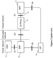
- Figure 1 illustrates the basic elements of GBA, which is a technology that enables authentication of a user.
- the User Equipment (UE) 10 is connected to the Bootstrapping Server Function (BSF) 20 through the Ub interface.
- the UE is also connected to the Network Application Function (NAF) through the Ua interface.
- the NAF 30 is connected to the BSF 20 through the Zn interface 50.
- the BSF 20 is connected to the Home Subscriber Server (HSS) 40 through the Zh interface.
- HSS Home Subscriber Server
- NAF Network Application Function
- BSF Bootstrapping Server Function
- the NAF is pulled out of the secure zone and brought into an enterprise network, for example, thus exposing the Zn interface to an untrusted network.
- IoT Internet of Things
- Patent application EP 1 811 744 A1 discloses a method for authenticating applied to a system including a first service entity requesting a service, a second service entity providing the service and an entity authentication centre, EAC.
- the method includes respectively performing a mutual authentication between the first service entity and the EAC and between the second service entity and the EAC according to the negotiated authentication mode. If the first service entity requests the second service entity to provide the service, the EAC provides authentication inquiring for the first service entity and the second service entity according to the negotiated authentication mode, and generates a shared derived key according to the negotiated authentication mode. The first service entity and the second service entity authenticate each other according to the shared derived key and the negotiated authentication mode.
- Patent application WO 2010/095988 A1 discloses a method of authenticating access to a service which comprises: a) receiving at a mobile terminal, over a bi-directional near-field communication channel between the mobile terminal and a browser, at least part of the identifier of a service; b) comparing, at the mobile terminal, at least part of the identifier received at the mobile terminal with a set of identifiers stored in the mobile device; and c) authenticating access to the service on the basis of whether at least part of the identifier received at the mobile terminal matches an identifier in the set.
- embodiments can be partially or completely embodied in the form of computer-readable carrier or carrier wave containing an appropriate set of computer instructions that would cause processing circuit to carry out the techniques described herein.
- the functions/actions may occur out of the order noted in the sequence of actions.
- some blocks, functions or actions may be optional and may or may not be executed.
- GBA General Bootstrapping Architecture
- NAF Network Application Function
- BSF Bootstrapping Server Function
- TLS Transport Layer Security
- Zn interface which is also called the Zn reference point.
- This TLS connection on the Zn interface can currently be accomplished only with the use of asymmetric encryption through the installation and use of certificates, i.e. private and public keys in the Application Function, e.g. the NAF, and in the Authentication Function, e.g. the BSF, respectively.
- a key pair is used.
- a public key is made public and available to other entities.
- a second, private key is kept secret. Any message that is encrypted by using a public key can only be decrypted by applying the same algorithm with the corresponding private key. Conversely, a message that is encrypted by using the private key can only be decrypted by using the corresponding public key.
- Asymmetric encryption has several disadvantages, especially in the context of the Internet of Things (IoT). First, it is slower than symmetric encryption (which will be described further below). Asymmetric encryption requires more processing power to both encrypt and decrypt the content of the message.
- Symmetric encryption is therefore a more flexible and expandable solution for establishing Transport Layer Security (TLS).
- Symmetric encryption is based on a shared secret, i.e. a secret key, which can be a number, a word, or just a string of random letters that is shared and applied on both ends to encrypt and decrypt messages.
- Embodiments described herein provide a solution for provisioning network nodes with a shared secret in a secure manner and for establishing a secure communication link on an interface between two network nodes using the shared secret.
- a method is defined for an Application Function, e.g. a NAF, located in an unsecure zone, to perform a bootstrapping procedure with an Authentication Function, e.g. a BSF.
- This method is proposed as a way to secure a new interface, called Znb, between the NAF and BSF.
- the NAF and BSF have a pre-shared key (PSK) which can be used to perform a TLS-PSK cipher, thus creating a secure channel, without the need of public/private certificates.
- PSK pre-shared key
- TLS-PSK is based on time-limited session keys from the GBA bootstrapping method and is more secured than TLS-PKI (which is based on certificates).
- the Application function e.g. the NAF
- SIM Subscriber Identity Module
- the GBA session key can then be used by the NAF to create a TLS-PSK tunnel with the Authentication Function, e.g. the BSF.
- FIG. 3 illustrates a system 100 comprising a Device 70, which can be a User Equipment (UE), a Machine-to-Machine (M2M) device, any type of connected computing device or any type of sensor device that needs to transmit and/or receive data.
- the system 100 comprises a secure zone 110, also called militarized zone, in which the Authentication Function 20 and the HSS 40 are located.
- the Authentication Function 20 and the HSS 40 can typically communicate securely in the secure zone.
- the Authentication Function 20 and the HSS 40 could, either or both, be located outside the secure zone 110, e.g. in the cloud.
- these nodes 20, 40 could run in a data center providing a pool of configurable computer resources.
- the system 100 also comprises an unsecure zone 90, in which the Application Function 30 and the Application Server 80 are located, and in which they can communicate with each other. Theses nodes are typically, but not necessarily, owned by the same entity.
- the system 100 includes the new Znb interface 55, which will be details further below.
- Figure 4 illustrates messages exchanged between the Application Function 30, located in an unsecure zone, the Authentication Function 20 and the HSS 40. The messages exchanged between these nodes will be further described in relation to the methods of Figures 5 and 6 .
- Figure 5 illustrates a method 300 for securing an interface and for securing a process for establishing a secure communication link between an Application Function 30 located in an unsecure zone and an Authentication Function 20.
- the method 300 comprises step 310 in which the Application Function 30 sends an authentication request message 120 to the Authentication Function 20.
- the method 300 comprises step 320 in which the Application Function 30 receives a response to the authentication request 150 from the Authentication Function including an authentication challenge.
- the method 300 comprises step 330 in which the Application Function 30 sends a challenge response 160 to the Authentication Function 20.
- the method 300 comprises step 340 in which, upon receiving a response indicating success 190 from the Authentication Function 20, the Application Function 30 generates a session key 200 using secret authentication credentials and information included in the authentication challenge (not illustrated).
- the method 300 comprises step 350 in which the Application Function 30 handshakes with the Authentication Function 20 and establishes the secure communication link 210 using the session key 200, thereby securing the interface 55 between the Application Function 30 and
- the Application Function may be a Network Application Function (NAF) 30 and the Authentication Function may be a Bootstrapping Server Functionality (BSF) 20 as defined in Generic Bootstrapping Architecture (GBA).
- NAF Network Application Function
- BAF Bootstrapping Server Functionality
- the interface 55 may be called a Znb interface or reference point between the NAF 30 and the BSF 20.
- Znb the actual "Znb" name could differ, as long as the method for securing the interface and for securing the process for establishing the secure communication link is the same.
- the authentication challenge may be an authentication vector generated by a Home Subscriber Server (HSS) 40 and the session keys may be Bootstrapping Key Session (Ksb) useable for a specific Application Function 30.
- HSS Home Subscriber Server
- Ksb Bootstrapping Key Session
- the information included in the authentication challenge can include a Message Authentication Code (MAC) and Random number (RAND), for example.
- MAC Message Authentication Code
- RAND Random number
- the secret authentication credentials that are stored in the Application Function 30 may comprise a physical Subscriber Identity Module (SIM), an embedded SIM or a software SIM.
- SIM Subscriber Identity Module
- a person skilled in the art would know that other variations of hardware or software authentication credentials, having security levels similar to that of a SIM card, could also be used interchangeably.
- the secure communication link may be a Transport Layer Security based on Pre-Shared Key ciphersuite (TLS-PSK) tunnel.
- TLS-PSK Pre-Shared Key ciphersuite
- Figure 6 illustrates a method 400 for securing an interface and for securing a process for establishing a secure communication link between an Application Function 30 located in an unsecure zone and an Authentication Function 20.
- the method 400 comprises step 410 in which the Authentication Function 20 receives an authentication request message 120 from the Application Function 30.
- the method 400 comprises step 420 in which the Authentication Function 20 sends a request for an authentication vector 130 to a Home Subscriber Server (HSS) 40 for an identifier provided in the authentication request message 120.
- HSS Home Subscriber Server
- the method 400 comprises step 430 in which the Authentication Function 20 receives a response 140 from the HSS 40 including the authentication vector.
- HSS Home Subscriber Server
- the method 400 comprises step 440 in which the Authentication Function 20 sends a response to the authentication request 150 to the Application Function 30 including an authentication challenge derived from the authentication vector.
- the method 400 comprises step 450 in which the Authentication Function 20 receives a challenge response 160 from the Application Function 30.
- the method 400 comprises step 460 in which upon validating the challenge response 170, the Authentication Function 20 generates a session key 180 using information included in the authentication vector.
- the method 400 comprises step 470 in which the Authentication Function 20 sends a response indicating success 190 to the Application Function 30.
- the method 400 comprises step 480 in which the Authentication Function 20 handshakes with the Application Function 30 and establishes the secure communication link 210 using the session key 180, thereby securing the interface between the Application Function 30 and the Authentication Function 20.
- Figure 7 illustrates an Application Function 30 node located in an unsecure zone for securing an interface and a process for establishing a secure communication link towards an Authentication Function 20, as described previously.
- the Application Function node 30 comprises a processor or processing circuit 500 and a memory 510, 520, the memory 510 is a transitory memory and the memory 520 is a non-transitory memory, the memory 510, 520 contains instructions executable by the processing circuit 500 whereby the Application Function 30 node is operative to execute a method 300 as described previously in relation to figure 5 .
- the Application Function 30 node further comprises at least one communications interface 530 to be able to communicate with a network or with other nodes as would be apparent to a person skilled in the art.
- Figure 8 illustrates an Authentication Function node 20 for securing an interface and a process for establishing a secure communication link towards an Application Function 30 located in an unsecure zone, as described previously.
- the Authentication function 20 node comprises a processor or processing circuit 500 and a memory 510, 520, the memory 510 is a transitory memory and the memory 520 is a non-transitory memory, the memory 510, 520 containing instructions executable by the processing circuit 500 whereby the Authentication Function 20 node is operative to execute a method 400 as described previously in relation to figure 6 .
- the Authentication Function node 20 further comprises at least one communications interface 530 to be able to communicate with a network or with other nodes as would be apparent to a person skilled in the art.
- FIG. 9 illustrates an Application Function node 30 located in an unsecure zone for securing an interface and a process for establishing a secure communication link towards an Authentication Function 20.
- the Application Function node 30 comprises a sending module 630 for sending an authentication request message 120 to the Authentication Function 20.
- the Application Function node 30 comprises a receiving module 630 for receiving a response to the authentication request 150 from the Authentication Function 20 including an authentication challenge.
- the sending and the receiving modules 630 could alternatively be separate modules.
- the sending module 630 is further for sending a challenge response 160 to the Authentication Function 20.
- the receiving module 630 is further for receiving a response indicating success 190 from the Authentication Function 20.
- the Application Function node 30 comprises a processing module 600 for generating a session key using secret authentication credentials and information included in the authentication challenge, upon receiving the response indicating success 190.
- the Application Function node 30 comprises a communication module 640 for handshaking with the Authentication Function 20 and establishing the secure communication link 210 using the session key, thereby securing the interface between the Application Function node 30 and the Authentication Function 20.
- the Application Function node 30 also comprises at least one memory module 610, 620, the memory module 610 is a transitory memory and the memory 620 is a non-transitory memory, the memory module 610, 620 containing instructions executable by the processing module.
- the Application Function node 30 is operative to execute a method 300 as described previously in relation to figure 5 .
- FIG 10 illustrates an Authentication Function node 20 for securing an interface and a process for establishing a secure communication link towards an Application Function 30 located in an unsecure zone.
- the Authentication Function node 20 comprises a receiving module 630 for receiving an authentication request message 120 from the Application Function.
- the Authentication Function node 20 comprises a sending module 630 for sending a request for an authentication vector 130 to a Home Subscriber Server (HSS) 40 for an identifier provided in the authentication request message 120.
- HSS Home Subscriber Server
- the sending and the receiving modules 630 could alternatively be separate modules.
- the receiving module 630 is further for receiving a response 140 from the HSS including the authentication vector.
- the sending module 630 is further for sending a response 150 to the authentication request to the Application Function 30 including an authentication challenge derived from the authentication vector.
- the receiving module 630 is further for receiving a challenge response 160 from the Application Function 30.
- the Authentication Function node 20 comprises a processing module 600 for generating a session key 180 using information included in the authentication vector, upon validating 170 the challenge response.
- the sending module 630 is further for sending a response indicating success 190 to the Application Function 30.
- the Authentication Function node 20 comprises a communication module 640 for handshaking with the Application Function 30 and establishing the secure communication link 210 using the session key, thereby securing the interface between the Application Function 30 and the Authentication Function node 20.
- the Authentication Function node 20 also comprises at least one memory module 610, 620, the memory module 610 is a transitory memory and the memory 620 is a non-transitory memory, the memory module 610, 620 containing instructions executable by the processing module.
- the Authentication Function node 20 is operative to execute a method 400 as described previously in relation to figure 6 .
- these nodes 20, 30 comprise one or several general-purpose or special-purpose processors 500, 600 or other microcontrollers programmed with suitable software programming instructions and/or firmware to carry out some or all of the functionality of the nodes 20, 30 described herein.
- the nodes 20, 30 may comprise various digital hardware blocks (e.g., one or more Application Specific Integrated Circuits (ASICs), one or more off-the-shelf digital or analog hardware components, or a combination thereof) (not illustrated) configured to carry out some or all of the functionality of the controller nodes 20, 30 described herein.
- ASICs Application Specific Integrated Circuits
- a memory 510, 610 such as a random access memory (RAM), may be used by the processor, or processing circuit, 500, 600 to store data and programming instructions which, when executed by the processor 500, 600, implement all or part of the functionality described herein.
- the nodes 20, 30 may also include one or more storage media 520, 620 for storing data necessary and/or suitable for implementing the functionality described herein, as well as for storing the programming instructions which, when executed on the processor 500, 600, implement all or part of the functionality described herein.
- One embodiment of the present disclosure may be implemented as a computer program product that is stored on a computer-readable storage medium, the computer program product including programming instructions that are configured to cause the processor 500, 600 to carry out the steps described herein.
- a non-transitory computer media 520, 620 having stored thereon instructions for securing an interface and for securing a process for establishing a secure communication link between an Application Function 30 and an Authentication Function 20.
- the instructions comprise steps of a method 300 as previously described in relation to figure 5 .
- non-transitory computer media 520, 620 having stored thereon instructions for securing an interface and for securing a process for establishing a secure communication link between an Application Function 30 and an Authentication Function 20.
- the instructions comprise steps of a method 400 as previously described in relation to figure 6 .
- an Application Function instance 720 located in an unsecure zone in a cloud computing environment 700 which provides processing circuit 760 and memory 790 for running the Application Function instance 720.
- the memory 790 contains instructions 795 executable by said processing circuit 760 whereby the Application Function instance 720 is operative to execute the method 300 as previously described in relation to figure 5 .
- the cloud computing environment 700 comprises a general-purpose network device including hardware 730 comprising a set of one or more processor(s) or processing circuit 760, which can be commercial off-the-shelf (COTS) processors, dedicated Application Specific Integrated Circuits (ASICs), or any other type of processing circuit including digital or analog hardware components or special purpose processors, and network interface controller(s) 770 (NICs), also known as network interface cards, which include physical Network Interface 780.
- the general-purpose network device also includes non-transitory machine readable storage media 790-2 having stored therein software 795 and/or instructions executable by the processor 760.
- the processor(s) 760 execute the software 795 to instantiate a hypervisor 750, sometimes referred to as a virtual machine monitor (VMM), and one or more virtual machines 740 that are run by the hypervisor 750.
- a virtual machine 740 is a software implementation of a physical machine that runs programs as if they were executing on a physical, non-virtualized machine; and applications generally do not know they are running on a virtual machine as opposed to running on a "bare metal" host electronic device, though some systems provide para-virtualization which allows an operating system or application to be aware of the presence of virtualization for optimization purposes.
- Each of the virtual machines 740, and that part of the hardware 730 that executes that virtual machine be it hardware dedicated to that virtual machine and/or time slices of hardware temporally shared by that virtual machine with others of the virtual machine(s) 740, forms a separate virtual network element(s) (VNE).
- VNE virtual network element
- the hypervisor 750 may present a virtual operating platform that appears like networking hardware to virtual machine 740, and the virtual machine 740 may be used to implement functionality such as control communication and configuration module(s) and forwarding table(s), this virtualization of the hardware is sometimes referred to as network function virtualization (NFV).
- NFV network function virtualization
- CPE customer premise equipment
- Different embodiments of the Application Function 30 and Authentication Function 20 instances may be implemented on one or more of the virtual machine(s) 740, and the implementations may be made differently.
- an Authentication Function instance 720 in a cloud computing environment 700 which provides processing circuit 760 and memory 790 for running the Authentication Function instance 720.
- the memory 790 contains instructions 795 executable by the processing circuit 760 whereby the Authentication Function instance 720 is operative to execute the method 400 as previously described in relation to figure 6 .
- a method 900 comprising the step 920 of initiating, by a user 810, an instantiation of an Application Function located in an unsecure zone in a cloud computing environment 800 which provides processing circuit and memory for running the Application Function, the Application function being operative to execute the method 300 as previously described in relation to figure 5 .
- a method 950 comprising the step 960 of initiating, by a user 810, an instantiation of an Authentication Function in a cloud computing environment 800 which provides processing circuit and memory for running the Authentication Function, the Authentication function being operative to execute the method 400 as previously described in relation to figure 6 .
- Figure 15 illustrates an example embodiment comprising a device 70, which can be, but is not limited to, a standalone device such as a sensor, a smart meter, a connected car, a medical device, a user equipment, a watch, a headset, glasses, a home appliance, etc.
- the device 70 may also be a plurality of devices, such as, but not limited to, an electrical grid, a network of connected devices, such as sensors, cameras, microphones, computing devices, cars, trucks, bus, trains, planes, bicycles, vending machines, industrial machinery, public utilities, smart buildings, meters, fixtures (light, heat, cooling), advertisement displays, etc.
- the HSS 40 is provisioned with secret authentication credentials pertaining to each Application Function 30 located in an unsecure zone. The same authentication credentials are also provisioned in the Application Functions 30.
- This step can be done offline (e.g. by inserting a physical SIM) or online (by provisioning the Application Function 30 with a software SIM, for example, as explained previously). This step has to be done in a secure manner, as would be apparent to a person skilled in the art.
- an Application Function 30 When an Application Function 30 is ready to authenticate with the Authentication Function 20, it performs the self-bootstrapping method 300, based on a shared secret, as explained previously in relation to figure 5 .
- a key derivation procedure can be used by the Authentication Function 20 to generate the session keys 180, 200 for a specific Application Function 30.
- a secure TLS PSK communication tunnel 210 is then established between the Application function 30 and the Authentication function 20, using the session keys 180, 200.
- the device 70 and the Authentication Function 20 can mutually authenticate using the second generation (2G) Authentication and Key Agreement (AKA) protocol (as described in the standard document referred to in the background section), and agree on session keys 1030 that are afterwards applied between the device 70 and a specific Application Function 30.
- a TLS PSK communication tunnel 1040 can then also be established between the device 70 and the Application Function 30, using the session keys 1030.
- the device 70 and Application Function 30 can run some application-specific protocol where the authentication of messages are based on the session keys 1030 generated during the mutual authentication between device 70 and Application Function 30.
- the device 70, the Application Function 30 and the Application Server 80 can then communicate securely.
Landscapes
- Engineering & Computer Science (AREA)
- Computer Security & Cryptography (AREA)
- Computer Networks & Wireless Communication (AREA)
- Signal Processing (AREA)
- General Engineering & Computer Science (AREA)
- Computer Hardware Design (AREA)
- Software Systems (AREA)
- Theoretical Computer Science (AREA)
- Computing Systems (AREA)
- Physics & Mathematics (AREA)
- General Physics & Mathematics (AREA)
- Mobile Radio Communication Systems (AREA)
- Telephonic Communication Services (AREA)
Description
- The present disclosure relates to securing an interface and a process for establishing a secure communication link between network entities.
- General Bootstrapping Architecture (GBA) is standardized and described in document 3GPP TS 33.220 V12.3.0 (2014-06) entitled "3rd Generation Partnership Project; Technical Specification Group Services and System Aspects; Generic Authentication Architecture (GAA); Generic Bootstrapping Architecture (GBA)".
-
Figure 1 illustrates the basic elements of GBA, which is a technology that enables authentication of a user. - The User Equipment (UE) 10 is connected to the Bootstrapping Server Function (BSF) 20 through the Ub interface. The UE is also connected to the Network Application Function (NAF) through the Ua interface. The NAF 30 is connected to the
BSF 20 through theZn interface 50. Finally, theBSF 20 is connected to the Home Subscriber Server (HSS) 40 through the Zh interface. The above mentioned standard document explains in more details the bootstrapping (which is another name for an authentication procedure) architecture and requirements on each interface Ub, Ua, Zh and Zn (which are called reference points in the standard document). - Historically, the Network Application Function (NAF) and the Bootstrapping Server Function (BSF) were both located in a secure zone, also called militarized zone, of, for example, an operator's network and could communicate without major security issues over the Zn interface. The NAF and BSF were securing the Zn interface using asymmetric encryption through the installation and use of certificates, i.e. private and public keys in the NAF and the BSF, respectively.
- Nowadays, however, with the advent of the Internet of Things (IoT), the NAF is pulled out of the secure zone and brought into an enterprise network, for example, thus exposing the Zn interface to an untrusted network.
- The solution illustrated in
Figure 2 , has been proposed which use a Zn-Proxy 60 to communicate with theBSF 20 through an untrusted network. This solution, however, adds a node to the visited network and cannot be easily scaled. - Patent application
EP 1 811 744 A1 discloses a method for authenticating applied to a system including a first service entity requesting a service, a second service entity providing the service and an entity authentication centre, EAC. The method includes respectively performing a mutual authentication between the first service entity and the EAC and between the second service entity and the EAC according to the negotiated authentication mode. If the first service entity requests the second service entity to provide the service, the EAC provides authentication inquiring for the first service entity and the second service entity according to the negotiated authentication mode, and generates a shared derived key according to the negotiated authentication mode. The first service entity and the second service entity authenticate each other according to the shared derived key and the negotiated authentication mode. - Patent application
WO 2010/095988 A1 discloses a method of authenticating access to a service which comprises: a) receiving at a mobile terminal, over a bi-directional near-field communication channel between the mobile terminal and a browser, at least part of the identifier of a service; b) comparing, at the mobile terminal, at least part of the identifier received at the mobile terminal with a set of identifiers stored in the mobile device; and c) authenticating access to the service on the basis of whether at least part of the identifier received at the mobile terminal matches an identifier in the set. - Non-patent literature Ericsson: ""Comments on S3-142418: PC3 security using HTTPDigestAKAv2 and TLS-PSK", 3GPP draft, S3-142543, SA WG3, November 2014 discloses mechanisms to secure the PC3 interface between the UE and the ProSe Function with the TLS-PSK protocol.
- There is therefore a need for another type of solution.
- According to aspects of the present disclosure, methods, nodes and media are provided according to the independent claims. Preferred embodiments are recited in the dependent claims.
-
-
Figure 1 is a schematic illustration of General Bootstrapping Architecture (GBA) according to the prior art. -
Figure 2 is a schematic illustration of a modified GBA according to the prior art. -
Figure 3 is a schematic illustration of GBA according to an embodiment. -
Figure 4 is a diagram illustrating message exchanges according to an embodiment. -
Figure 5 is a flowchart of a method executable by an Application Function according to an embodiment. -
Figure 6 is a flowchart of a method executable by an Authentication Function according to an embodiment. -
Figures 7 and9 illustrate Application Function nodes according to some embodiments. -
Figures 8 and10 illustrate Authentication Function nodes according to some embodiments. -
Figures 11-12 are schematic illustrations of a cloud environment in which embodiments can be deployed. -
Figures 13 and 14 are flowcharts of methods according to some embodiments. -
Figure 15 is a schematic illustration of an example according to an embodiment. - Various features and embodiments will now be described with reference to the figures to fully convey the scope of the disclosure to those skilled in the art.
- Many aspects will be described in terms of sequences of actions or functions. It should be recognized that in some embodiments, some functions or actions could be performed by specialized circuits, by program instructions being executed by one or more processors, or by a combination of both.
- Further, some embodiments can be partially or completely embodied in the form of computer-readable carrier or carrier wave containing an appropriate set of computer instructions that would cause processing circuit to carry out the techniques described herein.
- In some alternate embodiments, the functions/actions may occur out of the order noted in the sequence of actions. Furthermore, in some illustrations, some blocks, functions or actions may be optional and may or may not be executed.
- In current General Bootstrapping Architecture (GBA), for cases where the Network Application Function (NAF) is not located in a secure zone, also called militarized zone, with the Bootstrapping Server Function (BSF), Transport Layer Security (TLS) is defined as a secure method of transport for the Zn interface, which is also called the Zn reference point. This TLS connection on the Zn interface can currently be accomplished only with the use of asymmetric encryption through the installation and use of certificates, i.e. private and public keys in the Application Function, e.g. the NAF, and in the Authentication Function, e.g. the BSF, respectively.
- In asymmetric encryption, a key pair is used. A public key is made public and available to other entities. A second, private key is kept secret. Any message that is encrypted by using a public key can only be decrypted by applying the same algorithm with the corresponding private key. Conversely, a message that is encrypted by using the private key can only be decrypted by using the corresponding public key.
- Asymmetric encryption has several disadvantages, especially in the context of the Internet of Things (IoT). First, it is slower than symmetric encryption (which will be described further below). Asymmetric encryption requires more processing power to both encrypt and decrypt the content of the message.
- Second, using asymmetric encryption is limiting in the sense that Public Key Infrastructure (PKI) systems and certificates have to be used. Using PKI and certificates requires that a Certificate Authority validate the certificates. In the case of IoT, where there will be millions and eventually billions of connected devices, the certificate solution will suffer from scaling problems when a large amount of communication links has to be secured using TLS.
- Symmetric encryption is therefore a more flexible and expandable solution for establishing Transport Layer Security (TLS). Symmetric encryption is based on a shared secret, i.e. a secret key, which can be a number, a word, or just a string of random letters that is shared and applied on both ends to encrypt and decrypt messages.
- Embodiments described herein provide a solution for provisioning network nodes with a shared secret in a secure manner and for establishing a secure communication link on an interface between two network nodes using the shared secret.
- In one embodiment, a method is defined for an Application Function, e.g. a NAF, located in an unsecure zone, to perform a bootstrapping procedure with an Authentication Function, e.g. a BSF. This method is proposed as a way to secure a new interface, called Znb, between the NAF and BSF. Once the bootstrapping is accomplished, the NAF and BSF have a pre-shared key (PSK) which can be used to perform a TLS-PSK cipher, thus creating a secure channel, without the need of public/private certificates. Further, TLS-PSK is based on time-limited session keys from the GBA bootstrapping method and is more secured than TLS-PKI (which is based on certificates).
- In order to overcome some of the described problems, in the embodiments described below, the Application function, e.g. the NAF, may be provisioned with a Subscriber Identity Module (SIM) or alternatively with software SIM credentials (which is the software equivalent to the physical SIM). These credentials can be used during the bootstrapping to generate a GBA session key. The GBA session key can then be used by the NAF to create a TLS-PSK tunnel with the Authentication Function, e.g. the BSF.
-
Figure 3 illustrates asystem 100 comprising aDevice 70, which can be a User Equipment (UE), a Machine-to-Machine (M2M) device, any type of connected computing device or any type of sensor device that needs to transmit and/or receive data. Thesystem 100 comprises asecure zone 110, also called militarized zone, in which theAuthentication Function 20 and theHSS 40 are located. TheAuthentication Function 20 and theHSS 40 can typically communicate securely in the secure zone. It should be noted, however, that in some embodiments, theAuthentication Function 20 and theHSS 40 could, either or both, be located outside thesecure zone 110, e.g. in the cloud. For example, thesenodes system 100 also comprises anunsecure zone 90, in which theApplication Function 30 and theApplication Server 80 are located, and in which they can communicate with each other. Theses nodes are typically, but not necessarily, owned by the same entity. Thesystem 100 includes thenew Znb interface 55, which will be details further below. -
Figure 4 illustrates messages exchanged between theApplication Function 30, located in an unsecure zone, theAuthentication Function 20 and theHSS 40. The messages exchanged between these nodes will be further described in relation to the methods ofFigures 5 and6 . -
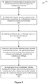
Figure 5 illustrates amethod 300 for securing an interface and for securing a process for establishing a secure communication link between anApplication Function 30 located in an unsecure zone and anAuthentication Function 20. Themethod 300 comprisesstep 310 in which theApplication Function 30 sends anauthentication request message 120 to theAuthentication Function 20. Themethod 300 comprisesstep 320 in which theApplication Function 30 receives a response to the authentication request 150 from the Authentication Function including an authentication challenge. Themethod 300 comprisesstep 330 in which theApplication Function 30 sends achallenge response 160 to theAuthentication Function 20. Themethod 300 comprisesstep 340 in which, upon receiving aresponse indicating success 190 from theAuthentication Function 20, theApplication Function 30 generates asession key 200 using secret authentication credentials and information included in the authentication challenge (not illustrated). Themethod 300 comprisesstep 350 in which theApplication Function 30 handshakes with theAuthentication Function 20 and establishes thesecure communication link 210 using thesession key 200, thereby securing theinterface 55 between theApplication Function 30 and theAuthentication Function 20. - As explained above, the Application Function may be a Network Application Function (NAF) 30 and the Authentication Function may be a Bootstrapping Server Functionality (BSF) 20 as defined in Generic Bootstrapping Architecture (GBA).
- The
interface 55 may be called a Znb interface or reference point between theNAF 30 and theBSF 20. However the actual "Znb" name could differ, as long as the method for securing the interface and for securing the process for establishing the secure communication link is the same. - In the
method 300, the authentication challenge may be an authentication vector generated by a Home Subscriber Server (HSS) 40 and the session keys may be Bootstrapping Key Session (Ksb) useable for aspecific Application Function 30. This means that the Ksb can be used for securing a link between theAuthentication Function 20 and only oneApplication Function 30. The information included in the authentication challenge can include a Message Authentication Code (MAC) and Random number (RAND), for example. - The secret authentication credentials that are stored in the
Application Function 30 may comprise a physical Subscriber Identity Module (SIM), an embedded SIM or a software SIM. A person skilled in the art would know that other variations of hardware or software authentication credentials, having security levels similar to that of a SIM card, could also be used interchangeably. - In the
method 300, the secure communication link may be a Transport Layer Security based on Pre-Shared Key ciphersuite (TLS-PSK) tunnel. -
Figure 6 illustrates amethod 400 for securing an interface and for securing a process for establishing a secure communication link between anApplication Function 30 located in an unsecure zone and anAuthentication Function 20. Themethod 400 comprisesstep 410 in which theAuthentication Function 20 receives anauthentication request message 120 from theApplication Function 30. Themethod 400 comprisesstep 420 in which theAuthentication Function 20 sends a request for anauthentication vector 130 to a Home Subscriber Server (HSS) 40 for an identifier provided in theauthentication request message 120. Themethod 400 comprisesstep 430 in which theAuthentication Function 20 receives aresponse 140 from theHSS 40 including the authentication vector. Themethod 400 comprisesstep 440 in which theAuthentication Function 20 sends a response to the authentication request 150 to theApplication Function 30 including an authentication challenge derived from the authentication vector. Themethod 400 comprisesstep 450 in which theAuthentication Function 20 receives achallenge response 160 from theApplication Function 30. Themethod 400 comprisesstep 460 in which upon validating thechallenge response 170, theAuthentication Function 20 generates asession key 180 using information included in the authentication vector. Themethod 400 comprisesstep 470 in which theAuthentication Function 20 sends aresponse indicating success 190 to theApplication Function 30. Themethod 400 comprisesstep 480 in which theAuthentication Function 20 handshakes with theApplication Function 30 and establishes thesecure communication link 210 using thesession key 180, thereby securing the interface between theApplication Function 30 and theAuthentication Function 20. -
Figure 7 illustrates anApplication Function 30 node located in an unsecure zone for securing an interface and a process for establishing a secure communication link towards anAuthentication Function 20, as described previously. TheApplication Function node 30 comprises a processor orprocessing circuit 500 and amemory memory 510 is a transitory memory and thememory 520 is a non-transitory memory, thememory processing circuit 500 whereby theApplication Function 30 node is operative to execute amethod 300 as described previously in relation tofigure 5 . TheApplication Function 30 node further comprises at least onecommunications interface 530 to be able to communicate with a network or with other nodes as would be apparent to a person skilled in the art. -
Figure 8 illustrates anAuthentication Function node 20 for securing an interface and a process for establishing a secure communication link towards anApplication Function 30 located in an unsecure zone, as described previously. TheAuthentication function 20 node comprises a processor orprocessing circuit 500 and amemory memory 510 is a transitory memory and thememory 520 is a non-transitory memory, thememory processing circuit 500 whereby theAuthentication Function 20 node is operative to execute amethod 400 as described previously in relation tofigure 6 . TheAuthentication Function node 20 further comprises at least onecommunications interface 530 to be able to communicate with a network or with other nodes as would be apparent to a person skilled in the art. -
Figure 9 illustrates anApplication Function node 30 located in an unsecure zone for securing an interface and a process for establishing a secure communication link towards anAuthentication Function 20. TheApplication Function node 30 comprises a sendingmodule 630 for sending anauthentication request message 120 to theAuthentication Function 20. TheApplication Function node 30 comprises a receivingmodule 630 for receiving a response to the authentication request 150 from theAuthentication Function 20 including an authentication challenge. The sending and the receivingmodules 630 could alternatively be separate modules. The sendingmodule 630 is further for sending achallenge response 160 to theAuthentication Function 20. The receivingmodule 630 is further for receiving aresponse indicating success 190 from theAuthentication Function 20. TheApplication Function node 30 comprises aprocessing module 600 for generating a session key using secret authentication credentials and information included in the authentication challenge, upon receiving theresponse indicating success 190. TheApplication Function node 30 comprises a communication module 640 for handshaking with theAuthentication Function 20 and establishing thesecure communication link 210 using the session key, thereby securing the interface between theApplication Function node 30 and theAuthentication Function 20. TheApplication Function node 30 also comprises at least onememory module memory module 610 is a transitory memory and thememory 620 is a non-transitory memory, thememory module Application Function node 30 is operative to execute amethod 300 as described previously in relation tofigure 5 . -
Figure 10 illustrates anAuthentication Function node 20 for securing an interface and a process for establishing a secure communication link towards anApplication Function 30 located in an unsecure zone. TheAuthentication Function node 20 comprises a receivingmodule 630 for receiving anauthentication request message 120 from the Application Function. TheAuthentication Function node 20 comprises a sendingmodule 630 for sending a request for anauthentication vector 130 to a Home Subscriber Server (HSS) 40 for an identifier provided in theauthentication request message 120. The sending and the receivingmodules 630 could alternatively be separate modules. The receivingmodule 630 is further for receiving aresponse 140 from the HSS including the authentication vector. The sendingmodule 630 is further for sending a response 150 to the authentication request to theApplication Function 30 including an authentication challenge derived from the authentication vector. The receivingmodule 630 is further for receiving achallenge response 160 from theApplication Function 30. TheAuthentication Function node 20 comprises aprocessing module 600 for generating asession key 180 using information included in the authentication vector, upon validating 170 the challenge response. The sendingmodule 630 is further for sending aresponse indicating success 190 to theApplication Function 30. TheAuthentication Function node 20 comprises a communication module 640 for handshaking with theApplication Function 30 and establishing thesecure communication link 210 using the session key, thereby securing the interface between theApplication Function 30 and theAuthentication Function node 20. TheAuthentication Function node 20 also comprises at least onememory module memory module 610 is a transitory memory and thememory 620 is a non-transitory memory, thememory module Authentication Function node 20 is operative to execute amethod 400 as described previously in relation tofigure 6 . - Although all of the details of the
Application Function node 30 andAuthentication Function node 20 offigures 7 to 10 are not illustrated, thesenodes purpose processors nodes nodes controller nodes memory processor nodes more storage media processor processor - Referring back to
figures 7 and9 , there are provided anon-transitory computer media Application Function 30 and anAuthentication Function 20. The instructions comprise steps of amethod 300 as previously described in relation tofigure 5 . - Referring back to
figures 8 and10 , there are providednon-transitory computer media Application Function 30 and anAuthentication Function 20. The instructions comprise steps of amethod 400 as previously described in relation tofigure 6 . - Referring to
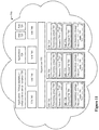
figure 11 , there is provided anApplication Function instance 720, located in an unsecure zone in acloud computing environment 700 which providesprocessing circuit 760 and memory 790 for running theApplication Function instance 720. The memory 790 containsinstructions 795 executable by saidprocessing circuit 760 whereby theApplication Function instance 720 is operative to execute themethod 300 as previously described in relation tofigure 5 . - The
cloud computing environment 700, comprises a general-purpose networkdevice including hardware 730 comprising a set of one or more processor(s) orprocessing circuit 760, which can be commercial off-the-shelf (COTS) processors, dedicated Application Specific Integrated Circuits (ASICs), or any other type of processing circuit including digital or analog hardware components or special purpose processors, and network interface controller(s) 770 (NICs), also known as network interface cards, which includephysical Network Interface 780. The general-purpose network device also includes non-transitory machine readable storage media 790-2 having stored thereinsoftware 795 and/or instructions executable by theprocessor 760. During operation, the processor(s) 760 execute thesoftware 795 to instantiate ahypervisor 750, sometimes referred to as a virtual machine monitor (VMM), and one or morevirtual machines 740 that are run by thehypervisor 750. Avirtual machine 740 is a software implementation of a physical machine that runs programs as if they were executing on a physical, non-virtualized machine; and applications generally do not know they are running on a virtual machine as opposed to running on a "bare metal" host electronic device, though some systems provide para-virtualization which allows an operating system or application to be aware of the presence of virtualization for optimization purposes. Each of thevirtual machines 740, and that part of thehardware 730 that executes that virtual machine, be it hardware dedicated to that virtual machine and/or time slices of hardware temporally shared by that virtual machine with others of the virtual machine(s) 740, forms a separate virtual network element(s) (VNE). - The
hypervisor 750 may present a virtual operating platform that appears like networking hardware tovirtual machine 740, and thevirtual machine 740 may be used to implement functionality such as control communication and configuration module(s) and forwarding table(s), this virtualization of the hardware is sometimes referred to as network function virtualization (NFV). Thus, NFV may be used to consolidate many network equipment types onto industry standard high volume server hardware, physical switches, and physical storage, which can be located in Data centers, and customer premise equipment (CPE). Different embodiments of theApplication Function 30 andAuthentication Function 20 instances may be implemented on one or more of the virtual machine(s) 740, and the implementations may be made differently. - Still referring to
figure 11 , there is provided anAuthentication Function instance 720, in acloud computing environment 700 which providesprocessing circuit 760 and memory 790 for running theAuthentication Function instance 720. The memory 790 containsinstructions 795 executable by theprocessing circuit 760 whereby theAuthentication Function instance 720 is operative to execute themethod 400 as previously described in relation tofigure 6 . - Referring to
figures 12 and13 there is provided amethod 900 comprising thestep 920 of initiating, by auser 810, an instantiation of an Application Function located in an unsecure zone in a cloud computing environment 800 which provides processing circuit and memory for running the Application Function, the Application function being operative to execute themethod 300 as previously described in relation tofigure 5 . - Still referring to
figure 12 and referring tofigure 14 , there is provided amethod 950 comprising thestep 960 of initiating, by auser 810, an instantiation of an Authentication Function in a cloud computing environment 800 which provides processing circuit and memory for running the Authentication Function, the Authentication function being operative to execute themethod 400 as previously described in relation tofigure 6 . -
Figure 15 illustrates an example embodiment comprising adevice 70, which can be, but is not limited to, a standalone device such as a sensor, a smart meter, a connected car, a medical device, a user equipment, a watch, a headset, glasses, a home appliance, etc. Thedevice 70 may also be a plurality of devices, such as, but not limited to, an electrical grid, a network of connected devices, such as sensors, cameras, microphones, computing devices, cars, trucks, bus, trains, planes, bicycles, vending machines, industrial machinery, public utilities, smart buildings, meters, fixtures (light, heat, cooling), advertisement displays, etc. - The
HSS 40 is provisioned with secret authentication credentials pertaining to eachApplication Function 30 located in an unsecure zone. The same authentication credentials are also provisioned in the Application Functions 30. This step can be done offline (e.g. by inserting a physical SIM) or online (by provisioning theApplication Function 30 with a software SIM, for example, as explained previously). This step has to be done in a secure manner, as would be apparent to a person skilled in the art. - When an
Application Function 30 is ready to authenticate with theAuthentication Function 20, it performs the self-bootstrappingmethod 300, based on a shared secret, as explained previously in relation tofigure 5 . A key derivation procedure can be used by theAuthentication Function 20 to generate thesession keys specific Application Function 30. A secure TLSPSK communication tunnel 210 is then established between theApplication function 30 and theAuthentication function 20, using thesession keys - Then, the
device 70 and theAuthentication Function 20 can mutually authenticate using the second generation (2G) Authentication and Key Agreement (AKA) protocol (as described in the standard document referred to in the background section), and agree onsession keys 1030 that are afterwards applied between thedevice 70 and aspecific Application Function 30. A TLSPSK communication tunnel 1040 can then also be established between thedevice 70 and theApplication Function 30, using thesession keys 1030. - After the bootstrapping has been completed, the
device 70 andApplication Function 30 can run some application-specific protocol where the authentication of messages are based on thesession keys 1030 generated during the mutual authentication betweendevice 70 andApplication Function 30. Thedevice 70, theApplication Function 30 and theApplication Server 80 can then communicate securely. - Modifications and other embodiments will come to mind to one skilled in the art having the benefit of the teachings presented in the foregoing description and the associated drawings. Therefore, it is to be understood that modifications and other embodiments, such as specific forms other than those of the embodiments described above, are intended to be included within the scope of this disclosure. The described embodiments are merely illustrative and should not be considered restrictive in any way. The scope sought is given by the appended claims, rather than the preceding description, and all variations and equivalents that fall within the range of the claims are intended to be embraced therein. Although specific terms may be employed herein, they are used in a generic and descriptive sense only and not for purposes of limitations.
Claims (15)
- A method for securing an interface (55) and for securing a process for establishing a secure communication link between a first Application Function (30) located in an unsecure zone and a second Authentication Function (20), comprising:- the first Application Function (30) sending (310) an authentication request message to the second Authentication Function (20);- the first Application Function (30) receiving (320) a response to the authentication request from the second Authentication Function (20) including an authentication challenge;- the first Application Function (30) sending (330) a challenge response to the second Authentication Function (20);- upon receiving a response indicating success from the second Authentication Function (20), the first Application Function (30) generating (340) a session key using secret authentication credentials and information included in the authentication challenge; and- the first Application Function (30) handshaking (350) with the second Authentication Function (20) and establishing the secure communication link using the session key, thereby securing the interface (50) between the first Application Function (30) and the second Authentication Function (20),
wherein the first Application Function (30) is a Network Application Function, NAF, and the second Authentication Function (20) is a Bootstrapping Server Functionality, BSF, as defined in Generic Bootstrapping Architecture, GBA. - The method of claim 1, wherein the interface (55) is an interface between the NAF and the BSF, and/or
wherein the authentication challenge is an authentication vector generated by a Home Subscriber Server, HSS, (40). - The method of claim 1 or 2, wherein the session keys are Bootstrapping Key Session, Ksb, useable for a specific Application Function (30), and/or
wherein the secret authentication credentials comprise a physical Subscriber Identity Module, SIM, an embedded SIM or a software SIM. - The method of any one of claims 1-3, wherein the information included in the authentication challenge includes a Message Authentication Code, MAC, and Random number, RAND, and/or
wherein the secure communication link is a Transport Layer Security based on Pre-Shared Key ciphersuite, TLS-PSK, tunnel. - A method for securing an interface (55) and for securing a process for establishing a secure communication link between a first Application Function (30) located in an unsecure zone and a second Authentication Function (20), comprising:- the second Authentication Function (20) receiving (410) an authentication request message from the , first Application Function (30);- the second Authentication Function (20) sending (420) a request for an authentication vector to a Home Subscriber Server, HSS, (40) for an identifier provided in the authentication request message;- the second Authentication Function (20) receiving (430) a response from the HSS (40) including the authentication vector;- the second Authentication Function (20) sending (440) a response to the authentication request to the first Application Function (30) including an authentication challenge derived from the authentication vector;- the second Authentication Function (20) receiving (450) a challenge response from the first Application Function (30);- upon validating the challenge response, the second Authentication Function (20) generating (460) a session key using information included in the authentication vector;- the second Authentication Function (20) sending (470) a response indicating success to the first Application Function (30); and- the second Authentication Function (20) handshaking (480) with the first Application Function (30) and establishing the secure communication link using the session key, thereby securing the interface (55) between the first Application Function (30) and the second Authentication Function (20),
wherein the first Application Function (30) is a Network Application Function, NAF, and the second Authentication Function (20) is a Bootstrapping Server Functionality, BSF, as defined in Generic Bootstrapping Architecture, GBA. - The method of claim 5, wherein the interface (55) is an interface between the NAF and the BSF, and/or
wherein the session keys are Bootstrapping Key Session, Ksb, useable for a specific Application Function (30). - The method of any one of claims 5 or 6, wherein the information included in the authentication challenge includes a Message Authentication Code, MAC, and Random number, RAND, and/or
wherein the secure communication link is a Transport Layer Security based on Pre-Shared Key ciphersuite, TLS-PSK, tunnel. - An Application Function (30) node located in an unsecure zone for securing an interface (55) and a process for establishing a secure communication link towards a second Authentication Function (20), the Application Function (30) node comprising a processing circuit (500) and a memory (510), said memory (510) containing instructions executable by said processing circuit (500) whereby said Application Function (30) node is operative to:- send (310) an authentication request message to the second Authentication Function (20);- receive (320) a response to the authentication request from the second Authentication Function (20) including an authentication challenge;- send (330) a challenge response to the second Authentication Function (20);- upon receiving a response indicating success from the second Authentication Function (20), generate (340) a session key using secret authentication credentials and information included in the authentication challenge; and- handshake (350) with the second Authentication Function (20) and establish the secure communication link using the session key, thereby securing the interface (55) between the Application Function (30) and the Authentication Function (20),
wherein the Application Function (30) node is a Network Application Function, NAF, and the second Authentication Function (20) is a Bootstrapping Server Functionality, BSF, as defined in Generic Bootstrapping Architecture, GBA. - The Application Function (30) node of claim 8, wherein the interface (55) is an interface between the NAF and the BSF, and/or
wherein the authentication challenge is an authentication vector generated by a Home Subscriber Server, HSS, (40). - The Application Function (30) node of claim 8 or 9, wherein the session keys are Bootstrapping Key Session, Ksb, useable for a specific Application Function (30), and/or
wherein the secret authentication credentials comprise a physical Subscriber Identity Module, SIM, an embedded SIM or a software SIM. - The Application Function (30) node of any one of claims 8-10, wherein the information included in the authentication challenge includes a Message Authentication Code, MAC, and Random number, RAND, and/or
wherein the secure communication link is a Transport Layer Security based on Pre-Shared Key ciphersuite, TLS-PSK, tunnel. - An Authentication Function (20) node for securing an interface (55) and a process for establishing a secure communication link towards an a first Application Function (30) located in an unsecure zone, the Authentication Function (20) node comprising a processing circuit (500) and a memory (510), said memory (510) containing instructions executable by said processing circuit (500) whereby said Authentication Function (20) node is operative to:- receive (410) an authentication request message from the first Application Function (30);- send (420) a request for an authentication vector to a Home Subscriber Server, HSS, (40) for an identifier provided in the authentication request message;- receive (430) a response from the HSS (40) including the authentication vector;- send (440) a response to the authentication request to the first Application Function (30) including an authentication challenge derived from the authentication vector;- receive (450) a challenge response from the first Application Function (30);- upon validating the challenge response, generate (460) a session key using information included in the authentication vector;- send (470) a response indicating success to the first Application Function (30); and- handshake (480) with the first Application Function (30) and establish the secure communication link using the session key, thereby securing the interface (55) between the first Application Function (30) and the Authentication Function (20),
wherein the first Application Function (30) is a Network Application Function, NAF, and the Authentication Function (20) node is a Bootstrapping Server Functionality, BSF, as defined in Generic Bootstrapping Architecture, GBA. - The Authentication Function (20) node of claim 12, wherein the interface (55) is an interface between the NAF and the BSF, and/or
wherein the session keys are Bootstrapping Key Session, Ksb, useable for a specific Application Function (30). - The Authentication Function (20) node of claim 12 or 13, wherein the information included in the authentication challenge includes a Message Authentication Code, MAC, and Random number, RAND, and/or
wherein the secure communication link is a Transport Layer Security based on Pre-Shared Key ciphersuite, TLS-PSK, tunnel. - A non-transitory computer media having stored thereon instructions for securing an interface and for securing a process for establishing a secure communication link between first Application Function (30) located in an unsecure zone and an a second Authentication Function (20), said instructions comprising instructions for executing the method of any one of claims 1-7.
Applications Claiming Priority (1)
| Application Number | Priority Date | Filing Date | Title |
|---|---|---|---|
| PCT/IB2016/050770 WO2017137809A1 (en) | 2016-02-12 | 2016-02-12 | Securing an interface and a process for establishing a secure communication link |
Publications (2)
| Publication Number | Publication Date |
|---|---|
| EP3414927A1 EP3414927A1 (en) | 2018-12-19 |
| EP3414927B1 true EP3414927B1 (en) | 2020-06-24 |
Family
ID=55409878
Family Applications (1)
| Application Number | Title | Priority Date | Filing Date |
|---|---|---|---|
| EP16706001.1A Active EP3414927B1 (en) | 2016-02-12 | 2016-02-12 | Securing an interface and a process for establishing a secure communication link |
Country Status (4)
| Country | Link |
|---|---|
| US (1) | US20190020643A1 (en) |
| EP (1) | EP3414927B1 (en) |
| CN (1) | CN108702615B (en) |
| WO (1) | WO2017137809A1 (en) |
Families Citing this family (1)
| Publication number | Priority date | Publication date | Assignee | Title |
|---|---|---|---|---|
| GB2540354A (en) * | 2015-07-13 | 2017-01-18 | Vodafone Ip Licensing Ltd | Generci bootstrapping architecture protocol |
Family Cites Families (20)
| Publication number | Priority date | Publication date | Assignee | Title |
|---|---|---|---|---|
| CN100466515C (en) * | 2003-11-11 | 2009-03-04 | 华为技术有限公司 | Method for establishing interaction between conversation business mark and network application entity |
| CN100512137C (en) * | 2004-04-22 | 2009-07-08 | 华为技术有限公司 | A method for deleting session transaction ID and related information |
| US8726023B2 (en) * | 2005-02-03 | 2014-05-13 | Nokia Corporation | Authentication using GAA functionality for unidirectional network connections |
| FI20050384A0 (en) * | 2005-04-14 | 2005-04-14 | Nokia Corp | Use of generic authentication architecture for distribution of Internet protocol keys in mobile terminals |
| DE102005026982A1 (en) * | 2005-06-10 | 2006-12-14 | Siemens Ag | Method for agreeing a security key between at least one first and a second communication subscriber for securing a communication connection |
| US20070101122A1 (en) * | 2005-09-23 | 2007-05-03 | Yile Guo | Method and apparatus for securely generating application session keys |
| US8122240B2 (en) * | 2005-10-13 | 2012-02-21 | Telefonaktiebolaget Lm Ericsson (Publ) | Method and apparatus for establishing a security association |
| KR101009330B1 (en) * | 2006-01-24 | 2011-01-18 | 후아웨이 테크놀러지 컴퍼니 리미티드 | Method, system and authentication centre for authenticating in end-to-end communications based on a mobile network |
| CN101052032B (en) * | 2006-04-04 | 2010-05-12 | 华为技术有限公司 | Business entity certifying method and device |
| CN101039311B (en) * | 2006-03-16 | 2010-05-12 | 华为技术有限公司 | Identification web page service network system and its authentication method |
| US8522025B2 (en) * | 2006-03-28 | 2013-08-27 | Nokia Corporation | Authenticating an application |
| ES2706540T3 (en) * | 2006-07-06 | 2019-03-29 | Nokia Technologies Oy | User equipment credentials system |
| KR101084938B1 (en) * | 2007-10-05 | 2011-11-18 | 인터디지탈 테크날러지 코포레이션 | Techniques for secure channelization between uicc and a terminal |
| WO2010095988A1 (en) * | 2009-02-18 | 2010-08-26 | Telefonaktiebolaget L M Ericsson (Publ) | User authentication |
| CN102065421B (en) * | 2009-11-11 | 2014-10-08 | 中国移动通信集团公司 | Method, device and system for updating key |
| US8509431B2 (en) * | 2010-09-20 | 2013-08-13 | Interdigital Patent Holdings, Inc. | Identity management on a wireless device |
| KR20140037276A (en) * | 2011-03-23 | 2014-03-26 | 인터디지탈 패튼 홀딩스, 인크 | Systems and methods for securing network communications |
| US8990554B2 (en) * | 2011-06-30 | 2015-03-24 | Verizon Patent And Licensing Inc. | Network optimization for secure connection establishment or secure messaging |
| IN2014CN03915A (en) * | 2011-10-31 | 2015-10-16 | Nokia Corp | |
| EP2912815B1 (en) * | 2012-10-29 | 2016-06-29 | Telefonaktiebolaget LM Ericsson (publ) | Method and apparatus for securing a connection in a communications network |
-
2016
- 2016-02-12 WO PCT/IB2016/050770 patent/WO2017137809A1/en active Application Filing
- 2016-02-12 US US16/070,080 patent/US20190020643A1/en not_active Abandoned
- 2016-02-12 EP EP16706001.1A patent/EP3414927B1/en active Active
- 2016-02-12 CN CN201680081522.6A patent/CN108702615B/en active Active
Non-Patent Citations (1)
| Title |
|---|
| None * |
Also Published As
| Publication number | Publication date |
|---|---|
| CN108702615B (en) | 2022-08-05 |
| EP3414927A1 (en) | 2018-12-19 |
| US20190020643A1 (en) | 2019-01-17 |
| CN108702615A (en) | 2018-10-23 |
| WO2017137809A1 (en) | 2017-08-17 |
Similar Documents
| Publication | Publication Date | Title |
|---|---|---|
| US11272365B2 (en) | Network authentication method, and related device and system | |
| US10986083B2 (en) | Hardware identification-based security authentication service for IoT devices | |
| US10129031B2 (en) | End-to-end service layer authentication | |
| US9654284B2 (en) | Group based bootstrapping in machine type communication | |
| KR102051492B1 (en) | Method and Apparatus for Providing Machine-to-Machine Service | |
| CN106788989B (en) | Method and equipment for establishing secure encrypted channel | |
| JP2018532325A (en) | User equipment UE access method, access device, and access system | |
| CN112311543B (en) | GBA key generation method, terminal and NAF network element | |
| US20180270653A1 (en) | Methods and apparatus for direct communication key establishment | |
| BR112021003460A2 (en) | device with no subscriber identity, device with subscriber identity, method for use on a device without subscriber identity, method for use on a device with subscriber identity, and computer program product | |
| US11316670B2 (en) | Secure communications using network access identity | |
| WO2020029735A1 (en) | Extensible authentication method and device based on generic bootstrapping architecture, and storage medium | |
| CN110999215A (en) | Secure device access token | |
| US11924634B2 (en) | Methods providing authentication using a request commit message and related user equipment and network nodes | |
| EP3414927B1 (en) | Securing an interface and a process for establishing a secure communication link | |
| US9602493B2 (en) | Implicit challenge authentication process | |
| KR20140030518A (en) | Mutual authentication method and system with network in machine type communication, key distribution method and system, and uicc and device pair authentication method and system in machine type communication | |
| US11343675B2 (en) | Communication device authentication for multiple communication devices | |
| TWI656771B (en) | Bluetooth communication method, device and device thereof | |
| WO2020041933A1 (en) | Methods and devices for a secure connection |
Legal Events
| Date | Code | Title | Description |
|---|---|---|---|
| STAA | Information on the status of an ep patent application or granted ep patent |
Free format text: STATUS: THE INTERNATIONAL PUBLICATION HAS BEEN MADE |
|
| PUAI | Public reference made under article 153(3) epc to a published international application that has entered the european phase |
Free format text: ORIGINAL CODE: 0009012 |
|
| STAA | Information on the status of an ep patent application or granted ep patent |
Free format text: STATUS: REQUEST FOR EXAMINATION WAS MADE |
|
| 17P | Request for examination filed |
Effective date: 20180905 |
|
| AK | Designated contracting states |
Kind code of ref document: A1 Designated state(s): AL AT BE BG CH CY CZ DE DK EE ES FI FR GB GR HR HU IE IS IT LI LT LU LV MC MK MT NL NO PL PT RO RS SE SI SK SM TR |
|
| AX | Request for extension of the european patent |
Extension state: BA ME |
|
| DAV | Request for validation of the european patent (deleted) | ||
| DAX | Request for extension of the european patent (deleted) | ||
| GRAP | Despatch of communication of intention to grant a patent |
Free format text: ORIGINAL CODE: EPIDOSNIGR1 |
|
| STAA | Information on the status of an ep patent application or granted ep patent |
Free format text: STATUS: GRANT OF PATENT IS INTENDED |
|
| INTG | Intention to grant announced |
Effective date: 20200302 |
|
| GRAS | Grant fee paid |
Free format text: ORIGINAL CODE: EPIDOSNIGR3 |
|
| GRAA | (expected) grant |
Free format text: ORIGINAL CODE: 0009210 |
|
| STAA | Information on the status of an ep patent application or granted ep patent |
Free format text: STATUS: THE PATENT HAS BEEN GRANTED |
|
| AK | Designated contracting states |
Kind code of ref document: B1 Designated state(s): AL AT BE BG CH CY CZ DE DK EE ES FI FR GB GR HR HU IE IS IT LI LT LU LV MC MK MT NL NO PL PT RO RS SE SI SK SM TR |
|
| REG | Reference to a national code |
Ref country code: GB Ref legal event code: FG4D |
|
| REG | Reference to a national code |
Ref country code: CH Ref legal event code: EP |
|
| REG | Reference to a national code |
Ref country code: AT Ref legal event code: REF Ref document number: 1285130 Country of ref document: AT Kind code of ref document: T Effective date: 20200715 |
|
| REG | Reference to a national code |
Ref country code: DE Ref legal event code: R096 Ref document number: 602016038643 Country of ref document: DE |
|
| REG | Reference to a national code |
Ref country code: IE Ref legal event code: FG4D |
|
| PG25 | Lapsed in a contracting state [announced via postgrant information from national office to epo] |
Ref country code: LT Free format text: LAPSE BECAUSE OF FAILURE TO SUBMIT A TRANSLATION OF THE DESCRIPTION OR TO PAY THE FEE WITHIN THE PRESCRIBED TIME-LIMIT Effective date: 20200624 Ref country code: FI Free format text: LAPSE BECAUSE OF FAILURE TO SUBMIT A TRANSLATION OF THE DESCRIPTION OR TO PAY THE FEE WITHIN THE PRESCRIBED TIME-LIMIT Effective date: 20200624 Ref country code: NO Free format text: LAPSE BECAUSE OF FAILURE TO SUBMIT A TRANSLATION OF THE DESCRIPTION OR TO PAY THE FEE WITHIN THE PRESCRIBED TIME-LIMIT Effective date: 20200924 Ref country code: GR Free format text: LAPSE BECAUSE OF FAILURE TO SUBMIT A TRANSLATION OF THE DESCRIPTION OR TO PAY THE FEE WITHIN THE PRESCRIBED TIME-LIMIT Effective date: 20200925 Ref country code: SE Free format text: LAPSE BECAUSE OF FAILURE TO SUBMIT A TRANSLATION OF THE DESCRIPTION OR TO PAY THE FEE WITHIN THE PRESCRIBED TIME-LIMIT Effective date: 20200624 |
|
| REG | Reference to a national code |
Ref country code: LT Ref legal event code: MG4D |
|
| PG25 | Lapsed in a contracting state [announced via postgrant information from national office to epo] |
Ref country code: BG Free format text: LAPSE BECAUSE OF FAILURE TO SUBMIT A TRANSLATION OF THE DESCRIPTION OR TO PAY THE FEE WITHIN THE PRESCRIBED TIME-LIMIT Effective date: 20200924 Ref country code: RS Free format text: LAPSE BECAUSE OF FAILURE TO SUBMIT A TRANSLATION OF THE DESCRIPTION OR TO PAY THE FEE WITHIN THE PRESCRIBED TIME-LIMIT Effective date: 20200624 Ref country code: HR Free format text: LAPSE BECAUSE OF FAILURE TO SUBMIT A TRANSLATION OF THE DESCRIPTION OR TO PAY THE FEE WITHIN THE PRESCRIBED TIME-LIMIT Effective date: 20200624 Ref country code: LV Free format text: LAPSE BECAUSE OF FAILURE TO SUBMIT A TRANSLATION OF THE DESCRIPTION OR TO PAY THE FEE WITHIN THE PRESCRIBED TIME-LIMIT Effective date: 20200624 |
|
| REG | Reference to a national code |
Ref country code: NL Ref legal event code: MP Effective date: 20200624 |
|
| REG | Reference to a national code |
Ref country code: AT Ref legal event code: MK05 Ref document number: 1285130 Country of ref document: AT Kind code of ref document: T Effective date: 20200624 |
|
| PG25 | Lapsed in a contracting state [announced via postgrant information from national office to epo] |
Ref country code: AL Free format text: LAPSE BECAUSE OF FAILURE TO SUBMIT A TRANSLATION OF THE DESCRIPTION OR TO PAY THE FEE WITHIN THE PRESCRIBED TIME-LIMIT Effective date: 20200624 Ref country code: NL Free format text: LAPSE BECAUSE OF FAILURE TO SUBMIT A TRANSLATION OF THE DESCRIPTION OR TO PAY THE FEE WITHIN THE PRESCRIBED TIME-LIMIT Effective date: 20200624 |
|
| PG25 | Lapsed in a contracting state [announced via postgrant information from national office to epo] |
Ref country code: CZ Free format text: LAPSE BECAUSE OF FAILURE TO SUBMIT A TRANSLATION OF THE DESCRIPTION OR TO PAY THE FEE WITHIN THE PRESCRIBED TIME-LIMIT Effective date: 20200624 Ref country code: ES Free format text: LAPSE BECAUSE OF FAILURE TO SUBMIT A TRANSLATION OF THE DESCRIPTION OR TO PAY THE FEE WITHIN THE PRESCRIBED TIME-LIMIT Effective date: 20200624 Ref country code: PT Free format text: LAPSE BECAUSE OF FAILURE TO SUBMIT A TRANSLATION OF THE DESCRIPTION OR TO PAY THE FEE WITHIN THE PRESCRIBED TIME-LIMIT Effective date: 20201026 Ref country code: AT Free format text: LAPSE BECAUSE OF FAILURE TO SUBMIT A TRANSLATION OF THE DESCRIPTION OR TO PAY THE FEE WITHIN THE PRESCRIBED TIME-LIMIT Effective date: 20200624 Ref country code: EE Free format text: LAPSE BECAUSE OF FAILURE TO SUBMIT A TRANSLATION OF THE DESCRIPTION OR TO PAY THE FEE WITHIN THE PRESCRIBED TIME-LIMIT Effective date: 20200624 Ref country code: SM Free format text: LAPSE BECAUSE OF FAILURE TO SUBMIT A TRANSLATION OF THE DESCRIPTION OR TO PAY THE FEE WITHIN THE PRESCRIBED TIME-LIMIT Effective date: 20200624 Ref country code: RO Free format text: LAPSE BECAUSE OF FAILURE TO SUBMIT A TRANSLATION OF THE DESCRIPTION OR TO PAY THE FEE WITHIN THE PRESCRIBED TIME-LIMIT Effective date: 20200624 Ref country code: IT Free format text: LAPSE BECAUSE OF FAILURE TO SUBMIT A TRANSLATION OF THE DESCRIPTION OR TO PAY THE FEE WITHIN THE PRESCRIBED TIME-LIMIT Effective date: 20200624 |
|
| PG25 | Lapsed in a contracting state [announced via postgrant information from national office to epo] |
Ref country code: IS Free format text: LAPSE BECAUSE OF FAILURE TO SUBMIT A TRANSLATION OF THE DESCRIPTION OR TO PAY THE FEE WITHIN THE PRESCRIBED TIME-LIMIT Effective date: 20201024 Ref country code: PL Free format text: LAPSE BECAUSE OF FAILURE TO SUBMIT A TRANSLATION OF THE DESCRIPTION OR TO PAY THE FEE WITHIN THE PRESCRIBED TIME-LIMIT Effective date: 20200624 Ref country code: SK Free format text: LAPSE BECAUSE OF FAILURE TO SUBMIT A TRANSLATION OF THE DESCRIPTION OR TO PAY THE FEE WITHIN THE PRESCRIBED TIME-LIMIT Effective date: 20200624 |
|
| REG | Reference to a national code |
Ref country code: DE Ref legal event code: R097 Ref document number: 602016038643 Country of ref document: DE |
|
| PG25 | Lapsed in a contracting state [announced via postgrant information from national office to epo] |
Ref country code: DK Free format text: LAPSE BECAUSE OF FAILURE TO SUBMIT A TRANSLATION OF THE DESCRIPTION OR TO PAY THE FEE WITHIN THE PRESCRIBED TIME-LIMIT Effective date: 20200624 |
|
| PLBE | No opposition filed within time limit |
Free format text: ORIGINAL CODE: 0009261 |
|
| STAA | Information on the status of an ep patent application or granted ep patent |
Free format text: STATUS: NO OPPOSITION FILED WITHIN TIME LIMIT |
|
| 26N | No opposition filed |
Effective date: 20210325 |
|
| PG25 | Lapsed in a contracting state [announced via postgrant information from national office to epo] |
Ref country code: SI Free format text: LAPSE BECAUSE OF FAILURE TO SUBMIT A TRANSLATION OF THE DESCRIPTION OR TO PAY THE FEE WITHIN THE PRESCRIBED TIME-LIMIT Effective date: 20200624 |
|
| PG25 | Lapsed in a contracting state [announced via postgrant information from national office to epo] |
Ref country code: MC Free format text: LAPSE BECAUSE OF FAILURE TO SUBMIT A TRANSLATION OF THE DESCRIPTION OR TO PAY THE FEE WITHIN THE PRESCRIBED TIME-LIMIT Effective date: 20200624 |
|
| REG | Reference to a national code |
Ref country code: BE Ref legal event code: MM Effective date: 20210228 |
|
| PG25 | Lapsed in a contracting state [announced via postgrant information from national office to epo] |
Ref country code: LI Free format text: LAPSE BECAUSE OF NON-PAYMENT OF DUE FEES Effective date: 20210228 Ref country code: LU Free format text: LAPSE BECAUSE OF NON-PAYMENT OF DUE FEES Effective date: 20210212 Ref country code: CH Free format text: LAPSE BECAUSE OF NON-PAYMENT OF DUE FEES Effective date: 20210228 |
|
| PG25 | Lapsed in a contracting state [announced via postgrant information from national office to epo] |
Ref country code: IE Free format text: LAPSE BECAUSE OF NON-PAYMENT OF DUE FEES Effective date: 20210212 Ref country code: FR Free format text: LAPSE BECAUSE OF NON-PAYMENT OF DUE FEES Effective date: 20210228 |
|
| PG25 | Lapsed in a contracting state [announced via postgrant information from national office to epo] |
Ref country code: BE Free format text: LAPSE BECAUSE OF NON-PAYMENT OF DUE FEES Effective date: 20210228 |
|
| PG25 | Lapsed in a contracting state [announced via postgrant information from national office to epo] |
Ref country code: CY Free format text: LAPSE BECAUSE OF FAILURE TO SUBMIT A TRANSLATION OF THE DESCRIPTION OR TO PAY THE FEE WITHIN THE PRESCRIBED TIME-LIMIT Effective date: 20200624 |
|
| PG25 | Lapsed in a contracting state [announced via postgrant information from national office to epo] |
Ref country code: HU Free format text: LAPSE BECAUSE OF FAILURE TO SUBMIT A TRANSLATION OF THE DESCRIPTION OR TO PAY THE FEE WITHIN THE PRESCRIBED TIME-LIMIT; INVALID AB INITIO Effective date: 20160212 |
|
| PG25 | Lapsed in a contracting state [announced via postgrant information from national office to epo] |
Ref country code: MK Free format text: LAPSE BECAUSE OF FAILURE TO SUBMIT A TRANSLATION OF THE DESCRIPTION OR TO PAY THE FEE WITHIN THE PRESCRIBED TIME-LIMIT Effective date: 20200624 |
|
| PGFP | Annual fee paid to national office [announced via postgrant information from national office to epo] |
Ref country code: DE Payment date: 20240228 Year of fee payment: 9 Ref country code: GB Payment date: 20240227 Year of fee payment: 9 |