EP3409362B1 - Method for manufacturing a test element for detecting an analyte in a body fluid, test element and method of use - Google Patents
Method for manufacturing a test element for detecting an analyte in a body fluid, test element and method of use Download PDFInfo
- Publication number
- EP3409362B1 EP3409362B1 EP17173730.7A EP17173730A EP3409362B1 EP 3409362 B1 EP3409362 B1 EP 3409362B1 EP 17173730 A EP17173730 A EP 17173730A EP 3409362 B1 EP3409362 B1 EP 3409362B1
- Authority
- EP
- European Patent Office
- Prior art keywords
- test
- test chemical
- substrate
- hydrophilic
- specifically
- Prior art date
- Legal status (The legal status is an assumption and is not a legal conclusion. Google has not performed a legal analysis and makes no representation as to the accuracy of the status listed.)
- Active
Links
- 238000012360 testing method Methods 0.000 title claims description 371
- 238000000034 method Methods 0.000 title claims description 153
- 210000001124 body fluid Anatomy 0.000 title claims description 94
- 239000010839 body fluid Substances 0.000 title claims description 94
- 239000012491 analyte Substances 0.000 title claims description 68
- 238000004519 manufacturing process Methods 0.000 title claims description 48
- 239000000126 substance Substances 0.000 claims description 192
- 239000000758 substrate Substances 0.000 claims description 151
- 239000000463 material Substances 0.000 claims description 139
- 238000001514 detection method Methods 0.000 claims description 27
- 239000004094 surface-active agent Substances 0.000 claims description 24
- 238000005259 measurement Methods 0.000 claims description 23
- -1 polysiloxane Polymers 0.000 claims description 21
- 229920000642 polymer Polymers 0.000 claims description 13
- 238000006243 chemical reaction Methods 0.000 claims description 12
- 230000003287 optical effect Effects 0.000 claims description 11
- 239000004372 Polyvinyl alcohol Substances 0.000 claims description 10
- 229920002451 polyvinyl alcohol Polymers 0.000 claims description 10
- 229920000515 polycarbonate Polymers 0.000 claims description 8
- 239000004417 polycarbonate Substances 0.000 claims description 8
- 229920000728 polyester Polymers 0.000 claims description 8
- 229920002635 polyurethane Polymers 0.000 claims description 8
- 239000004814 polyurethane Substances 0.000 claims description 8
- 238000005192 partition Methods 0.000 claims description 7
- 239000002202 Polyethylene glycol Substances 0.000 claims description 6
- 229920001223 polyethylene glycol Polymers 0.000 claims description 6
- 239000004952 Polyamide Substances 0.000 claims description 5
- 239000004642 Polyimide Substances 0.000 claims description 5
- 239000004721 Polyphenylene oxide Substances 0.000 claims description 5
- 229920002678 cellulose Polymers 0.000 claims description 5
- 239000001913 cellulose Substances 0.000 claims description 5
- 229920000058 polyacrylate Polymers 0.000 claims description 5
- 229920002647 polyamide Polymers 0.000 claims description 5
- 229920000570 polyether Polymers 0.000 claims description 5
- 229920001721 polyimide Polymers 0.000 claims description 5
- 229920000098 polyolefin Polymers 0.000 claims description 5
- 229920001296 polysiloxane Polymers 0.000 claims description 5
- 229920001290 polyvinyl ester Polymers 0.000 claims description 5
- 229920001289 polyvinyl ether Polymers 0.000 claims description 5
- 239000003945 anionic surfactant Substances 0.000 claims description 3
- 239000010410 layer Substances 0.000 description 121
- 239000011888 foil Substances 0.000 description 86
- 238000005507 spraying Methods 0.000 description 43
- 239000000853 adhesive Substances 0.000 description 38
- 230000001070 adhesive effect Effects 0.000 description 38
- 230000002209 hydrophobic effect Effects 0.000 description 25
- 230000032258 transport Effects 0.000 description 23
- 238000000576 coating method Methods 0.000 description 22
- 239000002904 solvent Substances 0.000 description 21
- 239000011248 coating agent Substances 0.000 description 20
- 239000000243 solution Substances 0.000 description 20
- 239000000725 suspension Substances 0.000 description 18
- XLYOFNOQVPJJNP-UHFFFAOYSA-N water Substances O XLYOFNOQVPJJNP-UHFFFAOYSA-N 0.000 description 14
- 210000004369 blood Anatomy 0.000 description 13
- 239000008280 blood Substances 0.000 description 13
- 229910052729 chemical element Inorganic materials 0.000 description 12
- 239000002609 medium Substances 0.000 description 12
- 239000013067 intermediate product Substances 0.000 description 11
- 230000008569 process Effects 0.000 description 11
- 239000002245 particle Substances 0.000 description 10
- 239000007921 spray Substances 0.000 description 10
- 230000008859 change Effects 0.000 description 9
- 238000002474 experimental method Methods 0.000 description 9
- 239000012530 fluid Substances 0.000 description 8
- 239000007788 liquid Substances 0.000 description 8
- 239000007787 solid Substances 0.000 description 8
- WQZGKKKJIJFFOK-GASJEMHNSA-N Glucose Natural products OC[C@H]1OC(O)[C@H](O)[C@@H](O)[C@@H]1O WQZGKKKJIJFFOK-GASJEMHNSA-N 0.000 description 7
- 229940088598 enzyme Drugs 0.000 description 7
- 239000008103 glucose Substances 0.000 description 7
- 229920000139 polyethylene terephthalate Polymers 0.000 description 7
- 239000005020 polyethylene terephthalate Substances 0.000 description 7
- 239000011148 porous material Substances 0.000 description 7
- 210000001519 tissue Anatomy 0.000 description 7
- 108090000790 Enzymes Proteins 0.000 description 6
- 102000004190 Enzymes Human genes 0.000 description 6
- 238000001035 drying Methods 0.000 description 5
- 239000007789 gas Substances 0.000 description 5
- 238000009736 wetting Methods 0.000 description 5
- HVYWMOMLDIMFJA-DPAQBDIFSA-N cholesterol Chemical compound C1C=C2C[C@@H](O)CC[C@]2(C)[C@@H]2[C@@H]1[C@@H]1CC[C@H]([C@H](C)CCCC(C)C)[C@@]1(C)CC2 HVYWMOMLDIMFJA-DPAQBDIFSA-N 0.000 description 4
- 239000003814 drug Substances 0.000 description 4
- 238000000840 electrochemical analysis Methods 0.000 description 4
- 230000014509 gene expression Effects 0.000 description 4
- 150000002433 hydrophilic molecules Chemical class 0.000 description 4
- 230000005660 hydrophilic surface Effects 0.000 description 4
- 238000010030 laminating Methods 0.000 description 4
- YLGXILFCIXHCMC-JHGZEJCSSA-N methyl cellulose Chemical compound COC1C(OC)C(OC)C(COC)O[C@H]1O[C@H]1C(OC)C(OC)C(OC)OC1COC YLGXILFCIXHCMC-JHGZEJCSSA-N 0.000 description 4
- 239000011241 protective layer Substances 0.000 description 4
- ZQTYRTSKQFQYPQ-UHFFFAOYSA-N trisiloxane Chemical compound [SiH3]O[SiH2]O[SiH3] ZQTYRTSKQFQYPQ-UHFFFAOYSA-N 0.000 description 4
- HNSDLXPSAYFUHK-UHFFFAOYSA-N 1,4-bis(2-ethylhexyl) sulfosuccinate Chemical compound CCCCC(CC)COC(=O)CC(S(O)(=O)=O)C(=O)OCC(CC)CCCC HNSDLXPSAYFUHK-UHFFFAOYSA-N 0.000 description 3
- 239000004743 Polypropylene Substances 0.000 description 3
- 239000004793 Polystyrene Substances 0.000 description 3
- 210000004027 cell Anatomy 0.000 description 3
- 238000005345 coagulation Methods 0.000 description 3
- 230000015271 coagulation Effects 0.000 description 3
- 150000001875 compounds Chemical class 0.000 description 3
- 238000005520 cutting process Methods 0.000 description 3
- 230000001419 dependent effect Effects 0.000 description 3
- 238000000151 deposition Methods 0.000 description 3
- 238000003618 dip coating Methods 0.000 description 3
- 229940079593 drug Drugs 0.000 description 3
- 238000000835 electrochemical detection Methods 0.000 description 3
- 210000003722 extracellular fluid Anatomy 0.000 description 3
- 238000005534 hematocrit Methods 0.000 description 3
- 230000005661 hydrophobic surface Effects 0.000 description 3
- 239000002346 layers by function Substances 0.000 description 3
- 239000002207 metabolite Substances 0.000 description 3
- 239000000203 mixture Substances 0.000 description 3
- 229920003229 poly(methyl methacrylate) Polymers 0.000 description 3
- 239000004926 polymethyl methacrylate Substances 0.000 description 3
- 229920001155 polypropylene Polymers 0.000 description 3
- 229920002223 polystyrene Polymers 0.000 description 3
- 239000004800 polyvinyl chloride Substances 0.000 description 3
- 229920000915 polyvinyl chloride Polymers 0.000 description 3
- 210000003296 saliva Anatomy 0.000 description 3
- 238000000926 separation method Methods 0.000 description 3
- 239000011877 solvent mixture Substances 0.000 description 3
- 210000002700 urine Anatomy 0.000 description 3
- JVTAAEKCZFNVCJ-UHFFFAOYSA-M Lactate Chemical compound CC(O)C([O-])=O JVTAAEKCZFNVCJ-UHFFFAOYSA-M 0.000 description 2
- WYURNTSHIVDZCO-UHFFFAOYSA-N Tetrahydrofuran Chemical compound C1CCOC1 WYURNTSHIVDZCO-UHFFFAOYSA-N 0.000 description 2
- 238000004458 analytical method Methods 0.000 description 2
- WQZGKKKJIJFFOK-VFUOTHLCSA-N beta-D-glucose Chemical compound OC[C@H]1O[C@@H](O)[C@H](O)[C@@H](O)[C@@H]1O WQZGKKKJIJFFOK-VFUOTHLCSA-N 0.000 description 2
- 239000003153 chemical reaction reagent Substances 0.000 description 2
- 235000012000 cholesterol Nutrition 0.000 description 2
- 238000013461 design Methods 0.000 description 2
- 239000002612 dispersion medium Substances 0.000 description 2
- 229940018602 docusate Drugs 0.000 description 2
- 239000000975 dye Substances 0.000 description 2
- 238000005516 engineering process Methods 0.000 description 2
- 230000007613 environmental effect Effects 0.000 description 2
- 125000001165 hydrophobic group Chemical group 0.000 description 2
- 150000002632 lipids Chemical class 0.000 description 2
- 238000012544 monitoring process Methods 0.000 description 2
- 230000000704 physical effect Effects 0.000 description 2
- 210000002381 plasma Anatomy 0.000 description 2
- 229920001692 polycarbonate urethane Polymers 0.000 description 2
- 108090000623 proteins and genes Proteins 0.000 description 2
- 102000004169 proteins and genes Human genes 0.000 description 2
- 210000002966 serum Anatomy 0.000 description 2
- 229920001169 thermoplastic Polymers 0.000 description 2
- 150000003626 triacylglycerols Chemical class 0.000 description 2
- 241000448280 Elates Species 0.000 description 1
- 108010050375 Glucose 1-Dehydrogenase Proteins 0.000 description 1
- 108010015776 Glucose oxidase Proteins 0.000 description 1
- 239000004366 Glucose oxidase Substances 0.000 description 1
- CBENFWSGALASAD-UHFFFAOYSA-N Ozone Chemical compound [O-][O+]=O CBENFWSGALASAD-UHFFFAOYSA-N 0.000 description 1
- 239000004902 Softening Agent Substances 0.000 description 1
- 108090000190 Thrombin Proteins 0.000 description 1
- 238000009825 accumulation Methods 0.000 description 1
- XECAHXYUAAWDEL-UHFFFAOYSA-N acrylonitrile butadiene styrene Chemical compound C=CC=C.C=CC#N.C=CC1=CC=CC=C1 XECAHXYUAAWDEL-UHFFFAOYSA-N 0.000 description 1
- 239000004676 acrylonitrile butadiene styrene Substances 0.000 description 1
- 229920000122 acrylonitrile butadiene styrene Polymers 0.000 description 1
- 230000003213 activating effect Effects 0.000 description 1
- 230000004913 activation Effects 0.000 description 1
- 230000009056 active transport Effects 0.000 description 1
- 238000004026 adhesive bonding Methods 0.000 description 1
- 229910010293 ceramic material Inorganic materials 0.000 description 1
- 238000007796 conventional method Methods 0.000 description 1
- 238000011161 development Methods 0.000 description 1
- 230000018109 developmental process Effects 0.000 description 1
- 206010012601 diabetes mellitus Diseases 0.000 description 1
- 238000009826 distribution Methods 0.000 description 1
- 229960000878 docusate sodium Drugs 0.000 description 1
- 230000000694 effects Effects 0.000 description 1
- 230000002708 enhancing effect Effects 0.000 description 1
- 238000006911 enzymatic reaction Methods 0.000 description 1
- 210000003743 erythrocyte Anatomy 0.000 description 1
- 230000002349 favourable effect Effects 0.000 description 1
- 238000009472 formulation Methods 0.000 description 1
- 229940116332 glucose oxidase Drugs 0.000 description 1
- 235000019420 glucose oxidase Nutrition 0.000 description 1
- 150000004676 glycans Chemical class 0.000 description 1
- 239000008241 heterogeneous mixture Substances 0.000 description 1
- 239000008240 homogeneous mixture Substances 0.000 description 1
- 239000012456 homogeneous solution Substances 0.000 description 1
- 229910052739 hydrogen Inorganic materials 0.000 description 1
- 239000001257 hydrogen Substances 0.000 description 1
- 230000006872 improvement Effects 0.000 description 1
- 238000001746 injection moulding Methods 0.000 description 1
- 238000003780 insertion Methods 0.000 description 1
- 230000037431 insertion Effects 0.000 description 1
- 230000003993 interaction Effects 0.000 description 1
- 239000012528 membrane Substances 0.000 description 1
- 230000004060 metabolic process Effects 0.000 description 1
- 239000000693 micelle Substances 0.000 description 1
- 238000002156 mixing Methods 0.000 description 1
- 230000007935 neutral effect Effects 0.000 description 1
- ORQBXQOJMQIAOY-UHFFFAOYSA-N nobelium Chemical compound [No] ORQBXQOJMQIAOY-UHFFFAOYSA-N 0.000 description 1
- 239000012454 non-polar solvent Substances 0.000 description 1
- 150000002894 organic compounds Chemical class 0.000 description 1
- TWNQGVIAIRXVLR-UHFFFAOYSA-N oxo(oxoalumanyloxy)alumane Chemical compound O=[Al]O[Al]=O TWNQGVIAIRXVLR-UHFFFAOYSA-N 0.000 description 1
- 229920002959 polymer blend Polymers 0.000 description 1
- 229920001282 polysaccharide Polymers 0.000 description 1
- 239000005017 polysaccharide Substances 0.000 description 1
- 238000007639 printing Methods 0.000 description 1
- 238000012545 processing Methods 0.000 description 1
- 150000003839 salts Chemical class 0.000 description 1
- 238000004062 sedimentation Methods 0.000 description 1
- 238000011895 specific detection Methods 0.000 description 1
- 239000013589 supplement Substances 0.000 description 1
- YLQBMQCUIZJEEH-UHFFFAOYSA-N tetrahydrofuran Natural products C=1C=COC=1 YLQBMQCUIZJEEH-UHFFFAOYSA-N 0.000 description 1
- 229960004072 thrombin Drugs 0.000 description 1
- 238000012546 transfer Methods 0.000 description 1
- 238000003466 welding Methods 0.000 description 1
Images


Classifications
-
- B—PERFORMING OPERATIONS; TRANSPORTING
- B01—PHYSICAL OR CHEMICAL PROCESSES OR APPARATUS IN GENERAL
- B01L—CHEMICAL OR PHYSICAL LABORATORY APPARATUS FOR GENERAL USE
- B01L3/00—Containers or dishes for laboratory use, e.g. laboratory glassware; Droppers
- B01L3/50—Containers for the purpose of retaining a material to be analysed, e.g. test tubes
- B01L3/502—Containers for the purpose of retaining a material to be analysed, e.g. test tubes with fluid transport, e.g. in multi-compartment structures
- B01L3/5027—Containers for the purpose of retaining a material to be analysed, e.g. test tubes with fluid transport, e.g. in multi-compartment structures by integrated microfluidic structures, i.e. dimensions of channels and chambers are such that surface tension forces are important, e.g. lab-on-a-chip
- B01L3/502707—Containers for the purpose of retaining a material to be analysed, e.g. test tubes with fluid transport, e.g. in multi-compartment structures by integrated microfluidic structures, i.e. dimensions of channels and chambers are such that surface tension forces are important, e.g. lab-on-a-chip characterised by the manufacture of the container or its components
-
- B—PERFORMING OPERATIONS; TRANSPORTING
- B01—PHYSICAL OR CHEMICAL PROCESSES OR APPARATUS IN GENERAL
- B01L—CHEMICAL OR PHYSICAL LABORATORY APPARATUS FOR GENERAL USE
- B01L3/00—Containers or dishes for laboratory use, e.g. laboratory glassware; Droppers
- B01L3/50—Containers for the purpose of retaining a material to be analysed, e.g. test tubes
- B01L3/502—Containers for the purpose of retaining a material to be analysed, e.g. test tubes with fluid transport, e.g. in multi-compartment structures
- B01L3/5027—Containers for the purpose of retaining a material to be analysed, e.g. test tubes with fluid transport, e.g. in multi-compartment structures by integrated microfluidic structures, i.e. dimensions of channels and chambers are such that surface tension forces are important, e.g. lab-on-a-chip
- B01L3/502715—Containers for the purpose of retaining a material to be analysed, e.g. test tubes with fluid transport, e.g. in multi-compartment structures by integrated microfluidic structures, i.e. dimensions of channels and chambers are such that surface tension forces are important, e.g. lab-on-a-chip characterised by interfacing components, e.g. fluidic, electrical, optical or mechanical interfaces
-
- B—PERFORMING OPERATIONS; TRANSPORTING
- B01—PHYSICAL OR CHEMICAL PROCESSES OR APPARATUS IN GENERAL
- B01L—CHEMICAL OR PHYSICAL LABORATORY APPARATUS FOR GENERAL USE
- B01L2200/00—Solutions for specific problems relating to chemical or physical laboratory apparatus
- B01L2200/12—Specific details about manufacturing devices
-
- B—PERFORMING OPERATIONS; TRANSPORTING
- B01—PHYSICAL OR CHEMICAL PROCESSES OR APPARATUS IN GENERAL
- B01L—CHEMICAL OR PHYSICAL LABORATORY APPARATUS FOR GENERAL USE
- B01L2300/00—Additional constructional details
- B01L2300/04—Closures and closing means
- B01L2300/046—Function or devices integrated in the closure
- B01L2300/047—Additional chamber, reservoir
-
- B—PERFORMING OPERATIONS; TRANSPORTING
- B01—PHYSICAL OR CHEMICAL PROCESSES OR APPARATUS IN GENERAL
- B01L—CHEMICAL OR PHYSICAL LABORATORY APPARATUS FOR GENERAL USE
- B01L2300/00—Additional constructional details
- B01L2300/06—Auxiliary integrated devices, integrated components
- B01L2300/0627—Sensor or part of a sensor is integrated
- B01L2300/0663—Whole sensors
-
- B—PERFORMING OPERATIONS; TRANSPORTING
- B01—PHYSICAL OR CHEMICAL PROCESSES OR APPARATUS IN GENERAL
- B01L—CHEMICAL OR PHYSICAL LABORATORY APPARATUS FOR GENERAL USE
- B01L2300/00—Additional constructional details
- B01L2300/08—Geometry, shape and general structure
- B01L2300/0809—Geometry, shape and general structure rectangular shaped
- B01L2300/0825—Test strips
-
- B—PERFORMING OPERATIONS; TRANSPORTING
- B01—PHYSICAL OR CHEMICAL PROCESSES OR APPARATUS IN GENERAL
- B01L—CHEMICAL OR PHYSICAL LABORATORY APPARATUS FOR GENERAL USE
- B01L2300/00—Additional constructional details
- B01L2300/08—Geometry, shape and general structure
- B01L2300/0887—Laminated structure
-
- B—PERFORMING OPERATIONS; TRANSPORTING
- B01—PHYSICAL OR CHEMICAL PROCESSES OR APPARATUS IN GENERAL
- B01L—CHEMICAL OR PHYSICAL LABORATORY APPARATUS FOR GENERAL USE
- B01L2300/00—Additional constructional details
- B01L2300/12—Specific details about materials
-
- B—PERFORMING OPERATIONS; TRANSPORTING
- B01—PHYSICAL OR CHEMICAL PROCESSES OR APPARATUS IN GENERAL
- B01L—CHEMICAL OR PHYSICAL LABORATORY APPARATUS FOR GENERAL USE
- B01L2300/00—Additional constructional details
- B01L2300/16—Surface properties and coatings
- B01L2300/161—Control and use of surface tension forces, e.g. hydrophobic, hydrophilic
-
- B—PERFORMING OPERATIONS; TRANSPORTING
- B01—PHYSICAL OR CHEMICAL PROCESSES OR APPARATUS IN GENERAL
- B01L—CHEMICAL OR PHYSICAL LABORATORY APPARATUS FOR GENERAL USE
- B01L2400/00—Moving or stopping fluids
- B01L2400/04—Moving fluids with specific forces or mechanical means
- B01L2400/0403—Moving fluids with specific forces or mechanical means specific forces
- B01L2400/0406—Moving fluids with specific forces or mechanical means specific forces capillary forces
-
- B—PERFORMING OPERATIONS; TRANSPORTING
- B01—PHYSICAL OR CHEMICAL PROCESSES OR APPARATUS IN GENERAL
- B01L—CHEMICAL OR PHYSICAL LABORATORY APPARATUS FOR GENERAL USE
- B01L2400/00—Moving or stopping fluids
- B01L2400/08—Regulating or influencing the flow resistance
- B01L2400/084—Passive control of flow resistance
- B01L2400/088—Passive control of flow resistance by specific surface properties
Definitions
- the methods and devices according to the present invention may be used for detecting at least one analyte present in one or both of a body tissue or a body fluid, in particular the method and devices may be applied in the field of detecting one or more analytes such as glucose, lactate, triglycerides, cholesterol or other analytes, preferably metabolites, in body fluids such as blood, preferably whole blood, plasma, serum, urine, saliva, interstitial fluid or other body fluids, both in the field of professional diagnostics and in the field of home monitoring.
- analytes such as glucose, lactate, triglycerides, cholesterol or other analytes, preferably metabolites
- body fluids such as blood, preferably whole blood, plasma, serum, urine, saliva, interstitial fluid or other body fluids, both in the field of professional diagnostics and in the field of home monitoring.
- body fluids such as blood, preferably whole blood, plasma, serum, urine, saliva, interstitial fluid or other body fluids, both in the field of
- the method and devices may be used for detecting at least one analyte present in one or both of a body tissue or a body fluid, in particular one or more analytes such as glucose, lactate, triglycerides, cholesterol or other analytes, preferably metabolites, in body fluids such as blood, preferably whole blood, plasma, serum, urine, saliva, interstitial fluid or other body fluids.
- Further devices are known for measuring activating times, e.g. a thrombin activation time measurement for coagulation monitoring.
- test devices are known in the art, such as for measuring blood glucose concentration during work, leisure or other activities away from home.
- test devices are commercially available.
- a large number of test devices and test systems are known which are based on the use of test elements in the form of test strips.
- Applications are known, in which a multiplicity of test strips is provided by a magazine, wherein a test strip from the magazine automatically may be provided to the testing device.
- Other applications are known in which single test strips are used, which are inserted into the testing device manually by a user.
- test strip typically, the end of the test strip is adapted to be inserted into the testing device and for detecting the analyte, wherein the opposing end of the test strip serves as a handle enabling the user to push the test strip into the testing device or to remove the test strip from the testing device.
- sample application site such as a capillary opening in capillary test elements or a sprite net in optical test strips having a top dosing system. Test strips of this type are commercially available, e.g. under the trade name Accu-Chek Active ® .
- test elements may be used in professional diagnostics, such as in hospital applications.
- test elements are used, such as test strips, which comprise one or more test fields having one or more test chemistries.
- the test chemistries are adapted to change one or more detectable properties in the presence of the analyte to be detected.
- electrochemically detectable properties of the test chemistry and/or optically detectable properties of the test chemistry may be changed due to the influence of the presence of the analyte.
- test chemistries which may be used within the present invention, reference may be made to J. Hönes et al.: Diabetes Technology and Therapeutics, Vol. 10, Supplement 1, 2008, S-10 to S-26 .
- other types of test chemistries may be used within the present invention.
- the detection of the at least one analyte can be performed by using an electrochemical test element.
- an electrochemical test element Commonly used are disposable electrochemical capillary sensor test elements.
- Such test elements typically comprise at least one working electrode for detecting the analyte as well as at least one counter electrode to support a current flow through a measuring cell of the test element.
- the test element may comprise at least one reference electrode.
- a reference electrode may be designed individually and/or may be combined with the counter electrode.
- other types of measurement setups are possible, in order to derive an analyte concentration from a comparison of electrode potentials.
- test elements may be comprise several layers, the layers being manufactured by a combination of conventional methods such as dip coating or laminating individual foils.
- the transcutaneous analyte sensor system can include an applicator, a mounting unit, an electronics unit, a base adapted for mounting on a skin of a host, and one or more contacts configured to provide electrical contact between the sensor and the electronics unit.
- EP 2681329 A1 a method for producing a test element for studying a body fluid sample is described.
- the detection layer is covered with a polymeric spread layer and applied to a support.
- the spread layer is produced by being sprayed onto the detection layer.
- the invention further elates to such a test element having a spread layer that has a thickness of at most 20 ⁇ m.
- EP 1 035 919 B1 a device for the capillary transport of a liquid between two opposite lying, essentially planar layers is described. Both layers are arranged at a distance from and parallel to one another in such a way that a capillary active gap is created between both layers.
- the invention is characterized in such a way that at least one of the layers comprises at least two discrete adjacent parts, and that the capillary active transport of the liquid can flow beyond the common boundary of the parts which are situated in a layer.
- the coagulation parameter comprises a carrier; at least two electrodes, which are applied on the carrier; at least one test reagent; and a surfactant-containing coating.
- US 2016/082434 discloses a method of manufacturing a test element for detecting at least one analyte in a body fluid comprising providing at least one substrate having at least one elongate receptacle; placing one test chemical on the substrate; placing one cover element on the substrate. It also anticipates the method of using said test element for detecting one analyte in a body fluid.
- It is therefore an objective of the present invention to provide a method for manufacturing a test element for detecting at least one analyte in a body fluid, a test element for detecting at least one analyte in a body fluid, a method for detecting at least one analyte in a body fluid, a system for detecting at least one analyte in a body fluid and a method for manufacturing a test element for detecting at least one analyte in a body fluid which at least partially avoid the shortcomings of known devices and methods of this kind and which at least partially address the above-mentioned challenges.
- methods shall be disclosed which allow for easy manufacturing of test elements.
- a method and a device for a method for manufacturing a test element for detecting at least one analyte in a body fluid a test element for detecting at least one analyte in a body fluid, a method for detecting at least one analyte in a body fluid, a system for detecting at least one analyte in a body fluid and a method for manufacturing a test element for detecting at least one analyte in a body fluid with the features of the independent claims.
- Preferred embodiments, which might be realized in an isolated fashion or in any arbitrary combination, are listed in the dependent claims.
- the terms “have”, “comprise” or “include” or any arbitrary grammatical variations thereof are used in a non-exclusive way. Thus, these terms may both refer to a situation in which, besides the feature introduced by these terms, no further features are present in the entity described in this context and to a situation in which one or more further features are present.
- the expressions “A has B”, “A comprises B” and “A includes B” may both refer to a situation in which, besides B, no other element is present in A (i.e. a situation in which A solely and exclusively consists of B) and to a situation in which, besides B, one or more further elements are present in entity A, such as element C, elements C and D or even further elements.
- the terms "at least one”, “one or more” or similar expressions indicating that a feature or element may be present once or more than once typically will be used only once when introducing the respective feature or element.
- the expressions “at least one” or “one or more” will not be repeated, non-withstanding the fact that the respective feature or element may be present once or more than once.
- a method for manufacturing a test element for detecting at least one analyte in a body fluid comprises the method steps as given in the independent claim and as listed as follows.
- the method steps may be performed in the given order. However, other orders of the method steps are feasible. Further, one or more of the method steps may be performed in parallel and/or on a timely overlapping fashion. Further, one or more of the method steps may be performed repeatedly. Further, additional method steps may be present which are not listed.
- the method for manufacturing a test element for detecting at least one analyte in a body fluid comprises the following steps:
- the term “manufacturing” may refer to an arbitrary process of producing or assembling an arbitrary device, specifically in a mechanical way.
- the term manufacturing may refer to a value added production of a device for use.
- the manufacturing process may comprise a number of different manufacturing steps which may be performed in a given order. However, one or more of the manufacturing steps may be performed in parallel and/or on a timely overlapping fashion. Further, one or more of the manufacturing steps may be performed repeatedly.
- the manufacturing process may begin with a creation of materials from which a device is made. These materials may then be modified through the manufacturing process to become the desired device. Further, exemplarily, the device may be assembled by combining several separate components. However, other embodiments may be feasible.
- test element may refer an arbitrary device which is capable of detecting the analyte in a sample or of determining at least one parameter of the sample.
- the test element may therefore have at least one receptacle which is configured to receive the sample.
- the test element may have at least one test field wherein the detection of the analyte in the sample or the determination of the at least one parameter occurs.
- the test field may comprise at least one test chemistry which will further be described below in more detail.
- the test element may be an arbitrary monolithic device or an arbitrary one-piece device. Specifically, the test element may be a strip-shaped test element.
- strip-shaped refers to an element having an elongated shape and a thickness, wherein an extension of the element in a lateral dimension exceeds the thickness of the element, such as by at least a factor of 2, preferably by at least a factor of 5, more preferably by at least a factor of 10 and most preferably by at least a factor of 20 or even at least a factor of 30.
- the test element may also be referred to as test strip.
- analyte may generally refer to an arbitrary element, component or compound which may be present in the sample and the presence and/or the concentration of which may be of interest for the user, the patient or medical staff such as a medical doctor.
- the analyte may be or may comprise an arbitrary chemical substance or chemical compound which may take part in the metabolism of the user or the patient, such as at least one metabolite.
- the detection of the at least one analyte specifically may be an analyte-specific detection.
- body fluid may refer to a fluid which typically is present in a body or body tissue of the user or the patient and/or which may be produced by the body of the user or the patient.
- body tissue interstitial tissue may be named.
- the body fluid may be selected from the group consisting of blood and interstitial fluid.
- one or more other types of body fluids may be used, such as saliva, tear fluid, urine or other body fluids.
- the sensor may be configured for detecting at least one analyte in a body tissue.
- the term "detecting” may generally refer to a process of determining a presence and/or a quantity and/or a concentration of the at least one analyte.
- the detection may be or may comprise a qualitative detection, simply determining a presence of the at least one analyte or a absence of the at least one analyte, and/or may be or may comprise a quantitative detection, which determines the quantity and/or the concentration of the at least one analyte.
- at least one signal may be produced which characterizes an outcome of the detection, such as at least one measurement signal.
- the at least one signal specifically may be or may comprise at least one electronic signal such as at least one voltage and/or at least one current.
- the at least one signal may be or may comprise at least one analogue signal and/or may be or may comprise at least one digital signal. Therefore, the detection may be conducted via at least one sensor.
- the term "sensor” may generally refer to an arbitrary element which is adapted to perform a process of detection and/or which is adapted to be used in the process of detection. Thus, the sensor specifically may be adapted to determine the concentration of the analyte and/or a presence of the analyte.
- the sensor may be part of a measurement device or analytical device as will further be described below in more detail.
- the at least one substrate is provided.
- the term "substrate” may refer to an arbitrary element which is suitable to carry one or more other elements disposed thereon or therein.
- the substrate may be a flat substrate, such as a substrate having a lateral extension exceeding its thickness by at least a factor of 2, at least a factor of 5, at least a factor of 10, or even at least a factor of 20 or more.
- the substrate specifically may have an elongated shape, such as a strip-shape and/or a bar-shape.
- the substrate may be at least partially manufactured of at least one hydrophobic material.
- hydrophobic may refer to a physical property of a molecule, specifically of a molecule of an arbitrary solid element or of an arbitrary fluidic medium, of being repelled form a mass of water.
- hydrophobic molecules tend to be nonpolar and, thus, prefer other neutral molecules and nonpolar solvents. Because water molecules are polar, the hydrophobic molecules do not dissolve well among them.
- the hydrophobic molecules in water often cluster together, forming micelles. Water on hydrophobic surfaces may exhibit a high contact angle. In contrast, hydrophilic molecules are generally attracted to water as will further be described below in more detail.
- the substrate may be manufactured of at least one polymer, specifically of at least one thermoplastic polymer.
- the substrate may be manufactured of at least one of polyethylene terephthalate; polycarbonate; polystyrene; polyvinyl chloride; polypropylene; poly(methyl methacrylate); polyurethane; polyester; acrylonitrile butadiene styrene; polymer blends.
- other materials may also be feasible.
- the substrate has at least one elongate receptacle on the substrate surface.
- the term "receptacle” may refer to an arbitrary element of an object which is configured to receive or to hold something. Therefore, the receptacle may have or may be embodied as a recess or as a cavity of the object.
- the term "elongate receptacle” may refer an arbitrary receptacle wherein an extension of the receptacle in a lateral dimension exceeds a width of the elongate receptacle, such as by at least a factor of 2, preferably by at least a factor of 5, more preferably by at least a factor of 10 and most preferably by at least a factor of 20 or even at least a factor of 30.
- the elongate receptacle may specifically have a length of 3 mm to 50 mm, preferably of 5 mm to 30 mm, more preferably of 10 mm to 20 mm, most preferably of 12 mm.
- the elongate receptacle may have a width of 0.1 mm to 10 mm, preferably a width of 0.5 mm to 5 mm, more preferably a width of 1 mm to 2 mm.
- the elongate receptacle may have a thickness of 20 ⁇ m to 100 ⁇ m, preferably of 30 ⁇ m to 90 ⁇ m, more preferably of 50 ⁇ m to 80 ⁇ m, most preferably of 70 ⁇ m.
- the elongate receptacle may be formed on the substrate surface.
- the term "forming" may refer to an arbitrary process of making or constructing something. Thereby, exemplarily, several components may be assembled in such a way that a desired feature may emerge. However, other embodiments may be feasible.
- the elongate receptacle may be formed by placing at least one foil, specifically at least one adhesive foil, on the substrate.
- the adhesive foil may exemplarily be a double-sided adhesive foil.
- the foil may comprise at least one opening extending in a direction of extension of the foil and the elongate receptacle may be formed by the opening.
- the foil may have a thickness of 20 ⁇ m to 100 ⁇ m, preferably of 30 ⁇ m to 90 ⁇ m, more preferably of 50 ⁇ m to 80 ⁇ m, most preferably of 70 ⁇ m.
- the elongate receptacle may be formed by generating a groove directly into the substrate.
- the substrate may be manufactured with the elongate receptacle such as via injection molding.
- also other embodiments may be feasible.
- test chemical also referred to as test chemistry
- test chemistry may refer to an arbitrary material or a composition of materials adapted to change at least one detectable property in the presence of the analyte.
- this property may be selected from an electrochemically detectable property and/or an optically detectable property, such as a color change and/or a change in remissive properties.
- the test chemical may be a highly selective test chemical, which only changes the property if the analyte is present in the sample of the body fluid applied to the test element, whereas no change occurs if the analyte is not present. More preferably, the degree or change of the property may be dependent on the concentration of the analyte in the body fluid, in order to allow for a quantitative detection of the analyte.
- the test chemical may comprise at least one enzyme, such as glucose oxidase and/or glucose dehydrogenase. Additionally or alternatively, the test chemical may comprise one or more co-enzymes and/or one or more mediators. Further, alternatively or additionally, the test chemical may comprise one or more dyes, which, preferably in interaction with the one or more enzymes, may change their color in the presence of the at least one analyte to be detected.
- the test chemical may comprise at least one enzyme, such as glucose oxidase and/or glucose dehydrogenase.
- the test chemical may comprise one or more co-enzymes and/or one or more mediators.
- the test chemical may comprise one or more dyes, which, preferably in interaction with the one or more enzymes, may change their color in the presence of the at least one analyte to be detected.
- the test chemical may be configured for performing at least one of an electrochemical detection reaction and an optically detectable detection reaction.
- the electrochemical detection reaction and the optically detectable detection reaction may be analyte specific. Further, the electrochemical detection reaction and the optically detectable detection reaction may be a qualitative and/or a quantitative detection.
- the term "optically detectable detection reaction” refers to a detection of an optical detectable property of the analyte itself or an auxiliary compound which is produced or converted with a detection reaction depending on the presence and/or concentration of the analyte in the sample, such as a color change and/or a change in remissive properties.
- the test chemical may form a layer on the substrate.
- the test chemical may be provided on the substrate via spray coating.
- the test chemical may be provided as a test chemical element.
- the test chemical element may exemplarily be manufactured by depositing the test chemical on at least one test chemical substrate. Thereby, the test chemical substrate and the test chemical may form the test chemical element and the test chemical element may be placed onto the substrate.
- other embodiments may be feasible.
- the test chemical is placed in a manner that the test chemical covers the partition, e.g. a part, of the elongate receptacle.
- the term "covering" may refer to a process wherein the test chemical, specifically when provided as test chemical element, is placed over the elongate receptacle.
- the test chemical may rest on the substrate such as on the adhesive foil.
- the test chemical may be fixedly attached to the adhesive foil.
- the test chemical may be received within the elongate receptacle such as being in direct contact with a surface of the elongate receptacle. This may specifically be the case when the test chemical is provided as a layer via spray coating as described above or as a flexible foil.
- other embodiments may be feasible.
- the at least one cover element is placed on the substrate.
- the term "cover element” may refer to an arbitrary element which is suitable to be or to serve as a covering for another object or the like, especially for covering at least a partition of the elongate receptacle.
- the cover element may be configured to serve as a protection, in particular, from environmental influences and/or to seal the other object or the like from environmental influences.
- the cover element may have at least one flat surface. The flat surface may be configured to serve as a contact area or support areas.
- the cover element may further have a lateral extension exceeding its thickness by at least a factor of 2, at least a factor of 5, at least a factor of 10, or even at least a factor of 20 or more.
- the cover element may have a shape which corresponds to a shape of the substrate as described above.
- the cover element specifically may have an elongated shape, such as a strip-shape and/or a bar-shape. Further, specifically, the cover element may have a width with is equivalent to the width of the substrate.
- the cover element may have a length which is smaller than a length of the elongate receptacle, such as by at least a factor of 0.9, preferably by at least a factor of 0.8, more preferably by at least a factor of 0.7 and most preferable by at least a factor of 0.5.
- the cover element may have a thickness of 10 ⁇ m to 200 ⁇ m, preferably of 30 ⁇ m to 150 ⁇ m, more preferably of 50 ⁇ m to 100 ⁇ m.
- the cover element may have a width of 1 mm to 20 mm, preferably of 3 mm to 12 mm, more preferably of 4 mm to 6 mm and most preferably of 5 mm.
- the cover element may be a cover foil.
- the cover foil may be at least partially manufactured of polyethylene terephthalate; polycarbonate; polystyrene; polyvinyl chloride; polypropylene; poly(methyl methacrylate); polyurethane; polyester.
- the cover element covers the elongate receptacle at least partially, preferably partially, by which a channel is formed.
- the term "channel" may refer to arbitrary element of an object which is configured to enable a transport of an arbitrary medium such as a fluidic medium within the element, such as from one end of the element to another end of the element.
- the channel may have an interior volume which may be fully or at least partially enclosed or surrounded by a wall of the object. Therefore, a flow of a fluid medium or an insertion of another object from one end of the element to a further end through the interior volume may be feasible.
- the term "wall" may refer to an arbitrary structure, specifically a structural material, which is configured to at least partially surround another object or volume thereby defining physical limits of an object. Further, the wall may be configured to protect the interior volume or the other object at least partially enclosed by the wall.
- the channel may specifically have an elongate shape, e.g. an extension of the channel in a lateral dimension may exceeds a width of the channel, such as by at least a factor of 2, preferably by at least a factor of 5, more preferably by at least a factor of 10 and most preferably by at least a factor of 20 or even at least a factor of 30.
- the channel may be a capillary channel, also referred to as capillary.
- capillary channel may refer to an element which is adapted to receive a sample of a fluidic medium and/or to transport the sample of the fluidic medium by capillary forces.
- the capillary channel may comprise at least one volume configured to receive the fluidic medium, e.g.
- the capillary channel may be configured to receive the sample of the body fluid and/or transport the sample of the body fluid by the capillary forces and/or a round cross-section and/or a polygonal cross-section.
- the channel has a channel surface, e.g. a surface of the channel.
- the at least one channel surface of the channel may be formed by at least one surface selected from the group consisting of a substrate surface of the substrate; a cover element surface of the cover element; a receptacle surface of the elongate receptacle.
- the receptacle surface and the substrate surface may be at least partially identical to each other.
- the elongate receptacle may be formed by the substrate and the adhesive foil having the opening as described above.
- the at least one surface of the channel may be formed by the substrate surface, the cover element surface and a foil surface of the adhesive foil.
- the elongate receptacle may be formed as a groove within the substrate as described above.
- the substrate surface may be at least partially identical to the receptacle surface.
- the method for manufacturing a test element may comprise further steps of coating at least one of the cover element surface, the receptacle surface, the substrate surface such with further layers are generated or of placing further elements such as foils, membranes or the like on the at least one of the cover element surface, the receptacle surface, the substrate surface.
- the at least one surface of the channel may also be formed by at least one surface of the further layers or of the further elements such as of the foils.
- the channel may be formed by cutting the cover foil and the adhesive foil to a similar length, thus allowing the channel to be filled with a sample of the body fluid applied by side filling.
- the channel may be formed by cutting the cover foil shorter than the adhesive foil, thus allowing the channel to be filled with a sample of the body fluid applied by top filling.
- further embodiments may also be feasible.
- the at least one hydrophilic material is applied via spray coating in a manner that at least one surface section between the test chemical and the channel surface is covered with the hydrophilic material.
- the term "hydrophilic” may refer to a property of an arbitrary molecule or of an arbitrary molecular entity or of an arbitrary material of being attracted to water molecules and of being at least to a large extend dissolvable by water.
- a hydrophilic molecule or a portion of the hydrophilic molecule may be able to interact with water and other polar substances in a more thermodynamically favorable way than to interact with oil or other hydrophobic solvents.
- the hydrophobic molecules may typically be charge-polarized and capable of hydrogen bonding.
- the hydrophilic molecules can be contrasted with hydrophobic molecules. In some cases, both hydrophilic and hydrophobic properties occur in a single molecule.
- the hydrophilic material may be provided as a suspension or as a solution.
- the term "suspension” may refer to a heterogeneous mixture comprising at least one medium, specifically at least one fluidic medium, as well as particles, specifically solid particles, that are sufficiently large for sedimentation.
- the particles may specifically be larger than one micrometer. Thus, the particles do not dissolve but get suspended throughout a bulk of the fluid medium. Generally, the particles may be visible by eye.
- Suspensions can generally be classified on basis of a dispersed phase and a dispersion medium, wherein the dispersed phase is essentially solid, e.g. fully or partially solid, while the dispersion medium may either be a solid, a liquid, or a gas.
- Suspensions may be unstable from a thermodynamic point of view; however, suspensions can be kinetically stable over a large period of time, which determines a shelf life.
- the term "solution” may generally refer to a homogeneous mixture comprising two or more substances.
- the solution may specifically comprise at least one solvent and at least one solute.
- the term "solute” may refer to an arbitrary substance which is dissolved in another substance.
- the solution may at least to a large extend have properties, specifically physical properties, which correspond to properties of the solvent including a phase. Commonly, the solvent may be a major fraction of the mixture.
- the concentration of a solute in a solution is a measure of how much of that solute is dissolved in the solvent, with regard to how much solvent is present like salt.
- the suspension or the solution may comprise at least one solvent.
- solvent may refer to an arbitrary substance that dissolves a solute, e.g. a chemically distinct liquid, solid or gas, resulting in a solution.
- a solvent may usually be a liquid but can also be a solid or a gas.
- a quantity of solute that can usually dissolve in a specific volume of solvent varies with temperature.
- the solvent may evaporates while the spray coating is conducted. However, additionally or alternatively, the solvent may be removed after conducting the spray coating via at least one drying process.
- the hydrophilic material may comprise at least one material selected from the group consisting of a polymer; a surface-active substance, a filling material, a dye, and a reactive component.
- the polymer may be selected from the group consisting of cellulose, polyethylene glycol, polyvinyl alcohol, polyolefin, polyurethane, polyamide, polyimide, polyacrylate, polycarbonate, polyester, polyether, polyvinyl ether, polyvinyl ester, polyvinyl alcohol, and polysiloxane.
- the surface-active substance may be a surfactant, specifically a hydrophilic surfactant, specifically an anionic surfactant.
- surfactant may refer to an arbitrary molecule is configured to lower a surface tension or interfacial tension between two liquids or between a liquid and a solid.
- the surfactant may be an organic compound that is amphiphilic, e.g. having hydrophobic groups and hydrophilic groups. Therefore, the surfactant may comprise both a water-insoluble component and a water-soluble component.
- the surfactant may be configured to diffuse in water and adsorb at interfaces between air and water or at an interface between oil and water, in case where water is mixed with oil.
- a water-insoluble hydrophobic group may extend out of a bulk water phase, into the air or into the oil phase, while the water-soluble head group may remain in the water phase.
- the term "spray coating” may refer to an arbitrary process wherein an arbitrary material is deposited onto a surface by spraying.
- the material may specifically be provided in a fluid form, exemplarily as a suspension or as a solution. Further, the material may be accelerated towards the surface in form of particles, specifically in form of micrometer-sized particles.
- the suspension or the solution may be applied via at least one nozzle, specifically via at lest one compressed air nozzle.
- a coating or a layer of the material may be generated by an accumulation of a plurality of the particles.
- a solvent of the material may evaporate at least to a large extend during the spray coating and/or after the spray coating such as in a separate drying process.
- other methods may also be feasible for applying the hydrophilic material such as blanket coating.
- blade coating may refer to an arbitrary process, wherein one or more coating materials are distributed on a surface via one or more doctor blades or doctor knifes.
- the term "surface section" may refer to a part, specifically to a distinct part, of a surface.
- the term surface section may refer to at least 5%, at least 10%, at least 20%, at least 30%, at least 40%, at least 50%, at least 60%, at least 70%, at least 80%, at least 90%, at least 95%.
- the term surface section may refer to a whole surface, e.g. to 100% of the surface.
- the at least one channel surface may be formed by at least one surface selected from the group consisting of the substrate surface; the cover element surface; the receptacle surface, the surface section may be part of or may be the cover element surface, the receptacle surface and/or the substrate surface.
- the surface section may be part of or may be the at least one surface of the further layers or of the further elements such as of the foils as outlined above.
- the surface section may be a continuous surface section.
- the continuous surface section may extend form an opening of the channel which is configured to receive the sample of the body fluid to the test chemical.
- the continuous surface section may be part of the receptacle surface.
- the continuous surface section may correspond to at least 60%, preferably to at least 70%, more preferably to at least 80%, more preferably to at least 90%, most preferably to at least 95% of the receptacle surface.
- the continuous surface section may be equivalent to the receptacle surface, e.g.
- the continuous surface section may correspond to 100% or at least to almost 100% of the receptacle surface. Further, exemplarily, the continuous surface section may correspond to at least 60%, preferably to at least 70%, more preferably to at least 80%, more preferably to at least 90%, most preferably to at least 95% of the cover element surface. Specifically, the continuous surface section may be equivalent to the cover element surface, e.g. the continuous surface section may correspond to 100% or at least to almost 100% of the cover element surface.
- adjacent may generally refer to a property of an arbitrary element of being in proximity of another element.
- the term “adjacent” may also be referred to as “contiguous”, “adjoint", "besides” or further related terms. Consequently, the element and the other element may be arranged in a neighboring fashion with respect to each other. Exemplarily, the element and the other element may be located in a plane and thus, the element and the other element may be arranged next to each other. Further, exemplarily, the element and the other element may be arranged opposite to each other. Thereby, at least one surface of the element and at least one surface of the other element may face each other. However, other embodiments may be feasible.
- the element and the other element may be in direct contact to each other, e.g. touch each other. Further, the term “adjacent" may also include that the element and the other element are arranged in an overlapping fashion. However, the element and the other element may be arranged in a distance to each other, e.g. may not touch each other.
- the test chemical and the surface section may be located in one plane and thus, the test chemical and the surface section may be arranged next to each other. Thereby, the surface section may specifically be part of or may be the cover element surface.
- the hydrophilic material may be applied such that the hydrophilic material forms, e.g. generates or establishes, a connection between the surface section and the test chemical.
- connection may refer to a link or a conjunction of two or more elements.
- the hydrophilic material may exemplarily form a layer as will further be described below in more detail and the layer may be arranged between the test chemical and the surface section. Specifically, the layer may touch, e.g. be in direct contact with, at least one of the test chemical and the surface section.
- the connection may also be referred to as a "bridge”.
- the surface section may be part of or may be the receptacle surface and the hydrophilic material may be applied such that the hydrophilic material forms a connection between the surface section and the test chemical.
- the test chemical may specifically in direct contact with the receptacle surface such as being at least partially received in the receptacle surface.
- the hydrophilic material may also be applied such that the hydrophilic material forms a layer on the test chemical.
- the a hydrophilic layer may be formed which covers at least parts of the test chemical surface as well as at least parts of the receptacle surface and/or the cover element surface at the same time.
- the hydrophilic layer may be a non-porous layer or a porous layer having a plurality of pores within the layer.
- the porous property of the hydrophilic layer may, in particular, be useful for advancing the transport of the body fluid to the test chemical.
- the porous hydrophilic layer may have a plurality of pores having an average pore size of 1 ⁇ m to 500 ⁇ m, preferably of 2 ⁇ m to 200 ⁇ m and most preferably of 5 ⁇ m to 100 ⁇ m.
- a pore size distribution may be adjustable by one or more parameters of the spray coating such as a spraying period, a concentration of the material provided as suspension or as solution, a design of the nozzle, a design of an opening of the nozzle, a distance between the nozzle and the substrate as well as an applied spray pressure.
- a spraying period such as a spraying period, a concentration of the material provided as suspension or as solution, a design of the nozzle, a design of an opening of the nozzle, a distance between the nozzle and the substrate as well as an applied spray pressure.
- concentration may lead to an increased layer thickness and to smaller pore sizes.
- an increase of the spraying period a number of layers lying on each other may increase.
- the test chemical and the surface section may be arranged opposite to next other.
- the surface section may specifically be part of or may be the receptacle surface and/or the substrate surface.
- the substrate surface may be at least partially identical to the receptacle surface.
- the surface section may be arranged in a distance to the test chemical or may be in direct contact with the test chemical.
- the distance between the substrate surface and the test chemical may be arranged in a manner that the capillary channel as described above may be formed. Consequently, the body fluid which may be transported within the capillary channel to the hydrophilic surface section may, thus, concurrently be transported to the test chemical.
- the hydrophilic layer may, preferably, be a non-porous layer since the non-porous layer may be sufficient for providing the body fluid to the test chemical.
- the hydrophilic material may be applied such that the surface section and a test chemical surface section, e.g. a part of at least one surface of the test chemical, is covered with the hydrophilic material.
- the hydrophilic material may be applied such that further at least one test chemical surface section is covered with the hydrophilic material.
- the hydrophilic material may be applied such that at least one coating is formed on the at least one part.
- coating may refer to an arbitrary covering which is applied to at least one surface of an arbitrary object.
- the coating may cover the object completely or may only cover a part or parts of the object.
- the coating by the applied via a coating process wherein a material is provided as a fluid medium and the fluid medium may be distributed on the surface.
- the coating process may be or may comprise the spray coating as described above or as will further be described below in more detail.
- the hydrophilic material may be applied such that at least one hydrophilic layer, e.g. a layer with hydrophilic properties, is formed on the at least one part.
- the term "layer" may refer to an arbitrary covering of an arbitrary substrate, specifically of a flat substrate.
- the layer may specifically have a lateral extension exceeding its thickness by at least a factor of 2, at least a factor of 5, at least a factor of 10, or even at least a factor of 20 or more.
- the hydrophilic layer may have a thickness of 0.5 ⁇ m to 50 ⁇ m, preferably of 0.75 ⁇ m to 20 ⁇ m, more preferably of 1 ⁇ m to 10 ⁇ m.
- the hydrophilic layer may be formed as a continuous hydrophilic layer.
- the hydrophilic layer may be formed as one unit wherein the layer is at least to a large extent free from interruptions.
- at least one mask may be placed on at least one part of the substrate, the cover element, the elongate receptacle, the test chemical before the spray coating is conducted.
- structures, specifically structures which exceed in a direction of extension of the test element, of layers of the hydrophilic material may be generated.
- the hydrophilic material may be applied on the substrate before the test chemical and the cover element are placed on the substrate. Specifically, the hydrophilic material may be applied such that the elongate receptacle is covered with the hydrophilic material at least to a large extend. Additionally or alternatively, the test chemical and the cover element may form one single element such that the test chemical and the cover element are placed on the substrate as one unit. Thereby, the hydrophilic material may be applied to at least one surface of the element.
- At least one hydrophobic material may be applied to at least one further surface section.
- the further surface section may refer to a part, specifically to a distinct part, of the channel surface.
- the further surface section may be part of or may be the cover element surface, the receptacle surface and/or the substrate surface.
- the further surface section may be part of or may be the at least one surface of the further layers or of the further elements such as of the foils as outlined above.
- the further surface section may specifically be different from the surface section as described above or as will further be described below.
- the further surface section may also be at least partially identical to the surface section, e.g. the further surface section and the surface section may at least partially overlap.
- the hydrophobic material may be applied via spray coating.
- the hydrophobic material may be applied such that at least one hydrophobic layer is formed.
- at least one further material may be applied to the at one further surface section.
- the further material may be selected from the group consisting of cellulose, polyethylene glycol, polyvinyl alcohol, polyolefin, polyurethane, polyamide, polyimide, polyacrylate, polycarbonate, polyester, polyether, polyvinyl ether, polyvinyl ester, polyvinyl alcohol, and polysiloxane.
- the at least one further material be applied via spray coating.
- other embodiments may be feasible.
- test element for detecting at least one analyte in a body fluid.
- the test element may specifically be an optical test element or an electrochemical test element comprising at least two electrodes.
- the test element may be manufactured via the method for manufacturing a test element according as described above or as will further be described below in more detail.
- the test element comprises at least one substrate having at least one elongate receptacle. Further, the test element comprises at least one test chemical. The test chemical covers the elongate receptacle at least partially. Further, the test element comprises at least one channel having a channel surface being formed by the cover element covering the elongate receptacle at least partially. Further, the test element comprises at least one hydrophilic material covering at least one surface section of the channel surface. The hydrophilic material is particularly a spray-coated layer or a blanket-coated layer. Further, the surface section is adjacent to the test chemical. With regard to the scope of the term "adjacent" reference may be made to the definition above.
- the hydrophilic material may form a hydrophilic layer.
- the hydrophilic layer may be a continuous hydrophilic layer as described above or as will further be described below.
- the hydrophilic material may be configured to enable a transport of the body fluid within the channel to the test chemical.
- the term "transport” may refer to a movement of an arbitrary element from a position to a further position, wherein the position is different from the further position.
- the body fluid may be received by the channel via one opening of the channel, which may specifically be located at one end or near the one end the channel. Further, the body fluid may be transported within the channel to the test chemical.
- the channel may specifically be a capillary channel and the body fluid may be transported by capillary forces.
- a fill time of the channel may be smaller than 5 s, preferably smaller than 3 s, more preferably smaller than 2 s, more preferably smaller than 1.5 s, most preferably smaller than 1 s.
- At least one further surface section of the channel may comprise the at least one hydrophobic material.
- the hydrophobic material may be configured to prevent at least to a large extend or to reduce at least one of a wetting of the further surface section, a transport of the body fluid.
- the test element may comprise at least one further layer selected from the group consisting of a protective layer which is configured to provide a mechanical protection of at least one surface or of at least one part of the surface; a filter layer which is configured to separate the body fluid from undesired components a boundary layer which is configured for spatial separation of reactive components.
- the undesired components may specifically refer to medication, biological substances such as cells, specifically erythrocytes, proteins, polysaccharides, lipids.
- a method for detecting at least one analyte in a body fluid comprises the method steps as given in the independent claims and as listed as follows.
- the method steps may be performed in the given order. However, other orders of the method steps are feasible. Further, one or more of the method steps may be performed in parallel and/or on a timely overlapping fashion. Further, one or more of the method steps may be performed repeatedly. Further, additional method steps may be present which are not listed
- the method comprises the following steps:
- a system for detecting at least one analyte in a body fluid comprises at least one test element as described above or as will further be described below in more detail. Further, the system comprises at least one measurement device adapted for performing at least one electrical measurement or at least one optical measurement using the test element.
- the term "measurement device” may refer to an arbitrary device, preferably an electronic device, which is be configured to detect at least one signal. The signal may be an optical signal and/or an electrochemical signal. The measuring device may be handled independently from the test element and may be adapted to interact with the test element in order to perform an analysis, such as by detecting the at least one signal.
- the term “measurement device” may often also be referred to as a measuring device, as an analytical device, as a meter or as a test device.
- a method for manufacturing a test element for detecting at least one analyte in a body fluid comprises the method steps as listed as follows.
- the method steps may be performed in the given order. However, other orders of the method steps are feasible. Further, one or more of the method steps may be performed in parallel and/or on a timely overlapping fashion. Further, one or more of the method steps may be performed repeatedly. Further, additional method steps may be present which are not listed.
- the method comprises the following steps:
- the substrate may have at least one elongate receptacle and the test chemical may be placed within the elongate receptacle.
- the hydrophilic element may be placed in a manner that the elongate receptacle is covered with the hydrophilic element at least to a large extend.
- the hydrophilic element may be placed on the substrate such that at least one gap between the test chemical and at least one surface of the receptacle is filled with the hydrophilic element.
- the hydrophilic element may be provided as an elastic element such as a foil.
- the foil may surround the test chemical at least to a large extend.
- the coating of the hydrophilic element may be conducted such that gaps within the hydrophilic element are reduced at least to a large extend.
- test elements for detecting at least one analyte in a body fluid generally comprise conventional production methods such as dip coating or laminating individual foils.
- a number of limitations may be implied when it comes to producing defined three-dimensional multi-layered structures, producing the layers, specifically thin layers with a thickness of smaller than 10 ⁇ m, producing test elements with several adjacent, functionalized areas, wherein the areas are specifically smaller than 1 mm 2 , producing sequences of layers having components which are not stable in a dissolved status or in a moist status as they would react with each other, manufacturing layers which are stable at temperatures which exceed room temperatures or producing layers having a three-dimensional structure, e.g. comprising pores and cavities.
- test elements comprising channels, specifically capillary channels which comprise hydrophobic foils such as PET foils, may show slow fill times of the channel. Specifically, a sample, specifically a body fluid, may not be transported within the capillary because of missing hydrophilic surfaces.
- a gap may be generated when diverse foils may be laminated as covering of the channel.
- a gap may emerge between a test chemical layer and a cover element.
- Such gaps may not provide a continuous hydrophilic surface, and a capillary force may not be strong enough to enable a transport of the body fluid within the gap.
- the spray coating specifically spray processes, for application of individual functional layers within the test element, specifically a single capillary test element, may be applied.
- a hydrophilic layer specifically a hydrophilic porous layer, which may be applied in an area of the gap as outlined above or continuously within the channel the transport problem may be overcome.
- the transport of the body fluid may be feasible from an opening of the channel which is configured to receive the body fluid to another end of the channel where the test chemical may be located.
- the spray coating may be applied in order to generate a hydrophilic bridge between the surface section of the channel surface, specifically of a capillary surface, and the test chemical, specifically the test chemical adjacent to the surface section. Without such a bridge, a gap would remain between the test chemical, specifically between the test chemical surface, and the surface section, specifically the capillary surface, which may prevent at least to a large extent or at least partially the sample, specifically the sample of the body fluid, specifically the sample of blood, from wetting the test chemical surface.
- the method for manufacturing a test element for detecting at least one analyte in a body fluid may enable a forming of functional layers onto the test element, specifically on the channel surface of the channel of the test element, specifically via the spray coating.
- the fine properties of layers may be adjusted such as a structure, a porosity, wetting properties or an ability to transport fluids, specifically the body fluid.
- the spray coating may also be useful for treating the hydrophilic surface, specifically a hydrophilic area, and/or the hydrophobic surface, specifically a hydrophobic area, within the test element, specifically within a disposable test element, in order to enhance the transport of the body fluid or of a liquid sample, specifically within the channel, specifically within the capillary channel. Further, the spray coating may be useful for enhancing a flow velocity in the test element, specifically in the capillary test element, having hydrophobic test chemical areas. Further, a robust protection against mechanical influences e.g. of a surface of the test element, specifically of the test chemical surface, may be generated.
- the spray coating may specifically be used to generate individual functional layers on the test element, specifically on at least one surface section of the channel surface.
- a solution specifically a homogeneous solution or a suspension may be applied via the spray coating.
- the solution or the suspension may comprise components, specifically active components of a respective layer, such as polymers, reactive components, filling materials.
- the components may be dissolved in the solvent or may be suspended as particles, specifically as finely dispersed particles in the solvent.
- the layers may form continuous layers or may be layers with a porous structure.
- the solution or the suspension may be applied via the nozzle, specifically via the compressed air nozzle.
- the solvent may evaporate directly during the spray coating or may be removed at least to a large extent via separate drying processes afterwards.
- Via the usage of the mask and/or via an arrangement of the nozzles defined areas of the test element, specifically of the channel surface may be coated. Additionally, connections between individual areas or structures of the test element, such as between the channel surface and the test chemical, may be generated.
- the further layers which may specifically comprise functional properties may be applied onto the channel surface via spray coating.
- the further layers may specifically comprise the test chemical layer.
- the test chemical layer may comprise reactive components such as enzymes, specifically enzymes for detection of glucose in blood.
- the further layers may comprise the filter layers which are configured to separate a sample, specifically the body fluid, from undesired components such as a medication, biological substances such as cells, specifically red blood bodies, proteins, or lipids.
- the further layers may comprise the protective layer which is configured for protection against mechanical influences.
- a porous structure specifically a porous structure comprising at least one polymer at least one ceramic material, may be applied via spray coating.
- the protective layer may serve as a boundary against gas or gaseous materials such as moisture, organic substances, gaseous softening agents or reactive gases such as ozone.
- the further layers may comprise at least one boundary layer which is configured for spatial separation of reactive components, specifically to prevent at least to a large extent a mixing of diverse components during the manufacturing process or to immobilize at least one component during a detection reaction.
- the further layers may be configured to modify wetting properties of the channel surface.
- hydrophilic and/or hydrophobic layers may be applied via spray coating. Thereby, the transport of the body fluid through the channel, specifically through the capillary channel, may be enabled. Further, the hydrophilic area may serve as a bridge between the channel surface and the test chemical.
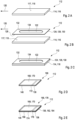
- Figures 1A to 1E show an exemplary embodiment of a method for manufacturing a test element 110.
- the test element 110 is illustrated in Figure 1E in a perspective view.
- Figures 1A to 1D different intermediate products 112 of the test element 110 are shown.
- the intermediate products 112 are illustrated in different perspective views as well.
- the substrate 114 may specifically be a flat substrate 116 having at least one flat surface 117.
- a surface of the substrate 114 may also be referred to as substrate surface 118.
- the substrate surface 118 may specifically extend along a direction of extension 120 of the substrate 114.
- the substrate 114 may at least partially be manufacturing of at least one hydrophobic material such as polyethylene terephthalate. However, other materials may be feasible.
- the substrate 114 may have an elongate shape. Exemplarily, the substrate 114 may be strip-shaped.
- At least one elongated receptacle 122 may be formed on the substrate surface 118.
- at least one foil 124 specifically at least one adhesive foil 126
- the adhesive foil 126 may be placed on the substrate 114, specifically on the substrate surface 118 of the substrate 114.
- the adhesive foil 126 may comprise at least one adhesive surface 128 facing the substrate 114, specifically the substrate surface 118 of the substrate 114.
- the adhesive foil 126 may be a double-sided adhesive foil 130.
- the double-sided adhesive foil 130 may comprise at least one further adhesive surface 132.
- the foil 124 may comprise at least one opening 134.
- the opening 134 may extend in the direction of extension 120.
- the foil 124 may have a thickness of 20 ⁇ m. However, other dimensions may be feasible.
- the foil 124 may be placed onto the substrate 114. Thereby, the foil 124 may be fixedly attached to the substrate 114 via the adhesive surface 128 of the foil 124.
- the elongate receptacle 122 may be formed, specifically by the opening 134 of the foil 124 and the surface 118 of the substrate 114.
- the elongate receptacle may have a width of 0.1 mm to 10 mm. Further, the elongate receptacle 122 may have a thickness of 70 ⁇ m. However, other dimensions may be feasible.
- At least one hydrophilic material 136 may be applied via spray coating.
- the hydrophilic material 136 may be applied on the substrate 114, specifically on the substrate surface 118. Thereby, the hydrophilic material 136 may be applied such that the elongate receptacle 122 is covered with the hydrophilic material 136 at least to a large extent.
- the hydrophilic material 136 may specifically be provided as a suspension or as a solution, and the suspension or the solution may be applied via at least one nozzle (not shown).
- the suspension or the solution may comprise at least one solvent and the solvent may evaporate during the spray coating or may be removed after conducting the spray coating via at least one drying process.
- the solvent may comprise at least one material selected from the group consisting of a polymer, a surface-active substance, a filling material, a reactive component.
- the hydrophilic material 136 may be applied such that at least one hydrophilic layer 162 is formed on the surface section 160.
- the hydrophilic layer 162 may have a thickness of 1 ⁇ m to 10 ⁇ m. However, other dimensions may be feasible.
- the hydrophilic layer 162 may be formed as a continuous hydrophilic layer 164.
- test chemical 138 is placed on the substrate 114, such that the test chemical 138 covers a partition 139 of the elongate receptacle 122.
- the test chemical 138 may be provided as a test chemical element 140.
- the test chemical element 140 may be manufactured by depositing the test chemical 138 on at least one test chemical substrate 142.
- the test chemical element 140 may be a rigid element 144 which may lay flat on the foil 124.
- the foil 124 may be a double-sided adhesive foil 130 and the test chemical element 140 may be fixedly attached to the double-sided adhesive foil 130 by the further adhesive surface 132.
- At least one cover element 146 may be placed on the substrate 114, specifically on the substrate surface 118 of the substrate 114.
- the cover element 146 may cover the elongate receptacle 122 at least partially such that a channel 148 is formed.
- the cover element 146 may specifically have a flat shape and extend along the direction of extension 120.
- the cover element 146 may specifically be a rigid element 150 and may lay flat on the foil 124.
- the foil 124 may be a double-sided adhesive foil 130, and the cover element 164 may be fixedly attached to the double-sided adhesive foil 130 via the further adhesive surface 132.
- the cover element 146 may have a shape which corresponds to a shape of the substrate 114 such as a strip shape and/or a bar shape. Further, specifically, the cover element 146 may have a width which is equivalent to the width of the substrate 114. Further, the cover element 146 may have a length which is smaller than a length of the elongate receptacle, such as by a factor of 1.7. However, other embodiments may be feasible. Specifically, the cover element may at least partially be manufactured of polyethylene glycol. Specifically, the cover element 146 may be placed adjacent to the test chemical 138.
- the channel 148 may specifically be a capillary channel 152.
- the channel 148 may comprise at least one channel surface 154.
- the at least one channel surface 154 may be formed by at least one surface selected from the group consisting of the substrate surface 118 of the substrate 114, a cover element surface 156 of the cover element 146, a receptacle surface 158 of the elongate receptacle 122.
- the receptacle surface 158 may be at least partially identical to the substrate surface 118.
- the surface section 160 may specifically be a continuous surface section 159 extending from an opening 161 of the channel 148 to the test chemical 138. At least one surface section 160 of the at least one channel surface 154 of the channel 148 may be covered with the hydrophilic material.
- the surface section 160 may be adjacent to the test chemical 138. Specifically, the surface section 160 may be part of the receptacle surface 158. Thereby, the hydrophilic material 136 may specifically be applied such that the hydrophilic material 136 forms a connection between the surface section 160 and the test chemical 138.
- the channel 148 may have a length of 10 mm to 15 mm. A fill time of the channel 148 may be smaller than 5 seconds, preferably smaller than 2 seconds, more preferably smaller than 1.5 seconds.
- Figures 2A to 2F show a further exemplary embodiment of a method for manufacturing a test element 110.
- the test element 110 may be depicted in Figure 2F , and different intermediate products 112 are illustrated in Figures 2A to 2E .
- the substrate 114 may be provided and the substrate 114 may be covered with the adhesive foil 126 comprising the opening 134.
- the adhesive foil 126 By placing the adhesive foil 126 onto the substrate 114, the elongate receptacle 122 may be formed.
- These steps may correspond at least in large parts to the steps of the method for manufacturing a test element as illustrated in Figures 1A to 1E .
- the steps as illustrated in Figures 2A to 2C may correspond to the steps as illustrated in Figures 1A to 1C .
- the test chemical 138 and the cover element 146 may be provided. Specifically, the test chemical 138 and the cover element 164 may form a single element 166. Exemplarily, the test chemical 138 and the cover element 146 may be fixedly attached to a support element 168.
- the support element 168 may specifically be provided as a flat substrate 170. Therefore, the support element 168 may comprise at least one flat surface 172 and the test chemical 138 and the cover element 146 may be fixedly attached to the support element 168 by being placed on the flat surface 142 and adjacent to each other.
- the hydrophilic material 136 may be applied to at least one surface 174 of the element 166.
- the surface 174 may comprise the cover element surface 156 and a test chemical surface 176.
- the hydrophilic layer 162 may be formed on the surface 174.
- the hydrophilic material 136 may be provided such that the hydrophilic material 136 covers the test chemical surface 176 as well.
- the surface section 160 may specifically be formed by the cover element surface and the test chemical surface.
- the cover element 146 and the test chemical 138 are placed onto the substrate 114.
- the element 166 may be placed onto the substrate 114 as one unit 178.
- the foil 124 may be the double-sided adhesive foil 130 and the element 166 may be fixedly attached to the substrate 114 via the double-sided adhesive foil 130.
- the channel 148 may be formed.
- the test chemical specifically the test chemical comprising one or more enzymes, comprises hydrophobic surfaces. This may reduce or limit a transport of the body fluid within the channel 148, specifically to the test chemical 138. Via applying or forming the hydrophilic layer 162 onto the test chemical 138, a transport of the body fluid may be accelerated.
- blood was applied as body fluid, specifically blood with a high content of hematocrit, specifically with a portion of 65 % of hematocrit.
- the hydrophilic material 136 By applying the hydrophilic material 136, the blood having a high hematocrit portion may be transported within the channel 148, specifically to the test chemical 138.
- the hydrophilic layer which may be formed on the test chemical surface comprising one or more enzymes may serve as a protection layer at the same time.
- the hydrophobic layer which may be formed as a protection layer may provide a protection against mechanical influences, specifically as the hydrophilic layer may have a flexible, porous structure which may be more stretch-resistant than the test chemical surface.
- test element 110 is shown in a cross-sectional view ( Figure 3A ) and in a top view ( Figure 3B ).
- the test element 110 as illustrated in Figures 3A and 3B corresponds at least in large parts to the test element as illustrated in Figure 1E .
- Figure 1E reference may be made to the description of Figure 1E above.
- the channel 148 may have a length of 20 mm, a width of 1.5 mm and a height of 70 ⁇ m.
- the substrate 114 and the cover element 146 may be made of polyethylene terephthalate and may have a thickness of 350 ⁇ m and 175 ⁇ m, respectively.
- the hydrophilic material may be provided as a solution comprising 2 % of polycarbonate urethane and 0.2 % of dioctyl sulfosuccinate in tetrahydrofuran.
- the hydrophilic material 136 may comprise at least one surfactant such as docusate and/or trisiloxane.
- the hydrophilic material 136 may further comprise at least one polymer.
- the surfactant docusate may be applied via spray coating with a spray time of 10 seconds. Thereby, a time how long the body fluid takes from one opening 161 of the channel 148 to the test chemical 138 was determined to 1.7 seconds. A wait time was determined to 2.27 seconds. Thereby, the term "wait time” may refer to a time for the body fluid to overcome the gap between the channel 148 and the test chemical 138.
- the surfactant trisiloxane was applied via spray coating with a spray time of 40 seconds.
- the time for transport within the channel 148 was determined to 1.27 seconds and a wait time was determined to 0.7 seconds.
- the surfactant trisiloxane was applied via spray coating with a spray time of 20 seconds. Thereby, the time for transport through the channel was determined to 0.99 seconds, and a wait time was determined to 0.29 seconds.
- the surfactant trisiloxane was applied via spray coating with a spray time of 2 seconds. Thereby, a time for transport of the body fluid within the channel 148 was determined to 0.67 seconds. On the contrary, during a reference measurement wherein no surfactant or hydrophilic material was applied, the time of transport of the body fluid within the channel 148 was determined to 4.53 seconds.
- an additional aluminum oxide foil may be applied.
- the hydrophilic material may be applied such that the channel and the test chemical is covered with the hydrophilic material within one step and a transfer of the body fluid to the test chemical may be feasible, thus allowing to considerably reduce the wait time, such as down to a value of 0.29 s.
- the fill time refers to the time required to fill the channel with the body fluid. Without application of a hydrophilic material on the channel surface at all, the fill time was determined as 5.04 seconds. On the contrary, by applying the hydrophilic material, the fill time was determined as 4.78 seconds.
- the hydrophilic material may comprise at least one polymer, such as polycarbonate urethane.
- the polymer may have a surface which corresponds to fleece and may lead to an improvement of a wetting as well as of the fill time.
- the test element 110 may be manufactured as a roll good 180.
- the adhesive foil 126 (not shown in Figure 3B ) as well as the test chemical 138 and the cover element 146, may be placed on top of the surface 114 and the substrate 114 may provide space for several units of the test chemical 138 such that a plurality of test elements 110 may be generated by cutting the substrate 114 into distinct pieces. Consequently, an assembly comprising the substrate 114, the adhesive foil 126, the test chemical 138 and the cover element 146 may be manufactured as a roll and may be cut into individual test elements 110 thereafter.
- test element 110 in Figures 4A to 4B , a further exemplary embodiment of a test element 110 is shown in a cross-sectional view ( Figure 4A ) and in a top view ( Figure 4B ).
- the test element 110 as illustrated in Figure 4A and 4B corresponds at least in large parts to the test element 110 as illustrated in Figure 2F .
- the hydrophilic material 136 may comprise Bindzil and Tylose.
- a fill time or a time for transport of the body fluid within the channel 148 was determined to 1.1 seconds, and the wait time was determined to 0.85 seconds.
- Figure 4B a top view of the test element 110 is shown. Therein, the test chemical 138 is illustrated. The test chemical 138 and the cover element 146 cover the elongate receptacle 122. A transport of a body fluid 182 within the channel 148 was monitored.
- FIGs 5A to 5C a further method for manufacturing a test element for detecting at least one analyte in a body fluid is illustrated.
- the test element is shown in a perspective view.
- FIGs 5A and 5B different intermediate products 188 are shown.
- At least one substrate 190 is provided.
- the substrate 190 may have at least one elongate receptacle 192.
- the elongate receptacle 192 may be stamped into the substrate 190.
- the substrate 190 may specifically be an embossed foil 193.
- at least one test chemical 194 may be placed within the elongate receptacle 192.
- at least one foil 196 may be placed into the receptacle.
- the foil 196 may form a bottom 198 of the elongate receptacle 192.
- test chemical 194 may be provided as fine cut 200. Further, the test chemical 194 may be either placed into the elongate receptacle 192 or adhered to the elongate receptacle 192, specifically to the foil 196 via at least one adhesive material (not shown).
- At least one hydrophilic element 202 may be placed on the substrate 190.
- the hydrophilic element 202 may be placed on the substrate 190 such that at least one gap 212, as illustrated in Figure 5B , between the test chemical 194 and at least one surface 114 of the elongate receptacle 192 is filled with the hydrophilic element 202.
- the hydrophilic element 102 may be provided as a foil 216.
- the hydrophilic element 202 may be coated with at least one hydrophilic layer 218 at least partially. Specifically, the coating of the hydrophilic element 202 may be conducted such that gaps (not shown) within the hydrophilic element 202 may be reduced at least to a large extent.
- FIGs 6A to 6C a further exemplary embodiment of a method for manufacturing a test element is illustrated.
- the test element 186 is illustrated in Figure 6C in a cross-sectional view, and in Figures 6A and 6B different intermediate products 188 are shown.
- the substrate 190 is provided.
- the foil 196 and the test chemical 194 may be placed onto the substrate 190.
- the hydrophilic element 202 which may specifically be provided as foil 222 may be placed onto the substrate, thereby covering the test chemical 194 and the foil 196.
- a hydrophilic grid 224 may be placed onto the hydrophilic element 202.
- a channel 226 may be formed, specifically via laser welding or gluing.
- Figure 7A shows a relative remission Re in dependence of time t and Figure 7B shows the corresponding difference of remission ⁇ Re for different thicknesses of the hydrophilic layer which was applied via blanket coating in this particular embodiment.
- the data were acquired via a measuring device comprising an UV-LED and a detector and enzymatic reactions were monitored.
- Curves A correspond to a sample wherein no hydrophilic material was applied.
- Curves B correspond to a sample, wherein 0.03 g/m 2 of Tylose and 0.72 g/m 2 of Bindzil CC301 were applied leading to a hydrophilic layer with a thickness of 30 ⁇ m.
- Curves C correspond to a sample, wherein 0.05 g/m 2 of Tylose and 1.44 g/m 2 of Bindzil CC301 were applied leading to a hydrophilic layer with a thickness of 60 ⁇ m.
- Curves D correspond to a sample, wherein 0.10 g/m 2 of Tylose and 2.88 g/m 2 of Bindzil CC301 were applied leading to a hydrophilic layer with a thickness of 120 ⁇ m. It can be demonstrated that deviations in the kinetics are small. Consequently, applying a hydrophilic layer on the test chemical does not have a significant influence on a performance, i.e. there is no significant influence on kinetics.
Description
- The methods and devices according to the present invention may be used for detecting at least one analyte present in one or both of a body tissue or a body fluid, in particular the method and devices may be applied in the field of detecting one or more analytes such as glucose, lactate, triglycerides, cholesterol or other analytes, preferably metabolites, in body fluids such as blood, preferably whole blood, plasma, serum, urine, saliva, interstitial fluid or other body fluids, both in the field of professional diagnostics and in the field of home monitoring. However, other fields of application are feasible.
- In the field of medical technology and diagnostics, a large number of devices and methods for detecting at least one analyte in a body fluid are known. The method and devices may be used for detecting at least one analyte present in one or both of a body tissue or a body fluid, in particular one or more analytes such as glucose, lactate, triglycerides, cholesterol or other analytes, preferably metabolites, in body fluids such as blood, preferably whole blood, plasma, serum, urine, saliva, interstitial fluid or other body fluids. Further devices are known for measuring activating times, e.g. a thrombin activation time measurement for coagulation monitoring. Without restricting the scope of the present invention, in the following, mainly reference is made to the determination of glucose as an exemplary and preferred analyte.
- The determination of blood glucose concentration as well as a corresponding medication is an essential part of daily routine for many diabetics. In order to increase convenience and in order to avoid restricting the daily routine by more than a tolerable degree, portable devices and test elements are known in the art, such as for measuring blood glucose concentration during work, leisure or other activities away from home. In the meantime, many test devices are commercially available. A large number of test devices and test systems are known which are based on the use of test elements in the form of test strips. Applications are known, in which a multiplicity of test strips is provided by a magazine, wherein a test strip from the magazine automatically may be provided to the testing device. Other applications, however, are known in which single test strips are used, which are inserted into the testing device manually by a user. Therein, typically, the end of the test strip is adapted to be inserted into the testing device and for detecting the analyte, wherein the opposing end of the test strip serves as a handle enabling the user to push the test strip into the testing device or to remove the test strip from the testing device. For applying the sample to the test element, typical test elements provide at least one sample application site, such as a capillary opening in capillary test elements or a sprite net in optical test strips having a top dosing system. Test strips of this type are commercially available, e.g. under the trade name Accu-Chek Active®. Alternatively to home care applications, such test elements may be used in professional diagnostics, such as in hospital applications.
- In many cases, for detecting the analyte, test elements are used, such as test strips, which comprise one or more test fields having one or more test chemistries. The test chemistries are adapted to change one or more detectable properties in the presence of the analyte to be detected. Thus, electrochemically detectable properties of the test chemistry and/or optically detectable properties of the test chemistry may be changed due to the influence of the presence of the analyte. For potential test chemistries which may be used within the present invention, reference may be made to J. Hönes et al.: Diabetes Technology and Therapeutics, Vol. 10, . However, other types of test chemistries may be used within the present invention.
- Exemplarily, the detection of the at least one analyte can be performed by using an electrochemical test element. Commonly used are disposable electrochemical capillary sensor test elements. Such test elements typically comprise at least one working electrode for detecting the analyte as well as at least one counter electrode to support a current flow through a measuring cell of the test element. In addition, optionally, the test element may comprise at least one reference electrode. In alternative embodiments, a reference electrode may be designed individually and/or may be combined with the counter electrode. However, other types of measurement setups are possible, in order to derive an analyte concentration from a comparison of electrode potentials.
- Commonly, the test elements may be comprise several layers, the layers being manufactured by a combination of conventional methods such as dip coating or laminating individual foils.
- In
WO 2006/017358 A1 systems and methods for measuring an analyte in a host are described. More particularly, the present invention relates to systems and methods for transcutaneous measurement of glucose in a host. The transcutaneous analyte sensor system can include an applicator, a mounting unit, an electronics unit, a base adapted for mounting on a skin of a host, and one or more contacts configured to provide electrical contact between the sensor and the electronics unit. - In
EP 2681329 A1 a method for producing a test element for studying a body fluid sample is described. The detection layer is covered with a polymeric spread layer and applied to a support. According to the invention it is provided that the spread layer is produced by being sprayed onto the detection layer. The invention further elates to such a test element having a spread layer that has a thickness of at most 20 µm. - In
EP 1 035 919 B1 a device for the capillary transport of a liquid between two opposite lying, essentially planar layers is described. Both layers are arranged at a distance from and parallel to one another in such a way that a capillary active gap is created between both layers. The invention is characterized in such a way that at least one of the layers comprises at least two discrete adjacent parts, and that the capillary active transport of the liquid can flow beyond the common boundary of the parts which are situated in a layer. - In
EP 2 144 061 A1 an electrochemical sensor for determining a coagulation parameter is described. The coagulation parameter comprises a carrier; at least two electrodes, which are applied on the carrier; at least one test reagent; and a surfactant-containing coating. Independent claims are included for: (1) coating a sensor film with a surfactant-solvent mixture, comprising applying the surfactant-solvent mixture by piezo-printing; (2) preparing the electrochemical sensor, comprising providing a carrier, applying at least two electrodes on the carrier, applying at least one test reagent, applying a surfactant-solvent mixture and affixing a lid, thus a capillary sensor element is formed; and (3) electrochemical test element analysis system, comprising the electrochemical sensor and at least a current- or voltage meter. -
US 2016/082434 discloses a method of manufacturing a test element for detecting at least one analyte in a body fluid comprising providing at least one substrate having at least one elongate receptacle; placing one test chemical on the substrate; placing one cover element on the substrate. It also anticipates the method of using said test element for detecting one analyte in a body fluid. - Despite of the advantages and the progress achieved by the above-mentioned developments, some significant technical challenges remain. Conventional production methods, specifically conventional production methods such as dip coating or laminating individual foils generally imply a number of limitations when it comes to producing defined three-dimensional multi-layered structures, producing thin layers, specifically thin layers with a thickness of smaller than 10 µm, producing test elements with several adjacent, functionalized areas, wherein the areas are specifically smaller than 1 mm2, producing sequences of layers having components which are not stable in a dissolved status or in a moist status as they would react with each other, manufacturing layers which are stable at temperatures which exceed room temperatures or producing layers having a three-dimensional structures, e.g. comprising pores and cavities.
- It is therefore an objective of the present invention to provide a method for manufacturing a test element for detecting at least one analyte in a body fluid, a test element for detecting at least one analyte in a body fluid, a method for detecting at least one analyte in a body fluid, a system for detecting at least one analyte in a body fluid and a method for manufacturing a test element for detecting at least one analyte in a body fluid which at least partially avoid the shortcomings of known devices and methods of this kind and which at least partially address the above-mentioned challenges. Specifically, methods shall be disclosed which allow for easy manufacturing of test elements.
- This problem is solved by a method and a device for a method for manufacturing a test element for detecting at least one analyte in a body fluid, a test element for detecting at least one analyte in a body fluid, a method for detecting at least one analyte in a body fluid, a system for detecting at least one analyte in a body fluid and a method for manufacturing a test element for detecting at least one analyte in a body fluid with the features of the independent claims. Preferred embodiments, which might be realized in an isolated fashion or in any arbitrary combination, are listed in the dependent claims.
- As used in the following, the terms "have", "comprise" or "include" or any arbitrary grammatical variations thereof are used in a non-exclusive way. Thus, these terms may both refer to a situation in which, besides the feature introduced by these terms, no further features are present in the entity described in this context and to a situation in which one or more further features are present. As an example, the expressions "A has B", "A comprises B" and "A includes B" may both refer to a situation in which, besides B, no other element is present in A (i.e. a situation in which A solely and exclusively consists of B) and to a situation in which, besides B, one or more further elements are present in entity A, such as element C, elements C and D or even further elements.
- Further, it shall be noted that the terms "at least one", "one or more" or similar expressions indicating that a feature or element may be present once or more than once typically will be used only once when introducing the respective feature or element. In the following, in most cases, when referring to the respective feature or element, the expressions "at least one" or "one or more" will not be repeated, non-withstanding the fact that the respective feature or element may be present once or more than once.
- Further, as used in the following, the terms "preferably", "more preferably", "particularly", "more particularly", "specifically", "more specifically" or similar terms are used in conjunction with optional features, without restricting alternative possibilities. Thus, features introduced by these terms are optional features and are not intended to restrict the scope of the claims in any way. The invention may, as the skilled person will recognize, be performed by using alternative features. Similarly, features introduced by "in an embodiment of the invention" or similar expressions are intended to be optional features, without any restriction regarding alternative embodiments of the invention, without any restrictions regarding the scope of the invention and without any restriction regarding the possibility of combining the features introduced in such way with other optional or non-optional features of the invention.
- In a first aspect of the present invention, a method for manufacturing a test element for detecting at least one analyte in a body fluid is disclosed. The method comprises the method steps as given in the independent claim and as listed as follows. The method steps may be performed in the given order. However, other orders of the method steps are feasible. Further, one or more of the method steps may be performed in parallel and/or on a timely overlapping fashion. Further, one or more of the method steps may be performed repeatedly. Further, additional method steps may be present which are not listed.
- The method for manufacturing a test element for detecting at least one analyte in a body fluid comprises the following steps:
- a) providing at least one substrate having at least one elongate receptacle on a substrate surface of the substrate;
- b) placing at least one test chemical on the substrate in a manner that the test chemical covers a partition of the elongate receptacle;
- c) placing at least one cover element on the substrate such that the cover element covers the elongate receptacle at least partially, whereby a channel having a channel surface is formed; wherein at least one hydrophilic material is applied in a manner that at least one surface section of the channel surface is covered with the hydrophilic material, wherein the surface section is adjacent to the test chemical, wherein the cover element is placed adjacent to the test chemical, characterized in that a hydrophilic layer is applied in an area of a gap between the test chemical and the cover element.
- As further used herein, the term "manufacturing" may refer to an arbitrary process of producing or assembling an arbitrary device, specifically in a mechanical way. Specifically, the term manufacturing may refer to a value added production of a device for use. For the process of manufacturing machines, tools, chemical and biological processing or formulation may be applied. The manufacturing process may comprise a number of different manufacturing steps which may be performed in a given order. However, one or more of the manufacturing steps may be performed in parallel and/or on a timely overlapping fashion. Further, one or more of the manufacturing steps may be performed repeatedly. Exemplarily, the manufacturing process may begin with a creation of materials from which a device is made. These materials may then be modified through the manufacturing process to become the desired device. Further, exemplarily, the device may be assembled by combining several separate components. However, other embodiments may be feasible.
- As further used herein, the term "test element" may refer an arbitrary device which is capable of detecting the analyte in a sample or of determining at least one parameter of the sample. The test element may therefore have at least one receptacle which is configured to receive the sample. Further, the test element may have at least one test field wherein the detection of the analyte in the sample or the determination of the at least one parameter occurs. Exemplarily, the test field may comprise at least one test chemistry which will further be described below in more detail. The test element may be an arbitrary monolithic device or an arbitrary one-piece device. Specifically, the test element may be a strip-shaped test element. As used herein, the term "strip-shaped" refers to an element having an elongated shape and a thickness, wherein an extension of the element in a lateral dimension exceeds the thickness of the element, such as by at least a factor of 2, preferably by at least a factor of 5, more preferably by at least a factor of 10 and most preferably by at least a factor of 20 or even at least a factor of 30. Thus, the test element may also be referred to as test strip.
- The term "analyte" may generally refer to an arbitrary element, component or compound which may be present in the sample and the presence and/or the concentration of which may be of interest for the user, the patient or medical staff such as a medical doctor. Particularly, the analyte may be or may comprise an arbitrary chemical substance or chemical compound which may take part in the metabolism of the user or the patient, such as at least one metabolite. The detection of the at least one analyte specifically may be an analyte-specific detection.
- As further used herein, the term "body fluid" may refer to a fluid which typically is present in a body or body tissue of the user or the patient and/or which may be produced by the body of the user or the patient. As an example for body tissue, interstitial tissue may be named. Thus, as an example, the body fluid may be selected from the group consisting of blood and interstitial fluid. However, additionally or alternatively, one or more other types of body fluids may be used, such as saliva, tear fluid, urine or other body fluids. During detection of the at least one analyte, the body fluid may be present within the body or body tissue. Thus, specifically, as will be outlined in further detail below, the sensor may be configured for detecting at least one analyte in a body tissue.
- The term "detecting" may generally refer to a process of determining a presence and/or a quantity and/or a concentration of the at least one analyte. Thus, the detection may be or may comprise a qualitative detection, simply determining a presence of the at least one analyte or a absence of the at least one analyte, and/or may be or may comprise a quantitative detection, which determines the quantity and/or the concentration of the at least one analyte. As a result of the detection, at least one signal may be produced which characterizes an outcome of the detection, such as at least one measurement signal. The at least one signal specifically may be or may comprise at least one electronic signal such as at least one voltage and/or at least one current. The at least one signal may be or may comprise at least one analogue signal and/or may be or may comprise at least one digital signal. Therefore, the detection may be conducted via at least one sensor. The term "sensor" may generally refer to an arbitrary element which is adapted to perform a process of detection and/or which is adapted to be used in the process of detection. Thus, the sensor specifically may be adapted to determine the concentration of the analyte and/or a presence of the analyte. The sensor may be part of a measurement device or analytical device as will further be described below in more detail.
- As described above, the at least one substrate is provided. The term "substrate" may refer to an arbitrary element which is suitable to carry one or more other elements disposed thereon or therein. As an example, the substrate may be a flat substrate, such as a substrate having a lateral extension exceeding its thickness by at least a factor of 2, at least a factor of 5, at least a factor of 10, or even at least a factor of 20 or more. The substrate specifically may have an elongated shape, such as a strip-shape and/or a bar-shape.
- The substrate may be at least partially manufactured of at least one hydrophobic material. As further used herein, the term "hydrophobic" may refer to a physical property of a molecule, specifically of a molecule of an arbitrary solid element or of an arbitrary fluidic medium, of being repelled form a mass of water. Generally, hydrophobic molecules tend to be nonpolar and, thus, prefer other neutral molecules and nonpolar solvents. Because water molecules are polar, the hydrophobic molecules do not dissolve well among them. The hydrophobic molecules in water often cluster together, forming micelles. Water on hydrophobic surfaces may exhibit a high contact angle. In contrast, hydrophilic molecules are generally attracted to water as will further be described below in more detail. Specifically, the substrate may be manufactured of at least one polymer, specifically of at least one thermoplastic polymer. Preferably, the substrate may be manufactured of at least one of polyethylene terephthalate; polycarbonate; polystyrene; polyvinyl chloride; polypropylene; poly(methyl methacrylate); polyurethane; polyester; acrylonitrile butadiene styrene; polymer blends. However, other materials may also be feasible.
- As described above, the substrate has at least one elongate receptacle on the substrate surface. As further used herein, the term "receptacle" may refer to an arbitrary element of an object which is configured to receive or to hold something. Therefore, the receptacle may have or may be embodied as a recess or as a cavity of the object. Further, the term "elongate receptacle" may refer an arbitrary receptacle wherein an extension of the receptacle in a lateral dimension exceeds a width of the elongate receptacle, such as by at least a factor of 2, preferably by at least a factor of 5, more preferably by at least a factor of 10 and most preferably by at least a factor of 20 or even at least a factor of 30. The elongate receptacle may specifically have a length of 3 mm to 50 mm, preferably of 5 mm to 30 mm, more preferably of 10 mm to 20 mm, most preferably of 12 mm. Further, the elongate receptacle may have a width of 0.1 mm to 10 mm, preferably a width of 0.5 mm to 5 mm, more preferably a width of 1 mm to 2 mm. Moreover, the elongate receptacle may have a thickness of 20 µm to 100 µm, preferably of 30 µm to 90 µm, more preferably of 50 µm to 80 µm, most preferably of 70 µm.
- The elongate receptacle may be formed on the substrate surface. The term "forming" may refer to an arbitrary process of making or constructing something. Thereby, exemplarily, several components may be assembled in such a way that a desired feature may emerge. However, other embodiments may be feasible. Specifically, the elongate receptacle may be formed by placing at least one foil, specifically at least one adhesive foil, on the substrate. The adhesive foil may exemplarily be a double-sided adhesive foil. Exemplarily, the foil may comprise at least one opening extending in a direction of extension of the foil and the elongate receptacle may be formed by the opening. The foil may have a thickness of 20 µm to 100 µm, preferably of 30 µm to 90 µm, more preferably of 50 µm to 80 µm, most preferably of 70 µm. However, other embodiments may be feasible. Exemplarily, the elongate receptacle may be formed by generating a groove directly into the substrate. Further, additionally or alternatively, the substrate may be manufactured with the elongate receptacle such as via injection molding. However, also other embodiments may be feasible.
- In a further step, as described above, the at least one test chemical is placed on the substrate. As further used herein, the term "test chemical" also referred to as test chemistry, may refer to an arbitrary material or a composition of materials adapted to change at least one detectable property in the presence of the analyte. Generally, this property may be selected from an electrochemically detectable property and/or an optically detectable property, such as a color change and/or a change in remissive properties. Specifically, the test chemical may be a highly selective test chemical, which only changes the property if the analyte is present in the sample of the body fluid applied to the test element, whereas no change occurs if the analyte is not present. More preferably, the degree or change of the property may be dependent on the concentration of the analyte in the body fluid, in order to allow for a quantitative detection of the analyte.
- As an example, the test chemical may comprise at least one enzyme, such as glucose oxidase and/or glucose dehydrogenase. Additionally or alternatively, the test chemical may comprise one or more co-enzymes and/or one or more mediators. Further, alternatively or additionally, the test chemical may comprise one or more dyes, which, preferably in interaction with the one or more enzymes, may change their color in the presence of the at least one analyte to be detected.
- The test chemical may be configured for performing at least one of an electrochemical detection reaction and an optically detectable detection reaction. The electrochemical detection reaction and the optically detectable detection reaction may be analyte specific. Further, the electrochemical detection reaction and the optically detectable detection reaction may be a qualitative and/or a quantitative detection. As used herein, the term "optically detectable detection reaction" refers to a detection of an optical detectable property of the analyte itself or an auxiliary compound which is produced or converted with a detection reaction depending on the presence and/or concentration of the analyte in the sample, such as a color change and/or a change in remissive properties.
- Exemplarily, the test chemical may form a layer on the substrate. Specifically, the test chemical may be provided on the substrate via spray coating. However, other methods for generating a layer on a substrate may be feasible. Further, additionally or alternatively, the test chemical may be provided as a test chemical element. The test chemical element may exemplarily be manufactured by depositing the test chemical on at least one test chemical substrate. Thereby, the test chemical substrate and the test chemical may form the test chemical element and the test chemical element may be placed onto the substrate. However, other embodiments may be feasible.
- As described above, the test chemical is placed in a manner that the test chemical covers the partition, e.g. a part, of the elongate receptacle. Thereby, the term "covering" may refer to a process wherein the test chemical, specifically when provided as test chemical element, is placed over the elongate receptacle. Thus, the test chemical may rest on the substrate such as on the adhesive foil. Specifically, the test chemical may be fixedly attached to the adhesive foil. Additionally or alternatively, the test chemical may be received within the elongate receptacle such as being in direct contact with a surface of the elongate receptacle. This may specifically be the case when the test chemical is provided as a layer via spray coating as described above or as a flexible foil. However, other embodiments may be feasible.
- In a further step, as described above, the at least one cover element is placed on the substrate. As further used herein, the term "cover element" may refer to an arbitrary element which is suitable to be or to serve as a covering for another object or the like, especially for covering at least a partition of the elongate receptacle. Specifically, the cover element may be configured to serve as a protection, in particular, from environmental influences and/or to seal the other object or the like from environmental influences. As an example, the cover element may have at least one flat surface. The flat surface may be configured to serve as a contact area or support areas. The cover element may further have a lateral extension exceeding its thickness by at least a factor of 2, at least a factor of 5, at least a factor of 10, or even at least a factor of 20 or more. The cover element may have a shape which corresponds to a shape of the substrate as described above. The cover element specifically may have an elongated shape, such as a strip-shape and/or a bar-shape. Further, specifically, the cover element may have a width with is equivalent to the width of the substrate. Further, the cover element may have a length which is smaller than a length of the elongate receptacle, such as by at least a factor of 0.9, preferably by at least a factor of 0.8, more preferably by at least a factor of 0.7 and most preferable by at least a factor of 0.5. However, other embodiments may be feasible. Further, the cover element may have a thickness of 10 µm to 200 µm, preferably of 30 µm to 150 µm, more preferably of 50 µm to 100 µm. Further, the cover element may have a width of 1 mm to 20 mm, preferably of 3 mm to 12 mm, more preferably of 4 mm to 6 mm and most preferably of 5 mm. As an example, the cover element may be a cover foil. Specifically, the cover foil may be at least partially manufactured of polyethylene terephthalate; polycarbonate; polystyrene; polyvinyl chloride; polypropylene; poly(methyl methacrylate); polyurethane; polyester.
- Further, as described above, the cover element covers the elongate receptacle at least partially, preferably partially, by which a channel is formed. As further used herein, the term "channel" may refer to arbitrary element of an object which is configured to enable a transport of an arbitrary medium such as a fluidic medium within the element, such as from one end of the element to another end of the element. The channel may have an interior volume which may be fully or at least partially enclosed or surrounded by a wall of the object. Therefore, a flow of a fluid medium or an insertion of another object from one end of the element to a further end through the interior volume may be feasible. As further used herein, the term "wall" may refer to an arbitrary structure, specifically a structural material, which is configured to at least partially surround another object or volume thereby defining physical limits of an object. Further, the wall may be configured to protect the interior volume or the other object at least partially enclosed by the wall. The channel may specifically have an elongate shape, e.g. an extension of the channel in a lateral dimension may exceeds a width of the channel, such as by at least a factor of 2, preferably by at least a factor of 5, more preferably by at least a factor of 10 and most preferably by at least a factor of 20 or even at least a factor of 30.
- Specifically, the channel may be a capillary channel, also referred to as capillary. As used herein, the term "capillary channel" may refer to an element which is adapted to receive a sample of a fluidic medium and/or to transport the sample of the fluidic medium by capillary forces. The capillary channel may comprise at least one volume configured to receive the fluidic medium, e.g. via one or more capillary caps and/or via one or more capillary slots and/or one or more capillary tubes having an arbitrary cross-section, such as a rectangular cross-section Specifically, the capillary channel may be configured to receive the sample of the body fluid and/or transport the sample of the body fluid by the capillary forces and/or a round cross-section and/or a polygonal cross-section.
- Further, the channel has a channel surface, e.g. a surface of the channel. Specifically, the at least one channel surface of the channel may be formed by at least one surface selected from the group consisting of a substrate surface of the substrate; a cover element surface of the cover element; a receptacle surface of the elongate receptacle. The receptacle surface and the substrate surface may be at least partially identical to each other. Exemplarily, the elongate receptacle may be formed by the substrate and the adhesive foil having the opening as described above. Thus, the at least one surface of the channel may be formed by the substrate surface, the cover element surface and a foil surface of the adhesive foil. Further, exemplarily, the elongate receptacle may be formed as a groove within the substrate as described above. Thereby, the substrate surface may be at least partially identical to the receptacle surface. Further, the method for manufacturing a test element may comprise further steps of coating at least one of the cover element surface, the receptacle surface, the substrate surface such with further layers are generated or of placing further elements such as foils, membranes or the like on the at least one of the cover element surface, the receptacle surface, the substrate surface. Thereby, the at least one surface of the channel may also be formed by at least one surface of the further layers or of the further elements such as of the foils.
- In an embodiment of the present invention, the channel may be formed by cutting the cover foil and the adhesive foil to a similar length, thus allowing the channel to be filled with a sample of the body fluid applied by side filling. In an alternative embodiment of the present invention, the channel may be formed by cutting the cover foil shorter than the adhesive foil, thus allowing the channel to be filled with a sample of the body fluid applied by top filling. However, further embodiments may also be feasible.
- As described above, the at least one hydrophilic material is applied via spray coating in a manner that at least one surface section between the test chemical and the channel surface is covered with the hydrophilic material. As further used herein, the term "hydrophilic" may refer to a property of an arbitrary molecule or of an arbitrary molecular entity or of an arbitrary material of being attracted to water molecules and of being at least to a large extend dissolvable by water. Generally, a hydrophilic molecule or a portion of the hydrophilic molecule may be able to interact with water and other polar substances in a more thermodynamically favorable way than to interact with oil or other hydrophobic solvents. The hydrophobic molecules may typically be charge-polarized and capable of hydrogen bonding. The hydrophilic molecules can be contrasted with hydrophobic molecules. In some cases, both hydrophilic and hydrophobic properties occur in a single molecule.
- The hydrophilic material may be provided as a suspension or as a solution. The term "suspension" may refer to a heterogeneous mixture comprising at least one medium, specifically at least one fluidic medium, as well as particles, specifically solid particles, that are sufficiently large for sedimentation. The particles may specifically be larger than one micrometer. Thus, the particles do not dissolve but get suspended throughout a bulk of the fluid medium. Generally, the particles may be visible by eye. Suspensions can generally be classified on basis of a dispersed phase and a dispersion medium, wherein the dispersed phase is essentially solid, e.g. fully or partially solid, while the dispersion medium may either be a solid, a liquid, or a gas. Suspensions may be unstable from a thermodynamic point of view; however, suspensions can be kinetically stable over a large period of time, which determines a shelf life. Further, the term "solution" may generally refer to a homogeneous mixture comprising two or more substances. The solution may specifically comprise at least one solvent and at least one solute. Thereby, the term "solute" may refer to an arbitrary substance which is dissolved in another substance. The solution may at least to a large extend have properties, specifically physical properties, which correspond to properties of the solvent including a phase. Commonly, the solvent may be a major fraction of the mixture. The concentration of a solute in a solution is a measure of how much of that solute is dissolved in the solvent, with regard to how much solvent is present like salt.
- Specifically, the suspension or the solution may comprise at least one solvent. The term "solvent" may refer to an arbitrary substance that dissolves a solute, e.g. a chemically distinct liquid, solid or gas, resulting in a solution. A solvent may usually be a liquid but can also be a solid or a gas. A quantity of solute that can usually dissolve in a specific volume of solvent varies with temperature. Exemplarily, the solvent may evaporates while the spray coating is conducted. However, additionally or alternatively, the solvent may be removed after conducting the spray coating via at least one drying process.
- The hydrophilic material may comprise at least one material selected from the group consisting of a polymer; a surface-active substance, a filling material, a dye, and a reactive component. Specifically, the polymer may be selected from the group consisting of cellulose, polyethylene glycol, polyvinyl alcohol, polyolefin, polyurethane, polyamide, polyimide, polyacrylate, polycarbonate, polyester, polyether, polyvinyl ether, polyvinyl ester, polyvinyl alcohol, and polysiloxane.
- Further, the surface-active substance may be a surfactant, specifically a hydrophilic surfactant, specifically an anionic surfactant. As further used herein, the term "surfactant" may refer to an arbitrary molecule is configured to lower a surface tension or interfacial tension between two liquids or between a liquid and a solid. The surfactant may be an organic compound that is amphiphilic, e.g. having hydrophobic groups and hydrophilic groups. Therefore, the surfactant may comprise both a water-insoluble component and a water-soluble component. The surfactant may be configured to diffuse in water and adsorb at interfaces between air and water or at an interface between oil and water, in case where water is mixed with oil. A water-insoluble hydrophobic group may extend out of a bulk water phase, into the air or into the oil phase, while the water-soluble head group may remain in the water phase.
- As further used herein, the term "spray coating" may refer to an arbitrary process wherein an arbitrary material is deposited onto a surface by spraying. For this purpose, the material may specifically be provided in a fluid form, exemplarily as a suspension or as a solution. Further, the material may be accelerated towards the surface in form of particles, specifically in form of micrometer-sized particles. Exemplarily, the suspension or the solution may be applied via at least one nozzle, specifically via at lest one compressed air nozzle. Typically, a coating or a layer of the material may be generated by an accumulation of a plurality of the particles. A solvent of the material may evaporate at least to a large extend during the spray coating and/or after the spray coating such as in a separate drying process. However, other methods may also be feasible for applying the hydrophilic material such as blanket coating. The term "blanket coating" may refer to an arbitrary process, wherein one or more coating materials are distributed on a surface via one or more doctor blades or doctor knifes.
- As further used herein, the term "surface section" may refer to a part, specifically to a distinct part, of a surface. Exemplarily, the term surface section may refer to at least 5%, at least 10%, at least 20%, at least 30%, at least 40%, at least 50%, at least 60%, at least 70%, at least 80%, at least 90%, at least 95%. However, other embodiments may be feasible. Further, the term surface section may refer to a whole surface, e.g. to 100% of the surface. As the at least one channel surface may be formed by at least one surface selected from the group consisting of the substrate surface; the cover element surface; the receptacle surface, the surface section may be part of or may be the cover element surface, the receptacle surface and/or the substrate surface. However, the surface section may be part of or may be the at least one surface of the further layers or of the further elements such as of the foils as outlined above. Specifically, the surface section may be a continuous surface section. Thereby, the continuous surface section may extend form an opening of the channel which is configured to receive the sample of the body fluid to the test chemical. Exemplarily, the continuous surface section may be part of the receptacle surface. Specifically, the continuous surface section may correspond to at least 60%, preferably to at least 70%, more preferably to at least 80%, more preferably to at least 90%, most preferably to at least 95% of the receptacle surface. Specifically, the continuous surface section may be equivalent to the receptacle surface, e.g. the continuous surface section may correspond to 100% or at least to almost 100% of the receptacle surface. Further, exemplarily, the continuous surface section may correspond to at least 60%, preferably to at least 70%, more preferably to at least 80%, more preferably to at least 90%, most preferably to at least 95% of the cover element surface. Specifically, the continuous surface section may be equivalent to the cover element surface, e.g. the continuous surface section may correspond to 100% or at least to almost 100% of the cover element surface.
- The term "adjacent" may generally refer to a property of an arbitrary element of being in proximity of another element. The term "adjacent" may also be referred to as "contiguous", "adjoint", "besides" or further related terms. Consequently, the element and the other element may be arranged in a neighboring fashion with respect to each other. Exemplarily, the element and the other element may be located in a plane and thus, the element and the other element may be arranged next to each other. Further, exemplarily, the element and the other element may be arranged opposite to each other. Thereby, at least one surface of the element and at least one surface of the other element may face each other. However, other embodiments may be feasible. The element and the other element may be in direct contact to each other, e.g. touch each other. Further, the term "adjacent" may also include that the element and the other element are arranged in an overlapping fashion. However, the element and the other element may be arranged in a distance to each other, e.g. may not touch each other. Specifically, the test chemical and the surface section may be located in one plane and thus, the test chemical and the surface section may be arranged next to each other. Thereby, the surface section may specifically be part of or may be the cover element surface. Specifically, the hydrophilic material may be applied such that the hydrophilic material forms, e.g. generates or establishes, a connection between the surface section and the test chemical. As further used herein, the term "connection" may refer to a link or a conjunction of two or more elements. Exemplarily, the hydrophilic material may exemplarily form a layer as will further be described below in more detail and the layer may be arranged between the test chemical and the surface section. Specifically, the layer may touch, e.g. be in direct contact with, at least one of the test chemical and the surface section. Thus, the connection may also be referred to as a "bridge". Further, the surface section may be part of or may be the receptacle surface and the hydrophilic material may be applied such that the hydrophilic material forms a connection between the surface section and the test chemical. Thereby, the test chemical may specifically in direct contact with the receptacle surface such as being at least partially received in the receptacle surface. Further, the hydrophilic material may also be applied such that the hydrophilic material forms a layer on the test chemical. Thus, the a hydrophilic layer may be formed which covers at least parts of the test chemical surface as well as at least parts of the receptacle surface and/or the cover element surface at the same time.
- Herein, the hydrophilic layer may be a non-porous layer or a porous layer having a plurality of pores within the layer. The porous property of the hydrophilic layer may, in particular, be useful for advancing the transport of the body fluid to the test chemical. Especially, the porous hydrophilic layer may have a plurality of pores having an average pore size of 1 µm to 500 µm, preferably of 2 µm to 200 µm and most preferably of 5 µm to 100 µm. A pore size distribution may be adjustable by one or more parameters of the spray coating such as a spraying period, a concentration of the material provided as suspension or as solution, a design of the nozzle, a design of an opening of the nozzle, a distance between the nozzle and the substrate as well as an applied spray pressure. Specifically, an increase of the concentration may lead to an increased layer thickness and to smaller pore sizes. Further, an increase of the spraying period a number of layers lying on each other may increase.
- Further, alternatively or additionally, the test chemical and the surface section may be arranged opposite to next other. Thereby, the surface section may specifically be part of or may be the receptacle surface and/or the substrate surface. The substrate surface may be at least partially identical to the receptacle surface. Thereby, the surface section may be arranged in a distance to the test chemical or may be in direct contact with the test chemical. In a particularly preferred embodiment, the distance between the substrate surface and the test chemical may be arranged in a manner that the capillary channel as described above may be formed. Consequently, the body fluid which may be transported within the capillary channel to the hydrophilic surface section may, thus, concurrently be transported to the test chemical. As a result, arranging the test chemical in an opposite fashion with respect to the surface section within the capillary channel may, thus, allow providing the body fluid to the test chemical in a fast and easy manner. In this particular embodiment, the hydrophilic layer may, preferably, be a non-porous layer since the non-porous layer may be sufficient for providing the body fluid to the test chemical.
- Further, the hydrophilic material may be applied such that the surface section and a test chemical surface section, e.g. a part of at least one surface of the test chemical, is covered with the hydrophilic material. Specifically, the hydrophilic material may be applied such that further at least one test chemical surface section is covered with the hydrophilic material.
- Specifically, the hydrophilic material may be applied such that at least one coating is formed on the at least one part. As further used herein, the term "coating" may refer to an arbitrary covering which is applied to at least one surface of an arbitrary object. The coating may cover the object completely or may only cover a part or parts of the object. The coating by the applied via a coating process wherein a material is provided as a fluid medium and the fluid medium may be distributed on the surface. Exemplarily, the coating process may be or may comprise the spray coating as described above or as will further be described below in more detail. Further, the hydrophilic material may be applied such that at least one hydrophilic layer, e.g. a layer with hydrophilic properties, is formed on the at least one part. As further used herein, the term "layer" may refer to an arbitrary covering of an arbitrary substrate, specifically of a flat substrate. The layer may specifically have a lateral extension exceeding its thickness by at least a factor of 2, at least a factor of 5, at least a factor of 10, or even at least a factor of 20 or more. Exemplarily, the hydrophilic layer may have a thickness of 0.5 µm to 50 µm, preferably of 0.75 µm to 20 µm, more preferably of 1 µm to 10 µm.
- Further, the hydrophilic layer may be formed as a continuous hydrophilic layer. Thereby, the hydrophilic layer may be formed as one unit wherein the layer is at least to a large extent free from interruptions. Further, at least one mask may be placed on at least one part of the substrate, the cover element, the elongate receptacle, the test chemical before the spray coating is conducted. Thus, structures, specifically structures which exceed in a direction of extension of the test element, of layers of the hydrophilic material may be generated.
- The hydrophilic material may be applied on the substrate before the test chemical and the cover element are placed on the substrate. Specifically, the hydrophilic material may be applied such that the elongate receptacle is covered with the hydrophilic material at least to a large extend. Additionally or alternatively, the test chemical and the cover element may form one single element such that the test chemical and the cover element are placed on the substrate as one unit. Thereby, the hydrophilic material may be applied to at least one surface of the element.
- Further, at least one hydrophobic material may be applied to at least one further surface section. The further surface section may refer to a part, specifically to a distinct part, of the channel surface. The further surface section may be part of or may be the cover element surface, the receptacle surface and/or the substrate surface. However, the further surface section may be part of or may be the at least one surface of the further layers or of the further elements such as of the foils as outlined above. The further surface section may specifically be different from the surface section as described above or as will further be described below. However, the further surface section may also be at least partially identical to the surface section, e.g. the further surface section and the surface section may at least partially overlap. Specifically, the hydrophobic material may be applied via spray coating. Further, the hydrophobic material may be applied such that at least one hydrophobic layer is formed. Moreover, at least one further material may be applied to the at one further surface section. The further material may be selected from the group consisting of cellulose, polyethylene glycol, polyvinyl alcohol, polyolefin, polyurethane, polyamide, polyimide, polyacrylate, polycarbonate, polyester, polyether, polyvinyl ether, polyvinyl ester, polyvinyl alcohol, and polysiloxane. The at least one further material be applied via spray coating. However, other embodiments may be feasible.
- In a further aspect of the present invention, a test element for detecting at least one analyte in a body fluid is disclosed. The test element may specifically be an optical test element or an electrochemical test element comprising at least two electrodes. However, other embodiments may be feasible. The test element may be manufactured via the method for manufacturing a test element according as described above or as will further be described below in more detail.
- The test element comprises at least one substrate having at least one elongate receptacle. Further, the test element comprises at least one test chemical. The test chemical covers the elongate receptacle at least partially. Further, the test element comprises at least one channel having a channel surface being formed by the cover element covering the elongate receptacle at least partially. Further, the test element comprises at least one hydrophilic material covering at least one surface section of the channel surface. The hydrophilic material is particularly a spray-coated layer or a blanket-coated layer. Further, the surface section is adjacent to the test chemical. With regard to the scope of the term "adjacent" reference may be made to the definition above.
- The hydrophilic material may form a hydrophilic layer. Specifically, the hydrophilic layer may be a continuous hydrophilic layer as described above or as will further be described below. The hydrophilic material may be configured to enable a transport of the body fluid within the channel to the test chemical. As further used herein, the term "transport" may refer to a movement of an arbitrary element from a position to a further position, wherein the position is different from the further position. Specifically, the body fluid may be received by the channel via one opening of the channel, which may specifically be located at one end or near the one end the channel. Further, the body fluid may be transported within the channel to the test chemical. As outlined above, the channel may specifically be a capillary channel and the body fluid may be transported by capillary forces. Specifically, a fill time of the channel may be smaller than 5 s, preferably smaller than 3 s, more preferably smaller than 2 s, more preferably smaller than 1.5 s, most preferably smaller than 1 s.
- At least one further surface section of the channel may comprise the at least one hydrophobic material. The hydrophobic material may be configured to prevent at least to a large extend or to reduce at least one of a wetting of the further surface section, a transport of the body fluid. Moreover, the test element may comprise at least one further layer selected from the group consisting of a protective layer which is configured to provide a mechanical protection of at least one surface or of at least one part of the surface; a filter layer which is configured to separate the body fluid from undesired components a boundary layer which is configured for spatial separation of reactive components. The undesired components may specifically refer to medication, biological substances such as cells, specifically erythrocytes, proteins, polysaccharides, lipids.
- In a further aspect of the present invention, a method for detecting at least one analyte in a body fluid is disclosed. The method comprises the method steps as given in the independent claims and as listed as follows. The method steps may be performed in the given order. However, other orders of the method steps are feasible. Further, one or more of the method steps may be performed in parallel and/or on a timely overlapping fashion. Further, one or more of the method steps may be performed repeatedly. Further, additional method steps may be present which are not listed
- The method comprises the following steps:
- I. providing a test element as described above or as will further be described below;
- II. placing a sample of the body fluid into at least one opening of the channel;
- III. transporting the sample of the body fluid to the test chemical; and
- IV. conducting at least one electrical measurement or at least one optical measurement thereby detecting at least one detection reaction between the test chemical and the sample of the body fluid.
- In a further aspect of the present invention, a system for detecting at least one analyte in a body fluid is disclosed. The system comprises at least one test element as described above or as will further be described below in more detail. Further, the system comprises at least one measurement device adapted for performing at least one electrical measurement or at least one optical measurement using the test element. As further used herein, the term "measurement device" may refer to an arbitrary device, preferably an electronic device, which is be configured to detect at least one signal. The signal may be an optical signal and/or an electrochemical signal. The measuring device may be handled independently from the test element and may be adapted to interact with the test element in order to perform an analysis, such as by detecting the at least one signal. Thus, the term "measurement device" may often also be referred to as a measuring device, as an analytical device, as a meter or as a test device.
- Further, and not forming part of the invention, a method for manufacturing a test element for detecting at least one analyte in a body fluid is disclosed. The method comprises the method steps as listed as follows. The method steps may be performed in the given order. However, other orders of the method steps are feasible. Further, one or more of the method steps may be performed in parallel and/or on a timely overlapping fashion. Further, one or more of the method steps may be performed repeatedly. Further, additional method steps may be present which are not listed. The method comprises the following steps:
- A) providing at least one substrate;
- B) placing at least one test chemical on the substrate;
- C) placing at least one hydrophilic element on the substrate, thereby covering the test chemical at least to a large extend;
- D) coating the hydrophilic element with at least one hydrophilic layer at least partially.
- Exemplarily, the substrate may have at least one elongate receptacle and the test chemical may be placed within the elongate receptacle. Specifically, the hydrophilic element may be placed in a manner that the elongate receptacle is covered with the hydrophilic element at least to a large extend. The hydrophilic element may be placed on the substrate such that at least one gap between the test chemical and at least one surface of the receptacle is filled with the hydrophilic element. Further, the hydrophilic element may be provided as an elastic element such as a foil. However, other embodiments may be feasible. Exemplarily, the foil may surround the test chemical at least to a large extend. Specifically, the coating of the hydrophilic element may be conducted such that gaps within the hydrophilic element are reduced at least to a large extend.
- The proposed methods and devices provide many advantages over known devices and methods. Commonly, current methods for manufacturing a test element for detecting at least one analyte in a body fluid generally comprise conventional production methods such as dip coating or laminating individual foils. However, thereby, a number of limitations may be implied when it comes to producing defined three-dimensional multi-layered structures, producing the layers, specifically thin layers with a thickness of smaller than 10 µm, producing test elements with several adjacent, functionalized areas, wherein the areas are specifically smaller than 1 mm2, producing sequences of layers having components which are not stable in a dissolved status or in a moist status as they would react with each other, manufacturing layers which are stable at temperatures which exceed room temperatures or producing layers having a three-dimensional structure, e.g. comprising pores and cavities.
- Further, commonly, test elements comprising channels, specifically capillary channels which comprise hydrophobic foils such as PET foils, may show slow fill times of the channel. Specifically, a sample, specifically a body fluid, may not be transported within the capillary because of missing hydrophilic surfaces.
- Due to manufacturing tolerances, which may specifically emerge during laminating of test elements, a gap may be generated when diverse foils may be laminated as covering of the channel. Exemplarily, a gap may emerge between a test chemical layer and a cover element. Such gaps may not provide a continuous hydrophilic surface, and a capillary force may not be strong enough to enable a transport of the body fluid within the gap.
- On the contrary, by applying the method for manufacturing a test element for detecting at least one analyte in a body fluid according to the present invention, the spray coating, specifically spray processes, for application of individual functional layers within the test element, specifically a single capillary test element, may be applied. By applying a hydrophilic layer, specifically a hydrophilic porous layer, which may be applied in an area of the gap as outlined above or continuously within the channel the transport problem may be overcome. Specifically, the transport of the body fluid may be feasible from an opening of the channel which is configured to receive the body fluid to another end of the channel where the test chemical may be located.
- Specifically, the spray coating may be applied in order to generate a hydrophilic bridge between the surface section of the channel surface, specifically of a capillary surface, and the test chemical, specifically the test chemical adjacent to the surface section. Without such a bridge, a gap would remain between the test chemical, specifically between the test chemical surface, and the surface section, specifically the capillary surface, which may prevent at least to a large extent or at least partially the sample, specifically the sample of the body fluid, specifically the sample of blood, from wetting the test chemical surface.
- The method for manufacturing a test element for detecting at least one analyte in a body fluid according to the present invention may enable a forming of functional layers onto the test element, specifically on the channel surface of the channel of the test element, specifically via the spray coating. Thus, the fine properties of layers may be adjusted such as a structure, a porosity, wetting properties or an ability to transport fluids, specifically the body fluid. Moreover, it may be feasible to generate multiple thin layers within individual layer thicknesses of smaller than micrometers. Moreover, it may be feasible to generate several layers which are functionalized and adjacent to each other. Further, it may be feasible to generate complex three-dimensional structures via the spraying process.
- The spray coating may also be useful for treating the hydrophilic surface, specifically a hydrophilic area, and/or the hydrophobic surface, specifically a hydrophobic area, within the test element, specifically within a disposable test element, in order to enhance the transport of the body fluid or of a liquid sample, specifically within the channel, specifically within the capillary channel. Further, the spray coating may be useful for enhancing a flow velocity in the test element, specifically in the capillary test element, having hydrophobic test chemical areas. Further, a robust protection against mechanical influences e.g. of a surface of the test element, specifically of the test chemical surface, may be generated.
- The spray coating may specifically be used to generate individual functional layers on the test element, specifically on at least one surface section of the channel surface. Specifically, a solution, specifically a homogeneous solution or a suspension may be applied via the spray coating. The solution or the suspension may comprise components, specifically active components of a respective layer, such as polymers, reactive components, filling materials. The components may be dissolved in the solvent or may be suspended as particles, specifically as finely dispersed particles in the solvent. The layers may form continuous layers or may be layers with a porous structure.
- The solution or the suspension may be applied via the nozzle, specifically via the compressed air nozzle. The solvent may evaporate directly during the spray coating or may be removed at least to a large extent via separate drying processes afterwards. Via the usage of the mask and/or via an arrangement of the nozzles defined areas of the test element, specifically of the channel surface may be coated. Additionally, connections between individual areas or structures of the test element, such as between the channel surface and the test chemical, may be generated. The further layers which may specifically comprise functional properties may be applied onto the channel surface via spray coating. The further layers may specifically comprise the test chemical layer. The test chemical layer may comprise reactive components such as enzymes, specifically enzymes for detection of glucose in blood. Further, the further layers may comprise the filter layers which are configured to separate a sample, specifically the body fluid, from undesired components such as a medication, biological substances such as cells, specifically red blood bodies, proteins, or lipids. Moreover, the further layers may comprise the protective layer which is configured for protection against mechanical influences. Thereby, a porous structure, specifically a porous structure comprising at least one polymer at least one ceramic material, may be applied via spray coating. Additionally, the protective layer may serve as a boundary against gas or gaseous materials such as moisture, organic substances, gaseous softening agents or reactive gases such as ozone. Further, the further layers may comprise at least one boundary layer which is configured for spatial separation of reactive components, specifically to prevent at least to a large extent a mixing of diverse components during the manufacturing process or to immobilize at least one component during a detection reaction. Further, the further layers may be configured to modify wetting properties of the channel surface. Exemplarily, hydrophilic and/or hydrophobic layers may be applied via spray coating. Thereby, the transport of the body fluid through the channel, specifically through the capillary channel, may be enabled. Further, the hydrophilic area may serve as a bridge between the channel surface and the test chemical.
- Summarizing the findings of the present invention, the following embodiments are preferred:
- Embodiment 1: A method for manufacturing a test element for detecting at least one analyte in a body fluid, wherein the method comprises the following steps:
- a) providing at least one substrate having at least one elongate receptacle on a surface of the substrate;
- b) placing at least one test chemical on the substrate in a manner that the test chemical covers a partition of the elongate receptacle;
- c) placing at least one cover element on the substrate such that the cover element covers the elongate receptacle partially, whereby a channel having a channel surface is formed;
- Embodiment 2: The method according to the preceding embodiment, wherein the surface section is a continuous surface section extending from an opening of the channel to the test chemical.
- Embodiment 3: The method according to any one of the preceding embodiments, wherein the hydrophilic material is applied via one of spray coating or blanket coating.
- Embodiment 4: The method according to any one of the preceding embodiments, wherein the at least one channel surface is formed by at least one surface selected from the group consisting of the substrate surface; a cover element surface of the cover element; a receptacle surface of the elongate receptacle.
- Embodiment 5: The method according to the preceding embodiment, wherein the substrate surface is at least partially identical to the receptacle surface.
- Embodiment 6: The method according to any one of the two preceding embodiments, wherein the surface section covered by the hydrophilic material is part of the cover element surface.
- Embodiment 7: The method according to the preceding embodiment, wherein the hydrophilic material is applied such that the hydrophilic material forms a connection between the surface section and the test chemical.
- Embodiment 8: The method according to any one of the four preceding embodiments, wherein the surface section covered by the hydrophilic material is part of the receptacle surface.
- Embodiment 9: The method according to the preceding embodiment, wherein the hydrophilic material is applied such that the hydrophilic material forms a connection between the surface section and the test chemical.
- Embodiment 10: The method according to any one of the preceding embodiments, wherein the hydrophilic material is applied such that further at least one test chemical surface section of at least one test chemical surface of the test chemical is covered with the hydrophilic material.
- Embodiment 11: The method according to any one of the preceding embodiments, wherein the hydrophilic material is applied such that at least one hydrophilic layer is formed on the surface section.
- Embodiment 12: The method according to the preceding embodiment, wherein the hydrophilic layer has a thickness of 0.5 µm to 50 µm, preferably of 0.75 µm to 20 µm, more preferably of 1 µm to 10 µm.
- Embodiment 13: The method according to the preceding embodiment, wherein the hydrophilic layer is formed as a continuous hydrophilic layer.
- Embodiment 14: The method according to any one of the preceding embodiments, wherein the hydrophilic material is applied such that at least one hydrophilic coating is formed on the surface section.
- Embodiment 15: The method according to any one of the preceding embodiments, wherein the hydrophilic material is applied on the substrate before the test chemical and the cover element are placed on the substrate.
- Embodiment 16: The method according to the preceding embodiment, wherein the hydrophilic material is applied such that the elongate receptacle is covered with the hydrophilic material at least to a large extent.
- Embodiment 17: The method according to any one of the preceding embodiments, wherein the test chemical and the cover element form one single element such that the test chemical and the cover element are placed on the substrate as one unit.
- Embodiment 18: The method according to the preceding embodiment, wherein the hydrophilic material is applied to at least one surface of the element.
- Embodiment 19: The method according to any one of the preceding embodiments, wherein the hydrophilic material is provided as a suspension or as a solution.
- Embodiment 20: The method according to the preceding embodiment, wherein the suspension or the solution is applied via at least one nozzle, specifically via at least one compressed air nozzle.
- Embodiment 21: The method according to any one of the two preceding embodiments, wherein the suspension or the solution comprises at least one solvent, wherein the solvent evaporates while the spray coating is conducted or is removed after conducting the spray coating via at least one drying process.
- Embodiment 22: The method according to any one of the preceding embodiments, wherein at least one mask is placed on at least one part of the substrate, the cover element, the elongate receptacle, the test chemical before the spray coating is conducted.
- Embodiment 23: The method according to any one of the preceding embodiments, wherein the hydrophilic material comprises at least one material selected from the group consisting of a polymer; a surface-active substance, a filling material, and a reactive component.
- Embodiment 24: The method according to the preceding embodiment, wherein the polymer is selected from the group consisting of cellulose, polyethylene glycol, polyvinyl alcohol, polyolefin, polyurethane, polyamide, polyimide, polyacrylate, polycarbonate, polyester, polyether, polyvinyl ether, polyvinyl ester, polyvinyl alcohol, and polysiloxane.
- Embodiment 25: The method according to any one of the two preceding embodiments, wherein the surface-active substance is a surfactant, specifically a hydrophilic surfactant, specifically an anionic surfactant.
- Embodiment 26: The method according to any one of the preceding embodiments, wherein the cover element is placed adjacent to the test chemical.
- Embodiment 27: The method according to any one of the preceding embodiments, wherein the cover element is placed such that the test chemical is at least partially covered by the cover element.
- Embodiment 28: The method according to any one of the preceding embodiments, wherein the cover element is a cover foil.
- Embodiment 29: The method according to the preceding embodiment, wherein the cover foil is at least partially manufactured of polyethylene terephthalate; polycarbonate; polystyrene; polyvinyl chloride; polypropylene; poly(methyl methacrylate); polyurethane; polyester.
- Embodiment 30: The method according to any one of the preceding embodiments, wherein the cover element has a thickness perpendicular to a direction of extension of the test element of 10 µm to 200 µm, preferably of 30 µm to 150 µm, more preferably of 50 µm to 100 µm.
- Embodiment 31: The method according to any one of the preceding embodiments, wherein the substrate is at least partially manufactured of at least one hydrophobic material.
- Embodiment 32: The method according to any one of the preceding embodiments, wherein the substrate is manufactured of at least one material selected from the group consisting of: a thermoplastic polymer, specifically polyethylene terephthalate.
- Embodiment 33: The method according to any one of the preceding embodiments, wherein the elongate receptacle has a length of 3 mm to 50 mm, preferably of 5 mm to 30 mm, more preferably of 10 mm to 20 mm, most preferably of 12 mm.
- Embodiment 34: The method according to any one of the preceding embodiments, wherein the elongate receptacle is formed by placing at least one foil, specifically at least one adhesive foil, on the substrate.
- Embodiment 35: The method according to the preceding embodiments, wherein the foil comprises at least one opening extending in a direction of extension of the foil, wherein the elongate receptacle is formed by the opening.
- Embodiment 36: The method according to any one of the two preceding embodiments, wherein the foil has a thickness of 20 µm to 100 µm, preferably of 30 µm to 90 µm, more preferably of 50 µm to 80 µm, most preferably of 70 µm.
- Embodiment 37: The method according to any one of the three preceding embodiments, wherein the adhesive foil is a double-sided adhesive foil.
- Embodiment 38: The method according to any one of the preceding embodiments, wherein the elongate receptacle has a width of 0.1 mm to 10 mm, preferably a width of 0.5 mm to 5 mm, more preferably a width of 1 mm to 2 mm.
- Embodiment 39: The method according to any one of the preceding embodiments, wherein the elongate receptacle has a thickness of 20 µm to 100 µm, preferably of 30 µm to 90 µm, more preferably of 50 µm to 80 µm, most preferably of 70 µm.
- Embodiment 40: The method according to any one of the preceding embodiments, wherein at least one hydrophobic material is applied to at least one further surface section.
- Embodiment 41: The method according to the preceding embodiments, wherein the hydrophobic material is applied via spray coating.
- Embodiment 42: The method according to any one of the two preceding embodiments, wherein the hydrophobic material is formed.
- Embodiment 43: The method according to any one of the preceding embodiments, wherein the test chemical forms a layer on the substrate.
- Embodiment 44: The method according to the preceding embodiment, wherein the test chemical is provided via spray coating.
- Embodiment 45: The method according to any one of the preceding embodiments, wherein the test chemical is provided as a test chemical element.
- Embodiment 46: The method according to the preceding embodiment, wherein test chemical element is manufactured by depositing the test chemical on at least one test chemical substrate.
- Embodiment 47: The method according to any one of the preceding embodiments, wherein at least one further material is applied to at least one further surface section, wherein the further material is selected from the group consisting of cellulose, polyethylene glycol, polyvinyl alcohol, polyolefin, polyurethane, polyamide, polyimide, polyacrylate, polycarbonate, polyester, polyether, polyvinyl ether, polyvinyl ester, polyvinyl alcohol, and polysiloxane.
- Embodiment 48: The method according to the preceding embodiment, wherein the at least one further material is applied via spray coating.
- Embodiment 49: A test element for detecting at least one analyte in a body fluid, wherein the test element comprises:
- at least one substrate having at least one elongate receptacle;
- at least one test chemical, wherein the test chemical covers the elongate receptacle at least partially;
- at least one channel having a channel surface being formed by the cover element covering the elongate receptacle partially;
- Embodiment 50: The test element according to the preceding embodiments, wherein the test element is obtained via the method for manufacturing a test element according to any one of the preceding embodiments referring to a method for manufacturing a test element.
- Embodiment 51: The test element according to any one of the preceding embodiments referring to a test element, wherein the test element is a test strip.
- Embodiment 52: The test element according to any one of the preceding embodiments referring to a test element, wherein a fill time of the channel is smaller than 5 s, preferably smaller than 3 s, more preferably smaller than 2 s, more preferably smaller than 1.5 s, most preferably smaller than 1 s.
- Embodiment 53: The test element according to any one of the preceding embodiments referring to a test element, wherein the hydrophilic material is configured to enable a transport of the body fluid within the channel to the test chemical.
- Embodiment 54: The test element according to any one of the preceding embodiments referring to a test element, wherein the channel is a capillary channel.
- Embodiment 55: The test element according to any one of the preceding embodiments referring to a test element, wherein the test element comprises at least one further layer selected from the group consisting of a protective layer which is configured to provide a mechanical protection of at least one surface or of at least one part of the surface; a filter layer which is configured to separate the body fluid from undesired components, a boundary layer which is configured for spatial separation of reactive components.
- Embodiment 56: The test element according to any one of the preceding embodiments referring to a test element, wherein the test element is an optical test element or an electrochemical test element comprising at least two electrodes.
- Embodiment 57: A method for detecting at least one analyte in a body fluid, the method comprising the following steps:
- I. providing a test element according to any one of the preceding embodiments referring to a test element;
- II. placing a sample of the body fluid into at least one opening of the channel;
- III. transporting the sample of the body fluid to the test chemical; and
- IV. conducting at least one electrical measurement or at least one optical measurement thereby detecting at least one detection reaction between the test chemical and the sample of the body fluid.
- Embodiment 58: A system for detecting at least one analyte in a body fluid, the system comprising at least one test element according to any one of the preceding embodiments referring to a test element, the system further comprising at least one measurement device adapted for performing at least one electrical measurement or at least one optical measurement using the test element.
The following embodiments 59-67 do not form part of the present invention. - Embodiment 59: A method for manufacturing a test element for detecting at least one analyte in a body fluid, wherein the method comprises the following steps:
- A) providing at least one substrate;
- B) placing at least one test chemical on the substrate;
- C) placing at least one hydrophilic element on the substrate, thereby covering the test chemical at least to a large extent; and
- D) coating the hydrophilic element with at least one hydrophilic layer at least partially.
- Embodiment 60: The method according the preceding embodiment, wherein the substrate has at least one elongate receptacle.
- Embodiment 61: The method according to the preceding embodiment, wherein the test chemical is placed within the elongate receptacle.
- Embodiment 62: The method according to any one of the two preceding embodiments, wherein the hydrophilic element is placed in a manner that the elongate receptacle is covered with the hydrophilic element at least to a large extent.
- Embodiment 63: The method according to the preceding embodiment, wherein the hydrophilic element is placed on the substrate such that at least one gap between the test chemical and at least one surface of the elongate receptacle is filled with the hydrophilic element at least to a large extent.
- Embodiment 64: The method according to any one of the five preceding embodiments, wherein the hydrophilic element is an elastic element, specifically an elastic foil.
- Embodiment 65: The method according to the preceding embodiment, wherein the foil surrounds the test chemical at least to a large extent.
- Embodiment 66: The method according to any one of the seven preceding embodiments, wherein the coating of the hydrophilic element is conducted such that gaps within the hydrophilic element are reduced at least to a large extent.
- Embodiment 67: The method according to any one of the eight preceding embodiments, wherein step D) is conducted via at least one method selected from the group consisting of: spray coating; blanket coating.
- Further optional features and embodiments of the invention will be disclosed in more detail in the subsequent description of preferred embodiments, preferably in conjunction with the dependent claims. Therein, the respective optional features may be realized in an isolated fashion as well as in any arbitrary feasible combination, as the skilled person will realize. The scope of the invention is not restricted by the preferred embodiments. The embodiments are schematically depicted in the Figures. Therein, identical reference numbers in these Figures refer to identical or functionally comparable elements.
- In the Figures:
- Figures 1A to 1E
- show an exemplary embodiment of a method for manufacturing a test element, wherein different intermediate products and the test element are shown in different perspective views;
- Figures 2A to 2F
- show a further exemplary embodiment of a method for manufacturing a test element, wherein different intermediate products and the test element are shown in different perspective views;
- Figures 3A to 3B
- show an exemplary embodiment of a test element in a crosssectional view (
Figure 3A ) and in a top-view (Figure 3B ); - Figure 4A to 4B
- show a further exemplary embodiment of a test element in a crosssectional view (
Figure 4A ) and in a top-view (Figure 4B ); - Figures 5A to 5C
- show a further exemplary method for manufacturing a test element, wherein different intermediate products and the test element are shown;
- Figures 6A to 6D
- show a further exemplary method for manufacturing a test element, wherein different intermediate products and the test element are shown; and
- Figures 7A and 7B
- show a remission in dependence of time (
Figure 7A ) and a difference of remission (Figure 7B ) for different thicknesses of the hydrophilic layer. -
Figures 1A to 1E show an exemplary embodiment of a method for manufacturing atest element 110. Thetest element 110 is illustrated inFigure 1E in a perspective view. In Figures 1A to 1D, differentintermediate products 112 of thetest element 110 are shown. Theintermediate products 112 are illustrated in different perspective views as well. - In a first step, as illustrated in
Figure 1A , at least one substrate 114 is provided. The substrate 114 may specifically be a flat substrate 116 having at least one flat surface 117. A surface of the substrate 114 may also be referred to as substrate surface 118. The substrate surface 118 may specifically extend along a direction ofextension 120 of the substrate 114. The substrate 114 may at least partially be manufacturing of at least one hydrophobic material such as polyethylene terephthalate. However, other materials may be feasible. Further, the substrate 114 may have an elongate shape. Exemplarily, the substrate 114 may be strip-shaped. - In a further step, as illustrated in
Figures 1B and 1C , at least oneelongated receptacle 122 may be formed on the substrate surface 118. As illustrated inFigure 1B , at least one foil 124, specifically at least one adhesive foil 126, may be placed on the substrate 114, specifically on the substrate surface 118 of the substrate 114. The adhesive foil 126 may comprise at least oneadhesive surface 128 facing the substrate 114, specifically the substrate surface 118 of the substrate 114. Specifically, the adhesive foil 126 may be a double-sided adhesive foil 130. The double-sided adhesive foil 130 may comprise at least one furtheradhesive surface 132. The foil 124 may comprise at least oneopening 134. Theopening 134 may extend in the direction ofextension 120. The foil 124 may have a thickness of 20 µm. However, other dimensions may be feasible. The foil 124 may be placed onto the substrate 114. Thereby, the foil 124 may be fixedly attached to the substrate 114 via theadhesive surface 128 of the foil 124. Thereby, theelongate receptacle 122 may be formed, specifically by theopening 134 of the foil 124 and the surface 118 of the substrate 114. The elongate receptacle may have a width of 0.1 mm to 10 mm. Further, theelongate receptacle 122 may have a thickness of 70 µm. However, other dimensions may be feasible. - In a further step, as illustrated in
Figure 1D , at least one hydrophilic material 136 may be applied via spray coating. Specifically, the hydrophilic material 136 may be applied on the substrate 114, specifically on the substrate surface 118. Thereby, the hydrophilic material 136 may be applied such that theelongate receptacle 122 is covered with the hydrophilic material 136 at least to a large extent. The hydrophilic material 136 may specifically be provided as a suspension or as a solution, and the suspension or the solution may be applied via at least one nozzle (not shown). The suspension or the solution may comprise at least one solvent and the solvent may evaporate during the spray coating or may be removed after conducting the spray coating via at least one drying process. Specifically, the solvent may comprise at least one material selected from the group consisting of a polymer, a surface-active substance, a filling material, a reactive component. However, other embodiments may be feasible. The hydrophilic material 136 may be applied such that at least one hydrophilic layer 162 is formed on thesurface section 160. The hydrophilic layer 162 may have a thickness of 1 µm to 10 µm. However, other dimensions may be feasible. Specifically, the hydrophilic layer 162 may be formed as a continuous hydrophilic layer 164. - In a further step, as illustrated in
Figure 1E , at least onetest chemical 138 is placed on the substrate 114, such that thetest chemical 138 covers apartition 139 of theelongate receptacle 122. Thetest chemical 138 may be provided as a test chemical element 140. Exemplarily, the test chemical element 140 may be manufactured by depositing thetest chemical 138 on at least one test chemical substrate 142. Thus, the test chemical element 140 may be a rigid element 144 which may lay flat on the foil 124. Specifically, the foil 124 may be a double-sided adhesive foil 130 and the test chemical element 140 may be fixedly attached to the double-sided adhesive foil 130 by the furtheradhesive surface 132. - Further, as illustrated in
Figure 1E , at least onecover element 146 may be placed on the substrate 114, specifically on the substrate surface 118 of the substrate 114. Thecover element 146 may cover theelongate receptacle 122 at least partially such that achannel 148 is formed. Thecover element 146 may specifically have a flat shape and extend along the direction ofextension 120. Thecover element 146 may specifically be a rigid element 150 and may lay flat on the foil 124. Specifically, the foil 124 may be a double-sided adhesive foil 130, and the cover element 164 may be fixedly attached to the double-sided adhesive foil 130 via the furtheradhesive surface 132. Thecover element 146 may have a shape which corresponds to a shape of the substrate 114 such as a strip shape and/or a bar shape. Further, specifically, thecover element 146 may have a width which is equivalent to the width of the substrate 114. Further, thecover element 146 may have a length which is smaller than a length of the elongate receptacle, such as by a factor of 1.7. However, other embodiments may be feasible. Specifically, the cover element may at least partially be manufactured of polyethylene glycol. Specifically, thecover element 146 may be placed adjacent to thetest chemical 138. - The
channel 148 may specifically be a capillary channel 152. Thechannel 148 may comprise at least onechannel surface 154. The at least onechannel surface 154 may be formed by at least one surface selected from the group consisting of the substrate surface 118 of the substrate 114, acover element surface 156 of thecover element 146, areceptacle surface 158 of theelongate receptacle 122. Thereby, thereceptacle surface 158 may be at least partially identical to the substrate surface 118. Thesurface section 160 may specifically be a continuous surface section 159 extending from anopening 161 of thechannel 148 to thetest chemical 138. At least onesurface section 160 of the at least onechannel surface 154 of thechannel 148 may be covered with the hydrophilic material. Thesurface section 160 may be adjacent to thetest chemical 138. Specifically, thesurface section 160 may be part of thereceptacle surface 158. Thereby, the hydrophilic material 136 may specifically be applied such that the hydrophilic material 136 forms a connection between thesurface section 160 and thetest chemical 138. Thechannel 148 may have a length of 10 mm to 15 mm. A fill time of thechannel 148 may be smaller than 5 seconds, preferably smaller than 2 seconds, more preferably smaller than 1.5 seconds. -
Figures 2A to 2F show a further exemplary embodiment of a method for manufacturing atest element 110. Thetest element 110 may be depicted inFigure 2F , and differentintermediate products 112 are illustrated inFigures 2A to 2E . Firstly, as illustrated inFigure 2A , the substrate 114 may be provided and the substrate 114 may be covered with the adhesive foil 126 comprising theopening 134. By placing the adhesive foil 126 onto the substrate 114, theelongate receptacle 122 may be formed. These steps may correspond at least in large parts to the steps of the method for manufacturing a test element as illustrated inFigures 1A to 1E . Specifically, the steps as illustrated inFigures 2A to 2C may correspond to the steps as illustrated inFigures 1A to 1C . Thus, reference may be made to the description ofFigures 1A to 1C above. - In a further step, as illustrated in
Figure 2D , thetest chemical 138 and thecover element 146 may be provided. Specifically, thetest chemical 138 and the cover element 164 may form asingle element 166. Exemplarily, thetest chemical 138 and thecover element 146 may be fixedly attached to asupport element 168. Thesupport element 168 may specifically be provided as a flat substrate 170. Therefore, thesupport element 168 may comprise at least oneflat surface 172 and thetest chemical 138 and thecover element 146 may be fixedly attached to thesupport element 168 by being placed on the flat surface 142 and adjacent to each other. - In a further step, as illustrated in
Figure 2E , the hydrophilic material 136 may be applied to at least onesurface 174 of theelement 166. Specifically, thesurface 174 may comprise thecover element surface 156 and atest chemical surface 176. Specifically, the hydrophilic layer 162 may be formed on thesurface 174. Specifically, the hydrophilic material 136 may be provided such that the hydrophilic material 136 covers thetest chemical surface 176 as well. Thus, thesurface section 160 may specifically be formed by the cover element surface and the test chemical surface. - In a further step, as shown in
Figure 2F , thecover element 146 and thetest chemical 138 are placed onto the substrate 114. Thereby, theelement 166 may be placed onto the substrate 114 as one unit 178. Specifically, the foil 124 may be the double-sided adhesive foil 130 and theelement 166 may be fixedly attached to the substrate 114 via the double-sided adhesive foil 130. Thechannel 148 may be formed. - Commonly, the test chemical, specifically the test chemical comprising one or more enzymes, comprises hydrophobic surfaces. This may reduce or limit a transport of the body fluid within the
channel 148, specifically to thetest chemical 138. Via applying or forming the hydrophilic layer 162 onto thetest chemical 138, a transport of the body fluid may be accelerated. Within an experiment, blood was applied as body fluid, specifically blood with a high content of hematocrit, specifically with a portion of 65 % of hematocrit. By applying the hydrophilic material 136, the blood having a high hematocrit portion may be transported within thechannel 148, specifically to thetest chemical 138. - In an experiment, different times were tested which correspond to a period of time how long the hydrophilic material was applied to the
surface section 160. At a spray time of 20 seconds, a fill time of 3.4 seconds was reached, by applying a spray time of 40 seconds, a fill time of 4.9 seconds was reached, by applying a spray time of 80 seconds, a fill time of 8.6 seconds was reached. On the contrary, by not applying the hydrophilic material onto the channel surface at all, the sample did not reach the test chemical at all, which virtually corresponds to a fill time of infinity. Additionally, the hydrophilic layer which may be formed on the test chemical surface comprising one or more enzymes may serve as a protection layer at the same time. Specifically, the hydrophobic layer which may be formed as a protection layer may provide a protection against mechanical influences, specifically as the hydrophilic layer may have a flexible, porous structure which may be more stretch-resistant than the test chemical surface. - In
Figures 3A and 3B , an exemplary embodiment of atest element 110 is shown in a cross-sectional view (Figure 3A ) and in a top view (Figure 3B ). Thetest element 110 as illustrated inFigures 3A and 3B corresponds at least in large parts to the test element as illustrated inFigure 1E . Thus, reference may be made to the description ofFigure 1E above. - The
channel 148 may have a length of 20 mm, a width of 1.5 mm and a height of 70 µm. Further, the substrate 114 and thecover element 146 may be made of polyethylene terephthalate and may have a thickness of 350 µm and 175 µm, respectively. The hydrophilic material may be provided as a solution comprising 2 % of polycarbonate urethane and 0.2 % of dioctyl sulfosuccinate in tetrahydrofuran. - The hydrophilic material 136 may comprise at least one surfactant such as docusate and/or trisiloxane. The hydrophilic material 136 may further comprise at least one polymer. In an experiment, the surfactant docusate may be applied via spray coating with a spray time of 10 seconds. Thereby, a time how long the body fluid takes from one
opening 161 of thechannel 148 to thetest chemical 138 was determined to 1.7 seconds. A wait time was determined to 2.27 seconds. Thereby, the term "wait time" may refer to a time for the body fluid to overcome the gap between thechannel 148 and thetest chemical 138. In a further experiment, the surfactant trisiloxane was applied via spray coating with a spray time of 40 seconds. The time for transport within thechannel 148 was determined to 1.27 seconds and a wait time was determined to 0.7 seconds. In a further experiment, the surfactant trisiloxane was applied via spray coating with a spray time of 20 seconds. Thereby, the time for transport through the channel was determined to 0.99 seconds, and a wait time was determined to 0.29 seconds. In a further experiment, the surfactant trisiloxane was applied via spray coating with a spray time of 2 seconds. Thereby, a time for transport of the body fluid within thechannel 148 was determined to 0.67 seconds. On the contrary, during a reference measurement wherein no surfactant or hydrophilic material was applied, the time of transport of the body fluid within thechannel 148 was determined to 4.53 seconds. - Commonly, in order to bridge the gap, an additional aluminum oxide foil may be applied. On the contrary, in the framework of the above described experiments, the hydrophilic material may be applied such that the channel and the test chemical is covered with the hydrophilic material within one step and a transfer of the body fluid to the test chemical may be feasible, thus allowing to considerably reduce the wait time, such as down to a value of 0.29 s.
- In further experiments, different fill times have been determined depending on a presence of the hydrophilic material on the channel surface. As used above, the fill time refers to the time required to fill the channel with the body fluid. Without application of a hydrophilic material on the channel surface at all, the fill time was determined as 5.04 seconds. On the contrary, by applying the hydrophilic material, the fill time was determined as 4.78 seconds.
- Further, the hydrophilic material may comprise at least one polymer, such as polycarbonate urethane. The polymer may have a surface which corresponds to fleece and may lead to an improvement of a wetting as well as of the fill time.
- As illustrated in
Figure 3B , thetest element 110 may be manufactured as a roll good 180. Specifically, the adhesive foil 126 (not shown inFigure 3B ) as well as thetest chemical 138 and thecover element 146, may be placed on top of the surface 114 and the substrate 114 may provide space for several units of thetest chemical 138 such that a plurality oftest elements 110 may be generated by cutting the substrate 114 into distinct pieces. Consequently, an assembly comprising the substrate 114, the adhesive foil 126, thetest chemical 138 and thecover element 146 may be manufactured as a roll and may be cut intoindividual test elements 110 thereafter. - In
Figures 4A to 4B , a further exemplary embodiment of atest element 110 is shown in a cross-sectional view (Figure 4A ) and in a top view (Figure 4B ). Thetest element 110 as illustrated inFigure 4A and 4B corresponds at least in large parts to thetest element 110 as illustrated inFigure 2F . Thus, reference may be made to the description ofFigure 2F above. - The hydrophilic material 136 may comprise Bindzil and Tylose. In an experiment, a fill time or a time for transport of the body fluid within the
channel 148 was determined to 1.1 seconds, and the wait time was determined to 0.85 seconds. InFigure 4B , a top view of thetest element 110 is shown. Therein, thetest chemical 138 is illustrated. Thetest chemical 138 and thecover element 146 cover theelongate receptacle 122. A transport of abody fluid 182 within thechannel 148 was monitored. - In
Figures 5A to 5C , a further method for manufacturing a test element for detecting at least one analyte in a body fluid is illustrated. InFigure 5C , the test element is shown in a perspective view. InFigures 5A and 5B , differentintermediate products 188 are shown. - In a first step, as shown in
Figure 5A , at least onesubstrate 190 is provided. Thesubstrate 190 may have at least oneelongate receptacle 192. Exemplarily, theelongate receptacle 192 may be stamped into thesubstrate 190. Thesubstrate 190 may specifically be an embossed foil 193. In a further step, as illustrated inFigure 5B , at least onetest chemical 194 may be placed within theelongate receptacle 192. Before thetest chemical 194 is placed into theelongate receptacle 192, at least onefoil 196 may be placed into the receptacle. Thefoil 196 may form a bottom 198 of theelongate receptacle 192. Specifically, thetest chemical 194 may be provided asfine cut 200. Further, thetest chemical 194 may be either placed into theelongate receptacle 192 or adhered to theelongate receptacle 192, specifically to thefoil 196 via at least one adhesive material (not shown). - In a further step, as illustrated in
Figure 5C , at least one hydrophilic element 202 may be placed on thesubstrate 190. Specifically, the hydrophilic element 202 may be placed on thesubstrate 190 such that at least onegap 212, as illustrated inFigure 5B , between thetest chemical 194 and at least one surface 114 of theelongate receptacle 192 is filled with the hydrophilic element 202. Exemplarily, the hydrophilic element 102 may be provided as a foil 216. However, other embodiments may be feasible. Further, the hydrophilic element 202 may be coated with at least onehydrophilic layer 218 at least partially. Specifically, the coating of the hydrophilic element 202 may be conducted such that gaps (not shown) within the hydrophilic element 202 may be reduced at least to a large extent. - In
Figures 6A to 6C , a further exemplary embodiment of a method for manufacturing a test element is illustrated. Thetest element 186 is illustrated inFigure 6C in a cross-sectional view, and inFigures 6A and 6B differentintermediate products 188 are shown. In a first step, as illustrated inFigure 6A , thesubstrate 190 is provided. Further, thefoil 196 and thetest chemical 194 may be placed onto thesubstrate 190. In a further step, as illustrated inFigure 6B , the hydrophilic element 202 which may specifically be provided as foil 222 may be placed onto the substrate, thereby covering thetest chemical 194 and thefoil 196. In a further step, ahydrophilic grid 224 may be placed onto the hydrophilic element 202. In a further step, as illustrated inFigure 6C , achannel 226 may be formed, specifically via laser welding or gluing. -
Figure 7A shows a relative remission Re in dependence of time t andFigure 7B shows the corresponding difference of remission ΔRe for different thicknesses of the hydrophilic layer which was applied via blanket coating in this particular embodiment. The data were acquired via a measuring device comprising an UV-LED and a detector and enzymatic reactions were monitored. Curves A correspond to a sample wherein no hydrophilic material was applied. Curves B correspond to a sample, wherein 0.03 g/m2 of Tylose and 0.72 g/m2 of Bindzil CC301 were applied leading to a hydrophilic layer with a thickness of 30 µm. Curves C correspond to a sample, wherein 0.05 g/m2 of Tylose and 1.44 g/m2 of Bindzil CC301 were applied leading to a hydrophilic layer with a thickness of 60 µm. Curves D correspond to a sample, wherein 0.10 g/m2 of Tylose and 2.88 g/m2 of Bindzil CC301 were applied leading to a hydrophilic layer with a thickness of 120 µm. It can be demonstrated that deviations in the kinetics are small. Consequently, applying a hydrophilic layer on the test chemical does not have a significant influence on a performance, i.e. there is no significant influence on kinetics. -
- 110
- test element
- 112
- intermediate product
- 114
- substrate
- 116
- flat substrate
- 117
- flat surface
- 118
- substrate surface
- 120
- direction of extension
- 122
- elongate receptacle
- 124
- foil
- 126
- adhesive foil
- 128
- adhesive surface
- 130
- double-sided adhesive foil
- 132
- further adhesive surface
- 134
- opening
- 136
- hydrophilic material
- 138
- test chemical
- 139
- partition
- 140
- test chemical element
- 142
- test chemical substrate
- 144
- rigid element
- 146
- cover element
- 148
- channel
- 150
- rigid element
- 152
- capillary channel
- 154
- channel surface
- 156
- cover element surface
- 158
- receptacle surface
- 159
- continuous surface section
- 160
- surface section
- 161
- opening
- 162
- hydrophilic layer
- 164
- continuous hydrophilic layer
- 166
- single element
- 168
- support element
- 170
- flat substrate
- 172
- flat surface
- 174
- surface
- 176
- test chemical surface
- 178
- unit
- 180
- roll good
- 182
- body fluid
- 186
- test element
- 188
- intermediate product
- 190
- substrate
- 192
- elongate receptacle
- 193
- embossed foil
- 194
- test chemical
- 196
- foil
- 198
- bottom
- 200
- fine cut
- 202
- hydrophilic element
- 212
- gap
- 214
- surface
- 216
- foil
- 218
- hydrophilic layer
- 220
- gap
- 222
- foil
- 224
- grid
- 226
- channel
- 228
- adhesive surface
- 230
- foil
Claims (15)
- A method for manufacturing a test element (110) for detecting at least one analyte in a body fluid (182), wherein the method comprises the following steps:a) providing at least one substrate (114) having at least one elongate receptacle (122) on a substrate surface (118) of the substrate (114);b) placing at least one test chemical (138) on the substrate (114) in a manner that the test chemical (138) covers a partition (139) of the elongate receptacle (122);c) placing at least one cover element (146) on the substrate (114) such that the cover element (146) covers the elongate receptacle (122) at least partially, whereby a channel (148) having a channel surface (154) is formed;wherein at least one hydrophilic material (136) is applied in a manner that at least one surface section (160) of the channel surface (154) is covered with the hydrophilic material (136), wherein the surface section (160) is adjacent to the test chemical (138),wherein the cover element (146) is placed adjacent to the test chemical (138),characterized inthat a hydrophilic layer is applied in an area of a gap between the test chemical (138) and the cover element (146).
- The method according to the preceding claim, wherein the hydrophilic layer is a hydrophilic porous layer.
- The method according to any one of the preceding claims, wherein the surface section (160) is a continuous surface section (159) extending from an opening (161) of the channel (148) to the test chemical (138).
- The method according to any one of the preceding claims, wherein the at least one channel surface (154) is formed by at least one surface selected from the group consisting of the substrate surface (118); a cover element surface (156) of the cover element (146); a receptacle surface (158) of the elongate receptacle (122).
- The method according to any the preceding claim, wherein the surface section (160) covered by the hydrophilic material (136) is part of the cover element surface (156), wherein the hydrophilic material (136) is applied such that the hydrophilic material (136) forms a connection between the surface section (160) and the test chemical (138).
- The method according to any one of the two preceding claims, wherein the surface section (160) covered by the hydrophilic material (136) is part of the receptacle surface (158), wherein the hydrophilic material (136) is applied such that the hydrophilic material (136) forms a connection between the surface section (160) and the test chemical (138).
- The method according to any one of the preceding claims, wherein the hydrophilic material (136) is applied such that further at least one test chemical surface section of at least one test chemical surface (176) of the test chemical (138) is covered with the hydrophilic material (136).
- The method according to any one of the preceding claims, wherein the hydrophilic material (136) is applied on the substrate (114) before the test chemical (138) and the cover element (146) are placed on the substrate (114), wherein the hydrophilic material (136) is applied such that the elongate receptacle (122) is covered with the hydrophilic material (136) at least to a large extent.
- The method according to any one of the preceding claims, wherein the test chemical (138) and the cover element (146) form one single element (166) such that the test chemical (138) and the cover element (146) are placed on the substrate (114) as one unit (178), wherein the hydrophilic material (136) is applied to at least one surface (174) of the element (166).
- The method according to any one of the preceding claims, wherein the hydrophilic material (136) comprises at least one material selected from the group consisting of: a polymer, a surface-active substance, a filling material, and a reactive component.
- The method according to the preceding claim, wherein the polymer is selected from the group consisting of: cellulose, polyethylene glycol, polyvinyl alcohol, polyolefin, polyurethane, polyamide, polyimide, polyacrylate, polycarbonate, polyester, polyether, polyvinyl ether, polyvinyl ester, polyvinyl alcohol, and polysiloxane.
- The method according to any one of the two preceding claims, wherein the surface-active substance is a surfactant, specifically a hydrophilic surfactant, specifically an anionic surfactant.
- A test element (110) for detecting at least one analyte in a body fluid, wherein the test element (110) comprises:- at least one substrate (114) having at least one elongate receptacle (122);- at least one test chemical (138), wherein the test chemical (138) covers the elongate receptacle (122) at least partially;- at least one channel (148) having a channel surface (154) being formed by a cover element (146) covering the elongate receptacle (122) at least partially;wherein the test element (110) further comprises at least one hydrophilic material (136) covering at least one surface section (160) of the channel surface (154), wherein the surface section (160) is adjacent to the test chemical (138),wherein the cover element (146) is placed adjacent to the test chemical (138),characterized inthat a hydrophilic layer is applied in an area of a gap between the test chemical (138) and the cover element (146).
- A method for detecting at least one analyte in a body fluid (182), the method comprising the following steps:I. providing a test element (110) according to the preceding claim;II. placing a sample of the body fluid (182) into at least one opening (134) of the channel (148);III. transporting the sample of the body fluid (182) to the test chemical (138); andIV. conducting at least one electrical measurement or at least one optical measurement thereby detecting at least one detection reaction between the test chemical (138) and the sample of the body fluid (182).
- A system for detecting at least one analyte in a body fluid (182), the system comprising at least one test element (110) according to claim 13, the system further comprising at least one measurement device adapted for performing at least one electrical measurement or at least one optical measurement using the test element (110).
Priority Applications (2)
| Application Number | Priority Date | Filing Date | Title |
|---|---|---|---|
| EP17173730.7A EP3409362B1 (en) | 2017-05-31 | 2017-05-31 | Method for manufacturing a test element for detecting an analyte in a body fluid, test element and method of use |
| US15/975,362 US11090650B2 (en) | 2017-05-31 | 2018-05-09 | Method for manufacturing a test element for detecting an analyte in a body fluid |
Applications Claiming Priority (1)
| Application Number | Priority Date | Filing Date | Title |
|---|---|---|---|
| EP17173730.7A EP3409362B1 (en) | 2017-05-31 | 2017-05-31 | Method for manufacturing a test element for detecting an analyte in a body fluid, test element and method of use |
Publications (2)
| Publication Number | Publication Date |
|---|---|
| EP3409362A1 EP3409362A1 (en) | 2018-12-05 |
| EP3409362B1 true EP3409362B1 (en) | 2024-04-03 |
Family
ID=59061812
Family Applications (1)
| Application Number | Title | Priority Date | Filing Date |
|---|---|---|---|
| EP17173730.7A Active EP3409362B1 (en) | 2017-05-31 | 2017-05-31 | Method for manufacturing a test element for detecting an analyte in a body fluid, test element and method of use |
Country Status (2)
| Country | Link |
|---|---|
| US (1) | US11090650B2 (en) |
| EP (1) | EP3409362B1 (en) |
Family Cites Families (12)
| Publication number | Priority date | Publication date | Assignee | Title |
|---|---|---|---|---|
| US5759364A (en) * | 1997-05-02 | 1998-06-02 | Bayer Corporation | Electrochemical biosensor |
| DE19753851A1 (en) | 1997-12-04 | 1999-06-10 | Roche Diagnostics Gmbh | Capillary liquid transport device |
| US8153081B2 (en) * | 2003-05-29 | 2012-04-10 | Bayer Healthcare Llc | Test sensor and method for manufacturing the same |
| US7494465B2 (en) | 2004-07-13 | 2009-02-24 | Dexcom, Inc. | Transcutaneous analyte sensor |
| GB2436616A (en) * | 2006-03-29 | 2007-10-03 | Inverness Medical Switzerland | Assay device and method |
| FI124862B (en) | 2008-05-06 | 2015-02-27 | Fläkt Woods AB | Procedure for cooling supply air |
| EP2144061A1 (en) | 2008-07-11 | 2010-01-13 | F. Hoffmann-Roche AG | Continuous method for inline application of tensides on coated sensor film |
| EP2495333A1 (en) | 2011-03-03 | 2012-09-05 | Roche Diagnostics GmbH | Method for producing a test element for investigating a bodily fluid sample and test element |
| US20120230674A1 (en) | 2011-03-10 | 2012-09-13 | Catherine Haiyan Yuan | Triggers to Fault Information Insertion in Optical Transport Network |
| US20140349279A1 (en) * | 2011-12-15 | 2014-11-27 | Commissariat à l'énergie atomique et aux énergies alternatives | 3d microfluidic system having nested areas and a built-in reservoir, method for the preparing same, and uses thereof |
| EP2811299A1 (en) * | 2013-06-07 | 2014-12-10 | Roche Diagniostics GmbH | Test element for detecting at least one analyte in a body fluid |
| WO2015078899A1 (en) * | 2013-11-27 | 2015-06-04 | Roche Diagnostics Gmbh | Composition comprising up-converting phosphors for detecting an analyte |
-
2017
- 2017-05-31 EP EP17173730.7A patent/EP3409362B1/en active Active
-
2018
- 2018-05-09 US US15/975,362 patent/US11090650B2/en active Active
Also Published As
| Publication number | Publication date |
|---|---|
| US11090650B2 (en) | 2021-08-17 |
| US20180345283A1 (en) | 2018-12-06 |
| EP3409362A1 (en) | 2018-12-05 |
Similar Documents
| Publication | Publication Date | Title |
|---|---|---|
| JP3455726B2 (en) | Biosensor device | |
| KR100628860B1 (en) | Electrochemical Sensor | |
| EP2911781B1 (en) | Formation of array of membranes and apparatus therefor | |
| CN100370246C (en) | Micro-band electrode | |
| DE60105979T2 (en) | METHOD FOR PRODUCING MICROSTRUCTURES WITH DIFFERENT SURFACE PROPERTIES IN A MULTILAYER BODY BY PLASMA SETS | |
| CN101971013B (en) | Artificial lipid membrane forming method and artificial lipid membrane forming apparatus | |
| EP1612429A2 (en) | Microfluidic flow modulation device | |
| US20080190783A1 (en) | Electrode For Electrochemical Sensor | |
| EP1612430A2 (en) | Methods for modulation of flow in a microfluidic pathway | |
| WO2001088526A1 (en) | Biosensor and method for manufacturing the same | |
| CA2540513A1 (en) | Electrochemical cell | |
| JP2009533658A (en) | Compact biosensor with optimized amperometric detection | |
| EP3114451B1 (en) | Device for sample separation | |
| WO2017044888A1 (en) | Methods and devices for sample collection and sample separation | |
| KR20150048702A (en) | Electrochemical-based analytical test strip with intersecting sample-receiving chambers | |
| JPH09159644A (en) | Biosensor and manufacture thereof | |
| EP3409362B1 (en) | Method for manufacturing a test element for detecting an analyte in a body fluid, test element and method of use | |
| US7972866B2 (en) | Biosensor and ultrasonic method of making a biosensor | |
| JP6871128B2 (en) | Biosensor | |
| Herzog et al. | Damien WM Arrigan | |
| AU4454799A (en) | Electrochemical cell |
Legal Events
| Date | Code | Title | Description |
|---|---|---|---|
| PUAI | Public reference made under article 153(3) epc to a published international application that has entered the european phase |
Free format text: ORIGINAL CODE: 0009012 |
|
| STAA | Information on the status of an ep patent application or granted ep patent |
Free format text: STATUS: THE APPLICATION HAS BEEN PUBLISHED |
|
| AK | Designated contracting states |
Kind code of ref document: A1 Designated state(s): AL AT BE BG CH CY CZ DE DK EE ES FI FR GB GR HR HU IE IS IT LI LT LU LV MC MK MT NL NO PL PT RO RS SE SI SK SM TR |
|
| AX | Request for extension of the european patent |
Extension state: BA ME |
|
| STAA | Information on the status of an ep patent application or granted ep patent |
Free format text: STATUS: REQUEST FOR EXAMINATION WAS MADE |
|
| 17P | Request for examination filed |
Effective date: 20190605 |
|
| RBV | Designated contracting states (corrected) |
Designated state(s): AL AT BE BG CH CY CZ DE DK EE ES FI FR GB GR HR HU IE IS IT LI LT LU LV MC MK MT NL NO PL PT RO RS SE SI SK SM TR |
|
| STAA | Information on the status of an ep patent application or granted ep patent |
Free format text: STATUS: EXAMINATION IS IN PROGRESS |
|
| 17Q | First examination report despatched |
Effective date: 20191011 |
|
| STAA | Information on the status of an ep patent application or granted ep patent |
Free format text: STATUS: EXAMINATION IS IN PROGRESS |
|
| GRAP | Despatch of communication of intention to grant a patent |
Free format text: ORIGINAL CODE: EPIDOSNIGR1 |
|
| STAA | Information on the status of an ep patent application or granted ep patent |
Free format text: STATUS: GRANT OF PATENT IS INTENDED |
|
| INTG | Intention to grant announced |
Effective date: 20231103 |
|
| GRAS | Grant fee paid |
Free format text: ORIGINAL CODE: EPIDOSNIGR3 |
|
| GRAA | (expected) grant |
Free format text: ORIGINAL CODE: 0009210 |
|
| STAA | Information on the status of an ep patent application or granted ep patent |
Free format text: STATUS: THE PATENT HAS BEEN GRANTED |
|
| AK | Designated contracting states |
Kind code of ref document: B1 Designated state(s): AL AT BE BG CH CY CZ DE DK EE ES FI FR GB GR HR HU IE IS IT LI LT LU LV MC MK MT NL NO PL PT RO RS SE SI SK SM TR |
|
| RAP3 | Party data changed (applicant data changed or rights of an application transferred) |
Owner name: F. HOFFMANN-LA ROCHE AG Owner name: ROCHE DIABETES CARE GMBH |
|
| REG | Reference to a national code |
Ref country code: GB Ref legal event code: FG4D |
|
| REG | Reference to a national code |
Ref country code: CH Ref legal event code: EP |
|
| REG | Reference to a national code |
Ref country code: DE Ref legal event code: R096 Ref document number: 602017080537 Country of ref document: DE |