EP3408681B1 - Backscatter devices including examples of single sideband operation - Google Patents
Backscatter devices including examples of single sideband operation Download PDFInfo
- Publication number
- EP3408681B1 EP3408681B1 EP17744905.5A EP17744905A EP3408681B1 EP 3408681 B1 EP3408681 B1 EP 3408681B1 EP 17744905 A EP17744905 A EP 17744905A EP 3408681 B1 EP3408681 B1 EP 3408681B1
- Authority
- EP
- European Patent Office
- Prior art keywords
- backscatter
- frequency
- signal
- examples
- bluetooth
- Prior art date
- Legal status (The legal status is an assumption and is not a legal conclusion. Google has not performed a legal analysis and makes no representation as to the accuracy of the status listed.)
- Active
Links
- 238000004891 communication Methods 0.000 claims description 67
- 230000005540 biological transmission Effects 0.000 claims description 65
- 230000010363 phase shift Effects 0.000 claims description 13
- 238000000034 method Methods 0.000 description 25
- 230000002087 whitening effect Effects 0.000 description 14
- 230000006870 function Effects 0.000 description 10
- 238000001228 spectrum Methods 0.000 description 10
- 230000001537 neural effect Effects 0.000 description 9
- 238000001514 detection method Methods 0.000 description 7
- 238000002474 experimental method Methods 0.000 description 7
- 230000008859 change Effects 0.000 description 6
- WQZGKKKJIJFFOK-GASJEMHNSA-N Glucose Natural products OC[C@H]1OC(O)[C@H](O)[C@@H](O)[C@@H]1O WQZGKKKJIJFFOK-GASJEMHNSA-N 0.000 description 5
- 238000013461 design Methods 0.000 description 5
- 238000005516 engineering process Methods 0.000 description 5
- 239000008103 glucose Substances 0.000 description 5
- 230000007480 spreading Effects 0.000 description 5
- 239000003826 tablet Substances 0.000 description 4
- 230000008901 benefit Effects 0.000 description 3
- 125000004122 cyclic group Chemical group 0.000 description 3
- 238000003306 harvesting Methods 0.000 description 3
- 230000002452 interceptive effect Effects 0.000 description 3
- 238000010295 mobile communication Methods 0.000 description 3
- 230000008569 process Effects 0.000 description 3
- 238000012545 processing Methods 0.000 description 3
- 239000000523 sample Substances 0.000 description 3
- 230000011664 signaling Effects 0.000 description 3
- 230000003595 spectral effect Effects 0.000 description 3
- 238000010521 absorption reaction Methods 0.000 description 2
- 238000013459 approach Methods 0.000 description 2
- HVYWMOMLDIMFJA-DPAQBDIFSA-N cholesterol Chemical compound C1C=C2C[C@@H](O)CC[C@]2(C)[C@@H]2[C@@H]1[C@@H]1CC[C@H]([C@H](C)CCCC(C)C)[C@@]1(C)CC2 HVYWMOMLDIMFJA-DPAQBDIFSA-N 0.000 description 2
- 230000000295 complement effect Effects 0.000 description 2
- 238000011161 development Methods 0.000 description 2
- 230000000694 effects Effects 0.000 description 2
- 230000001360 synchronised effect Effects 0.000 description 2
- 108091026890 Coding region Proteins 0.000 description 1
- 235000008694 Humulus lupulus Nutrition 0.000 description 1
- DGAQECJNVWCQMB-PUAWFVPOSA-M Ilexoside XXIX Chemical compound C[C@@H]1CC[C@@]2(CC[C@@]3(C(=CC[C@H]4[C@]3(CC[C@@H]5[C@@]4(CC[C@@H](C5(C)C)OS(=O)(=O)[O-])C)C)[C@@H]2[C@]1(C)O)C)C(=O)O[C@H]6[C@@H]([C@H]([C@@H]([C@H](O6)CO)O)O)O.[Na+] DGAQECJNVWCQMB-PUAWFVPOSA-M 0.000 description 1
- HBBGRARXTFLTSG-UHFFFAOYSA-N Lithium ion Chemical compound [Li+] HBBGRARXTFLTSG-UHFFFAOYSA-N 0.000 description 1
- 206010033799 Paralysis Diseases 0.000 description 1
- XUIMIQQOPSSXEZ-UHFFFAOYSA-N Silicon Chemical compound [Si] XUIMIQQOPSSXEZ-UHFFFAOYSA-N 0.000 description 1
- 230000003466 anti-cipated effect Effects 0.000 description 1
- 230000006399 behavior Effects 0.000 description 1
- 230000009286 beneficial effect Effects 0.000 description 1
- WQZGKKKJIJFFOK-VFUOTHLCSA-N beta-D-glucose Chemical compound OC[C@H]1O[C@@H](O)[C@H](O)[C@@H](O)[C@@H]1O WQZGKKKJIJFFOK-VFUOTHLCSA-N 0.000 description 1
- 229910002056 binary alloy Inorganic materials 0.000 description 1
- 239000000090 biomarker Substances 0.000 description 1
- 239000008280 blood Substances 0.000 description 1
- 210000004369 blood Anatomy 0.000 description 1
- 210000001124 body fluid Anatomy 0.000 description 1
- 210000004556 brain Anatomy 0.000 description 1
- 239000003990 capacitor Substances 0.000 description 1
- 235000012000 cholesterol Nutrition 0.000 description 1
- 230000006835 compression Effects 0.000 description 1
- 238000007906 compression Methods 0.000 description 1
- 230000000593 degrading effect Effects 0.000 description 1
- 206010012601 diabetes mellitus Diseases 0.000 description 1
- 238000002566 electrocorticography Methods 0.000 description 1
- 238000005562 fading Methods 0.000 description 1
- PCHJSUWPFVWCPO-UHFFFAOYSA-N gold Chemical compound [Au] PCHJSUWPFVWCPO-UHFFFAOYSA-N 0.000 description 1
- 239000010931 gold Substances 0.000 description 1
- 229910052737 gold Inorganic materials 0.000 description 1
- 239000007943 implant Substances 0.000 description 1
- 230000001939 inductive effect Effects 0.000 description 1
- 229910001416 lithium ion Inorganic materials 0.000 description 1
- 238000013507 mapping Methods 0.000 description 1
- 239000000463 material Substances 0.000 description 1
- 239000000203 mixture Substances 0.000 description 1
- 238000012986 modification Methods 0.000 description 1
- 230000004048 modification Effects 0.000 description 1
- 230000005404 monopole Effects 0.000 description 1
- 230000006855 networking Effects 0.000 description 1
- 230000003287 optical effect Effects 0.000 description 1
- 238000006213 oxygenation reaction Methods 0.000 description 1
- 230000000149 penetrating effect Effects 0.000 description 1
- 230000000737 periodic effect Effects 0.000 description 1
- 230000000135 prohibitive effect Effects 0.000 description 1
- 238000011084 recovery Methods 0.000 description 1
- 238000011160 research Methods 0.000 description 1
- 230000002441 reversible effect Effects 0.000 description 1
- 238000012552 review Methods 0.000 description 1
- 238000005070 sampling Methods 0.000 description 1
- 230000035945 sensitivity Effects 0.000 description 1
- 238000000926 separation method Methods 0.000 description 1
- 230000008054 signal transmission Effects 0.000 description 1
- 229910052710 silicon Inorganic materials 0.000 description 1
- 239000010703 silicon Substances 0.000 description 1
- 229910052708 sodium Inorganic materials 0.000 description 1
- 239000011734 sodium Substances 0.000 description 1
- 239000000758 substrate Substances 0.000 description 1
- 230000002194 synthesizing effect Effects 0.000 description 1
- 238000012546 transfer Methods 0.000 description 1
Images

Classifications
-
- H—ELECTRICITY
- H04—ELECTRIC COMMUNICATION TECHNIQUE
- H04L—TRANSMISSION OF DIGITAL INFORMATION, e.g. TELEGRAPHIC COMMUNICATION
- H04L27/00—Modulated-carrier systems
- H04L27/26—Systems using multi-frequency codes
- H04L27/2601—Multicarrier modulation systems
- H04L27/2602—Signal structure
-
- G—PHYSICS
- G01—MEASURING; TESTING
- G01S—RADIO DIRECTION-FINDING; RADIO NAVIGATION; DETERMINING DISTANCE OR VELOCITY BY USE OF RADIO WAVES; LOCATING OR PRESENCE-DETECTING BY USE OF THE REFLECTION OR RERADIATION OF RADIO WAVES; ANALOGOUS ARRANGEMENTS USING OTHER WAVES
- G01S13/00—Systems using the reflection or reradiation of radio waves, e.g. radar systems; Analogous systems using reflection or reradiation of waves whose nature or wavelength is irrelevant or unspecified
- G01S13/74—Systems using reradiation of radio waves, e.g. secondary radar systems; Analogous systems
- G01S13/82—Systems using reradiation of radio waves, e.g. secondary radar systems; Analogous systems wherein continuous-type signals are transmitted
-
- H—ELECTRICITY
- H04—ELECTRIC COMMUNICATION TECHNIQUE
- H04B—TRANSMISSION
- H04B1/00—Details of transmission systems, not covered by a single one of groups H04B3/00 - H04B13/00; Details of transmission systems not characterised by the medium used for transmission
- H04B1/38—Transceivers, i.e. devices in which transmitter and receiver form a structural unit and in which at least one part is used for functions of transmitting and receiving
- H04B1/40—Circuits
- H04B1/50—Circuits using different frequencies for the two directions of communication
-
- H—ELECTRICITY
- H04—ELECTRIC COMMUNICATION TECHNIQUE
- H04L—TRANSMISSION OF DIGITAL INFORMATION, e.g. TELEGRAPHIC COMMUNICATION
- H04L27/00—Modulated-carrier systems
- H04L27/26—Systems using multi-frequency codes
-
- H—ELECTRICITY
- H04—ELECTRIC COMMUNICATION TECHNIQUE
- H04L—TRANSMISSION OF DIGITAL INFORMATION, e.g. TELEGRAPHIC COMMUNICATION
- H04L27/00—Modulated-carrier systems
- H04L27/26—Systems using multi-frequency codes
- H04L27/2601—Multicarrier modulation systems
- H04L27/2626—Arrangements specific to the transmitter only
- H04L27/2627—Modulators
- H04L27/2634—Inverse fast Fourier transform [IFFT] or inverse discrete Fourier transform [IDFT] modulators in combination with other circuits for modulation
-
- H—ELECTRICITY
- H04—ELECTRIC COMMUNICATION TECHNIQUE
- H04L—TRANSMISSION OF DIGITAL INFORMATION, e.g. TELEGRAPHIC COMMUNICATION
- H04L27/00—Modulated-carrier systems
- H04L27/32—Carrier systems characterised by combinations of two or more of the types covered by groups H04L27/02, H04L27/10, H04L27/18 or H04L27/26
- H04L27/34—Amplitude- and phase-modulated carrier systems, e.g. quadrature-amplitude modulated carrier systems
-
- H—ELECTRICITY
- H04—ELECTRIC COMMUNICATION TECHNIQUE
- H04L—TRANSMISSION OF DIGITAL INFORMATION, e.g. TELEGRAPHIC COMMUNICATION
- H04L5/00—Arrangements affording multiple use of the transmission path
- H04L5/0001—Arrangements for dividing the transmission path
- H04L5/0003—Two-dimensional division
- H04L5/0005—Time-frequency
- H04L5/0007—Time-frequency the frequencies being orthogonal, e.g. OFDM(A), DMT
-
- H—ELECTRICITY
- H04—ELECTRIC COMMUNICATION TECHNIQUE
- H04J—MULTIPLEX COMMUNICATION
- H04J11/00—Orthogonal multiplex systems, e.g. using WALSH codes
- H04J2011/0003—Combination with other multiplexing techniques
- H04J2011/0009—Combination with other multiplexing techniques with FDM/FDMA
Definitions
- Examples described herein relate generally to wireless communication. Examples of backscatter devices including single sideband operation are described.
- Communication in accordance with wireless communication protocols may drive the power budgets of sensors or other communicating devices.
- the power required for such communication may be prohibitive to fully implementing a variety of Internet of Things ("IoT"), or other ubiquitous sensing scenarios.
- IoT Internet of Things
- CMOS technology scaling has conventionally provided exponential benefits for the size and power consumption of digital logic systems, analog RF components, that are necessary for Wi-Fi communication, have not seen a similar power scaling. As a result, Wi-Fi transmissions on sensors and mobile devices still consume hundreds of milliwatts of power.
- US 2014/016719 A1 discloses a transmission apparatus for a wireless device.
- US 2005/253688 discloses a radio communication system, radio communication device, and radio communication method.
- Examples described herein may provide backscatter devices and systems that may synthesize standard-compliant wireless transmissions (e.g. Wi-Fi and/or ZigBee) to communicate with standard compliant off the shelf devices such as Wi-Fi access points and/or ZigBee hubs.
- Sensors utilizing examples of the described backscatter technology may have orders of magnitude lower power consumption, which may drastically improve the battery life and/or reduce the size and cost of the battery on sensors.
- Examples described herein include devices and systems utilizing backscatter communication to directly generate Wi-Fi transmissions (e.g. instead of sending an additional data stream by backscattering Wi-Fi signals) that can be decoded on any of the billions of existing devices with a Wi-Fi chipset.
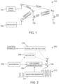
- FIG. 1 is a schematic illustration of a system arranged in accordance with examples described herein.
- the system 102 includes helper device 104, receiver 106, backscatter device 108, and backscatter device 110.
- the helper device 104 transmits a carrier signal.
- the backscatter device 108 and/or backscatter device 110 may backscatter the carrier signal into transmissions that may be compliant with a wireless communication protocol, such as Wi-Fi, ZigBee, and/or Bluetooth.
- the transmissions from the backscatter device 108 and/or backscatter device 110 may be received by the receiver 106.
- the receiver 106 may be any electronic device that is capable of receiving a wireless communication signal (e.g.
- backscatter devices may transmit to conventional electronic devices (e.g. wireless communication devices) using wireless communication protocols.
- Wi-Fi signals generally refer to wireless local area network communication signals, typically using the 2.4 GHz and/or 5 GHz ISM radio bands.
- the communication signals may be sent in accordance with the Institute of Electrical and Electronics Engineers' 802.11 standards, such as but not limited to, 802.11a, 802.11b, 802.11g, and/or 802.11n.
- the helper device 104 may be implemented using any electronic device capable of providing carrier signals (e.g. wireless communication device) described herein. Examples of helper devices include, but are not limited to, routers, mobile communications devices such as cell phones or tablets, computers, and/or laptops.
- the helper device 104 may generally have a wired power source, although in some examples the helper device 104 may be battery powered. Generally, the helper device 104 may have sufficient power to generate the carrier signal.
- a single helper device may provide a carrier signal to more than one backscatter device as described herein. Although a single helper device 104 is shown in Figure 1 , any number of helper devices may be used in some examples. In some examples, the helper device 104 may implement media access control protocols.
- the helper device 104 may transmit the carrier signal once the desired channel (e.g. a channel on which the carrier signal and/or backscattered signal will be transmitted) is determined to be free.
- the helper device 104 generally includes RF components, such as frequency synthesizer(s) and/or power amplifiers, which may then not be needed at the backscatter device 108 and/or backscatter device 110. In this manner the helper device 104 may provide the RF functions for any number of backscatter devices, such as backscatter device 108 and backscatter device 110.
- the carrier signal provided by the helper device 104 may be any of a variety of wireless signals which may be backscattered by the backscatter device 108 and/or backscatter device 110 to form a wireless communication signal arranged in accordance with a wireless communication protocol, such as Wi-Fi, ZigBee, Bluetooth, and/or SigFox.
- the carrier signal may be a continuous wave or a protocol-specific carrier signal (e.g. a Bluetooth, Wi-Fi, ZigBee, and/or SigFox signal).
- the carrier signal may be a spread spectrum signal.
- the carrier signal may be a frequency hopped signal.
- the carrier signal may be a continuous wave signal.
- one or more characteristics of the continuous wave signal may be selected in accordance with a particular wireless protocol and/or frequency and/or amplitude and/or phase that the receiver 106 is configured to receive.
- the carrier signal may be a single-frequency tone signal.
- the carrier signal may be a data-free signal.
- data decodable by the receiver may not be encoded in the carrier signal.
- the carrier signal may be implemented using a predetermined data signal.
- the carrier signal may not be encoded with data that is not predetermined and/or generated at the helper device 104.
- the carrier signal may be a non-payload signal.
- a data payload detectable by the receiver 106 may not be included in the carrier signal.
- the carrier signal may be a signal based on media access control sublayer processing performed by the helper device 104.
- the helper device may in some examples detect an unused portion of a spectrum and/or wireless communication channel. For example, the helper device may detect that a wireless communication channel, or portion thereof, is unused, and may selectively transmit a carrier signal on the wireless communication channel, or portion thereof, which is unused. In some examples, the carrier signal transmission may proceed only after the helper device determines that the wireless communication channel used by the carrier signal is unused. In some examples, additionally or instead, the helper device may detect that a wireless communication channel on which a backscatter signal is intended to be received, or portion thereof, is unused, and may selectively transmit a carrier signal when the receive channel is unused.
- carrier sense generally requires a Wi-Fi receiver that is ON before every transmission. Since traditional Wi-Fi receivers require power-consuming RF components such as ADCs, frequency synthesizers, and LNA, a requirement to conduct carrier sense at the backscatter device 108 and/or backscatter device 110 may reduce the overall power savings achieved from using backscatter techniques. Accordingly, in examples described herein, carrier sense may be performed by the helper device 104 and may not be performed by backscatter devices, such as the backscatter device 108 and/or backscatter device 110.
- the helper device 104 may perform carrier sense and signal a backscatter device, such as backscatter device 108 and/or backscatter device 110 when to transmit.
- the helper device 104 may also arbitrate the channel between multiple backscatter devices and address other link-layer issues including ACKs and retransmissions.
- the backscatter device 108 and backscatter device 110 may be implemented using and/or together with any devices having backscatter communication capability, such as, but not limited to, tags, mobile communication devices such as cell phones or tablets, computers, and/or laptops. Other devices may be implemented having backscatter communication capability, including but not limited to sensors, wearable devices such as watches, eyeglasses, contact lenses, and/or medical implants. It is anticipated that the backscatter devices may have a sufficiently small form factor and low power requirement as to be able to be incorporated in or attached to any object and provide communication functionality for the object and/or associated with the object. In this manner, backscatter devices may be placed ubiquitously in an environment, and facilitate Internet of Things (IoT) and/or other ubiquitous sensor functionality.
- IoT Internet of Things
- backscatter devices Although two backscatter devices are shown in Figure 1 , it is to be understood that any number of backscatter devices may be used, including one backscatter device. In other examples, 10, 20, 30, 40, 50, 60, 70, 80, 90, 100 or more backscatter devices may be present in the system 102.
- backscatter devices such as the backscatter device 108 and backscatter device 110 function to present varying impedance to a carrier signal such that, for example, the carrier signal is either reflected or absorbed by the backscatter device at any given time.
- a '1' may be indicated by reflection, and a '0' by absorption, or vice versa, and the carrier signal may be backscattered into a data-carrying signal.
- a data-carrying signal may be provided through backscatter using only the energy required to alter an impedance at a backscatter device's antenna. In this manner, the backscatter devices may transmit data-carrying signals at lower power than if the backscatter devices had themselves generated the carrier signals.
- Backscatter devices described herein such as backscatter device 108 and backscatter device 110 may generally be ultra-low power devices.
- backscatter devices described herein may eliminate or reduce the need for power hungry communication components (e.g. RF signal generators, mixers, analog-to-digital converters, etc., which may be present in the helper device 104). In this manner, backscatter devices described herein may consume microwatts of power to transmit data, which may improve the battery life of the component (e.g. sensor) utilizing the communication capability of the backscatter device.
- Backscatter devices may perform digital baseband operations, such as coding and/or modulation.
- the backscatter signal backscattered by the backscatter device 108 and/or backscatter device 110 may be a signal produced using subcarrier modulation performed by the backscatter device 108 and/or backscatter device 110.
- the frequency of the backscattered signal may be frequency-shifted from that of the carrier signal.
- data may be encoded in the backscattered signal using phase- and/or amplitude-shift keying.
- the backscattered signal may be based on phase-shift keying (e.g. QPSK and/or BPSK) and/or amplitude-shift keying subcarrier modulation performed by the backscatter device 108 and/or backscatter device 110.
- backscatter devices described herein including the backscatter device 108 and the backscatter device 110 may provide backscatter signals in accordance with wireless communication protocols that utilize phase- and/or amplitude-shift keying (e.g. Wi-Fi, ZigBee, SigFox).
- the backscattered signal may include DSSS and/or CCK spreading sequences, which may be added by the backscatter device 108 and/or backscatter device 110.
- the backscattered signal may include a payload, added to a signal generated by the helper device 104 after receipt of the carrier signal at the backscatter device 108 and/or backscatter device 110.
- the backscattered signal may include a packet, decodable at the receiver 106 based on a particular protocol or standard implemented by the receiver 106.
- the backscattered signal may include data detected at the backscatter device 108 and/or backscatter device 110 and added to a predetermined, frequency-specific carrier signal.
- Backscatter devices and/or helper devices described herein may each include multiple antennas. In this manner, antenna diversity may be leveraged and multiple-input-multiple-output (MIMO) techniques may be used.
- MIMO multiple-input-multiple-output
- the helper device 104 may distribute the carrier signal across multiple antennas based on the wireless channel, which may improve wireless signal propagation from the helper device 104 to the backscatter device 108 and/or 110 to the receiver 106.
- the receiver 106 may be implemented using any electronic device capable of receiving wireless communication signals (e.g. wireless communication device) formatted in the protocol provided by the backscatter devices backscatter device 108 and/or backscatter device 110, such as Wi-Fi and/or ZigBee.
- any electronic device e.g. wireless communication device
- the helper device 104, receiver 106, and backscatter device 108 and/or backscatter device 110 may be physically separate devices.
- the helper device 104 and receiver 106 may be integrated and/or may be the same device.
- an electronic device may include multiple antennas in some example.
- One or more antennas in some examples may provide the carrier signal (e.g. provide the helper device 104) while one or more antennas, different from those providing the carrier signal in some examples, may receive the signal transmitted by one or more backscatter devices (e.g. provide the receiver 106).
- the helper device and the receiver may be integrated into a single device.
- Cancellation circuitry may be provided in the integrated device to suppress (e.g. cancel) the carrier signal transmitted by the helper device at the receiver.
- the receiver 106 may receive transmission from the backscatter device 108 and/or backscatter device 110 in the presence of interference from the carrier signal transmitted by the helper device 104.
- specialized hardware may be used by the receiver 106 (e.g. a full-duplex radio) to cancel this interfering signal, however that may not be compatible with existing Wi-Fi devices.
- the helper device 104 may provide a carrier signal that is made up of frequencies (e.g. a single-frequency tone or a multi-frequency signal) outside a desired frequency channel for the transmissions of the backscatter device 108 and/or backscatter device 110. This may ensure and/or aid in the receiver 106 suppressing the out-of-band interference from the helper device 104.
- Wi-Fi receivers may increasingly be required to work even in the presence of interference in an adjacent band, such as interference that is 35 dB stronger. Accordingly, if the helper device 104 transmitted a carrier signal in the adjacent band, a traditional Wi-Fi receiver may be used to implement receiver 106 and would maintain function in the presence of the interfering signal. Further, as Wi-Fi and Bluetooth radios are being integrated onto single chipsets, Wi-Fi hardware is being designed to work in the presence of out-of-band Bluetooth interference.
- the helper device 104 may provide a Bluetooth carrier signal and a Wi-Fi chipset in the receiver 106 may operate appropriately to receive Wi-Fi transmissions from the backscatter device 108 and/or backscatter device 110 even in the presence of the interfering Bluetooth signal.
- helper device 104 some physical separation is provided between helper device 104 and receiver 106.
- excessive out-of-band interference may occur if the receiver 106 is too close to the helper device 104 such that the transmission of the carrier signal by the helper device 104 saturates and/or compresses the RF front end of the receiver 106, degrading Wi-Fi performance. This is generally referred to as the input 1 dB compression point, which may be around 0dBm for commercial Wi-Fi devices.
- the helper device 104 and receiver 106 described herein may change functionality from time to time in some examples.
- the helper device 104 at may function as described with reference to a helper device
- the helper device 104 may at times function as a receiver in some examples
- the receiver 106 may function as a helper device at times.
- a router e.g. a Wi-Fi router
- the router may be used having multiple modes of operation. In one mode of operation, the router may be used to implement the helper device 104, while in another mode, the router may be used to implement the receiver 106.
- the same device can time multiplex its functionality in some examples, such that the helper device 104 may be integrated and/or incorporated with the receiver 106.
- helper devices and/or receivers may be present in a system.
- a single device e.g. a router
- multiple (e.g. two) devices may be present in a system, each able to serve as either a helper device or a receiver.
- the device may function as a helper device (e.g. be configured to transmit a carrier signal) in one mode, and a receiver (e.g. be configured to receive a backscattered signal) in a second mode.
- the two devices may trade off serving as the helper device at any instance of time. For example, at one time Router 1 may function as the helper device whereas Router 2 may function as the receiver and at another time instant the roles may be reversed. Different time allocations may be used in some examples and a larger number of routers may be present in some examples.
- the helper devices and/or receivers may be positioned across an area to maximize and/or improve spatial coverage by the carrier signal and/or spatial coverage for receipt of backscattered signals.
- a helper device of the plurality of helper devices in a system may be selected to act as a helper device (in some examples, the selection may be specific to a specific backscatter device or group of backscatter devices) based on proximity of the candidate helper device to the backscatter device. In some examples, the selection may be made based on a candidate helper device of the plurality of helper devices having a better reception of a backscattered signal than another of the plurality of helper devices.
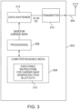
- FIG 2 is a schematic illustration of a backscatter device arranged in accordance with examples described herein.
- the backscatter device 200 may be used to implement, for example, the backscatter device 108 and/or backscatter device 110 of Figure 1 .
- the backscatter device 200 includes baseband 202, sub-carrier phase modulator 204, active RF 206, switch 208, and waveform generator 210.
- Backscatter devices generally operate by changing antenna impedance.
- the effect of changing the antenna impedance can be understood to cause the radar cross-section, e.g., the signal reflected by the antenna, also to change between the two different states.
- the power in the backscattered signal may be expressed as where ⁇ 1 * and ⁇ 2 * are the complex conjugates of the reflection coefficients corresponding to two impedance states.
- ⁇ 1 * and ⁇ 2 * are the complex conjugates of the reflection coefficients corresponding to two impedance states.
- the left had side of equation 2 may be set to 4, which can be achieved by modulating the reflection coefficients between +1 and -1.
- backscatter hardware may deviate from this ideal behavior and incurs losses, which are acceptable in practice; one example hardware implementation had a loss of around 1.1 dB.
- the antenna impedance may toggle between two impedance states.
- backscatter device 200 may generate transmissions (e.g. Wi-Fi transmissions) using this binary system.
- the switch 208 may be connected to ground.
- additional impedance states may be used.
- four impedances 212 are shown in Figure 2 which may be connected to the switch 208 and/or another switch 214 which may couple the impedances 212 to die transistor used to implement the switch 208. In this manner, any number of impedances may be presented to the antenna of the backscatter device. Examples described herein may utilize a variety of impedances (e.g. more than two) to provide single sideband backscatter.
- the backscatter device 200 may shift a frequency of a carrier signal by the backscatter device 200.
- the frequency may be shifted from a single-frequency tone provided outside a desired Wi-Fi transmission channel to a frequency within the desired Wi-Fi transmission channel (e.g. the center frequency of the desired Wi-Fi transmission channel).
- the frequency-shifted signal may be used to provide wireless communication signal (e.g. Wi-Fi signals).
- the switch 208 may be operated at a frequency ⁇ f equal to an amount of desired frequency shift.
- Digital encoding may be performed using digital logic and phase changes may be implemented in some examples by modifying a phase of a square wave (e.g. used to approximate a sine wave). In this manner, the digital backscatter device 200 may synthesize wireless communication signals (e.g. Wi-Fi signals) while operating in the digital domain at baseband.
- the backscatter device 200 may backscatter a single-frequency tone signal, e.g. provided by the helper device 104 of Figure 1 .
- the single-frequency tone signal may be written as sin2 ⁇ (f wifi - ⁇ f)t, where f wifi is the desired frequency of Wi-Fi transmission by the backscatter device, and ⁇ f is the frequency of a waveform utilized by the backscatter device.
- the backscatter device 200 may utilize a square wave at a frequency ⁇ f (e.g. provided by the waveform generator 210) to shift the tone to f wifi .
- the square wave provided by the waveform generator 210 can be approximated as 4 ⁇ sin 2 ⁇ ⁇ ft
- the backscatter signal can be approximated as sin2 ⁇ ( f wifi - ⁇ f)tsin2 ⁇ ft. In this manner, backscatter has created two tones, one at f wifi and one at f wifi - 2 ⁇ f from the initial single-tone signal.
- backscatter devices described herein may provide backscatter signals having a frequency that is shifted from the frequency of a carrier signal by a difference frequency.
- the difference frequency may be a frequency of (or included in) a waveform provided to the subcarrier modulation circuitry.
- backscatter devices may provide backscatter signals shifted from the frequency of a carrier signal by a difference frequency and may avoid generating both sidebands of the backscatter signal (e.g. backscatter devices may provide a backscatter signal at a carrier signal frequency + the difference frequency while avoiding providing a backscatter signal at the carrier signal frequency - the difference frequency, e.g. the backscatter signal may be provided in only a single sideband.)
- both the advertising channels 37 and 39 are at either end of the ISM band.
- creating any frequency shifts to the corresponding Bluetooth signal may create a mirror copy outside the ISM band.
- the third advertising channel, 39 overlaps with Wi-Fi channel 6 and is close to Wi-Fi channel 1 and hence may create strong interference to the weak backscattered Wi-Fi signals.
- generating packets on Wi-Fi channel 11 using advertising channel 39 may again create a mirror copy that lies outside the ISM band.
- existing sideband modulation techniques may not be advantageous for achieving interscatter on any of the Wi-Fi channels.
- Backscatter devices may produce a frequency shift on only one side of the single tone carrier (e.g. Bluetooth) transmission.
- the approach may be explained by considering radio operation.
- a radio may use oscillators at a radio frequency, e.g. 2.4 GHz, to generate the orthogonal signals, cos2 ⁇ ft and sin2 ⁇ ft. These are multiplied with digital in-phase, I(t) and quadrature phase components, Q(t) to create I(t)cos2 ⁇ ft + jQ(t)sin2 ⁇ ft.
- radios can easily create the desired shifted signal, e j2 ⁇ (f+ ⁇ f )t , without any mirror copies. Examples described herein, however, may not advantageously utilize oscillators running at a radio frequency, e.g. 2.4 GHz, since they would consume significant power.
- the above operations may be imitated using complex impedances on the backscatter device without high frequency (e.g. 2.4 GHz) oscillators.
- the complex signal, e j2 ⁇ ft may be provided (e.g. by waveform generator 210).
- the incoming carrier signal e.g. single-tone Bluetooth transmission
- cos2 ⁇ ft results in,
- the first term is the desired shifted signal while the second term has a negative frequency and does not occur in practice.
- the above operation creates the desired shift without a mirror copy.
- examples of backscatter devices described herein may provide the complex signal e j2 ⁇ ft using backscatter, thereby achieving single-sideband backscatter modulation.
- the sin/cos terms may be generated using square waves.
- Complex impedances at the switch e.g. switch 208 may be used to generate the complex values.
- Equation 5 the sin/cos terms in Equation 5 are generated using a square wave going between the two values, +1 to -1, at a frequency of ⁇ f.
- the first harmonic is the desired sine term while the third and fifth harmonic have a power of 1/ n 2 which are 9.5 dB and 14 dB, respectively, lower than the first. Since all 802.11b bit rates may operate at SNRs lower than 14dB, such an approximation is sufficient for examples described herein.
- backscatter devices described herein time shift a square wave by a quarter of the time period. This square wave may be generated by clocking the switch (e.g. switch 208) and the digital operations of the backscatter device at multiples of the desired difference frequency ⁇ f.
- Eq. 5 can take one of four values: 1+j, 1-j, -1+j, and -1-j. These complex values may be created by changing the impedance of the backscatter hardware (e.g. utilizing the impedances 212). Generally, RF signals are reflected when they cross two materials that have different impedances. Since the impedance of an antenna is different from the medium around it, a fraction of the incident RF signals get reflected off the antenna.
- Za and Zc are the impedance of the antenna and the backscatter circuit (e.g. the switch 208 and impedances 212) respectively.
- the impedance of the backscatter circuit may be set to either Za or 0 corresponding to no reflections or reflections of the incoming signal.
- the impedance of the backscatter circuit can be set to complex values by changing the inductance of the circuit. For example, at the frequency f , the impedance of the backscatter circuit may be written as j2 ⁇ fL where the inductance is L. Thus, by changing the inductance, complex values may be provided for the fraction in equation 7 above.
- the impedances 212 may be set as ⁇ j 2 + j Z a , j 2 ⁇ j Z a , 2 ⁇ j j Z a and 2 + j ⁇ j Z a respectively.
- Z a the antenna impedance
- Switching between the four impedance states may allow the backscatter device to provide the complex signal e j2 ⁇ ft and achieve single sideband operation.
- the switch 214 or other switching elements may switch between a number of impedance elements, such as the four impedance elements shown in impedances 212.
- the switch 214 or other switching elements may be controlled by the baseband 202, sub-carrier phase modulator 204, and/or waveform generator 210 of Figure 2 in some examples.
- the waveform generator 210 provides a square wave and a square wave shifted by a quarter period. These may represent the sine and cosine terms of Equation 5.
- Impedances 212 may include four impedance elements sufficient to cause the impedance of the backscatter circuit (e.g. backscatter device) to be- ⁇ j 2 + j Z a , j 2 ⁇ j Z a , 2 ⁇ j j Z a and 2 + j ⁇ j Z a at various times. Switching between these values allows the backscatter device to backscatter a signal into a third frequency without also generating the mirror image sideband at another frequency.
- the backscatter circuit e.g. backscatter device
- the backscatter signal may be provided at a frequency equal to a carrier frequency plus a difference frequency without also providing a backscatter signal at a frequency equal to the carrier frequency minus a difference frequency.
- the backscatter signal may be provided at a frequency equal to a carrier frequency minus a difference frequency without also providing a backscatter signal at a frequency equal to the carrier frequency plus the difference frequency.
- Data may be transmitted in backscatter signals in a number of ways.
- reflection and/or absorption of the carrier signal itself may be utilized to encode data.
- a carrier wave may be implemented using a signal having packets or other data (e.g. a Wi-Fi signal).
- the backscatter device may transmit and/or reflect packets of the carrier signal to indicate a '1' or '0' (or vice-versa).
- phase- and/or amplitude-shift keying may be performed by the backscatter device to encode data in the backscatter signals. For example, following creation of a tone centered at the Wi-Fi channel (f wifi ), 802.11b transmissions using backscatter may be generated.
- the backscatter device 200 may generate signals in accordance with a phase-shift keying protocol (e.g. QPSK, BPSK, DBPSK and/or DQPSK) using a square wave created at a frequency ⁇ f, which may be understood by noting that DBPSK and DQPSK use a sine wave with four distinct phases: 0, ⁇ /2 , ⁇ , and 3 ⁇ /2. Since the square wave provided by switch 208 can be approximated as a sine wave, the four phases may be provided by changing the timing of the square wave provided by the waveform generator 210.
- a phase-shift keying protocol e.g. QPSK, BPSK, DBPSK and/or DQPSK
- backscatter devices such as backscatter device 200 may fully operate in the digital domain while run at a baseband frequency of a few tens of MHz and synthesize 802.11b transmissions using backscatter.
- the baseband 202 may provide data for communication to the sub-carrier phase modulator 204, which may also be referred to as a sub-carrier modulator. It is to be understood that even when referred to as a sub-carrier phase modulator, phase modulation may not be performed in all examples.
- the waveform generator 210 may provide a waveform to the sub-carrier phase modulator 204. A frequency of the waveform may be selected as a difference between a frequency of the carrier signal and a desired frequency of the backscatter signal (e.g. frequency at which a receiver may receive the backscatter signal).
- the data may be provided in the backscatter signal in several ways.
- the sub-carrier phase modulator 204 may control the switch 208 to reflect and/or absorb portions of the carrier signal (e.g. packets) in accordance with the data. For example, packets of the carrier signal may be reflected to indicate a '0' and absorbed to indicate a '1', or vice versa. In some examples, the sub-carrier phase modulator 204 may alter a phase, amplitude, or both of the waveform provided by the waveform generator 210 to provide an output signal.
- portions of the carrier signal e.g. packets
- packets of the carrier signal may be reflected to indicate a '0' and absorbed to indicate a '1', or vice versa.
- the sub-carrier phase modulator 204 may alter a phase, amplitude, or both of the waveform provided by the waveform generator 210 to provide an output signal.
- the output signal may be used to control a switch 208 to backscatter a carrier signal into a data-carrying signal formatted in accordance with a wireless communication protocol utilizing phase-shift keying, a wireless communication protocol using amplitude-shift keying, or combinations thereof.
- backscatter devices provide backscatter signals which are Wi-Fi signals (e.g. IEEE 802.11b signals).
- the backscatter devices may provide a backscattered signal which is formatted in accordance with a Wi-Fi protocol (e.g. IEEE 802. 1 1b). In this manner, the backscattered signal may be received and decoded by any Wi-Fi capable device in some examples.
- a Wi-Fi protocol e.g. IEEE 802. 1 1b
- 802.1 1b signals are described by way of example, it is to be understood that in other examples, the backscatter devices may provide Bluetooth, ZigBee, or other wireless communication signals.
- a Wi-Fi signal may be written as (I wifi (t) + Q wifi (t))e j2 ⁇ f wifi t where I wifi (t) and Q wifi (t) correspond with the in-phase and quadrature-phase components of the baseband Wi-Fi signal, respectively.
- the Wi-Fi signal may be written as
- backscatter devices described herein may create (I wifi (t) + Q wifi (t))e j2 ⁇ ft using backscatter. Examples of generation of e j2 ⁇ ft are described herein (e.g. using switching between multiple impedances of the backscatter device). That signal may be multiplied by the in-phase and quadrature-phase components of 802.11b to generate Wi-Fi signals.
- IEEE 802.11b signals utilize DSSS/CCK coding that creates coded bits which are then modulated using either DBPSK or DQPSK.
- backscatter devices which transmit DBPSK and/or DQPSK may transmit Wi-Fi backscatter signals (e.g. IEEE 802.11b signals).
- the one and zero bits may be represented as +1 and -1, which may generally be considered setting Q wifi (t) to zero and I wifi (t) to either +1 or -1. Since e j2 ⁇ ft takes the values in the set ⁇ 1+j, 1-j, -1+j, -1-j ⁇ , multiplying it with +1 or -1 resulting in values within the same set, which we can be generated by backscatter devices described herein utilizing multiple impedance values for the backscatter device. Thus, DBPSK modulation may be provided by backscatter devices described herein, which may therefore achieve 1 and 5.5 Mbps IEEE 802.11b transmissions.
- both I wifi (t) and Q wifi (t) may be set to either +1 or -1.
- the baseband Wi-Fi signal can take one of the following values: ⁇ 1+j, 1-j, -1+j, -1-j ⁇ . Multiplying this with e j2 ⁇ ft which takes one of the following values ⁇ 1+j, 1-j, -1+j, -1-j ⁇ , results in one of these four normalized values: ⁇ 1,-1,j,-j ⁇ .
- ⁇ 1,-1,j,-j ⁇ and ⁇ 1+j, 1-j,-1+j, -1-j ⁇ are constellation points that are shifted by ⁇ /4. Since 802.11b uses differential QPSK, the constant phase shift of ⁇ /4 may be ignored and instead the four complex impedance values provided by backscatter devices described herein may be used. Wi-Fi receivers may ignore the constant phase shift since the bits are encoded using differential phase modulation. In this manner, DQPSK modulation may be provided by example backscatter devices described herein, which may therefore achieve 2 and 11 Mbps 802. 11b transmissions.
- Some example backscatter devices may additionally include active RF 206 components such that in one mode, the backscatter device 200 may backscatter signals and have low power (e.g. backscatter) operation, while in another mode the backscatter device 200 may utilize active RF 206 to transmit wireless communication signals conventionally (e.g. generating the device's own carrier signal).
- the backscatter components and active RF 206 may utilize a same antenna, as shown in Figure 2 , and the antenna connection may be switched between the active RF 206 and sub-carrier phase modulator 204 in some examples by control circuitry (not shown in Figure 2 ). In other examples, the active RF 206 and sub-carrier phase modulator 204 may utilize different antennas.
- the antenna may be connected to a switch which selects between the active RF 206 radio and the sub-carrier phase modulator 204. The selection may be made, for example, on a basis of proximity to a helper device. In some examples, when the backscatter device is in the range of a helper device it may couple the sub-carrier phase modulator 204 to the antenna to perform low power transmissions (e.g. Wi-Fi transmissions). However, when the backscatter device is outside the range of the helper device, the antenna may be coupled to active RF 206.
- Baseband 202 may be implemented using typical baseband circuitry for the wireless communication protocol of interest, e.g. Wi-Fi baseband circuitry and/or ZigBee baseband circuitry. Generally, the baseband 202 includes digital circuitry components which may be relatively low power. The baseband 202 may provide encoding in accordance with the wireless communication protocol of interest (e.g. DSSS and CCK encoding for 802.11b transmissions). The data provided by the baseband 202 may originate from one or more sensors which may be coupled to and/or integrated with the backscatter device 200 in some examples. Any number of sensors may be used, including but not limited to, temperature sensors, vibration sensors, humidity sensors, glucose sensors, pH sensors, blood oxygenation sensors, GPS sensors, optical sensors, cameras, and/or microphones. In this manner, sensor data may be provided that may be transmitted by the backscatter device 200.
- sensors including but not limited to, temperature sensors, vibration sensors, humidity sensors, glucose sensors, pH sensors, blood oxygenation sensors, GPS sensors, optical sensors, cameras, and/or
- the backscatter device 200 may implement WPA/WPA2 and ensure that its Wi-Fi transmissions comply with the Wi-Fi security specifications. Since these are digital operations, the baseband 202 may implement them on the backscatter device 200 using baseband processing.
- the backscatter device 200 may include a power source, such as a battery and/or energy harvesting system.
- the battery may be implemented using a lithium ion battery.
- energy harvesting components may be provided to power the backscatter device 200, including, but not limited to, components for harvesting solar energy, thermal energy, vibrational energy, or combinations thereof.
- the power source may power the baseband 202, sub-carrier phase modulator 204, and waveform generator 210.
- the active RF 206 may be used when a larger power source than the power source used to power those backscatter components is available (e.g. a wired power source).
- the sub-carrier phase modulator 204 may be implemented using circuitry that may adjust a phase, amplitude, or both of a waveform.
- an FPGA may be used to implement sub-carrier phase modulator 204.
- the sub-carrier phase modulator 204 is connected to the baseband 202 and may receive data from the baseband 202.
- the sub-carrier phase modulator 204 may be further connected to the waveform generator 210 and may receive a waveform provided by the waveform generator 210.
- the sub-carrier phase modulator 204 may alter a phase, amplitude, or both, of the waveform in accordance with the data from the baseband 202 to provide an output signal.
- the sub-carrier phase modulator 204 may be coupled to the switch 208 and may provide the output signal to the switch 208.
- ZigBee uses offset QPSK and direct sequence spread spectrum (DSSS) in the 2.4 GHz ISM band.
- Wi-Fi is generally implemented using BPSK/QPSK modulation with DSSS/CCK spreading sequences.
- the sub-carrier phase modulator 204 may alter a phase of a square wave provided by waveform generator 210 by changing the timing of the wave.
- the sub-carrier phase modulator 204 may utilize QPSK modulation in other examples to synthesize a Wi-Fi and/or ZigBee packet.
- a payload of the packet may include the spreading sequence for the carrier signal.
- the spreading sequence may be provided by the baseband 202 and/or may be stored in a memory on the backscatter device 200.
- phase shift keying may be implemented, for example by replacing the switch 208 with a multiplexer or switching network and switching the antenna impedance between four impedance states (e.g. which may all be placed 90° apart in phase on a circle) to implement phase shift keying.
- Amplitude shift keying may be implemented in an analogous manner.
- Switch 208 may be implemented using generally any circuitry for altering impedance presented to an antenna, such as a transistor.
- the switch 208 is coupled between the sub-carrier phase modulator 204 and an antenna of the backscatter device 200.
- the switch 208 is implemented using a transistor. Any of a variety of antenna designs may be used.
- the antenna may be operational in the frequency of the carrier signal and the frequency of the backscatter signal.
- a high output signal provided by the sub-carrier phase modulator 204 to the gate of the switch 208 accordingly may turn the transistor on, presenting a low impedance to the antenna.
- the switch 208 may generally run at a baseband frequency - e.g. a much lower frequency than a frequency of a carrier signal provided to the backscatter device 200.
- the switch 208 may be operated at a frequency of 50 MHz or lower, although other frequencies may also be used in other examples.
- Switch 214 may be implemented using generally any circuitry for altering impedance presented to an antenna, such as a transistor.
- the switch 214 may be integrated with the switch 208.
- the switch 214 may allow for different impedances to be coupled to the antenna of the backscatter device, such as the impedance elements 212.
- the impedance elements 212 may be provided in parallel and the switch 214 may couple a selected one of the impedance elements 212 to the antenna.
- the impedance elements 212 may be provided in parallel, and one or more switches may be provided to add and/or remove impedance elements from being coupled to the antenna.
- the impedance elements 212 may generally be implemented using any components having an impedance including, but not limited to, one or more resistors or inductors.
- Waveform generator 210 may provide a waveform to the sub-carrier phase modulator 204. Any periodic waveform may generally be used including, but not limited to, a square wave, sine wave, cosine wave, triangle wave, sawtooth wave, analog signal, multi-level signal, or combinations thereof.
- the waveform generator 210 may be implemented using, hardware, software, or combinations thereof.
- the waveform generator 210 may be implemented using an oscillator.
- the phase of a waveform provided by the waveform generator 210 having an oscillator may be altered, for example, by changing a phase of a clock signal provided to the oscillator.
- the waveform generator 210 may be implemented using an FPGA, DSP, and/or microprocessor and executable instructions to provide the desired waveform at the desired frequency.
- the carrier signal may have a particular frequency - e.g. a single tone, a frequency used in Bluetooth, Wi-Fi, ZigBee, and/or other wireless communication protocol. It may be desirable for the backscatter device 200 to transmit a backscattered signal at a particular frequency (e.g. at a frequency used in Bluetooth, Wi-Fi, ZigBee, or other wireless communication protocol). It may be desirable for the backscattered signal to occur at a different frequency than the carrier signal, for example to avoid or reduce interference between the carrier signal and the backscattered signal.
- a particular frequency e.g. a single tone, a frequency used in Bluetooth, Wi-Fi, ZigBee, and/or other wireless communication protocol. It may be desirable for the backscattered signal to transmit a backscattered signal at a particular frequency (e.g. at a frequency used in Bluetooth, Wi-Fi, ZigBee, or other wireless communication protocol). It may be desirable for the backscattered signal to occur at a different frequency than the
- the waveform generator 210 may provide a waveform at a frequency which may be selected to be a frequency equal to a difference between a frequency of the carrier signal and a desired frequency for transmission of a backscattered signal.
- the sub-carrier phase modulator 204 may control the switch 208 at the frequency of the waveform provided by the waveform generator 210 which may effectively mix the frequency of the carrier signal with the frequency of the waveform, resulting in a backscattered signal at a frequency of the carrier signal +/- the frequency of the waveform.
- the waveform generator 210 provides two square waves - one shifted one quarter phase relative to the other and the backscatter device may switch between multiple (e.g.
- a backscattered signal at a desired frequency may be achieved by providing a waveform to the sub-carrier phase modulator 204 having a frequency equal to a difference between the frequency of the carrier signal and the desired frequency of backscatter transmission.
- the carrier signal may be a frequency hopped signal.
- the waveform generator 210 may provide a waveform having a frequency that hops in accordance with the hopping of the frequency hopping signal used to implement the carrier signal such that the frequency hopping carrier signal may be backscattered by the backscatter device 200.
- the carrier signal may be a frequency hopped signal which has a sequence of frequencies over time.
- the receive frequency may generally be fixed. Accordingly, the waveform generator 210 may provide a waveform having a sequence of frequencies such that the data is transmitted at the constant receive frequency over time, despite the hopping frequency of the carrier signal.
- the sequence of frequencies of the frequency-hopped carrier signal may be received by the backscatter device over a downlink from the helper device used to transmit the carrier signal.
- the sequence of frequencies may be known (e.g. a pseudorandom sequence).
- the backscatter device may include a memory that may store the sequence of frequencies of the frequency-hopped carrier signal and/or the sequence of frequencies used for the waveform, or indications thereof.
- backscatter devices described herein may include frequency determination circuitry coupled to an antenna for sensing the carrier signal (e.g. the antenna used to backscatter may be used).
- the frequency determination circuitry may sense the frequency of the carrier signal and compute a difference between the frequency of the carrier signal and the desired frequency of backscatter signal and provide an indication of the difference (e.g. to be used as the waveform frequency) to the waveform generator such that the waveform generator may provide the waveform at the indicated difference frequency.
- the carrier signal may be a spread spectrum signal, such as a direct spread spectrum (DSS) signal.
- DSS direct spread spectrum
- direct spread spectrum refers to techniques where energy may be spread across multiple frequencies (e.g. a frequency band) by coding data in a particular manner using a code or coding sequence.
- Coding sequences may be pseudorandom sequences, and examples include m-sequences, barker codes, gold codes, and Hadamard Walsh codes.
- a time at which backscattering begins may need to be synchronized to the spread spectrum carrier signal.
- data may be provided in a backscattered signal in some examples by altering the carrier signal.
- the backscatter device may begin backscattering when a particular portion of the carrier signal is presented to the backscatter device (e.g. the backscatter device may synchronize backscattering of data with data in the carrier signal).
- the sub-carrier phase modulator of a backscatter device may begin backscatter at a time based on features of the carrier signal.
- Features may include data present in the carrier signal at a particular time and/or a location within an overall spreading sequence at a particular time.
- the sub-carrier phase modulator may begin backscatter responsive to a synchronization signal from another device.
- a master synchronization may be provided where a device (e.g. the helper device) may provide a signal to the backscatter device to indicate a time to begin backscatter relative to the spread spectrum carrier signal.
- Data may be provided in the backscatter signal in several ways.
- data may be provided in the backscatter signal by reflecting and/or absorbing portions (e.g. packets) of the carrier signal in accordance with the data to be transmitted.
- a receiver may decode the presence of a packet in the backscatter signal as a '1' (or a '0' in some examples) and the absence of a packet in the backscatter signal as a '0' (or a '1' in some examples).
- the backscatter device may encode data in the packet sequence number transmitted by the helper device.
- data may be provided in the backscatter signal by altering a phase, amplitude, or combinations thereof, of the waveform provided to the sub-carrier modulation circuitry in accordance with the data to perform phase-shift keying and/or amplitude-shift keying.
- the backscatter device 200 may create wireless communication transmissions (e.g. which may be arranged in accordance with a standard wireless communication protocol, such as but not limited to Wi-Fi 802.11a, 802.11b, 802.11g, 802.11n, ZigBee, and/or Bluetooth). Since the backscatter device 200 has no (or fewer) analog components, it may generally consume less silicon area and be smaller and cheaper than existing transmission devices, such as Wi-Fi chipsets. Further, its power consumption may be significantly lower as it may only have a need to perform digital baseband operations.
- the backscatter device 200 may further include a receiver for receiving signaling message from, e.g. the helper device 104.
- the helper device 104 may provide signaling packets which may, for example, be created using amplitude modulation such as ON/OFF keying.
- the backscatter device 200 may include a passive energy detector (e.g. envelope detector 216) with analog components and a comparator to distinguish between the presence and absence of energy. In this manner, signaling packets may be received while consuming low power, 18 mW in some examples.
- the carrier signal may be a single tone signal.
- a helper device such as the helper device 104 of Figure 1 may be implemented using a Bluetooth capable electronic device, and the carrier signal may be provided from a Bluetooth signal. In this manner, examples described herein may transform transmissions from Bluetooth devices into Wi-Fi signals.
- a single-tone carrier signal may be provided using one or more Bluetooth device.
- a Wi-Fi signal (e.g. an 802.11b signal) may then be generated by a backscatter device from the single tone Bluetooth transmission.
- Bluetooth devices generally use advertisement channels to broadcast information about their presence and to initiate connections. Once the connection is established with a nearby Bluetooth device, they communicate by hopping across the 36 data channels spread across the 2.4 GHz ISM band.
- the three advertisement channels are labeled as channels 37, 38 and 39, Since transmissions on data channels require establishing a connection with another device, Bluetooth advertisement channels may advantageously be used by helper devices described herein where we they broadcast packets.
- Bluetooth generally uses Gaussian Frequency Shift Keying (GFSK) modulation with a bandwidth of 1 MHz. Specifically, a '1' ('0') bit is represented by a positive (negative) frequency shift of around 250 kHz from the center frequency. The resulting FSK signal is then passed through a Gaussian filter to achieve good spectral properties.
- GFSK Gaussian Frequency Shift Keying
- Wi-Fi IEEE 802.11b generally operates on three nonoverlapping channels, each 22 MHz wide. To create 1 and 2 Mbps transmissions, 802.11b first XORs each data bit with a Barker sequence to create a sequence of eleven coded bits for each incoming data bit, which it then modulates using DBPSK and DQPSK. To create 5.5 and 11 Mbps transmissions, 802.11b uses CCK where each block of four incoming bits is mapped to 8-bit code words, which are then transmitted using DBPSK and DQPSK.
- Examples described herein may transform Bluetooth devices into a single tone transmitter, e.g., cause a Bluetooth device to transmit a signal with constant amplitude and frequency. Accomplishing this can generally be considered to leverage two insights about GFSK modulation used in Bluetooth.
- Bluetooth uses two frequencies to encode the zero and one data bits. Thus, if a device transmits a stream of constant ones or zeros, a single frequency tone may be created.
- Second, passing a single tone through the Gaussian filter used by a Bluetooth device does not generally change its spectral properties since the filter only smooths out abrupt changes to the frequency. Thus, a Bluetooth device is controlled to transmit a continuous stream of zeros or ones, it may effectively produce a single tone.
- a Bluetooth device e.g. an electronic device having a Bluetooth chipset or otherwise capable of transmitting a Bluetooth signal
- Those challenges may include data whitening and the link-layer packet structure.
- Bluetooth devices generally utilize data whitening, however, to avoid such sequences so as to enable accurate timing recovery on a Bluetooth receiver. Accordingly, examples of helper devices described herein may provide data for Bluetooth device transmission that cause the data whitener to produce a string of 1s and/or 0s.
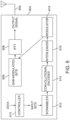
- Figure 3 is a schematic illustration of an example helper device that may utilize Bluetooth signals as a carrier wave, arranged in accordance with examples described herein.
- Figure 3 depicts helper device 302.
- the helper device 302 includes antenna 304, processor(s) 306, computer readable media 308, executable instructions for carrier wave generation from Bluetooth 310, data whitener 312, and transmitter 314.
- the data whitener 312 is in communication with the transmitter 314 which is in communication with antenna 304.
- the processor(s) 306 is in communication with the computer readable media 308 which may be encoded with the executable instructions for carrier wave generation from Bluetooth 310.
- the helper device 302 may be implemented using any Bluetooth capable electronic device including, but not limited to, a server computer, client computer, other computer, laptop, desktop, tablet, cell phone, watch, other wearable device, appliance, automobile, aircraft, or combinations thereof.
- the processor(s) 306 may be implemented using any hardware that may provide the described processing functionality, including one or more processors, or logic or other circuitry (e.g. a Bluetooth chipset).
- the computer readable media 308 may be implemented using generally any electronic storage, including, but not limited to, RAM, ROM, flash, disk drive(s), or other storage.
- the computer readable media 308 (which may include one or more instances of computer readable media) may be encoded with the executable instructions for carrier wave generation from Bluetooth 310.
- the executable instructions for carrier wave generation from Bluetooth 310 may be encoded on the computer readable media 308.
- the helper device 302 may have an application installed that may include the executable instructions for carrier wave generation from Bluetooth 310.
- the data whitener 312 may be implemented using any typical data whitening circuitry that may be used by Bluetooth devices.
- an example data whitener is shown in Figure 4.
- Figure 4 is a schematic illustration of an example data whitener commonly used in Bluetooth devices.
- Bluetooth devices generally use the 7-bit linear feedback shift register circuit in Figure 4 with the polynomial x 7 + x 4 + 1.
- the circuit of Figure 4 outputs a sequence of bits (e.g. .output from the register numbered 6 in Figure 4 ) that are used to whiten the incoming data by XORing the data bits with the bits output by the circuit.
- the combiner 402 may perform an XOR operation.
- a bit sequence is provided out of the 7-bit linear feedback shift register and is XOR d with incoming data to provided whitened data.
- the whitening sequence output by the 7-bit linear feedback shift register may also be known.
- the shift registers may be initialized with the Bluetooth channel number.
- Bluetooth generally specifies to initialize the zeroth register to a one and the rest of the six registers to the binary representation of the Bluetooth channel number.
- the zeroth register in Fig. 4 may be set to 1 and the rest are set to the binary representation of 37.
- the initialized state of the registers may be known and the whitening sequence (e.g. the series of bits output from the 7-bit linear feedback shift register circuit) may be known.
- the data whitener 312 may be implemented using the data whitener 400 of Figure 4 in some examples.
- the executable instructions 310 may include instructions for reversing the whitening process of the data whitener 312.
- the executable instructions 310 may include instructions for providing data bits to the data whitener which are the same bits in the whitening sequence or its bit complement. In this manner, combining that data with the data whitening sequence may result in a sequence of zeros or ones, respectively, to be output from the data whitener and transmitted by the Bluetooth device.
- the executable instructions 310 may include instructions for determining the whitening sequence (e.g. calculating a whitening sequence that may be output by the data whitener based on an initialization).
- the transmitter 314 may transmit data in accordance with a Bluetooth standard utilizing the antenna 304.
- the transmitted carrier wave will generally be a single tone carrier wave.
- examples described herein may be used to provide a long (e.g. as long as possible given Bluetooth packet constraints) string of exclusively 0s or exclusively 1s to the transmitter 314.
- the string of 1s or 0s may be a length of an entire Bluetooth packet payload, a length of 7/8 the Bluetooth packet payload in some examples, a length of 2/3 the Bluetooth packet payload in some examples, a length of 1 ⁇ 2 the Bluetooth packet payload in some examples. Other lengths may be used in other examples.
- FIG. 5 is a schematic illustration of an example Bluetooth packet structure.
- the Bluetooth packet 500 may include preamble, access address, length, data, and CRC bits.
- the data bits may include an advertiser address and a payload. It is the payload (or portions of the payload) that may be set to a string of 1s or 0s for single tone carrier wave generation described herein.
- the preamble and access address fields may not be arbitrarily modified.
- the preamble may be fixed to an alternating sequence of zeros and ones and the access address may be set to 0X8E89BED6 for advertising packets. This is followed length field and an advertiser address field.
- the packet has the data payload and a 3-byte CRC. Of these fields, only the payload may generally be set to arbitrary values (e.g. the 0s and 1s described herein).
- the Bluetooth preamble, access address and the header may be used to enable Bluetooth packet detection at a backscatter device using an envelope detection circuit.
- the beginning of the payload may be estimated by the backscatter device and the backscatter device may begin backscattering at the estimated time of the payload start to generate, for example, Wi-Fi packets as described herein.
- the Wi-Fi transmission may be completed before the start of the Bluetooth CRC field. Since the CRC may be transmitted on a different channel than the generated Wi-Fi packet, it generally does not affect the backscattered signal.
- examples of backscatter devices described herein may include an envelope detector, such as the envelope detector 216.
- the envelope detector may be a very (e.g. ultra) low power envelope detector suitable for low-power backscatter device operation.
- the envelope detector 216 may be coupled to the antenna of the backscatter device and may detect incident energy, which may be, e.g. the start of an incident packet of a carrier wave.
- the envelope detector 216 may be designed (e.g. calibrated) to provide a signal responsive to receipt of a transmission from a device within a particular radius (e.g.
- the envelope detector 216 may provide a signal responsive to detection of incident energy.
- the output of the envelope detector 216 may be used to provide one or more control signals to components of the backscatter device 200 such as the baseband 202, sub-carrier phase modulator 204, waveform generator 210, or combinations thereof.
- Components of the backscatter device may accordingly be controlled to initiate backscattering responsive to detection of a threshold amount of incident energy (e.g. an amount indicative of receipt of a carrier wave) by the envelope detector 216.
- the envelope detector may be responsive to incident energy and may not provide an accurate indication of a beginning of a packet, e.g. a Bluetooth packet, since the preamble may not be decoded. Accordingly, synchronization operations may not be performed by the backscatter device 200, which may result in an error in accurately estimating a start of the packet payload. Accordingly, a guard interval may be used in some examples.
- components such as the baseband 202, sub-carrier phase modulator 204, waveform generator 210, or combinations thereof, may begin backscatter operations a guard interval after receipt of a control signal from the envelope detector 216.
- control signal may be provided by the envelope detector 216 a guard interval after the threshold amount of incident energy was detected.
- the guard interval may be 3 ⁇ s in some examples, 4 ⁇ s in some examples, 5 ⁇ s in some examples, 6 ⁇ s in some examples. Other guard intervals may be used in other examples.
- the payload portion of a Bluetooth packet may be a series of all 0s or all 1s in some examples.
- Backscatter devices such as the backscatter device 200 of Figure 2 , may detect a start of the Bluetooth packet 500 shown in Figure 5 (e.g. using envelope detector 216 of Figure 2 ). Responsive to detecting the Bluetooth packet, a guard interval may elapse prior to the backscatter device beginning backscatter operations. The guard interval may be selected to ensure or aid in causing the backscatter device to backscatter the payload portion of the Bluetooth packet 500 which, as described herein may be a single tone signal.
- the backscatter device may limit an amount of data transmitted such that the backscattered signal is completed prior to start of the CRC portion of the Bluetooth packet 500.
- a Bluetooth advertising packet can have a payload up to 31 bytes or 248 ⁇ s. Since Wi-Fi packets at different bit rates may occupy the channel for different times, this translates to different packet sizes. At 2, 5.5 and 11 Mbps the Wi-Fi payload can be 38, 104, and 209 bytes within a single Bluetooth advertising packet. Given its size, however, a 1 Mbps Wi-Fi packet may not fit in (e.g. may not be produced using backscatter of) a single Bluetooth advertising packet. Note that Bluetooth data transmissions are generally around 2 ms which could in principle increase the packet sizes across all the 802.11b bit rate as well as enable 1 Mbps transmission. Examples using Bluetooth advertising packets are described herein, however, other Bluetooth packets may be used in other examples.
- Bluetooth does not generally perform carrier sense before transmitting. Further, the backscattered signal (e.g. Wi-Fi packet) may be at a different frequency that could be occupied, resulting in a collision. Since Bluetooth advertisements are small and sent once every 20 ms, such collisions may have a negligible impact on Wi-Fi which operate at a much finer time granularity. Collisions however are not desirable at the backscattering device; they may require die backscattering device to retransmit its data, consuming more energy. Accordingly, examples described herein may reduce collisions using one or more strategies.
- systems may ensure that the Wi-Fi channel into which backscatter devices are backscattering is unoccupied for the backscatter duration. Since most devices have both Wi-Fi and Bluetooth, they could coordinate.
- a helper device may have both Wi-Fi and Bluetooth transmission functionality.
- the helper device may transmit a CTS to Self packet before the Bluetooth packet which will be used as a carrier signal.
- the CTS_to_Self packet can reserve the channel for a duration of the Bluetooth packet preventing other Wi-Fi devices from concurrent transmissions.
- the ability to schedule CTS_to_Self packets may include driver and firmware access to the helper device.
- systems may leverage the fact that Bluetooth advertisement packets are sent on all Bluetooth advertising channels one after the other, separated by a fixed duration ⁇ T (which may be around 400 ⁇ s for TI Bluetooth chipsets).
- a helper device may transmit a Bluetooth advertising packet on an advertising channel, e.g. channel 37.
- a backscatter device may then backscatter a request to send (RTS) packet on a desired Wi-Fi channel. If the channel is free, a Wi-Fi receiving device will respond to the RTS packet with a clear to send (CTS) packet, which effectively reserves a Wi-Fi channel (e.g. Wi-Fi channel 11) for the next 2 ⁇ T + T Bluetooth where T Bluetooth is the duration of the Bluetooth packet.
- RTS request to send
- a backscatter device may detect the presence of the CTS packet, e.g. using peak detection hardware such as an envelope detector. The backscatter device may then transmit data packets on the desired Wi-Fi channel using the remaining advertising packets sent on other Bluetooth channels (e.g. 38 and 39) over the next 2 ⁇ T + T Bluetooth seconds.
- peak detection hardware such as an envelope detector.
- the backscatter device may then transmit data packets on the desired Wi-Fi channel using the remaining advertising packets sent on other Bluetooth channels (e.g. 38 and 39) over the next 2 ⁇ T + T Bluetooth seconds.
- a data packet may be transmitted instead of the RTS packet. If the Wi-Fi receiver can decode this packet, useful data will have been exchanged. The Wi-Fi device can then send a CTS_to_Self packet reserving the channel for the next 2 ⁇ T + T Bluetooth , which can then be used to backscatter additional Wi-Fi packets using the two remaining advertising packets, without collisions. This may eliminate and/or reduce the energy overhead of sending a data-free RTS packet.
- Examples described herein may provide for communication to backscatter devices. Achieving communication to backscatter devices may be a challenge because backscatter devices may not be able to decode Wi-Fi and Bluetooth transmissions: Bluetooth uses frequency modulation while 802.11b uses phase modulation with DBPSK/DQPSK; so both have relatively constant amplitudes. Traditional receivers for such phase/frequency modulated signals may require synthesizing a high frequency carrier that is orders of magnitude more power consuming than backscatter transmitters.
- backscatter devices may include a receiver using amplitude modulation (AM) which does not require phase and frequency selectivity; unfortunately, Wi-Fi and Bluetooth radios do not support AM. Accordingly, a helper or receiver device may not transmit AM to communicate with a backscatter device generally.
- AM amplitude modulation
- Examples of electronic devices described herein may communicate data to backscatter devices by providing an AM modulated signal in a payload of Wi-Fi packets (e.g. IEEE 802.11g packets).
- Wi-Fi packets e.g. IEEE 802.11g packets.
- each OFDM symbol is generally generated by taking an IFFT over QAM modulated bits to generate 64 time domain samples.
- a time-domain OFDM symbol created from random modulated bits may be called random OFDM.
- the symbol created when the IFFT is performed over constant modulated bits may be called constant OFDM. While random OFDM symbols have the energy spread across the time samples; with constant OFDM, the energy is in the first time sample and is zero elsewhere. This understanding may be used to create an amplitude modulated signal. Constructing a constant OFDM symbol using Wi-Fi radios may not be straightforward however due to scrambling, coding and interleaving.
- FIG 6 is a schematic illustration of an electronic device which may be used to transmit data to a backscatter device, arranged in accordance with examples described herein.
- the electronic device 602 may, for example, be implemented using (or be implemented by) a helper device and/or receiver device described herein, such as the helper device 104 of Figure 1 and/or the receiver 106 of Figure 1 .
- the electronic device 602 may further include components for implementing functions described herein of a helper device and/or a receiver device. Accordingly, helper devices and/or receiver devices described herein may additionally be used to communicate data to a backscatter device.
- the electronic device 602 may generally include a transmitter that may transmit Wi-Fi packets and a controller that may control the transmitter to produce an amplitude modulated signal in a payload of at least one of the Wi-Fi packets.
- the electronic device 602 includes antenna 604, QAM-modulated bits 606, IFFT 608, controller 610, scrambler 612, convolutional encoder 614, interleaver 616, and modulator 618.
- the transmitter of the electronic device 602 may be said to include some or all of the components shown.
- the IFFT 608 operates on QAM-modulated bits 606 to provide Wi-Fi compliant (e.g. IEEE 802.11g) output signal for transmission by the antenna 604.
- Wi-Fi compliant e.g. IEEE 802.11g
- the scrambler 612 may receive input bits and is coupled to the convolutional encoder 614, which is coupled to the interleaver 616, which is coupled to the modulator 618, which may provide the QAM-modulated bits 606.
- the controller 610 may provide input bits to the scrambler 612 in accordance with data that is desired to be transmitted to a backscatter device such that a desired output of QAM-modulated bits 606 is generated. For example, by changing between a random sequence of QAM-modulated bits 606 and a constant sequence of QAM-modulated bits 606, an amplitude modulated signal representative of data for transmission to a backscatter device may be provided within a Wi-Fi packet by the electronic device 602.
- the use of a random sequence of QAM-modulated bits 606 may be performed generally by Wi-Fi systems. However, the use of a constant sequence of QAM-modulated bits 606 may pose a challenge.
- the controller 610 may select input bits that result in the generation of a constant sequence of QAM-modulated bits 606. That selection of input bits may take into account operation of the scrambler 612, convolutional encoder 614, and interleaver 616.
- the scrambler 612 may be implemented using circuitry which combines the input bits with a scrambling sequence.
- the input bits may be XOR'ed with a scrambling sequence.
- the scrambling sequence may be generated using a feedback shift register, such as die 7-bit linear feedback shift register shown in Figure 4 .
- the feedback shift register may have a seed sequence used to initiate generation of scrambling sequences. Given the seed sequence, the output sequence of the feedback shift register circuit may be deterministic.
- the scrambling seed is set to a pseudorandom non-zero value. In principle, this information would be available (e.g. stored) on the Wi-Fi hardware such as the electronic device 602 of Figure 6 .
- a number of commercial Wi-Fi chipsets use a fixed sequence of scrambling seeds.
- the Wi-Fi chipset may allow a user to set the scrambling seed to different values in the driver.
- the controller may provide input bits which reverse an effect of the scrambler 612 by selecting a sequence of bits which, when operated on by the scrambler 612 using a scrambling sequence that has been accessed and/or derived by the controller 610, generates a sequence of constant bits (e.g. all 0s or all 1s).
- the 802.11g uses convolutional encoding provided by the convolutional encoder 614 on the scrambled bits to be resilient to noise and interference.
- the convolutional encoder 614 may be a 1/2 rate convolutional encoder where two coded bits are output for each incoming scrambled bit. The higher 2/3 and 3/4 coding rates are obtained by dropping some of the 1/2 rate encoded bits.
- the convolutional encoder 614 will provide a series of ones when the output of the scrambler 612 is a series of ones and a series of zeros when die output of the scrambler 612 is a series of zeros.
- the interleaver 616 interleaves the encoded bits across different OFDM frequency bins. This generally serves to make adjacent encoded bits more robust to frequency selective channel fading. Note that when a sequence of all ones or zeros is provided as encoded bits, interleaving again results in a sequence of all ones or zeros.
- the modulator 618 modulates the interleaved bits in accordance with a Wi-Fi standard, e.g. using BPSK, 4QAM, 16QAM or 64QAM. Since the interleaved bits in the constant QAM-modulated bit case are all ones or zeros within an OFDM symbol, the modulation operation results in using the same constellation point across all the OFDM bins, achieving an OFDM symbol constructed using a constant modulated symbol.
- a Wi-Fi standard e.g. using BPSK, 4QAM, 16QAM or 64QAM.
- OFDM symbols have pilot bits inserted in specific frequency bins, which cannot be controlled. This however does not generally significantly change the desired constant OFDM pattern since the fraction of pilot to data symbols is generally low.
- 802.11g convolutional encoders have a delay length of 7, e.g., the last six data bits from the previous OFDM symbol impact the first few encoded bits in the current OFDM symbol. This could be a problem when the constant OFDM symbol follows a random OFDM symbol. Accordingly, the last six data bits in the random OFDM symbol may use ones and the modulator may use 16/64 QAM to ensure that the random OFDM symbol is still random enough.
- the electronic device 602 of Figure 6 may provide an output signal which includes two types of symbols - random OFDM signals modulated over a random sequence of bits and constant OFDM signals modulated over a constant sequence of bits (e.g. all 1s or all 0s).
- the random OFDM signals have energy distributed throughout the symbol while the constant OFDM signals have a significant peak at the front of the symbol.
- These two states - constant and random OFDM - may be used to provide an amplitude modulated signal within a Wi-Fi packet.
- the controller 610 may accordingly select a pattern of bits to provide to the spreader in accordance with the data intended to be sent to the backscatter device such that a '0' may be encoded with a particular pattern of constant and/or random OFDM symbols and a '1' may be encoded with another particular pattern of constant and/or random OFDM symbols.
- a random OFDM symbol may be used to encode a 1 and a constant OFDM symbol may be used to represent a 0, or vice versa.
- constant OFDM symbols may have a peak at the beginning of the time-domain symbol.
- the controller 610 may encode each bit of data with two OFDM symbols. A one bit may be represented by a random OFDM symbol followed by a constant OFDM symbol, while a zero bit may be represented as two random OFDM symbols, or vice versa. Since each 802.11g OFDM symbol is 4 ⁇ s, this achieves a bit rate of 125 kbps.
- OFDM symbols have a cyclic prefix where the last few time samples are repeated at the beginning. Since the cyclic prefix in the case of a constant OFDM symbol is all zero, this could create a glitch. To avoid this, the preceding random OFDM symbol may be picked such that its last time sample has a high amplitude. This may aid in ensuring that the peak detector circuit at the backscatter device sees a high peak at the end of the first OFDM symbol and does not create a glitch during the cyclic prefix.
- the controller 610 may be implemented using hardware, software, or combinations thereof.
- the controller 610 may be implemented using logic, e.g. an field programmable gate array (FPGA).
- the controller 610 may be implemented using one or more processors and computer readable media encoded with executable instructions for encoding communications for backscatter devices described herein.
- Figure 7 is a depiction of four OFDM symbols encoding two bits for transmission to a backscatter device arranged in accordance with examples described herein.
- Figure 7 includes a 1 bit represented by random OFDM symbol 706 followed by constant OFDM symbol 708.
- Figure 7 includes a 0 bit represented by random OFDM symbol 710 followed by random OFDM symbol 712.
- the graph of Figure 7 shows trace 704 of amplitude over time for the four symbols.
- the envelope 702 may be detected by backscatter devices described herein (e.g. using the envelope detector 216 of Figure 2 ). Note that the envelope of the constant OFDM symbol 708 has a significant peak at the start of the symbol, allowing an envelope detector to distinguish between a constant and random OFDM symbol.
- a query-reply protocol may be used for communication in a system.
- An electronic device communicating Wi-Fi packets having AM signals may query a backscatter device as described herein.
- the backscatter device may respond by backscattering an incident carrier wave into one or more Wi-Fi signals, also as described herein.
- Multiple backscatter devices may be queried by electronic devices described herein, in some examples multiple backscatter devices may be queried one after the other.
- FIG. 8 is a schematic illustration of multiple example uses of systems, devices, and methods described herein.
- Medical devices such as wearable medical devices, may be provided with components of backscatter devices described herein and may use backscatter techniques described herein to transmit data to receivers that are able to receive Wi-Fi signals.
- Figure 8 illustrates a smart contact lens 804 that may be used to implement a backscatter device described herein, such as backscatter devices described with reference to Figures 1 and 2 . While a smart contact lens 804 is shown, other wearable medical sensors may also be used.
- a helper device which may be implemented by smart watch 802 of Figure 8 , may transmit a carrier wave to the smart contact lens 804, which may be a Bluetooth signal.
- the smart contact lens 804 may backscatter the carrier wave to provide backscattered signals in accordance with a Wi-Fi standard.
- the backscattered signals may include sensor data from the smart contact lens 804.
- smart contact lens systems or other wearable medical devices may measure biomarkers such as glucose, cholesterol and sodium in tears or other bodily fluids or tissues and can help with unobtrusive tracking for diabetic or other patients.
- the smart contact lens 804 may include a miniature glucose sensor, IC, and an antenna. Although the power required for glucose sensing may be minimal, real-time communication is power consuming and may rule out conventional radios. Today these systems are limited to periodically sampling and storing the glucose data that is then transmitted sporadically using backscatter whenever the lens is next to a dedicated powered RFID-like reader.
- Using backscatter techniques described herein may advantageously allow the smart contact lens 804 to transmit data in a low power manner in a format that may be readily received by commodity devices.
- a smart phone 806 in Figure 8 may receive transmissions from the smart contact lens 804.
- any Wi-Fi enabled device may be used to receive transmission from the smart contact lens 804.
- FIG. 8 illustrates an implantable neural recording device 810 that may be used to implement a backscatter device described herein, such as backscatter devices described with reference to Figures 1 and 2 .
- implantable neural recording devices use either penetrating neural probes or a surface electrode grid that is implanted to collect local field potentials and Electrocorticography (ECoG) signals.
- EoG Electrocorticography
- Implantable neural recording devices such as the implantable neural recording device 810 may be provided with components of a backscatter device as described herein.
- a helper device e.g. electronic device 808 of Figure 8 , may transmit a carrier wave, which may be a Bluetooth signal as described herein.
- the implantable neural recording device 810 may backscatter the carrier wave to form Wi-Fi packets that may include data collected by the implantable neural recording device 810.
- the Wi-Fi packets generated by the implantable neural recording device 810 may be received by any electronic device capable of receiving Wi-Fi signals, such as the smartphone 812 in Figure 8 . This may avoid a need for a custom backscatter reader.
- systems and device described herein may be used for communication between two passive cards (e.g. credit or other cards). Communication between cards may utilize single-sideband backscatter techniques described herein. Since many users have Bluetooth-enabled devices (e.g., a smartphone), cards including backscatter device components described herein may assist with money transfer between credit cards, bus passes, splitting of a check between multiple people and transferring the content between digital paper technology, for example.
- two passive cards e.g. credit or other cards.
- Communication between cards may utilize single-sideband backscatter techniques described herein. Since many users have Bluetooth-enabled devices (e.g., a smartphone), cards including backscatter device components described herein may assist with money transfer between credit cards, bus passes, splitting of a check between multiple people and transferring the content between digital paper technology, for example.
- Figure 8 illustrates cards 816 and 818.
- a helper device such as the smartphone 814, may provide a carrier wave, such as a Bluetooth signal described herein.
- the cards 816 and 818 may be provided with backscatter device components described herein, for example the cards 816 and/or 818 may each be used to implement backscatter devices described herein, such as with respect to Figures 1 and 2 .
- the cards 816 and/or 818 may backscatter the carrier wave to provide a backscattered signal that may include data stored on the card, including but not limited to, account number, user name, account balance, price, debit amount, or combinations thereof.
- the backscattered signal may be received by the other card in some examples.
- a card may be configured to receive at times corresponding to a single-tone section of a Bluetooth signal provided by the smartphone 814 (which may be during a time the other card may be backscattering).
- An energy detector e.g. envelope detector
- An energy detector provided on the card may be used to synchronize it with the Bluetooth transmissions.
- a user may interface with an application of the smartphone 814 and indicate to begin carrier wave transmission.
- the smartphone 814 may be placed in proximity (e.g. within a foot) of the cards 816 and 818. Without a carrier wave transmission, in some examples, no communication may occur between the cards 816 and 818.
- the card 816 may backscatter the carrier wave to transmit data to the card 818.
- a user may interface with the application of the smartphone 814 to stop carrier wave transmission.
- the cards 816 and/or 818 may provide backscatter signals that may be received by another electronic device.
- the card 816 and/or the card 818 may selectively backscatter packets that are provided by a helper device (e.g. the smartphone 814) in order to send data, rather than encoding the data itself into a backscattered signal.
- a helper device may transmit a number of packets. When the card is actively backscattering, it may shift the frequency of the packet such that the receiver device may not receive the packet. When the card is not actively backscattering, the packet may be received by the receiver device. In this manner, the card may encode one bit per packet by enabling and/or disabling its backscattering capability.
- the smartphone 814 may generate packets at regular time intervals.
- a receiver device may decode the data by checking whether a packet was received or not in each time interval.
- the smartphone 814 or other helper device may include a sequence number in each packet that is transmitted (e.g. a sequence number may be a number incremented for each packet).
- a receiving device may put the sequence numbers of received packet in increasing order and may decode the message by determining which of the sequence numbers were received and which were not. For example, if a packet with a sequence number I is received, it means that bit I of the received message is 1; if the packet with sequence number I is not received, that means that bit I of the received message is 0 (or vice versa).
- a single message bit could be encoded by pairs of sequence numbers. Each pair of packets may contain one odd sequence number and one even sequence number. To encode a 0, the card may jam the packet with the odd sequence number; to encode a 1, the card may jam the packet with the even sequence number (or vice versa). If two sequential sequence numbers were received, or if two sequential sequence numbers went missing, it would mean that either an error has occurred or that the card has not attempted to use the backscatter jamming communication channel.
- An example backscatter device was implemented using a FPGA platform to characterize the system and build proof of concept applications. The design was then translated into an IC and used to quantify the power consumption.
- the FPGA design had two components: the RF front end and the baseband digital circuit.
- the front end included a backscatter modulator and a passive receiver.
- the receiver was isolated from the antenna using a SPDT switch that switched between transmit and receive modes.
- the backscatter modulator switched between four impedance states and was implemented using a cascaded two-stage SPDT throw switch network.
- An HMC190BMS8 SPDT throw switch was used both for isolating the transmitter and receiver and in the backscatter modulator.
- the front end was implemented on a low loss Rodgers 4350 substrate.
- the impedances connected to the four terminals of the switch network were optimized to achieve the four complex values described herein.
- a 3 pF capacitor, open impedance, 1 pF and 2 nH were used to get the four complex values.
- the receiver e.g. envelope detector as labeled in Figure 2
- the receiver was an energy detector including passive analog components and a comparator to distinguish between the presence and absence of energy.
- 802.11b scrambling, DSSS/CCK encoding, CRC encoding, DQSPK encoding and single-side band backscatter were written in Verilog and translated onto the DE1 Cyclone 11 FPGA development board by Altera.
- a 35.75 MHz shift was implemented which may be advantageous for rejecting the interference from the Bluetooth RF source.
- the digital output of the FPGA was connected to the backscatter modulator and the energy detector was fed to its digital input.
- a 2 dBi antenna was used on the interscatter device.
- Interscatter relies exclusively on baseband digital computation with generally no components operating at RF frequencies; so it can leverage CMOS scaling for ultra-low power operations.
- Interscatter was implemented on a TSMC 65 nm low power CMOS technology node. For context, Atheros AR6003 chipsets released in 2009 used 65 nm CMOS. The interscatter IC implementation can be broken down into three main components.
- Frequency synthesizer This block takes a frequency reference as an input and generates the 802.11b baseband 11 MHz as well as the four phases of the 35.75 MHz frequency offset used for backscatter.
- An integer N charge pump and ring oscillator based PLL was used to generate a 143 MHz clock which was fed to a Johnson counter to generate the four phase of 35.75 MHz frequency shift.
- the same 143 MHz clock was divided by 13 to generate the 11 MHz baseband clock.
- 11 MHz and 35.75 MHz are phase synchronized to avoid glitches.
- Hits block consumed 9.69 ⁇ W of power.
- Baseband processor This block takes the payload as the input and generates the baseband 802.11b packet.
- Verilog code was used which was verified on the FPGA and transistor level implementation was synthesized using a Design Compiler tool by Synopsis. This block had a power consumption of 8.51 ⁇ W for 2 Mbps Wi-Fi transmissions.
- Backscatter modulator A single side band backscatter was implemented in the digital domain by independently generating the in-phase and quadrature phase components. The two bit output of the baseband processor was taken and fed to two multiplexers that mapped to the four phases of the 35.75 MHz carrier to corresponding in-phase and quadrature-phase components. Then at each time instant, the in-phase and quadrature phase component was mapped to the four impedance states described herein. CMOS switches were used to choose between open, short, capacitive and inductive states. The single side band backscatter modulator consumed 9.79 ⁇ W. In total, generating 2 Mbps 802.11b packets consumed 28 ⁇ W.
- the backscatter device was set to generate 2 Mbps Wi-Fi packets on channel 11.
- the Bluetooth transmitter sent advertising packets with a 31 byte payload on BLE channel 38, once every 40 ms.
- a TI Bluetooth device and an Intel Link 5300 Wi-Fi card were used as Bluetooth transmitter and Wi-Fi receiver respectively.
- Four power values at the Bluetooth transmitter were used: 1) 0 dBm which is the typical configuration for Bluetooth devices, 2) 4 dBm, which is supported for Samsung S6 and One Plus 2, 3) 10 dBm, which is supported by Samsung Note 5 and iPhone 6, and 4) 20 dBm which is supported by class 1 Bluetooth devices.
- the backscatter device consecutively transmitted 200 unique sequence numbers in a loop that was used to compute the error rate the Wi-Fi receiver.
- the packet error rate was computed for both 2 and 11 MbpsWi-Fi transmissions. For 2 Mbps and 11 Mbps, packets were generated with a payload of 31 and 77 bytes respectively so as to fit within a Bluetooth advertising packet.
- an AM modulated signal was created using OFDM by setting the appropriate modulated bits on each OFDM symbol. Recall this may require knowledge of the scrambling seed that is used by the Wi-Fi transmitter.
- 802.11g packets were transmitted at a bit rate of 36 Mbps from each of these Wi-Fi devices. Since existing Wi-Fi receiver do not expose the scrambling seed, the gr-ieee802-11 package was used in GNURadio which implements the complete 802.11g receive chain and provides detailed access to the scrambling seed information.
- 36 Mbps 802.11g packets scrambled with a known seed were transmitted at a transmit power of 20 dBm, which is supported by Android smartphones using third-party apps.
- the Wi-Fi transmitter was configured to send a pre-defined repeating sequence of bits using the encoding described herein.
- the low-power receiver was moved away from the Wi-Fi transmitter to compute the observed bit error rate at each location.
- ZigBee signals were generated by backscattering Bluetooth transmissions.
- ZigBee operates in the 2.4 GHz band over 16 channels where each channel is 5 MHz long.
- At the physical layer ZigBee achieves bit rates of 250 kbps using DSSS coding and offset-QPSK and may have a better noise sensitivity than Wi-Fi.
- Techniques described herein to generate 802.11b signals using DSSS and QPSK were adapted to generate ZigBee-compliant packets.
- the TI CC2650 Bluetooth device was used as a Bluetooth transmitter on advertising channel 38 and a backscatter device was set to generate packets on channel 14, e.g., 2.420 GHz.
- the TI CC2531 was used as a commodity ZigBee receiver to receive the packets generated by the backscatter device.
- the backscattering device was placed two feet away from the Bluetooth transmitter and the Zig-Bee receiver at five different locations up to 15 feet from the backscatter device. Note that existing ZigBee transmitters consume tens of milliwatts of power when actively transmitting. In contrast, a backscatter based approach described herein would consume tens of microwatts while transmitting a packet and could be beneficial for short range communication with nearby ZigBee devices.
- techniques described herein may be used to generate Bluetooth low energy packets from continuous wave transmissions and/or Bluetooth transmissions.
- Bluetooth low energy operated in the 2.4 GHz band with three advertising channels 37, 38 and 39 and used frequency shift keying (FSK) at the advertising channels 37, 38 and 39 and used frequency shift keying (FSK) at the physical layer.
- Techniques that implement phase shift keying have been described herein and have been adapted to do frequency shift keying.
- frequency shift keying may be considered time varying phase shift keying and was implemented by offsetting the frequency of the carrier by +250 kHz for '1' bit and -250kHz for '0' bit. Techniques described herein were used to generate Bluetooth packets without a mirror copy.
- techniques described herein may be used to generate Wi-Fi, ZigBee, Bluetooth and/or ANT (which uses same physical layer as Bluetooth) packets without a mirror copy (e.g. single side band backscatter) form either continuous wave signals and/or Bluetooth transmissions. Additionally, the same techniques may be used to create single side band RFID and other signals from either continuous waves transmissions or other RF sources.
Description
- This application claims the benefit under 35 U.S.C. § 119 of the earlier filing date of
U.S. Provisional Application Serial No. 62/287,322 filed January 26, 2016 U.S. Provisional Application Serial No. 62/292,088 filed February 5, 2016 - This invention was made with government support under grant CNS-1407583 awarded by the National Science Foundation and grant CNS-1305072 awarded by the National Science Foundation. The government has certain rights in the invention.
- Examples described herein relate generally to wireless communication. Examples of backscatter devices including single sideband operation are described.
- Communication in accordance with wireless communication protocols (e.g. Wi-Fi, Bluetooth, ZigBee, SigFox) may drive the power budgets of sensors or other communicating devices. The power required for such communication may be prohibitive to fully implementing a variety of Internet of Things ("IoT"), or other ubiquitous sensing scenarios. While CMOS technology scaling has conventionally provided exponential benefits for the size and power consumption of digital logic systems, analog RF components, that are necessary for Wi-Fi communication, have not seen a similar power scaling. As a result, Wi-Fi transmissions on sensors and mobile devices still consume hundreds of milliwatts of power.
- Backscattering techniques have been described that create an additional narrowband data stream to ride on top of existing Wi-Fi signals. However the devices are typically limited by low data rates at close by distances or require the use of custom full-duplex hardware at the receiver such that communications could not be received by any existing Wi-Fi device.
US 2014/016719 A1 discloses a transmission apparatus for a wireless device.US 2005/253688 discloses a radio communication system, radio communication device, and radio communication method. Bryce Kellogg et al., "Wi-Fi Backscatter: Internet Connectivity for RF-Powered Devices", ACM SIGCOMM Computer Communication Review, 1 January 2014 (20140101), URL https://homes.cs.washington.edu/~gshyam/Papers/wifibackscatter.pdf, discloses a novel communication system that bridges RF-powered devices with the Internet. - The invention is set out in the appended claims.
-
-
FIG. 1 is a schematic illustration of a system arranged in accordance with examples described herein. -
FIG. 2 is a schematic illustration of a backscatter device arranged in accordance with examples described herein. -
FIG. 3 is a schematic illustration of an example helper device that may utilize Bluetooth signals as a carrier wave, arranged in accordance with examples described herein. -
FIG. 4 is a schematic illustration of an example data whitener commonly used in Bluetooth devices. -
FIG. 5 is a schematic illustration of an example Bluetooth packet structure. -
FIG. 6 is a schematic illustration of an electronic device which may be used to transmit data to a backscatter device, arranged in accordance with examples described herein. -
FIG. 7 is a depiction of four OFDM symbols encoding two bits for transmission to a backscatter device arranged in accordance with examples described herein. -
FIG. 8 is a schematic illustration of multiple example uses of systems, devices, and methods described herein. - Certain details are set forth below to provide a sufficient understanding of embodiments of the invention. However, it will be clear to one skilled in the art that embodiments of the invention may be practiced without various of these particular details. In some instances, well-known circuits, control signals, networking components, timing protocols, and software operations have not been shown in detail in order to avoid unnecessarily obscuring the described embodiments of the invention.
- Examples described herein may provide backscatter devices and systems that may synthesize standard-compliant wireless transmissions (e.g. Wi-Fi and/or ZigBee) to communicate with standard compliant off the shelf devices such as Wi-Fi access points and/or ZigBee hubs. Sensors utilizing examples of the described backscatter technology may have orders of magnitude lower power consumption, which may drastically improve the battery life and/or reduce the size and cost of the battery on sensors.
- Examples described herein include devices and systems utilizing backscatter communication to directly generate Wi-Fi transmissions (e.g. instead of sending an additional data stream by backscattering Wi-Fi signals) that can be decoded on any of the billions of existing devices with a Wi-Fi chipset.
-
Figure 1 is a schematic illustration of a system arranged in accordance with examples described herein. Thesystem 102 includeshelper device 104,receiver 106,backscatter device 108, andbackscatter device 110. During operation, thehelper device 104 transmits a carrier signal. Thebackscatter device 108 and/orbackscatter device 110 may backscatter the carrier signal into transmissions that may be compliant with a wireless communication protocol, such as Wi-Fi, ZigBee, and/or Bluetooth. The transmissions from thebackscatter device 108 and/orbackscatter device 110 may be received by thereceiver 106. In this manner, thereceiver 106 may be any electronic device that is capable of receiving a wireless communication signal (e.g. a wireless communication device) arranged in the protocol transmitted by thebackscatter device 108 and/orbackscatter device 110, e.g. Wi-Fi, ZigBee, and/or Bluetooth. Accordingly, backscatter devices may transmit to conventional electronic devices (e.g. wireless communication devices) using wireless communication protocols. - Wi-Fi signals generally refer to wireless local area network communication signals, typically using the 2.4 GHz and/or 5 GHz ISM radio bands. The communication signals may be sent in accordance with the Institute of Electrical and Electronics Engineers' 802.11 standards, such as but not limited to, 802.11a, 802.11b, 802.11g, and/or 802.11n.
- The
helper device 104 may be implemented using any electronic device capable of providing carrier signals (e.g. wireless communication device) described herein. Examples of helper devices include, but are not limited to, routers, mobile communications devices such as cell phones or tablets, computers, and/or laptops. Thehelper device 104 may generally have a wired power source, although in some examples thehelper device 104 may be battery powered. Generally, thehelper device 104 may have sufficient power to generate the carrier signal. A single helper device may provide a carrier signal to more than one backscatter device as described herein. Although asingle helper device 104 is shown inFigure 1 , any number of helper devices may be used in some examples. In some examples, thehelper device 104 may implement media access control protocols. Thehelper device 104, for example, may transmit the carrier signal once the desired channel (e.g. a channel on which the carrier signal and/or backscattered signal will be transmitted) is determined to be free. - The
helper device 104 generally includes RF components, such as frequency synthesizer(s) and/or power amplifiers, which may then not be needed at thebackscatter device 108 and/orbackscatter device 110. In this manner thehelper device 104 may provide the RF functions for any number of backscatter devices, such asbackscatter device 108 andbackscatter device 110. - The carrier signal provided by the
helper device 104 may be any of a variety of wireless signals which may be backscattered by thebackscatter device 108 and/orbackscatter device 110 to form a wireless communication signal arranged in accordance with a wireless communication protocol, such as Wi-Fi, ZigBee, Bluetooth, and/or SigFox. The carrier signal may be a continuous wave or a protocol-specific carrier signal (e.g. a Bluetooth, Wi-Fi, ZigBee, and/or SigFox signal). In some examples, the carrier signal may be a spread spectrum signal. In some examples, the carrier signal may be a frequency hopped signal. In some examples, the carrier signal may be a continuous wave signal. In some examples, one or more characteristics of the continuous wave signal (e.g. the frequency, amplitude, and/or phase) may be selected in accordance with a particular wireless protocol and/or frequency and/or amplitude and/or phase that thereceiver 106 is configured to receive. In some examples, the carrier signal may be a single-frequency tone signal. - In some examples, the carrier signal may be a data-free signal. For example, data decodable by the receiver may not be encoded in the carrier signal. In some examples, the carrier signal may be implemented using a predetermined data signal. For example, the carrier signal may not be encoded with data that is not predetermined and/or generated at the
helper device 104. In some examples, the carrier signal may be a non-payload signal. For example, a data payload detectable by thereceiver 106 may not be included in the carrier signal. In some examples, the carrier signal may be a signal based on media access control sublayer processing performed by thehelper device 104. - The helper device may in some examples detect an unused portion of a spectrum and/or wireless communication channel. For example, the helper device may detect that a wireless communication channel, or portion thereof, is unused, and may selectively transmit a carrier signal on the wireless communication channel, or portion thereof, which is unused. In some examples, the carrier signal transmission may proceed only after the helper device determines that the wireless communication channel used by the carrier signal is unused. In some examples, additionally or instead, the helper device may detect that a wireless communication channel on which a backscatter signal is intended to be received, or portion thereof, is unused, and may selectively transmit a carrier signal when the receive channel is unused.
- For example, traditional Wi-Fi communications share the network using carrier sense. However, carrier sense generally requires a Wi-Fi receiver that is ON before every transmission. Since traditional Wi-Fi receivers require power-consuming RF components such as ADCs, frequency synthesizers, and LNA, a requirement to conduct carrier sense at the
backscatter device 108 and/orbackscatter device 110 may reduce the overall power savings achieved from using backscatter techniques. Accordingly, in examples described herein, carrier sense may be performed by thehelper device 104 and may not be performed by backscatter devices, such as thebackscatter device 108 and/orbackscatter device 110. Generally, thehelper device 104 may perform carrier sense and signal a backscatter device, such asbackscatter device 108 and/orbackscatter device 110 when to transmit. Thehelper device 104 may also arbitrate the channel between multiple backscatter devices and address other link-layer issues including ACKs and retransmissions. - The
backscatter device 108 andbackscatter device 110 may be implemented using and/or together with any devices having backscatter communication capability, such as, but not limited to, tags, mobile communication devices such as cell phones or tablets, computers, and/or laptops. Other devices may be implemented having backscatter communication capability, including but not limited to sensors, wearable devices such as watches, eyeglasses, contact lenses, and/or medical implants. It is anticipated that the backscatter devices may have a sufficiently small form factor and low power requirement as to be able to be incorporated in or attached to any object and provide communication functionality for the object and/or associated with the object. In this manner, backscatter devices may be placed ubiquitously in an environment, and facilitate Internet of Things (IoT) and/or other ubiquitous sensor functionality. Although two backscatter devices are shown inFigure 1 , it is to be understood that any number of backscatter devices may be used, including one backscatter device. In other examples, 10, 20, 30, 40, 50, 60, 70, 80, 90, 100 or more backscatter devices may be present in thesystem 102. - Generally, backscatter devices, such as the
backscatter device 108 andbackscatter device 110 function to present varying impedance to a carrier signal such that, for example, the carrier signal is either reflected or absorbed by the backscatter device at any given time. In this manner, for example a '1' may be indicated by reflection, and a '0' by absorption, or vice versa, and the carrier signal may be backscattered into a data-carrying signal. Accordingly, in some examples, a data-carrying signal may be provided through backscatter using only the energy required to alter an impedance at a backscatter device's antenna. In this manner, the backscatter devices may transmit data-carrying signals at lower power than if the backscatter devices had themselves generated the carrier signals. - Backscatter devices described herein, such as
backscatter device 108 andbackscatter device 110 may generally be ultra-low power devices. For example, backscatter devices described herein may eliminate or reduce the need for power hungry communication components (e.g. RF signal generators, mixers, analog-to-digital converters, etc., which may be present in the helper device 104). In this manner, backscatter devices described herein may consume microwatts of power to transmit data, which may improve the battery life of the component (e.g. sensor) utilizing the communication capability of the backscatter device. Backscatter devices may perform digital baseband operations, such as coding and/or modulation. - The backscatter signal backscattered by the
backscatter device 108 and/orbackscatter device 110 may be a signal produced using subcarrier modulation performed by thebackscatter device 108 and/orbackscatter device 110. In some examples, the frequency of the backscattered signal may be frequency-shifted from that of the carrier signal. In some examples, data may be encoded in the backscattered signal using phase- and/or amplitude-shift keying. In some examples, the backscattered signal may be based on phase-shift keying (e.g. QPSK and/or BPSK) and/or amplitude-shift keying subcarrier modulation performed by thebackscatter device 108 and/orbackscatter device 110. Accordingly, backscatter devices described herein, including thebackscatter device 108 and thebackscatter device 110 may provide backscatter signals in accordance with wireless communication protocols that utilize phase- and/or amplitude-shift keying (e.g. Wi-Fi, ZigBee, SigFox). In some examples, the backscattered signal may include DSSS and/or CCK spreading sequences, which may be added by thebackscatter device 108 and/orbackscatter device 110. In some examples, the backscattered signal may include a payload, added to a signal generated by thehelper device 104 after receipt of the carrier signal at thebackscatter device 108 and/orbackscatter device 110. In some examples, the backscattered signal may include a packet, decodable at thereceiver 106 based on a particular protocol or standard implemented by thereceiver 106. In some examples, the backscattered signal may include data detected at thebackscatter device 108 and/orbackscatter device 110 and added to a predetermined, frequency-specific carrier signal. - Backscatter devices and/or helper devices described herein, such as
backscatter device 108,backscatter device 110, and/orhelper device 104, may each include multiple antennas. In this manner, antenna diversity may be leveraged and multiple-input-multiple-output (MIMO) techniques may be used. For example, thehelper device 104 may distribute the carrier signal across multiple antennas based on the wireless channel, which may improve wireless signal propagation from thehelper device 104 to thebackscatter device 108 and/or 110 to thereceiver 106. - The
receiver 106 may be implemented using any electronic device capable of receiving wireless communication signals (e.g. wireless communication device) formatted in the protocol provided by the backscatterdevices backscatter device 108 and/orbackscatter device 110, such as Wi-Fi and/or ZigBee. Generally, any electronic device (e.g. wireless communication device) may be used to implementreceiver 106 including, but not limited to, Wi-Fi access points, Wi-Fi routers, ZigBee hubs, routers, mobile communications devices such as cell phones or tablets, computers, and/or laptops. In some examples, thehelper device 104,receiver 106, andbackscatter device 108 and/orbackscatter device 110 may be physically separate devices. - While shown as a separate device from the
helper device 104, in some examples thehelper device 104 andreceiver 106 may be integrated and/or may be the same device. For example, an electronic device may include multiple antennas in some example. One or more antennas in some examples may provide the carrier signal (e.g. provide the helper device 104) while one or more antennas, different from those providing the carrier signal in some examples, may receive the signal transmitted by one or more backscatter devices (e.g. provide the receiver 106). In some examples, the helper device and the receiver may be integrated into a single device. Cancellation circuitry may be provided in the integrated device to suppress (e.g. cancel) the carrier signal transmitted by the helper device at the receiver. - The
receiver 106 may receive transmission from thebackscatter device 108 and/orbackscatter device 110 in the presence of interference from the carrier signal transmitted by thehelper device 104. In some examples, specialized hardware may be used by the receiver 106 (e.g. a full-duplex radio) to cancel this interfering signal, however that may not be compatible with existing Wi-Fi devices. In some examples, thehelper device 104 may provide a carrier signal that is made up of frequencies (e.g. a single-frequency tone or a multi-frequency signal) outside a desired frequency channel for the transmissions of thebackscatter device 108 and/orbackscatter device 110. This may ensure and/or aid in thereceiver 106 suppressing the out-of-band interference from thehelper device 104. For example, Wi-Fi receivers may increasingly be required to work even in the presence of interference in an adjacent band, such as interference that is 35 dB stronger. Accordingly, if thehelper device 104 transmitted a carrier signal in the adjacent band, a traditional Wi-Fi receiver may be used to implementreceiver 106 and would maintain function in the presence of the interfering signal. Further, as Wi-Fi and Bluetooth radios are being integrated onto single chipsets, Wi-Fi hardware is being designed to work in the presence of out-of-band Bluetooth interference. Accordingly, in some examples, thehelper device 104 may provide a Bluetooth carrier signal and a Wi-Fi chipset in thereceiver 106 may operate appropriately to receive Wi-Fi transmissions from thebackscatter device 108 and/orbackscatter device 110 even in the presence of the interfering Bluetooth signal. - In some examples, some physical separation is provided between
helper device 104 andreceiver 106. For example, excessive out-of-band interference may occur if thereceiver 106 is too close to thehelper device 104 such that the transmission of the carrier signal by thehelper device 104 saturates and/or compresses the RF front end of thereceiver 106, degrading Wi-Fi performance. This is generally referred to as theinput 1 dB compression point, which may be around 0dBm for commercial Wi-Fi devices. - The
helper device 104 andreceiver 106 described herein may change functionality from time to time in some examples. For example, while thehelper device 104 at may function as described with reference to a helper device, thehelper device 104 may at times function as a receiver in some examples, while thereceiver 106 may function as a helper device at times. For example, a router (e.g. a Wi-Fi router) may be used having multiple modes of operation. In one mode of operation, the router may be used to implement thehelper device 104, while in another mode, the router may be used to implement thereceiver 106. The same device can time multiplex its functionality in some examples, such that thehelper device 104 may be integrated and/or incorporated with thereceiver 106. - In some examples, multiple helper devices and/or receivers may be present in a system. In some examples, a single device (e.g. a router) may serve as a helper device at certain times and as a receiver at other times. In some examples, multiple (e.g. two) devices may be present in a system, each able to serve as either a helper device or a receiver. For example, the device may function as a helper device (e.g. be configured to transmit a carrier signal) in one mode, and a receiver (e.g. be configured to receive a backscattered signal) in a second mode. Accordingly, the two devices may trade off serving as the helper device at any instance of time. For example, at one
time Router 1 may function as the helper device whereasRouter 2 may function as the receiver and at another time instant the roles may be reversed. Different time allocations may be used in some examples and a larger number of routers may be present in some examples. - In examples having multiple helper devices and/or receivers, the helper devices and/or receivers may be positioned across an area to maximize and/or improve spatial coverage by the carrier signal and/or spatial coverage for receipt of backscattered signals. In some examples, a helper device of the plurality of helper devices in a system may be selected to act as a helper device (in some examples, the selection may be specific to a specific backscatter device or group of backscatter devices) based on proximity of the candidate helper device to the backscatter device. In some examples, the selection may be made based on a candidate helper device of the plurality of helper devices having a better reception of a backscattered signal than another of the plurality of helper devices.
-
Figure 2 is a schematic illustration of a backscatter device arranged in accordance with examples described herein. Thebackscatter device 200 may be used to implement, for example, thebackscatter device 108 and/orbackscatter device 110 ofFigure 1 . Thebackscatter device 200 includes baseband 202,sub-carrier phase modulator 204,active RF 206,switch 208, andwaveform generator 210. - Backscatter devices generally operate by changing antenna impedance. The effect of changing the antenna impedance can be understood to cause the radar cross-section, e.g., the signal reflected by the antenna, also to change between the two different states. Given an incident signal with power Pincident, the power in the backscattered signal may be expressed as


- To have the power in the backscattered signal equal to that of the incident signal, the left had side of
equation 2 may be set to 4, which can be achieved by modulating the reflection coefficients between +1 and -1. In practice, however, backscatter hardware may deviate from this ideal behavior and incurs losses, which are acceptable in practice; one example hardware implementation had a loss of around 1.1 dB. - By utilizing a switch (e.g. switch 208), the antenna impedance may toggle between two impedance states. Examples of
backscatter device 200 may generate transmissions (e.g. Wi-Fi transmissions) using this binary system. For example, theswitch 208 may be connected to ground. However, in some examples, additional impedance states may be used. For example, fourimpedances 212 are shown inFigure 2 which may be connected to theswitch 208 and/or anotherswitch 214 which may couple theimpedances 212 to die transistor used to implement theswitch 208. In this manner, any number of impedances may be presented to the antenna of the backscatter device. Examples described herein may utilize a variety of impedances (e.g. more than two) to provide single sideband backscatter. - Generally, the
backscatter device 200 may shift a frequency of a carrier signal by thebackscatter device 200. For example, the frequency may be shifted from a single-frequency tone provided outside a desired Wi-Fi transmission channel to a frequency within the desired Wi-Fi transmission channel (e.g. the center frequency of the desired Wi-Fi transmission channel). The frequency-shifted signal may be used to provide wireless communication signal (e.g. Wi-Fi signals). Generally, to shift the frequency of the carrier signal, theswitch 208 may be operated at a frequency Δf equal to an amount of desired frequency shift. Digital encoding may be performed using digital logic and phase changes may be implemented in some examples by modifying a phase of a square wave (e.g. used to approximate a sine wave). In this manner, thedigital backscatter device 200 may synthesize wireless communication signals (e.g. Wi-Fi signals) while operating in the digital domain at baseband. - For example, the
backscatter device 200 may backscatter a single-frequency tone signal, e.g. provided by thehelper device 104 ofFigure 1 . The single-frequency tone signal may be written as sin2π(fwifi-Δf)t, where fwifi is the desired frequency of Wi-Fi transmission by the backscatter device, and Δf is the frequency of a waveform utilized by the backscatter device. Thebackscatter device 200 may utilize a square wave at a frequency Δf (e.g. provided by the waveform generator 210) to shift the tone to fwifi. The square wave provided by thewaveform generator 210 can be approximated as
- Since modulating the radar cross section of an antenna effectively multiplies the incoming signal by the modulated signal, the backscatter signal can be approximated as sin2π( fwifi - Δf)tsin2πΔft. In this manner, backscatter has created two tones, one at fwifi and one at fwifi - 2Δf from the initial single-tone signal.
- Accordingly, backscatter devices described herein, including the
backscatter device 200 ofFigure 2 , may provide backscatter signals having a frequency that is shifted from the frequency of a carrier signal by a difference frequency. The difference frequency may be a frequency of (or included in) a waveform provided to the subcarrier modulation circuitry. - Some examples of backscatter devices may provide backscatter signals shifted from the frequency of a carrier signal by a difference frequency and may avoid generating both sidebands of the backscatter signal (e.g. backscatter devices may provide a backscatter signal at a carrier signal frequency + the difference frequency while avoiding providing a backscatter signal at the carrier signal frequency - the difference frequency, e.g. the backscatter signal may be provided in only a single sideband.)
- Recall, as described above, backscatter may create two tones. This may be undesirable in some examples. For example, when used with Bluetooth, both the advertising channels 37 and 39 are at either end of the ISM band. Thus, creating any frequency shifts to the corresponding Bluetooth signal may create a mirror copy outside the ISM band. The third advertising channel, 39, overlaps with Wi-Fi channel 6 and is close to Wi-
Fi channel 1 and hence may create strong interference to the weak backscattered Wi-Fi signals. Further, generating packets on Wi-Fi channel 11 using advertising channel 39, may again create a mirror copy that lies outside the ISM band. Thus, existing sideband modulation techniques may not be advantageous for achieving interscatter on any of the Wi-Fi channels. - Examples described herein may provide for single sideband backscatter. Backscatter devices may produce a frequency shift on only one side of the single tone carrier (e.g. Bluetooth) transmission. The approach may be explained by considering radio operation. Generally, a radio may use oscillators at a radio frequency, e.g. 2.4 GHz, to generate the orthogonal signals, cos2πft and sin2πft. These are multiplied with digital in-phase, I(t) and quadrature phase components, Q(t) to create I(t)cos2πft + jQ(t)sin2πft. By setting I(t) and Q(t) to cos2πΔft and sin2πΔft, radios can easily create the desired shifted signal, ej2π(f+Δf )t, without any mirror copies. Examples described herein, however, may not advantageously utilize oscillators running at a radio frequency, e.g. 2.4 GHz, since they would consume significant power.
- Instead, mathematically the above operations may be imitated using complex impedances on the backscatter device without high frequency (e.g. 2.4 GHz) oscillators. For example, the complex signal, ej2πΔft may be provided (e.g. by waveform generator 210). Backscattering such a complex signal with the incoming carrier signal (e.g. single-tone Bluetooth transmission), cos2πΔft, results in,

- The first term is the desired shifted signal while the second term has a negative frequency and does not occur in practice. Thus, the above operation creates the desired shift without a mirror copy. Accordingly, examples of backscatter devices described herein may provide the complex signal ej2πΔft using backscatter, thereby achieving single-sideband backscatter modulation. This signal can be written as,

- To create this on a backscatter device, the sin/cos terms may be generated using square waves. Complex impedances at the switch (e.g. switch 208) may be used to generate the complex values.
- Accordingly, the sin/cos terms in Equation 5 are generated using a square wave going between the two values, +1 to -1, at a frequency of Δf. Fourier analysis provides that a square wave at Δf may be represented as

- The first harmonic is the desired sine term while the third and fifth harmonic have a power of 1/ n2 which are 9.5 dB and 14 dB, respectively, lower than the first. Since all 802.11b bit rates may operate at SNRs lower than 14dB, such an approximation is sufficient for examples described herein. To generate the cosine term, backscatter devices described herein time shift a square wave by a quarter of the time period. This square wave may be generated by clocking the switch (e.g. switch 208) and the digital operations of the backscatter device at multiples of the desired difference frequency Δf.
- Now that the sin/cos terms are approximated to be either +1 or -1, Eq. 5 can take one of four values: 1+j, 1-j, -1+j, and -1-j. These complex values may be created by changing the impedance of the backscatter hardware (e.g. utilizing the impedances 212). Generally, RF signals are reflected when they cross two materials that have different impedances. Since the impedance of an antenna is different from the medium around it, a fraction of the incident RF signals get reflected off the antenna. Backscatter generally operates by creating an additional impedance boundary between the antenna and the backscatter circuit. For example, given an incoming signal Sin, the reflected signal from the backscatter device may be given by,

- Where Za and Zc are the impedance of the antenna and the backscatter circuit (e.g. the
switch 208 and impedances 212) respectively. In some examples of backscatter (e.g. when theswitch 208 is tied to ground, without impedances 212), the impedance of the backscatter circuit may be set to either Za or 0 corresponding to no reflections or reflections of the incoming signal. In other examples, the impedance of the backscatter circuit can be set to complex values by changing the inductance of the circuit. For example, at the frequency f , the impedance of the backscatter circuit may be written as j2πfL where the inductance is L. Thus, by changing the inductance, complex values may be provided for the fraction in equation 7 above. - To provide the four desired
complex values 1+j, 1-j, -1+j, and -1-j, theimpedances 212 may be set as

- Accordingly, in examples described herein, the
switch 214 or other switching elements may switch between a number of impedance elements, such as the four impedance elements shown inimpedances 212. Theswitch 214 or other switching elements may be controlled by the baseband 202,sub-carrier phase modulator 204, and/orwaveform generator 210 ofFigure 2 in some examples. - By way of summary, to achieve single sideband operation, the
waveform generator 210 provides a square wave and a square wave shifted by a quarter period. These may represent the sine and cosine terms of Equation 5.Impedances 212 may include four impedance elements sufficient to cause the impedance of the backscatter circuit (e.g. backscatter device) to be-

- Data may be transmitted in backscatter signals in a number of ways. In some examples, reflection and/or absorption of the carrier signal itself may be utilized to encode data. For example, a carrier wave may be implemented using a signal having packets or other data (e.g. a Wi-Fi signal). The backscatter device may transmit and/or reflect packets of the carrier signal to indicate a '1' or '0' (or vice-versa). In some examples, phase- and/or amplitude-shift keying may be performed by the backscatter device to encode data in the backscatter signals. For example, following creation of a tone centered at the Wi-Fi channel (fwifi), 802.11b transmissions using backscatter may be generated. 802.11b uses DSSS and CCK encoding which are both digital operations and hence can be performed using digital logic at the passive Wi-Fi device (e.g. by baseband 202). The
backscatter device 200 may generate signals in accordance with a phase-shift keying protocol (e.g. QPSK, BPSK, DBPSK and/or DQPSK) using a square wave created at a frequency Δf, which may be understood by noting that DBPSK and DQPSK use a sine wave with four distinct phases: 0, π/2, π, and 3π/2. Since the square wave provided byswitch 208 can be approximated as a sine wave, the four phases may be provided by changing the timing of the square wave provided by thewaveform generator 210. For example, shifting the square wave by half of a symbol time effectively creates a phase change of π. phase changes of π/2 and 3π/2 can be achieved by shifting the square wave by one-fourth and three-fourth of a symbol time. In this manner, backscatter devices, such asbackscatter device 200 may fully operate in the digital domain while run at a baseband frequency of a few tens of MHz and synthesize 802.11b transmissions using backscatter. - During operation, the baseband 202 may provide data for communication to the
sub-carrier phase modulator 204, which may also be referred to as a sub-carrier modulator. It is to be understood that even when referred to as a sub-carrier phase modulator, phase modulation may not be performed in all examples. Thewaveform generator 210 may provide a waveform to thesub-carrier phase modulator 204. A frequency of the waveform may be selected as a difference between a frequency of the carrier signal and a desired frequency of the backscatter signal (e.g. frequency at which a receiver may receive the backscatter signal). The data may be provided in the backscatter signal in several ways. In some examples, thesub-carrier phase modulator 204 may control theswitch 208 to reflect and/or absorb portions of the carrier signal (e.g. packets) in accordance with the data. For example, packets of the carrier signal may be reflected to indicate a '0' and absorbed to indicate a '1', or vice versa. In some examples, thesub-carrier phase modulator 204 may alter a phase, amplitude, or both of the waveform provided by thewaveform generator 210 to provide an output signal. The output signal may be used to control aswitch 208 to backscatter a carrier signal into a data-carrying signal formatted in accordance with a wireless communication protocol utilizing phase-shift keying, a wireless communication protocol using amplitude-shift keying, or combinations thereof. - In some examples, backscatter devices provide backscatter signals which are Wi-Fi signals (e.g. IEEE 802.11b signals). The backscatter devices may provide a backscattered signal which is formatted in accordance with a Wi-Fi protocol (e.g.
IEEE 802. 1 1b). In this manner, the backscattered signal may be received and decoded by any Wi-Fi capable device in some examples. While 802.1 1b signals are described by way of example, it is to be understood that in other examples, the backscatter devices may provide Bluetooth, ZigBee, or other wireless communication signals. Generally, a Wi-Fi signal may be written as (Iwifi(t) + Qwifi(t))ej2πfwifi t where Iwifi(t) and Qwifi(t) correspond with the in-phase and quadrature-phase components of the baseband Wi-Fi signal, respectively. - In examples described herein involving a Bluetooth frequency and a Δf shift between a Bluetooth frequency and a Wi-Fi frequency, the Wi-Fi signal may be written as

- Accordingly, to generate Wi-Fi signals, backscatter devices described herein may create (Iwifi(t) + Qwifi(t))ej2πΔft using backscatter. Examples of generation of ej2πΔft are described herein (e.g. using switching between multiple impedances of the backscatter device). That signal may be multiplied by the in-phase and quadrature-phase components of 802.11b to generate Wi-Fi signals. Generally, IEEE 802.11b signals utilize DSSS/CCK coding that creates coded bits which are then modulated using either DBPSK or DQPSK. Accordingly, backscatter devices which transmit DBPSK and/or DQPSK may transmit Wi-Fi backscatter signals (e.g. IEEE 802.11b signals).
- In examples of backscatter devices implementing DBPSK, the one and zero bits may be represented as +1 and -1, which may generally be considered setting Qwifi(t) to zero and Iwifi(t) to either +1 or -1. Since ej2πΔft takes the values in the set {1+j, 1-j, -1+j, -1-j}, multiplying it with +1 or -1 resulting in values within the same set, which we can be generated by backscatter devices described herein utilizing multiple impedance values for the backscatter device. Thus, DBPSK modulation may be provided by backscatter devices described herein, which may therefore achieve 1 and 5.5 Mbps IEEE 802.11b transmissions.
- In examples of backscatter devices implementing DQPSK, both Iwifi(t) and Qwifi(t) may be set to either +1 or -1. Thus, the baseband Wi-Fi signal can take one of the following values: {1+j, 1-j, -1+j, -1-j}. Multiplying this with ej2πΔft which takes one of the following values {1+j, 1-j, -1+j, -1-j}, results in one of these four normalized values: {1,-1,j,-j}. Note that {1,-1,j,-j} and {1+j, 1-j,-1+j, -1-j} (which are four impedance values which may be generated by backscatter devices described herein) are constellation points that are shifted by π/4. Since 802.11b uses differential QPSK, the constant phase shift of π/4 may be ignored and instead the four complex impedance values provided by backscatter devices described herein may be used. Wi-Fi receivers may ignore the constant phase shift since the bits are encoded using differential phase modulation. In this manner, DQPSK modulation may be provided by example backscatter devices described herein, which may therefore achieve 2 and 11
Mbps 802. 11b transmissions. - Some example backscatter devices may additionally include
active RF 206 components such that in one mode, thebackscatter device 200 may backscatter signals and have low power (e.g. backscatter) operation, while in another mode thebackscatter device 200 may utilizeactive RF 206 to transmit wireless communication signals conventionally (e.g. generating the device's own carrier signal). The backscatter components andactive RF 206 may utilize a same antenna, as shown inFigure 2 , and the antenna connection may be switched between theactive RF 206 andsub-carrier phase modulator 204 in some examples by control circuitry (not shown inFigure 2 ). In other examples, theactive RF 206 andsub-carrier phase modulator 204 may utilize different antennas. - The antenna may be connected to a switch which selects between the
active RF 206 radio and thesub-carrier phase modulator 204. The selection may be made, for example, on a basis of proximity to a helper device. In some examples, when the backscatter device is in the range of a helper device it may couple thesub-carrier phase modulator 204 to the antenna to perform low power transmissions (e.g. Wi-Fi transmissions). However, when the backscatter device is outside the range of the helper device, the antenna may be coupled toactive RF 206. - Baseband 202 may be implemented using typical baseband circuitry for the wireless communication protocol of interest, e.g. Wi-Fi baseband circuitry and/or ZigBee baseband circuitry. Generally, the baseband 202 includes digital circuitry components which may be relatively low power. The baseband 202 may provide encoding in accordance with the wireless communication protocol of interest (e.g. DSSS and CCK encoding for 802.11b transmissions). The data provided by the baseband 202 may originate from one or more sensors which may be coupled to and/or integrated with the
backscatter device 200 in some examples. Any number of sensors may be used, including but not limited to, temperature sensors, vibration sensors, humidity sensors, glucose sensors, pH sensors, blood oxygenation sensors, GPS sensors, optical sensors, cameras, and/or microphones. In this manner, sensor data may be provided that may be transmitted by thebackscatter device 200. - In some examples, the
backscatter device 200 may implement WPA/WPA2 and ensure that its Wi-Fi transmissions comply with the Wi-Fi security specifications. Since these are digital operations, the baseband 202 may implement them on thebackscatter device 200 using baseband processing. - Although not shown in
Figure 2 , thebackscatter device 200 may include a power source, such as a battery and/or energy harvesting system. The battery may be implemented using a lithium ion battery. In some examples additionally or instead, energy harvesting components may be provided to power thebackscatter device 200, including, but not limited to, components for harvesting solar energy, thermal energy, vibrational energy, or combinations thereof. The power source may power the baseband 202,sub-carrier phase modulator 204, andwaveform generator 210. In some examples, theactive RF 206 may be used when a larger power source than the power source used to power those backscatter components is available (e.g. a wired power source). - The
sub-carrier phase modulator 204 may be implemented using circuitry that may adjust a phase, amplitude, or both of a waveform. In some examples, an FPGA may be used to implementsub-carrier phase modulator 204. Thesub-carrier phase modulator 204 is connected to the baseband 202 and may receive data from the baseband 202. Thesub-carrier phase modulator 204 may be further connected to thewaveform generator 210 and may receive a waveform provided by thewaveform generator 210. Thesub-carrier phase modulator 204 may alter a phase, amplitude, or both, of the waveform in accordance with the data from the baseband 202 to provide an output signal. Thesub-carrier phase modulator 204 may be coupled to theswitch 208 and may provide the output signal to theswitch 208. - Note that, on the physical layer, ZigBee uses offset QPSK and direct sequence spread spectrum (DSSS) in the 2.4 GHz ISM band. Wi-Fi is generally implemented using BPSK/QPSK modulation with DSSS/CCK spreading sequences. To create phase changes used for the DBPSK / DQPSK modulation, the
sub-carrier phase modulator 204 may alter a phase of a square wave provided bywaveform generator 210 by changing the timing of the wave. Thesub-carrier phase modulator 204 may utilize QPSK modulation in other examples to synthesize a Wi-Fi and/or ZigBee packet. In some examples, a payload of the packet may include the spreading sequence for the carrier signal. For example, the spreading sequence may be provided by the baseband 202 and/or may be stored in a memory on thebackscatter device 200. - In some examples, an analog based technique may be used to implement phase shift keying. Instead of choosing the phase of the waveform provided by
waveform generator 210 based on the data provided by baseband 202, in some examples, phase shift keying may be implemented, for example by replacing theswitch 208 with a multiplexer or switching network and switching the antenna impedance between four impedance states (e.g. which may all be placed 90° apart in phase on a circle) to implement phase shift keying. Amplitude shift keying may be implemented in an analogous manner. -
Switch 208 may be implemented using generally any circuitry for altering impedance presented to an antenna, such as a transistor. Theswitch 208 is coupled between thesub-carrier phase modulator 204 and an antenna of thebackscatter device 200. In the example ofFigure 2 , theswitch 208 is implemented using a transistor. Any of a variety of antenna designs may be used. The antenna may be operational in the frequency of the carrier signal and the frequency of the backscatter signal. A high output signal provided by thesub-carrier phase modulator 204 to the gate of theswitch 208 accordingly may turn the transistor on, presenting a low impedance to the antenna. A low output signal provided by thesub-carrier phase modulator 204 to the gate of theswitch 208 accordingly may turn the transistor off, presenting a high impedance to the antenna. Theswitch 208 may generally run at a baseband frequency - e.g. a much lower frequency than a frequency of a carrier signal provided to thebackscatter device 200. In some examples, theswitch 208 may be operated at a frequency of 50 MHz or lower, although other frequencies may also be used in other examples. -
Switch 214 may be implemented using generally any circuitry for altering impedance presented to an antenna, such as a transistor. In some examples, theswitch 214 may be integrated with theswitch 208. Theswitch 214 may allow for different impedances to be coupled to the antenna of the backscatter device, such as theimpedance elements 212. In the example ofFigure 2 , theimpedance elements 212 may be provided in parallel and theswitch 214 may couple a selected one of theimpedance elements 212 to the antenna. In other examples, theimpedance elements 212 may be provided in parallel, and one or more switches may be provided to add and/or remove impedance elements from being coupled to the antenna. Theimpedance elements 212 may generally be implemented using any components having an impedance including, but not limited to, one or more resistors or inductors. -
Waveform generator 210 may provide a waveform to thesub-carrier phase modulator 204. Any periodic waveform may generally be used including, but not limited to, a square wave, sine wave, cosine wave, triangle wave, sawtooth wave, analog signal, multi-level signal, or combinations thereof. Thewaveform generator 210 may be implemented using, hardware, software, or combinations thereof. For example, thewaveform generator 210 may be implemented using an oscillator. The phase of a waveform provided by thewaveform generator 210 having an oscillator may be altered, for example, by changing a phase of a clock signal provided to the oscillator. In some examples, thewaveform generator 210 may be implemented using an FPGA, DSP, and/or microprocessor and executable instructions to provide the desired waveform at the desired frequency. - Generally, the carrier signal may have a particular frequency - e.g. a single tone, a frequency used in Bluetooth, Wi-Fi, ZigBee, and/or other wireless communication protocol. It may be desirable for the
backscatter device 200 to transmit a backscattered signal at a particular frequency (e.g. at a frequency used in Bluetooth, Wi-Fi, ZigBee, or other wireless communication protocol). It may be desirable for the backscattered signal to occur at a different frequency than the carrier signal, for example to avoid or reduce interference between the carrier signal and the backscattered signal. - The
waveform generator 210 may provide a waveform at a frequency which may be selected to be a frequency equal to a difference between a frequency of the carrier signal and a desired frequency for transmission of a backscattered signal. Thesub-carrier phase modulator 204 may control theswitch 208 at the frequency of the waveform provided by thewaveform generator 210 which may effectively mix the frequency of the carrier signal with the frequency of the waveform, resulting in a backscattered signal at a frequency of the carrier signal +/- the frequency of the waveform. As described herein, thewaveform generator 210 provides two square waves - one shifted one quarter phase relative to the other and the backscatter device may switch between multiple (e.g. four) impedances such that a backscatter signal is generated in a single sideband. Generally, a backscattered signal at a desired frequency may be achieved by providing a waveform to thesub-carrier phase modulator 204 having a frequency equal to a difference between the frequency of the carrier signal and the desired frequency of backscatter transmission. - In some examples, the carrier signal may be a frequency hopped signal. The
waveform generator 210 may provide a waveform having a frequency that hops in accordance with the hopping of the frequency hopping signal used to implement the carrier signal such that the frequency hopping carrier signal may be backscattered by thebackscatter device 200. For example, the carrier signal may be a frequency hopped signal which has a sequence of frequencies over time. The receive frequency may generally be fixed. Accordingly, thewaveform generator 210 may provide a waveform having a sequence of frequencies such that the data is transmitted at the constant receive frequency over time, despite the hopping frequency of the carrier signal. - A variety of techniques may be used to select the sequence of frequencies for the waveform. In some examples, the sequence of frequencies of the frequency-hopped carrier signal may be received by the backscatter device over a downlink from the helper device used to transmit the carrier signal. In some examples, the sequence of frequencies may be known (e.g. a pseudorandom sequence). The backscatter device may include a memory that may store the sequence of frequencies of the frequency-hopped carrier signal and/or the sequence of frequencies used for the waveform, or indications thereof.
- In some examples, backscatter devices described herein may include frequency determination circuitry coupled to an antenna for sensing the carrier signal (e.g. the antenna used to backscatter may be used). The frequency determination circuitry may sense the frequency of the carrier signal and compute a difference between the frequency of the carrier signal and the desired frequency of backscatter signal and provide an indication of the difference (e.g. to be used as the waveform frequency) to the waveform generator such that the waveform generator may provide the waveform at the indicated difference frequency.
- In some examples, the carrier signal may be a spread spectrum signal, such as a direct spread spectrum (DSS) signal. Generally, direct spread spectrum refers to techniques where energy may be spread across multiple frequencies (e.g. a frequency band) by coding data in a particular manner using a code or coding sequence. Coding sequences may be pseudorandom sequences, and examples include m-sequences, barker codes, gold codes, and Hadamard Walsh codes.
- In some examples, a time at which backscattering begins may need to be synchronized to the spread spectrum carrier signal. For example, data may be provided in a backscattered signal in some examples by altering the carrier signal. In examples where the carrier signal comprises a spread spectrum signal, the backscatter device may begin backscattering when a particular portion of the carrier signal is presented to the backscatter device (e.g. the backscatter device may synchronize backscattering of data with data in the carrier signal). In some examples, the sub-carrier phase modulator of a backscatter device may begin backscatter at a time based on features of the carrier signal. Features may include data present in the carrier signal at a particular time and/or a location within an overall spreading sequence at a particular time.
- In some examples, the sub-carrier phase modulator may begin backscatter responsive to a synchronization signal from another device. For example, a master synchronization may be provided where a device (e.g. the helper device) may provide a signal to the backscatter device to indicate a time to begin backscatter relative to the spread spectrum carrier signal.
- Data may be provided in the backscatter signal in several ways. In some examples, such as in some examples where the carrier signal includes packets or other data (e.g. a Wi-Fi, ZigBee, and/or SigFox signal), data may be provided in the backscatter signal by reflecting and/or absorbing portions (e.g. packets) of the carrier signal in accordance with the data to be transmitted. A receiver may decode the presence of a packet in the backscatter signal as a '1' (or a '0' in some examples) and the absence of a packet in the backscatter signal as a '0' (or a '1' in some examples). In some examples, the backscatter device may encode data in the packet sequence number transmitted by the helper device.
- In some examples, data may be provided in the backscatter signal by altering a phase, amplitude, or combinations thereof, of the waveform provided to the sub-carrier modulation circuitry in accordance with the data to perform phase-shift keying and/or amplitude-shift keying. In this manner, the
backscatter device 200 may create wireless communication transmissions (e.g. which may be arranged in accordance with a standard wireless communication protocol, such as but not limited to Wi-Fi 802.11a, 802.11b, 802.11g, 802.11n, ZigBee, and/or Bluetooth). Since thebackscatter device 200 has no (or fewer) analog components, it may generally consume less silicon area and be smaller and cheaper than existing transmission devices, such as Wi-Fi chipsets. Further, its power consumption may be significantly lower as it may only have a need to perform digital baseband operations. - The
backscatter device 200 may further include a receiver for receiving signaling message from, e.g. thehelper device 104. In examples described herein, thehelper device 104 may provide signaling packets which may, for example, be created using amplitude modulation such as ON/OFF keying. Thebackscatter device 200 may include a passive energy detector (e.g. envelope detector 216) with analog components and a comparator to distinguish between the presence and absence of energy. In this manner, signaling packets may be received while consuming low power, 18 mW in some examples. - In some examples, the carrier signal may be a single tone signal. In some examples, a helper device such as the
helper device 104 ofFigure 1 may be implemented using a Bluetooth capable electronic device, and the carrier signal may be provided from a Bluetooth signal. In this manner, examples described herein may transform transmissions from Bluetooth devices into Wi-Fi signals. Generally, a single-tone carrier signal may be provided using one or more Bluetooth device. A Wi-Fi signal (e.g. an 802.11b signal) may then be generated by a backscatter device from the single tone Bluetooth transmission. - Bluetooth devices generally use advertisement channels to broadcast information about their presence and to initiate connections. Once the connection is established with a nearby Bluetooth device, they communicate by hopping across the 36 data channels spread across the 2.4 GHz ISM band. The three advertisement channels are labeled as channels 37, 38 and 39, Since transmissions on data channels require establishing a connection with another device, Bluetooth advertisement channels may advantageously be used by helper devices described herein where we they broadcast packets. Bluetooth generally uses Gaussian Frequency Shift Keying (GFSK) modulation with a bandwidth of 1 MHz. Specifically, a '1' ('0') bit is represented by a positive (negative) frequency shift of around 250 kHz from the center frequency. The resulting FSK signal is then passed through a Gaussian filter to achieve good spectral properties.
- By way of context, some general information regarding Wi-Fi will now be provided. While Wi-Fi generally refers to any of a suite of standards, examples described herein may refer to IEEE 802.11b by way of example. Other standards may be used in other examples. Wi-Fi IEEE 802.11b generally operates on three nonoverlapping channels, each 22 MHz wide. To create 1 and 2 Mbps transmissions, 802.11b first XORs each data bit with a Barker sequence to create a sequence of eleven coded bits for each incoming data bit, which it then modulates using DBPSK and DQPSK. To create 5.5 and 11 Mbps transmissions, 802.11b uses CCK where each block of four incoming bits is mapped to 8-bit code words, which are then transmitted using DBPSK and DQPSK.
- Examples described herein may transform Bluetooth devices into a single tone transmitter, e.g., cause a Bluetooth device to transmit a signal with constant amplitude and frequency. Accomplishing this can generally be considered to leverage two insights about GFSK modulation used in Bluetooth. First, Bluetooth uses two frequencies to encode the zero and one data bits. Thus, if a device transmits a stream of constant ones or zeros, a single frequency tone may be created. Second, passing a single tone through the Gaussian filter used by a Bluetooth device does not generally change its spectral properties since the filter only smooths out abrupt changes to the frequency. Thus, a Bluetooth device is controlled to transmit a continuous stream of zeros or ones, it may effectively produce a single tone.
- Challenges may be encountered in some examples in controlling a Bluetooth device (e.g. an electronic device having a Bluetooth chipset or otherwise capable of transmitting a Bluetooth signal) to create a single tone. Those challenges may include data whitening and the link-layer packet structure.
- Generally, a long sequence of either zeros or ones may be desired to be transmit such that a sufficiently long single tone may be provided for backscattering data. Bluetooth devices generally utilize data whitening, however, to avoid such sequences so as to enable accurate timing recovery on a Bluetooth receiver. Accordingly, examples of helper devices described herein may provide data for Bluetooth device transmission that cause the data whitener to produce a string of 1s and/or 0s.
-
Figure 3 is a schematic illustration of an example helper device that may utilize Bluetooth signals as a carrier wave, arranged in accordance with examples described herein.Figure 3 depictshelper device 302. Thehelper device 302 includesantenna 304, processor(s) 306, computerreadable media 308, executable instructions for carrier wave generation fromBluetooth 310,data whitener 312, andtransmitter 314. The data whitener 312 is in communication with thetransmitter 314 which is in communication withantenna 304. The processor(s) 306 is in communication with the computerreadable media 308 which may be encoded with the executable instructions for carrier wave generation fromBluetooth 310. - Generally, the
helper device 302 may be implemented using any Bluetooth capable electronic device including, but not limited to, a server computer, client computer, other computer, laptop, desktop, tablet, cell phone, watch, other wearable device, appliance, automobile, aircraft, or combinations thereof. - The processor(s) 306 may be implemented using any hardware that may provide the described processing functionality, including one or more processors, or logic or other circuitry (e.g. a Bluetooth chipset).
- The computer
readable media 308 may be implemented using generally any electronic storage, including, but not limited to, RAM, ROM, flash, disk drive(s), or other storage. The computer readable media 308 (which may include one or more instances of computer readable media) may be encoded with the executable instructions for carrier wave generation fromBluetooth 310. The executable instructions for carrier wave generation fromBluetooth 310 may be encoded on the computerreadable media 308. For example, thehelper device 302 may have an application installed that may include the executable instructions for carrier wave generation fromBluetooth 310. - The data whitener 312 may be implemented using any typical data whitening circuitry that may be used by Bluetooth devices. For example, an example data whitener is shown in
Figure 4. Figure 4 is a schematic illustration of an example data whitener commonly used in Bluetooth devices. Bluetooth devices generally use the 7-bit linear feedback shift register circuit inFigure 4 with the polynomial x7 + x4 + 1. Given an initial state, the circuit ofFigure 4 outputs a sequence of bits (e.g. .output from the register numbered 6 inFigure 4 ) that are used to whiten the incoming data by XORing the data bits with the bits output by the circuit. For example, thecombiner 402 may perform an XOR operation. A bit sequence is provided out of the 7-bit linear feedback shift register and is XOR d with incoming data to provided whitened data. - Accordingly, if an initial state is known, the whitening sequence output by the 7-bit linear feedback shift register may also be known. Generally, the shift registers may be initialized with the Bluetooth channel number. For example, Bluetooth generally specifies to initialize the zeroth register to a one and the rest of the six registers to the binary representation of the Bluetooth channel number. For example, while transmitting on the Bluetooth advertising channel 37, the zeroth register in
Fig. 4 may be set to 1 and the rest are set to the binary representation of 37. Thus given an advertising channel, the initialized state of the registers may be known and the whitening sequence (e.g. the series of bits output from the 7-bit linear feedback shift register circuit) may be known. - Referring again to
Figure 3 , the data whitener 312 may be implemented using the data whitener 400 ofFigure 4 in some examples. Theexecutable instructions 310 may include instructions for reversing the whitening process of thedata whitener 312. For example, theexecutable instructions 310 may include instructions for providing data bits to the data whitener which are the same bits in the whitening sequence or its bit complement. In this manner, combining that data with the data whitening sequence may result in a sequence of zeros or ones, respectively, to be output from the data whitener and transmitted by the Bluetooth device. For example, if the processor provides data to the data whitener 312 that is equal to the data whitening sequence that will be provided by the data whitener 312, then a sequence of zeros will be provided out of the data whitener 312 after the whitening process. Similarly, if the processor provides data to the data whitener 312 that is a complement to the data whitening sequence that will be provided by the data whitener 312, then a sequence of ones will be provided out of the data whitener 312 after the whitening process. Theexecutable instructions 310 may include instructions for determining the whitening sequence (e.g. calculating a whitening sequence that may be output by the data whitener based on an initialization). - The
transmitter 314 may transmit data in accordance with a Bluetooth standard utilizing theantenna 304. As described herein, when transmitting a string of 0s and/or 1s using the Bluetooth standard, the transmitted carrier wave will generally be a single tone carrier wave. Accordingly, examples described herein may be used to provide a long (e.g. as long as possible given Bluetooth packet constraints) string of exclusively 0s or exclusively 1s to thetransmitter 314. In some examples, the string of 1s or 0s may be a length of an entire Bluetooth packet payload, a length of 7/8 the Bluetooth packet payload in some examples, a length of 2/3 the Bluetooth packet payload in some examples, a length of ½ the Bluetooth packet payload in some examples. Other lengths may be used in other examples. - For example,
Figure 5 is a schematic illustration of an example Bluetooth packet structure. The Bluetooth packet 500 may include preamble, access address, length, data, and CRC bits. The data bits may include an advertiser address and a payload. It is the payload (or portions of the payload) that may be set to a string of 1s or 0s for single tone carrier wave generation described herein. Generally, the preamble and access address fields may not be arbitrarily modified. The preamble may be fixed to an alternating sequence of zeros and ones and the access address may be set to 0X8E89BED6 for advertising packets. This is followed length field and an advertiser address field. Finally, the packet has the data payload and a 3-byte CRC. Of these fields, only the payload may generally be set to arbitrary values (e.g. the 0s and 1s described herein). - Accordingly, the Bluetooth preamble, access address and the header (which may be 56 µs in total in some examples) may be used to enable Bluetooth packet detection at a backscatter device using an envelope detection circuit. The beginning of the payload may be estimated by the backscatter device and the backscatter device may begin backscattering at the estimated time of the payload start to generate, for example, Wi-Fi packets as described herein. In some examples, the Wi-Fi transmission may be completed before the start of the Bluetooth CRC field. Since the CRC may be transmitted on a different channel than the generated Wi-Fi packet, it generally does not affect the backscattered signal.
- Accordingly, referring back to
Figure 2 , examples of backscatter devices described herein, such as thebackscatter device 200, may include an envelope detector, such as theenvelope detector 216. In some examples, the envelope detector may be a very (e.g. ultra) low power envelope detector suitable for low-power backscatter device operation. Theenvelope detector 216 may be coupled to the antenna of the backscatter device and may detect incident energy, which may be, e.g. the start of an incident packet of a carrier wave. In some examples, theenvelope detector 216 may be designed (e.g. calibrated) to provide a signal responsive to receipt of a transmission from a device within a particular radius (e.g. within 20 feet in some examples, within 15 feet in some examples, within 10 feet in some examples, within 5 feet in some examples). This may reduce false positive detections and allow the envelope detector to more accurately detect an onset of transmissions from a helper device which may be placed within the particular radius. - In some examples, accordingly, the
envelope detector 216 may provide a signal responsive to detection of incident energy. The output of theenvelope detector 216 may be used to provide one or more control signals to components of thebackscatter device 200 such as the baseband 202,sub-carrier phase modulator 204,waveform generator 210, or combinations thereof. Components of the backscatter device may accordingly be controlled to initiate backscattering responsive to detection of a threshold amount of incident energy (e.g. an amount indicative of receipt of a carrier wave) by theenvelope detector 216. - Note, however, that the envelope detector may be responsive to incident energy and may not provide an accurate indication of a beginning of a packet, e.g. a Bluetooth packet, since the preamble may not be decoded. Accordingly, synchronization operations may not be performed by the
backscatter device 200, which may result in an error in accurately estimating a start of the packet payload. Accordingly, a guard interval may be used in some examples. For example, components, such as the baseband 202,sub-carrier phase modulator 204,waveform generator 210, or combinations thereof, may begin backscatter operations a guard interval after receipt of a control signal from theenvelope detector 216. In other examples, the control signal may be provided by the envelope detector 216 a guard interval after the threshold amount of incident energy was detected. The guard interval may be 3 µs in some examples, 4 µs in some examples, 5 µs in some examples, 6 µs in some examples. Other guard intervals may be used in other examples. - Referring to
Figure 5 , for example, the payload portion of a Bluetooth packet may be a series of all 0s or all 1s in some examples. Backscatter devices, such as thebackscatter device 200 ofFigure 2 , may detect a start of the Bluetooth packet 500 shown inFigure 5 (e.g. usingenvelope detector 216 ofFigure 2 ). Responsive to detecting the Bluetooth packet, a guard interval may elapse prior to the backscatter device beginning backscatter operations. The guard interval may be selected to ensure or aid in causing the backscatter device to backscatter the payload portion of the Bluetooth packet 500 which, as described herein may be a single tone signal. The backscatter device may limit an amount of data transmitted such that the backscattered signal is completed prior to start of the CRC portion of the Bluetooth packet 500. - Generally, a Bluetooth advertising packet can have a payload up to 31 bytes or 248 µs. Since Wi-Fi packets at different bit rates may occupy the channel for different times, this translates to different packet sizes. At 2, 5.5 and 11 Mbps the Wi-Fi payload can be 38, 104, and 209 bytes within a single Bluetooth advertising packet. Given its size, however, a 1 Mbps Wi-Fi packet may not fit in (e.g. may not be produced using backscatter of) a single Bluetooth advertising packet. Note that Bluetooth data transmissions are generally around 2 ms which could in principle increase the packet sizes across all the 802.11b bit rate as well as enable 1 Mbps transmission. Examples using Bluetooth advertising packets are described herein, however, other Bluetooth packets may be used in other examples.
- Bluetooth does not generally perform carrier sense before transmitting. Further, the backscattered signal (e.g. Wi-Fi packet) may be at a different frequency that could be occupied, resulting in a collision. Since Bluetooth advertisements are small and sent once every 20 ms, such collisions may have a negligible impact on Wi-Fi which operate at a much finer time granularity. Collisions however are not desirable at the backscattering device; they may require die backscattering device to retransmit its data, consuming more energy. Accordingly, examples described herein may reduce collisions using one or more strategies.
- In some examples, systems may ensure that the Wi-Fi channel into which backscatter devices are backscattering is unoccupied for the backscatter duration. Since most devices have both Wi-Fi and Bluetooth, they could coordinate. For example, a helper device may have both Wi-Fi and Bluetooth transmission functionality. The helper device may transmit a CTS to Self packet before the Bluetooth packet which will be used as a carrier signal. The CTS_to_Self packet can reserve the channel for a duration of the Bluetooth packet preventing other Wi-Fi devices from concurrent transmissions. The ability to schedule CTS_to_Self packets may include driver and firmware access to the helper device.
- In some examples, systems may leverage the fact that Bluetooth advertisement packets are sent on all Bluetooth advertising channels one after the other, separated by a fixed duration ΔT (which may be around 400 µs for TI Bluetooth chipsets). A helper device may transmit a Bluetooth advertising packet on an advertising channel, e.g. channel 37. A backscatter device may then backscatter a request to send (RTS) packet on a desired Wi-Fi channel. If the channel is free, a Wi-Fi receiving device will respond to the RTS packet with a clear to send (CTS) packet, which effectively reserves a Wi-Fi channel (e.g. Wi-Fi channel 11) for the next 2ΔT + TBluetooth where TBluetooth is the duration of the Bluetooth packet. A backscatter device may detect the presence of the CTS packet, e.g. using peak detection hardware such as an envelope detector. The backscatter device may then transmit data packets on the desired Wi-Fi channel using the remaining advertising packets sent on other Bluetooth channels (e.g. 38 and 39) over the next 2ΔT + TBluetooth seconds.
- In some examples, a data packet may be transmitted instead of the RTS packet. If the Wi-Fi receiver can decode this packet, useful data will have been exchanged. The Wi-Fi device can then send a CTS_to_Self packet reserving the channel for the next 2ΔT + TBluetooth, which can then be used to backscatter additional Wi-Fi packets using the two remaining advertising packets, without collisions. This may eliminate and/or reduce the energy overhead of sending a data-free RTS packet.
- Examples described herein may provide for communication to backscatter devices. Achieving communication to backscatter devices may be a challenge because backscatter devices may not be able to decode Wi-Fi and Bluetooth transmissions: Bluetooth uses frequency modulation while 802.11b uses phase modulation with DBPSK/DQPSK; so both have relatively constant amplitudes. Traditional receivers for such phase/frequency modulated signals may require synthesizing a high frequency carrier that is orders of magnitude more power consuming than backscatter transmitters. In some examples, backscatter devices may include a receiver using amplitude modulation (AM) which does not require phase and frequency selectivity; unfortunately, Wi-Fi and Bluetooth radios do not support AM. Accordingly, a helper or receiver device may not transmit AM to communicate with a backscatter device generally.
- Examples of electronic devices described herein may communicate data to backscatter devices by providing an AM modulated signal in a payload of Wi-Fi packets (e.g. IEEE 802.11g packets). In 802.11g, each OFDM symbol is generally generated by taking an IFFT over QAM modulated bits to generate 64 time domain samples. A time-domain OFDM symbol created from random modulated bits may be called random OFDM. The symbol created when the IFFT is performed over constant modulated bits may be called constant OFDM. While random OFDM symbols have the energy spread across the time samples; with constant OFDM, the energy is in the first time sample and is zero elsewhere. This understanding may be used to create an amplitude modulated signal. Constructing a constant OFDM symbol using Wi-Fi radios may not be straightforward however due to scrambling, coding and interleaving.
-
Figure 6 is a schematic illustration of an electronic device which may be used to transmit data to a backscatter device, arranged in accordance with examples described herein. Theelectronic device 602 may, for example, be implemented using (or be implemented by) a helper device and/or receiver device described herein, such as thehelper device 104 ofFigure 1 and/or thereceiver 106 ofFigure 1 . For example, theelectronic device 602 may further include components for implementing functions described herein of a helper device and/or a receiver device. Accordingly, helper devices and/or receiver devices described herein may additionally be used to communicate data to a backscatter device. - The
electronic device 602 may generally include a transmitter that may transmit Wi-Fi packets and a controller that may control the transmitter to produce an amplitude modulated signal in a payload of at least one of the Wi-Fi packets. Theelectronic device 602 includesantenna 604, QAM-modulatedbits 606,IFFT 608,controller 610,scrambler 612,convolutional encoder 614,interleaver 616, andmodulator 618. The transmitter of theelectronic device 602 may be said to include some or all of the components shown. Generally, theIFFT 608 operates on QAM-modulatedbits 606 to provide Wi-Fi compliant (e.g. IEEE 802.11g) output signal for transmission by theantenna 604. Thescrambler 612 may receive input bits and is coupled to theconvolutional encoder 614, which is coupled to theinterleaver 616, which is coupled to themodulator 618, which may provide the QAM-modulatedbits 606. Thecontroller 610 may provide input bits to thescrambler 612 in accordance with data that is desired to be transmitted to a backscatter device such that a desired output of QAM-modulatedbits 606 is generated. For example, by changing between a random sequence of QAM-modulatedbits 606 and a constant sequence of QAM-modulatedbits 606, an amplitude modulated signal representative of data for transmission to a backscatter device may be provided within a Wi-Fi packet by theelectronic device 602. - The use of a random sequence of QAM-modulated
bits 606 may be performed generally by Wi-Fi systems. However, the use of a constant sequence of QAM-modulatedbits 606 may pose a challenge. Thecontroller 610 may select input bits that result in the generation of a constant sequence of QAM-modulatedbits 606. That selection of input bits may take into account operation of thescrambler 612,convolutional encoder 614, andinterleaver 616. - The
scrambler 612 may be implemented using circuitry which combines the input bits with a scrambling sequence. For example, the input bits may be XOR'ed with a scrambling sequence. The scrambling sequence may be generated using a feedback shift register, such as die 7-bit linear feedback shift register shown inFigure 4 . The feedback shift register may have a seed sequence used to initiate generation of scrambling sequences. Given the seed sequence, the output sequence of the feedback shift register circuit may be deterministic. According to the Wi-Fi standard, the scrambling seed is set to a pseudorandom non-zero value. In principle, this information would be available (e.g. stored) on the Wi-Fi hardware such as theelectronic device 602 ofFigure 6 . A number of commercial Wi-Fi chipsets, moreover, use a fixed sequence of scrambling seeds. In some examples, the Wi-Fi chipset may allow a user to set the scrambling seed to different values in the driver. Accordingly, the controller may provide input bits which reverse an effect of thescrambler 612 by selecting a sequence of bits which, when operated on by thescrambler 612 using a scrambling sequence that has been accessed and/or derived by thecontroller 610, generates a sequence of constant bits (e.g. all 0s or all 1s). - 802.11g uses convolutional encoding provided by the
convolutional encoder 614 on the scrambled bits to be resilient to noise and interference. Theconvolutional encoder 614 may be a 1/2 rate convolutional encoder where two coded bits are output for each incoming scrambled bit. The higher 2/3 and 3/4 coding rates are obtained by dropping some of the 1/2 rate encoded bits. Specifically, given the scrambled bits, b[k], the two encoded bits are,

- This represents a 1-to-2 mapping which cannot generate every desired sequence of encoded bits. However, note that if all the incoming scrambled bits are ones (zeros), then all the encoded bits are ones (zeros). Accordingly, the
convolutional encoder 614 will provide a series of ones when the output of thescrambler 612 is a series of ones and a series of zeros when die output of thescrambler 612 is a series of zeros. - The
interleaver 616 interleaves the encoded bits across different OFDM frequency bins. This generally serves to make adjacent encoded bits more robust to frequency selective channel fading. Note that when a sequence of all ones or zeros is provided as encoded bits, interleaving again results in a sequence of all ones or zeros. - The
modulator 618 modulates the interleaved bits in accordance with a Wi-Fi standard, e.g. using BPSK, 4QAM, 16QAM or 64QAM. Since the interleaved bits in the constant QAM-modulated bit case are all ones or zeros within an OFDM symbol, the modulation operation results in using the same constellation point across all the OFDM bins, achieving an OFDM symbol constructed using a constant modulated symbol. - Note that OFDM symbols have pilot bits inserted in specific frequency bins, which cannot be controlled. This however does not generally significantly change the desired constant OFDM pattern since the fraction of pilot to data symbols is generally low. Also, 802.11g convolutional encoders have a delay length of 7, e.g., the last six data bits from the previous OFDM symbol impact the first few encoded bits in the current OFDM symbol. This could be a problem when the constant OFDM symbol follows a random OFDM symbol. Accordingly, the last six data bits in the random OFDM symbol may use ones and the modulator may use 16/64 QAM to ensure that the random OFDM symbol is still random enough.
- In this manner the
electronic device 602 ofFigure 6 may provide an output signal which includes two types of symbols - random OFDM signals modulated over a random sequence of bits and constant OFDM signals modulated over a constant sequence of bits (e.g. all 1s or all 0s). The random OFDM signals have energy distributed throughout the symbol while the constant OFDM signals have a significant peak at the front of the symbol. These two states - constant and random OFDM - may be used to provide an amplitude modulated signal within a Wi-Fi packet. - The
controller 610 may accordingly select a pattern of bits to provide to the spreader in accordance with the data intended to be sent to the backscatter device such that a '0' may be encoded with a particular pattern of constant and/or random OFDM symbols and a '1' may be encoded with another particular pattern of constant and/or random OFDM symbols. For example, a random OFDM symbol may be used to encode a 1 and a constant OFDM symbol may be used to represent a 0, or vice versa. However, in some examples it may not be desirably to use a single OFDM symbol to represent a 1 or a 0. For example, constant OFDM symbols may have a peak at the beginning of the time-domain symbol. This may pose a problem since a passive peak detection receiver may be used at the backscatter device that tracks the peaks in this signal. A false peak may be detected at the beginning of each constant OFDM symbol, which can confuse the receiver when there are consecutive constant OFDM symbols. Accordingly in some examples, thecontroller 610 may encode each bit of data with two OFDM symbols. A one bit may be represented by a random OFDM symbol followed by a constant OFDM symbol, while a zero bit may be represented as two random OFDM symbols, or vice versa. Since each 802.11g OFDM symbol is 4 µs, this achieves a bit rate of 125 kbps. - Note also that OFDM symbols have a cyclic prefix where the last few time samples are repeated at the beginning. Since the cyclic prefix in the case of a constant OFDM symbol is all zero, this could create a glitch. To avoid this, the preceding random OFDM symbol may be picked such that its last time sample has a high amplitude. This may aid in ensuring that the peak detector circuit at the backscatter device sees a high peak at the end of the first OFDM symbol and does not create a glitch during the cyclic prefix.
- The
controller 610 may be implemented using hardware, software, or combinations thereof. For example, thecontroller 610 may be implemented using logic, e.g. an field programmable gate array (FPGA). Thecontroller 610 may be implemented using one or more processors and computer readable media encoded with executable instructions for encoding communications for backscatter devices described herein. -
Figure 7 is a depiction of four OFDM symbols encoding two bits for transmission to a backscatter device arranged in accordance with examples described herein.Figure 7 includes a 1 bit represented by random OFDM symbol 706 followed byconstant OFDM symbol 708.Figure 7 includes a 0 bit represented byrandom OFDM symbol 710 followed byrandom OFDM symbol 712. The graph ofFigure 7 showstrace 704 of amplitude over time for the four symbols. Theenvelope 702 may be detected by backscatter devices described herein (e.g. using theenvelope detector 216 ofFigure 2 ). Note that the envelope of theconstant OFDM symbol 708 has a significant peak at the start of the symbol, allowing an envelope detector to distinguish between a constant and random OFDM symbol. - For communication in a system, a query-reply protocol may be used. An electronic device communicating Wi-Fi packets having AM signals may query a backscatter device as described herein. The backscatter device may respond by backscattering an incident carrier wave into one or more Wi-Fi signals, also as described herein. Multiple backscatter devices may be queried by electronic devices described herein, in some examples multiple backscatter devices may be queried one after the other.
- Systems, backscatter devices, and methods described herein may be used in a variety of applications. By allowing backscatter communication to be received on commodity devices (e.g. devices that receive Wi-Fi communications), multiple application opportunities are opened and/or furthered.
Figure 8 is a schematic illustration of multiple example uses of systems, devices, and methods described herein. - Medical devices, such as wearable medical devices, may be provided with components of backscatter devices described herein and may use backscatter techniques described herein to transmit data to receivers that are able to receive Wi-Fi signals.
Figure 8 illustrates asmart contact lens 804 that may be used to implement a backscatter device described herein, such as backscatter devices described with reference toFigures 1 and 2 . While asmart contact lens 804 is shown, other wearable medical sensors may also be used. A helper device, which may be implemented bysmart watch 802 ofFigure 8 , may transmit a carrier wave to thesmart contact lens 804, which may be a Bluetooth signal. Thesmart contact lens 804 may backscatter the carrier wave to provide backscattered signals in accordance with a Wi-Fi standard. The backscattered signals may include sensor data from thesmart contact lens 804. For example, smart contact lens systems or other wearable medical devices may measure biomarkers such as glucose, cholesterol and sodium in tears or other bodily fluids or tissues and can help with unobtrusive tracking for diabetic or other patients. Thesmart contact lens 804 may include a miniature glucose sensor, IC, and an antenna. Although the power required for glucose sensing may be minimal, real-time communication is power consuming and may rule out conventional radios. Today these systems are limited to periodically sampling and storing the glucose data that is then transmitted sporadically using backscatter whenever the lens is next to a dedicated powered RFID-like reader. Using backscatter techniques described herein may advantageously allow thesmart contact lens 804 to transmit data in a low power manner in a format that may be readily received by commodity devices. For example, asmart phone 806 inFigure 8 may receive transmissions from thesmart contact lens 804. Generally, any Wi-Fi enabled device may be used to receive transmission from thesmart contact lens 804. - Another example of applications include implantable neural recording devices, which have demonstrated promising results towards use in brain computer interfaces (BCIs) that may, for example, help paralyzed individuals operate motor prosthetic devices, command electronic devices, or even regain control of their limbs.
Figure 8 illustrates an implantableneural recording device 810 that may be used to implement a backscatter device described herein, such as backscatter devices described with reference toFigures 1 and 2 . Generally, implantable neural recording devices use either penetrating neural probes or a surface electrode grid that is implanted to collect local field potentials and Electrocorticography (ECoG) signals. The recording sensors today may consume around 2 µW/channel, with 8 64 parallel recording channels. - Implantable neural recording devices, such as the implantable
neural recording device 810 may be provided with components of a backscatter device as described herein. A helper device, e.g.electronic device 808 ofFigure 8 , may transmit a carrier wave, which may be a Bluetooth signal as described herein. The implantableneural recording device 810 may backscatter the carrier wave to form Wi-Fi packets that may include data collected by the implantableneural recording device 810. The Wi-Fi packets generated by the implantableneural recording device 810 may be received by any electronic device capable of receiving Wi-Fi signals, such as thesmartphone 812 inFigure 8 . This may avoid a need for a custom backscatter reader. - In some examples, systems and device described herein may be used for communication between two passive cards (e.g. credit or other cards). Communication between cards may utilize single-sideband backscatter techniques described herein. Since many users have Bluetooth-enabled devices (e.g., a smartphone), cards including backscatter device components described herein may assist with money transfer between credit cards, bus passes, splitting of a check between multiple people and transferring the content between digital paper technology, for example.
-
Figure 8 illustratescards smartphone 814, may provide a carrier wave, such as a Bluetooth signal described herein. Thecards cards 816 and/or 818 may each be used to implement backscatter devices described herein, such as with respect toFigures 1 and 2 . Thecards 816 and/or 818 may backscatter the carrier wave to provide a backscattered signal that may include data stored on the card, including but not limited to, account number, user name, account balance, price, debit amount, or combinations thereof. The backscattered signal may be received by the other card in some examples. For example, a card may be configured to receive at times corresponding to a single-tone section of a Bluetooth signal provided by the smartphone 814 (which may be during a time the other card may be backscattering). An energy detector (e.g. envelope detector) provided on the card may be used to synchronize it with the Bluetooth transmissions. - In this manner, data may be exchanged between two cards. To utilize such a method, a user may interface with an application of the
smartphone 814 and indicate to begin carrier wave transmission. Thesmartphone 814 may be placed in proximity (e.g. within a foot) of thecards cards card 816 may backscatter the carrier wave to transmit data to thecard 818. Once a transaction is complete, a user may interface with the application of thesmartphone 814 to stop carrier wave transmission. - In some examples, the
cards 816 and/or 818 may provide backscatter signals that may be received by another electronic device. In some examples, thecard 816 and/or thecard 818 may selectively backscatter packets that are provided by a helper device (e.g. the smartphone 814) in order to send data, rather than encoding the data itself into a backscattered signal. For example, a helper device may transmit a number of packets. When the card is actively backscattering, it may shift the frequency of the packet such that the receiver device may not receive the packet. When the card is not actively backscattering, the packet may be received by the receiver device. In this manner, the card may encode one bit per packet by enabling and/or disabling its backscattering capability. - In some examples, the
smartphone 814 may generate packets at regular time intervals. A receiver device may decode the data by checking whether a packet was received or not in each time interval. In some examples, thesmartphone 814 or other helper device may include a sequence number in each packet that is transmitted (e.g. a sequence number may be a number incremented for each packet). A receiving device may put the sequence numbers of received packet in increasing order and may decode the message by determining which of the sequence numbers were received and which were not. For example, if a packet with a sequence number I is received, it means that bit I of the received message is 1; if the packet with sequence number I is not received, that means that bit I of the received message is 0 (or vice versa). - In some examples, other techniques may be used to distinguish packets that went missing due to errors and packets intentionally lost due to backscattering. For example, a single message bit could be encoded by pairs of sequence numbers. Each pair of packets may contain one odd sequence number and one even sequence number. To encode a 0, the card may jam the packet with the odd sequence number; to encode a 1, the card may jam the packet with the even sequence number (or vice versa). If two sequential sequence numbers were received, or if two sequential sequence numbers went missing, it would mean that either an error has occurred or that the card has not attempted to use the backscatter jamming communication channel.
- An example backscatter device was implemented using a FPGA platform to characterize the system and build proof of concept applications. The design was then translated into an IC and used to quantify the power consumption.
- The FPGA design had two components: the RF front end and the baseband digital circuit. The front end included a backscatter modulator and a passive receiver. The receiver was isolated from the antenna using a SPDT switch that switched between transmit and receive modes. The backscatter modulator switched between four impedance states and was implemented using a cascaded two-stage SPDT throw switch network. An HMC190BMS8 SPDT throw switch was used both for isolating the transmitter and receiver and in the backscatter modulator. The front end was implemented on a low loss Rodgers 4350 substrate. The impedances connected to the four terminals of the switch network were optimized to achieve the four complex values described herein. In this implementation, a 3 pF capacitor, open impedance, 1 pF and 2 nH were used to get the four complex values. The receiver (e.g. envelope detector as labeled in
Figure 2 ) was an energy detector including passive analog components and a comparator to distinguish between the presence and absence of energy. 802.11b scrambling, DSSS/CCK encoding, CRC encoding, DQSPK encoding and single-side band backscatter were written in Verilog and translated onto the DE1 Cyclone 11 FPGA development board by Altera. A 35.75 MHz shift was implemented which may be advantageous for rejecting the interference from the Bluetooth RF source. The digital output of the FPGA was connected to the backscatter modulator and the energy detector was fed to its digital input. A 2 dBi antenna was used on the interscatter device. - An integrated circuit (IC) design was also generated. As CMOS technology scaled, the power consumption of digital computation has significantly reduced. Unfortunately, active radios require power hungry analog components which operate at RF frequencies and generally do not scale in either power or area. Interscatter relies exclusively on baseband digital computation with generally no components operating at RF frequencies; so it can leverage CMOS scaling for ultra-low power operations. Interscatter was implemented on a TSMC 65 nm low power CMOS technology node. For context, Atheros AR6003 chipsets released in 2009 used 65 nm CMOS. The interscatter IC implementation can be broken down into three main components.
- 1. Frequency synthesizer. This block takes a frequency reference as an input and generates the 802.11b baseband 11 MHz as well as the four phases of the 35.75 MHz frequency offset used for backscatter. An integer N charge pump and ring oscillator based PLL was used to generate a 143 MHz clock which was fed to a Johnson counter to generate the four phase of 35.75 MHz frequency shift. The same 143 MHz clock was divided by 13 to generate the 11 MHz baseband clock. Thus, 11 MHz and 35.75 MHz are phase synchronized to avoid glitches. Hits block consumed 9.69 µW of power.
- 2. Baseband processor. This block takes the payload as the input and generates the baseband 802.11b packet. The same Verilog code was used which was verified on the FPGA and transistor level implementation was synthesized using a Design Compiler tool by Synopsis. This block had a power consumption of 8.51 µW for 2 Mbps Wi-Fi transmissions.
- 3. Backscatter modulator. A single side band backscatter was implemented in the digital domain by independently generating the in-phase and quadrature phase components. The two bit output of the baseband processor was taken and fed to two multiplexers that mapped to the four phases of the 35.75 MHz carrier to corresponding in-phase and quadrature-phase components. Then at each time instant, the in-phase and quadrature phase component was mapped to the four impedance states described herein. CMOS switches were used to choose between open, short, capacitive and inductive states. The single side band backscatter modulator consumed 9.79 µW. In total, generating 2 Mbps 802.11b packets consumed 28 µW.
- Experiments were run with three different Bluetooth devices: Texas Instruments CC2650, Moto 360 2nd gen smart watch, and a Samsung Galaxy S5. TI chipsets exposed an antenna connector, which was connected directly to a spectrum analyzer and data was recorded during the payload section of a Bluetooth packet. The Android platforms did not expose such connectors for external antennas. So instead the same experiment was performed using a 2dBi monopole antenna on the spectral analyzer to receive the Bluetooth transmissions. The application layer data was set as described herein to create a single tone.
- In some experiments, the backscatter device was set to generate 2 Mbps Wi-Fi packets on channel 11. The Bluetooth transmitter sent advertising packets with a 31 byte payload on BLE channel 38, once every 40 ms. A TI Bluetooth device and an Intel Link 5300 Wi-Fi card were used as Bluetooth transmitter and Wi-Fi receiver respectively. Four power values at the Bluetooth transmitter were used: 1) 0 dBm which is the typical configuration for Bluetooth devices, 2) 4 dBm, which is supported for Samsung S6 and One
Plus 2, 3) 10 dBm, which is supported by Samsung Note 5 and iPhone 6, and 4) 20 dBm which is supported byclass 1 Bluetooth devices. - In some experiments, the backscatter device consecutively transmitted 200 unique sequence numbers in a loop that was used to compute the error rate the Wi-Fi receiver. The packet error rate was computed for both 2 and 11 MbpsWi-Fi transmissions. For 2 Mbps and 11 Mbps, packets were generated with a payload of 31 and 77 bytes respectively so as to fit within a Bluetooth advertising packet.
- In some experiments, an AM modulated signal was created using OFDM by setting the appropriate modulated bits on each OFDM symbol. Recall this may require knowledge of the scrambling seed that is used by the Wi-Fi transmitter. Experiments were run to track the scrambling seed used by three different Wi-Fi platforms: Samsung Galaxy S5, Linksys WRT54GL and Atheros AR5007G cards. 802.11g packets were transmitted at a bit rate of 36 Mbps from each of these Wi-Fi devices. Since existing Wi-Fi receiver do not expose the scrambling seed, the gr-ieee802-11 package was used in GNURadio which implements the complete 802.11g receive chain and provides detailed access to the scrambling seed information. Experiments revealed that after association both Samsung Galaxy S5 and the Linksys WRT54GL router use a fixed scrambling seed. It was also noticed that the Atheros 5k cards randomly change the scrambling seed across the packets. However the GEN_SCRAMBLER field in the AR5K_PHY_CTL register of the ath5k driver could be set to use a fixed scrambler seed.
- 36 Mbps 802.11g packets scrambled with a known seed were transmitted at a transmit power of 20 dBm, which is supported by Android smartphones using third-party apps. The Wi-Fi transmitter was configured to send a pre-defined repeating sequence of bits using the encoding described herein. The low-power receiver was moved away from the Wi-Fi transmitter to compute the observed bit error rate at each location.
- In some examples, ZigBee signals were generated by backscattering Bluetooth transmissions. ZigBee operates in the 2.4 GHz band over 16 channels where each channel is 5 MHz long. At the physical layer, ZigBee achieves bit rates of 250 kbps using DSSS coding and offset-QPSK and may have a better noise sensitivity than Wi-Fi. Techniques described herein to generate 802.11b signals using DSSS and QPSK were adapted to generate ZigBee-compliant packets.
- The TI CC2650 Bluetooth device was used as a Bluetooth transmitter on advertising channel 38 and a backscatter device was set to generate packets on channel 14, e.g., 2.420 GHz. The TI CC2531 was used as a commodity ZigBee receiver to receive the packets generated by the backscatter device. The backscattering device was placed two feet away from the Bluetooth transmitter and the Zig-Bee receiver at five different locations up to 15 feet from the backscatter device. Note that existing ZigBee transmitters consume tens of milliwatts of power when actively transmitting. In contrast, a backscatter based approach described herein would consume tens of microwatts while transmitting a packet and could be beneficial for short range communication with nearby ZigBee devices.
- In some examples, techniques described herein may be used to generate Bluetooth low energy packets from continuous wave transmissions and/or Bluetooth transmissions. Bluetooth low energy operated in the 2.4 GHz band with three advertising channels 37, 38 and 39 and used frequency shift keying (FSK) at the advertising channels 37, 38 and 39 and used frequency shift keying (FSK) at the physical layer. Techniques that implement phase shift keying have been described herein and have been adapted to do frequency shift keying. Intuitively, frequency shift keying may be considered time varying phase shift keying and was implemented by offsetting the frequency of the carrier by +250 kHz for '1' bit and -250kHz for '0' bit. Techniques described herein were used to generate Bluetooth packets without a mirror copy.
- Accordingly, techniques described herein may be used to generate Wi-Fi, ZigBee, Bluetooth and/or ANT (which uses same physical layer as Bluetooth) packets without a mirror copy (e.g. single side band backscatter) form either continuous wave signals and/or Bluetooth transmissions. Additionally, the same techniques may be used to create single side band RFID and other signals from either continuous waves transmissions or other RF sources.
- From the foregoing it will be appreciated that, although specific embodiments of the invention have been described herein for purposes of illustration, various modifications may be made without deviating from the scope of the invention, which is defined by the claims which follow.
Claims (6)
- A backscatter device (108, 110, 200) comprising:an antenna configured to backscatter a carrier signal having a first frequency;baseband circuitry (202) configured to provide data for transmission;a waveform generator (210) configured to provide a waveform having a second frequency, wherein the waveform comprises two square waves including a first square wave and a second square wave, the second square wave shifted one quarter period from the first square wave, and wherein the second frequency is an absolute difference between the first frequency and a third frequency;a sub-carrier phase modulator (204) coupled to the baseband circuitry and the waveform generator, the sub-carrier phase modulator configured to adjust a phase, amplitude, or combinations thereof, of the waveform in accordance with the data to provide an output signal; anda switch (208) coupled to the antenna, the switch configured to control an impedance of the backscatter device to switch between at least four complex impedance states each having real and imaginary components to backscatter the carrier signal in accordance with the output signal such that the first frequency is mixed with the second frequency to transmit the data in a backscatter signal in a single sideband at the third frequency.
- The backscatter device of claim 1, wherein the backscatter signal is arranged in accordance with a wireless communication protocol implementing phase-shift keying, amplitude-shift keying, or combinations thereof.
- The backscatter device of claim 2, wherein the wireless communication protocol comprises Wi-Fi, ZigBee, SigFox, or combinations thereof.
- The backscatter device of any of claims 1-3, wherein the data comprises a Wi-Fi packet.
- The backscatter device of any of claims 1-4, wherein the switch (208) is configured to control the impedance of the backscatter device to transmit the data in the backscatter signal in the single sideband at the third frequency, wherein the third frequency is equal to the first frequency plus the second frequency without transmitting another sideband at a fourth frequency equal to the first frequency minus the second frequency.
- The backscatter device of any of claims 1-5, wherein the backscatter device is further configured to provide data in the backscatter signal using phase shift keying, amplitude shift keying, or combinations thereof.
Applications Claiming Priority (3)
| Application Number | Priority Date | Filing Date | Title |
|---|---|---|---|
| US201662287322P | 2016-01-26 | 2016-01-26 | |
| US201662292088P | 2016-02-05 | 2016-02-05 | |
| PCT/US2017/015170 WO2017132400A1 (en) | 2016-01-26 | 2017-01-26 | Backscatter devices including examples of single sideband operation |
Publications (3)
| Publication Number | Publication Date |
|---|---|
| EP3408681A1 EP3408681A1 (en) | 2018-12-05 |
| EP3408681A4 EP3408681A4 (en) | 2019-12-11 |
| EP3408681B1 true EP3408681B1 (en) | 2024-01-24 |
Family
ID=59398648
Family Applications (1)
| Application Number | Title | Priority Date | Filing Date |
|---|---|---|---|
| EP17744905.5A Active EP3408681B1 (en) | 2016-01-26 | 2017-01-26 | Backscatter devices including examples of single sideband operation |
Country Status (4)
| Country | Link |
|---|---|
| US (1) | US10951446B2 (en) |
| EP (1) | EP3408681B1 (en) |
| CN (1) | CN108496094B (en) |
| WO (1) | WO2017132400A1 (en) |
Families Citing this family (60)
| Publication number | Priority date | Publication date | Assignee | Title |
|---|---|---|---|---|
| US9680520B2 (en) | 2013-03-22 | 2017-06-13 | University Of Washington Through Its Center For Commercialization | Ambient backscatter tranceivers, apparatuses, systems, and methods for communicating using backscatter of ambient RF signals |
| US11163050B2 (en) | 2013-08-09 | 2021-11-02 | The Board Of Trustees Of The Leland Stanford Junior University | Backscatter estimation using progressive self interference cancellation |
| US10382161B2 (en) | 2014-02-11 | 2019-08-13 | University Of Washington | Wireless networking communication methods, systems, and devices operable using harvested power |
| WO2015123306A1 (en) | 2014-02-11 | 2015-08-20 | University Of Washington | Apparatuses, systems, and methods for communicating using mimo and spread spectrum coding in backscatter of ambient signals |
| US11209536B2 (en) | 2014-05-02 | 2021-12-28 | The Board Of Trustees Of The Leland Stanford Junior University | Method and apparatus for tracking motion using radio frequency signals |
| US10079616B2 (en) | 2014-12-19 | 2018-09-18 | University Of Washington | Devices and methods for backscatter communication using one or more wireless communication protocols including bluetooth low energy examples |
| US10873363B2 (en) | 2015-08-12 | 2020-12-22 | University Of Washington | Backscatter devices and network systems incorporating backscatter devices |
| WO2017132400A1 (en) | 2016-01-26 | 2017-08-03 | University Of Washington | Backscatter devices including examples of single sideband operation |
| CN109073573A (en) | 2016-04-04 | 2018-12-21 | 华盛顿大学 | The backscatter device and system through back-scattered signal comprising OFDM packet is provided |
| US10498569B2 (en) * | 2016-06-23 | 2019-12-03 | University Of Massachusetts | Systems and methods for backscatter communication |
| US10338205B2 (en) * | 2016-08-12 | 2019-07-02 | The Board Of Trustees Of The Leland Stanford Junior University | Backscatter communication among commodity WiFi radios |
| US10812130B2 (en) | 2016-10-18 | 2020-10-20 | University Of Washington | Backscatter systems, devices, and techniques utilizing CSS modulation and/or higher order harmonic cancellation |
| EP3532981A4 (en) * | 2016-10-25 | 2020-06-24 | The Board of Trustees of the Leland Stanford Junior University | Backscattering ambient ism band signals |
| US10461783B2 (en) | 2017-03-16 | 2019-10-29 | University Of Washington | Radio frequency communication devices having backscatter and non-backscatter communication modes and hardware re-use |
| WO2018187737A1 (en) | 2017-04-06 | 2018-10-11 | University Of Washington | Image and/or video transmission using backscatter devices |
| FR3066342A1 (en) * | 2017-05-11 | 2018-11-16 | Orange | SINGULARIZATION OF FRAMES TO BE EMITTED BY A CONNECTED OBJECT AND BLOCKING OF REWARDED FRAMES ON A LOW CONSUMPTION WIRELESS COMMUNICATION NETWORK |
| US20190090081A1 (en) * | 2017-09-19 | 2019-03-21 | Qualcomm Incorporated | Generating an air interface packet for a low energy short-range communication device |
| TWI661611B (en) * | 2017-09-29 | 2019-06-01 | Arcadyan Technology Corporation | Smart antenna and controlling method thereof for passive wi-fi device |
| EP4274318A3 (en) * | 2017-12-01 | 2024-03-13 | InterDigital Patent Holdings, Inc. | Network initiated on-demand zero-energy paging method and apparatus |
| CN111742527A (en) * | 2017-12-22 | 2020-10-02 | 瑞典爱立信有限公司 | System, network node, wireless device, method and computer program for low power backscatter operation |
| US11201775B2 (en) * | 2018-02-14 | 2021-12-14 | Telefonaktiebolaget Lm Ericsson (Publ) | Technique for backscattering transmission |
| US10852413B2 (en) * | 2018-04-13 | 2020-12-01 | Nec Corporation | Tagging objects in indoor spaces using ambient, distributed backscatter |
| US10897705B2 (en) | 2018-07-19 | 2021-01-19 | Tectus Corporation | Secure communication between a contact lens and an accessory device |
| US10602513B2 (en) * | 2018-07-27 | 2020-03-24 | Tectus Corporation | Wireless communication between a contact lens and an accessory device |
| MX2021001012A (en) * | 2018-07-31 | 2021-04-19 | Ericsson Telefon Ab L M | Structure, method, transmitter, transceiver and access point suitable for low-complexity implementation. |
| WO2020061382A1 (en) * | 2018-09-19 | 2020-03-26 | The Trustees Of Columbia University In The City Of New York | Systems, methods, and media for multi-antenna, directional backscatter tags |
| US10511939B1 (en) * | 2018-09-20 | 2019-12-17 | Cypress Semiconductor Corporation | Methods, systems and devices for communicating between devices within a channel hopping system |
| CN109462419B (en) * | 2018-11-15 | 2019-12-03 | 中国船舶重工集团公司第七一九研究所 | A kind of LoRa scatter communication system based on DDS direct digital synthesis technique |
| WO2020125959A1 (en) * | 2018-12-18 | 2020-06-25 | Telefonaktiebolaget Lm Ericsson (Publ) | Multiple subcarriers modulator, backscatter device and hub device in a backscatter communication system |
| CN113454651A (en) * | 2018-12-19 | 2021-09-28 | 阿瑞斯贸易股份公司 | Communication device for use with an electronic communication element, electronic communication element and use thereof |
| US11638136B2 (en) * | 2019-01-17 | 2023-04-25 | Telefonaktiebolaget Lm Ericsson (Publ) | Radio channel fast scanning |
| WO2020159714A1 (en) * | 2019-01-30 | 2020-08-06 | Nec Laboratories America, Inc. | Tagging objects in indoor spaces using ambient, distributed backscatter |
| US10763990B1 (en) * | 2019-03-28 | 2020-09-01 | Georgios Vougioukas | Switching frequency methods and apparatus for ambient backscatter networking and jamming |
| CN112073082B (en) * | 2019-05-22 | 2022-04-22 | 成都华为技术有限公司 | Backscatter communication method, excitation device, reflection device, and reception device |
| CN112118086B (en) * | 2019-06-19 | 2022-05-10 | 成都华为技术有限公司 | Synchronization method and device |
| US11194176B2 (en) * | 2019-07-26 | 2021-12-07 | Tectus Corporation | Through-body ocular communication devices, networks, and methods of use |
| CN114828185A (en) * | 2019-08-16 | 2022-07-29 | 成都华为技术有限公司 | Backscattering communication method and related equipment |
| CN112532342B (en) * | 2019-09-17 | 2023-05-16 | 华为技术有限公司 | Data transmission method and device in back reflection communication |
| CN110971551B (en) * | 2019-11-27 | 2022-11-08 | 太原理工大学 | Cross-protocol communication platform based on passive sensing technology |
| CN114667684B (en) * | 2019-12-16 | 2023-06-27 | 华为技术有限公司 | Method and apparatus for reflective communication |
| CN111144535A (en) * | 2019-12-24 | 2020-05-12 | 湖州太平微特电机有限公司 | Pseudo-bluetooth electronic tags of low cost |
| US10965507B1 (en) * | 2020-01-31 | 2021-03-30 | Qualcomm Incorporated | Constant envelope barker-modulated WLAN waveform |
| WO2021163957A1 (en) * | 2020-02-20 | 2021-08-26 | Oppo广东移动通信有限公司 | Backscattering-based transmission methods, electronic device and storage medium |
| CN111641577B (en) * | 2020-05-08 | 2021-12-24 | 上海交通大学 | Backscattering system based on orthogonal frequency division multiple access technology |
| US11457490B2 (en) * | 2020-05-29 | 2022-09-27 | Robert Bosch Gmbh | Backscatter communication system |
| US11503545B2 (en) | 2020-05-29 | 2022-11-15 | Robert Bosch Gmbh | Wakeup messaging for backscatter communication system node |
| FR3116982A1 (en) * | 2020-12-01 | 2022-06-03 | Orange | Event correlation method and system |
| CN112769470B (en) * | 2020-12-17 | 2023-01-10 | 成都大学 | Backscattering communication system and method capable of extracting excitation interference |
| US11489704B2 (en) * | 2021-01-12 | 2022-11-01 | Cypress Semiconductor Corporation | Robust WLAN reception in WiFi-Bluetooth combination systems by interference whitening |
| US11722347B2 (en) | 2021-01-14 | 2023-08-08 | University Of Washington | Backscatter devices and systems having digital architectures for OFDM backscatter |
| WO2022170267A1 (en) * | 2021-02-08 | 2022-08-11 | Interdigital Patent Holdings, Inc. | Backscatter communications |
| CN117203948A (en) * | 2021-04-20 | 2023-12-08 | 华为技术有限公司 | Multiple access in backscatter communication systems |
| CN113542182B (en) * | 2021-07-14 | 2022-04-15 | 电子科技大学 | Device for passively increasing backscattering 2ASK modulation transmission distance |
| CN113542183B (en) * | 2021-07-14 | 2022-04-15 | 电子科技大学 | Passive device for increasing backscattering 4QAM modulation transmission distance |
| WO2023000209A1 (en) * | 2021-07-21 | 2023-01-26 | Oppo广东移动通信有限公司 | Wireless communication method, terminal device, and network device |
| WO2023087030A1 (en) * | 2021-11-15 | 2023-05-19 | University Of Washington | Communication using modulated thermal noise |
| WO2023173300A1 (en) * | 2022-03-15 | 2023-09-21 | Oppo广东移动通信有限公司 | Wireless communication method, and devices |
| US11777771B1 (en) * | 2022-05-19 | 2023-10-03 | Microaiot, Ltd., Hangzhou (CN) | BLE protocol-based battery-free multi-mode transceiver |
| WO2023230951A1 (en) * | 2022-06-01 | 2023-12-07 | Qualcomm Incorporated | Techniques for baseband frequency shifting |
| CN117240672A (en) * | 2022-06-08 | 2023-12-15 | 维沃移动通信有限公司 | Information transmission method and device, first equipment and second equipment |
Family Cites Families (120)
| Publication number | Priority date | Publication date | Assignee | Title |
|---|---|---|---|---|
| US4298280A (en) | 1979-09-25 | 1981-11-03 | Massachusetts Institute Of Technology | Infrared radar system |
| GB2214755B (en) | 1988-01-29 | 1992-06-24 | Walmore Electronics Limited | Distributed antenna system |
| US5220330A (en) | 1991-11-04 | 1993-06-15 | Hughes Aircraft Company | Broadband conformal inclined slotline antenna array |
| JP2884880B2 (en) | 1992-02-12 | 1999-04-19 | 株式会社日立製作所 | Control device for power converter |
| US7603894B2 (en) * | 2000-09-08 | 2009-10-20 | Automotive Technologies International, Inc. | Self-powered tire monitoring system |
| US5649296A (en) | 1995-06-19 | 1997-07-15 | Lucent Technologies Inc. | Full duplex modulated backscatter system |
| US5663710A (en) | 1995-07-18 | 1997-09-02 | Jaycor | Backscatter-type visibility detection |
| FR2741159B1 (en) | 1995-11-14 | 1998-01-23 | Centre Nat Etd Spatiales | GLOBAL SPATIAL RADIO-LOCATION AND RADIONAVIGATION SYSTEM, BEACON, AND RECEIVER USED IN SUCH A SYSTEM |
| US6130602A (en) | 1996-05-13 | 2000-10-10 | Micron Technology, Inc. | Radio frequency data communications device |
| US6107910A (en) | 1996-11-29 | 2000-08-22 | X-Cyte, Inc. | Dual mode transmitter/receiver and decoder for RF transponder tags |
| US6084530A (en) | 1996-12-30 | 2000-07-04 | Lucent Technologies Inc. | Modulated backscatter sensor system |
| US6243012B1 (en) | 1996-12-31 | 2001-06-05 | Lucent Technologies Inc. | Inexpensive modulated backscatter reflector |
| JPH10193423A (en) * | 1997-01-14 | 1998-07-28 | Meiki Co Ltd | Device for detecting position and speed of actuator |
| US6094450A (en) | 1997-06-20 | 2000-07-25 | Cincinnati Electronics Corporation | Spread spectrum chip shift keying modulation/demodulation system and method |
| US6208062B1 (en) | 1997-08-18 | 2001-03-27 | X-Cyte, Inc. | Surface acoustic wave transponder configuration |
| US6356535B1 (en) * | 1998-02-04 | 2002-03-12 | Micron Technology, Inc. | Communication systems and methods of communicating |
| US6459726B1 (en) | 1998-04-24 | 2002-10-01 | Micron Technology, Inc. | Backscatter interrogators, communication systems and backscatter communication methods |
| US6259408B1 (en) | 1999-11-19 | 2001-07-10 | Intermec Ip Corp. | RFID transponders with paste antennas and flip-chip attachment |
| US6838989B1 (en) | 1999-12-22 | 2005-01-04 | Intermec Ip Corp. | RFID transponder having active backscatter amplifier for re-transmitting a received signal |
| US6745008B1 (en) | 2000-06-06 | 2004-06-01 | Battelle Memorial Institute K1-53 | Multi-frequency communication system and method |
| US7180402B2 (en) | 2000-06-06 | 2007-02-20 | Battelle Memorial Institute K1-53 | Phase modulation in RF tag |
| US6297696B1 (en) | 2000-06-15 | 2001-10-02 | International Business Machines Corporation | Optimized power amplifier |
| EP1211635B1 (en) | 2000-11-30 | 2007-07-25 | ZIH Corp. | Input impedance arrangement for Rf transponder |
| US6549064B2 (en) | 2001-02-12 | 2003-04-15 | Matrics, Inc. | Efficient charge pump apparatus |
| US6765476B2 (en) | 2001-03-09 | 2004-07-20 | Battelle Memorial Institute Kl-53 | Multi-level RF identification system |
| WO2002076134A1 (en) | 2001-03-17 | 2002-09-26 | Koninklijke Philips Electronics N.V. | Network with common transmission channels |
| US7215976B2 (en) | 2001-11-30 | 2007-05-08 | Symbol Technologies, Inc. | RFID device, system and method of operation including a hybrid backscatter-based RFID tag protocol compatible with RFID, bluetooth and/or IEEE 802.11x infrastructure |
| US6665352B2 (en) | 2002-01-04 | 2003-12-16 | Itran Communications Ltd. | Overlapping windowing mechanism utilizing transmit waveform extensions |
| US6970089B2 (en) | 2002-07-03 | 2005-11-29 | Battelle Memorial Institute K1-53 | Full-spectrum passive communication system and method |
| US7358848B2 (en) | 2002-11-19 | 2008-04-15 | Farrokh Mohamadi | Wireless remote sensor |
| US7143125B2 (en) | 2003-04-16 | 2006-11-28 | Motorola, Inc. | Method and apparatus for noise shaping in direct digital synthesis circuits |
| DE10335003A1 (en) | 2003-07-23 | 2005-02-10 | Atmel Germany Gmbh | Wireless transmission system between base station and transponder is for stream of data and uses starter signal followed by main body of signal and end signal |
| US8077763B2 (en) | 2003-10-21 | 2011-12-13 | Symbol Technologies, Inc. | Full-duplex radio frequency echo cancellation |
| EP1592152A1 (en) | 2004-04-30 | 2005-11-02 | Faculté Polytechnique de Mons | Method for characterising an optical fibre link |
| US7026935B2 (en) | 2003-11-10 | 2006-04-11 | Impinj, Inc. | Method and apparatus to configure an RFID system to be adaptable to a plurality of environmental conditions |
| CA2558312A1 (en) | 2004-03-03 | 2005-09-15 | Caducys, L.L.C. | Interrogator and interrogation system employing the same |
| US7405660B2 (en) | 2005-03-24 | 2008-07-29 | Impinj, Inc. | Error recovery in RFID reader systems |
| US7417548B2 (en) | 2004-04-13 | 2008-08-26 | Impinj, Inc. | Adjusting RFID waveform shape in view of signal from an RFID tag |
| US7469013B1 (en) | 2004-04-27 | 2008-12-23 | Mototola, Inc. | Intelligent adaptive modulation in a multiple input multiple output (MIMO) wireless communications system |
| US7348875B2 (en) | 2004-05-04 | 2008-03-25 | Battelle Memorial Institute | Semi-passive radio frequency identification (RFID) tag with active beacon |
| JP4020096B2 (en) | 2004-05-11 | 2007-12-12 | ソニー株式会社 | Wireless communication system, wireless communication apparatus, and wireless communication method |
| US7725076B2 (en) | 2004-05-27 | 2010-05-25 | Samsung Electronics Co., Ltd. | System and method for maximizing throughput in the forward packet data channel of a 1xEVDV wireless network |
| US8026839B2 (en) | 2004-07-21 | 2011-09-27 | Daniel Alexander Weber | Selective-sampling receiver |
| EP1630713B1 (en) | 2004-08-24 | 2020-05-20 | Sony Deutschland GmbH | Backscatter interrogator reception method and interrogator for a modulated backscatter system |
| US7170412B2 (en) | 2004-08-31 | 2007-01-30 | Symbol Technologies, Inc. | Angle of position object location system and method |
| US20060087406A1 (en) | 2004-10-26 | 2006-04-27 | Willins Bruce A | System and method for identifying an RFID reader |
| US7199713B2 (en) | 2004-11-19 | 2007-04-03 | Sirit Technologies, Inc. | Homodyne single mixer receiver and method therefor |
| US7209040B2 (en) | 2004-11-19 | 2007-04-24 | Sirit Technologies, Inc. | Homodyne RFID receiver and method |
| DE102004062132A1 (en) | 2004-12-23 | 2006-07-13 | Atmel Germany Gmbh | Backscatter transponder |
| US20060220794A1 (en) | 2005-04-04 | 2006-10-05 | Jeffrey Zhu | Phase modulation for backscatter transponders |
| US20070046467A1 (en) | 2005-08-31 | 2007-03-01 | Sayan Chakraborty | System and method for RFID reader to reader communication |
| US7400253B2 (en) | 2005-08-04 | 2008-07-15 | Mhcmos, Llc | Harvesting ambient radio frequency electromagnetic energy for powering wireless electronic devices, sensors and sensor networks and applications thereof |
| US7821378B2 (en) | 2005-09-29 | 2010-10-26 | Electronics And Telecommunications Research Institute | Apparatus and method for receiving tag signal in mobile RFID reader |
| US20070096876A1 (en) | 2005-10-20 | 2007-05-03 | Raj Bridgelall | Adaptive RFID devices |
| US7587222B2 (en) | 2005-11-11 | 2009-09-08 | Broadcom Corporation | Baseband / RFIC interface for high throughput MIMO communications |
| US7929486B2 (en) | 2005-11-22 | 2011-04-19 | Broadcom Corporation | Programmable wireless access point supporting configuration profile updating |
| US8988223B2 (en) | 2005-12-09 | 2015-03-24 | Tego Inc. | RFID drive management facility |
| WO2007068002A2 (en) | 2005-12-09 | 2007-06-14 | Tego Inc. | Multiple radio frequency network node rfid tag |
| WO2007090114A2 (en) | 2006-02-01 | 2007-08-09 | Vitaly Drucker | Rfid tag, interrogator and system with improved symbol encoding and decoding |
| US7812719B2 (en) | 2006-05-01 | 2010-10-12 | Djuric Petar M | RFID system and method for localizing and tracking a moving object with an RFID tag |
| US20080131133A1 (en) | 2006-05-17 | 2008-06-05 | Blunt Shannon D | Low sinr backscatter communications system and method |
| US7672645B2 (en) | 2006-06-15 | 2010-03-02 | Bitwave Semiconductor, Inc. | Programmable transmitter architecture for non-constant and constant envelope modulation |
| US8570172B2 (en) | 2006-09-08 | 2013-10-29 | Intelleflex Corporation | RFID system with distributed transmitters |
| CN101502064B (en) | 2006-11-10 | 2012-09-05 | 美国博通公司 | Serial clear to send (cts) to self (cts2self) messaging procedure |
| US8284032B2 (en) | 2006-11-28 | 2012-10-09 | Samsung Electronics Co., Ltd. | Method and apparatus for signal detection in radio frequency identification system |
| US7397991B1 (en) | 2006-12-13 | 2008-07-08 | Corning Cable Systems Llc | Fiber optic cables and assemblies and the performance thereof |
| WO2008076898A1 (en) | 2006-12-14 | 2008-06-26 | Symbol Technologies, Inc. | Queued operations in hf/uhf rfid applications |
| US7979026B2 (en) | 2006-12-19 | 2011-07-12 | Broadcom Corporation | System and method for using a single antenna for active and passive radio functions |
| US7904032B2 (en) * | 2006-12-20 | 2011-03-08 | Ncr Corporation | Methods and apparatus for single sideband modulation employing a frequency shift |
| US20080207357A1 (en) | 2007-02-09 | 2008-08-28 | Chris Savarese | Combined range and tag finder |
| JP2008228136A (en) | 2007-03-15 | 2008-09-25 | Sony Corp | Data transmission apparatus |
| US7961093B2 (en) | 2007-08-09 | 2011-06-14 | Board Of Regents, The University Of Texas System | Wireless sensor system and method |
| US8608310B2 (en) | 2007-11-07 | 2013-12-17 | University Of Washington Through Its Center For Commercialization | Wireless powered contact lens with biosensor |
| US20090201134A1 (en) | 2008-02-08 | 2009-08-13 | Broadcom Corporation | Rfid with phase rotated backscattering and methods for use therewith |
| ITMO20080053A1 (en) | 2008-02-29 | 2009-09-01 | Alma Mater Studiorum Uni Di Bologna | METHOD AND APPARATUS FOR COMMUNICATION IN ULTRA-BROADBAND RFID SYSTEMS |
| JP2009232372A (en) | 2008-03-25 | 2009-10-08 | Sony Corp | Communication system and communication apparatus |
| US7885229B2 (en) | 2008-04-03 | 2011-02-08 | Nokia Corporation | Method, apparatus and computer program for self-adjusting spectrum sensing for cognitive radio |
| US8537014B2 (en) | 2008-12-19 | 2013-09-17 | Symbol Technologies, Inc. | RFID tag movement determination |
| US8178307B2 (en) | 2009-09-02 | 2012-05-15 | National Tsing Hua University | Methods and compositions for detection of lethal cell and uses thereof |
| US8786440B2 (en) * | 2009-10-02 | 2014-07-22 | Checkpoint Systems, Inc. | Calibration of beamforming nodes in a configurable monitoring device system |
| EP2507925B1 (en) | 2009-12-03 | 2013-08-28 | Telefonaktiebolaget L M Ericsson (PUBL) | Improvements in optical networks |
| US8797146B2 (en) * | 2010-04-27 | 2014-08-05 | Apple Inc. | Autonomous battery-free microwave frequency communication system |
| US8391824B2 (en) | 2010-07-01 | 2013-03-05 | Intelleflex Corporation | End of modulation detection |
| US8462734B2 (en) * | 2010-10-20 | 2013-06-11 | Nokia Corporation | Wireless docking with out-of-band initiation |
| CN102469471B (en) | 2010-11-05 | 2015-06-03 | 中兴通讯股份有限公司 | Method and system for calculating total receiving power of high speed physical downlink shared channel (HS-PDSCH) |
| US8437384B2 (en) | 2011-05-31 | 2013-05-07 | Facebook Inc. | Mobile communications devices and methods having reduced communication latency |
| US9246554B2 (en) | 2011-05-31 | 2016-01-26 | Facebook, Inc. | Using a wireless radio to manage power consumption |
| US20120311072A1 (en) | 2011-06-01 | 2012-12-06 | Qualcomm Incorporated | Multipath management architecture and protocols for mobile multimedia service with multiple description coding |
| US8729960B2 (en) | 2011-06-10 | 2014-05-20 | Cypress Semiconductor Corporation | Dynamic adjusting RFID demodulation circuit |
| US8983011B2 (en) | 2011-07-31 | 2015-03-17 | Massachusetts Institute Of Technology | Cross technology interference cancellation |
| US20130215979A1 (en) | 2012-01-04 | 2013-08-22 | The Board Of Trustees Of The Leland Stanford Junior University | Method and Apparatus for Efficient Communication with Implantable Devices |
| WO2013116783A1 (en) | 2012-02-03 | 2013-08-08 | Los Alamos National Security, Llc | Windowed time-reversal music technique for super-resolution ultrasound imaging |
| AU2013215064B2 (en) | 2012-02-03 | 2015-10-22 | Rapiscan Systems, Inc. | Combined scatter and transmission multi-view imaging system |
| US9245158B2 (en) | 2012-04-05 | 2016-01-26 | Ricoh Co., Ltd. | Low power radio frequency communication |
| TWI637648B (en) | 2012-04-30 | 2018-10-01 | 內數位專利控股公司 | Institute of electrical and electronics engineers (ieee) 802.11 station (sta) and method for use in it |
| US8590790B1 (en) * | 2012-05-14 | 2013-11-26 | Tag-Comm Inc. | Method and apparatus for generating dedicated data channels in backscatter RFID systems |
| DE102012211809A1 (en) * | 2012-07-06 | 2014-01-09 | Siemens Aktiengesellschaft | Method and arrangement for relative position detection of stations by means of radio location |
| US9349029B2 (en) * | 2012-07-11 | 2016-05-24 | Tag-Comm Inc. | Transmission apparatus for a wireless device |
| EP2962254A1 (en) | 2013-02-26 | 2016-01-06 | Quake Global, Inc. | Methods and apparatus for automatic identification wristband |
| US9680520B2 (en) | 2013-03-22 | 2017-06-13 | University Of Washington Through Its Center For Commercialization | Ambient backscatter tranceivers, apparatuses, systems, and methods for communicating using backscatter of ambient RF signals |
| EP2976734B1 (en) | 2013-03-22 | 2019-09-18 | University of Washington Through Its Center for Commercialization | Ambient backscatter tranceivers, apparatuses, systems, and methods for communicating using backscatter of ambient rf signals |
| US9494675B2 (en) | 2013-04-17 | 2016-11-15 | Applied Signals Intelligence, Inc. | System and method for nonlinear radar |
| CA2818401C (en) | 2013-05-29 | 2020-10-20 | Kapsch Trafficcom Ag | Adaptive echo cancellation for rfid systems |
| US11163050B2 (en) | 2013-08-09 | 2021-11-02 | The Board Of Trustees Of The Leland Stanford Junior University | Backscatter estimation using progressive self interference cancellation |
| US9754139B2 (en) | 2013-09-30 | 2017-09-05 | Ricoh Co., Ltd | Real-time wireless power transfer control for passive backscattering devices |
| US9467118B2 (en) | 2013-10-19 | 2016-10-11 | Liming Zhou | RFID positioning and tracking apparatus and methods |
| WO2015123306A1 (en) | 2014-02-11 | 2015-08-20 | University Of Washington | Apparatuses, systems, and methods for communicating using mimo and spread spectrum coding in backscatter of ambient signals |
| US10382161B2 (en) | 2014-02-11 | 2019-08-13 | University Of Washington | Wireless networking communication methods, systems, and devices operable using harvested power |
| US9602191B2 (en) | 2014-06-27 | 2017-03-21 | X Development Llc | Streaming display data from a mobile device using backscatter communications |
| US9312950B1 (en) | 2014-07-14 | 2016-04-12 | Google Inc. | Antenna sharing in mobile devices for backscatter radio |
| US9357341B2 (en) | 2014-09-30 | 2016-05-31 | Google Inc. | Receiver for backscatter communication |
| US10079616B2 (en) * | 2014-12-19 | 2018-09-18 | University Of Washington | Devices and methods for backscatter communication using one or more wireless communication protocols including bluetooth low energy examples |
| WO2016100887A2 (en) | 2014-12-19 | 2016-06-23 | University Of Washington | Devices and methods for backscatter communication using one or more wireless communication protocols |
| US10873363B2 (en) | 2015-08-12 | 2020-12-22 | University Of Washington | Backscatter devices and network systems incorporating backscatter devices |
| WO2017103781A1 (en) | 2015-12-13 | 2017-06-22 | Photoneo S.R.O. | Methods and apparatus for superpixel modulation with ambient light suppression |
| WO2017132400A1 (en) | 2016-01-26 | 2017-08-03 | University Of Washington | Backscatter devices including examples of single sideband operation |
| CN109073573A (en) | 2016-04-04 | 2018-12-21 | 华盛顿大学 | The backscatter device and system through back-scattered signal comprising OFDM packet is provided |
| US10812130B2 (en) | 2016-10-18 | 2020-10-20 | University Of Washington | Backscatter systems, devices, and techniques utilizing CSS modulation and/or higher order harmonic cancellation |
| WO2018187737A1 (en) | 2017-04-06 | 2018-10-11 | University Of Washington | Image and/or video transmission using backscatter devices |
| US10425261B2 (en) | 2017-05-15 | 2019-09-24 | Wiliot, LTD. | Techniques for generating modulated backscattered sensory data |
-
2017
- 2017-01-26 WO PCT/US2017/015170 patent/WO2017132400A1/en active Application Filing
- 2017-01-26 EP EP17744905.5A patent/EP3408681B1/en active Active
- 2017-01-26 US US16/072,858 patent/US10951446B2/en active Active
- 2017-01-26 CN CN201780008073.7A patent/CN108496094B/en active Active
Also Published As
| Publication number | Publication date |
|---|---|
| CN108496094B (en) | 2023-04-28 |
| US10951446B2 (en) | 2021-03-16 |
| EP3408681A4 (en) | 2019-12-11 |
| EP3408681A1 (en) | 2018-12-05 |
| WO2017132400A1 (en) | 2017-08-03 |
| US20180375703A1 (en) | 2018-12-27 |
| CN108496094A (en) | 2018-09-04 |
Similar Documents
| Publication | Publication Date | Title |
|---|---|---|
| EP3408681B1 (en) | Backscatter devices including examples of single sideband operation | |
| Iyer et al. | Inter-technology backscatter: Towards internet connectivity for implanted devices | |
| EP3335432B1 (en) | Backscatter devices and network systems incorporating backscatter devices | |
| Van Huynh et al. | Ambient backscatter communications: A contemporary survey | |
| Zhang et al. | Hitchhike: Practical backscatter using commodity wifi | |
| US20230103390A1 (en) | Backscattering ambient ism band signals | |
| Li et al. | Passive-zigbee: Enabling zigbee communication in iot networks with 1000x+ less power consumption | |
| Kellogg et al. | Passive {Wi-Fi}: Bringing Low Power to {Wi-Fi} Transmissions | |
| EP3529902B1 (en) | Backscatter systems, devices, and techniques utilizing css modulation and/or higher order harmonic cancellation | |
| CN101584170B (en) | System and method for humbody communication using limited passband | |
| US10338205B2 (en) | Backscatter communication among commodity WiFi radios | |
| US20180352055A1 (en) | Emulation-based cross-technology communication | |
| US20080279287A1 (en) | Code Type Transmitting Device and Code Type Receiving Device | |
| US20080084919A1 (en) | Multiprotocol wireless communication apparatus and methods | |
| WO2019158196A1 (en) | Technique for backscattering transmission | |
| CN114556842B (en) | Method and device for signal transmission, reflector and receiver | |
| EP3529924B1 (en) | Method and apparatus for wireless communications | |
| Guo et al. | Efficient ambient LoRa backscatter with on-off keying modulation | |
| Wu et al. | A survey on ambient backscatter communications: Principles, systems, applications, and challenges | |
| Li et al. | Achieving universal low-power wide-area networks on existing wireless devices | |
| WO2022212630A1 (en) | Sync scatter low power backscatter wake up receiver | |
| Yuan et al. | Subscatter: sub-symbol wifi backscatter for high throughput | |
| Xu et al. | Enabling zigbee backscatter communication in a crowded spectrum | |
| KR102315408B1 (en) | Modulation converting apparatus and gateway | |
| Smida et al. | Backscatter-modulation constellation for full-duplex wireless communication |
Legal Events
| Date | Code | Title | Description |
|---|---|---|---|
| STAA | Information on the status of an ep patent application or granted ep patent |
Free format text: STATUS: THE INTERNATIONAL PUBLICATION HAS BEEN MADE |
|
| PUAI | Public reference made under article 153(3) epc to a published international application that has entered the european phase |
Free format text: ORIGINAL CODE: 0009012 |
|
| STAA | Information on the status of an ep patent application or granted ep patent |
Free format text: STATUS: REQUEST FOR EXAMINATION WAS MADE |
|
| 17P | Request for examination filed |
Effective date: 20180827 |
|
| AK | Designated contracting states |
Kind code of ref document: A1 Designated state(s): AL AT BE BG CH CY CZ DE DK EE ES FI FR GB GR HR HU IE IS IT LI LT LU LV MC MK MT NL NO PL PT RO RS SE SI SK SM TR |
|
| AX | Request for extension of the european patent |
Extension state: BA ME |
|
| STAA | Information on the status of an ep patent application or granted ep patent |
Free format text: STATUS: REQUEST FOR EXAMINATION WAS MADE |
|
| DAV | Request for validation of the european patent (deleted) | ||
| DAX | Request for extension of the european patent (deleted) | ||
| RIC1 | Information provided on ipc code assigned before grant |
Ipc: H04B 1/50 20060101AFI20190807BHEP Ipc: G01S 13/82 20060101ALI20190807BHEP |
|
| REG | Reference to a national code |
Ref country code: DE Ref legal event code: R079 Free format text: PREVIOUS MAIN CLASS: G01S0013820000 Ipc: H04B0001500000 |
|
| A4 | Supplementary search report drawn up and despatched |
Effective date: 20191113 |
|
| RIC1 | Information provided on ipc code assigned before grant |
Ipc: G01S 13/82 20060101ALI20191107BHEP Ipc: H04B 1/50 20060101AFI20191107BHEP |
|
| STAA | Information on the status of an ep patent application or granted ep patent |
Free format text: STATUS: EXAMINATION IS IN PROGRESS |
|
| STAA | Information on the status of an ep patent application or granted ep patent |
Free format text: STATUS: EXAMINATION IS IN PROGRESS |
|
| 17Q | First examination report despatched |
Effective date: 20211203 |
|
| P01 | Opt-out of the competence of the unified patent court (upc) registered |
Effective date: 20230524 |
|
| RAP3 | Party data changed (applicant data changed or rights of an application transferred) |
Owner name: UNIVERSITY OF WASHINGTON |
|
| RIC1 | Information provided on ipc code assigned before grant |
Ipc: H04L 27/26 20060101ALI20230721BHEP Ipc: G01S 13/82 20060101ALI20230721BHEP Ipc: H04B 1/50 20060101AFI20230721BHEP |
|
| GRAP | Despatch of communication of intention to grant a patent |
Free format text: ORIGINAL CODE: EPIDOSNIGR1 |
|
| STAA | Information on the status of an ep patent application or granted ep patent |
Free format text: STATUS: GRANT OF PATENT IS INTENDED |
|
| INTG | Intention to grant announced |
Effective date: 20230901 |
|
| GRAS | Grant fee paid |
Free format text: ORIGINAL CODE: EPIDOSNIGR3 |
|
| GRAA | (expected) grant |
Free format text: ORIGINAL CODE: 0009210 |
|
| STAA | Information on the status of an ep patent application or granted ep patent |
Free format text: STATUS: THE PATENT HAS BEEN GRANTED |
|
| AK | Designated contracting states |
Kind code of ref document: B1 Designated state(s): AL AT BE BG CH CY CZ DE DK EE ES FI FR GB GR HR HU IE IS IT LI LT LU LV MC MK MT NL NO PL PT RO RS SE SI SK SM TR |
|
| RAP3 | Party data changed (applicant data changed or rights of an application transferred) |
Owner name: UNIVERSITY OF WASHINGTON |
|
| REG | Reference to a national code |
Ref country code: GB Ref legal event code: FG4D |
|
| REG | Reference to a national code |
Ref country code: CH Ref legal event code: EP |
|
| REG | Reference to a national code |
Ref country code: IE Ref legal event code: FG4D |
|
| REG | Reference to a national code |
Ref country code: DE Ref legal event code: R096 Ref document number: 602017078692 Country of ref document: DE |