EP3407778B1 - Systems and methods for detecting physical changes without physical contact - Google Patents
Systems and methods for detecting physical changes without physical contact Download PDFInfo
- Publication number
- EP3407778B1 EP3407778B1 EP17744973.3A EP17744973A EP3407778B1 EP 3407778 B1 EP3407778 B1 EP 3407778B1 EP 17744973 A EP17744973 A EP 17744973A EP 3407778 B1 EP3407778 B1 EP 3407778B1
- Authority
- EP
- European Patent Office
- Prior art keywords
- electric field
- amplitude
- changes
- response
- frequency
- Prior art date
- Legal status (The legal status is an assumption and is not a legal conclusion. Google has not performed a legal analysis and makes no representation as to the accuracy of the status listed.)
- Active
Links
- 238000000034 method Methods 0.000 title claims description 31
- 230000005684 electric field Effects 0.000 claims description 107
- 230000004044 response Effects 0.000 claims description 34
- 238000012544 monitoring process Methods 0.000 claims description 19
- 238000001514 detection method Methods 0.000 claims description 15
- 230000008859 change Effects 0.000 claims description 9
- 239000003990 capacitor Substances 0.000 claims description 8
- 238000001914 filtration Methods 0.000 claims description 2
- 239000000463 material Substances 0.000 description 22
- 230000008569 process Effects 0.000 description 15
- 230000006870 function Effects 0.000 description 11
- 230000029058 respiratory gaseous exchange Effects 0.000 description 9
- 238000013459 approach Methods 0.000 description 6
- 239000012530 fluid Substances 0.000 description 6
- 238000012546 transfer Methods 0.000 description 6
- 238000012545 processing Methods 0.000 description 5
- 230000002596 correlated effect Effects 0.000 description 4
- 235000013305 food Nutrition 0.000 description 4
- 230000015654 memory Effects 0.000 description 4
- 239000000126 substance Substances 0.000 description 4
- 241001465754 Metazoa Species 0.000 description 3
- 238000005259 measurement Methods 0.000 description 3
- 210000001367 artery Anatomy 0.000 description 2
- 230000008901 benefit Effects 0.000 description 2
- 239000008280 blood Substances 0.000 description 2
- 210000004369 blood Anatomy 0.000 description 2
- 230000017531 blood circulation Effects 0.000 description 2
- 210000000746 body region Anatomy 0.000 description 2
- 239000002131 composite material Substances 0.000 description 2
- 239000004020 conductor Substances 0.000 description 2
- 238000010276 construction Methods 0.000 description 2
- 230000001419 dependent effect Effects 0.000 description 2
- 238000013461 design Methods 0.000 description 2
- 235000012489 doughnuts Nutrition 0.000 description 2
- 239000000284 extract Substances 0.000 description 2
- 239000012535 impurity Substances 0.000 description 2
- 230000001939 inductive effect Effects 0.000 description 2
- 239000007788 liquid Substances 0.000 description 2
- 230000007774 longterm Effects 0.000 description 2
- 239000000203 mixture Substances 0.000 description 2
- 238000005070 sampling Methods 0.000 description 2
- 206010030113 Oedema Diseases 0.000 description 1
- 206010041349 Somnolence Diseases 0.000 description 1
- 230000009471 action Effects 0.000 description 1
- 230000000157 blood function Effects 0.000 description 1
- 230000036772 blood pressure Effects 0.000 description 1
- 230000037182 bone density Effects 0.000 description 1
- 239000013590 bulk material Substances 0.000 description 1
- 239000003153 chemical reaction reagent Substances 0.000 description 1
- 239000000470 constituent Substances 0.000 description 1
- 239000004035 construction material Substances 0.000 description 1
- 239000000356 contaminant Substances 0.000 description 1
- 238000005314 correlation function Methods 0.000 description 1
- 230000000875 corresponding effect Effects 0.000 description 1
- 230000032798 delamination Effects 0.000 description 1
- 230000001934 delay Effects 0.000 description 1
- 238000001739 density measurement Methods 0.000 description 1
- 230000037213 diet Effects 0.000 description 1
- 235000005911 diet Nutrition 0.000 description 1
- 230000007340 echolocation Effects 0.000 description 1
- 230000000694 effects Effects 0.000 description 1
- 238000004146 energy storage Methods 0.000 description 1
- 230000005284 excitation Effects 0.000 description 1
- 230000004927 fusion Effects 0.000 description 1
- 239000011521 glass Substances 0.000 description 1
- 230000036541 health Effects 0.000 description 1
- 230000004217 heart function Effects 0.000 description 1
- 230000033083 heart process Effects 0.000 description 1
- 210000002429 large intestine Anatomy 0.000 description 1
- 238000004519 manufacturing process Methods 0.000 description 1
- 238000000691 measurement method Methods 0.000 description 1
- 230000007246 mechanism Effects 0.000 description 1
- 238000012806 monitoring device Methods 0.000 description 1
- 230000003287 optical effect Effects 0.000 description 1
- 210000000056 organ Anatomy 0.000 description 1
- 239000003973 paint Substances 0.000 description 1
- 230000035699 permeability Effects 0.000 description 1
- 239000003209 petroleum derivative Substances 0.000 description 1
- 230000021715 photosynthesis, light harvesting Effects 0.000 description 1
- 230000035790 physiological processes and functions Effects 0.000 description 1
- 230000002685 pulmonary effect Effects 0.000 description 1
- 230000009467 reduction Effects 0.000 description 1
- 238000012552 review Methods 0.000 description 1
- 239000004065 semiconductor Substances 0.000 description 1
- 230000035945 sensitivity Effects 0.000 description 1
- 210000000813 small intestine Anatomy 0.000 description 1
- 239000007787 solid Substances 0.000 description 1
- 239000011343 solid material Substances 0.000 description 1
- 238000012360 testing method Methods 0.000 description 1
- 230000009466 transformation Effects 0.000 description 1
- 230000032258 transport Effects 0.000 description 1
- 230000002792 vascular Effects 0.000 description 1
- 238000011179 visual inspection Methods 0.000 description 1
- XLYOFNOQVPJJNP-UHFFFAOYSA-N water Substances O XLYOFNOQVPJJNP-UHFFFAOYSA-N 0.000 description 1
Images


Classifications
-
- A—HUMAN NECESSITIES
- A61—MEDICAL OR VETERINARY SCIENCE; HYGIENE
- A61B—DIAGNOSIS; SURGERY; IDENTIFICATION
- A61B5/00—Measuring for diagnostic purposes; Identification of persons
- A61B5/05—Detecting, measuring or recording for diagnosis by means of electric currents or magnetic fields; Measuring using microwaves or radio waves
-
- A—HUMAN NECESSITIES
- A61—MEDICAL OR VETERINARY SCIENCE; HYGIENE
- A61B—DIAGNOSIS; SURGERY; IDENTIFICATION
- A61B5/00—Measuring for diagnostic purposes; Identification of persons
- A61B5/72—Signal processing specially adapted for physiological signals or for diagnostic purposes
- A61B5/7228—Signal modulation applied to the input signal sent to patient or subject; demodulation to recover the physiological signal
-
- A—HUMAN NECESSITIES
- A61—MEDICAL OR VETERINARY SCIENCE; HYGIENE
- A61B—DIAGNOSIS; SURGERY; IDENTIFICATION
- A61B5/00—Measuring for diagnostic purposes; Identification of persons
- A61B5/72—Signal processing specially adapted for physiological signals or for diagnostic purposes
- A61B5/7235—Details of waveform analysis
- A61B5/725—Details of waveform analysis using specific filters therefor, e.g. Kalman or adaptive filters
-
- A—HUMAN NECESSITIES
- A61—MEDICAL OR VETERINARY SCIENCE; HYGIENE
- A61B—DIAGNOSIS; SURGERY; IDENTIFICATION
- A61B5/00—Measuring for diagnostic purposes; Identification of persons
- A61B5/72—Signal processing specially adapted for physiological signals or for diagnostic purposes
- A61B5/7271—Specific aspects of physiological measurement analysis
- A61B5/7278—Artificial waveform generation or derivation, e.g. synthesising signals from measured signals
-
- A—HUMAN NECESSITIES
- A61—MEDICAL OR VETERINARY SCIENCE; HYGIENE
- A61B—DIAGNOSIS; SURGERY; IDENTIFICATION
- A61B5/00—Measuring for diagnostic purposes; Identification of persons
- A61B5/74—Details of notification to user or communication with user or patient ; user input means
- A61B5/742—Details of notification to user or communication with user or patient ; user input means using visual displays
-
- G—PHYSICS
- G01—MEASURING; TESTING
- G01R—MEASURING ELECTRIC VARIABLES; MEASURING MAGNETIC VARIABLES
- G01R29/00—Arrangements for measuring or indicating electric quantities not covered by groups G01R19/00 - G01R27/00
- G01R29/08—Measuring electromagnetic field characteristics
- G01R29/0807—Measuring electromagnetic field characteristics characterised by the application
- G01R29/0814—Field measurements related to measuring influence on or from apparatus, components or humans, e.g. in ESD, EMI, EMC, EMP testing, measuring radiation leakage; detecting presence of micro- or radiowave emitters; dosimetry; testing shielding; measurements related to lightning
-
- A—HUMAN NECESSITIES
- A61—MEDICAL OR VETERINARY SCIENCE; HYGIENE
- A61B—DIAGNOSIS; SURGERY; IDENTIFICATION
- A61B5/00—Measuring for diagnostic purposes; Identification of persons
- A61B5/02—Detecting, measuring or recording pulse, heart rate, blood pressure or blood flow; Combined pulse/heart-rate/blood pressure determination; Evaluating a cardiovascular condition not otherwise provided for, e.g. using combinations of techniques provided for in this group with electrocardiography or electroauscultation; Heart catheters for measuring blood pressure
- A61B5/024—Detecting, measuring or recording pulse rate or heart rate
-
- A—HUMAN NECESSITIES
- A61—MEDICAL OR VETERINARY SCIENCE; HYGIENE
- A61B—DIAGNOSIS; SURGERY; IDENTIFICATION
- A61B5/00—Measuring for diagnostic purposes; Identification of persons
- A61B5/08—Detecting, measuring or recording devices for evaluating the respiratory organs
- A61B5/0816—Measuring devices for examining respiratory frequency
-
- A—HUMAN NECESSITIES
- A61—MEDICAL OR VETERINARY SCIENCE; HYGIENE
- A61B—DIAGNOSIS; SURGERY; IDENTIFICATION
- A61B5/00—Measuring for diagnostic purposes; Identification of persons
- A61B5/72—Signal processing specially adapted for physiological signals or for diagnostic purposes
- A61B5/7225—Details of analog processing, e.g. isolation amplifier, gain or sensitivity adjustment, filtering, baseline or drift compensation
Definitions
- This application relates generally to the technical field of monitoring systems, and more particularly, to a monitoring system that detects physical changes without physical contact.
- monitoring systems may be affected by where a sensor or its parts are placed relative to a target (e.g., a human such as an adult, teen, child, or baby) that is being monitored.
- a target e.g., a human such as an adult, teen, child, or baby
- certain monitoring systems may require a sensor to be in physical contact with a target and may further require a part (e.g., a power or data cable) to be connected from a sensor to a monitoring device.
- a part e.g., a power or data cable
- the sensor might be used to detect changes in occupancy of a vehicle seat. In this case the sensor might also sense vital signs-e.g., pulse and/or respiration-of a seat occupant without direct physical contact.
- a traditional electrocardiogram uses external electrodes to detect a patient's ECG signal.
- the external electrodes are located on the ends of cables and must be physically placed on a patient and near the patient's heart. This often necessitates the use of conductive materials that may be inconvenient to hook up and use, especially for long-term monitoring of a relatively active patient.
- ECG electrocardiogram
- These devices have significant limitations. For example, the patient must be physically connected to the device. If the patient wants to leave his or her bed, the device needs to be detached from, and then re-attached to the patient on his/her return, often by a highly trained staff member.
- monitoring systems are also not well-suited for monitoring more active targets, for example, a baby in a crib or a person driving a vehicle.
- monitoring systems incorporated into devices such as wristbands and armbands they still typically need to be directly in contact with the target, and often provide inaccurate information and limited functionality.
- a monitoring system that does not require a sensor to be directly in contact with a target.
- a monitoring system that can assist in the management of a target's health, fitness, sleep and diet by monitoring physiological changes in a person's body.
- a monitoring system suitable for long-term use that can sense changes in a target and provide timely and appropriate diagnostic, prognostic and prescriptive information.
- a body is a mass of matter distinct from other masses.
- Non-limiting examples of a body include, for example, a human's body, an animal's body, a container, a car, a house, etc. These changes might be physiological events such as cardiac function in an animal or changes in the properties of a bulk material such as grain in a silo. These changes could be dimensional changes such as those caused by the function of organs in an animal, or changes in the composition of the material such as water content in lumber.
- Disclosed subject matter includes, in one aspect, a system for detecting and analyzing changes in a body.
- the system includes an electric field generator configured to produce an electric field.
- the system includes an external sensor device, coupled to the electric field generator, configured to detect physical changes in the electric field, where the physical changes affect amplitude and frequency of the electric field.
- the system includes a quadrature demodulator, coupled to the electric field generator, configured to detect changes of the frequency of the output of the electric field generator and produce a detected response that includes a low frequency component and a high frequency component.
- the system includes a low pass filter, coupled to the quadrature demodulator, configured to filter out the high frequency component of the detected response to generate a filtered response.
- the system includes an amplitude reference source configured to provide an amplitude reference.
- the system includes an amplitude comparison switch, coupled to the amplitude reference source and the electric field generator, configured to compare the amplitude reference and the amplitude of the electric field to generate an amplitude comparison.
- They system includes a signal processor, coupled to the low pass filter and the amplitude comparison switch, configured to analyze the filtered response and the amplitude comparison response.
- Disclosed subject matter includes, in another aspect, a method for detecting and analyzing changes in a body.
- the method includes establishing an electric field around a desired area of detection with an electric filed generator.
- the method includes monitoring frequency of the electrical field with a quadrature demodulator.
- the method includes detecting changes in the frequency of the electric field with the quadrature demodulator.
- the method includes monitoring amplitude of the electric field.
- the method includes detecting changes in the amplitude of the electric field with an amplitude reference source.
- Disclosed subject matter includes, in yet another aspect, a non-transitory computer readable medium having executable instructions operable to cause an apparatus to establish an electric field around a desired area of detection with an electric field generator.
- the instructions are further operable to cause the apparatus to monitor frequency of the electrical field with a quadrature demodulator.
- the instructions are further operable to cause the apparatus to detect changes in the frequency of the electric field with the quadrature demodulator.
- the instructions are further operable to cause the apparatus to monitor amplitude of the electric field.
- the instructions are further operable to cause the apparatus to detect changes in the amplitude of the electric field with an amplitude reference source.
- AC alternating current
- energy storage occurs in both electric and magnetic fields created by the current.
- Dissipation occurs in transformation, in the material, of electrical energy into thermal energy, i.e., heat.
- Dissipation in some materials may be attributed to the magnetic field properties of a material and in other cases to the electric field properties. In more general cases, both of these mechanisms are present. Because of this, there is a convention in which the magnetic field storage properties and any related dissipation are combined in a vector sum and called permeability. Similarly, the vector sum of the electric field storage properties and associated dissipation is called permittivity. These vector sums are expressed as complex values in which the dissipation is the real component and field storage properties are the imaginary component. In the present disclosure, the aggregated change in properties of a body are detected and quantified by measuring changes in the body's electromagnetic properties.
- the instrument in this invention detects changes in permittivity. Detection of any other suitable property or combination of properties that are appreciated by a person skilled in the art is also within the spirit and limit of the disclosed subject matter.
- the dissipative component of permittivity often is expressed as the loss tangent of the material, while the storage term is called capacitance. Measuring these properties is accomplished by sensing the change of phase and amplitude of an electric field generated by the instrument and caused by the aggregated properties of a body within the field.
- FIG. 1 illustrates a system 100 for detecting and analyzing changes in a body according to certain embodiments of the present disclosure.
- the system 100 includes an external sensor device 102, an electric field generator 104, an amplitude reference source 106, a quadrature modulator 108, an amplitude comparison switch 110, a low pass filter 114, a signal processor 116, and a display 118.
- the components included in the system 100 can be further broken down into more than one component and/or combined together in any suitable arrangement. Further, one or more components can be rearranged, changed, added, and/or removed. In some embodiments, one or more components of the system 100 can be made by an application specific integrated circuit (ASIC).
- ASIC application specific integrated circuit
- the electric field generator 104 creates an electric field that illuminates the desired area of detection. The frequency and amplitude of this electric field is determined by the characteristics of the body being observed.
- a frequency-determining component of the electric field generator 104-a resonant circuit than can comprised of a combination of inductive, capacitive, and resistive elements- is connected to an external device that creates the electric field providing the desired coverage of the body of material being studied.
- the electric field generator 104 can be an oscillator, such as an inductor-capacitor (LC) tank oscillator.
- the external sensor device 102 may be made from a wide variety of materials; the only requirement of these materials is that they are electrical conductors.
- the external sensor device 102 can be constructed in many different mechanical configurations to provide appropriate coverage of the desired region.
- the external sensor device 102 can be a plurality of metallic plates.
- the shape and/or the orientation of the external sensor device 102 can be changed as needed.
- the external sensor device 102 is not required to physically contact the body being studied.
- the external sensor device 102 and the supporting electronics could be installed in the driver's seat of an over-the-highway truck to detect changes in physiological indicators of driver drowsiness and thus take actions to prevent an accident.
- the sensing process usually is done separately in two paths: (1) in a first path the changes in the real component of the vector sum, e.g., energy dissipation, are detected; (2) in a second path the changes related to the imaginary component-a component such as a capacitance or inductance in which the phase of the current flowing in them is orthogonal to the current in the real component-are separately processed.
- the changes in amplitude of the electric field are detected in the first path, and the changes in frequency of the electric field are detected in the second path.
- the changes in phase of the electric field can be obtained by analyzing the changes in frequency of the electric field.
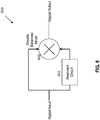
- FIG. 6 illustrates a quadrature demodulator 108 according to certain embodiments of the present disclosure.
- the quadrature demodulator 108 includes a mixer 602 and a resonant circuit 604.
- a double balanced mixer is described, but other suitable types of mixers can also be used.
- the components included in the quadrature demodulator 108 can be further broken down into more than one component and/or combined together in any suitable arrangement. Further, one or more components can be rearranged, changed, added, and/or removed.
- An input signal to the quadrature demodulator 108 is split into two paths. One path is connected to one input port of the double balanced mixer 602, and the other path is connected to the resonant circuit 604.
- the output of the resonant circuit 604 is connected to the other input port of the double balanced mixer 602.
- the resonant circuit 604 includes an inductor and a capacitor.
- the resonant circuit 604 includes an inductor, a capacitor, and a resistor.
- the circuit components of the resonant circuit 604 can be connected in series, in parallel, or any other suitable configuration.
- the resonant circuit 604 can also be implemented by other circuit configurations that are appreciated by a person skilled in the art.
- the resonant circuit 604 is tuned to the nominal center frequency of the electric field generator 104.
- the double balanced mixer 602 multiplies the two signals together (one signal from the input and the other signal from the resonant circuit 604).
- the product of the two signals creates two components in the output: one proportional to the difference between the two input frequencies and another at the sum of the two input frequencies.
- the demodulator output is zero.
- the phase difference is less than about +/- 90 degrees there will be a DC component in the output of the double balanced mixer 602.
- the output signal from the quadrature demodulator 108 is fed to a low pass filter 114.
- the low pass filter 114 is typically an analog circuit that includes resistive, inductive and/or capacitive elements that separates the low frequency component of the quadrature modulator 108 from the much higher frequency component generated by the quadrature modulator 108.
- the cutoff frequency of the low pass filter is selected to provide low attenuation of the desired signal components while sufficiently suppressing the high frequency terms.
- the signal is connected to the signal processor unit 116 described below.
- Detecting changes in electric field dissipation is processed somewhat different from detecting frequency changes in electric field.
- the output of the electric field generator 104 is multiplied by a phase-shifted version of itself produced by the resonant circuit 604. Unlike phase/frequency change detection, amplitude variations must be compared with the electric field generator 104 output unchanged by the material being studied.
- an amplitude reference signal is created by measuring the output of the electric field generator 104 in the absence of any external influence and used to set the output level of the amplitude reference source 106.
- the amplitude reference source 106 is typically a time and temperature stable voltage reference that can be provided by a semiconductor component such as a diode.
- the output of the amplitude reference source 106 is fed to one input of the amplitude comparison switch 110.
- the switch 110 controlled by the signal processor 116, alternately connects the amplitude reference source 106 and electric field generator output 104 to the signal processor 116.
- the amplitude comparison switch 110 functions by sampling the output of the electric field generator 104 at a rate at least twice as fast as the most rapid variation of the amplitude of the electric field generator 104 and subtracting the value of the amplitude reference source 106.
- the output of the amplitude comparison switch 110 is thus equal to the difference between the amplitude of the electric field generator 104 and the amplitude of the amplitude reference source 106.
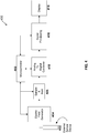
- FIG. 7 illustrates a signal processor 116 according to certain embodiments of the present disclosure.
- the signal processor 116 includes a sample-and-hold circuit 702, an analog-to-digital converter (ADC) 704, a digital signal processor 706, and a microcontroller 708.
- ADC analog-to-digital converter
- the components included in the signal processor 116 can be further broken down into more than one component and/or combined together in any suitable arrangement. Further, one or more components can be rearranged, changed, added, and/or removed.
- the sample-and-hold circuit 702 is configured to sample a continuous-time continuous-value signal and hold the value for a specified period of time.
- a typical sample-and-hold circuit 702 includes a capacitor, one or more switches, and one or more operational amplifier. In some embodiments, other suitable circuit implementations can also be used.
- the ADC 704 receives the output of the sample-and-hold circuit 702 and converts it into digital signals.
- the ADC 410 can have a high resolution. Since the changes in bulk permittivity of the entire region within the electric field in many possible applications are expected to be relatively slow, e.g., less than a few hundred Hertz, in some embodiments it can be sufficient to undersample the output of the electric field generator 404 by using the sample-and-hold device 406 to make short samples that can be processed with the ADC 704 with a sample rate in the five thousand samples/sec range. An ADC with 24-bit resolution or 32-bit resolution are readily available. In some embodiments, the ADC 704 can have other suitable resolutions.
- the digital signal processor 706 can be configured process the output of the ADC 704.
- the digital signal processor 706 can be a microprocessor.
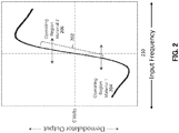
- FIG. 2 shows a generalized version of the transfer function of a quadrature demodulator 108 showing the typical relationship between the voltage output and frequency of the input signal from the electric field generator 104.
- the horizontal axis shows frequency of the in Hertz (Hz), and the vertical axis shows demodulator output in Volt (V).
- the center of the horizontal axis 210 indicates the nominal resonant frequency of the resonant circuit 604. For example, if the nominal resonant frequency of the resonant circuit 604 is 80MHz, then the center of the horizontal axis 210 is at 80MHz.
- the slope of the central region 202 of the curve can be made quite linear to allow operation over an extended frequency range while offering the same sensitivity in terms of output voltage as function of phase/frequency change.
- the transfer function is mathematically dependent only on the frequency/phase relationship between the two inputs to the double-balanced mixer 108. This permits a wide and dynamic range in detection in the phase/frequency changes induced by material properties separate from changes in amplitude due to dissipative properties.
- FIG. 2 illustrates the sensor operating as it might be employed in two different applications while using the same electric field generator 104 and the quadrature demodulator 108.
- the DC component-dependent on the exact value of the frequency and slope of the transfer function-might be, for example, -1.5 volts. If there are small variations in the frequency of the electric field generator 104, there will also be small variations in the quadrature demodulator output voltage. For the example here the output variations will be centered about -1.5 volts.
- the DC term might be, for example, around +1.0 volts. However, since the slope of the transfer function is very close to being the same in both regions, the small variations will be centered around 0 volts.
- the aggregated output of the quadrature demodulator 108 can have a mean DC level determined by the contributions of all materials within the electric field region, while still maintaining an essentially constant transfer function for small changes in material properties.
- the small-signal linearity allows signal components from separate constituents of the material being studied to be linearly combined. Linear combination of the various contributions in the output waveform can be readily separated in later signal processing.
- An example of a combined waveform showing both respiration and heart rate (pulse) signals is shown in FIG. 3 .
- FIG. 4 illustrates a system 400 for detecting and analyzing changes in a body according to certain embodiments of the present disclosure.
- the system 400 includes an external sensor device 402, an electric field generator 404, a sample-and-hold device 406, a microcontroller 408, an ADC 410, a digital signal processor 416, and a display 418.
- the components included in the system 400 can be further broken down into more than one component and/or combined together in any suitable arrangement. Further, one or more components can be rearranged, changed, added, and/or removed. In some embodiments, the components included in FIG. 4 are similar to the corresponding components described in FIG. 1 and/or FIG. 7 .
- the system 400 replaces most analog components described in FIG. 1 with digital or mixed-signal components.
- the "direct-to-digital" concept employs the ADC 410 driven by the sample-and-hold device 406.
- the ADC 410 can have a high resolution. Since the changes in bulk permittivity of the entire region within the electric field in many possible applications are expected to be relatively slow, e.g., less than a few hundred Hertz, it can be sufficient to undersample the output of the electric field generator 404 by using the sample-and-hold device 406 to make short samples that can be processed with the ADC 410 with a sample rate in the five thousand samples/sec range.
- the signal processor 416 would take over the functions performed by the quadrature demodulator 108 described in FIG. 1 . Since the features of the "direct-to-digital" instrument would be determined by the software in the signal processor 416, a single hardware set could be loaded with specialized software for different applications. The programmable characteristics of a "direct-to-digital" approach could enable economies of scale, driving down the unit cost and opening new market opportunities.
- the ADC can be made by an application specific integrated circuit (ASIC).
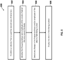
- FIG. 5 is a flow chart illustrating a process 500 of detecting and analyzing changes in a body according to certain embodiments of the present disclosure.
- the process 500 is illustrated in connection with the system 100 shown in FIG. 1 and/or the system 400 shown in FIG. 4 .
- the process 500 can be modified by, for example, having steps rearranged, changed, added, and/or removed.
- an electric field is established around the desired area of detection.
- the desired area of detection is typically around a body that is going to be monitored.
- the electrical field is established by using the electric field generator 104, which creates an electric field that illuminates the desired area of detection.
- the process 500 then proceeds to step 504.
- the frequency and amplitude of the electric field of the desired area of detection are monitored.
- the external sensor device 102 is used to monitor the area around and within the body. The external sensor device 102 is not required to physically contact the body being studied. The process 500 then proceeds to step 506.
- the electric field of the desired area of detection is processed and analyzed to detect any change.
- the process 500 can detect the change of the electric field in both amplitude and frequency/phase. For example, amplitude variations of the electric field can be compared with the electric field generator 104 output unchanged by the material being studied.
- an amplitude reference signal is created by measuring the output of the electric field generator in the absence of any external influence and used to set the output level of the amplitude reference source 106.
- the output of the amplitude reference source 106 is fed to one input of the amplitude comparison switch 110.
- the switch 110 controlled by the signal processor 116, alternately connects the amplitude reference source 106 and electric field generator output 106 to the signal processor.
- the change of the electric field in frequency/phase can be detected and analyzed by the quadrature demodulator configuration discussed in connection with FIG. 1 and FIG. 6 .
- the output of the electric field generator 104 is connected to the quadrature demodulator that is configured to detect the changes of the frequency of the output of the electric field generator 104 and produce a detected response that includes a low frequency component and a high frequency component.
- the detected response is then fed to a low pass filter 114 that is configured to filter out the high frequency component of the detected response to generate a filtered response.
- the changes in phase can be readily derived by people skilled in the art.
- the filtered response and the amplitude comparison response can then be supplied to a signal processor for further analysis.
- the change of the electric field can be analyzed under the "direct-to-digital" approach described in the system 400 in connection with FIG. 4 .
- the output of the electric field generator 404 can be sampled and held by the sample-and-hold device 406 and digitized by the ADC 410.
- the digitized output of the ADC 410 can then be analyzed by the digital signal processor 416.
- the process 500 then proceeds to step 508.
- the electric field can be displayed for visual inspection.
- the changes of the electric field can also be displayed and recorded.
- the changes of the electric field can be extracted to provide specific bodily function features such as vascular processes and conditions, respiration processes and conditions, and other body material characteristics that vary with permittivity.
- the processor can be couple with a memory device, which can be a non-transitory computer readable medium, flash memory, a magnetic disk drive, an optical drive, a PROM, a ROM, or any other memory or combination of memories.
- a memory device can be a non-transitory computer readable medium, flash memory, a magnetic disk drive, an optical drive, a PROM, a ROM, or any other memory or combination of memories.
- the processor can be configured to run a module stored in the memory that is configured to cause the processor to perform various steps that are discussed in the disclosed subject matter.
- changes in capacitor excitation frequency can be remotely sensed to alleviate the need for analog data reduction at the sensor.
- first derivatives can be used to find a recurring pattern in a combined time series signal of heartbeat and respiration such that the respiration signal can be subtracted from the combined signal to leave the heartbeat signal.
- wavelet analysis can be used to disambiguate complex time series data with highly variable frequency compositions. Signals that vary their frequency in time are resistant to effective analysis using traditional digital techniques such as fast Fourier transform (FFT). Wavelets provide the notion of short pattern correlation that can be applied to a sliding window of time series data in order to provide a second correlation time series that indicates the time at which a test pattern or "wavelet" is found within the first time series.
- FFT fast Fourier transform
- a low resolution FFT can be used to peak search for power levels in a correlation function. This FFT power analysis is then used to set the correlation cutoff level and thus determine higher resolution correlated frequencies based on the power levels provides by the FFT.
- the FFT essentially filters out correlations below a particular power level so that more strongly correlated signals can remain. This provides a way of efficiently 'normalizing' the power levels relative to one another in trying to separate low frequency signals that are relatively close in frequency but widely separated in power without having to increase the resolution of the FFT with attendant significantly increased FFT window acquisition time.
- Kalman filters can be used to process the effect of changes in permittivity as indicated by a time series data such that the filter relates the predicted next value in a time series in maintaining a useable moving average for the purposes of normalizing a highly variable signal from a sensor with high dynamic range.
- measurement of the temperature of a body or substance can be obtained by measuring the permittivity of said body or substance where such permittivity may be correlated to temperature.
- measurement of the pressure within a body, substance, and/or liquid can be obtained by measuring the permittivity of said body, substance, and/or liquid where such permittivity may be correlated to pressure.
- stress levels in an individual can be determined by analyzing his or her motion, heartbeat characteristics and respiration using a remote, noncontact, biometric sensor.
- the quality of food in food processing and handling operations can be monitored by correlating the qualities of the food to the measured permittivity of the food item.
- cavities and/or impurities in solid materials can be found. Such application can be used in areas such as the detection of delamination in composite materials, voids in construction materials, entrained contaminants, and/or the quality of fluid mixing.
- contraband enclosed within solid objects can be found.
- the life signs of infants in cribs, pushchairs and/or car seats can be monitored.
- the presence and life signs located in automobiles can be detected for the purposes of providing increased passenger safety, deploying airbags, and/or prevent baby from being left behind.
- the sentience of a driver can be detected by using heartbeat variability.
- gestures such as the head-nod signature motion.
- the life signs in unauthorized locations can be discovered.
- the quality of glass manufacture can be assessed by detecting variations in thickness, poor mixing, and/or the entrainment of impurities and/or.
- the nature of underground/sub-surface texture and infrastructure can be assessed.
- the external sensor device disclosed herein can be combined with other sensors (e.g., camera, echolocation, pressure/weight/accelerometers) to provide enhanced sensor application using sensor "fusion.”
- sensors e.g., camera, echolocation, pressure/weight/accelerometers
- certain body conditions can be detected.
- the body conditions include conditions of the body relating to heart-lung functions, pulmonary fluid levels, blood flow and function, large and small intestine condition and process, bladder condition (full/empty) and process (rate fill/empty), edema and related fluid conditions, bone density measurement, and any other suitable condition or combination of conditions.
Description
- This application relates generally to the technical field of monitoring systems, and more particularly, to a monitoring system that detects physical changes without physical contact.
- The performance of a variety of monitoring systems may be affected by where a sensor or its parts are placed relative to a target (e.g., a human such as an adult, teen, child, or baby) that is being monitored. For example, certain monitoring systems may require a sensor to be in physical contact with a target and may further require a part (e.g., a power or data cable) to be connected from a sensor to a monitoring device. There may be other circumstances in which the sensor might be used to detect changes in occupancy of a vehicle seat. In this case the sensor might also sense vital signs-e.g., pulse and/or respiration-of a seat occupant without direct physical contact.
- Known monitoring systems require a sensor to be directly in contact with a target. For example, a traditional electrocardiogram (ECG) uses external electrodes to detect a patient's ECG signal. The external electrodes are located on the ends of cables and must be physically placed on a patient and near the patient's heart. This often necessitates the use of conductive materials that may be inconvenient to hook up and use, especially for long-term monitoring of a relatively active patient. These devices have significant limitations. For example, the patient must be physically connected to the device. If the patient wants to leave his or her bed, the device needs to be detached from, and then re-attached to the patient on his/her return, often by a highly trained staff member. The inconvenience and the delays associated with setting up such monitoring systems are also not well-suited for monitoring more active targets, for example, a baby in a crib or a person driving a vehicle. Although there are monitoring systems incorporated into devices such as wristbands and armbands they still typically need to be directly in contact with the target, and often provide inaccurate information and limited functionality.
- Accordingly, there is a need for a monitoring system that does not require a sensor to be directly in contact with a target. There is also a need for a monitoring system that can assist in the management of a target's health, fitness, sleep and diet by monitoring physiological changes in a person's body. There is further a need for a monitoring system suitable for long-term use that can sense changes in a target and provide timely and appropriate diagnostic, prognostic and prescriptive information.
- An example of radar based systems as known in the field is given in patent application publication document
US 2010/0152600 A1 . - This invention, the scope of which is defined by the appended claims, includes systems and methods that allow detection of physical changes within a body without physical contact with, or attachment to, the body. A body is a mass of matter distinct from other masses. Non-limiting examples of a body include, for example, a human's body, an animal's body, a container, a car, a house, etc. These changes might be physiological events such as cardiac function in an animal or changes in the properties of a bulk material such as grain in a silo. These changes could be dimensional changes such as those caused by the function of organs in an animal, or changes in the composition of the material such as water content in lumber.
- A key feature of the measurement technique used in this instrument is that the measurement may be done over an extended volume such that the changes of multiple phenomena may be observed simultaneously. For example, sensing two separate but related physiological parameters (e.g., pulse and respiration) may be accomplished concurrently. The region sensed by this instrument may be changed by sensor element design within the instrument. A further extension of bulk sensing capability is the opportunity to use sophisticated computer signature recognition software, such as wavelet-based approaches, to separate individual features from the composite waveform.
- Disclosed subject matter includes, in one aspect, a system for detecting and analyzing changes in a body. The system includes an electric field generator configured to produce an electric field. The system includes an external sensor device, coupled to the electric field generator, configured to detect physical changes in the electric field, where the physical changes affect amplitude and frequency of the electric field. The system includes a quadrature demodulator, coupled to the electric field generator, configured to detect changes of the frequency of the output of the electric field generator and produce a detected response that includes a low frequency component and a high frequency component. The system includes a low pass filter, coupled to the quadrature demodulator, configured to filter out the high frequency component of the detected response to generate a filtered response. The system includes an amplitude reference source configured to provide an amplitude reference. The system includes an amplitude comparison switch, coupled to the amplitude reference source and the electric field generator, configured to compare the amplitude reference and the amplitude of the electric field to generate an amplitude comparison. They system includes a signal processor, coupled to the low pass filter and the amplitude comparison switch, configured to analyze the filtered response and the amplitude comparison response.
- Disclosed subject matter includes, in another aspect, a method for detecting and analyzing changes in a body. The method includes establishing an electric field around a desired area of detection with an electric filed generator. The method includes monitoring frequency of the electrical field with a quadrature demodulator. The method includes detecting changes in the frequency of the electric field with the quadrature demodulator. The method includes monitoring amplitude of the electric field. The method includes detecting changes in the amplitude of the electric field with an amplitude reference source.
- Disclosed subject matter includes, in yet another aspect, a non-transitory computer readable medium having executable instructions operable to cause an apparatus to establish an electric field around a desired area of detection with an electric field generator. The instructions are further operable to cause the apparatus to monitor frequency of the electrical field with a quadrature demodulator. The instructions are further operable to cause the apparatus to detect changes in the frequency of the electric field with the quadrature demodulator. The instructions are further operable to cause the apparatus to monitor amplitude of the electric field. The instructions are further operable to cause the apparatus to detect changes in the amplitude of the electric field with an amplitude reference source.
- Before explaining example embodiments consistent with the present disclosure in detail, it is to be understood that the disclosure is not limited in its application to the details of constructions and to the arrangements set forth in the following description or illustrated in the drawings. The disclosure is capable of embodiments in addition to those described and is capable of being practiced and carried out in various ways. Also, it is to be understood that the phraseology and terminology employed herein, as well as in the abstract, are for the purpose of description and should not be regarded as limiting.
- These and other capabilities of embodiments of the disclosed subject matter will be more fully understood after a review of the following figures, detailed description, and claims.
- It is to be understood that both the foregoing general description and the following detailed description are explanatory only and are not restrictive of the claimed subject matter.
- Various objects, features, and advantages of the disclosed subject matter can be more fully appreciated with reference to the following detailed description of the disclosed subject matter when considered in connection with the following drawings, in which like reference numerals identify like elements.
-
FIG. 1 illustrates a system for detecting and analyzing changes in a body according to certain embodiments of the present disclosure. -
FIG. 2 illustrates a transfer function of a quadrature demodulator according to certain embodiments of the present disclosure. -
FIG. 3 illustrates a waveform combining both respiration and heart rate signals according to certain embodiments of the present disclosure. -
FIG. 4 illustrates a system for detecting and analyzing changes in a body according to certain embodiments of the present disclosure. -
FIG. 5 illustrates a process of detecting and analyzing changes in a body according to certain embodiments of the present disclosure. -
FIG. 6 illustrates a quadrature demodulator according to certain embodiments of the present disclosure. -
FIG. 7 illustrates a signal processor according to certain embodiments of the present disclosure. - The manner in which materials behave in an alternating current ("AC") circuit usually is described in terms of the amount of energy stored in the material and the amount of energy dissipated in the material on a per cycle basis. Energy storage occurs in both electric and magnetic fields created by the current. Dissipation occurs in transformation, in the material, of electrical energy into thermal energy, i.e., heat. These properties can vary over a wide range depending on the material. In many materials the properties are predominantly one type.
- Dissipation in some materials may be attributed to the magnetic field properties of a material and in other cases to the electric field properties. In more general cases, both of these mechanisms are present. Because of this, there is a convention in which the magnetic field storage properties and any related dissipation are combined in a vector sum and called permeability. Similarly, the vector sum of the electric field storage properties and associated dissipation is called permittivity. These vector sums are expressed as complex values in which the dissipation is the real component and field storage properties are the imaginary component. In the present disclosure, the aggregated change in properties of a body are detected and quantified by measuring changes in the body's electromagnetic properties.
- Although the approach described here works by sensing changes in the electromagnetic properties, i.e. changes in both electric and magnetic properties, in some applications the significant changes occur in only one set of properties. For purposes of further discussion, the instrument in this invention detects changes in permittivity. Detection of any other suitable property or combination of properties that are appreciated by a person skilled in the art is also within the spirit and limit of the disclosed subject matter. The dissipative component of permittivity often is expressed as the loss tangent of the material, while the storage term is called capacitance. Measuring these properties is accomplished by sensing the change of phase and amplitude of an electric field generated by the instrument and caused by the aggregated properties of a body within the field.
-
FIG. 1 illustrates asystem 100 for detecting and analyzing changes in a body according to certain embodiments of the present disclosure. Thesystem 100 includes anexternal sensor device 102, anelectric field generator 104, anamplitude reference source 106, aquadrature modulator 108, anamplitude comparison switch 110, alow pass filter 114, asignal processor 116, and adisplay 118. The components included in thesystem 100 can be further broken down into more than one component and/or combined together in any suitable arrangement. Further, one or more components can be rearranged, changed, added, and/or removed. In some embodiments, one or more components of thesystem 100 can be made by an application specific integrated circuit (ASIC). - The
electric field generator 104 creates an electric field that illuminates the desired area of detection. The frequency and amplitude of this electric field is determined by the characteristics of the body being observed. In some embodiments, a frequency-determining component of the electric field generator 104-a resonant circuit than can comprised of a combination of inductive, capacitive, and resistive elements- is connected to an external device that creates the electric field providing the desired coverage of the body of material being studied. In some embodiments, theelectric field generator 104 can be an oscillator, such as an inductor-capacitor (LC) tank oscillator. - The
external sensor device 102 may be made from a wide variety of materials; the only requirement of these materials is that they are electrical conductors. Theexternal sensor device 102 can be constructed in many different mechanical configurations to provide appropriate coverage of the desired region. For example, in some embodiments, theexternal sensor device 102 can be a plurality of metallic plates. In some embodiments, the shape and/or the orientation of theexternal sensor device 102 can be changed as needed. - In some embodiments, the
external sensor device 102 is not required to physically contact the body being studied. For example, theexternal sensor device 102 and the supporting electronics could be installed in the driver's seat of an over-the-highway truck to detect changes in physiological indicators of driver drowsiness and thus take actions to prevent an accident. In some embodiments, the sensing process usually is done separately in two paths: (1) in a first path the changes in the real component of the vector sum, e.g., energy dissipation, are detected; (2) in a second path the changes related to the imaginary component-a component such as a capacitance or inductance in which the phase of the current flowing in them is orthogonal to the current in the real component-are separately processed. In some embodiments, the changes in amplitude of the electric field are detected in the first path, and the changes in frequency of the electric field are detected in the second path. Generally, as known by a person skilled in the art, the changes in phase of the electric field can be obtained by analyzing the changes in frequency of the electric field. These two signals can be combined in later signal processing to re-create the changes in the complex permittivity or kept as individual signals for separate analysis. These two paths are discussed separately below. - To detect changes in the imaginary component of the complex permittivity, the output of the
electric field generator 104 is connected to thequadrature demodulator 108. Thequadrature demodulator 108 detects the changes of the frequency of the output of theelectric field generator 104 and produce a detected response that includes a low frequency component and a high frequency component.FIG. 6 illustrates aquadrature demodulator 108 according to certain embodiments of the present disclosure. Thequadrature demodulator 108 includes amixer 602 and aresonant circuit 604. In the present disclosure, a double balanced mixer is described, but other suitable types of mixers can also be used. The components included in thequadrature demodulator 108 can be further broken down into more than one component and/or combined together in any suitable arrangement. Further, one or more components can be rearranged, changed, added, and/or removed. - An input signal to the
quadrature demodulator 108 is split into two paths. One path is connected to one input port of the doublebalanced mixer 602, and the other path is connected to theresonant circuit 604. The output of theresonant circuit 604 is connected to the other input port of the doublebalanced mixer 602. In some embodiments, theresonant circuit 604 includes an inductor and a capacitor. In some embodiments, theresonant circuit 604 includes an inductor, a capacitor, and a resistor. The circuit components of theresonant circuit 604 can be connected in series, in parallel, or any other suitable configuration. Theresonant circuit 604 can also be implemented by other circuit configurations that are appreciated by a person skilled in the art. In some embodiments, theresonant circuit 604 is tuned to the nominal center frequency of theelectric field generator 104. - The double
balanced mixer 602 multiplies the two signals together (one signal from the input and the other signal from the resonant circuit 604). The product of the two signals creates two components in the output: one proportional to the difference between the two input frequencies and another at the sum of the two input frequencies. When there is an exact 90-degree phase difference between the two signals, the demodulator output is zero. When the phase difference is less than about +/- 90 degrees there will be a DC component in the output of the doublebalanced mixer 602. - The output signal from the quadrature demodulator 108is fed to a
low pass filter 114. Thelow pass filter 114 is typically an analog circuit that includes resistive, inductive and/or capacitive elements that separates the low frequency component of thequadrature modulator 108 from the much higher frequency component generated by thequadrature modulator 108. The cutoff frequency of the low pass filter is selected to provide low attenuation of the desired signal components while sufficiently suppressing the high frequency terms. After filtering, the signal is connected to thesignal processor unit 116 described below. - Detecting changes in electric field dissipation is processed somewhat different from detecting frequency changes in electric field. In
FIGs. 1 and6 , the output of theelectric field generator 104 is multiplied by a phase-shifted version of itself produced by theresonant circuit 604. Unlike phase/frequency change detection, amplitude variations must be compared with theelectric field generator 104 output unchanged by the material being studied. Referring again toFIG. 1 , an amplitude reference signal is created by measuring the output of theelectric field generator 104 in the absence of any external influence and used to set the output level of theamplitude reference source 106. - The
amplitude reference source 106 is typically a time and temperature stable voltage reference that can be provided by a semiconductor component such as a diode. The output of theamplitude reference source 106 is fed to one input of theamplitude comparison switch 110. Theswitch 110, controlled by thesignal processor 116, alternately connects theamplitude reference source 106 and electricfield generator output 104 to thesignal processor 116. By measuring the difference between thereference signal 106 and theelectric field generator 104 output - and with sufficient calibration information - the amount of power absorbed, e.g., dissipated, by the material under study may be computed. - The
amplitude comparison switch 110 functions by sampling the output of theelectric field generator 104 at a rate at least twice as fast as the most rapid variation of the amplitude of theelectric field generator 104 and subtracting the value of theamplitude reference source 106. The output of theamplitude comparison switch 110 is thus equal to the difference between the amplitude of theelectric field generator 104 and the amplitude of theamplitude reference source 106. - The
signal processor 116 takes the output of thelow pass filter 114 and extracts the desired components into desired formats for further use or processing. Thesignal processor 116 also takes the output of theamplitude comparison switch 110 to analyze the changes in amplitude of the electric field. Thesignal processor 116 can be implemented by use of either analog, digital, or combined circuits. -
FIG. 7 illustrates asignal processor 116 according to certain embodiments of the present disclosure. Thesignal processor 116 includes a sample-and-hold circuit 702, an analog-to-digital converter (ADC) 704, adigital signal processor 706, and amicrocontroller 708. The components included in thesignal processor 116 can be further broken down into more than one component and/or combined together in any suitable arrangement. Further, one or more components can be rearranged, changed, added, and/or removed. - The sample-and-
hold circuit 702 is configured to sample a continuous-time continuous-value signal and hold the value for a specified period of time. A typical sample-and-hold circuit 702 includes a capacitor, one or more switches, and one or more operational amplifier. In some embodiments, other suitable circuit implementations can also be used. - The
ADC 704 receives the output of the sample-and-hold circuit 702 and converts it into digital signals. In some embodiments, theADC 410 can have a high resolution. Since the changes in bulk permittivity of the entire region within the electric field in many possible applications are expected to be relatively slow, e.g., less than a few hundred Hertz, in some embodiments it can be sufficient to undersample the output of theelectric field generator 404 by using the sample-and-hold device 406 to make short samples that can be processed with theADC 704 with a sample rate in the five thousand samples/sec range. An ADC with 24-bit resolution or 32-bit resolution are readily available. In some embodiments, theADC 704 can have other suitable resolutions. - The
digital signal processor 706 can be configured process the output of theADC 704. In some embodiments, thedigital signal processor 706 can be a microprocessor. - The
microcontroller 708 can be coupled to one or more components of thesignal processor 116. In some embodiments, themicrocontroller 708 can control the sampling rate and/or clock rate of the one or more components of thesignal processor 116. In some embodiments, themicrocontroller 708 can issue command signals to the one or more components of thesignal processor 116. In some embodiments, themicrocontroller 708 can be a generic high performance low power system on chip (SOC) product. For example, themicrocontroller 708 can be an ARM based processor, such as an ARM Cortex-M4 core processor or any other suitable models. - Referring to the
display 118, thedisplay 118 can be configured to display various results generated by thesignal processor 116. Thedisplay 118 can be a touch screen, an LCD screen, and/or any other suitable display screen or combination of display screens. In some embodiments, the output of thesignal processor 116 can also be fed to a data logger for signal storage and/or processing. -
FIG. 2 shows a generalized version of the transfer function of aquadrature demodulator 108 showing the typical relationship between the voltage output and frequency of the input signal from theelectric field generator 104. The horizontal axis shows frequency of the in Hertz (Hz), and the vertical axis shows demodulator output in Volt (V). The center of thehorizontal axis 210 indicates the nominal resonant frequency of theresonant circuit 604. For example, if the nominal resonant frequency of theresonant circuit 604 is 80MHz, then the center of thehorizontal axis 210 is at 80MHz. The slope of thecentral region 202 of the curve can be made quite linear to allow operation over an extended frequency range while offering the same sensitivity in terms of output voltage as function of phase/frequency change. The transfer function is mathematically dependent only on the frequency/phase relationship between the two inputs to the double-balanced mixer 108. This permits a wide and dynamic range in detection in the phase/frequency changes induced by material properties separate from changes in amplitude due to dissipative properties. -
FIG. 2 illustrates the sensor operating as it might be employed in two different applications while using the sameelectric field generator 104 and thequadrature demodulator 108. InRegion 1 204, the DC component-dependent on the exact value of the frequency and slope of the transfer function-might be, for example, -1.5 volts. If there are small variations in the frequency of theelectric field generator 104, there will also be small variations in the quadrature demodulator output voltage. For the example here the output variations will be centered about -1.5 volts. InRegion 2 206, the DC term might be, for example, around +1.0 volts. However, since the slope of the transfer function is very close to being the same in both regions, the small variations will be centered around 0 volts. - This is an important benefit to the approach taken here. If there are a wide variety of materials, each with varying electromagnetic properties within the electric field, the aggregated output of the
quadrature demodulator 108 can have a mean DC level determined by the contributions of all materials within the electric field region, while still maintaining an essentially constant transfer function for small changes in material properties. The small-signal linearity allows signal components from separate constituents of the material being studied to be linearly combined. Linear combination of the various contributions in the output waveform can be readily separated in later signal processing. An example of a combined waveform showing both respiration and heart rate (pulse) signals is shown inFIG. 3 . -
FIG. 3 shows a signal comprised of a large, low frequency, roughly triangular waveform that might be typical of respiration by a body and a signal often seen in a heart pulse of smaller amplitude, higher frequency, and more complex waveform. InFIG. 3 the linear addition of these two waveforms is shown as the smaller amplitude, higher frequency, more complex heart pulse "riding" on the larger, slower triangular respiration component. - In addition to the largely analog design described above, a "direct-to-digital" approach is also possible.
FIG. 4 illustrates asystem 400 for detecting and analyzing changes in a body according to certain embodiments of the present disclosure. Thesystem 400 includes anexternal sensor device 402, anelectric field generator 404, a sample-and-hold device 406, a microcontroller 408, anADC 410, adigital signal processor 416, and adisplay 418. The components included in thesystem 400 can be further broken down into more than one component and/or combined together in any suitable arrangement. Further, one or more components can be rearranged, changed, added, and/or removed. In some embodiments, the components included inFIG. 4 are similar to the corresponding components described inFIG. 1 and/orFIG. 7 . - In some embodiments, the
system 400 replaces most analog components described inFIG. 1 with digital or mixed-signal components. The "direct-to-digital" concept employs theADC 410 driven by the sample-and-hold device 406. In some embodiments, theADC 410 can have a high resolution. Since the changes in bulk permittivity of the entire region within the electric field in many possible applications are expected to be relatively slow, e.g., less than a few hundred Hertz, it can be sufficient to undersample the output of theelectric field generator 404 by using the sample-and-hold device 406 to make short samples that can be processed with theADC 410 with a sample rate in the five thousand samples/sec range. Such devices with 24-bit resolution are readily available, as are 32-bit versions at a significantly higher component price. In such a system, thesignal processor 416 would take over the functions performed by thequadrature demodulator 108 described inFIG. 1 . Since the features of the "direct-to-digital" instrument would be determined by the software in thesignal processor 416, a single hardware set could be loaded with specialized software for different applications. The programmable characteristics of a "direct-to-digital" approach could enable economies of scale, driving down the unit cost and opening new market opportunities. In some embodiments, the ADC can be made by an application specific integrated circuit (ASIC). -
FIG. 5 is a flow chart illustrating aprocess 500 of detecting and analyzing changes in a body according to certain embodiments of the present disclosure. Theprocess 500 is illustrated in connection with thesystem 100 shown inFIG. 1 and/or thesystem 400 shown inFIG. 4 . In some embodiments, theprocess 500 can be modified by, for example, having steps rearranged, changed, added, and/or removed. - At
step 502, an electric field is established around the desired area of detection. The desired area of detection is typically around a body that is going to be monitored. In some embodiments, the electrical field is established by using theelectric field generator 104, which creates an electric field that illuminates the desired area of detection. Theprocess 500 then proceeds to step 504. - At
step 504, the frequency and amplitude of the electric field of the desired area of detection are monitored. In some embodiments, theexternal sensor device 102 is used to monitor the area around and within the body. Theexternal sensor device 102 is not required to physically contact the body being studied. Theprocess 500 then proceeds to step 506. - At
step 506, the electric field of the desired area of detection is processed and analyzed to detect any change. Theprocess 500 can detect the change of the electric field in both amplitude and frequency/phase. For example, amplitude variations of the electric field can be compared with theelectric field generator 104 output unchanged by the material being studied. Referring again toFIG. 1 , an amplitude reference signal is created by measuring the output of the electric field generator in the absence of any external influence and used to set the output level of theamplitude reference source 106. The output of theamplitude reference source 106 is fed to one input of theamplitude comparison switch 110. Theswitch 110, controlled by thesignal processor 116, alternately connects theamplitude reference source 106 and electricfield generator output 106 to the signal processor. By measuring the difference between the reference signal and theelectric field generator 104 output -- and with sufficient calibration information - the amplitude comparison response of the electric field can be determined. - The change of the electric field in frequency/phase can be detected and analyzed by the quadrature demodulator configuration discussed in connection with
FIG. 1 andFIG. 6 . For example, in some embodiments, the output of theelectric field generator 104 is connected to the quadrature demodulator that is configured to detect the changes of the frequency of the output of theelectric field generator 104 and produce a detected response that includes a low frequency component and a high frequency component. The detected response is then fed to alow pass filter 114 that is configured to filter out the high frequency component of the detected response to generate a filtered response. In some embodiments, once the changes in frequency is detected, the changes in phase can be readily derived by people skilled in the art. - The filtered response and the amplitude comparison response can then be supplied to a signal processor for further analysis.
- In some embodiments, the change of the electric field can be analyzed under the "direct-to-digital" approach described in the
system 400 in connection withFIG. 4 . The output of theelectric field generator 404 can be sampled and held by the sample-and-hold device 406 and digitized by theADC 410. The digitized output of theADC 410 can then be analyzed by thedigital signal processor 416. Theprocess 500 then proceeds to step 508. - At
step 508, the electric field can be displayed for visual inspection. In some embodiments, the changes of the electric field can also be displayed and recorded. In some embodiments, the changes of the electric field can be extracted to provide specific bodily function features such as vascular processes and conditions, respiration processes and conditions, and other body material characteristics that vary with permittivity. - In some embodiments, the
system 100 or thesystem 400 can include a processor, which can include one or more cores and can accommodate one or more threads to run various applications and modules. The software can run on the processor capable of executing computer instructions or computer code. The processor may also be implemented in hardware using an application specific integrated circuit (ASIC), programmable logic array (PLA), field programmable gate array (FPGA), or any other integrated circuit. - The processor can be couple with a memory device, which can be a non-transitory computer readable medium, flash memory, a magnetic disk drive, an optical drive, a PROM, a ROM, or any other memory or combination of memories.
- The processor can be configured to run a module stored in the memory that is configured to cause the processor to perform various steps that are discussed in the disclosed subject matter.
- The following applications and/or methods are non-limiting examples of applying the disclosed subject matter.
- In some embodiments, changes in capacitor excitation frequency can be remotely sensed to alleviate the need for analog data reduction at the sensor.
- In some embodiments, blood pressure can be measured by isolating a body region using a pressure "doughnut" and then releasing pressure and monitoring the return of blood flow as a result. Traditional means enclosing a limb to close an artery and monitor the pressure at which the artery opens up as the pressure is released. With the disclosed invention, a body region can be determined that excludes blood by closing capillaries (within the 'doughnut' pressure region) and monitoring the pressure at which they then open again. This simplification of application could then be applied to in-seat circumstances in hospital/clinic waiting rooms and the like.
- In some embodiments, first derivatives can be used to find a recurring pattern in a combined time series signal of heartbeat and respiration such that the respiration signal can be subtracted from the combined signal to leave the heartbeat signal.
- In some embodiments, the mathematical notion of Entropy (H) can be used to analyze a heartbeat signal and extract event timing information with respect to characterizing heart processes.
- In some embodiments, wavelet analysis can be used to disambiguate complex time series data with highly variable frequency compositions. Signals that vary their frequency in time are resistant to effective analysis using traditional digital techniques such as fast Fourier transform (FFT). Wavelets provide the notion of short pattern correlation that can be applied to a sliding window of time series data in order to provide a second correlation time series that indicates the time at which a test pattern or "wavelet" is found within the first time series.
- In some embodiments, a low resolution FFT can be used to peak search for power levels in a correlation function. This FFT power analysis is then used to set the correlation cutoff level and thus determine higher resolution correlated frequencies based on the power levels provides by the FFT. The FFT essentially filters out correlations below a particular power level so that more strongly correlated signals can remain. This provides a way of efficiently 'normalizing' the power levels relative to one another in trying to separate low frequency signals that are relatively close in frequency but widely separated in power without having to increase the resolution of the FFT with attendant significantly increased FFT window acquisition time.
- In some embodiments, Kalman filters can be used to process the effect of changes in permittivity as indicated by a time series data such that the filter relates the predicted next value in a time series in maintaining a useable moving average for the purposes of normalizing a highly variable signal from a sensor with high dynamic range.
- In some embodiments, measurement of the temperature of a body or substance can be obtained by measuring the permittivity of said body or substance where such permittivity may be correlated to temperature.
- In some embodiments, measurement of the pressure within a body, substance, and/or liquid can be obtained by measuring the permittivity of said body, substance, and/or liquid where such permittivity may be correlated to pressure.
- In some embodiments, stress levels in an individual can be determined by analyzing his or her motion, heartbeat characteristics and respiration using a remote, noncontact, biometric sensor.
- In some embodiments, the quality of food in food processing and handling operations can be monitored by correlating the qualities of the food to the measured permittivity of the food item.
- In some embodiments, the characteristics (e.g., turbulence, flow, density, temperature) of a fluid (e.g., paint, blood, reagents, petroleum products) can be monitored by correlating the characteristics of the fluid to the objective characteristics of the fluid.
- In some embodiments, cavities and/or impurities in solid materials can be found. Such application can be used in areas such as the detection of delamination in composite materials, voids in construction materials, entrained contaminants, and/or the quality of fluid mixing.
- In some embodiments, contraband enclosed within solid objects can be found.
- In some embodiments, the life signs of infants in cribs, pushchairs and/or car seats can be monitored.
- In some embodiments, the presence and life signs located in automobiles can be detected for the purposes of providing increased passenger safety, deploying airbags, and/or prevent baby from being left behind.
- In some embodiments, the sentience of a driver can be detected by using heartbeat variability. In some embodiments, gestures such as the head-nod signature motion.
- In some embodiments, the life signs in unauthorized locations (e.g., smuggling and/or trafficking) can be discovered.
- In some embodiments, the quality of glass manufacture can be assessed by detecting variations in thickness, poor mixing, and/or the entrainment of impurities and/or.
- In some embodiments, the nature of underground/sub-surface texture and infrastructure (pipes and similar) can be assessed.
- In some embodiments, the external sensor device disclosed herein can be combined with other sensors (e.g., camera, echolocation, pressure/weight/accelerometers) to provide enhanced sensor application using sensor "fusion."
- In some embodiments, certain body conditions can be detected. The body conditions include conditions of the body relating to heart-lung functions, pulmonary fluid levels, blood flow and function, large and small intestine condition and process, bladder condition (full/empty) and process (rate fill/empty), edema and related fluid conditions, bone density measurement, and any other suitable condition or combination of conditions.
- It is to be understood that the disclosed subject matter is not limited in its application to the details of construction and to the arrangements of the components set forth in the following description or illustrated in the drawings. The disclosed subject matter is capable of other embodiments and of being practiced and carried out in various ways. Also, it is to be understood that the phraseology and terminology employed herein are for the purpose of description and should not be regarded as limiting.
- As such, those skilled in the art will appreciate that the conception, upon which this disclosure is based, may readily be utilized as a basis for the designing of other structures, systems, methods, and media for carrying out the several purposes of the disclosed subject matter.
- Although the disclosed subject matter has been described and illustrated in the foregoing exemplary embodiments, it is understood that the present disclosure has been made only by way of example, and that numerous changes in the details of implementation of the disclosed subject matter may be made. The scope of the present invention is defined by the appended claims.
Claims (15)
- A system for detecting and analyzing changes in a body, comprising:an electric field generator (104) configured to produce an electric field;an external sensor device (102), coupled to the electric field generator, configured to detect physical changes in the electric field, wherein the physical changes affect amplitude and frequency of the electric field;a quadrature demodulator (108), coupled to the electric field generator, configured to detect changes of the frequency of the output of the electric field generator and produce a detected response that includes a low frequency component and a high frequency component;a low pass filter (114), coupled to the quadrature demodulator, configured to filter out the high frequency component of the detected response to generate a filtered response;an amplitude reference source (106) configured to provide an amplitude reference;an amplitude comparison switch (110), coupled to the amplitude reference source and the electric field generator, configured to compare the amplitude reference and the amplitude of the electric field to generate an amplitude comparison response;and a signal processor (106), coupled to the low pass filter and the amplitude comparison switch, configured to analyze the filtered response and the amplitude comparison response.
- The system of claim 1, wherein the signal processor comprises:a sample-and-hold circuit configured to sample the filtered response and the amplitude comparison response;an analog-to-digital converter (ADC), coupled to the sample-and-hold circuit, configured to digitize an output of the sample-and-hold circuit;and a digital signal processor, coupled to the ADC, configured to analyze an output of the ADC.
- The system of claim 1, wherein the quadrature demodulator comprises:a resonant circuit configured to produce a quadrature input based on the input of the quadrature demodulator;and a mixer, coupled to the resonant circuit, configured to (1) mix the input of the quadrature demodulator and the quadrature input and (2) generate an output of the quadrature demodulator.
- The system of claim 3, wherein the resonant circuit comprises:a capacitor;an inductor;and a resistor, and optionally or preferably, wherein the capacitor, the inductor, and the resistor are connected in parallel.
- The system of claim 3, wherein the mixer is a balanced mixer, and optionally or preferably wherein the balanced mixer is a double balanced mixer.
- The system of claim 1, wherein the electric field generator comprises an oscillator.
- The system of claim 6, wherein the oscillator is an inductor-capacitor tank oscillator.
- The system of claim 1, wherein the external sensor device comprises a plurality of metallic plates.
- The system of claim 1, wherein the external sensor device is configured to change its orientation.
- The system of claim 1, further comprising a display.
- A method for detecting and analyzing changes in a body, the method comprising:establishing, by an electric field generator (104), an electric field around a desired area of detection of the body with the electric field generator;detecting, by an external sensor device (102), physical changes in the body in the electric field, wherein the physical changes affect amplitude and frequency of the electric field;monitoring and detecting, by a quadrature demodulator (108), changes in the frequency of the electrical field and producing a detected response with frequency components;generating, by a filter (114), a filtered response based on the frequency components;generating an amplitude comparison response by using an amplitude comparison switch (110) to compare the amplitude of the electric field with and amplitude reference from an amplitude reference source (106); andanalyzing, by a processor (116), the filtered response and the amplitude comparison response for detecting the physical changes in the body.
- The method of claim 11, further comprising displaying the changes in at least the amplitude or the frequency of the electric field.
- The method of claim 11, wherein detecting the changes in the amplitude of the electric field further comprises comparing the amplitude of the electric field with the amplitude reference produced by the amplitude reference source.
- The method of claim 11, wherein detecting the changes in the frequency of the electric field further comprises:detecting the changes of the frequency of the electric field and producing a detected response that includes a low frequency component and a high frequency component;and filtering out the high frequency component of the detected response to generate a filtered response.
- A non-transitory computer readable medium storing executable instructions operable for detecting and analyzing changes in a body to cause a processor to perform operations comprising:establishing, by an electric field generator (104), an electric field around a desired area of detection of the body;detecting, by an external sensor device (102), physical changes in the body in the electric field, wherein the physical changes affect amplitude and frequency of the electric field;monitoring and detecting, by a quadrature demodulator (108), changes in the frequency of the electrical field and producing a detected response with frequency components; generating, by a filter, a filtered response based on the frequency components;generating an amplitude comparison response by using an amplitude comparison switch (110) to compare the amplitude of the electric field with and amplitude reference from an amplitude reference source (106); andanalyzing, by a processor (116), the filtered response and the amplitude comparison response for detecting the physical changes in the body.
Applications Claiming Priority (2)
| Application Number | Priority Date | Filing Date | Title |
|---|---|---|---|
| US201662287598P | 2016-01-27 | 2016-01-27 | |
| PCT/US2017/015345 WO2017132514A1 (en) | 2016-01-27 | 2017-01-27 | Systems and methods for detecting physical changes without physical contract |
Publications (3)
| Publication Number | Publication Date |
|---|---|
| EP3407778A1 EP3407778A1 (en) | 2018-12-05 |
| EP3407778A4 EP3407778A4 (en) | 2019-09-18 |
| EP3407778B1 true EP3407778B1 (en) | 2021-01-06 |
Family
ID=59360036
Family Applications (1)
| Application Number | Title | Priority Date | Filing Date |
|---|---|---|---|
| EP17744973.3A Active EP3407778B1 (en) | 2016-01-27 | 2017-01-27 | Systems and methods for detecting physical changes without physical contact |
Country Status (8)
| Country | Link |
|---|---|
| US (4) | US10080507B2 (en) |
| EP (1) | EP3407778B1 (en) |
| JP (2) | JP7081735B2 (en) |
| KR (1) | KR20180105202A (en) |
| CN (1) | CN108601531A (en) |
| CA (1) | CA3012319A1 (en) |
| ES (1) | ES2863241T3 (en) |
| WO (1) | WO2017132514A1 (en) |
Cited By (1)
| Publication number | Priority date | Publication date | Assignee | Title |
|---|---|---|---|---|
| US11523745B2 (en) | 2016-01-27 | 2022-12-13 | Life Detection Technologies, Inc. | Systems and methods for detecting physical changes without physical contact |
Families Citing this family (7)
| Publication number | Priority date | Publication date | Assignee | Title |
|---|---|---|---|---|
| US10631752B2 (en) | 2016-01-27 | 2020-04-28 | Life Detection Technologies, Inc. | Systems and methods for detecting physical changes without physical contact |
| KR20220009931A (en) * | 2018-09-24 | 2022-01-25 | 라이프 디텍션 테크놀로지스, 인크. | Systems and methods for detecting physical changes without physical contact |
| BE1026732B1 (en) * | 2018-10-26 | 2020-06-03 | Phoenix Contact Gmbh & Co | Measuring device |
| JP7217470B2 (en) * | 2019-11-08 | 2023-02-03 | 株式会社アイシン | Heartbeat signal detection device and heartbeat signal detection program |
| WO2023107865A1 (en) * | 2021-12-06 | 2023-06-15 | Life Detection Technologies, Inc. | Computation of parameters of a body using an electric field |
| WO2023107866A2 (en) | 2021-12-06 | 2023-06-15 | Life Detection Technologies, Inc. | Computation of parameters of a body using an electric field |
| WO2023107864A1 (en) * | 2021-12-06 | 2023-06-15 | Life Detection Technologies, Inc. | Computation of parameters of a body using an electric field |
Family Cites Families (86)
| Publication number | Priority date | Publication date | Assignee | Title |
|---|---|---|---|---|
| US4182315A (en) | 1977-07-21 | 1980-01-08 | Diamond George A | Apparatus and method for detection of body tissue movement |
| GB2062239B (en) * | 1979-10-27 | 1984-08-30 | Vas R Forrester J | Detection of body tissue movement |
| US4532501A (en) * | 1982-02-02 | 1985-07-30 | E. I. Du Pont De Nemours And Company | Capacitively coupled machine tool safety system |
| JPS60142274A (en) * | 1983-12-29 | 1985-07-27 | Kokusai Denshin Denwa Co Ltd <Kdd> | Comparing and measuring system |
| US4788869A (en) | 1986-06-27 | 1988-12-06 | Florida State University | Apparatus for measuring fluid flow |
| US4958638A (en) * | 1988-06-30 | 1990-09-25 | Georgia Tech Research Corporation | Non-contact vital signs monitor |
| US5434887A (en) * | 1992-08-25 | 1995-07-18 | Nec Corporation | Quadrature modulation circuit for use in a radio transmitter |
| JPH07288551A (en) * | 1994-04-19 | 1995-10-31 | Alps Electric Co Ltd | Fsk demodulation circuit |
| US7421321B2 (en) * | 1995-06-07 | 2008-09-02 | Automotive Technologies International, Inc. | System for obtaining vehicular information |
| JP3003600B2 (en) * | 1996-11-20 | 2000-01-31 | 日本電気株式会社 | FM demodulation circuit |
| US20020013538A1 (en) | 1997-09-30 | 2002-01-31 | David Teller | Method and apparatus for health signs monitoring |
| JP3663565B2 (en) * | 1997-11-10 | 2005-06-22 | 富士通株式会社 | Carrier recovery circuit |
| JP3568102B2 (en) | 1998-07-24 | 2004-09-22 | 松下電器産業株式会社 | Direct conversion receiver |
| US6807407B2 (en) | 2000-09-11 | 2004-10-19 | Scientific Components, Inc. | Dual double balanced mixer |
| US6679830B2 (en) | 2001-02-06 | 2004-01-20 | Hill-Rom Services, Inc. | Infant incubator with non-contact sensing and monitoring |
| US7109726B2 (en) * | 2001-07-25 | 2006-09-19 | Koninklijke Philips Electronics N.V. | Object sensing |
| GB0129390D0 (en) | 2001-12-07 | 2002-01-30 | Clark Terrence D | Electrodynamic sensors and applications thereof |
| US6856125B2 (en) * | 2001-12-12 | 2005-02-15 | Lifescan, Inc. | Biosensor apparatus and method with sample type and volume detection |
| GB2385132A (en) * | 2002-02-12 | 2003-08-13 | Seiko Epson Corp | A capacitance sensor |
| WO2003101061A1 (en) | 2002-05-24 | 2003-12-04 | Anritsu Corporation | Quadrature modulator carrier quadrature error detection method and quadrature modulation device |
| JP4385274B2 (en) * | 2002-10-29 | 2009-12-16 | ソニー株式会社 | Walking waveform feature extraction method and personal identification device |
| GB0226404D0 (en) * | 2002-11-12 | 2002-12-18 | Koninkl Philips Electronics Nv | Object sensing |
| US20040100376A1 (en) | 2002-11-26 | 2004-05-27 | Kimberly-Clark Worldwide, Inc. | Healthcare monitoring system |
| US7154275B2 (en) | 2002-12-10 | 2006-12-26 | Bae Systems Information And Electronic Systems Integration Inc. | Method and apparatus for detecting individuals using electrical field sensors |
| EP1592344A4 (en) | 2003-01-31 | 2006-08-16 | Univ Leland Stanford Junior | Detection of apex motion for monitoring cardiac dysfunction |
| US7445605B2 (en) | 2003-01-31 | 2008-11-04 | The Board Of Trustees Of The Leland Stanford Junior University | Detection of apex motion for monitoring cardiac dysfunction |
| US8009045B2 (en) * | 2005-06-06 | 2011-08-30 | Cehelnik Thomas G | Method for alerting physical approach |
| FI20030213A0 (en) | 2003-02-12 | 2003-02-12 | Nokia Corp | Selection of operating modes in the electronic device |
| US7383071B1 (en) | 2003-04-25 | 2008-06-03 | United States Of America As Represented By The Secretary Of The Navy | Microsensor system and method for measuring data |
| US7126435B2 (en) * | 2003-09-23 | 2006-10-24 | Rambus Inc. | Voltage controlled oscillator amplitude control circuit |
| US20060154642A1 (en) | 2004-02-20 | 2006-07-13 | Scannell Robert F Jr | Medication & health, environmental, and security monitoring, alert, intervention, information and network system with associated and supporting apparatuses |
| US7173525B2 (en) | 2004-07-23 | 2007-02-06 | Innovalarm Corporation | Enhanced fire, safety, security and health monitoring and alarm response method, system and device |
| CN101120527B (en) * | 2005-02-17 | 2012-09-05 | 皇家飞利浦电子股份有限公司 | Device capable of being operated within a network, network system, method of operating a device within a network |
| US20090048500A1 (en) | 2005-04-20 | 2009-02-19 | Respimetrix, Inc. | Method for using a non-invasive cardiac and respiratory monitoring system |
| EP1895897A2 (en) | 2005-05-26 | 2008-03-12 | Yissum Research Development Company Of The Hebrew University Of Jerusalem | Method and system for determination of physiological conditions and emotional states |
| US8162834B2 (en) * | 2006-10-18 | 2012-04-24 | Board Of Regents, The University Of Texas System | Hemoglobin contrast in ultrasound and optical coherence tomography for diagnosing diseased tissue, cancers, and the like |
| SG129314A1 (en) | 2005-08-02 | 2007-02-26 | Ecospec Global Stechnology Pte | Method and device for water treatment using an electromagnetic field |
| WO2007029138A2 (en) * | 2005-09-07 | 2007-03-15 | Philips Intellectual Property & Standards Gmbh | System and method for inductively measuring the bio-impedance of a conductive tissue |
| JP2008521001A (en) * | 2005-11-22 | 2008-06-19 | ゼファー テクノロジー リミティド | Electric field detector |
| US8502729B2 (en) | 2006-01-30 | 2013-08-06 | Lawrence Livermore National Security, Llc | Ultra-wideband radar sensors and networks |
| US7558622B2 (en) | 2006-05-24 | 2009-07-07 | Bao Tran | Mesh network stroke monitoring appliance |
| US20080077015A1 (en) | 2006-05-17 | 2008-03-27 | Olga Boric-Lubecke | Determining presence and/or physiological motion of one or more subjects with multiple receiver Doppler radar systems |
| US7375664B2 (en) * | 2006-06-07 | 2008-05-20 | Texas Instruments Incorporated | Systems and methods for providing anti-aliasing in a sample-and-hold circuit |
| WO2008036396A2 (en) * | 2006-09-21 | 2008-03-27 | Noninvasive Medical Technologies, Inc. | Apparatus and method for non-invasive thoracic radio interrogation |
| US9261474B2 (en) | 2012-12-28 | 2016-02-16 | General Electric Company | Methods for analysis of fluids |
| US10746680B2 (en) * | 2006-11-16 | 2020-08-18 | General Electric Company | Sensing system and method |
| EP3415090A1 (en) * | 2007-09-05 | 2018-12-19 | Sensible Medical Innovations Ltd. | Method, system and apparatus for using electromagnetic radiation for monitoring a tissue of a user |
| US8130002B2 (en) * | 2007-10-18 | 2012-03-06 | Pioneer Corporation | Device and method for detecting direction of polarization of ferroelectric material |
| FR2923150B1 (en) | 2007-11-07 | 2012-01-13 | Imra Europ Sas | SYSTEM FOR MEASURING THE HEART RATE OF A USER |
| RU2369323C1 (en) * | 2008-02-20 | 2009-10-10 | Игорь Яковлевич Иммореев | Impulse superwide-band sensor |
| US20090240160A1 (en) | 2008-03-19 | 2009-09-24 | Thompson Loren M | Infant monitoring system |
| CA2720871A1 (en) * | 2008-04-03 | 2009-10-08 | Kai Medical, Inc. | Non-contact physiologic motion sensors and methods for use |
| US20100152600A1 (en) * | 2008-04-03 | 2010-06-17 | Kai Sensors, Inc. | Non-contact physiologic motion sensors and methods for use |
| US8882684B2 (en) | 2008-05-12 | 2014-11-11 | Earlysense Ltd. | Monitoring, predicting and treating clinical episodes |
| US8989837B2 (en) * | 2009-12-01 | 2015-03-24 | Kyma Medical Technologies Ltd. | Methods and systems for determining fluid content of tissue |
| US7952425B2 (en) | 2008-09-11 | 2011-05-31 | Siemens Medical Solutions Usa, Inc. | Adaptive filtering system for patient signal monitoring |
| US8482545B2 (en) | 2008-10-02 | 2013-07-09 | Wacom Co., Ltd. | Combination touch and transducer input system and method |
| JP5423023B2 (en) * | 2009-02-06 | 2014-02-19 | 富士ゼロックス株式会社 | Object detection device |
| US8994536B2 (en) | 2009-02-25 | 2015-03-31 | Xanthia Global Limited | Wireless physiology monitor |
| US8274386B1 (en) | 2009-03-23 | 2012-09-25 | The United States Of America As Represented By The Secretary Of The Navy | Human presence electric field sensor |
| KR101610109B1 (en) | 2009-05-19 | 2016-04-11 | 삼성전자주식회사 | Method and Apparatus for tracking input position using E-Field Communication |
| DE102010041571B4 (en) | 2010-09-28 | 2012-11-22 | Hauni Maschinenbau Ag | Apparatus and method for processing and measuring properties of a moving strand of material |
| JP5734740B2 (en) * | 2011-05-23 | 2015-06-17 | 株式会社豊田中央研究所 | Elastic wave detection device and elastic wave detection program |
| JP5846204B2 (en) * | 2011-07-26 | 2016-01-20 | 住友電気工業株式会社 | Compensation device, signal generator, and wireless communication device |
| US20150031964A1 (en) | 2012-02-22 | 2015-01-29 | Aclaris Medical, Llc | Physiological signal detecting device and system |
| US9060745B2 (en) | 2012-08-22 | 2015-06-23 | Covidien Lp | System and method for detecting fluid responsiveness of a patient |
| US9549682B2 (en) * | 2012-08-24 | 2017-01-24 | Life Detection Technologies, Inc. | Systems and methods for monitoring vital signs based on sensed changes in a target |
| US9035778B2 (en) * | 2012-08-24 | 2015-05-19 | Life Detection Systems, Inc. | Monitoring vital signs based on sensed changes to an electrical field |
| US9285889B2 (en) | 2012-12-10 | 2016-03-15 | Intel Corporation | Electrode arrangement for a keyboard proximity and tracking sensor |
| US9088282B2 (en) * | 2013-01-25 | 2015-07-21 | Apple Inc. | Proximity sensors with optical and electrical sensing capabilities |
| US9381365B2 (en) * | 2013-02-07 | 2016-07-05 | Biotronik Se & Co. Kg | Implantable medical device, medical system and method for data communication |
| JP6353194B2 (en) * | 2013-04-22 | 2018-07-04 | 公立大学法人首都大学東京 | Physical information measuring device |
| JP6549359B2 (en) * | 2013-12-18 | 2019-07-24 | 延世大学校 産学協力団 | Heart rate measuring device, heart beat measuring method and driver monitoring system |
| US9683954B2 (en) | 2014-01-27 | 2017-06-20 | Sreeram Dhurjaty | System and method for non-contact assessment of changes in critical material properties |
| JP2015205045A (en) * | 2014-04-21 | 2015-11-19 | 株式会社村田製作所 | Radio wave sensor device |
| RS20140247A1 (en) * | 2014-05-14 | 2015-12-31 | Novelic D.O.O. | Radar sensor operating in millimetre wave frequency range for detection of signs of life and method of its operation |
| US10524723B2 (en) | 2014-07-23 | 2020-01-07 | Alphatec Spine, Inc. | Method for measuring the displacements of a vertebral column |
| EP2979531B1 (en) | 2014-08-01 | 2017-01-25 | Speed France S.A.S. | Trimmer head for a vegetation cutting machine |
| US9639733B2 (en) * | 2014-11-25 | 2017-05-02 | Cypress Semiconductor Corporation | Methods and sensors for multiphase scanning in the fingerprint and touch applications |
| CN104644143A (en) * | 2015-03-09 | 2015-05-27 | 耿希华 | Non-contact life sign monitoring system |
| US20210228103A1 (en) * | 2015-04-16 | 2021-07-29 | R2Z Innovations, Inc. | System and electronic circuit for conditional information transfer and method therefor |
| ES2863241T3 (en) | 2016-01-27 | 2021-10-11 | Life Detection Tech Inc | Systems and methods to detect physical changes without physical contact |
| US10631752B2 (en) | 2016-01-27 | 2020-04-28 | Life Detection Technologies, Inc. | Systems and methods for detecting physical changes without physical contact |
| US9685996B1 (en) | 2016-06-23 | 2017-06-20 | Nxp B.V. | Antenna coil tuning mechanism |
| US10531805B2 (en) * | 2016-09-30 | 2020-01-14 | The Charles Stark Draper Laboratory, Inc. | Biophysical sensing systems and methods using non-contact electric field detectors |
| WO2018137977A1 (en) | 2017-01-25 | 2018-08-02 | Koninklijke Philips N.V. | A method and apparatus for measuring a physiological characteristic of a subject |
-
2017
- 2017-01-27 ES ES17744973T patent/ES2863241T3/en active Active
- 2017-01-27 EP EP17744973.3A patent/EP3407778B1/en active Active
- 2017-01-27 CA CA3012319A patent/CA3012319A1/en active Pending
- 2017-01-27 KR KR1020187024350A patent/KR20180105202A/en unknown
- 2017-01-27 US US15/418,328 patent/US10080507B2/en active Active
- 2017-01-27 CN CN201780008413.6A patent/CN108601531A/en active Pending
- 2017-01-27 JP JP2018539839A patent/JP7081735B2/en active Active
- 2017-01-27 WO PCT/US2017/015345 patent/WO2017132514A1/en active Application Filing
-
2018
- 2018-08-08 US US16/058,821 patent/US11026593B2/en active Active
-
2021
- 2021-05-10 US US17/316,131 patent/US11523745B2/en active Active
-
2022
- 2022-01-27 JP JP2022011295A patent/JP7468837B2/en active Active
- 2022-11-04 US US18/052,655 patent/US11896357B2/en active Active
Non-Patent Citations (1)
| Title |
|---|
| None * |
Cited By (2)
| Publication number | Priority date | Publication date | Assignee | Title |
|---|---|---|---|---|
| US11523745B2 (en) | 2016-01-27 | 2022-12-13 | Life Detection Technologies, Inc. | Systems and methods for detecting physical changes without physical contact |
| US11896357B2 (en) | 2016-01-27 | 2024-02-13 | Life Detection Technologies, Inc. | Systems and methods for detecting physical changes without physical contact |
Also Published As
| Publication number | Publication date |
|---|---|
| US11523745B2 (en) | 2022-12-13 |
| WO2017132514A1 (en) | 2017-08-03 |
| KR20180105202A (en) | 2018-09-27 |
| US11896357B2 (en) | 2024-02-13 |
| US20210321899A1 (en) | 2021-10-21 |
| JP2022064950A (en) | 2022-04-26 |
| JP2019509473A (en) | 2019-04-04 |
| ES2863241T3 (en) | 2021-10-11 |
| CA3012319A1 (en) | 2017-08-03 |
| US20230115139A1 (en) | 2023-04-13 |
| US20170209065A1 (en) | 2017-07-27 |
| CN108601531A (en) | 2018-09-28 |
| JP7081735B2 (en) | 2022-06-07 |
| US11026593B2 (en) | 2021-06-08 |
| EP3407778A4 (en) | 2019-09-18 |
| US10080507B2 (en) | 2018-09-25 |
| EP3407778A1 (en) | 2018-12-05 |
| JP7468837B2 (en) | 2024-04-16 |
| US20180368724A1 (en) | 2018-12-27 |
Similar Documents
| Publication | Publication Date | Title |
|---|---|---|
| US11523745B2 (en) | Systems and methods for detecting physical changes without physical contact | |
| US11684283B2 (en) | Systems and methods for detecting physical changes without physical contact | |
| Saied et al. | Electronic hardware design of electrical capacitance tomography systems | |
| Massagram et al. | Digital heart-rate variability parameter monitoring and assessment ASIC | |
| Xiang et al. | Design of a magnetic induction tomography system by gradiometer coils for conductive fluid imaging | |
| Thiel et al. | Ultra-wideband sensors for improved magnetic resonance imaging, cardiovascular monitoring and tumour diagnostics | |
| WO2020068571A1 (en) | Systems and methods for detecting physical changes without physical contact | |
| Sifuentes et al. | Seat occupancy detection based on a low-power microcontroller and a single FSR | |
| JP4376900B2 (en) | Security scanner with capacitance and magnetic sensor array | |
| Juárez-Aguirre et al. | Digital signal processing by virtual instrumentation of a MEMS magnetic field sensor for biomedical applications | |
| US20150374257A1 (en) | Measurement method for detecting vital parameters in a human or animal body, and measuring apparatus | |
| Yin et al. | On the operation mechanism of the microwave sensor for measuring human heartbeats and respirations | |
| US20220409082A1 (en) | Computation of parameters of a body using an electric field | |
| US20230000381A1 (en) | Computation of parameters of a body using an electric field | |
| US20230000380A1 (en) | Computation of parameters of a body using an electric field | |
| Beardsmore-Rust et al. | Signal specific electric potential sensors for operation in noisy environments | |
| Costa et al. | A noncontact instrument based on ultrasound for the evaluation of asynchronous thoracoabdominal movement in respiratory diseases | |
| Garapati et al. | Development of Heart Rate Monitoring Controller Using Fingertip Sensors | |
| WO2023107864A1 (en) | Computation of parameters of a body using an electric field | |
| WO2023107866A2 (en) | Computation of parameters of a body using an electric field | |
| WO2023107865A1 (en) | Computation of parameters of a body using an electric field | |
| Wei et al. | The Development of a Measurement and Analysis System for Carotid Pulse |
Legal Events
| Date | Code | Title | Description |
|---|---|---|---|
| STAA | Information on the status of an ep patent application or granted ep patent |
Free format text: STATUS: THE INTERNATIONAL PUBLICATION HAS BEEN MADE |
|
| PUAI | Public reference made under article 153(3) epc to a published international application that has entered the european phase |
Free format text: ORIGINAL CODE: 0009012 |
|
| STAA | Information on the status of an ep patent application or granted ep patent |
Free format text: STATUS: REQUEST FOR EXAMINATION WAS MADE |
|
| 17P | Request for examination filed |
Effective date: 20180727 |
|
| AK | Designated contracting states |
Kind code of ref document: A1 Designated state(s): AL AT BE BG CH CY CZ DE DK EE ES FI FR GB GR HR HU IE IS IT LI LT LU LV MC MK MT NL NO PL PT RO RS SE SI SK SM TR |
|
| AX | Request for extension of the european patent |
Extension state: BA ME |
|
| DAV | Request for validation of the european patent (deleted) | ||
| DAX | Request for extension of the european patent (deleted) | ||
| A4 | Supplementary search report drawn up and despatched |
Effective date: 20190821 |
|
| RIC1 | Information provided on ipc code assigned before grant |
Ipc: A61B 5/0205 20060101ALI20190814BHEP Ipc: A61B 5/0402 20060101ALI20190814BHEP Ipc: A61B 5/024 20060101ALN20190814BHEP Ipc: A61B 5/00 20060101AFI20190814BHEP Ipc: G01N 27/22 20060101ALI20190814BHEP Ipc: A61B 5/16 20060101ALI20190814BHEP Ipc: A61B 5/05 20060101ALI20190814BHEP Ipc: A61B 5/08 20060101ALN20190814BHEP Ipc: G01R 29/08 20060101ALI20190814BHEP Ipc: A61B 5/04 20060101ALI20190814BHEP |
|
| GRAP | Despatch of communication of intention to grant a patent |
Free format text: ORIGINAL CODE: EPIDOSNIGR1 |
|
| STAA | Information on the status of an ep patent application or granted ep patent |
Free format text: STATUS: GRANT OF PATENT IS INTENDED |
|
| RIC1 | Information provided on ipc code assigned before grant |
Ipc: A61B 5/05 20060101ALI20200625BHEP Ipc: A61B 5/0402 20060101ALI20200625BHEP Ipc: A61B 5/04 20060101ALI20200625BHEP Ipc: A61B 5/0205 20060101ALI20200625BHEP Ipc: A61B 5/00 20060101AFI20200625BHEP Ipc: A61B 5/16 20060101ALI20200625BHEP Ipc: A61B 5/024 20060101ALN20200625BHEP Ipc: G01N 27/22 20060101ALI20200625BHEP Ipc: G01R 29/08 20060101ALI20200625BHEP Ipc: A61B 5/08 20060101ALN20200625BHEP |
|
| INTG | Intention to grant announced |
Effective date: 20200715 |
|
| GRAS | Grant fee paid |
Free format text: ORIGINAL CODE: EPIDOSNIGR3 |
|
| GRAA | (expected) grant |
Free format text: ORIGINAL CODE: 0009210 |
|
| STAA | Information on the status of an ep patent application or granted ep patent |
Free format text: STATUS: THE PATENT HAS BEEN GRANTED |
|
| AK | Designated contracting states |
Kind code of ref document: B1 Designated state(s): AL AT BE BG CH CY CZ DE DK EE ES FI FR GB GR HR HU IE IS IT LI LT LU LV MC MK MT NL NO PL PT RO RS SE SI SK SM TR |
|
| REG | Reference to a national code |
Ref country code: GB Ref legal event code: FG4D |
|
| REG | Reference to a national code |
Ref country code: AT Ref legal event code: REF Ref document number: 1351426 Country of ref document: AT Kind code of ref document: T Effective date: 20210115 Ref country code: CH Ref legal event code: EP |
|
| REG | Reference to a national code |
Ref country code: DE Ref legal event code: R096 Ref document number: 602017030951 Country of ref document: DE |
|
| REG | Reference to a national code |
Ref country code: IE Ref legal event code: FG4D |
|
| REG | Reference to a national code |
Ref country code: NL Ref legal event code: MP Effective date: 20210106 |
|
| REG | Reference to a national code |
Ref country code: AT Ref legal event code: MK05 Ref document number: 1351426 Country of ref document: AT Kind code of ref document: T Effective date: 20210106 |
|
| REG | Reference to a national code |
Ref country code: LT Ref legal event code: MG9D |
|
| PG25 | Lapsed in a contracting state [announced via postgrant information from national office to epo] |
Ref country code: HR Free format text: LAPSE BECAUSE OF FAILURE TO SUBMIT A TRANSLATION OF THE DESCRIPTION OR TO PAY THE FEE WITHIN THE PRESCRIBED TIME-LIMIT Effective date: 20210106 Ref country code: GR Free format text: LAPSE BECAUSE OF FAILURE TO SUBMIT A TRANSLATION OF THE DESCRIPTION OR TO PAY THE FEE WITHIN THE PRESCRIBED TIME-LIMIT Effective date: 20210407 Ref country code: FI Free format text: LAPSE BECAUSE OF FAILURE TO SUBMIT A TRANSLATION OF THE DESCRIPTION OR TO PAY THE FEE WITHIN THE PRESCRIBED TIME-LIMIT Effective date: 20210106 Ref country code: PT Free format text: LAPSE BECAUSE OF FAILURE TO SUBMIT A TRANSLATION OF THE DESCRIPTION OR TO PAY THE FEE WITHIN THE PRESCRIBED TIME-LIMIT Effective date: 20210506 Ref country code: NO Free format text: LAPSE BECAUSE OF FAILURE TO SUBMIT A TRANSLATION OF THE DESCRIPTION OR TO PAY THE FEE WITHIN THE PRESCRIBED TIME-LIMIT Effective date: 20210406 Ref country code: BG Free format text: LAPSE BECAUSE OF FAILURE TO SUBMIT A TRANSLATION OF THE DESCRIPTION OR TO PAY THE FEE WITHIN THE PRESCRIBED TIME-LIMIT Effective date: 20210406 Ref country code: LT Free format text: LAPSE BECAUSE OF FAILURE TO SUBMIT A TRANSLATION OF THE DESCRIPTION OR TO PAY THE FEE WITHIN THE PRESCRIBED TIME-LIMIT Effective date: 20210106 |
|
| PG25 | Lapsed in a contracting state [announced via postgrant information from national office to epo] |
Ref country code: AT Free format text: LAPSE BECAUSE OF FAILURE TO SUBMIT A TRANSLATION OF THE DESCRIPTION OR TO PAY THE FEE WITHIN THE PRESCRIBED TIME-LIMIT Effective date: 20210106 Ref country code: RS Free format text: LAPSE BECAUSE OF FAILURE TO SUBMIT A TRANSLATION OF THE DESCRIPTION OR TO PAY THE FEE WITHIN THE PRESCRIBED TIME-LIMIT Effective date: 20210106 Ref country code: LV Free format text: LAPSE BECAUSE OF FAILURE TO SUBMIT A TRANSLATION OF THE DESCRIPTION OR TO PAY THE FEE WITHIN THE PRESCRIBED TIME-LIMIT Effective date: 20210106 Ref country code: PL Free format text: LAPSE BECAUSE OF FAILURE TO SUBMIT A TRANSLATION OF THE DESCRIPTION OR TO PAY THE FEE WITHIN THE PRESCRIBED TIME-LIMIT Effective date: 20210106 Ref country code: SE Free format text: LAPSE BECAUSE OF FAILURE TO SUBMIT A TRANSLATION OF THE DESCRIPTION OR TO PAY THE FEE WITHIN THE PRESCRIBED TIME-LIMIT Effective date: 20210106 |
|
| REG | Reference to a national code |
Ref country code: CH Ref legal event code: PL |
|
| PG25 | Lapsed in a contracting state [announced via postgrant information from national office to epo] |
Ref country code: IS Free format text: LAPSE BECAUSE OF FAILURE TO SUBMIT A TRANSLATION OF THE DESCRIPTION OR TO PAY THE FEE WITHIN THE PRESCRIBED TIME-LIMIT Effective date: 20210506 Ref country code: LU Free format text: LAPSE BECAUSE OF NON-PAYMENT OF DUE FEES Effective date: 20210127 |
|
| REG | Reference to a national code |
Ref country code: BE Ref legal event code: MM Effective date: 20210131 |
|
| REG | Reference to a national code |
Ref country code: DE Ref legal event code: R097 Ref document number: 602017030951 Country of ref document: DE |
|
| REG | Reference to a national code |
Ref country code: ES Ref legal event code: FG2A Ref document number: 2863241 Country of ref document: ES Kind code of ref document: T3 Effective date: 20211011 |
|
| PG25 | Lapsed in a contracting state [announced via postgrant information from national office to epo] |
Ref country code: SM Free format text: LAPSE BECAUSE OF FAILURE TO SUBMIT A TRANSLATION OF THE DESCRIPTION OR TO PAY THE FEE WITHIN THE PRESCRIBED TIME-LIMIT Effective date: 20210106 Ref country code: MC Free format text: LAPSE BECAUSE OF FAILURE TO SUBMIT A TRANSLATION OF THE DESCRIPTION OR TO PAY THE FEE WITHIN THE PRESCRIBED TIME-LIMIT Effective date: 20210106 Ref country code: CZ Free format text: LAPSE BECAUSE OF FAILURE TO SUBMIT A TRANSLATION OF THE DESCRIPTION OR TO PAY THE FEE WITHIN THE PRESCRIBED TIME-LIMIT Effective date: 20210106 Ref country code: EE Free format text: LAPSE BECAUSE OF FAILURE TO SUBMIT A TRANSLATION OF THE DESCRIPTION OR TO PAY THE FEE WITHIN THE PRESCRIBED TIME-LIMIT Effective date: 20210106 |
|
| PLBE | No opposition filed within time limit |
Free format text: ORIGINAL CODE: 0009261 |
|
| STAA | Information on the status of an ep patent application or granted ep patent |
Free format text: STATUS: NO OPPOSITION FILED WITHIN TIME LIMIT |
|
| PG25 | Lapsed in a contracting state [announced via postgrant information from national office to epo] |
Ref country code: LI Free format text: LAPSE BECAUSE OF NON-PAYMENT OF DUE FEES Effective date: 20210131 Ref country code: RO Free format text: LAPSE BECAUSE OF FAILURE TO SUBMIT A TRANSLATION OF THE DESCRIPTION OR TO PAY THE FEE WITHIN THE PRESCRIBED TIME-LIMIT Effective date: 20210106 Ref country code: DK Free format text: LAPSE BECAUSE OF FAILURE TO SUBMIT A TRANSLATION OF THE DESCRIPTION OR TO PAY THE FEE WITHIN THE PRESCRIBED TIME-LIMIT Effective date: 20210106 Ref country code: CH Free format text: LAPSE BECAUSE OF NON-PAYMENT OF DUE FEES Effective date: 20210131 Ref country code: SK Free format text: LAPSE BECAUSE OF FAILURE TO SUBMIT A TRANSLATION OF THE DESCRIPTION OR TO PAY THE FEE WITHIN THE PRESCRIBED TIME-LIMIT Effective date: 20210106 |
|
| 26N | No opposition filed |
Effective date: 20211007 |
|
| PG25 | Lapsed in a contracting state [announced via postgrant information from national office to epo] |
Ref country code: IE Free format text: LAPSE BECAUSE OF NON-PAYMENT OF DUE FEES Effective date: 20210127 Ref country code: AL Free format text: LAPSE BECAUSE OF FAILURE TO SUBMIT A TRANSLATION OF THE DESCRIPTION OR TO PAY THE FEE WITHIN THE PRESCRIBED TIME-LIMIT Effective date: 20210106 |
|
| PG25 | Lapsed in a contracting state [announced via postgrant information from national office to epo] |
Ref country code: SI Free format text: LAPSE BECAUSE OF FAILURE TO SUBMIT A TRANSLATION OF THE DESCRIPTION OR TO PAY THE FEE WITHIN THE PRESCRIBED TIME-LIMIT Effective date: 20210106 |
|
| PG25 | Lapsed in a contracting state [announced via postgrant information from national office to epo] |
Ref country code: IS Free format text: LAPSE BECAUSE OF FAILURE TO SUBMIT A TRANSLATION OF THE DESCRIPTION OR TO PAY THE FEE WITHIN THE PRESCRIBED TIME-LIMIT Effective date: 20210506 |
|
| PG25 | Lapsed in a contracting state [announced via postgrant information from national office to epo] |
Ref country code: BE Free format text: LAPSE BECAUSE OF NON-PAYMENT OF DUE FEES Effective date: 20210131 |
|
| PGFP | Annual fee paid to national office [announced via postgrant information from national office to epo] |
Ref country code: FR Payment date: 20230123 Year of fee payment: 7 Ref country code: ES Payment date: 20230208 Year of fee payment: 7 |
|
| PGFP | Annual fee paid to national office [announced via postgrant information from national office to epo] |
Ref country code: IT Payment date: 20230127 Year of fee payment: 7 Ref country code: GB Payment date: 20230127 Year of fee payment: 7 |
|
| PG25 | Lapsed in a contracting state [announced via postgrant information from national office to epo] |
Ref country code: NL Free format text: LAPSE BECAUSE OF NON-PAYMENT OF DUE FEES Effective date: 20210206 Ref country code: CY Free format text: LAPSE BECAUSE OF FAILURE TO SUBMIT A TRANSLATION OF THE DESCRIPTION OR TO PAY THE FEE WITHIN THE PRESCRIBED TIME-LIMIT Effective date: 20210106 |
|
| PG25 | Lapsed in a contracting state [announced via postgrant information from national office to epo] |
Ref country code: HU Free format text: LAPSE BECAUSE OF FAILURE TO SUBMIT A TRANSLATION OF THE DESCRIPTION OR TO PAY THE FEE WITHIN THE PRESCRIBED TIME-LIMIT; INVALID AB INITIO Effective date: 20170127 |
|
| PGFP | Annual fee paid to national office [announced via postgrant information from national office to epo] |
Ref country code: ES Payment date: 20240208 Year of fee payment: 8 |
|
| PG25 | Lapsed in a contracting state [announced via postgrant information from national office to epo] |
Ref country code: MK Free format text: LAPSE BECAUSE OF FAILURE TO SUBMIT A TRANSLATION OF THE DESCRIPTION OR TO PAY THE FEE WITHIN THE PRESCRIBED TIME-LIMIT Effective date: 20210106 |
|
| PGFP | Annual fee paid to national office [announced via postgrant information from national office to epo] |
Ref country code: DE Payment date: 20240130 Year of fee payment: 8 |