EP3407623B1 - Flat panel speaker, and display device - Google Patents
Flat panel speaker, and display device Download PDFInfo
- Publication number
- EP3407623B1 EP3407623B1 EP17887051.5A EP17887051A EP3407623B1 EP 3407623 B1 EP3407623 B1 EP 3407623B1 EP 17887051 A EP17887051 A EP 17887051A EP 3407623 B1 EP3407623 B1 EP 3407623B1
- Authority
- EP
- European Patent Office
- Prior art keywords
- vibration
- flat panel
- controlling member
- display cell
- vibrator
- Prior art date
- Legal status (The legal status is an assumption and is not a legal conclusion. Google has not performed a legal analysis and makes no representation as to the accuracy of the status listed.)
- Active
Links
- 238000005192 partition Methods 0.000 claims description 43
- 239000010410 layer Substances 0.000 claims description 19
- 239000012790 adhesive layer Substances 0.000 claims description 5
- 239000000853 adhesive Substances 0.000 claims description 3
- 230000001070 adhesive effect Effects 0.000 claims description 3
- 230000004048 modification Effects 0.000 description 40
- 238000012986 modification Methods 0.000 description 40
- 230000007423 decrease Effects 0.000 description 21
- 230000000694 effects Effects 0.000 description 21
- 230000005540 biological transmission Effects 0.000 description 12
- 239000000758 substrate Substances 0.000 description 8
- 239000000463 material Substances 0.000 description 7
- 239000011521 glass Substances 0.000 description 6
- 239000011347 resin Substances 0.000 description 5
- 229920005989 resin Polymers 0.000 description 5
- JOYRKODLDBILNP-UHFFFAOYSA-N Ethyl urethane Chemical compound CCOC(N)=O JOYRKODLDBILNP-UHFFFAOYSA-N 0.000 description 4
- 229920001187 thermosetting polymer Polymers 0.000 description 3
- 238000013016 damping Methods 0.000 description 2
- 230000004313 glare Effects 0.000 description 2
- 238000005452 bending Methods 0.000 description 1
- 238000006073 displacement reaction Methods 0.000 description 1
- 238000005516 engineering process Methods 0.000 description 1
- 239000002184 metal Substances 0.000 description 1
- 230000035939 shock Effects 0.000 description 1
- 125000006850 spacer group Chemical group 0.000 description 1
- 230000001629 suppression Effects 0.000 description 1
- 239000000725 suspension Substances 0.000 description 1
Images


Classifications
-
- H—ELECTRICITY
- H04—ELECTRIC COMMUNICATION TECHNIQUE
- H04R—LOUDSPEAKERS, MICROPHONES, GRAMOPHONE PICK-UPS OR LIKE ACOUSTIC ELECTROMECHANICAL TRANSDUCERS; DEAF-AID SETS; PUBLIC ADDRESS SYSTEMS
- H04R1/00—Details of transducers, loudspeakers or microphones
- H04R1/02—Casings; Cabinets ; Supports therefor; Mountings therein
- H04R1/025—Arrangements for fixing loudspeaker transducers, e.g. in a box, furniture
-
- H—ELECTRICITY
- H04—ELECTRIC COMMUNICATION TECHNIQUE
- H04R—LOUDSPEAKERS, MICROPHONES, GRAMOPHONE PICK-UPS OR LIKE ACOUSTIC ELECTROMECHANICAL TRANSDUCERS; DEAF-AID SETS; PUBLIC ADDRESS SYSTEMS
- H04R7/00—Diaphragms for electromechanical transducers; Cones
- H04R7/02—Diaphragms for electromechanical transducers; Cones characterised by the construction
- H04R7/04—Plane diaphragms
-
- H—ELECTRICITY
- H04—ELECTRIC COMMUNICATION TECHNIQUE
- H04R—LOUDSPEAKERS, MICROPHONES, GRAMOPHONE PICK-UPS OR LIKE ACOUSTIC ELECTROMECHANICAL TRANSDUCERS; DEAF-AID SETS; PUBLIC ADDRESS SYSTEMS
- H04R7/00—Diaphragms for electromechanical transducers; Cones
- H04R7/26—Damping by means acting directly on free portion of diaphragm or cone
-
- H—ELECTRICITY
- H04—ELECTRIC COMMUNICATION TECHNIQUE
- H04R—LOUDSPEAKERS, MICROPHONES, GRAMOPHONE PICK-UPS OR LIKE ACOUSTIC ELECTROMECHANICAL TRANSDUCERS; DEAF-AID SETS; PUBLIC ADDRESS SYSTEMS
- H04R9/00—Transducers of moving-coil, moving-strip, or moving-wire type
- H04R9/02—Details
- H04R9/025—Magnetic circuit
-
- G—PHYSICS
- G02—OPTICS
- G02F—OPTICAL DEVICES OR ARRANGEMENTS FOR THE CONTROL OF LIGHT BY MODIFICATION OF THE OPTICAL PROPERTIES OF THE MEDIA OF THE ELEMENTS INVOLVED THEREIN; NON-LINEAR OPTICS; FREQUENCY-CHANGING OF LIGHT; OPTICAL LOGIC ELEMENTS; OPTICAL ANALOGUE/DIGITAL CONVERTERS
- G02F1/00—Devices or arrangements for the control of the intensity, colour, phase, polarisation or direction of light arriving from an independent light source, e.g. switching, gating or modulating; Non-linear optics
- G02F1/01—Devices or arrangements for the control of the intensity, colour, phase, polarisation or direction of light arriving from an independent light source, e.g. switching, gating or modulating; Non-linear optics for the control of the intensity, phase, polarisation or colour
- G02F1/13—Devices or arrangements for the control of the intensity, colour, phase, polarisation or direction of light arriving from an independent light source, e.g. switching, gating or modulating; Non-linear optics for the control of the intensity, phase, polarisation or colour based on liquid crystals, e.g. single liquid crystal display cells
- G02F1/133—Constructional arrangements; Operation of liquid crystal cells; Circuit arrangements
- G02F1/1333—Constructional arrangements; Manufacturing methods
- G02F1/133394—Piezoelectric elements associated with the cells
-
- H—ELECTRICITY
- H04—ELECTRIC COMMUNICATION TECHNIQUE
- H04R—LOUDSPEAKERS, MICROPHONES, GRAMOPHONE PICK-UPS OR LIKE ACOUSTIC ELECTROMECHANICAL TRANSDUCERS; DEAF-AID SETS; PUBLIC ADDRESS SYSTEMS
- H04R2440/00—Bending wave transducers covered by H04R, not provided for in its groups
- H04R2440/05—Aspects relating to the positioning and way or means of mounting of exciters to resonant bending wave panels
-
- H—ELECTRICITY
- H04—ELECTRIC COMMUNICATION TECHNIQUE
- H04R—LOUDSPEAKERS, MICROPHONES, GRAMOPHONE PICK-UPS OR LIKE ACOUSTIC ELECTROMECHANICAL TRANSDUCERS; DEAF-AID SETS; PUBLIC ADDRESS SYSTEMS
- H04R2499/00—Aspects covered by H04R or H04S not otherwise provided for in their subgroups
- H04R2499/10—General applications
- H04R2499/15—Transducers incorporated in visual displaying devices, e.g. televisions, computer displays, laptops
-
- H—ELECTRICITY
- H04—ELECTRIC COMMUNICATION TECHNIQUE
- H04R—LOUDSPEAKERS, MICROPHONES, GRAMOPHONE PICK-UPS OR LIKE ACOUSTIC ELECTROMECHANICAL TRANSDUCERS; DEAF-AID SETS; PUBLIC ADDRESS SYSTEMS
- H04R7/00—Diaphragms for electromechanical transducers; Cones
- H04R7/02—Diaphragms for electromechanical transducers; Cones characterised by the construction
- H04R7/04—Plane diaphragms
- H04R7/045—Plane diaphragms using the distributed mode principle, i.e. whereby the acoustic radiation is emanated from uniformly distributed free bending wave vibration induced in a stiff panel and not from pistonic motion
Definitions
- the disclosure relates to a flat panel speaker and a display unit.
- Thickness and weight of displays have been rapidly reduced. Accordingly, thickness and weight of speakers have been also reduced, and use of a flat panel speaker (FPS) in place of or together with a cone-type speaker has been proposed.
- a range of uses of the flat panel speaker is expected to increase, and the flat panel speaker may be applied not only to a display, but also to a poster, etc. displayed at an exhibition, etc.
- PTL 1 to PTL 3 each disclose a flat panel speaker.
- EP 0847661 discloses that a panel-form loudspeaker comprises a rectangular frame carrying a resilient suspension around its inner periphery which supports a distributed mode sound radiating panel. A transducer is mounted wholly and exclusively on or in the panel at a predetermined location. EP 0847661 discloses that the transducer serves to launch or excite bending waves in the panel to cause the panel to resonate and radiate an acoustic output.
- EP 2884765 discloses acoustic generators generating sounds by applying a voltage to an actuator mounted on a vibrating plate.
- the acoustic generator includes a frame 2, a vibrating plate 3, and a piezoelectric element 5.
- EP 2884765 discloses that the acoustic generator has at least one pair of two adjacent portions with different stiffness, and is provided with at least one damper 8 that is positioned contacting with both of the two adjacent portions with different stiffness.
- US 2016/337758 discloses an acoustic generator.
- an acoustic generator includes a vibration body, a first exciter and a second exciter which are disposed on the vibration body, a first damping material disposed on the vibration body and having a first portion which overlaps the first exciter, and a second damping material disposed on the vibration body and having a second portion which overlaps the second exciter.
- a first flat panel speaker includes a flat panel, and a plurality of vibrators that are disposed on a back surface of the flat panel and cause the flat panel to vibrate.
- the plurality of vibrators are disposed to avoid a location that most easily vibrates in an entire range of audio frequencies when vibration is generated in the flat panel by the plurality of vibrators.
- a first display unit includes a display cell that is shaped like a thin plate and displays an image, and a plurality of vibrators that are disposed on a back surface of the display cell and cause the display cell to vibrate.
- the plurality of vibrators are disposed to avoid a location that most easily vibrates in an entire range of audio frequencies when vibration is generated in the display cell by the plurality of vibrators.
- the plurality of vibrators disposed on the back surface of the flat panel or the display cell are disposed to avoid the location that most easily vibrates in the entire range of audio frequencies when vibration is generated in the flat panel or the display cell by the plurality of vibrators. A large stationary wave with respect to the flat panel or the display cell therefore does not easily occur.
- a second flat panel speaker includes a flat panel, and a vibrator that is disposed on a back surface of the flat panel and causes the flat panel to vibrate.
- the vibrator is disposed to avoid a location that most easily vibrates in an entire range of audio frequencies when vibration is generated in the flat panel by the vibrator.
- a second display unit includes a display cell that is shaped like a thin plate and displays an image, and a vibrator that is disposed on a back surface of the display cell and causes the display cell to vibrate.
- the vibrator is disposed to avoid a location that most easily vibrates in an entire range of audio frequencies when vibration is generated in the flat panel by the vibrator.
- the plurality of vibrators disposed on the back surface of the flat panel or the display cell are disposed to avoid the location that most easily vibrates in the entire range of audio frequencies when vibration is generated in the flat panel or the display cell by the plurality of vibrators. A large stationary wave with respect to the flat panel or the display cell therefore does not easily occur.
- a large stationary wave with respect to the flat panel or the display cell does not easily occur, thus making it possible to suppress a decline in sound quality.
- a large stationary wave with respect to the flat panel or the display cell does not easily occur, thus making it possible to suppress a decline in sound quality.
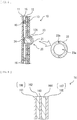
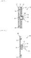
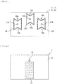
- FIG. 1 illustrates a side-face configuration example of the flat panel speaker 1 according to the present embodiment.
- FIG. 2 illustrates a rear-face configuration example of the flat panel speaker 1 in FIG. 1 .
- the flat panel speaker 1 also serves as a display unit that displays an image.
- the display unit includes the flat panel speaker 1 built therein, and is configured to be able to output sound from a display surface that displays an image.
- the flat panel speaker 1 includes, for example, a panel section 10 serving as a vibration plate, and a vibration section 20 disposed on a back surface of the panel section 10 and causing the panel section 10 to vibrate.
- the flat panel speaker 1 further includes, for example, a signal processor 30 that controls the vibration section 20, and a support section 40 that supports the panel section 10 through a rotation section 50.
- the rotation section 50 adjusts an inclination of the panel section 10 when the support section 40 supports the back surface of the panel section 10.
- the rotation section 50 is configured by, for example, a hinge that supports the panel section 10 and the support section 40 rotatably.
- the vibration section 20 and the signal processor 30 are disposed on the back surface of the panel section 10.
- the panel section 10 includes a back chassis 19 on back-surface side of the panel section 10, and the back chassis 19 protects the panel section 10, the vibration section 20, and the signal processor 30.
- the back chassis 19 is configured by, for example, a planar metal plate or resin plate.
- the back chassis 19 is coupled to the rotation section 50.
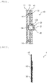
- FIG. 3 illustrates a configuration example of a rear face of the flat panel speaker 1 when the back chassis 19 is removed.
- FIG. 4 illustrates a cross-sectional configuration example taken along a line A-A in FIG. 3 .
- FIG. 5 illustrates a cross-sectional configuration example taken along a line B-B in FIG. 3 . It is to be noted that FIG. 5 illustrates an example of a cross-sectional configuration near a vibrator 21 (an actuator) described later, but this cross-sectional configuration is assumed to have a cross-sectional configuration similar to a cross-sectional configuration near another vibrator (e.g., a vibrator 22 (an actuator)).
- a vibrator 21 an actuator
- the panel section 10 includes, for example, a display cell 11 shaped like a thin plate to display an image, and an inner plate 12 (a facing plate) disposed to face the display cell 11 with a clearance 15 formed therebetween.
- a display cell 11 serving as the vibration plate for example, an edge of the display cell 11 may be round, and, for example, four corners of the display cell 11 may be round.
- the panel section 10 further includes, for example, a glass substrate 13 disposed in contact with a back surface of the inner plate 12, and a fixing member 14 disposed between the display cell 11 and the inner plate 12.
- the fixing member 14 serves to fix the display cell 11 and the inner plate 12 to each other, and serves as a spacer that maintains the clearance 15.
- the fixing member 14 is disposed, for example, along an outer edge of the display cell 11.
- the fixing member 14 may have, for example, flexibility to the extent that an end edge of the display cell 11 is allowed to serve as a free end when the display cell 11 vibrates.
- the fixing member 14 is configured by, for example, a buffer layer such as a sponge having a bonding layer on each of both sides.
- the inner plate 12 is a substrate that supports the vibrators 21 and 22 described later.
- the inner plate 12 has, for example, an opening at a location where each of the vibrators 21 and 22 is to be installed, and a protrusion 12A provided around the opening to support a fixing section 23 described later.
- the protrusion 12A protrudes on side opposite to the display cell 11.
- the glass substrate 13 has rigidity higher than that of the inner plate 12, and has a role in suppressing deflection or vibration of the inner plate 12.
- the glass substrate 13 has an opening at a position facing the protrusion 12A.
- the opening provided in the glass substrate 13 has a size that allows the protrusion 12A and the vibrator 21 or the vibrator 22 to be inserted therein.
- a resin substrate having rigidity equal to that of the glass substrate 13 may be provided.
- the vibration section 20 includes, for example, two vibrators (the vibrators 21 and 22).
- the vibrator 21 and the vibrator 22 have a common configuration.
- the vibrators 21 and 22 are disposed to avoid a location that most easily vibrates in the entire range of audio frequencies (e.g., 20 Hz to 20 kHz) when vibration is generated in the display cell 11 by the vibrators 21 and 22.
- Examples of the "location that most easily vibrates” include the location of anti-node of a largest stationary wave that occurs in the display cell 11, when vibration is generated in the display cell 11 by the vibrators 21 and 22.
- the vibrators 21 and 22 are disposed to avoid a location that least easily vibrates in the entire range of audio frequencies when vibration is generated in the display cell 11 by the vibrators 21 and 22.
- the vibration of the display cell 11 is determined by, for example, measuring vibration of the entire surface of the display cell 11 in the entire range of audio frequencies, using a laser Doppler vibrometer.
- the vibrators 21 and 22 are disposed, for example, at locations having an indivisible ratio, in a lateral direction and a vertical direction of the display cell 11. Examples of the "indivisible ratio" include 3:4, 5:7, 3:7, 2:5, and 7:11.
- the vibrator 21 is disposed on the left when the display cell 11 is viewed from a back surface.
- the vibrator 22 is disposed on the right when the display cell 11 is viewed from the back surface.
- the vibrators 21 and 22 each include, for example, a voice coil, a bobbin on which the voice coil is wound, and a magnetic circuit, and the vibrators 21 and 22 each serve as a speaker actuator to be a vibration source.
- the vibrators 21 and 22 each generate a driving force in the voice coil in accordance with the principle of electromagnetic action. This driving force is transmitted to the display cell 11 through a vibration transmission member 24 described later, and thereby generates vibration depending on a change in the sound current in the display cell 11. This causes air to vibrate, thereby changing a sound pressure.
- the vibration section 20 further includes, for example, the fixing section 23 and the vibration transmission member 24 for each of the vibrators (the vibrators 21 and 22).
- the fixing section 23 has, for example, an opening 23a provided to fix the vibrator 21 or the vibrator 22 in a state of being inserted therein.
- the fixing section 23 further has, for example, a plurality of screw holes 23b through each of which a screw is to be inserted, and the screw is used in fixing the fixing section 23 to the protrusion 12A.
- the vibrators (the vibrators 21 and 22) are each fixed to the inner plate 12 through the fixing section 23.
- the fixing section 23 may have, for example, a function as a heatsink that radiates heat generated from the vibrator 21 or the vibrator 22, besides fixing the vibrator 21 or the vibrator 22 to the inner plate 12.
- the vibration transmission member 24 is, for example, in contact with the back surface of the display cell 11 and with the bobbin of the vibrator 21 or the vibrator 22 of the display cell 11, and is fixed to the back surface of the display cell 11 and to the bobbin of the vibrator 21 or the vibrator 22.
- the vibration transmission member 24 is configured by a member at least having a characteristic of being resilient in a sound wave region (20 Hz or more).
- the vibration transmission member 24 is configured by, for example, thermosetting resin, double-sided tape, or low-resilience urethane, etc.
- the vibration transmission member 24 is configured by the thermosetting resin
- the vibration transmission member 24 is formed, for example, by generating heat in the voice coil through passage of an electric current to the voice coil, and curing the thermosetting resin with the heat.
- the vibration transmission member 24 is fixed to the back surface of the display cell 11 and to the bobbin of the vibrator 21 or the vibrator 22, for example, by inputting a constant pulse signal to the voice coil and pressing the double-sided tape hard with the voice coil.
- the vibration transmission member 24 is configured by the low-resilience urethane
- the low-resilience urethane has a characteristic of being resilient in the sound wave region (20 Hz or more) and has a characteristic of following in a low frequency region (less than 20 Hz). Hence, it is possible for the low-resilience urethane to follow displacement of the display cell 11 caused by shock from outside, without attenuating vibration of sound.
- the panel section 10 includes, for example, a vibration controlling member 16 as illustrated in FIG. 5 .
- the vibration controlling member 16 has a function of preventing a stationary wave caused by interference between vibration generated in the display cell 11 by the vibrator 21 and vibration generated in the display cell 11 by the vibrator 22.
- the vibration controlling member 16 may be configured by, for example, a material allowed to control reflection in the sound wave region (20 Hz or more) with respect to vibration generated by the vibrator 22. Further, the vibration controlling member 16 may be configured by, for example, a material allowed to absorb vibration or reverberation generated by the vibrator 22.
- the vibration controlling member 16 is disposed in a clearance between the display cell 11 and the inner plate 12, i.e., in a clearance 16.
- the vibration controlling member 16 is fixed at least to the back surface of the display cell 11, among the back surface of the display cell 11 and a surface of the inner plate 12.
- the vibration controlling member 16 is, for example, in contact with the surface of the inner plate 12.
- FIG. 6 illustrates a cross-sectional configuration example of the vibration controlling member 16.
- the vibration controlling member 16 is, for example, a stacked body in which a bonding layer 161 (or an adhesive layer 166), a sponge layer 162, a base material layer 163, a sponge layer 164, and a bonding layer 165 (or an adhesive layer 167) are stacked in this order from side of the display cell 11.
- the bonding layer 161 is in contact with the back surface of the display cell 11, and fixes the vibration controlling member 16 to the back surface of the display cell 11.
- the sponge layers 162 and 164 are layers that bring the above-described function.
- the sponge layers 162 and 164 are each configured by, for example, a flexible member that is poor in self-supporting.
- the vibration controlling member 16 includes a sponge as the flexible member that is poor in self-supporting, and further includes the adhesive layer 166 or the bonding layer 161 that fixes the sponge to the back surface of the display cell 11.
- the vibration controlling member 16 is not limited to the configuration illustrated in FIG. 6 .
- the vibration controlling member 16 may include, for example, an adhesive or a bond as the flexible member that is poor in self-supporting.
- the vibration controlling member 16 may have a configuration similar to that of the vibration transmission member 24 or the fixing section 23, for example.
- the vibration controlling member 16 may be, for example, a magnet sheet fixed to the display cell 11, or a hook-and-loop fastener fixed to the display cell 11 and the inner plate 12.
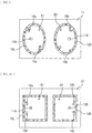
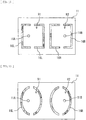
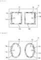
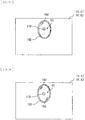
- FIG. 7 to FIG. 16 each illustrate a plane configuration example of the vibration controlling member 16.
- a position facing the vibrator 21 is a vibration point 11A (a first vibration point)
- a position facing the vibrator 22 is a vibration point 11B (a second vibration point).
- the vibration controlling member 16 partitions the back surface of the display cell 11 into a partition region R1 (a first partition region) including the vibration point 11A and a partition region R2 (a second partition region) including the vibration point 11B.
- the vibration controlling member 16 may include, for example, a vibration controlling member 16L (a first vibration controlling member) that forms the partition region R1, and a vibration controlling member 16R (a second vibration controlling member) that forms the partition region R2.
- the vibration controlling member 16L may include, for example, a plurality of protrusions 16a (first protrusions) protruding toward the vibration point 11A, as illustrated in FIG. 7 and FIG. 9 to FIG. 12 .
- the vibration controlling member 16R may include, for example, a plurality of protrusions 16b (second protrusions) protruding toward the vibration point 11B, as illustrated in FIG. 7 and FIG. 9 to FIG. 12 .
- the vibration controlling member 16L may include, for example, one protrusion 16a protruding toward the vibration point 11A, as illustrated in FIG. 8 .
- the vibration controlling member 16R may include, for example, one protrusion 16b protruding toward the vibration point 11B, as illustrated in FIG. 8 . From the viewpoint of suppression of a stationary wave, it is preferable that the vibration controlling member 16L include many protrusions 16a, and it is preferable that the vibration controlling member 16R include many protrusions 16a.
- the vibration controlling member 16L may be, for example, formed to have the partition region R1 being a closed region on the back surface of the display cell 11, as illustrated in FIG. 7 to FIG. 11 .
- the vibration controlling member 16R may be, for example, formed to have the partition region R2 being a closed region on the back surface of the display cell 11, as illustrated in FIG. 7 to FIG. 11 .
- the vibration controlling member 16L and the vibration controlling member 16R may be, for example, formed to have the partition region R1 and the partition region R2 communicating with each other and being a closed region on the back surface of the display cell 11, as illustrated in FIG. 12 .
- the vibration controlling member 16L may be, for example, shaped like a circular ring or a polygonal ring without having a location protruding toward the vibration point 11A, as illustrated in FIG. 13 and FIG. 14 .
- the vibration controlling member 16R may be, for example, shaped like a circular ring or a polygonal ring without having a location protruding toward the vibration point 11B, as illustrated in FIG. 13 and FIG. 14 .
- the vibration controlling member 16L may have, for example, a shape in which a ring-shaped protrusion is divided into two or more parts, as illustrated in FIG. 15 and FIG. 16 .
- the vibration controlling member 16R may have, for example, a shape in which a ring-shaped protrusion is divided into two or more parts, as illustrated in FIG. 15 and FIG. 16 .
- the vibration controlling member 16L may have, for example, an aspect ratio different from 1:1, as illustrated in FIG. 7 to FIG. 14 .
- the vibration controlling member 16R may have, for example, an aspect ratio different from 1:1, as illustrated in FIG. 7 to FIG. 14 .
- the vibration controlling member 16L is, for example, disposed near the left edge of the display cell 11 as illustrated in FIG. 10 , FIG. 17, and FIG. 18
- the vibration controlling member 16R is, for example, disposed near the right edge of the display cell 11, as illustrated in FIG. 10 , FIG. 17, and FIG. 18 .
- the plurality of protrusions 16a may be disposed near the left edge of the display cell 11 in the vibration controlling member 16L, and the plurality of protrusions 16b may be disposed near the right edge of the display cell 11 in the vibration controlling member 16R.
- the vibration controlling member 16L may be, for example, laterally symmetrical, when viewed from a central part of the display cell 11, as illustrated in FIG. 7 to FIG. 18 .
- the vibration controlling member 16R may be, for example, laterally symmetrical, when viewed from the central part of the display cell 11, as illustrated in FIG. 7 to FIG. 18 .
- the vibration controlling member 16L may be, for example, vertically symmetrical when viewed from the central part of the display cell 11, as illustrated in FIG. 7 , FIG.
- the vibration controlling member 16R may be, for example, vertically symmetrical when viewed from the central part of the display cell 11, as illustrated in FIG. 7 , FIG. 10 , and FIG. 13 to FIG. 18 .
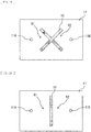
- the vibration controlling member 16 may be, for example, formed between the vibration point 11A and the vibration point 11B, as illustrated in FIG. 19 and FIG. 20 .
- the vibration controlling member 16 may be, for example, formed to have an X shape having a center disposed on a straight line connecting the vibration point 11A and the vibration point 11B, as illustrated in FIG. 19 .
- the vibration controlling member 16 may be, for example, formed to have an I shape having an extending direction intersecting (for example, orthogonal to) a straight line connecting the vibration point 11A and the vibration point 11B, as illustrated in FIG. 20 .
- the vibration controlling member 16L and the vibration controlling member 16R may have, for example, a laterally symmetrical shape, as illustrated in FIG. 7 to FIG. 14 . It is to be noted that the vibration controlling member 16 may be, for example, disposed away from the surface of the inner plate 12, as illustrated in FIG. 21 , insofar as the vibration controlling member 16 has the above-described function.
- Thickness and weight of displays have been rapidly reduced. Accordingly, thickness and weight of speakers have been also reduced, and use of a flat panel speaker (FPS) in place of or together with a cone-type speaker has been proposed.
- a range of uses of the flat panel speaker is expected to increase, and the flat panel speaker may be applied not only to a display, but also to a poster, etc. displayed at an exhibition, etc.
- the plurality of vibrators 21 and 22 are disposed on the back surface of the display cell 11, while avoiding a location that most easily vibrates in the entire range of audio frequencies when vibration is generated in the display cell 11 by the plurality of vibrators 21 and 22.
- a large stationary wave with respect to the display cell 11 therefore does not easily occur. As a result, it is possible to suppress a decline in sound quality.
- the plurality of vibrators 21 and 22 are disposed to avoid a location that least easily vibrates in the entire range of audio frequencies when vibration is generated in the display cell 11 by the plurality of vibrators 21 and 22. This makes it possible to generate vibration for the display cell 11.
- the back surface of the display cell 11 is partitioned by the vibration controlling member 16 fixed to the back surface of the display cell 11 into the partition region R1 including the vibration point 11A and the partition region R2 including the vibration point 11B.
- the vibration controlling member 16L is provided with the one or more protrusions 16a protruding toward the vibration point 11A
- the vibration controlling member 16R is provided with the one or more protrusions 16b protruding toward the vibration point 11B
- occurrence of a stationary wave is prevented by the one or more protrusions 16a and the one or more protrusions 16b.
- the vibration controlling member 16L in a case where the vibration controlling member 16L is formed to have the partition region R1 being a closed region on the back surface of the display cell 11, a stationary wave caused by vibration generated in the display cell 11 by the vibrator 21 is prevented. Furthermore, in the present embodiment, in a case where the vibration controlling member 16R is formed to have the partition region R2 being a closed region on the back surface of the display cell 11, a stationary wave caused by vibration generated in the display cell 11 by the vibrator 22 is prevented. Accordingly, in this case as well, it is possible to suppress a decline in sound quality.
- the vibration controlling member 16L and the vibration controlling member 16R are formed to have the partition region R1 and the partition region R2 communicating with each other and being a closed region on the back surface of the display cell 11, a stationary wave caused by vibration generated in the display cell 11 by the vibrator 21 is prevented and a stationary wave caused by vibration generated in the display cell 11 by the vibrator 22 is prevented. Accordingly, in this case as well, it is possible to suppress a decline in sound quality.
- the vibration controlling member 16L is shaped like a circular ring or a polygonal ring without having a location protruding toward the vibration point 11A
- a stationary wave caused by vibration generated in the display cell 11 by the vibrator 21 is prevented.
- the vibration controlling member 16R is shaped like a circular ring or a polygonal ring without having a location protruding toward the vibration point 11B
- a stationary wave caused by vibration generated in the display cell 11 by the vibrator 22 is prevented. Accordingly, in this case as well, it is possible to suppress a decline in sound quality.
- the vibration controlling member 16L is disposed near the left edge of the display cell 11
- the vibration controlling member 16R is disposed near the right edge of the display cell 11
- the plurality of protrusions 16a are disposed near the left edge of a flat panel 11 in the vibration controlling member 16L
- the plurality of protrusions 16b are disposed near the right edge of the flat panel 11 in the vibration controlling member 16R
- the aspect ratio of the vibration controlling member 16L is different from 1:1, and further the aspect ratio of the vibration controlling member 16R is different from 1:1, a large stationary wave with respect to the display cell 11 does not easily occur. As a result, it is possible to suppress a decline in sound quality.
- the vibration controlling members 16L and 16R each have a shape in which the ring-shaped protrusion is divided into two or more parts, it is possible to allow a stationary wave to escape from a clearance formed in each of the vibration controlling members 16L and 16R. A large stationary wave with respect to the display cell 11 therefore does not easily occur. As a result, it is possible to suppress a decline in sound quality.
- each of the vibration controlling members 16L and 16R is laterally symmetrical and vertically symmetrical, when viewed from the middle part of the flat panel 11, it is possible to equate a characteristic of sound generated by the vibrator 21 and a characteristic of sound generated by the vibrator 22 with each other. As a result, it is possible to enhance the sound quality.
- the vibration controlling member 16 in a case where the vibration controlling member 16 is configured by a flexible member that is poor in self-supporting, reflection of a sound wave in the vibration controlling member 16 weakens. This brings in-plane distribution of the stationary wave closer to being flat, thereby making it possible to suppress a decline in sound quality.
- the vibration controlling member 16 also in a case where the vibration controlling member 16 includes a sponge as the flexible member that is poor in self-supporting and further includes an adhesive layer 16f or a bonding layer 16a that fixes the sponge to the back surface of the display cell 11, the reflection of the sound wave in the vibration controlling member 16 weakens. This brings the in-plane distribution of the stationary wave closer to being flat, thereby making it possible to suppress a decline in sound quality.
- the vibration controlling member 16 includes an adhesive or a bond as the flexible member that is poor in self-supporting
- the reflection of the sound wave in the vibration controlling member 16 weakens. This brings the in-plane distribution of the stationary wave closer to being flat, thereby making it possible to suppress a decline in sound quality.
- the vibrators in a case where the vibrators (the vibrators 21 and 22) are each fixed to the inner plate 12 disposed to face the display cell 11 with a predetermined clearance formed therebetween, it is possible to transmit vibration of each of the vibrators (the vibrators 21 and 22) to the display cell 11 efficiently. Hence, it is possible to suppress a decline in sound quality.
- the vibration controlling member 16 in a case where the vibration controlling member 16 is in contact with the inner plate 12, it is possible to further increase the function of vibration control by the vibration controlling member 16. Hence, it is possible to suppress a decline in sound quality. It is to be noted that, in the present embodiment, in a case where the vibration controlling member 16 is disposed away from the inner plate 12, it is possible to expect a vibration-control effect by a self-weight.
- the support section 40 and the rotation section 50 may be omitted as illustrated in FIG. 22 and FIG. 23 .
- the back chassis 19 is provided with a recess 32 to be used for hanging the flat panel speaker 1 on a hook provided on a wall, etc. It is to be noted that in a case where a flat panel speaker 2 is placed on a table top stand, the above-described recess 32 may be absent.
- FIG. 24 illustrates a side-face configuration example of the flat panel speaker 2 according to the present embodiment.
- FIG. 25 illustrates a rear-face configuration example of the flat panel speaker 2 in FIG. 24 .
- the flat panel speaker 2 also serves as a display unit that displays an image.
- the display unit includes the flat panel speaker 2 built therein, and is configured to be able to output sound from a display surface that displays an image.
- the flat panel speaker 2 includes, for example, a panel section 60 serving as a vibration plate, and a vibration section 70 disposed on a back surface of the panel section 60 and causing the panel section 60 to vibrate.
- the flat panel speaker 2 further includes, for example, a support section 80 in which a signal processing circuit 81 that controls the vibration section 70 is built.
- the support section 80 is fixed to a back chassis 69 through a rotation section 90.
- the rotation section 90 adjusts an inclination of the panel section 60 when the support section 80 supports the back surface of the panel section 60.
- the rotation section 90 is configured by, for example, a hinge that supports the panel section 60 and the support section 80 rotatably.
- FIG. 26 illustrates a configuration example of a rear face of the flat panel speaker 2 when the back chassis 69 is removed.
- FIG. 27 illustrates a cross-sectional configuration example taken along a line A-A in FIG. 26 .
- the panel section 60 includes, for example, a display cell 61 shaped like a thin plate to display an image, and the vibration controlling member 16 fixed to a back surface of the display cell 61.
- the vibration controlling member 16 has a function of preventing a stationary wave caused by interference between vibration generated in the display cell 61 by the vibrator 21 and vibration generated in the display cell 61 by the vibrator 22.
- the vibration controlling member 16 has a configuration similar to that in the foregoing embodiment.
- the vibration section 70 includes, for example, two vibrators (the vibrators 21 and 22), as with the foregoing embodiment.
- the vibrator 21 is disposed on the left, when the display cell 61 is viewed from the back surface.
- the vibrator 22 is disposed on the right, when the display cell 61 is viewed from the back surface.
- the vibration section 70 further includes a wiring board 71 that electrically couples the signal processing circuit 81 and the two vibrators (the vibrators 21 and 22) together.
- a flexible wiring board is coupled to the wiring board 71, and the two vibrators (the vibrators 21 and 22) and the signal processing circuit 81 are electrically coupled through this flexible wiring board.
- the vibration section 70 further includes, for example, a fixing section 72, a fixing member 73, and the vibration transmission member 24, for each of the vibrators.
- the fixing section 72 has, for example, an opening 72a provided to fix the vibrator 21 or the vibrator 22 in a state of being inserted therein.
- the vibrators are each fixed to the back surface of the display cell 61 through the fixing section 72 and the fixing member 73.
- the vibrators (the vibrators 21 and 22) are each fixed at a position different from a position facing the vibrators (the vibrators 21 and 22) by the fixing member 73, with respect to the back surface of the display cell 61.
- a fixing section 73 may serve, for example, as a heatsink that radiates heat generated from the vibrator 21 or the vibrator 22, besides fixing the vibrator 21 or the vibrator 22 to the back surface of the display cell 61.
- the fixing member 73 serves to fix the display cell 61 and the fixing section 72 to each other.
- the fixing member 73 may have, for example, flexibility to the extent of avoiding attenuation of vibration of the display cell 61 when the display cell 61 vibrates.
- the fixing member 73 is configured by, for example, a sponge having a bonding layer on each of both sides.
- the back surface of the display cell 61 is partitioned by the vibration controlling member 16 fixed to the back surface of the display cell 61 into the partition region R1 including the vibration point 11A and the partition region R2 including the vibration point 11B.
- the vibration controlling member 16 in the present embodiment has effects similar to the effects obtained by the vibration controlling member 16 in the foregoing embodiment.
- the vibrators are each fixed at the position different from the position facing the vibrators (the vibrators 21 and 22), with respect to the back surface of the display cell 61.
- the vibrators each therefore vibrate together with the display cell 61, and thus, amplitude attributable to resonance increases, which makes it possible to increase an output in a low frequency region.
- a flat panel 17 or a flat panel 63 having no display function may be provided in place of the display cell 11 or the display cell 61, as illustrated in FIG. 28 , FIG. 29, and FIG. 30 .
- FIG. 28 , FIG. 29, and FIG. 30 it is possible to obtain effects similar to the effects in each of the foregoing embodiments and modification examples thereof.
- the number of vibrators may be three or more.
- a vibrator 20 may include three vibrators (the vibrators 21 and 22, as well as a vibrator 25), for example, as illustrated in FIG. 31 .
- a vibrator 70 may include three vibrators (the vibrators 21, 22, and 25) in the above-described second embodiment and the modification example thereof, for example, as illustrated in FIG. 32 .
- the third vibrator (the vibrator 25) is positioned, for example, between the vibrator 21 and the vibrator 22, as illustrated in FIG. 31 and FIG. 32 .
- the vibrator 25 (the actuator) has a configuration similar to that of the vibrator 21.
- FIG. 33 illustrates a rear-face configuration example of the vibration controlling member 16 in the present modification example.
- the vibration controlling member 16D partitions the back surface of the display cell 11, the display cell 61, the flat panel 17, or the flat panel 63 into a partition region R3 including the vibration point 11D, and is fixed to the back surface of the display cell 11, the display cell 61, the flat panel 17, or the flat panel 63.
- the vibration controlling member 16D has a configuration similar to that of the vibration controlling member 16L or the vibration controlling member 16R.
- the number of vibrators may be one.
- the vibrator 20 or the vibrator 70 may include one vibrator (the vibrator 25), for example, as illustrated in FIG. 34 and FIG. 35 .
- the vibrator 25 is disposed to avoid a location that most easily vibrates in the entire range of audio frequencies when vibration is generated in the display cell 11, the display cell 61, the flat panel 17, or the flat panel 63 by the vibrator 25.
- the vibrator 25 is disposed to avoid a location that least easily vibrates in the entire range of audio frequencies when vibration is generated in the display cell 11, the display cell 61, the flat panel 17, or the flat panel 63 by the vibrator 25.
- the vibration of the display cell 11, the display cell 61, the flat panel 17, or the flat panel 63 is determined by, for example, measuring vibration of the entire surface of the display cell 11, the display cell 61, the flat panel 17, or the flat panel 63 in the entire range of audio frequencies, by using a laser Doppler vibrometer.
- the vibrator 25 is disposed at locations having an indivisible ratio, in the lateral direction and the vertical direction of the display cell 11, the display cell 61, the flat panel 17, or the flat panel 63. Examples of the "indivisible ratio" include 3:4, 5:7, 3:7, 2:5, and 7:11.
- the vibration controlling member 16D partitions the back surface of the display cell 11, the display cell 61, the flat panel 17, or the flat panel 63 into the partition region R3 including the vibration point 11D, and is fixed to the back surface of the display cell 11, the display cell 61, the flat panel 17, or the flat panel 63.
- the vibration controlling member 16D has a function of preventing a stationary wave caused by vibration generated in the display cell 11, the display cell 61, the flat panel 17, or the flat panel 63 by the vibrator 25.
- the vibration controlling member 16D may be configured by, for example, a material allowed to control reflection in the sound wave region (20 Hz or more) with respect to the vibration generated by the vibrator 25. Further, the vibration controlling member 16D may be configured by, for example, a material allowed to absorb vibration or reverberation generated by the vibrator 25.
- the vibration controlling member 16D may include, for example, a plurality of protrusions 16d (third protrusions) protruding toward the vibration point 11D, as illustrated in FIG. 36 and FIG. 38 to FIG. 40 .
- the vibration controlling member 16D may include, for example, one protrusion 16d protruding toward the vibration point 11D, as illustrated in FIG. 37 .
- the vibration controlling member 16D may be, for example, formed to have the partition region R3 being a closed region on the back surface of the display cell 11, the display cell 61, the flat panel 17, or the flat panel 63, as illustrated in FIG. 36 to FIG. 42 .
- the vibration controlling member 16D may be, for example, shaped like a circular ring or a polygonal ring without having a location protruding toward the vibration point 11D, as illustrated in FIG. 41 and FIG. 42 . It is to be noted that the vibration controlling member 16D may be disposed away from the surface of the inner plate 12, insofar as the vibration controlling member 16D has a function similar to the function of the vibration controlling member 16.
- the back surface of the display cell 11, the display cell 61, the flat panel 17, or the flat panel 63 is partitioned by the vibration controlling member 16D fixed to the back surface of the display cell 11, the display cell 61, the flat panel 17, or the flat panel 63, into the partition region R3 including the vibration point 11D.
- the vibration controlling member 16D in the present modification example has effects similar to the effects obtained by the vibration controlling member 16 in the foregoing embodiments.
- the vibration controlling member 16D may be formed on substantially the entire back surface of the display cell 61, the flat panel 17, or the flat panel 63.
- the vibration controlling member 16D may be formed in a wide range of the back surface of the display cell 61, the flat panel 17, or the flat panel 63.
Landscapes
- Engineering & Computer Science (AREA)
- Physics & Mathematics (AREA)
- Acoustics & Sound (AREA)
- Signal Processing (AREA)
- Multimedia (AREA)
- Diaphragms For Electromechanical Transducers (AREA)
- Details Of Audible-Bandwidth Transducers (AREA)
- Audible-Bandwidth Dynamoelectric Transducers Other Than Pickups (AREA)
Description
- The disclosure relates to a flat panel speaker and a display unit.
- Thickness and weight of displays have been rapidly reduced. Accordingly, thickness and weight of speakers have been also reduced, and use of a flat panel speaker (FPS) in place of or together with a cone-type speaker has been proposed. A range of uses of the flat panel speaker is expected to increase, and the flat panel speaker may be applied not only to a display, but also to a poster, etc. displayed at an exhibition, etc. For example,
PTL 1 to PTL 3 each disclose a flat panel speaker. -
EP 0847661 discloses that a panel-form loudspeaker comprises a rectangular frame carrying a resilient suspension around its inner periphery which supports a distributed mode sound radiating panel. A transducer is mounted wholly and exclusively on or in the panel at a predetermined location.EP 0847661 discloses that the transducer serves to launch or excite bending waves in the panel to cause the panel to resonate and radiate an acoustic output. -
EP 2884765 discloses acoustic generators generating sounds by applying a voltage to an actuator mounted on a vibrating plate. The acoustic generator includes aframe 2, a vibrating plate 3, and a piezoelectric element 5.EP 2884765 discloses that the acoustic generator has at least one pair of two adjacent portions with different stiffness, and is provided with at least onedamper 8 that is positioned contacting with both of the two adjacent portions with different stiffness. -
US 2016/337758 discloses an acoustic generator.US 2016/337758 discloses that an acoustic generator includes a vibration body, a first exciter and a second exciter which are disposed on the vibration body, a first damping material disposed on the vibration body and having a first portion which overlaps the first exciter, and a second damping material disposed on the vibration body and having a second portion which overlaps the second exciter. -
- PTL 1: Japanese Unexamined Patent Application Publication No.
2007-143010 - PTL 2: Japanese Unexamined Patent Application Publication No.
2009-159104 - PTL 3: Japanese Unexamined Patent Application Publication (Published Japanese Translation of PCT Application) No.
2002-510182 - However, in a typical flat panel speaker, there are cases where sound quality declines, such as a case where glare occurs in sound, and a case where sound of a specific frequency band is not easily emitted, due to an influence of a stationary wave that occurs in a vibration plate. It is therefore desirable to provide a flat panel speaker and a display unit that make it possible to suppress a decline in sound quality.
- A first flat panel speaker according to an embodiment of the disclosure includes a flat panel, and a plurality of vibrators that are disposed on a back surface of the flat panel and cause the flat panel to vibrate. The plurality of vibrators are disposed to avoid a location that most easily vibrates in an entire range of audio frequencies when vibration is generated in the flat panel by the plurality of vibrators.
- A first display unit according to an embodiment of the disclosure includes a display cell that is shaped like a thin plate and displays an image, and a plurality of vibrators that are disposed on a back surface of the display cell and cause the display cell to vibrate. The plurality of vibrators are disposed to avoid a location that most easily vibrates in an entire range of audio frequencies when vibration is generated in the display cell by the plurality of vibrators.
- In the first flat panel speaker and the first display unit according to the respective embodiments of the disclosure, the plurality of vibrators disposed on the back surface of the flat panel or the display cell are disposed to avoid the location that most easily vibrates in the entire range of audio frequencies when vibration is generated in the flat panel or the display cell by the plurality of vibrators. A large stationary wave with respect to the flat panel or the display cell therefore does not easily occur.
- A second flat panel speaker according to an embodiment of the disclosure includes a flat panel, and a vibrator that is disposed on a back surface of the flat panel and causes the flat panel to vibrate. The vibrator is disposed to avoid a location that most easily vibrates in an entire range of audio frequencies when vibration is generated in the flat panel by the vibrator.
- A second display unit according to an embodiment of the disclosure includes a display cell that is shaped like a thin plate and displays an image, and a vibrator that is disposed on a back surface of the display cell and causes the display cell to vibrate. The vibrator is disposed to avoid a location that most easily vibrates in an entire range of audio frequencies when vibration is generated in the flat panel by the vibrator.
- In the second flat panel speaker and the second display unit according to the respective embodiments of the disclosure, the plurality of vibrators disposed on the back surface of the flat panel or the display cell are disposed to avoid the location that most easily vibrates in the entire range of audio frequencies when vibration is generated in the flat panel or the display cell by the plurality of vibrators. A large stationary wave with respect to the flat panel or the display cell therefore does not easily occur.
- According to the first flat panel speaker and the first display unit of the respective embodiments of the disclosure, a large stationary wave with respect to the flat panel or the display cell does not easily occur, thus making it possible to suppress a decline in sound quality.
- According to the second flat panel speaker and the second display unit of the respective embodiments of the disclosure, a large stationary wave with respect to the flat panel or the display cell does not easily occur, thus making it possible to suppress a decline in sound quality.
- It is to be noted that effects of the technology are not necessarily limited to the effects described here, and may be any of effects described therein.
-
- [
FIG. 1] FIG. 1 illustrates a side-face configuration example of a flat panel speaker according to a first embodiment of the disclosure. - [
FIG. 2] FIG. 2 illustrates a rear-face configuration example of the flat panel speaker inFIG. 1 . - [
FIG. 3] FIG. 3 illustrates a configuration example of a rear face of the flat panel speaker when a back chassis inFIG. 2 is removed. - [
FIG. 4] FIG. 4 illustrates a cross-sectional configuration example taken along a line A-A inFIG. 3 . - [
FIG. 5] FIG. 5 illustrates a cross-sectional configuration example taken along a line B-B inFIG. 3 . - [
FIG. 6] FIG. 6 illustrates a cross-sectional configuration example of a vibration controlling member inFIG. 4 . - [
FIG. 7] FIG. 7 illustrates a plane configuration example of the vibration controlling member inFIG. 4 . - [
FIG. 8] FIG. 8 illustrates a plane configuration example of the vibration controlling member inFIG. 4 . - [
FIG. 9] FIG. 9 illustrates a plane configuration example of the vibration controlling member inFIG. 4 . - [
FIG. 10] FIG. 10 illustrates a plane configuration example of the vibration controlling member inFIG. 4 . - [
FIG. 11] FIG. 11 illustrates a plane configuration example of the vibration controlling member inFIG. 4 . - [
FIG. 12] FIG. 12 illustrates a plane configuration example of the vibration controlling member inFIG. 4 . - [
FIG. 13] FIG. 13 illustrates a plane configuration example of the vibration controlling member inFIG. 4 . - [
FIG. 14] FIG. 14 illustrates a plane configuration example of the vibration controlling member inFIG. 4 . - [
FIG. 15] FIG. 15 illustrates a plane configuration example of the vibration controlling member inFIG. 4 . - [
FIG. 16] FIG. 16 illustrates a plane configuration example of the vibration controlling member inFIG. 4 . - [
FIG. 17] FIG. 17 illustrates a plane configuration example of the vibration controlling member inFIG. 4 . - [
FIG. 18] FIG. 18 illustrates a plane configuration example of the vibration controlling member inFIG. 4 . - [
FIG. 19] FIG. 19 illustrates a plane configuration example of the vibration controlling member inFIG. 4 . - [
FIG. 20] FIG. 20 illustrates a plane configuration example of the vibration controlling member inFIG. 4 . - [
FIG. 21] FIG. 21 illustrates a modification example of the cross-sectional configuration inFIG. 5 . - [
FIG. 22] FIG. 22 illustrates a modification example of the side-face configuration of the panel speaker inFIG. 1 . - [
FIG. 23] FIG. 23 illustrates a rear-face configuration example of the flat panel speaker inFIG. 22 . - [
FIG. 24] FIG. 24 illustrates a side-face configuration example of a flat panel speaker according to a second embodiment of the disclosure. - [
FIG. 25] FIG. 25 illustrates a rear-face configuration example of the flat panel speaker inFIG. 24 . - [
FIG. 26] FIG. 26 illustrates a configuration example of a rear face of the flat panel speaker when a back chassis inFIG. 25 is removed. - [
FIG. 27] FIG. 27 illustrates a cross-sectional configuration example taken along a line A-A inFIG. 26 . - [
FIG. 28] FIG. 28 illustrates a modification example of the cross-sectional configuration inFIG. 5 . - [
FIG. 29] FIG. 29 illustrates a modification example of the cross-sectional configuration inFIG. 21 . - [
FIG. 30] FIG. 30 illustrates a modification example of the cross-sectional configuration inFIG. 27 . - [
FIG. 31] FIG. 31 illustrates a modification example of the rear-face configuration inFIG. 3 . - [
FIG. 32] FIG. 32 illustrates a modification example of a rear-face configuration inFIG. 27 . - [
FIG. 33] FIG. 33 illustrates a modification example of a rear-face configuration inFIG. 7 . - [
FIG. 34] FIG. 34 illustrates a modification example of the rear-face configuration inFIG. 31 . - [
FIG. 35] FIG. 35 illustrates a modification example of the rear-face configuration inFIG. 32 . - [
FIG. 36] FIG. 36 illustrates a modification example of the rear-face configuration inFIG. 33 . - [
FIG. 37] FIG. 37 illustrates a modification example of the rear-face configuration inFIG. 36 . - [
FIG. 38] FIG. 38 illustrates a modification example of the rear-face configuration inFIG. 36 . - [
FIG. 39] FIG. 39 illustrates a modification example of the rear-face configuration inFIG. 36 . - [
FIG. 40] FIG. 40 illustrates a modification example of the rear-face configuration inFIG. 36 . - [
FIG. 41] FIG. 41 illustrates a modification example of the rear-face configuration inFIG. 36 . - [
FIG. 42] FIG. 42 illustrates a modification example of the rear-face configuration inFIG. 36 . - [
FIG. 43] FIG. 43 illustrates a modification example of the rear-face configuration inFIG. 36 . - Some embodiments of the disclosure are described below in detail with reference to the drawings. The following description is a specific example of the disclosure, and the disclosure is not limited to the following implementation.
- A
flat panel speaker 1 according to a first embodiment of the disclosure is described.FIG. 1 illustrates a side-face configuration example of theflat panel speaker 1 according to the present embodiment.FIG. 2 illustrates a rear-face configuration example of theflat panel speaker 1 inFIG. 1 . Theflat panel speaker 1 also serves as a display unit that displays an image. In other words, it may be said that the display unit includes theflat panel speaker 1 built therein, and is configured to be able to output sound from a display surface that displays an image. - The
flat panel speaker 1 includes, for example, apanel section 10 serving as a vibration plate, and avibration section 20 disposed on a back surface of thepanel section 10 and causing thepanel section 10 to vibrate. Theflat panel speaker 1 further includes, for example, asignal processor 30 that controls thevibration section 20, and asupport section 40 that supports thepanel section 10 through arotation section 50. Therotation section 50 adjusts an inclination of thepanel section 10 when thesupport section 40 supports the back surface of thepanel section 10. Therotation section 50 is configured by, for example, a hinge that supports thepanel section 10 and thesupport section 40 rotatably. - The
vibration section 20 and thesignal processor 30 are disposed on the back surface of thepanel section 10. Thepanel section 10 includes aback chassis 19 on back-surface side of thepanel section 10, and theback chassis 19 protects thepanel section 10, thevibration section 20, and thesignal processor 30. Theback chassis 19 is configured by, for example, a planar metal plate or resin plate. Theback chassis 19 is coupled to therotation section 50. -
FIG. 3 illustrates a configuration example of a rear face of theflat panel speaker 1 when theback chassis 19 is removed.FIG. 4 illustrates a cross-sectional configuration example taken along a line A-A inFIG. 3 .FIG. 5 illustrates a cross-sectional configuration example taken along a line B-B inFIG. 3 . It is to be noted thatFIG. 5 illustrates an example of a cross-sectional configuration near a vibrator 21 (an actuator) described later, but this cross-sectional configuration is assumed to have a cross-sectional configuration similar to a cross-sectional configuration near another vibrator (e.g., a vibrator 22 (an actuator)). - The
panel section 10 includes, for example, adisplay cell 11 shaped like a thin plate to display an image, and an inner plate 12 (a facing plate) disposed to face thedisplay cell 11 with aclearance 15 formed therebetween. In thedisplay cell 11 serving as the vibration plate, for example, an edge of thedisplay cell 11 may be round, and, for example, four corners of thedisplay cell 11 may be round. Thepanel section 10 further includes, for example, aglass substrate 13 disposed in contact with a back surface of theinner plate 12, and a fixingmember 14 disposed between thedisplay cell 11 and theinner plate 12. - The fixing
member 14 serves to fix thedisplay cell 11 and theinner plate 12 to each other, and serves as a spacer that maintains theclearance 15. The fixingmember 14 is disposed, for example, along an outer edge of thedisplay cell 11. The fixingmember 14 may have, for example, flexibility to the extent that an end edge of thedisplay cell 11 is allowed to serve as a free end when thedisplay cell 11 vibrates. The fixingmember 14 is configured by, for example, a buffer layer such as a sponge having a bonding layer on each of both sides. - The
inner plate 12 is a substrate that supports thevibrators inner plate 12 has, for example, an opening at a location where each of thevibrators protrusion 12A provided around the opening to support a fixingsection 23 described later. Theprotrusion 12A protrudes on side opposite to thedisplay cell 11. Theglass substrate 13 has rigidity higher than that of theinner plate 12, and has a role in suppressing deflection or vibration of theinner plate 12. Theglass substrate 13 has an opening at a position facing theprotrusion 12A. The opening provided in theglass substrate 13 has a size that allows theprotrusion 12A and thevibrator 21 or thevibrator 22 to be inserted therein. In place of theglass substrate 13, a resin substrate having rigidity equal to that of theglass substrate 13 may be provided. - The
vibration section 20 includes, for example, two vibrators (thevibrators 21 and 22). Thevibrator 21 and thevibrator 22 have a common configuration. Thevibrators display cell 11 by thevibrators display cell 11, when vibration is generated in thedisplay cell 11 by thevibrators vibrators display cell 11 by thevibrators display cell 11 is determined by, for example, measuring vibration of the entire surface of thedisplay cell 11 in the entire range of audio frequencies, using a laser Doppler vibrometer. Thevibrators display cell 11. Examples of the "indivisible ratio" include 3:4, 5:7, 3:7, 2:5, and 7:11. - The
vibrator 21 is disposed on the left when thedisplay cell 11 is viewed from a back surface. Thevibrator 22 is disposed on the right when thedisplay cell 11 is viewed from the back surface. Thevibrators vibrators vibrators display cell 11 through avibration transmission member 24 described later, and thereby generates vibration depending on a change in the sound current in thedisplay cell 11. This causes air to vibrate, thereby changing a sound pressure. - The
vibration section 20 further includes, for example, the fixingsection 23 and thevibration transmission member 24 for each of the vibrators (thevibrators 21 and 22). - The fixing
section 23 has, for example, anopening 23a provided to fix thevibrator 21 or thevibrator 22 in a state of being inserted therein. The fixingsection 23 further has, for example, a plurality of screw holes 23b through each of which a screw is to be inserted, and the screw is used in fixing the fixingsection 23 to theprotrusion 12A. For example, the vibrators (thevibrators 21 and 22) are each fixed to theinner plate 12 through the fixingsection 23. The fixingsection 23 may have, for example, a function as a heatsink that radiates heat generated from thevibrator 21 or thevibrator 22, besides fixing thevibrator 21 or thevibrator 22 to theinner plate 12. - The
vibration transmission member 24 is, for example, in contact with the back surface of thedisplay cell 11 and with the bobbin of thevibrator 21 or thevibrator 22 of thedisplay cell 11, and is fixed to the back surface of thedisplay cell 11 and to the bobbin of thevibrator 21 or thevibrator 22. Thevibration transmission member 24 is configured by a member at least having a characteristic of being resilient in a sound wave region (20 Hz or more). Thevibration transmission member 24 is configured by, for example, thermosetting resin, double-sided tape, or low-resilience urethane, etc. In a case where thevibration transmission member 24 is configured by the thermosetting resin, thevibration transmission member 24 is formed, for example, by generating heat in the voice coil through passage of an electric current to the voice coil, and curing the thermosetting resin with the heat. In a case where thevibration transmission member 24 is configured by the double-sided tape, thevibration transmission member 24 is fixed to the back surface of thedisplay cell 11 and to the bobbin of thevibrator 21 or thevibrator 22, for example, by inputting a constant pulse signal to the voice coil and pressing the double-sided tape hard with the voice coil. In a case where thevibration transmission member 24 is configured by the low-resilience urethane, it is preferable that the low-resilience urethane has a characteristic of being resilient in the sound wave region (20 Hz or more) and has a characteristic of following in a low frequency region (less than 20 Hz). Hence, it is possible for the low-resilience urethane to follow displacement of thedisplay cell 11 caused by shock from outside, without attenuating vibration of sound. - Incidentally, the
panel section 10 includes, for example, avibration controlling member 16 as illustrated inFIG. 5 . Thevibration controlling member 16 has a function of preventing a stationary wave caused by interference between vibration generated in thedisplay cell 11 by thevibrator 21 and vibration generated in thedisplay cell 11 by thevibrator 22. Thevibration controlling member 16 may be configured by, for example, a material allowed to control reflection in the sound wave region (20 Hz or more) with respect to vibration generated by thevibrator 22. Further, thevibration controlling member 16 may be configured by, for example, a material allowed to absorb vibration or reverberation generated by thevibrator 22. Thevibration controlling member 16 is disposed in a clearance between thedisplay cell 11 and theinner plate 12, i.e., in aclearance 16. Thevibration controlling member 16 is fixed at least to the back surface of thedisplay cell 11, among the back surface of thedisplay cell 11 and a surface of theinner plate 12. Thevibration controlling member 16 is, for example, in contact with the surface of theinner plate 12. -
FIG. 6 illustrates a cross-sectional configuration example of thevibration controlling member 16. Thevibration controlling member 16 is, for example, a stacked body in which a bonding layer 161 (or an adhesive layer 166), asponge layer 162, abase material layer 163, asponge layer 164, and a bonding layer 165 (or an adhesive layer 167) are stacked in this order from side of thedisplay cell 11. Thebonding layer 161 is in contact with the back surface of thedisplay cell 11, and fixes thevibration controlling member 16 to the back surface of thedisplay cell 11. The sponge layers 162 and 164 are layers that bring the above-described function. The sponge layers 162 and 164 are each configured by, for example, a flexible member that is poor in self-supporting. At this time, thevibration controlling member 16 includes a sponge as the flexible member that is poor in self-supporting, and further includes theadhesive layer 166 or thebonding layer 161 that fixes the sponge to the back surface of thedisplay cell 11. - In a case where the sponge layers 162 and 164 each have high hardness, reflection of a sound wave at the sponge layers 162 and 164 is strong. Hence, in-plane distribution of a stationary wave is not flat, but a sound pressure tends to rise. In a case where the sponge layers 162 and 164 each have low hardness, the reflection of the sound wave at the sponge layers 162 and 164 weakens. Hence, the in-plane distribution of the stationary wave comes closer to being flat, but the sound pressure tends to fall.
- It is to be noted that insofar as the
vibration controlling member 16 has the above-described function, thevibration controlling member 16 is not limited to the configuration illustrated inFIG. 6 . Thevibration controlling member 16 may include, for example, an adhesive or a bond as the flexible member that is poor in self-supporting. Thevibration controlling member 16 may have a configuration similar to that of thevibration transmission member 24 or the fixingsection 23, for example. Thevibration controlling member 16 may be, for example, a magnet sheet fixed to thedisplay cell 11, or a hook-and-loop fastener fixed to thedisplay cell 11 and theinner plate 12. -
FIG. 7 to FIG. 16 each illustrate a plane configuration example of thevibration controlling member 16. Here, assume that on the back surface of thedisplay cell 11, a position facing the vibrator 21 (a first vibrator) is avibration point 11A (a first vibration point), and a position facing the vibrator 22 (a second vibrator) is avibration point 11B (a second vibration point). In this situation, thevibration controlling member 16 partitions the back surface of thedisplay cell 11 into a partition region R1 (a first partition region) including thevibration point 11A and a partition region R2 (a second partition region) including thevibration point 11B. Thevibration controlling member 16 may include, for example, avibration controlling member 16L (a first vibration controlling member) that forms the partition region R1, and avibration controlling member 16R (a second vibration controlling member) that forms the partition region R2. - The
vibration controlling member 16L may include, for example, a plurality ofprotrusions 16a (first protrusions) protruding toward thevibration point 11A, as illustrated inFIG. 7 andFIG. 9 toFIG. 12 . Thevibration controlling member 16R may include, for example, a plurality ofprotrusions 16b (second protrusions) protruding toward thevibration point 11B, as illustrated inFIG. 7 andFIG. 9 toFIG. 12 . Thevibration controlling member 16L may include, for example, oneprotrusion 16a protruding toward thevibration point 11A, as illustrated inFIG. 8 . Thevibration controlling member 16R may include, for example, oneprotrusion 16b protruding toward thevibration point 11B, as illustrated inFIG. 8 . From the viewpoint of suppression of a stationary wave, it is preferable that thevibration controlling member 16L includemany protrusions 16a, and it is preferable that thevibration controlling member 16R includemany protrusions 16a. - The
vibration controlling member 16L may be, for example, formed to have the partition region R1 being a closed region on the back surface of thedisplay cell 11, as illustrated inFIG. 7 to FIG. 11 . Thevibration controlling member 16R may be, for example, formed to have the partition region R2 being a closed region on the back surface of thedisplay cell 11, as illustrated inFIG. 7 to FIG. 11 . Thevibration controlling member 16L and thevibration controlling member 16R may be, for example, formed to have the partition region R1 and the partition region R2 communicating with each other and being a closed region on the back surface of thedisplay cell 11, as illustrated inFIG. 12 . - The
vibration controlling member 16L may be, for example, shaped like a circular ring or a polygonal ring without having a location protruding toward thevibration point 11A, as illustrated inFIG. 13 and FIG. 14 . Thevibration controlling member 16R may be, for example, shaped like a circular ring or a polygonal ring without having a location protruding toward thevibration point 11B, as illustrated inFIG. 13 and FIG. 14 . Thevibration controlling member 16L may have, for example, a shape in which a ring-shaped protrusion is divided into two or more parts, as illustrated inFIG. 15 and FIG. 16 . Thevibration controlling member 16R may have, for example, a shape in which a ring-shaped protrusion is divided into two or more parts, as illustrated inFIG. 15 and FIG. 16 . Thevibration controlling member 16L may have, for example, an aspect ratio different from 1:1, as illustrated inFIG. 7 to FIG. 14 . Thevibration controlling member 16R may have, for example, an aspect ratio different from 1:1, as illustrated inFIG. 7 to FIG. 14 . Thevibration controlling member 16L is, for example, disposed near the left edge of thedisplay cell 11 as illustrated inFIG. 10 ,FIG. 17, and FIG. 18 , and thevibration controlling member 16R is, for example, disposed near the right edge of thedisplay cell 11, as illustrated inFIG. 10 ,FIG. 17, and FIG. 18 . In this situation, the plurality ofprotrusions 16a may be disposed near the left edge of thedisplay cell 11 in thevibration controlling member 16L, and the plurality ofprotrusions 16b may be disposed near the right edge of thedisplay cell 11 in thevibration controlling member 16R. Thevibration controlling member 16L may be, for example, laterally symmetrical, when viewed from a central part of thedisplay cell 11, as illustrated inFIG. 7 to FIG. 18 . Thevibration controlling member 16R may be, for example, laterally symmetrical, when viewed from the central part of thedisplay cell 11, as illustrated inFIG. 7 to FIG. 18 . Thevibration controlling member 16L may be, for example, vertically symmetrical when viewed from the central part of thedisplay cell 11, as illustrated inFIG. 7 ,FIG. 10 , andFIG. 13 toFIG. 18 . Thevibration controlling member 16R may be, for example, vertically symmetrical when viewed from the central part of thedisplay cell 11, as illustrated inFIG. 7 ,FIG. 10 , andFIG. 13 toFIG. 18 . - The
vibration controlling member 16 may be, for example, formed between thevibration point 11A and thevibration point 11B, as illustrated inFIG. 19 and FIG. 20 . Thevibration controlling member 16 may be, for example, formed to have an X shape having a center disposed on a straight line connecting thevibration point 11A and thevibration point 11B, as illustrated inFIG. 19 . Thevibration controlling member 16 may be, for example, formed to have an I shape having an extending direction intersecting (for example, orthogonal to) a straight line connecting thevibration point 11A and thevibration point 11B, as illustrated inFIG. 20 . - The
vibration controlling member 16L and thevibration controlling member 16R may have, for example, a laterally symmetrical shape, as illustrated inFIG. 7 to FIG. 14 . It is to be noted that thevibration controlling member 16 may be, for example, disposed away from the surface of theinner plate 12, as illustrated inFIG. 21 , insofar as thevibration controlling member 16 has the above-described function. - Next, effects of the
flat panel speaker 1 according to the present embodiment are described. - Thickness and weight of displays have been rapidly reduced. Accordingly, thickness and weight of speakers have been also reduced, and use of a flat panel speaker (FPS) in place of or together with a cone-type speaker has been proposed. A range of uses of the flat panel speaker is expected to increase, and the flat panel speaker may be applied not only to a display, but also to a poster, etc. displayed at an exhibition, etc.
- However, in a typical flat panel speaker, there are cases where sound quality declines, such as a case where glare occurs in sound, and a case where sound of a specific frequency band is not easily emitted, due to an influence of a stationary wave that occurs in a vibration plate.
- Meanwhile, in the
flat panel speaker 1 according to the present embodiment or in the display unit having theflat panel speaker 1 built therein, the plurality ofvibrators display cell 11, while avoiding a location that most easily vibrates in the entire range of audio frequencies when vibration is generated in thedisplay cell 11 by the plurality ofvibrators display cell 11 therefore does not easily occur. As a result, it is possible to suppress a decline in sound quality. - Further, in the present embodiment, the plurality of
vibrators display cell 11 by the plurality ofvibrators display cell 11. - Furthermore, in the present embodiment, in a case where the plurality of
vibrators display cell 11, a large stationary wave with respect to thedisplay cell 11 does not easily occur. As a result, it is possible to suppress a decline in sound quality. - In addition, in the
flat panel speaker 1 according to the present embodiment or in the display unit having theflat panel speaker 1 built therein, the back surface of thedisplay cell 11 is partitioned by thevibration controlling member 16 fixed to the back surface of thedisplay cell 11 into the partition region R1 including thevibration point 11A and the partition region R2 including thevibration point 11B. This prevents a stationary wave caused by interference between vibration generated in thedisplay cell 11 by thevibrator 21 and vibration generated in thedisplay cell 11 by thevibrator 22. As a result, it is possible to suppress a decline in sound quality. - Moreover, in the present embodiment, in a case where the
vibration controlling member 16L is provided with the one ormore protrusions 16a protruding toward thevibration point 11A, and thevibration controlling member 16R is provided with the one ormore protrusions 16b protruding toward thevibration point 11B, occurrence of a stationary wave is prevented by the one ormore protrusions 16a and the one ormore protrusions 16b. As a result, it is possible to suppress a decline in sound quality. - Further, in the present embodiment, in a case where the
vibration controlling member 16L is formed to have the partition region R1 being a closed region on the back surface of thedisplay cell 11, a stationary wave caused by vibration generated in thedisplay cell 11 by thevibrator 21 is prevented. Furthermore, in the present embodiment, in a case where thevibration controlling member 16R is formed to have the partition region R2 being a closed region on the back surface of thedisplay cell 11, a stationary wave caused by vibration generated in thedisplay cell 11 by thevibrator 22 is prevented. Accordingly, in this case as well, it is possible to suppress a decline in sound quality. It is to be noted that even in a case where thevibration controlling member 16L and thevibration controlling member 16R are formed to have the partition region R1 and the partition region R2 communicating with each other and being a closed region on the back surface of thedisplay cell 11, a stationary wave caused by vibration generated in thedisplay cell 11 by thevibrator 21 is prevented and a stationary wave caused by vibration generated in thedisplay cell 11 by thevibrator 22 is prevented. Accordingly, in this case as well, it is possible to suppress a decline in sound quality. - In addition, in the present embodiment, also in a case where the
vibration controlling member 16L is shaped like a circular ring or a polygonal ring without having a location protruding toward thevibration point 11A, a stationary wave caused by vibration generated in thedisplay cell 11 by thevibrator 21 is prevented. Moreover, also in a case where thevibration controlling member 16R is shaped like a circular ring or a polygonal ring without having a location protruding toward thevibration point 11B, a stationary wave caused by vibration generated in thedisplay cell 11 by thevibrator 22 is prevented. Accordingly, in this case as well, it is possible to suppress a decline in sound quality. - In addition, in the present embodiment, also in a case where the
vibration controlling member 16 is formed between thevibration point 11A and thevibration point 11B, a stationary wave caused by interference between vibration generated in thedisplay cell 11 by thevibrator 21 and vibration generated in thedisplay cell 11 by thevibrator 22 is prevented by devising a layout of thevibration controlling member 16. As a result, it is possible to suppress a decline in sound quality. - Moreover, in the present embodiment, in a case where the
vibration controlling member 16L is disposed near the left edge of thedisplay cell 11, and thevibration controlling member 16R is disposed near the right edge of thedisplay cell 11, and further where the plurality ofprotrusions 16a are disposed near the left edge of aflat panel 11 in thevibration controlling member 16L, and the plurality ofprotrusions 16b are disposed near the right edge of theflat panel 11 in thevibration controlling member 16R, it is possible to adjust directivity of a sound wave by adjusting a size, etc. of theprotrusions - In addition, in the present embodiment, in a case where the aspect ratio of the
vibration controlling member 16L is different from 1:1, and further the aspect ratio of thevibration controlling member 16R is different from 1:1, a large stationary wave with respect to thedisplay cell 11 does not easily occur. As a result, it is possible to suppress a decline in sound quality. - Moreover, in the present embodiment, in a case where the
vibration controlling members vibration controlling members display cell 11 therefore does not easily occur. As a result, it is possible to suppress a decline in sound quality. - Further, in the present embodiment, in a case where each of the
vibration controlling members flat panel 11, it is possible to equate a characteristic of sound generated by thevibrator 21 and a characteristic of sound generated by thevibrator 22 with each other. As a result, it is possible to enhance the sound quality. - Furthermore, in the present embodiment, in a case where the edge of the
display cell 11 is round or in a case where the four corners of thedisplay cell 11 are round, a large stationary wave with respect to thedisplay cell 11 does not easily occur. As a result, it is possible to suppress a decline in sound quality. - In addition, in the present embodiment, in a case where the
vibration controlling member 16 is configured by a flexible member that is poor in self-supporting, reflection of a sound wave in thevibration controlling member 16 weakens. This brings in-plane distribution of the stationary wave closer to being flat, thereby making it possible to suppress a decline in sound quality. Moreover, in the present embodiment, also in a case where thevibration controlling member 16 includes a sponge as the flexible member that is poor in self-supporting and further includes an adhesive layer 16f or abonding layer 16a that fixes the sponge to the back surface of thedisplay cell 11, the reflection of the sound wave in thevibration controlling member 16 weakens. This brings the in-plane distribution of the stationary wave closer to being flat, thereby making it possible to suppress a decline in sound quality. Further, in the present embodiment, also in a case where thevibration controlling member 16 includes an adhesive or a bond as the flexible member that is poor in self-supporting, the reflection of the sound wave in thevibration controlling member 16 weakens. This brings the in-plane distribution of the stationary wave closer to being flat, thereby making it possible to suppress a decline in sound quality. - In addition, in the present embodiment, in a case where the vibrators (the
vibrators 21 and 22) are each fixed to theinner plate 12 disposed to face thedisplay cell 11 with a predetermined clearance formed therebetween, it is possible to transmit vibration of each of the vibrators (thevibrators 21 and 22) to thedisplay cell 11 efficiently. Hence, it is possible to suppress a decline in sound quality. - Moreover, in the present embodiment, in a case where the
vibration controlling member 16 is in contact with theinner plate 12, it is possible to further increase the function of vibration control by thevibration controlling member 16. Hence, it is possible to suppress a decline in sound quality. It is to be noted that, in the present embodiment, in a case where thevibration controlling member 16 is disposed away from theinner plate 12, it is possible to expect a vibration-control effect by a self-weight. - In the foregoing embodiment, for example, the
support section 40 and therotation section 50 may be omitted as illustrated inFIG. 22 andFIG. 23 . In this case however, preferably, theback chassis 19 is provided with arecess 32 to be used for hanging theflat panel speaker 1 on a hook provided on a wall, etc. It is to be noted that in a case where aflat panel speaker 2 is placed on a table top stand, the above-describedrecess 32 may be absent. - Next, a
flat panel speaker 2 according to a second embodiment of the disclosure is described.FIG. 24 illustrates a side-face configuration example of theflat panel speaker 2 according to the present embodiment.FIG. 25 illustrates a rear-face configuration example of theflat panel speaker 2 inFIG. 24 . Theflat panel speaker 2 also serves as a display unit that displays an image. In other words, it may be said that the display unit includes theflat panel speaker 2 built therein, and is configured to be able to output sound from a display surface that displays an image. - The
flat panel speaker 2 includes, for example, apanel section 60 serving as a vibration plate, and avibration section 70 disposed on a back surface of thepanel section 60 and causing thepanel section 60 to vibrate. Theflat panel speaker 2 further includes, for example, asupport section 80 in which asignal processing circuit 81 that controls thevibration section 70 is built. Thesupport section 80 is fixed to aback chassis 69 through arotation section 90. Therotation section 90 adjusts an inclination of thepanel section 60 when thesupport section 80 supports the back surface of thepanel section 60. Therotation section 90 is configured by, for example, a hinge that supports thepanel section 60 and thesupport section 80 rotatably. -
FIG. 26 illustrates a configuration example of a rear face of theflat panel speaker 2 when theback chassis 69 is removed.FIG. 27 illustrates a cross-sectional configuration example taken along a line A-A inFIG. 26 . - The
panel section 60 includes, for example, adisplay cell 61 shaped like a thin plate to display an image, and thevibration controlling member 16 fixed to a back surface of thedisplay cell 61. Thevibration controlling member 16 has a function of preventing a stationary wave caused by interference between vibration generated in thedisplay cell 61 by thevibrator 21 and vibration generated in thedisplay cell 61 by thevibrator 22. Thevibration controlling member 16 has a configuration similar to that in the foregoing embodiment. - The
vibration section 70 includes, for example, two vibrators (thevibrators 21 and 22), as with the foregoing embodiment. Thevibrator 21 is disposed on the left, when thedisplay cell 61 is viewed from the back surface. Thevibrator 22 is disposed on the right, when thedisplay cell 61 is viewed from the back surface. Thevibration section 70 further includes awiring board 71 that electrically couples thesignal processing circuit 81 and the two vibrators (thevibrators 21 and 22) together. For example, a flexible wiring board is coupled to thewiring board 71, and the two vibrators (thevibrators 21 and 22) and thesignal processing circuit 81 are electrically coupled through this flexible wiring board. - The
vibration section 70 further includes, for example, a fixingsection 72, a fixingmember 73, and thevibration transmission member 24, for each of the vibrators. The fixingsection 72 has, for example, anopening 72a provided to fix thevibrator 21 or thevibrator 22 in a state of being inserted therein. For example, the vibrators (thevibrators 21 and 22) are each fixed to the back surface of thedisplay cell 61 through the fixingsection 72 and the fixingmember 73. The vibrators (thevibrators 21 and 22) are each fixed at a position different from a position facing the vibrators (thevibrators 21 and 22) by the fixingmember 73, with respect to the back surface of thedisplay cell 61. A fixingsection 73 may serve, for example, as a heatsink that radiates heat generated from thevibrator 21 or thevibrator 22, besides fixing thevibrator 21 or thevibrator 22 to the back surface of thedisplay cell 61. The fixingmember 73 serves to fix thedisplay cell 61 and the fixingsection 72 to each other. The fixingmember 73 may have, for example, flexibility to the extent of avoiding attenuation of vibration of thedisplay cell 61 when thedisplay cell 61 vibrates. The fixingmember 73 is configured by, for example, a sponge having a bonding layer on each of both sides. - In the
flat panel speaker 2 according to the present embodiment or in the display unit having theflat panel speaker 2 built therein, the back surface of thedisplay cell 61 is partitioned by thevibration controlling member 16 fixed to the back surface of thedisplay cell 61 into the partition region R1 including thevibration point 11A and the partition region R2 including thevibration point 11B. This prevents a stationary wave caused by interference between vibration generated in thedisplay cell 61 by thevibrator 21 and vibration generated in thedisplay cell 61 by thevibrator 22. As a result, it is possible to suppress a decline in sound quality. It is to be noted that thevibration controlling member 16 in the present embodiment has effects similar to the effects obtained by thevibration controlling member 16 in the foregoing embodiment. - In addition, in the present embodiment, the vibrators (the
vibrators 21 and 22) are each fixed at the position different from the position facing the vibrators (thevibrators 21 and 22), with respect to the back surface of thedisplay cell 61. The vibrators (thevibrators 21 and 22) each therefore vibrate together with thedisplay cell 61, and thus, amplitude attributable to resonance increases, which makes it possible to increase an output in a low frequency region. - For example, in each of the foregoing embodiments and modification examples thereof, a
flat panel 17 or aflat panel 63 having no display function may be provided in place of thedisplay cell 11 or thedisplay cell 61, as illustrated inFIG. 28 ,FIG. 29, and FIG. 30 . In such a case as well, it is possible to obtain effects similar to the effects in each of the foregoing embodiments and modification examples thereof. - In each of the foregoing embodiments and modification examples thereof, the number of vibrators (actuators) may be three or more. For example, in the above-described first embodiment and the modification example thereof, a
vibrator 20 may include three vibrators (thevibrators FIG. 31 . Further, for example, avibrator 70 may include three vibrators (thevibrators FIG. 32 . In these cases, the third vibrator (the vibrator 25) is positioned, for example, between thevibrator 21 and thevibrator 22, as illustrated inFIG. 31 and FIG. 32 . The vibrator 25 (the actuator) has a configuration similar to that of thevibrator 21. -
FIG. 33 illustrates a rear-face configuration example of thevibration controlling member 16 in the present modification example. In the present modification example, of the back surface of thedisplay cell 11, thedisplay cell 61, theflat panel 17, or theflat panel 63, a position facing thevibrator 25 is set as avibration point 11D. In this case, thevibration controlling member 16D partitions the back surface of thedisplay cell 11, thedisplay cell 61, theflat panel 17, or theflat panel 63 into a partition region R3 including thevibration point 11D, and is fixed to the back surface of thedisplay cell 11, thedisplay cell 61, theflat panel 17, or theflat panel 63. Thevibration controlling member 16D has a configuration similar to that of thevibration controlling member 16L or thevibration controlling member 16R. Hence, in the present modification example as well, it is possible to obtain effects similar to the effects in each of the foregoing embodiments and modification examples thereof. - In each of the foregoing embodiments and modification examples thereof, the number of vibrators (actuators) may be one. For example, the
vibrator 20 or thevibrator 70 may include one vibrator (the vibrator 25), for example, as illustrated inFIG. 34 andFIG. 35 . In this case, thevibrator 25 is disposed to avoid a location that most easily vibrates in the entire range of audio frequencies when vibration is generated in thedisplay cell 11, thedisplay cell 61, theflat panel 17, or theflat panel 63 by thevibrator 25. Further, thevibrator 25 is disposed to avoid a location that least easily vibrates in the entire range of audio frequencies when vibration is generated in thedisplay cell 11, thedisplay cell 61, theflat panel 17, or theflat panel 63 by thevibrator 25. For example, the vibration of thedisplay cell 11, thedisplay cell 61, theflat panel 17, or theflat panel 63 is determined by, for example, measuring vibration of the entire surface of thedisplay cell 11, thedisplay cell 61, theflat panel 17, or theflat panel 63 in the entire range of audio frequencies, by using a laser Doppler vibrometer. Thevibrator 25 is disposed at locations having an indivisible ratio, in the lateral direction and the vertical direction of thedisplay cell 11, thedisplay cell 61, theflat panel 17, or theflat panel 63. Examples of the "indivisible ratio" include 3:4, 5:7, 3:7, 2:5, and 7:11. - In the present modification example, of the back surface of the
display cell 11, thedisplay cell 61, theflat panel 17, or theflat panel 63, the position facing thevibrator 25 is set as thevibration point 11D. In this case, thevibration controlling member 16D partitions the back surface of thedisplay cell 11, thedisplay cell 61, theflat panel 17, or theflat panel 63 into the partition region R3 including thevibration point 11D, and is fixed to the back surface of thedisplay cell 11, thedisplay cell 61, theflat panel 17, or theflat panel 63. - In the present modification example, the
vibration controlling member 16D has a function of preventing a stationary wave caused by vibration generated in thedisplay cell 11, thedisplay cell 61, theflat panel 17, or theflat panel 63 by thevibrator 25. Thevibration controlling member 16D may be configured by, for example, a material allowed to control reflection in the sound wave region (20 Hz or more) with respect to the vibration generated by thevibrator 25. Further, thevibration controlling member 16D may be configured by, for example, a material allowed to absorb vibration or reverberation generated by thevibrator 25. - The
vibration controlling member 16D may include, for example, a plurality ofprotrusions 16d (third protrusions) protruding toward thevibration point 11D, as illustrated inFIG. 36 andFIG. 38 toFIG. 40 . Thevibration controlling member 16D may include, for example, oneprotrusion 16d protruding toward thevibration point 11D, as illustrated inFIG. 37 . Thevibration controlling member 16D may be, for example, formed to have the partition region R3 being a closed region on the back surface of thedisplay cell 11, thedisplay cell 61, theflat panel 17, or theflat panel 63, as illustrated inFIG. 36 to FIG. 42 . Thevibration controlling member 16D may be, for example, shaped like a circular ring or a polygonal ring without having a location protruding toward thevibration point 11D, as illustrated inFIG. 41 and FIG. 42 . It is to be noted that thevibration controlling member 16D may be disposed away from the surface of theinner plate 12, insofar as thevibration controlling member 16D has a function similar to the function of thevibration controlling member 16. - In the present modification example, the back surface of the
display cell 11, thedisplay cell 61, theflat panel 17, or theflat panel 63 is partitioned by thevibration controlling member 16D fixed to the back surface of thedisplay cell 11, thedisplay cell 61, theflat panel 17, or theflat panel 63, into the partition region R3 including thevibration point 11D. This prevents a stationary wave caused by vibration generated in thedisplay cell 11, thedisplay cell 61, theflat panel 17, or theflat panel 63 by thevibrator 25. As a result, it is possible to suppress a decline in sound quality. It is to be noted that thevibration controlling member 16D in the present modification example has effects similar to the effects obtained by thevibration controlling member 16 in the foregoing embodiments. - In the present modification example, the
vibration controlling member 16D may be formed on substantially the entire back surface of thedisplay cell 61, theflat panel 17, or theflat panel 63. For example, as illustrated inFIG. 43 , in the present modification example, thevibration controlling member 16D may be formed in a wide range of the back surface of thedisplay cell 61, theflat panel 17, or theflat panel 63. - Although the disclosure has been described above with reference to the embodiments and modification examples thereof, the disclosure is not limited to the foregoing embodiments and the like and may be modified in a variety of ways. It is to be noted that the effects described herein are merely exemplified. The effects of the disclosure are not limited to the effects described herein. The disclosure may have an effect other than the effects described herein.
Claims (12)
- A flat panel speaker comprising:a flat panel (11);a plurality of vibrators (21, 22) that are disposed on a back surface of the flat panel (11) and cause the flat panel (11) to vibrate; anda vibration controlling member (16) fixed to the back surface of the flat panel (11) and partitions the back surface of the flat panel (11) into a first partition region (R1) including a first vibration point (11A) and a second partition region (R2) including a second vibration point (11B), wherein, on the back surface of the flat panel (11), a position contacting a first vibrator (21) among the plurality of vibrators is the first vibration point and a position contacting a second vibrator (22), different from the first vibrator (21), among the plurality of vibrators is the second vibration point, wherein the first partition region (R1) and the second partition region (R2) define a separate closed area by the vibration controlling member (16) on the back surface of the flat panel (11), respectively.
- The flat panel speaker according to claim 1, wherein the vibration controlling member (16) has a function of preventing a stationary wave caused by interference between vibration generated in the flat panel (11) by the first vibrator (21) and vibration generated in the flat panel (11) by the second vibrator (22).
- The flat panel speaker according to claim 1, wherein
the vibration controlling member (16) includes a first vibration controlling member (16L) that forms the first partition region (R1) and a second vibration controlling member (16R) that forms the second partition region (R2),
the first vibration controlling member (16L) includes one or more first protrusions (16a) protruding toward the first vibration point, and
the second vibration controlling member (16R) includes one or more second protrusions (16b) protruding toward the second vibration point. - The flat panel speaker according to claim 3, wherein
the first partition region (R1) is disposed near a left edge of the flat panel (11),
the second partition region (R2) is disposed near a right edge of the flat panel (11),
the one or more first protrusions (16a) are disposed near the left edge of the flat panel (11) in the first partition region (R1), and
the one or more second protrusions (16b) are disposed near the right edge of the flat panel (11) in the second partition region (R2). - The flat panel speaker according to any one of claims 3 to 4, wherein
the first partition region (R1) has an aspect ratio different from 1:1, and
the second partition region (R2) has an aspect ratio different from 1:1. - The flat panel speaker according to any one of claims 1 to 5, wherein the vibration controlling member (16) comprises a flexible member, the vibration controlling member (16) including a sponge as the flexible member and further including an adhesive layer or a bonding layer that fixes the sponge to the back surface of the flat panel (11).
- The flat panel speaker according to any one of claims 1 to 6, wherein the vibration controlling member (16) comprises a flexible member, the vibration controlling member (16) including an adhesive or a bond as the flexible member.
- The flat panel speaker according to claim 2, further comprising a facing plate (12) that is disposed to face the flat panel (11) with a predetermined clearance formed therebetween,
each of the vibrators (21, 22) being fixed to the facing plate (12). - The flat panel speaker according to claim 8, wherein the vibration controlling member (16) is in contact with the facing plate (12).
- The flat panel speaker according to claim 8, wherein the vibration controlling member (16) is disposed away from the facing plate (12).
- The flat panel speaker according to claim 2, wherein each of the vibrators (16) is fixed on the back surface of the flat panel (11) by a fixing member (73) at a position different from a position facing the vibrator.
- A display unit comprising:a display cell (11) that is shaped as a thin plate and adapted to display an image;a plurality of vibrators (21, 22) that are disposed on a back surface of the display cell (11) and cause the display cell (11) to vibrate; anda vibration controlling member (16) fixed to the back surface of the display cell (11) and partitions the back surface of the display cell(11) into a first partition region (R1) including a first vibration point and a second partition region (R2) including a second vibration point, wherein, on the back surface of the display cell (11), a position contacting a first vibrator (21) among the plurality of vibrators is the first vibration point and a position contacting a second vibrator (22), different from the first vibrator, among the plurality of vibrators is the second vibration point, wherein the first partition region (R1) and the second partition region (R2) define a separate closed area by the vibration controlling member (16) on the back surface of the flat panel (11), respectively.
Applications Claiming Priority (3)
| Application Number | Priority Date | Filing Date | Title |
|---|---|---|---|
| JP2016253665 | 2016-12-27 | ||
| JP2017099449 | 2017-05-19 | ||
| PCT/JP2017/041065 WO2018123310A1 (en) | 2016-12-27 | 2017-11-15 | Flat panel speaker, and display device |
Publications (3)
| Publication Number | Publication Date |
|---|---|
| EP3407623A1 EP3407623A1 (en) | 2018-11-28 |
| EP3407623A4 EP3407623A4 (en) | 2019-04-03 |
| EP3407623B1 true EP3407623B1 (en) | 2020-05-27 |
Family
ID=62708105
Family Applications (1)
| Application Number | Title | Priority Date | Filing Date |
|---|---|---|---|
| EP17887051.5A Active EP3407623B1 (en) | 2016-12-27 | 2017-11-15 | Flat panel speaker, and display device |
Country Status (5)
| Country | Link |
|---|---|
| US (1) | US11115740B2 (en) |
| EP (1) | EP3407623B1 (en) |
| JP (4) | JP6489291B2 (en) |
| CN (1) | CN108702573B (en) |
| WO (1) | WO2018123310A1 (en) |
Families Citing this family (22)
| Publication number | Priority date | Publication date | Assignee | Title |
|---|---|---|---|---|
| KR102455559B1 (en) | 2017-12-26 | 2022-10-14 | 엘지디스플레이 주식회사 | Display apparatus |
| KR102548686B1 (en) | 2018-06-28 | 2023-06-27 | 엘지디스플레이 주식회사 | Display apparatus |
| KR102594577B1 (en) * | 2018-08-22 | 2023-10-25 | 엘지디스플레이 주식회사 | Display apparatus |
| KR102530589B1 (en) * | 2018-09-20 | 2023-05-08 | 엘지디스플레이 주식회사 | Display apparatus and computing apparatus using the same |
| KR102514184B1 (en) * | 2018-09-28 | 2023-03-24 | 엘지디스플레이 주식회사 | Display apparatus |
| KR102540217B1 (en) * | 2018-10-23 | 2023-06-02 | 엘지디스플레이 주식회사 | Display apparatus |
| JP2020092306A (en) * | 2018-12-04 | 2020-06-11 | 株式会社デンソーテン | Speaker device |
| WO2020213375A1 (en) | 2019-04-16 | 2020-10-22 | ソニー株式会社 | Display device, control method, and program |
| DE112020002052T5 (en) | 2019-04-23 | 2022-01-27 | Sony Group Corporation | SIGNAL PROCESSING DEVICE, SIGNAL PROCESSING METHOD, PROGRAM AND VIDEO DISPLAY DEVICE |
| WO2020226000A1 (en) | 2019-05-08 | 2020-11-12 | ソニー株式会社 | Signal processing device, signal processing method, program, and video display device |
| KR102663578B1 (en) * | 2019-06-24 | 2024-05-08 | 삼성전자주식회사 | Display apparatus |
| KR102653775B1 (en) * | 2019-07-04 | 2024-04-01 | 엘지디스플레이 주식회사 | Display apparatus |
| WO2021014933A1 (en) | 2019-07-19 | 2021-01-28 | ソニー株式会社 | Signal processing device and method, and program |
| CN114145010A (en) * | 2019-07-31 | 2022-03-04 | 索尼集团公司 | Display device |
| JP7269135B2 (en) * | 2019-08-29 | 2023-05-08 | フォルシアクラリオン・エレクトロニクス株式会社 | vibration output device |
| WO2021090770A1 (en) | 2019-11-06 | 2021-05-14 | ソニー株式会社 | Signal processing device, signal processing method, program, and video display device |
| KR20210086304A (en) * | 2019-12-31 | 2021-07-08 | 엘지디스플레이 주식회사 | Display apparatus |
| US20230039852A1 (en) | 2020-01-24 | 2023-02-09 | Sony Group Corporation | Display Device And Speaker Device |
| KR20220019140A (en) | 2020-08-06 | 2022-02-16 | 삼성디스플레이 주식회사 | Display device |
| JP7234341B2 (en) * | 2020-12-31 | 2023-03-07 | エルジー ディスプレイ カンパニー リミテッド | Device and vibration generator |
| CN113225649B (en) * | 2021-04-26 | 2022-07-12 | 深圳创维-Rgb电子有限公司 | Audio sounding propagation system and audio equipment with same |
| WO2023095735A1 (en) * | 2021-11-24 | 2023-06-01 | Agc株式会社 | Diaphragm with exciter, and vehicle window glass |
Family Cites Families (32)
| Publication number | Priority date | Publication date | Assignee | Title |
|---|---|---|---|---|
| JPS5069527U (en) | 1973-10-26 | 1975-06-20 | ||
| JPS5588499A (en) | 1978-12-26 | 1980-07-04 | Sony Corp | Flat-type speaker |
| JPS6140099U (en) | 1984-08-16 | 1986-03-13 | オンキヨー株式会社 | piezoelectric speaker |
| KR19990037725A (en) | 1995-09-02 | 1999-05-25 | 헨리 에이지마 | Display means combined with loudspeakers |
| UA51671C2 (en) | 1995-09-02 | 2002-12-16 | Нью Транзд'Юсез Лімітед | Acoustic device |
| EP0969691B1 (en) | 1998-01-16 | 2012-06-13 | Sony Corporation | Speaker and electronic apparatus using speaker |
| SK10822000A3 (en) | 1998-01-20 | 2000-12-11 | New Transducers Limited | Active acoustic devices comprising panel members |
| JP3838962B2 (en) | 2002-10-07 | 2006-10-25 | Necアクセステクニカ株式会社 | Manufacturing apparatus and manufacturing method for speaker-integrated display |
| JP2004343362A (en) | 2003-05-15 | 2004-12-02 | Alps Electric Co Ltd | Planar speaker |
| JP4177249B2 (en) | 2003-12-26 | 2008-11-05 | アルプス電気株式会社 | Sound playback device |
| GB0405475D0 (en) | 2004-03-11 | 2004-04-21 | New Transducers Ltd | Loudspeakers |
| JP4086823B2 (en) | 2004-09-03 | 2008-05-14 | Necアクセステクニカ株式会社 | Panel type speaker, speaker-integrated display and electronic device |
| JP4032395B2 (en) | 2005-03-07 | 2008-01-16 | ミネベア株式会社 | Exciters and flat speakers |
| JP4645423B2 (en) | 2005-11-22 | 2011-03-09 | ソニー株式会社 | Television equipment |
| JP5069527B2 (en) | 2007-09-14 | 2012-11-07 | 箔座株式会社 | Gold leaf package |
| JP2009100223A (en) * | 2007-10-16 | 2009-05-07 | Kenwood Corp | Organic electro-luminescent panel speaker |
| JP5192799B2 (en) | 2007-12-25 | 2013-05-08 | パナソニック株式会社 | Panel for display device installation |
| JP5060443B2 (en) * | 2008-09-25 | 2012-10-31 | パナソニック株式会社 | Panel speaker |
| EP2420979B1 (en) | 2009-04-08 | 2015-12-02 | MEI, Inc. | Characterizing items of currency |
| JP2011123696A (en) | 2009-12-11 | 2011-06-23 | Jvc Kenwood Holdings Inc | Speaker device |
| JP2011211574A (en) | 2010-03-30 | 2011-10-20 | Panasonic Corp | Diaphragm for loudspeaker, and loudspeaker using the same |
| WO2012157691A1 (en) | 2011-05-17 | 2012-11-22 | 株式会社村田製作所 | Planar speaker and av device |
| TW201312922A (en) | 2011-09-13 | 2013-03-16 | Chief Land Electronic Co Ltd | Transducer module |
| WO2014024551A1 (en) * | 2012-08-10 | 2014-02-13 | 京セラ株式会社 | Acoustic generator, acoustic generation device, and electronic apparatus |
| JP2014072711A (en) * | 2012-09-28 | 2014-04-21 | Kyocera Corp | Acoustic generator, acoustic generation device and electronic apparatus |
| JP2014123812A (en) * | 2012-12-20 | 2014-07-03 | Kyocera Corp | Sound generator, sound generating system, and electronic apparatus |
| JP2014127767A (en) * | 2012-12-25 | 2014-07-07 | Kyocera Corp | Acoustic generator, acoustic generating device, and electronic apparatus |
| CN105191349B (en) * | 2013-05-15 | 2019-01-08 | 索尼公司 | Sound output device, method of outputting acoustic sound and image display device |
| CN104469567A (en) * | 2013-09-25 | 2015-03-25 | 鸿富锦精密工业(深圳)有限公司 | Loudspeaker and displayer |
| JP6117945B2 (en) * | 2014-01-11 | 2017-04-19 | 京セラ株式会社 | Sound generator, sound generator, electronic equipment |
| JP6140099B2 (en) | 2014-04-21 | 2017-05-31 | 日本電信電話株式会社 | Encoding method, encoding apparatus, and encoding program |
| KR102229137B1 (en) | 2014-05-20 | 2021-03-18 | 삼성디스플레이 주식회사 | Display apparatus |
-
2017
- 2017-11-15 US US16/070,853 patent/US11115740B2/en active Active
- 2017-11-15 JP JP2018539924A patent/JP6489291B2/en active Active
- 2017-11-15 EP EP17887051.5A patent/EP3407623B1/en active Active
- 2017-11-15 CN CN201780012260.2A patent/CN108702573B/en active Active
- 2017-11-15 WO PCT/JP2017/041065 patent/WO2018123310A1/en active Application Filing
-
2019
- 2019-02-28 JP JP2019035155A patent/JP7051737B2/en active Active
-
2021
- 2021-10-25 JP JP2021174189A patent/JP7351330B2/en active Active
-
2022
- 2022-10-31 JP JP2022174643A patent/JP7260049B2/en active Active
Non-Patent Citations (1)
| Title |
|---|
| None * |
Also Published As
| Publication number | Publication date |
|---|---|
| JP7260049B2 (en) | 2023-04-18 |
| JP2019110588A (en) | 2019-07-04 |
| US11115740B2 (en) | 2021-09-07 |
| JP7351330B2 (en) | 2023-09-27 |
| US20190028787A1 (en) | 2019-01-24 |
| WO2018123310A1 (en) | 2018-07-05 |
| EP3407623A4 (en) | 2019-04-03 |
| EP3407623A1 (en) | 2018-11-28 |
| CN108702573A (en) | 2018-10-23 |
| JP2022009473A (en) | 2022-01-14 |
| JP6489291B2 (en) | 2019-03-27 |
| JP7051737B2 (en) | 2022-04-11 |
| JP2023002796A (en) | 2023-01-10 |
| CN108702573B (en) | 2021-11-26 |
| JPWO2018123310A1 (en) | 2019-01-31 |
Similar Documents
| Publication | Publication Date | Title |
|---|---|---|
| EP3407623B1 (en) | Flat panel speaker, and display device | |
| KR101817102B1 (en) | Display device for generating sound by panel vibration type | |
| EP3734996B1 (en) | Display apparatus | |
| JP4933422B2 (en) | Loudspeaker | |
| US8503700B2 (en) | Piezoelectric acoustic transducer | |
| JP5810328B2 (en) | Piezoelectric acoustic transducer | |
| EP2068586B1 (en) | Speaker apparatus and method for driving speaker | |
| EP3718311B1 (en) | Loudspeaker arrangement | |
| KR102115383B1 (en) | The exciter mounted on a vibrating panel | |
| US11407007B2 (en) | Mini subwoofer double drive low-frequency vibrator | |
| EP1351545A2 (en) | Entertainment sound panels | |
| JP4302468B2 (en) | Heavy bass speaker for display device | |
| WO2022193716A1 (en) | Projection device and display apparatus | |
| US20050279566A1 (en) | Loudspeaker | |
| CN114025279A (en) | Flat panel sound production device and terminal equipment | |
| JP2009164734A (en) | Flat speaker | |
| CN114512054A (en) | Supporting box body and display device | |
| JP2005175859A (en) | Drive element of diaphragm for speaker and speaker using drive element |
Legal Events
| Date | Code | Title | Description |
|---|---|---|---|
| STAA | Information on the status of an ep patent application or granted ep patent |
Free format text: STATUS: THE INTERNATIONAL PUBLICATION HAS BEEN MADE |
|
| PUAI | Public reference made under article 153(3) epc to a published international application that has entered the european phase |
Free format text: ORIGINAL CODE: 0009012 |
|
| STAA | Information on the status of an ep patent application or granted ep patent |
Free format text: STATUS: REQUEST FOR EXAMINATION WAS MADE |
|
| 17P | Request for examination filed |
Effective date: 20180820 |
|
| AK | Designated contracting states |
Kind code of ref document: A1 Designated state(s): AL AT BE BG CH CY CZ DE DK EE ES FI FR GB GR HR HU IE IS IT LI LT LU LV MC MK MT NL NO PL PT RO RS SE SI SK SM TR |
|
| AX | Request for extension of the european patent |
Extension state: BA ME |
|
| A4 | Supplementary search report drawn up and despatched |
Effective date: 20190304 |
|
| RIC1 | Information provided on ipc code assigned before grant |
Ipc: H04R 1/02 20060101ALI20190226BHEP Ipc: H04R 7/26 20060101ALI20190226BHEP Ipc: H04R 7/04 20060101AFI20190226BHEP |
|
| GRAP | Despatch of communication of intention to grant a patent |
Free format text: ORIGINAL CODE: EPIDOSNIGR1 |
|
| STAA | Information on the status of an ep patent application or granted ep patent |
Free format text: STATUS: GRANT OF PATENT IS INTENDED |
|
| DAV | Request for validation of the european patent (deleted) | ||
| DAX | Request for extension of the european patent (deleted) | ||
| INTG | Intention to grant announced |
Effective date: 20200103 |
|
| GRAS | Grant fee paid |
Free format text: ORIGINAL CODE: EPIDOSNIGR3 |
|
| GRAA | (expected) grant |
Free format text: ORIGINAL CODE: 0009210 |
|
| STAA | Information on the status of an ep patent application or granted ep patent |
Free format text: STATUS: THE PATENT HAS BEEN GRANTED |
|
| AK | Designated contracting states |
Kind code of ref document: B1 Designated state(s): AL AT BE BG CH CY CZ DE DK EE ES FI FR GB GR HR HU IE IS IT LI LT LU LV MC MK MT NL NO PL PT RO RS SE SI SK SM TR |
|
| REG | Reference to a national code |
Ref country code: GB Ref legal event code: FG4D |
|
| REG | Reference to a national code |
Ref country code: CH Ref legal event code: EP |
|
| REG | Reference to a national code |
Ref country code: AT Ref legal event code: REF Ref document number: 1275833 Country of ref document: AT Kind code of ref document: T Effective date: 20200615 |
|
| REG | Reference to a national code |
Ref country code: DE Ref legal event code: R096 Ref document number: 602017017486 Country of ref document: DE |
|
| REG | Reference to a national code |
Ref country code: NL Ref legal event code: FP |
|
| REG | Reference to a national code |
Ref country code: LT Ref legal event code: MG4D |
|
| PG25 | Lapsed in a contracting state [announced via postgrant information from national office to epo] |
Ref country code: IS Free format text: LAPSE BECAUSE OF FAILURE TO SUBMIT A TRANSLATION OF THE DESCRIPTION OR TO PAY THE FEE WITHIN THE PRESCRIBED TIME-LIMIT Effective date: 20200927 Ref country code: PT Free format text: LAPSE BECAUSE OF FAILURE TO SUBMIT A TRANSLATION OF THE DESCRIPTION OR TO PAY THE FEE WITHIN THE PRESCRIBED TIME-LIMIT Effective date: 20200928 Ref country code: FI Free format text: LAPSE BECAUSE OF FAILURE TO SUBMIT A TRANSLATION OF THE DESCRIPTION OR TO PAY THE FEE WITHIN THE PRESCRIBED TIME-LIMIT Effective date: 20200527 Ref country code: NO Free format text: LAPSE BECAUSE OF FAILURE TO SUBMIT A TRANSLATION OF THE DESCRIPTION OR TO PAY THE FEE WITHIN THE PRESCRIBED TIME-LIMIT Effective date: 20200827 Ref country code: GR Free format text: LAPSE BECAUSE OF FAILURE TO SUBMIT A TRANSLATION OF THE DESCRIPTION OR TO PAY THE FEE WITHIN THE PRESCRIBED TIME-LIMIT Effective date: 20200828 Ref country code: SE Free format text: LAPSE BECAUSE OF FAILURE TO SUBMIT A TRANSLATION OF THE DESCRIPTION OR TO PAY THE FEE WITHIN THE PRESCRIBED TIME-LIMIT Effective date: 20200527 Ref country code: LT Free format text: LAPSE BECAUSE OF FAILURE TO SUBMIT A TRANSLATION OF THE DESCRIPTION OR TO PAY THE FEE WITHIN THE PRESCRIBED TIME-LIMIT Effective date: 20200527 |
|
| PG25 | Lapsed in a contracting state [announced via postgrant information from national office to epo] |
Ref country code: BG Free format text: LAPSE BECAUSE OF FAILURE TO SUBMIT A TRANSLATION OF THE DESCRIPTION OR TO PAY THE FEE WITHIN THE PRESCRIBED TIME-LIMIT Effective date: 20200827 Ref country code: HR Free format text: LAPSE BECAUSE OF FAILURE TO SUBMIT A TRANSLATION OF THE DESCRIPTION OR TO PAY THE FEE WITHIN THE PRESCRIBED TIME-LIMIT Effective date: 20200527 Ref country code: LV Free format text: LAPSE BECAUSE OF FAILURE TO SUBMIT A TRANSLATION OF THE DESCRIPTION OR TO PAY THE FEE WITHIN THE PRESCRIBED TIME-LIMIT Effective date: 20200527 Ref country code: RS Free format text: LAPSE BECAUSE OF FAILURE TO SUBMIT A TRANSLATION OF THE DESCRIPTION OR TO PAY THE FEE WITHIN THE PRESCRIBED TIME-LIMIT Effective date: 20200527 |
|
| REG | Reference to a national code |
Ref country code: AT Ref legal event code: MK05 Ref document number: 1275833 Country of ref document: AT Kind code of ref document: T Effective date: 20200527 |
|
| PG25 | Lapsed in a contracting state [announced via postgrant information from national office to epo] |
Ref country code: AL Free format text: LAPSE BECAUSE OF FAILURE TO SUBMIT A TRANSLATION OF THE DESCRIPTION OR TO PAY THE FEE WITHIN THE PRESCRIBED TIME-LIMIT Effective date: 20200527 |
|
| PG25 | Lapsed in a contracting state [announced via postgrant information from national office to epo] |
Ref country code: RO Free format text: LAPSE BECAUSE OF FAILURE TO SUBMIT A TRANSLATION OF THE DESCRIPTION OR TO PAY THE FEE WITHIN THE PRESCRIBED TIME-LIMIT Effective date: 20200527 Ref country code: IT Free format text: LAPSE BECAUSE OF FAILURE TO SUBMIT A TRANSLATION OF THE DESCRIPTION OR TO PAY THE FEE WITHIN THE PRESCRIBED TIME-LIMIT Effective date: 20200527 Ref country code: CZ Free format text: LAPSE BECAUSE OF FAILURE TO SUBMIT A TRANSLATION OF THE DESCRIPTION OR TO PAY THE FEE WITHIN THE PRESCRIBED TIME-LIMIT Effective date: 20200527 Ref country code: ES Free format text: LAPSE BECAUSE OF FAILURE TO SUBMIT A TRANSLATION OF THE DESCRIPTION OR TO PAY THE FEE WITHIN THE PRESCRIBED TIME-LIMIT Effective date: 20200527 Ref country code: SM Free format text: LAPSE BECAUSE OF FAILURE TO SUBMIT A TRANSLATION OF THE DESCRIPTION OR TO PAY THE FEE WITHIN THE PRESCRIBED TIME-LIMIT Effective date: 20200527 Ref country code: EE Free format text: LAPSE BECAUSE OF FAILURE TO SUBMIT A TRANSLATION OF THE DESCRIPTION OR TO PAY THE FEE WITHIN THE PRESCRIBED TIME-LIMIT Effective date: 20200527 Ref country code: AT Free format text: LAPSE BECAUSE OF FAILURE TO SUBMIT A TRANSLATION OF THE DESCRIPTION OR TO PAY THE FEE WITHIN THE PRESCRIBED TIME-LIMIT Effective date: 20200527 Ref country code: DK Free format text: LAPSE BECAUSE OF FAILURE TO SUBMIT A TRANSLATION OF THE DESCRIPTION OR TO PAY THE FEE WITHIN THE PRESCRIBED TIME-LIMIT Effective date: 20200527 |
|
| PG25 | Lapsed in a contracting state [announced via postgrant information from national office to epo] |
Ref country code: PL Free format text: LAPSE BECAUSE OF FAILURE TO SUBMIT A TRANSLATION OF THE DESCRIPTION OR TO PAY THE FEE WITHIN THE PRESCRIBED TIME-LIMIT Effective date: 20200527 Ref country code: SK Free format text: LAPSE BECAUSE OF FAILURE TO SUBMIT A TRANSLATION OF THE DESCRIPTION OR TO PAY THE FEE WITHIN THE PRESCRIBED TIME-LIMIT Effective date: 20200527 |
|
| REG | Reference to a national code |
Ref country code: DE Ref legal event code: R097 Ref document number: 602017017486 Country of ref document: DE |
|
| PLBE | No opposition filed within time limit |
Free format text: ORIGINAL CODE: 0009261 |
|
| STAA | Information on the status of an ep patent application or granted ep patent |
Free format text: STATUS: NO OPPOSITION FILED WITHIN TIME LIMIT |
|
| 26N | No opposition filed |
Effective date: 20210302 |
|
| PG25 | Lapsed in a contracting state [announced via postgrant information from national office to epo] |
Ref country code: SI Free format text: LAPSE BECAUSE OF FAILURE TO SUBMIT A TRANSLATION OF THE DESCRIPTION OR TO PAY THE FEE WITHIN THE PRESCRIBED TIME-LIMIT Effective date: 20200527 |
|
| PG25 | Lapsed in a contracting state [announced via postgrant information from national office to epo] |
Ref country code: MC Free format text: LAPSE BECAUSE OF FAILURE TO SUBMIT A TRANSLATION OF THE DESCRIPTION OR TO PAY THE FEE WITHIN THE PRESCRIBED TIME-LIMIT Effective date: 20200527 |
|
| REG | Reference to a national code |
Ref country code: CH Ref legal event code: PL |
|
| PG25 | Lapsed in a contracting state [announced via postgrant information from national office to epo] |
Ref country code: LU Free format text: LAPSE BECAUSE OF NON-PAYMENT OF DUE FEES Effective date: 20201115 |
|
| REG | Reference to a national code |
Ref country code: BE Ref legal event code: MM Effective date: 20201130 |
|
| PG25 | Lapsed in a contracting state [announced via postgrant information from national office to epo] |
Ref country code: LI Free format text: LAPSE BECAUSE OF NON-PAYMENT OF DUE FEES Effective date: 20201130 Ref country code: CH Free format text: LAPSE BECAUSE OF NON-PAYMENT OF DUE FEES Effective date: 20201130 |
|
| PG25 | Lapsed in a contracting state [announced via postgrant information from national office to epo] |
Ref country code: FR Free format text: LAPSE BECAUSE OF NON-PAYMENT OF DUE FEES Effective date: 20201130 Ref country code: IE Free format text: LAPSE BECAUSE OF NON-PAYMENT OF DUE FEES Effective date: 20201115 |
|
| PG25 | Lapsed in a contracting state [announced via postgrant information from national office to epo] |
Ref country code: TR Free format text: LAPSE BECAUSE OF FAILURE TO SUBMIT A TRANSLATION OF THE DESCRIPTION OR TO PAY THE FEE WITHIN THE PRESCRIBED TIME-LIMIT Effective date: 20200527 Ref country code: MT Free format text: LAPSE BECAUSE OF FAILURE TO SUBMIT A TRANSLATION OF THE DESCRIPTION OR TO PAY THE FEE WITHIN THE PRESCRIBED TIME-LIMIT Effective date: 20200527 Ref country code: CY Free format text: LAPSE BECAUSE OF FAILURE TO SUBMIT A TRANSLATION OF THE DESCRIPTION OR TO PAY THE FEE WITHIN THE PRESCRIBED TIME-LIMIT Effective date: 20200527 |
|
| PG25 | Lapsed in a contracting state [announced via postgrant information from national office to epo] |
Ref country code: MK Free format text: LAPSE BECAUSE OF FAILURE TO SUBMIT A TRANSLATION OF THE DESCRIPTION OR TO PAY THE FEE WITHIN THE PRESCRIBED TIME-LIMIT Effective date: 20200527 |
|
| GBPC | Gb: european patent ceased through non-payment of renewal fee |
Effective date: 20211115 |
|
| PG25 | Lapsed in a contracting state [announced via postgrant information from national office to epo] |
Ref country code: BE Free format text: LAPSE BECAUSE OF NON-PAYMENT OF DUE FEES Effective date: 20201130 |
|
| PG25 | Lapsed in a contracting state [announced via postgrant information from national office to epo] |
Ref country code: GB Free format text: LAPSE BECAUSE OF NON-PAYMENT OF DUE FEES Effective date: 20211115 |
|
| P01 | Opt-out of the competence of the unified patent court (upc) registered |
Effective date: 20230527 |
|
| PGFP | Annual fee paid to national office [announced via postgrant information from national office to epo] |
Ref country code: NL Payment date: 20231020 Year of fee payment: 7 |
|
| PGFP | Annual fee paid to national office [announced via postgrant information from national office to epo] |
Ref country code: DE Payment date: 20231019 Year of fee payment: 7 |