EP3404334B2 - Method and facility for energy storage using a water heater - Google Patents
Method and facility for energy storage using a water heater Download PDFInfo
- Publication number
- EP3404334B2 EP3404334B2 EP18173151.4A EP18173151A EP3404334B2 EP 3404334 B2 EP3404334 B2 EP 3404334B2 EP 18173151 A EP18173151 A EP 18173151A EP 3404334 B2 EP3404334 B2 EP 3404334B2
- Authority
- EP
- European Patent Office
- Prior art keywords
- water
- energy
- surplus
- water heater
- temperature
- Prior art date
- Legal status (The legal status is an assumption and is not a legal conclusion. Google has not performed a legal analysis and makes no representation as to the accuracy of the status listed.)
- Active
Links
- XLYOFNOQVPJJNP-UHFFFAOYSA-N water Substances O XLYOFNOQVPJJNP-UHFFFAOYSA-N 0.000 title claims description 153
- 238000004146 energy storage Methods 0.000 title claims description 18
- 238000000034 method Methods 0.000 title claims description 18
- 238000010438 heat treatment Methods 0.000 claims description 75
- 238000004519 manufacturing process Methods 0.000 claims description 5
- 230000001105 regulatory effect Effects 0.000 claims 18
- 230000001276 controlling effect Effects 0.000 claims 2
- 239000008236 heating water Substances 0.000 claims 1
- 230000033228 biological regulation Effects 0.000 description 55
- 238000009434 installation Methods 0.000 description 15
- 230000004913 activation Effects 0.000 description 3
- SEQDDYPDSLOBDC-UHFFFAOYSA-N Temazepam Chemical compound N=1C(O)C(=O)N(C)C2=CC=C(Cl)C=C2C=1C1=CC=CC=C1 SEQDDYPDSLOBDC-UHFFFAOYSA-N 0.000 description 2
- 238000004891 communication Methods 0.000 description 2
- 101100536354 Drosophila melanogaster tant gene Proteins 0.000 description 1
- 230000003466 anti-cipated effect Effects 0.000 description 1
- 230000007423 decrease Effects 0.000 description 1
- 238000005485 electric heating Methods 0.000 description 1
- JEGUKCSWCFPDGT-UHFFFAOYSA-N h2o hydrate Chemical compound O.O JEGUKCSWCFPDGT-UHFFFAOYSA-N 0.000 description 1
- 230000010354 integration Effects 0.000 description 1
- 238000012544 monitoring process Methods 0.000 description 1
Images

Classifications
-
- F—MECHANICAL ENGINEERING; LIGHTING; HEATING; WEAPONS; BLASTING
- F24—HEATING; RANGES; VENTILATING
- F24D—DOMESTIC- OR SPACE-HEATING SYSTEMS, e.g. CENTRAL HEATING SYSTEMS; DOMESTIC HOT-WATER SUPPLY SYSTEMS; ELEMENTS OR COMPONENTS THEREFOR
- F24D17/00—Domestic hot-water supply systems
- F24D17/0026—Domestic hot-water supply systems with conventional heating means
- F24D17/0031—Domestic hot-water supply systems with conventional heating means with accumulation of the heated water
-
- F—MECHANICAL ENGINEERING; LIGHTING; HEATING; WEAPONS; BLASTING
- F24—HEATING; RANGES; VENTILATING
- F24D—DOMESTIC- OR SPACE-HEATING SYSTEMS, e.g. CENTRAL HEATING SYSTEMS; DOMESTIC HOT-WATER SUPPLY SYSTEMS; ELEMENTS OR COMPONENTS THEREFOR
- F24D17/00—Domestic hot-water supply systems
- F24D17/02—Domestic hot-water supply systems using heat pumps
-
- F—MECHANICAL ENGINEERING; LIGHTING; HEATING; WEAPONS; BLASTING
- F24—HEATING; RANGES; VENTILATING
- F24D—DOMESTIC- OR SPACE-HEATING SYSTEMS, e.g. CENTRAL HEATING SYSTEMS; DOMESTIC HOT-WATER SUPPLY SYSTEMS; ELEMENTS OR COMPONENTS THEREFOR
- F24D19/00—Details
- F24D19/10—Arrangement or mounting of control or safety devices
- F24D19/1006—Arrangement or mounting of control or safety devices for water heating systems
- F24D19/1051—Arrangement or mounting of control or safety devices for water heating systems for domestic hot water
- F24D19/1054—Arrangement or mounting of control or safety devices for water heating systems for domestic hot water the system uses a heat pump
-
- F—MECHANICAL ENGINEERING; LIGHTING; HEATING; WEAPONS; BLASTING
- F24—HEATING; RANGES; VENTILATING
- F24H—FLUID HEATERS, e.g. WATER OR AIR HEATERS, HAVING HEAT-GENERATING MEANS, e.g. HEAT PUMPS, IN GENERAL
- F24H15/00—Control of fluid heaters
- F24H15/10—Control of fluid heaters characterised by the purpose of the control
- F24H15/174—Supplying heated water with desired temperature or desired range of temperature
-
- F—MECHANICAL ENGINEERING; LIGHTING; HEATING; WEAPONS; BLASTING
- F24—HEATING; RANGES; VENTILATING
- F24H—FLUID HEATERS, e.g. WATER OR AIR HEATERS, HAVING HEAT-GENERATING MEANS, e.g. HEAT PUMPS, IN GENERAL
- F24H15/00—Control of fluid heaters
- F24H15/20—Control of fluid heaters characterised by control inputs
- F24H15/212—Temperature of the water
- F24H15/223—Temperature of the water in the water storage tank
-
- F—MECHANICAL ENGINEERING; LIGHTING; HEATING; WEAPONS; BLASTING
- F24—HEATING; RANGES; VENTILATING
- F24H—FLUID HEATERS, e.g. WATER OR AIR HEATERS, HAVING HEAT-GENERATING MEANS, e.g. HEAT PUMPS, IN GENERAL
- F24H15/00—Control of fluid heaters
- F24H15/30—Control of fluid heaters characterised by control outputs; characterised by the components to be controlled
- F24H15/355—Control of heat-generating means in heaters
- F24H15/37—Control of heat-generating means in heaters of electric heaters
-
- F—MECHANICAL ENGINEERING; LIGHTING; HEATING; WEAPONS; BLASTING
- F24—HEATING; RANGES; VENTILATING
- F24H—FLUID HEATERS, e.g. WATER OR AIR HEATERS, HAVING HEAT-GENERATING MEANS, e.g. HEAT PUMPS, IN GENERAL
- F24H15/00—Control of fluid heaters
- F24H15/30—Control of fluid heaters characterised by control outputs; characterised by the components to be controlled
- F24H15/375—Control of heat pumps
- F24H15/38—Control of compressors of heat pumps
-
- F—MECHANICAL ENGINEERING; LIGHTING; HEATING; WEAPONS; BLASTING
- F24—HEATING; RANGES; VENTILATING
- F24D—DOMESTIC- OR SPACE-HEATING SYSTEMS, e.g. CENTRAL HEATING SYSTEMS; DOMESTIC HOT-WATER SUPPLY SYSTEMS; ELEMENTS OR COMPONENTS THEREFOR
- F24D2200/00—Heat sources or energy sources
- F24D2200/02—Photovoltaic energy
-
- F—MECHANICAL ENGINEERING; LIGHTING; HEATING; WEAPONS; BLASTING
- F24—HEATING; RANGES; VENTILATING
- F24D—DOMESTIC- OR SPACE-HEATING SYSTEMS, e.g. CENTRAL HEATING SYSTEMS; DOMESTIC HOT-WATER SUPPLY SYSTEMS; ELEMENTS OR COMPONENTS THEREFOR
- F24D2200/00—Heat sources or energy sources
- F24D2200/08—Electric heater
-
- F—MECHANICAL ENGINEERING; LIGHTING; HEATING; WEAPONS; BLASTING
- F24—HEATING; RANGES; VENTILATING
- F24D—DOMESTIC- OR SPACE-HEATING SYSTEMS, e.g. CENTRAL HEATING SYSTEMS; DOMESTIC HOT-WATER SUPPLY SYSTEMS; ELEMENTS OR COMPONENTS THEREFOR
- F24D2200/00—Heat sources or energy sources
- F24D2200/12—Heat pump
-
- F—MECHANICAL ENGINEERING; LIGHTING; HEATING; WEAPONS; BLASTING
- F24—HEATING; RANGES; VENTILATING
- F24H—FLUID HEATERS, e.g. WATER OR AIR HEATERS, HAVING HEAT-GENERATING MEANS, e.g. HEAT PUMPS, IN GENERAL
- F24H15/00—Control of fluid heaters
- F24H15/10—Control of fluid heaters characterised by the purpose of the control
- F24H15/144—Measuring or calculating energy consumption
- F24H15/152—Forecasting future energy consumption
-
- F—MECHANICAL ENGINEERING; LIGHTING; HEATING; WEAPONS; BLASTING
- F24—HEATING; RANGES; VENTILATING
- F24H—FLUID HEATERS, e.g. WATER OR AIR HEATERS, HAVING HEAT-GENERATING MEANS, e.g. HEAT PUMPS, IN GENERAL
- F24H15/00—Control of fluid heaters
- F24H15/20—Control of fluid heaters characterised by control inputs
- F24H15/262—Weather information or forecast
-
- F—MECHANICAL ENGINEERING; LIGHTING; HEATING; WEAPONS; BLASTING
- F24—HEATING; RANGES; VENTILATING
- F24H—FLUID HEATERS, e.g. WATER OR AIR HEATERS, HAVING HEAT-GENERATING MEANS, e.g. HEAT PUMPS, IN GENERAL
- F24H15/00—Control of fluid heaters
- F24H15/20—Control of fluid heaters characterised by control inputs
- F24H15/281—Input from user
-
- Y—GENERAL TAGGING OF NEW TECHNOLOGICAL DEVELOPMENTS; GENERAL TAGGING OF CROSS-SECTIONAL TECHNOLOGIES SPANNING OVER SEVERAL SECTIONS OF THE IPC; TECHNICAL SUBJECTS COVERED BY FORMER USPC CROSS-REFERENCE ART COLLECTIONS [XRACs] AND DIGESTS
- Y02—TECHNOLOGIES OR APPLICATIONS FOR MITIGATION OR ADAPTATION AGAINST CLIMATE CHANGE
- Y02B—CLIMATE CHANGE MITIGATION TECHNOLOGIES RELATED TO BUILDINGS, e.g. HOUSING, HOUSE APPLIANCES OR RELATED END-USER APPLICATIONS
- Y02B10/00—Integration of renewable energy sources in buildings
- Y02B10/70—Hybrid systems, e.g. uninterruptible or back-up power supplies integrating renewable energies
Landscapes
- Engineering & Computer Science (AREA)
- Physics & Mathematics (AREA)
- Thermal Sciences (AREA)
- Chemical & Material Sciences (AREA)
- Combustion & Propulsion (AREA)
- Mechanical Engineering (AREA)
- General Engineering & Computer Science (AREA)
- Heat-Pump Type And Storage Water Heaters (AREA)
Description
L'invention a pour objet un procédé et une installation de stockage d'énergie utilisant un chauffe-eau sanitaire alimenté en énergie par un système photovoltaïque.The subject of the invention is a method and an installation for storing energy using a domestic water heater supplied with energy by a photovoltaic system.
Actuellement, les systèmes photovoltaïques possèdent une sortie filaire pouvant être raccordée au chauffe-eau afin de commander le chauffage de l'eau contenue dans le chauffe-eau. Ce genre de système fait une demande de chauffe lorsque la puissance fournie par les panneaux photovoltaïques dépasse un certain seuil. Si le seuil d'énergie n'est pas atteint cette dernière est alors renvoyée sur le réseau à perte. Le document
Le but de l'invention est de remédier aux inconvénients précités par un moyen de pilotage simple.The object of the invention is to remedy the aforementioned drawbacks by means of simple control.
A cet effet, l'invention a pour objet une installation de stockage d'énergie telle que revendiquée.To this end, the subject of the invention is an energy storage installation as claimed.
Grâce à l'installation de stockage d'énergie selon la présente invention, il est possible de stocker sous forme thermique, dans le chauffe-eau, de l'énergie électrique qui serait autrement injectée à perte dans le réseau.Thanks to the energy storage installation according to the present invention, it is possible to store in thermal form, in the water heater, electrical energy which would otherwise be injected at a loss into the network.
Selon des caractéristiques additionnelles de l'invention, prises isolément ou en combinaison :
- la valeur de base de la consigne de température est fonction de consommations antérieures en eau chaude du chauffe-eau, caractéristiques du chauffe-eau, et/ou prévisions de consommation.
- l'organe de chauffe du chauffe-eau est électrique et/ou thermodynamique.
l'organe de chauffe du chauffe-eau inclut un élément électrique, l'élément électrique incluant une pluralité de résistances, les résistances étant chacune couplée à un relai, les relais étant connectés à la carte de régulation, la carte de régulation étant adaptée à déterminer les relais à actionner en fonction de la valeur de surplus de la consigne de température. - l'organe de chauffe du chauffe-eau inclut une pompe à chaleur avec vitesse de compresseur variable, la carte de régulation étant adaptée à contrôler une vitesse du compresseur.
- l'installation inclut de plus un mitigeur thermostatique connecté au chauffe-eau, le mitigeur thermostatique étant adapté à délivrer l'eau du chauffe-eau à une température maximale égale à la valeur de base de la consigne de température lorsque la température de l'eau du chauffe-eau est à ou au-dessus de la valeur de base de la consigne de température.
- the base value of the temperature setpoint is a function of previous hot water consumption by the water heater, characteristics of the water heater, and/or consumption forecasts.
- the heater of the water heater is electric and/or thermodynamic.
the heater of the water heater includes an electric element, the electric element including a plurality of resistors, the resistors each being coupled to a relay, the relays being connected to the regulation card, the regulation card being adapted to determine the relays to activate according to the excess value of the temperature set point. - the heating unit of the water heater includes a heat pump with variable compressor speed, the regulation card being adapted to control a speed of the compressor.
- the installation further includes a thermostatic mixing valve connected to the water heater, the thermostatic mixing valve being adapted to deliver the water from the water heater at a maximum temperature equal to the base value of the temperature setpoint when the temperature of the water heater is at or above the base temperature set point value.
L'invention a aussi pour objet un procédé de régulation dans lequel, si le gestionnaire d'énergie communique à la carte de régulation qu'un surplus d'énergie est produit par le système photovoltaïque, la carte de régulation commande à l'organe de chauffe de chauffer l'eau en utilisant l'énergie produite par le système photovoltaïque en surplus, la puissance de chauffe chauffant l'eau à une température égale ou inférieure à une valeur de surplus de la consigne de température Tsur, la valeur de surplus de la consigne de température Tsur étant supérieure à la valeur de base de la consigne de température Tbas.The invention also relates to a regulation method in which, if the energy manager communicates to the regulation card that a surplus of energy is produced by the photovoltaic system, the regulation card commands the heater to heat the water using the energy produced by the photovoltaic system in surplus, the heating power heating the water to a temperature equal to or less than a surplus value of the temperature set point Tsur, the surplus value of the temperature setpoint Tsur being greater than the base value of the temperature setpoint Tbas.
Selon des caractéristiques additionnelles de l'invention, prises isolément ou en combinaison :
- si le thermomètre mesure une température Teau de l'eau contenue dans le chauffe-eau égale ou supérieure à la valeur de base de la consigne de température Tbas, la carte de régulation ne commande pas l'organe de chauffe tant qu'aucun surplus d'énergie produit par le système photovoltaïque n'est disponible.
- si le thermomètre mesure une température Teau de l'eau contenue dans le chauffe-eau inférieure à la valeur de base de la consigne de température Tbas et si le gestionnaire d'énergie communique à la carte de régulation qu'aucun surplus d'énergie n'est produit par le système photovoltaïque, la carte de régulation commande l'organe de chauffe de chauffer l'eau jusqu'à la valeur de base de la consigne de température Tbas en utilisant de l'énergie autre que celle produite par le système photovoltaïque.
- selon un mode de fonctionnement, lorsque la puissance de chauffe provenant du surplus photovoltaïque est inférieure à la valeur de surplus de la consigne de température Tsur, la carte de régulation commande à l'organe de chauffe de chauffer l'eau jusqu'à la valeur de base de la consigne de température Tbas en utilisant, de façon complémentaire à l'énergie provenant du surplus photovoltaïque, de l'énergie autre que celle produite par le système photovoltaïque.
- le mode de fonctionnement est un mode de fonctionnement nocturne.
- le mode de fonctionnement nocturne est activé en période diurne avant le coucher de soleil.
- if the thermometer measures a temperature Twater of the water contained in the water heater equal to or greater than the base value of the temperature setpoint Tbas, the regulation card does not control the heating device as long as there is no excess d energy produced by the photovoltaic system is not available.
- if the thermometer measures a temperature Teau of the water contained in the water heater lower than the base value of the temperature setpoint Tbas and if the energy manager communicates to the regulation board that no excess energy is produced by the photovoltaic system, the regulation board controls the heating device to heat the water up to the base value of the temperature setpoint Tbas using energy other than that produced by the photovoltaic system .
- according to one mode of operation, when the heating power originating from the photovoltaic surplus is less than the surplus value of the temperature setpoint Tsur, the regulation card commands the heating member to heat the water up to the value of the temperature setpoint Tbas by using, in addition to the energy coming from the photovoltaic surplus, energy other than that produced by the photovoltaic system.
- the operating mode is a night operating mode.
- the night operating mode is activated in the daytime before sunset.
D'autres caractéristiques et avantages de l'invention apparaîtront encore à la lecture de la description qui va suivre. Celle-ci est purement illustrative et doit être lue en regard des dessins annexés sur lesquels :
- la
figure 1 est une vue schématique d'une installation de stockage d'énergie utilisant un chauffe-eau alimentant un local en eau chaude ; - la
figure 2 est une vue schématique d'un mode de réalisation d'une carte de régulation et d'un organe de chauffage pour un chauffe-eau électrique en combinaison avec le dispositif de stockage d'énergie de lafigure 1 ; - la
figure 3 est une vue schématique d'un autre mode de réalisation d'une carte de régulation et d'un organe de chauffage pour un chauffe-eau thermodynamique en combinaison avec le dispositif de stockage d'énergie de lafigure 1 ; et - la
figure 4 est un graphe représentant un exemple de différents niveaux d'énergie qui interviennent dans l'activation de l'organe de chauffe pour le stockage d'énergie.
- there
figure 1 is a schematic view of an energy storage installation using a water heater supplying a room with hot water; - there
picture 2 is a schematic view of an embodiment of a control board and a heater for an electric water heater in combination with the energy storage device of thefigure 1 ; - there
picture 3 is a schematic view of another embodiment of a control board and a heater for a thermodynamic water heater in combination with the energy storage device of thefigure 1 ; And - there
figure 4 is a graph representing an example of different energy levels involved in the activation of the heater for energy storage.
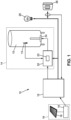
Un dispositif de stockage d'énergie utilisant un chauffe-eau 12 alimentant un local, par exemple une habitation, en eau chaude sanitaire est référencé 10 sur la
L'installation 10 de stockage d'énergie inclut un dispositif de chauffage d'eau 14 destiné à alimenter l'habitation en eau chaude, un gestionnaire d'énergie 15 en communication avec le dispositif de chauffage d'eau 14 pour moduler le chauffage de l'eau, et un système photovoltaïque 16 approvisionnant le dispositif de chauffage d'eau 14 en énergie pour le chauffage de l'eau. Le dispositif de chauffage d'eau 14 est aussi alimenté en énergie par le réseau électrique.The
Le système photovoltaïque 16 comprend un ou plusieurs panneaux photovoltaïques 18 qui convertissent une lumière reçue en courant continu, et un convertisseur 19 qui convertit le courant continu produit par les panneaux photovoltaïques 18 en courant alternatif. Il est entendu que le convertisseur 19 pourrait être optionnel.The
Le dispositif de chauffage d'eau 14 comprend un chauffe-eau 12 piloté par une carte de régulation 22.The
Le chauffe-eau 12 peut être un chauffe-eau électrique ou thermodynamique. Le chauffe-eau 12 pourrait aussi avoir des éléments de chauffage thermodynamique et électrique combinés.The
Le chauffe-eau 12 inclut un thermomètre 13 permettant de connaître une température de l'eau contenue dans le chauffe-eau 12, et un organe de chauffe 24 pour chauffer de l'eau contenue dans le chauffe-eau 12 en fonction notamment de commandes émises par la carte de régulation 22. Dans le cas d'un chauffe-eau thermodynamique, l'organe de chauffe 24 serait par exemple une pompe à chaleur avec vitesse de compresseur variable. Dans le cas d'un chauffe-eau électrique, l'organe de chauffe 24 inclurait par exemple une ou plusieurs résistances (fixes ou variables) connectées à une ou plusieurs épingles. Un exemple d'organe de chauffe 24 pour un chauffe-eau électrique sera décrit ci-dessous en conjonction avec la
La carte de régulation 22 est une carte électronique qui comporte plusieurs entrées logiques afin de moduler la puissance de chauffe de l'organe de chauffe 24 en fonction du surplus d'énergie photovoltaïque produit. La carte de régulation 22 inclut un module de calcul 23, qui est en communication avec le gestionnaire d'énergie 15 et le thermomètre 13. Le module de calcul 23 permet de déterminer à quel moment chauffer l'eau du chauffe-eau 12 (notamment par les données du thermomètre 13), mais aussi de réguler les apports en énergie entre l'énergie électrique du réseau et celle produite par le système photovoltaïque 16, afin d'optimiser l'apport en énergie photovoltaïque.The
Par exemple, le module de calcul 23 détermine une puissance de chauffe en fonction au moins du surplus éventuel d'énergie photovoltaïque, de la température de l'eau dans le chauffe-eau 12 et d'une consigne de température. La consigne de température est une température de référence à laquelle l'eau dans le chauffe-eau 12 doit se trouver (i.e. température maximale de chauffe). La consigne de température a plusieurs valeurs selon qu'un surplus d'énergie photovoltaïque est présent.For example, the
Une valeur de base de la consigne de température est une température maximum admissible par l'utilisateur pour l'eau qui lui est délivrée. Par exemple, si l'utilisateur désire une température maximale de 55 degrés Celsius, la valeur de base de la consigne de température sera 55 degrés. La valeur de base de la consigne de température pourrait être transmise à la carte de régulation 22 par l'utilisateur par l'intermédiaire d'une interface (par exemple un clavier).A base value of the temperature set point is a maximum temperature acceptable by the user for the water delivered to him. For example, if the user wants a maximum temperature of 55 degrees Celsius, the base value of the temperature set point will be 55 degrees. The base value of the temperature setpoint could be transmitted to the
La consigne de température a aussi une valeur haute, valeur de surplus Tsur, qui est supérieure à la valeur de base et qui est la température maximum atteignable lorsqu'un surplus d'énergie photovoltaïque est disponible. Ainsi, lorsqu'un surplus d'énergie photovoltaïque est disponible, la carte de régulation 22 chauffe l'eau afin de convertir le surplus d'énergie photovoltaïque en énergie thermique, utilisable par l'utilisateur instantanément ou dans un futur proche.The temperature setpoint also has a high value, surplus value Tsur, which is greater than the base value and which is the maximum temperature that can be reached when a surplus of photovoltaic energy is available. Thus, when a surplus of photovoltaic energy is available, the
Cette température peut être transmise à la carte de régulation 22 par l'utilisateur par l'intermédiaire de l'interface, ou bien être calculée par la carte de régulation en fonction de la valeur de base de la consigne de température. La valeur de surplus de la consigne de température Tsur est par exemple 70 degrés Celsius.This temperature can be transmitted to the
L'installation 10 peut inclure un mitigeur thermostatique connecté au chauffe-eau 12. Le mitigeur pourrait, par exemple, se trouver en sortie du chauffe-eau 12. Le mitigeur thermostatique est adapté à délivrer l'eau du chauffe-eau 12 sur une échelle de température basée sur la valeur de base de la consigne de température Tbas. Le mitigeur thermostatique peut délivrer l'eau du chauffe-eau 12 à une température maximale égale à la valeur de base de la consigne de température même si la température de l'eau du chauffe-eau 12 est à température au-dessus de la valeur de base, par exemple lorsqu'il est à la valeur de surplus.The
Une fois la puissance de chauffe déterminée par le module de calcul 22 selon un procédé détaillé ci-dessous, celui-ci transmet la transmet à l'organe de chauffe 24 pour chauffer l'eau de façon correspondante.Once the heating power has been determined by the
Le thermomètre 13 permet de vérifier si l'eau atteint la consigne de température et de stopper le chauffage à ce moment-là, via la carte de régulation 22.The
Dans un mode de réalisation, le gestionnaire d'énergie 15 en coopération avec la carte de régulation 22 permet de stocker un surplus d'énergie produite par les panneaux photovoltaïques 18 en énergie thermique. En effet, dans certains cas, il se peut que le système photovoltaïque 16 produise plus d'énergie que ce que le dispositif de chauffage d'eau 14 (et possiblement aussi les appareils électriques 20) ne requièrent. Grâce à l'installation et procédé décrits ci-dessous, au moins une partie de ce surplus d'énergie photovoltaïque produit peut être réinjectée dans le dispositif de chauffage d'eau 14 au lieu d'être injectée à perte au réseau d'alimentation. Ainsi, l'énergie qui aurait dû être retournée au réseau (donc à perte) est transformée en énergie thermique en chauffant l'eau du chauffe-eau de façon additionnelle à son fonctionnement habituel. Le dispositif de chauffage d'eau 14 fonctionne alors comme un stockage d'énergie, en convertissant de l'énergie électrique produite en surplus par le système photovoltaïque 16 en énergie thermique (eau chauffée). Si le surplus est plus important que la puissance de chauffe possible par le chauffe-eau, la différence pourrait être réinjectée dans le réseau.In one embodiment, the
Afin de déterminer ce surplus, le gestionnaire d'énergie 15 compare l'énergie produite par les panneaux photovoltaïques 18 avec l'énergie consommée par l'habitation. Le gestionnaire d'énergie 15 peut, par exemple, recevoir différents signaux de micro-onduleurs des panneaux photovoltaïques 18. Dans un autre mode de réalisation, un tore sur une ligne de réseau connectée à un compteur 26 du local détermine une énergie produite par le système photovoltaïque 16 et non consommée. Dans un autre mode de réalisation, les compteurs Linky ou un autre pourraient être utilisés. Le gestionnaire d'énergie 15 pourrait être intégré au système photovoltaïque 16.In order to determine this surplus, the
Dans un mode de réalisation, afin de communiquer avec la carte de régulation 22, le gestionnaire d'énergie 15 émet à destination de la carte de régulation 22 un signal. Le signal pourrait être un signal de tension ou d'intensité selon le destinataire de ce signal. Ce signal est par exemple un signal 0/230V. Le gestionnaire d'énergie 15 pourrait ne pas communiquer par voie filaire. Par exemple, une liaison radio pourrait être utilisée entre le gestionnaire d'énergie 15 et la carte de régulation 22.In one embodiment, in order to communicate with the
Le gestionnaire d'énergie 15 pourrait aussi réguler, en coopération avec la carte de régulation 22, la fonction du chauffe-eau 12 en fonction d'autres facteurs que le surplus d'énergie photovoltaïque immédiatement disponible.The
Par exemple, le chauffe-eau 12 pourrait chauffer l'eau exclusivement avec le surplus de production des panneaux pendant les périodes diurnes. Ainsi le stockage d'énergie serait favorisé. Si la chauffe du ballon est réalisée en période diurne par le recours à l'énergie photovoltaïque, l'énergie du réseau pourrait n'être utilisée que pour gérer les manques en chaude. Hors période diurne (i.e. période nocturne), le chauffe-eau 12 pourrait être autorisé à utiliser l'énergie du réseau électrique.For example, the
Selon un autre méthode de fonctionnement, le chauffe-eau 12 est autorisé à utiliser l'énergie du réseau même pendant les périodes de production des panneaux photovoltaïques 18, c'est-à-dire, même pendant les périodes diurnes.According to another method of operation, the
Selon un mode de fonctionnement, le mode de fonctionnement nocturne peut être anticipé en fin de phase diurne (c'est-à-dire, le mode de fonctionnement nocturne est activé en période diurne avant le coucher de soleil) si la production d'énergie photovoltaïque a été faible dans la journée. Ce mode de fonctionnement pourrait éviter aux usagers d'avoir de l'eau froide en fin de journée si l'ensoleillement est insuffisant, et ainsi améliorer le confort des usagers. Le système pourrait alors utiliser l'énergie du réseau pour pallier aux manques photovoltaïques afin que l'usager ait de l'eau chaude en fin de journée.According to an operating mode, the nighttime operating mode can be anticipated at the end of the daytime phase (that is to say, the nighttime operating mode is activated during the daytime period before sunset) if the energy production photovoltaic was weak during the day. This mode of operation could prevent users from having cold water at the end of the day if the sunshine is insufficient, and thus improve user comfort. The system could then use the network's energy to compensate for photovoltaic shortages so that the user has hot water at the end of the day.
Le gestionnaire d'énergie 15 et/ou la carte de régulation 22 pourrait être connecté à un serveur ou un cloud pour recevoir par exemple des données météorologiques en particulier pour intégrer les prévisions journalières d'ensoleillement pour n'utiliser la ou les résistances complémentaires que si le potentiel de production des panneaux photovoltaïques 18 est insuffisant au cours de la journée.The
Le gestionnaire d'énergie 15 pourrait aussi prendre en compte les habitudes de consommation de l'habitation pour réguler l'utilisation du surplus d'énergie photovoltaïque. Par exemple, le gestionnaire d'énergie 15 et/ou la carte de régulation 22 pourrait enregistrer la consommation sur les dernières 24 heures et en déduire un profil utilisateur afin de déterminer des besoins en eau chaude à assurer à certaines plages horaires. La valeur de base de la consigne de température pourrait alors varier dans le temps pour permettre un stockage d'eau chaude avant les périodes usuelles de consommation suivant le profil utilisateur.The
En se référant maintenant à la
Par exemple, si la résistance R1 peut produire une puissance de 1600W, la résistance R2 de 800W, et la résistance R3 de 400W, alors l'utilisation (1 - dans le tableau ci-dessous) ou la non utilisation (0 - dans le tableau ci-dessous) de cette résistance en fonction des autres donne les sept valeurs de puissance totale Ptotal :
Si le gestionnaire d'énergie 15 détermine qu'une puissance de 2400W est en surplus (après avoir alimenté les appareils 20 et le chauffe-eau 12 en usage normal), et que cette puissance peut être stockée en chauffant l'eau du chauffe-eau 12 au-delà de sa température d'usage normal, le gestionnaire d'énergie 15 envoie, via le module de calcul 31, une commande à la carte de régulation 30 de fermer les relais I1 et I2 correspondants aux résistances R1 et R3, et d'ouvrir le relai I3 correspondant à la résistance I3. Ainsi, seules les résistances R1 et R2 sont actives et leur puissance associée est 1600+800=2400W.If the
Bien entendu, l'organe de chauffe 32 pourrait avoir seulement une, ou deux ou plus de trois résistances 36, et ainsi seulement un, deux ou plus de trois relais 34 associés. Dans le cas où l'organe de chauffe 32 aurait deux résistances 36, il y aurait potentiellement quatre puissances associées. On note également que certaines ou toutes les résistances 36 pourraient avoir une même valeur, ou des valeurs différentes. Par ailleurs, au moins une des résistances 36 pourrait être une résistance variable. L'organe de chauffe 32 pourrait avoir une seule résistance variable ou bien une combinaison de résistances variables et fixes.Of course, the
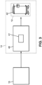
En se référant maintenant à la
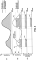
La
Le graphe G1 montre que l'énergie produite par le système photovoltaïque 16 (ligne continue) et l'énergie consommée par l'habitation (ligne pointillée) varient l'une par rapport à l'autre. Ainsi il existe des périodes où il y a plus d'énergie produite par le système photovoltaïque 16 que d'énergie consommée (i.e. surplus, zone en grisée). Ce surplus est aussi illustré dans le graphe G2 par une ligne de pointillés mixtes.Graph G1 shows that the energy produced by the photovoltaic system 16 (solid line) and the energy consumed by the dwelling (dotted line) vary relative to each other. Thus there are periods when there is more energy produced by the
En référant au graphe G2, lorsqu'un premier seuil S1 de surplus est atteint et tant que le surplus est au-dessus de ce seuil S1, le gestionnaire d'énergie 15 commande la carte de régulation 30 (ou 40) de façon à chauffer à cette puissance. La puissance disponible est le surplus disponible au seuil S1 pour toute la durée de temps pour lequel le seuil S1 est atteint (parties hachurée P1).Referring to graph G2, when a first surplus threshold S1 is reached and as long as the surplus is above this threshold S1, the
Dans le mode de réalisation de la
Si un deuxième seuil S2 de surplus est atteint (S2 étant supérieur à S1), et tant que le surplus est au-dessus de ce seuil S2, la carte de régulation 30 commande une puissance de chauffe P2 supérieure à P1.If a second surplus threshold S2 is reached (S2 being greater than S1), and as long as the surplus is above this threshold S2, the
Dans le mode de réalisation de la
Dans le mode de réalisation de la
Un seuil maximal atteignable (par exemple le seuil S2) est fonction des caractéristiques mécaniques de l'organe de chauffe 24.A maximum attainable threshold (for example the threshold S2) depends on the mechanical characteristics of the
Il se pourrait aussi que le système fonctionne sans paliers tels que les seuils S1 et S2. Ceci pourrait être par exemple réalisable avec le compresseur dans le cas d'un chauffe-eau thermodynamique ou avec une résistance variable de sorte qu'ils aient leur puissance modulable en temps réel en fonction de la fluctuation du surplus. Il se pourrait aussi que le système fonctionne de façon discrète (i.e. avec des paliers) seulement pour certaines puissances ou à certaines heures de la journée, et de façon continue pour le reste.It could also be that the system operates without stages such as thresholds S1 and S2. This could for example be achieved with the compressor in the case of a thermodynamic water heater or with a variable resistor so that their power can be modulated in real time according to the fluctuation of the surplus. It could also be that the system operates discreetly (i.e. with levels) only for certain powers or at certain times of the day, and continuously for the rest.
Un procédé de stockage d'énergie utilisant n'importe quelle installation décrite ci-dessus va maintenant être décrit.An energy storage method using any of the facilities described above will now be described.
Le procédé de stockage d'énergie commence par une surveillance de la température de l'eau Teau contenue dans le chauffe-eau 12 par le thermomètre 13. Si le thermomètre 13 mesure une température Teau de l'eau égale ou supérieure à une valeur de base de la consigne de température Tbas, la carte de régulation 22 ne commande pas l'organe de chauffe 24 tant qu'aucun surplus d'énergie est produit par le système photovoltaïque 16. C'est-à-dire que si l'eau du chauffe-eau 12 est déjà assez chaude et qu'il n'y a pas de surplus photovoltaïque (ou que le surplus photovoltaïque est si faible qu'il ne permet pas un stockage d'énergie sous forme thermique), il n'y a pas de besoin pour chauffer l'eau de façon supplémentaire.The energy storage method begins with monitoring the temperature of the water Teau contained in the
Par contre, si le gestionnaire d'énergie 15 communique à la carte de régulation 22 qu'un surplus d'énergie est produit par le système photovoltaïque 16, la carte de régulation 22 commande l'organe de chauffe 24 de chauffer l'eau même si l'eau est déjà à une température au-dessus de la consigne de base. Il se pourrait que le surplus d'énergie disponible soit plus faible que la valeur minimum de puissance de l'organe de chauffe 24, dans quel cas, la carte de régulation 22 ne commanderait pas l'organe de chauffe 24 de chauffer l'eau.On the other hand, if the
Lorsqu'un surplus d'énergie est disponible, la carte de régulation 22 commande l'organe de chauffe 24 afin de chauffer l'eau en utilisant le surplus, et ceci autant que le surplus est disponible, tout en étant en dessous de la valeur de surplus de la consigne de température Tsur. Le chauffage de l'eau se fait donc par l'énergie photovoltaïque en surplus (et non pas par l'énergie électrique du réseau) qui serait sinon réinjectée dans le réseau (et donc perdue). Selon le surplus disponible, le surplus peut permettre de chauffer l'eau à la valeur de base de la consigne de température ou à une valeur plus haute (tout en étant égale ou inférieure à la valeur de surplus de la consigne de température). En chauffant le chauffe-eau 12 au-delà de la température maximum désirée par l'utilisateur, le chauffe-eau 12 est utilisé comme moyen de stockage d'énergie en stockant l'énergie voltaïque en eau chaude en prévision de consommations futures.When a surplus of energy is available, the
L'information de surplus d'énergie photovoltaïque est communiquée à la carte de régulation 22 par le gestionnaire d'énergie 15. Le gestionnaire d'énergie 15 détermine une puissance de chauffe correspondant au moins à une partie du surplus d'énergie produit et non consommé par le système photovoltaïque 16. Le gestionnaire d'énergie 15 prend en compte l'information d'énergie non consommée, mais pourrait aussi prendre en compte d'autres informations, telles que des données sur des profils antérieurs de consommation du chauffe-eau 12 (pour par exemple s'assurer qu'ils sont en adéquation avec les perspectives de disponibilité énergétique des panneaux photovoltaïques 18 et éviter tout recours au réseau, ceci afin de s'approcher ou de réaliser un chauffe-eau 12 autonome).The photovoltaic energy surplus information is communicated to the
La carte de régulation 22 envoie à l'organe de chauffe 24 une commande d'activation l'organe de chauffe 24 à la puissance de chauffe pour chauffer l'eau contenue dans le chauffe-eau 12. Dans le cas où la carte de régulation 22 a plusieurs entrées logiques, les entrées logiques qui permettent de combiner les résistances R1, R2, R3 (via les relais I1, I2, I3) de façon à atteindre la puissance de chauffe disponible, sont activées. Dans le cas de la carte de régulation 40 et de la pompe à chaleur, la carte de régulation 40 commande le compresseur à une vitesse correspondant à la puissance de chauffe déterminée.The
Dans un mode de réalisation, la puissance de chauffe serait ajustable en temps réel en fonction du surplus d'énergie. Dans un autre mode de réalisation, la puissance de chauffe serait ajustable par incrément de temps prédéterminés (par exemple toutes les cinq minutes).In one embodiment, the heating power would be adjustable in real time depending on the energy surplus. In another embodiment, the heating power would be adjustable by predetermined time increments (for example every five minutes).
Si le thermomètre 13 mesure une température Teau de l'eau contenue dans le chauffe-eau 12 inférieure à la valeur de base de la consigne de température Tbas, et si le gestionnaire d'énergie 15 communique à la carte de régulation 22 qu'aucun surplus d'énergie est produit par le système photovoltaïque 16, alors la carte de régulation 22 commande l'organe de chauffe 24 de chauffer l'eau jusqu'à la valeur de base de la consigne de température Tbas en utilisant de l'énergie autre que celle produite par le système photovoltaïque 16, c'est-à-dire, l'énergie du réseau.If the
Si le thermomètre 13 mesure une température Teau de l'eau contenue dans le chauffe-eau 12 inférieure à la valeur de base de la consigne de température Tbas, et si le gestionnaire d'énergie 15 communique à la carte de régulation 22 qu'un surplus d'énergie est produit par le système photovoltaïque 16, la carte de régulation 22 commande l'organe de chauffe 24 de chauffer l'eau en utilisant l'énergie produite par le système photovoltaïque 16 en fonction du surplus jusqu'à une valeur de surplus de la consigne de température Tsur, la valeur de surplus de la consigne de température Tsur étant supérieure à la valeur de base de la consigne de température Tbas.If the
Selon un mode de fonctionnement, lorsque la puissance de chauffe provenant du surplus photovoltaïque est inférieure à la valeur de surplus de la consigne de température Tsur, la carte de régulation 22 pourrait commander l'organe de chauffe 24 de façon à chauffer l'eau jusqu'à la valeur de base de la consigne de température Tbas en utilisant, de façon complémentaire à l'énergie provenant du surplus photovoltaïque, de l'énergie autre que celle produite par le système photovoltaïque 16, c'est à dire de l'énergie du réseau électrique. Ceci pourrait plus particulièrement être implémenté pendant les phases nocturnes où l'énergie photovoltaïque diminue.According to one mode of operation, when the heating power coming from the photovoltaic surplus is lower than the surplus value of the temperature set point Tsur, the
L'installation 10 et procédé de stockage d'énergie décrits ci-dessous permettent de stocker un surplus d'énergie produite par les panneaux photovoltaïques 18, qui serait sinon injecté au réseau d'alimentation, en énergie thermique, sous forme d'eau chauffée disponible dans le chauffe-eau 12.The
Le procédé est applicable aux systèmes utilisant des chauffe-eau électriques et/ou thermodynamiques. L'installation 10 peut utiliser des composants simples tels que les relais I1, I2, I3 pour effectuer la modulation de puissance électrique. De plus, l'intégration des composants servant à l'application du procédé est minimale, et l'installation 10 est adaptable à divers environnements, notamment implantable sur des chauffe-eau existants.The method is applicable to systems using electric and/or thermodynamic water heaters. The
Claims (12)
- Energy storage facility (10) comprising:a photovoltaic system,energy production means other than the photovoltaic system, anda water heating device (14) intended for supplying a room with hot water, the water heating device comprising:a water heater (12) including:- a heating member (24) for heating water contained in the water heater (12),- a thermometer (13) for measuring a temperature of the water Teau contained in the water heater (12); anda regulating board (22) connected to the heating member (24) and to the thermometer (13), the regulating board (22) being suitable for regulating the heating member (24) according to energy received by the photovoltaic system (16) and energy received by the means other than the photovoltaic system (16),the regulating board (22) being suitable for determining a heating power to be controlled from the heating member (24) according to a temperature setpoint, the temperature setpoint having a base value Tbas, and a surplus value Tsur greater than the base value Tbas;the facility being characterizedin that it comprises an energy manager (15) connected to the regulating board (22) and to the photovoltaic system (16), the energy manager (15) being suitable for communicating to the regulating board (22) that a surplus of energy produced by the photovoltaic system (16) is available, and in addition when the temperature of the water contained in the water heater (12) is lower than the surplus value Tsur of the temperature setpoint, the regulating board (22) being suitable for determining from the available surplus a heating power to be controlled from the heating member (24) in order to store at least a portion of the surplus in the form of hot water available in the water heater (12), and the regulating board controlling the heating member to heat the water of the water heater using the surplus photovoltaic energy as long as the water temperature is lower than the surplus value Tsur.
- Facility according to claim 1, wherein the base value of the temperature setpoint is a function of previous hot water consumption from the water heater (12), characteristics of the water heater (12), and/or consumption projections.
- Facility according to one of claims 1 or 2, wherein the heating member (24) of the water heater (12) is electric and/or thermodynamic.
- Facility according to claim 3, wherein the heating member (24) of the water heater (12) includes an electrical element, the electrical element including a plurality of resistors, the resistors being each coupled to a relay, the relays being connected to the regulating board, the regulating board being suitable for determining the relays to be actuated according to the surplus value of the temperature setpoint.
- Facility according to claim 3, wherein the heating member of the water heater includes a heat pump (42) with variable compressor speed, the regulating board being suitable for controlling a speed of the compressor.
- Facility according to one of claims 1 to 5, further including a thermostatic mixing valve, the thermostatic mixing valve being suitable for delivering water from the water heater (12) at a maximum temperature equal to the base value of the temperature setpoint when the temperature of the water of the water heater (12) is at or above the base value of the temperature set point.
- Method for regulating a facility according to any one of claims 1 to 6, wherein, if the energy manager (15) communicates to the regulating board (22) that a surplus of energy is being produced by the photovoltaic system (16), the regulating board (22) controls the heating member (24) to heat the water using the surplus energy produced by the photovoltaic system (16), the heating power heating the water to a temperature less than or equal to a surplus value of the temperature setpoint Tsur, the surplus value of the temperature setpoint Tsur being greater than the base value of the temperature setpoint Tbas.
- Method according to claim 7, wherein if the thermometer (13) measures a temperature Teau of the water contained in the water heater (12) that is greater than or equal to the base value of the temperature setpoint Tbas, the regulating board (22) does not control the heating member (24) as long as no surplus energy produced by the photovoltaic system (16) is available.
- Method according to claim 7 or 8, wherein if the thermometer (13) measures a temperature Teau of the water contained in the water heater (12) that is less than the base value of the temperature setpoint Tbas and if the energy manager (15) communicates to the regulating board (22) that no surplus energy is being produced by the photovoltaic system (16), the regulating board (22) controls the heating member (24) to heat the water up to the base value of the temperature setpoint Tbas using energy other than that produced by the photovoltaic system (16).
- Method according to claim 7, wherein according to one mode of operation, when the heating power from the photovoltaic surplus is less than the surplus value of the temperature set Tsur, the regulating board (22) controls the heating member (24) to heat the water up to the base value of the temperature setpoint Tbas using, in addition to the energy from the photovoltaic surplus, energy other than that produced by the photovoltaic system (16).
- Method according to claim 10, wherein the mode of operation is a nighttime mode of operation.
- Method according to claim 11, wherein the nighttime mode of operation is activated during the daytime period before sunset.
Applications Claiming Priority (1)
| Application Number | Priority Date | Filing Date | Title |
|---|---|---|---|
| FR1754477A FR3066582B1 (en) | 2017-05-19 | 2017-05-19 | ENERGY STORAGE PROCESS AND INSTALLATION USING A WATER HEATER |
Publications (3)
| Publication Number | Publication Date |
|---|---|
| EP3404334A1 EP3404334A1 (en) | 2018-11-21 |
| EP3404334B1 EP3404334B1 (en) | 2020-08-19 |
| EP3404334B2 true EP3404334B2 (en) | 2023-08-09 |
Family
ID=59699824
Family Applications (1)
| Application Number | Title | Priority Date | Filing Date |
|---|---|---|---|
| EP18173151.4A Active EP3404334B2 (en) | 2017-05-19 | 2018-05-18 | Method and facility for energy storage using a water heater |
Country Status (5)
| Country | Link |
|---|---|
| EP (1) | EP3404334B2 (en) |
| ES (1) | ES2829569T5 (en) |
| FR (1) | FR3066582B1 (en) |
| PL (1) | PL3404334T5 (en) |
| PT (1) | PT3404334T (en) |
Families Citing this family (5)
| Publication number | Priority date | Publication date | Assignee | Title |
|---|---|---|---|---|
| FR3102835B1 (en) * | 2019-10-30 | 2022-06-24 | Atlantic Industrie Sas | WATER HEATER DEVICE |
| EP4267888A1 (en) * | 2020-12-22 | 2023-11-01 | Premier Energy Holdings, Inc. | Converting solar pv energy into thermal energy storage using heat-pump and resistive heating elements in water heater |
| WO2022195007A1 (en) | 2021-03-19 | 2022-09-22 | Wanit S.A. | System for managing a variable-power dc current source |
| FR3136539A1 (en) * | 2022-06-13 | 2023-12-15 | Solarindep | Heating and/or air conditioning system |
| EP4355025A1 (en) * | 2022-10-11 | 2024-04-17 | BDR Thermea Group B.V. | Heat pump system with supplemental heating system and method for controlling thereof |
Citations (2)
| Publication number | Priority date | Publication date | Assignee | Title |
|---|---|---|---|---|
| DE102011090141A1 (en) † | 2011-12-29 | 2013-07-04 | Werner Schmid | Method and device for using electrical energy of a device connected to a household power network for generating renewable electrical energy |
| DE102014011331A1 (en) † | 2013-09-11 | 2015-04-02 | Klaus Rauch | Apparatus and method for regulating the storage of electrical energy in the form of heat |
Family Cites Families (3)
| Publication number | Priority date | Publication date | Assignee | Title |
|---|---|---|---|---|
| US10571135B2 (en) * | 2012-04-09 | 2020-02-25 | David Kreutzman | Renewable energy hot water heater with heat pump |
| US20140153913A1 (en) * | 2012-12-05 | 2014-06-05 | Energy Laboratories, Inc. | Solar Photovoltaic Water Heating System |
| FR3033391A1 (en) * | 2015-03-02 | 2016-09-09 | Electricite De France | WATER HEATER SYSTEM WITH DEDICATED PHOTOVOLTAIC INSTALLATION |
-
2017
- 2017-05-19 FR FR1754477A patent/FR3066582B1/en active Active
-
2018
- 2018-05-18 PL PL18173151.4T patent/PL3404334T5/en unknown
- 2018-05-18 ES ES18173151T patent/ES2829569T5/en active Active
- 2018-05-18 EP EP18173151.4A patent/EP3404334B2/en active Active
- 2018-05-18 PT PT181731514T patent/PT3404334T/en unknown
Patent Citations (2)
| Publication number | Priority date | Publication date | Assignee | Title |
|---|---|---|---|---|
| DE102011090141A1 (en) † | 2011-12-29 | 2013-07-04 | Werner Schmid | Method and device for using electrical energy of a device connected to a household power network for generating renewable electrical energy |
| DE102014011331A1 (en) † | 2013-09-11 | 2015-04-02 | Klaus Rauch | Apparatus and method for regulating the storage of electrical energy in the form of heat |
Also Published As
| Publication number | Publication date |
|---|---|
| ES2829569T3 (en) | 2021-06-01 |
| PL3404334T5 (en) | 2023-12-04 |
| EP3404334A1 (en) | 2018-11-21 |
| PL3404334T3 (en) | 2021-03-22 |
| FR3066582B1 (en) | 2021-02-12 |
| PT3404334T (en) | 2020-11-09 |
| EP3404334B1 (en) | 2020-08-19 |
| ES2829569T5 (en) | 2024-03-26 |
| FR3066582A1 (en) | 2018-11-23 |
Similar Documents
| Publication | Publication Date | Title |
|---|---|---|
| EP3404334B2 (en) | Method and facility for energy storage using a water heater | |
| EP3676541B1 (en) | Heating apparatus comprising a battery and a power inverter for introducing energy from the battery to the electrical supply source | |
| EP3117158B1 (en) | Electric water heater with adjustable power | |
| WO2012034965A1 (en) | Low-power residential heating system | |
| EP0148700B1 (en) | Method and device to control a space heating installation, comprising a plurality of heat generators | |
| FR3033391A1 (en) | WATER HEATER SYSTEM WITH DEDICATED PHOTOVOLTAIC INSTALLATION | |
| WO2015197622A1 (en) | Power management method in an electrical installation and an electrical installation | |
| FR3074264A1 (en) | HEATING SYSTEM FOR SANITARY WATER | |
| CA3044348C (en) | Electric radiator type heating apparatus including a voltage converter | |
| WO2021140251A1 (en) | Heating system and method | |
| EP3340004B1 (en) | Method for determining the load-shedding capability of a building using thermal inertia, associated load-shedding method and system using said methods | |
| EP3816524B1 (en) | Device for heating water | |
| EP1008922B1 (en) | Method of controlling the load of at least one heating device and in particular of an electrical one with heat accumulator and/or the thermal capacity of construction elements and equipment; device for implementing the method | |
| EP3650762A1 (en) | Method for controlling a thermal power to be injected in a heating system and heating system implementing said method | |
| EP3816760A2 (en) | Method for managing, in a tank, a volume of water in which the temperature is higher than a predetermined temperature | |
| EP3258187B1 (en) | Method for modifying the power consumption of a device | |
| FR3008484A1 (en) | ENERGY PRODUCTION PLANT COMPRISING A WEATHER PREDICTION DEVICE, IN PARTICULAR A SOLAR WATER HEATER INSTALLATION COMPRISING SUCH A DEVICE | |
| EP2784896A1 (en) | System for managing electricity production and consumption | |
| EP3671399B1 (en) | Method for determining a preferential minimum power setting, method for controlling a plurality of water heaters and associated device | |
| EP0542653A1 (en) | Process and installation for heating a room or the like, using at least one storage heater | |
| FR3104843A1 (en) | Micro-grid with a sophisticated balance between consumption and production | |
| WO2022195007A1 (en) | System for managing a variable-power dc current source | |
| EP2886701A1 (en) | System of boiler and equipment consuming hot water | |
| FR2793643A1 (en) | Electric heating control system for underfloor heaters controls activation of electric heaters in response of comfort level signal delivered by programmer for each tariff interval | |
| FR3102836A1 (en) | WATER HEATING DEVICE |
Legal Events
| Date | Code | Title | Description |
|---|---|---|---|
| PUAI | Public reference made under article 153(3) epc to a published international application that has entered the european phase |
Free format text: ORIGINAL CODE: 0009012 |
|
| STAA | Information on the status of an ep patent application or granted ep patent |
Free format text: STATUS: THE APPLICATION HAS BEEN PUBLISHED |
|
| AK | Designated contracting states |
Kind code of ref document: A1 Designated state(s): AL AT BE BG CH CY CZ DE DK EE ES FI FR GB GR HR HU IE IS IT LI LT LU LV MC MK MT NL NO PL PT RO RS SE SI SK SM TR |
|
| AX | Request for extension of the european patent |
Extension state: BA ME |
|
| STAA | Information on the status of an ep patent application or granted ep patent |
Free format text: STATUS: REQUEST FOR EXAMINATION WAS MADE |
|
| 17P | Request for examination filed |
Effective date: 20190520 |
|
| RBV | Designated contracting states (corrected) |
Designated state(s): AL AT BE BG CH CY CZ DE DK EE ES FI FR GB GR HR HU IE IS IT LI LT LU LV MC MK MT NL NO PL PT RO RS SE SI SK SM TR |
|
| RAP1 | Party data changed (applicant data changed or rights of an application transferred) |
Owner name: ATLANTIC INDUSTRIE |
|
| GRAP | Despatch of communication of intention to grant a patent |
Free format text: ORIGINAL CODE: EPIDOSNIGR1 |
|
| STAA | Information on the status of an ep patent application or granted ep patent |
Free format text: STATUS: GRANT OF PATENT IS INTENDED |
|
| INTG | Intention to grant announced |
Effective date: 20200313 |
|
| GRAS | Grant fee paid |
Free format text: ORIGINAL CODE: EPIDOSNIGR3 |
|
| GRAA | (expected) grant |
Free format text: ORIGINAL CODE: 0009210 |
|
| STAA | Information on the status of an ep patent application or granted ep patent |
Free format text: STATUS: THE PATENT HAS BEEN GRANTED |
|
| AK | Designated contracting states |
Kind code of ref document: B1 Designated state(s): AL AT BE BG CH CY CZ DE DK EE ES FI FR GB GR HR HU IE IS IT LI LT LU LV MC MK MT NL NO PL PT RO RS SE SI SK SM TR |
|
| REG | Reference to a national code |
Ref country code: CH Ref legal event code: EP |
|
| REG | Reference to a national code |
Ref country code: DE Ref legal event code: R096 Ref document number: 602018006989 Country of ref document: DE |
|
| REG | Reference to a national code |
Ref country code: AT Ref legal event code: REF Ref document number: 1304362 Country of ref document: AT Kind code of ref document: T Effective date: 20200915 |
|
| REG | Reference to a national code |
Ref country code: IE Ref legal event code: FG4D Free format text: LANGUAGE OF EP DOCUMENT: FRENCH |
|
| REG | Reference to a national code |
Ref country code: PT Ref legal event code: SC4A Ref document number: 3404334 Country of ref document: PT Date of ref document: 20201109 Kind code of ref document: T Free format text: AVAILABILITY OF NATIONAL TRANSLATION Effective date: 20201030 |
|
| REG | Reference to a national code |
Ref country code: CH Ref legal event code: NV Representative=s name: VALIPAT S.A. C/O BOVARD SA NEUCHATEL, CH |
|
| REG | Reference to a national code |
Ref country code: LT Ref legal event code: MG4D |
|
| REG | Reference to a national code |
Ref country code: NL Ref legal event code: MP Effective date: 20200819 |
|
| PG25 | Lapsed in a contracting state [announced via postgrant information from national office to epo] |
Ref country code: GR Free format text: LAPSE BECAUSE OF FAILURE TO SUBMIT A TRANSLATION OF THE DESCRIPTION OR TO PAY THE FEE WITHIN THE PRESCRIBED TIME-LIMIT Effective date: 20201120 Ref country code: LT Free format text: LAPSE BECAUSE OF FAILURE TO SUBMIT A TRANSLATION OF THE DESCRIPTION OR TO PAY THE FEE WITHIN THE PRESCRIBED TIME-LIMIT Effective date: 20200819 Ref country code: HR Free format text: LAPSE BECAUSE OF FAILURE TO SUBMIT A TRANSLATION OF THE DESCRIPTION OR TO PAY THE FEE WITHIN THE PRESCRIBED TIME-LIMIT Effective date: 20200819 Ref country code: BG Free format text: LAPSE BECAUSE OF FAILURE TO SUBMIT A TRANSLATION OF THE DESCRIPTION OR TO PAY THE FEE WITHIN THE PRESCRIBED TIME-LIMIT Effective date: 20201119 Ref country code: SE Free format text: LAPSE BECAUSE OF FAILURE TO SUBMIT A TRANSLATION OF THE DESCRIPTION OR TO PAY THE FEE WITHIN THE PRESCRIBED TIME-LIMIT Effective date: 20200819 Ref country code: FI Free format text: LAPSE BECAUSE OF FAILURE TO SUBMIT A TRANSLATION OF THE DESCRIPTION OR TO PAY THE FEE WITHIN THE PRESCRIBED TIME-LIMIT Effective date: 20200819 Ref country code: NO Free format text: LAPSE BECAUSE OF FAILURE TO SUBMIT A TRANSLATION OF THE DESCRIPTION OR TO PAY THE FEE WITHIN THE PRESCRIBED TIME-LIMIT Effective date: 20201119 |
|
| PG25 | Lapsed in a contracting state [announced via postgrant information from national office to epo] |
Ref country code: RS Free format text: LAPSE BECAUSE OF FAILURE TO SUBMIT A TRANSLATION OF THE DESCRIPTION OR TO PAY THE FEE WITHIN THE PRESCRIBED TIME-LIMIT Effective date: 20200819 Ref country code: LV Free format text: LAPSE BECAUSE OF FAILURE TO SUBMIT A TRANSLATION OF THE DESCRIPTION OR TO PAY THE FEE WITHIN THE PRESCRIBED TIME-LIMIT Effective date: 20200819 Ref country code: NL Free format text: LAPSE BECAUSE OF FAILURE TO SUBMIT A TRANSLATION OF THE DESCRIPTION OR TO PAY THE FEE WITHIN THE PRESCRIBED TIME-LIMIT Effective date: 20200819 Ref country code: IS Free format text: LAPSE BECAUSE OF FAILURE TO SUBMIT A TRANSLATION OF THE DESCRIPTION OR TO PAY THE FEE WITHIN THE PRESCRIBED TIME-LIMIT Effective date: 20201219 |
|
| PG25 | Lapsed in a contracting state [announced via postgrant information from national office to epo] |
Ref country code: SM Free format text: LAPSE BECAUSE OF FAILURE TO SUBMIT A TRANSLATION OF THE DESCRIPTION OR TO PAY THE FEE WITHIN THE PRESCRIBED TIME-LIMIT Effective date: 20200819 Ref country code: EE Free format text: LAPSE BECAUSE OF FAILURE TO SUBMIT A TRANSLATION OF THE DESCRIPTION OR TO PAY THE FEE WITHIN THE PRESCRIBED TIME-LIMIT Effective date: 20200819 Ref country code: CZ Free format text: LAPSE BECAUSE OF FAILURE TO SUBMIT A TRANSLATION OF THE DESCRIPTION OR TO PAY THE FEE WITHIN THE PRESCRIBED TIME-LIMIT Effective date: 20200819 Ref country code: DK Free format text: LAPSE BECAUSE OF FAILURE TO SUBMIT A TRANSLATION OF THE DESCRIPTION OR TO PAY THE FEE WITHIN THE PRESCRIBED TIME-LIMIT Effective date: 20200819 Ref country code: RO Free format text: LAPSE BECAUSE OF FAILURE TO SUBMIT A TRANSLATION OF THE DESCRIPTION OR TO PAY THE FEE WITHIN THE PRESCRIBED TIME-LIMIT Effective date: 20200819 |
|
| REG | Reference to a national code |
Ref country code: AT Ref legal event code: UEP Ref document number: 1304362 Country of ref document: AT Kind code of ref document: T Effective date: 20200819 |
|
| REG | Reference to a national code |
Ref country code: DE Ref legal event code: R026 Ref document number: 602018006989 Country of ref document: DE |
|
| PLBI | Opposition filed |
Free format text: ORIGINAL CODE: 0009260 |
|
| PG25 | Lapsed in a contracting state [announced via postgrant information from national office to epo] |
Ref country code: AL Free format text: LAPSE BECAUSE OF FAILURE TO SUBMIT A TRANSLATION OF THE DESCRIPTION OR TO PAY THE FEE WITHIN THE PRESCRIBED TIME-LIMIT Effective date: 20200819 |
|
| PLAX | Notice of opposition and request to file observation + time limit sent |
Free format text: ORIGINAL CODE: EPIDOSNOBS2 |
|
| REG | Reference to a national code |
Ref country code: ES Ref legal event code: FG2A Ref document number: 2829569 Country of ref document: ES Kind code of ref document: T3 Effective date: 20210601 |
|
| 26 | Opposition filed |
Opponent name: VIESSMANN CLIMATE SOLUTIONS SE Effective date: 20210518 |
|
| PG25 | Lapsed in a contracting state [announced via postgrant information from national office to epo] |
Ref country code: SK Free format text: LAPSE BECAUSE OF FAILURE TO SUBMIT A TRANSLATION OF THE DESCRIPTION OR TO PAY THE FEE WITHIN THE PRESCRIBED TIME-LIMIT Effective date: 20200819 |
|
| PG25 | Lapsed in a contracting state [announced via postgrant information from national office to epo] |
Ref country code: SI Free format text: LAPSE BECAUSE OF FAILURE TO SUBMIT A TRANSLATION OF THE DESCRIPTION OR TO PAY THE FEE WITHIN THE PRESCRIBED TIME-LIMIT Effective date: 20200819 |
|
| PLBB | Reply of patent proprietor to notice(s) of opposition received |
Free format text: ORIGINAL CODE: EPIDOSNOBS3 |
|
| PG25 | Lapsed in a contracting state [announced via postgrant information from national office to epo] |
Ref country code: LU Free format text: LAPSE BECAUSE OF NON-PAYMENT OF DUE FEES Effective date: 20210518 Ref country code: MC Free format text: LAPSE BECAUSE OF FAILURE TO SUBMIT A TRANSLATION OF THE DESCRIPTION OR TO PAY THE FEE WITHIN THE PRESCRIBED TIME-LIMIT Effective date: 20200819 |
|
| P01 | Opt-out of the competence of the unified patent court (upc) registered |
Effective date: 20230519 |
|
| PG25 | Lapsed in a contracting state [announced via postgrant information from national office to epo] |
Ref country code: CY Free format text: LAPSE BECAUSE OF FAILURE TO SUBMIT A TRANSLATION OF THE DESCRIPTION OR TO PAY THE FEE WITHIN THE PRESCRIBED TIME-LIMIT Effective date: 20200819 |
|
| PUAH | Patent maintained in amended form |
Free format text: ORIGINAL CODE: 0009272 |
|
| STAA | Information on the status of an ep patent application or granted ep patent |
Free format text: STATUS: PATENT MAINTAINED AS AMENDED |
|
| PG25 | Lapsed in a contracting state [announced via postgrant information from national office to epo] |
Ref country code: HU Free format text: LAPSE BECAUSE OF FAILURE TO SUBMIT A TRANSLATION OF THE DESCRIPTION OR TO PAY THE FEE WITHIN THE PRESCRIBED TIME-LIMIT; INVALID AB INITIO Effective date: 20180518 |
|
| PGFP | Annual fee paid to national office [announced via postgrant information from national office to epo] |
Ref country code: PT Payment date: 20230417 Year of fee payment: 6 Ref country code: IT Payment date: 20230523 Year of fee payment: 6 Ref country code: IE Payment date: 20230424 Year of fee payment: 6 Ref country code: FR Payment date: 20230417 Year of fee payment: 6 Ref country code: ES Payment date: 20230607 Year of fee payment: 6 Ref country code: DE Payment date: 20230510 Year of fee payment: 6 Ref country code: CH Payment date: 20230602 Year of fee payment: 6 |
|
| 27A | Patent maintained in amended form |
Effective date: 20230809 |
|
| AK | Designated contracting states |
Kind code of ref document: B2 Designated state(s): AL AT BE BG CH CY CZ DE DK EE ES FI FR GB GR HR HU IE IS IT LI LT LU LV MC MK MT NL NO PL PT RO RS SE SI SK SM TR |
|
| REG | Reference to a national code |
Ref country code: DE Ref legal event code: R102 Ref document number: 602018006989 Country of ref document: DE |
|
| PGFP | Annual fee paid to national office [announced via postgrant information from national office to epo] |
Ref country code: PL Payment date: 20230425 Year of fee payment: 6 Ref country code: AT Payment date: 20230421 Year of fee payment: 6 |
|
| PGFP | Annual fee paid to national office [announced via postgrant information from national office to epo] |
Ref country code: BE Payment date: 20230515 Year of fee payment: 6 |
|
| PGFP | Annual fee paid to national office [announced via postgrant information from national office to epo] |
Ref country code: GB Payment date: 20230519 Year of fee payment: 6 |
|
| REG | Reference to a national code |
Ref country code: ES Ref legal event code: DC2A Ref document number: 2829569 Country of ref document: ES Kind code of ref document: T5 Effective date: 20240326 |
|
| PG25 | Lapsed in a contracting state [announced via postgrant information from national office to epo] |
Ref country code: MK Free format text: LAPSE BECAUSE OF FAILURE TO SUBMIT A TRANSLATION OF THE DESCRIPTION OR TO PAY THE FEE WITHIN THE PRESCRIBED TIME-LIMIT Effective date: 20200819 |