EP3402696B1 - Toggle switch lock and cushioned toggle switch for fdm - Google Patents
Toggle switch lock and cushioned toggle switch for fdm Download PDFInfo
- Publication number
- EP3402696B1 EP3402696B1 EP17738999.6A EP17738999A EP3402696B1 EP 3402696 B1 EP3402696 B1 EP 3402696B1 EP 17738999 A EP17738999 A EP 17738999A EP 3402696 B1 EP3402696 B1 EP 3402696B1
- Authority
- EP
- European Patent Office
- Prior art keywords
- housing
- rearview mirror
- lever
- toggle barrel
- barrel
- Prior art date
- Legal status (The legal status is an assumption and is not a legal conclusion. Google has not performed a legal analysis and makes no representation as to the accuracy of the status listed.)
- Active
Links
- 239000000758 substrate Substances 0.000 claims description 49
- 230000007246 mechanism Effects 0.000 claims description 37
- 239000000463 material Substances 0.000 claims description 10
- 230000008878 coupling Effects 0.000 claims description 5
- 238000010168 coupling process Methods 0.000 claims description 5
- 238000005859 coupling reaction Methods 0.000 claims description 5
- 238000000034 method Methods 0.000 description 6
- 230000008569 process Effects 0.000 description 5
- 229920000122 acrylonitrile butadiene styrene Polymers 0.000 description 3
- 239000004676 acrylonitrile butadiene styrene Substances 0.000 description 3
- 230000008859 change Effects 0.000 description 3
- 238000012986 modification Methods 0.000 description 3
- 230000004048 modification Effects 0.000 description 3
- XECAHXYUAAWDEL-UHFFFAOYSA-N acrylonitrile butadiene styrene Chemical compound C=CC=C.C=CC#N.C=CC1=CC=CC=C1 XECAHXYUAAWDEL-UHFFFAOYSA-N 0.000 description 2
- 230000006835 compression Effects 0.000 description 2
- 238000007906 compression Methods 0.000 description 2
- 239000004417 polycarbonate Substances 0.000 description 2
- 229920002725 thermoplastic elastomer Polymers 0.000 description 2
- 229910000639 Spring steel Inorganic materials 0.000 description 1
- 229910052782 aluminium Inorganic materials 0.000 description 1
- XAGFODPZIPBFFR-UHFFFAOYSA-N aluminium Chemical compound [Al] XAGFODPZIPBFFR-UHFFFAOYSA-N 0.000 description 1
- 238000005452 bending Methods 0.000 description 1
- 230000009286 beneficial effect Effects 0.000 description 1
- 239000011248 coating agent Substances 0.000 description 1
- 238000000576 coating method Methods 0.000 description 1
- 230000009849 deactivation Effects 0.000 description 1
- 230000000694 effects Effects 0.000 description 1
- 230000006870 function Effects 0.000 description 1
- 238000010348 incorporation Methods 0.000 description 1
- 238000002347 injection Methods 0.000 description 1
- 239000007924 injection Substances 0.000 description 1
- 238000009434 installation Methods 0.000 description 1
- 230000013011 mating Effects 0.000 description 1
- 229910052751 metal Inorganic materials 0.000 description 1
- 239000002184 metal Substances 0.000 description 1
- 239000002991 molded plastic Substances 0.000 description 1
- 239000004033 plastic Substances 0.000 description 1
- 229920003023 plastic Polymers 0.000 description 1
- 229920000515 polycarbonate Polymers 0.000 description 1
- 230000002265 prevention Effects 0.000 description 1
- 230000003068 static effect Effects 0.000 description 1
Images


Classifications
-
- B—PERFORMING OPERATIONS; TRANSPORTING
- B60—VEHICLES IN GENERAL
- B60R—VEHICLES, VEHICLE FITTINGS, OR VEHICLE PARTS, NOT OTHERWISE PROVIDED FOR
- B60R1/00—Optical viewing arrangements; Real-time viewing arrangements for drivers or passengers using optical image capturing systems, e.g. cameras or video systems specially adapted for use in or on vehicles
- B60R1/02—Rear-view mirror arrangements
- B60R1/025—Rear-view mirror arrangements comprising special mechanical means for correcting the field of view in relation to particular driving conditions, e.g. change of lane; scanning mirrors
-
- B—PERFORMING OPERATIONS; TRANSPORTING
- B60—VEHICLES IN GENERAL
- B60R—VEHICLES, VEHICLE FITTINGS, OR VEHICLE PARTS, NOT OTHERWISE PROVIDED FOR
- B60R1/00—Optical viewing arrangements; Real-time viewing arrangements for drivers or passengers using optical image capturing systems, e.g. cameras or video systems specially adapted for use in or on vehicles
- B60R1/02—Rear-view mirror arrangements
- B60R1/04—Rear-view mirror arrangements mounted inside vehicle
-
- B—PERFORMING OPERATIONS; TRANSPORTING
- B60—VEHICLES IN GENERAL
- B60R—VEHICLES, VEHICLE FITTINGS, OR VEHICLE PARTS, NOT OTHERWISE PROVIDED FOR
- B60R1/00—Optical viewing arrangements; Real-time viewing arrangements for drivers or passengers using optical image capturing systems, e.g. cameras or video systems specially adapted for use in or on vehicles
- B60R1/02—Rear-view mirror arrangements
- B60R1/08—Rear-view mirror arrangements involving special optical features, e.g. avoiding blind spots, e.g. convex mirrors; Side-by-side associations of rear-view and other mirrors
- B60R1/083—Anti-glare mirrors, e.g. "day-night" mirrors
- B60R1/086—Anti-glare mirrors, e.g. "day-night" mirrors using a mirror angularly movable between a position of use and a non-glare position reflecting a dark field to the user, e.g. situated behind a transparent glass used as low-reflecting surface; Wedge-shaped mirrors
-
- B—PERFORMING OPERATIONS; TRANSPORTING
- B60—VEHICLES IN GENERAL
- B60R—VEHICLES, VEHICLE FITTINGS, OR VEHICLE PARTS, NOT OTHERWISE PROVIDED FOR
- B60R1/00—Optical viewing arrangements; Real-time viewing arrangements for drivers or passengers using optical image capturing systems, e.g. cameras or video systems specially adapted for use in or on vehicles
- B60R1/12—Mirror assemblies combined with other articles, e.g. clocks
- B60R2001/1215—Mirror assemblies combined with other articles, e.g. clocks with information displays
Definitions
- the present disclosure relates generally to a mechanism for preventing undesired movement of a rearview mirror assembly for a motor vehicle between use positions.
- the mechanism may prevent inadvertent movement of a full-display rearview mirror from an active to an inactive position.
- US 4 826 289 A describes a day/night rearview mirror assembly for vehicles useful in varying climatic conditions which provides improved control and shifting between day and night positions, reduced undesired movement between day and night positions during adjustment of the major mirror position, and improved impact and bending resistance.
- the assembly preferably includes a molded mirror case, a prismatic mirror element and a two piece actuator assembly which provides consistent day/night shifting pressure in all temperatures. At least one stop member on the case back is included to limit actuator movement and precisely control day/night shifting. Cam surfaces on the actuator and stop member aid assembly.
- Downwardly opening support members pivotally mount the actuator assembly and prevent actuator movement toward the mirror element even upon impact. Ramp shoulders adjacent the support members also restrict actuator withdrawal.
- An extending lip on the actuator toggle limits movement of the separate actuator pivot member toward the mirror element upon impact and aids actuator installation.
- An improved actuator toggle having an integral retainer for a ball joint clamping member is also disclosed.
- Vehicle rearview mirrors of the so-called “flipper mirror” type include an actuation mechanism driven by an external lever to move the mirror surface between night and day modes that use different features of the mirror to reflect light at different levels. These actuation mechanisms are configured to be stable in both such positions and otherwise to be urged toward the closest of the stable positions.
- Known rearview mirror toggle mechanisms may be susceptible to inadvertent actuation, particularly when in the night position, wherein the mirror substrate is angled upwardly toward the vehicle headliner. Such inadvertent actuation may be caused by a user adjusting the position of the substrate by grasping and moving the mirror housing, intending to move the housing relative to an associated mounting structure.
- a rearview mirror for a vehicle includes a housing defining an interior cavity and an opening to an exterior of the housing, a notch extending from an edge of the opening and an actuation mechanism coupled within the interior of the housing.
- the actuation mechanism has a toggle barrel rotatably positioned within the interior cavity of the housing and a lever extending from the toggle barrel through the opening.
- the lever defines a first major surface and includes a locking rib extending from the first major surface adjacent the barrel.
- the lever is rotatable with corresponding rotation of the toggle barrel with respect to the housing between a first position and a second position, the locking rib being positioned within the notch of the housing when the lever and the toggle barrel are in the first position and being positioned away from the notch when the lever and the toggle barrel are in the second position.
- a vehicle includes a windshield, a headliner adjacent an upper edge of the windshield, and a mirror assembly.
- the mirror assembly includes a housing defining an interior cavity and an opening to an exterior of the housing, a notch extending from an edge of the opening, and an actuation mechanism coupled within the interior of the housing.
- the actuation mechanism has a toggle barrel rotatably positioned within the interior cavity of the housing and a lever extending from the toggle barrel through the opening.
- the lever defines a first major surface and includes a locking rib extending from the first major surface adjacent the barrel.
- the lever is rotatable with corresponding rotation of the toggle barrel with respect to the housing between a first position and a second position, the locking rib being positioned within the notch of the housing when the lever and the toggle barrel are in the first position and being positioned away from the notch when the lever and the toggle barrel are in the second position.
- the terms "upper,” “lower,” “right,” “left,” “rear,” “front,” “vertical,” “horizontal,” and derivatives thereof shall relate to the device as oriented in FIG. 1 .
- the device may assume various alternative orientations and step sequences, except where expressly specified to the contrary.
- the specific devices and processes illustrated in the attached drawings, and described in the following specification are simply exemplary embodiments of the inventive concepts defined in the appended claims. Hence, specific dimensions and other physical characteristics relating to the embodiments disclosed herein are not to be considered as limiting, unless the claims expressly state otherwise.
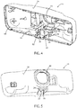
- reference numeral 10 generally designates a rearview mirror 10 useable within a vehicle 12 ( FIG. 3 ).
- the rearview mirror 10 includes a housing 14 defining an interior cavity 16 ( FIG. 4 ) and an opening 18 to an exterior 20 of the housing 14.
- a notch 22 extends from an edge 24 of the opening 18.
- the rearview mirror 10 also includes an actuation mechanism 26 coupled within the interior cavity 16 of the housing 14.
- the actuation mechanism 26 includes a toggle barrel 28 rotatably positioned within the interior cavity 16 of the housing 14 and a lever 30 extending from the toggle barrel 28 through the opening 18.
- the lever 30 defines a first major surface 32 and includes a locking rib 34 extending from the first major surface 32 adjacent the barrel 28.
- the lever 30 is rotatable with corresponding rotation of the toggle barrel 28 with respect to the housing 14 between a first position ( FIG. 1 ) and a second position ( FIG. 2 ).
- the locking rib 34 is positioned within the notch 22 of the housing 14 when the lever 30 and the toggle barrel 28 are in the first position and is positioned away from the notch 22 when the lever 30 and the toggle barrel 28 are in the second position.
- rearview mirror 10 can be used in connection with a vehicle interior 36.
- rearview mirror 10 can be mounted adjacent a windshield 38 of vehicle 12 either by attachment with the windshield 38 itself or to an internal component adjacent headliner 40 (which may include a portion of the vehicle frame, a vehicle panel, or other support structure, for example).
- headliner 40 which may include a portion of the vehicle frame, a vehicle panel, or other support structure, for example.
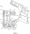
- FIGS. 1-2 and 6-10 such attachment is achieved by a mounting arm 42 that is coupled with vehicle 12, as described, and couples with actuation mechanism 26 (as shown in FIGS. 6-12 ), as explained further below, by extending through an aperture 44 in housing 14.
- actuation mechanism 26 as shown in FIGS. 6-12
- Substrate 46 is generally configured to present an image to a driver of vehicle 12 of the view to the rear of vehicle 12 and, accordingly, may be adjustable by movement of housing 14 about mounting arm 42.
- substrate 46 can include a video display along a portion or an entirety thereof such that rearview mirror 10 is what may be referred to as a full-display mirror.
- Substrate 46 including such a display is referred to herein as "display substrate 46" and may be capable of displaying a mirror-image of the view to the rear of vehicle 12 (that may be captured by an appropriately-positioned video camera or the like) when the display is in an active state.
- Such an image may generally replicate that which would be available from a typical reflective mirror and can be supplemented with other information presented on display substrate 46.
- a reflective surface 49 may be applied so as to overlie the display as a coating or separate element having properties to both provide a reflected image as well as to permit a video image of display substrate 46 to be visible therethrough.
- reflective surface 49 permits substrate 46 to be used as a standard rearview mirror (i.e. without the need to view the displayed image) when the display is inactive, which may occur when the related vehicle 12 is not running or when power to the display substrate 46 is interrupted, for example.
- the presence of the reflective surface 49 over display substrate 46 can cause the image reflected by reflective surface 49 to compete with an image presented on display substrate 46.
- substrate 46 can be positioned such that reflective surface 49 reflects an image of the headliner 40 toward the driver. Because vehicle headliners are of generally consistent, non-reflective material, such an image may compete less with the video image of display substrate 46.
- Rearview mirror 10, by way of the actuation mechanism 26, spring plate 54, and toggle barrel 28 can provide for a user to control repositioning of display substrate 46 between an appropriate position thereof for use of reflective surface 49 when display substrate 46 is in the inactive state and for viewing of a displayed image, without undesirable competition, when display substrate 46 is in the active state.
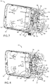
- such movement can be achieved by manipulation of lever 30 between the first position, shown in FIG. 1 , to the second position, shown in FIG. 2 , which can cause actuation mechanism 26 to change from a first stable configuration (as shown in FIG. 7 ) to a second stable configuration (as shown in FIG. 8 ), which in turn causes movement of housing 14 and substrate 46 through a predetermined angle relative to mounting arm 42.
- such movement can be through a downward (i.e. away from headliner 40) angle of between about 5° and 10°, and in one embodiment about 6°.
- mounting arm 42 can couple with actuation mechanism 26 by attachment with a mounting plate 48 thereof by a ball 50 and socket 52 arrangement.
- This arrangement can allow for the above-mentioned general adjustment of substrate 46 so as to position substrate 46 at a desired position with respect to the driver for viewing of the image presented on display substrate 46.
- movement of lever 30 from the first position to the second position can cause movement of housing 14 relative to mounting plate 48, while mounting plate 48 remains generally static.
- substrate 46 can toggle between the positions for substrate 46 provided by the above-referenced stable conditions of actuation mechanism 26 without changing the positions themselves.
- rearview mirror 10 may be a standard mirror, in which substrate 46 is a prism-type mirror substrate 46, which provides for a viewing angle at which substrate 46 reflects the rearward view of mirror 10 with a reduced luminosity to provide a dimming effect useful when driving at night, for example.
- the dimmed viewing angle for substrate 46 may be at a predetermined angle upward (i.e. toward headliner 40) relative to the "normal" viewing angle.
- lever 30 may allow a user to adjust the substrate 46 from the standard viewing mode to the upward, dimmed mode, by movement thereof to change the state of the actuation mechanism 26, without changing the position of substrate 46 in the standard mode and, further, providing for movement into the dimmed mode such that substrate 46 provides generally the same view in the dimmed mode as has been selected for the standard mode.
- the mechanism by which lever 30 repositions substrate 46 may be generally similar in function to known rearview mirror toggle mechanisms with potential modifications to suit, for example, the use to move substrate 46 between the above-described active and passive positions.
- such mechanisms may be susceptible to inadvertent actuation, particularly when in the above-described first position, wherein substrate 46 is angled upwardly toward headliner 40.
- inadvertent actuation may be caused by a user adjusting the position of substrate 46 by grasping and moving housing 14, intending to move housing 14 relative to mounting arm 42 by movement of mounting plate 48 relative thereto.
- housing 14 moves relative to mounting arm 42 in facilitated by the internal components of rearview mirror 10.
- internal components include toggle barrel 28, mounting plate 48, and a spring plate 54 that generally operably couples mounting plate 48 and toggle barrel 28 such that rotation thereof by lever 30 can move housing 14 in a desired rotation thereof about a first end 56 of mounting plate 48.
- Mounting plate 48 can couple a mounting structure 58 within housing 14.
- housing 14 defines an aperture 44 positioned adjacent mounting plate 48 such that mounting arm 42 can pass therethrough, thus allowing mounting plate 48 to couple with mounting arm 42 to retain rearview mirror 10 in an adjustable position with respect to windshield 38 or headliner 40.
- housing 14 With respect to mounting plate 48 causes movement of housing 14 (and accordingly substrate 46 coupled therewith) in the form of rotation thereof about first end 56 of mounting plate 48.
- Such movement moves substrate 46 between the above-described active ( FIG. 1 ) and inactive ( FIG. 2 ) positions.
- orientation can be achieved by rotation of mounting plate 48 with respect to housing 14 through an angle of about 6°, although such an angle can vary based on the location and structure of rearview mirror 10.
- housing 14 and substrate 46 can be achieved by the above-described operative coupling of toggle barrel 28 with spring arms 68.
- rotation of toggle barrel 28, such as by manipulation of lever 30, moves toggle barrel 28 in a generally outward or inward direction with respect to a second end 60 of mounting plate 48, thereby causing rotation of housing 14, within which toggle barrel 28 is rotatably mounted, and substrate 46 about first end 56 of mounting plate 48 upward or downward about mounting structure 58 with which mounting plate 48 is rotatably fixed, as discussed further below.
- housing 14 is shown in the form of a single-piece structure, and can further be made from a single piece of injection molded plastic or the like, although other materials are possible.
- substrate 46 can be coupled with a bezel 62, or other secondary housing piece, that can, in turn, be coupled with housing 14 to fix substrate 46 over an open side 64 of housing 14.
- substrate 46 can be coupled directly to housing 14 over open side 64.
- housing 14 is structured so that interior cavity 16 is of a sufficient depth to retain internal structures thereof, including actuation mechanism 26 ( FIG. 7 ), and other related structures, as well as control circuitry for display substrate 46.
- mounting plate 48 is rotatably coupled with housing 14 at first end 56 thereof.
- Such coupling can be achieved by the incorporation of a first hinge portion 66 into first end 56 of mounting plate 48 and by configuring mounting structure 58 as a mating second hinge portion.
- a separate hinge (not shown) can be coupled between mounting plate 48 and housing 14.
- mounting plate 48 can generally extend through a majority of a vertical height of housing 14.
- toggle barrel 28 It may be desirable to structure toggle barrel 28, spring plate 54 (including spring arms 68, which extend therefrom to couple spring plate 54 with toggle barrel 28), and mounting plate 48 such that, as discussed above, the operable coupling of spring arms 68 with toggle barrel 28 provides two stable positions for toggle barrel 28 that correspond to the first ( FIG. 1 ) and second ( FIG. 2 ) positions for housing 14, which are angularly spaced-apart from each other by angle 70 which may be between about 5° and about 10° (and in an embodiment about 6°). Further, such rotation of housing 14 about mounting plate 48 can be achieved through rotation of toggle barrel 28 through an angle of between about 70° and 100° and in one embodiment about 80°, for example.
- spring arms 68 are coupled with toggle barrel 28 by engagement thereof within slot 74 (further illustrated in FIGS. 11 and 12 ), which is configured so as to receive spring arms 68 (such as by a cradling, snap, or press-fit arrangement) and to maintain a general position thereof that is offset from an axis 76, about which toggle barrel 28 rotates.
- the offset arrangement of slot 74 with respect to axis 76 is such that slot 74 translates in the longitudinal horizontal direction upon rotation of toggle barrel 28 about axis 76.
- This translation causes movement of spring arms 68, which are coupled therewith, resulting in rotation of mounting plate 48 about first end 56.
- Spring arms 68 are of a resiliently deformable material, such as metal (e.g. spring steel, aluminum, or the like), for example, which may be the same as the entirety of spring plate 54 with which spring arms 68 may be integrally joined.
- the resilient deformability of spring arms 68 allows them to accommodate the component movement of slot 74 in the vertical direction during the rotation thereof that results in the aforementioned longitudinal horizontal translation.
- Spring arms 68 can further be tuned to provide the above-noted stable positions for actuation mechanism 26 and, accordingly, rearview mirror 10.
- the resilient deformability of spring arms 68 may be such that spring arms 68 exert a spring force opposing the compression thereof that results from the vertical movement component of slot 74 during rotation of toggle barrel 28 about axis 76, such a force being sufficient to overcome the internal forces of actuation mechanism 26 (e.g. friction between and among the various components thereof) and to urge toggle barrel 28 into either of the positions thereof that are associated with the first position (as shown in FIG. 1 ) and the second position (as shown in FIG. 2 ), upon slot 74 passing a vertical-most position during rotation thereof.
- spring arms 68 can provide a generally vertically-downward force on slot 74 that urges rotation of toggle barrel 28 when slot 74 is on either side of the vertical-most position during rotation thereof, such force urging the actuation mechanism 26 to the nearest stable position.
- Spring arms 68 can, further, be configured so as to be under compression so as to be biased against toggle barrel 28 when actuation mechanism 26 is in either stable position.
- lever 30 is coupled with (and can, further be integrally-formed with) toggle barrel 28 such that the movement of lever 30 from the first position ( FIG. 1 ) to the second position ( FIG. 2 ) causes corresponding movement of toggle barrel 28 and, therefore, the above-described movement of housing 14.
- locking rib 34 extends from first major surface 32 of lever 30 (and may also join with an adjacent portion of toggle barrel 28) such that, when lever 30 and housing 14 are in their respective first positions ( FIGS.
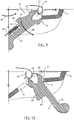
- locking rib 34 extends into notch 22 adjacent the opening 18 through which lever 30 extends. Because movement of actuation mechanism 26 between the first and second stable conditions requires movement of lever 30, inadvertent movement of actuation mechanism 26 out of the first stable condition ( FIG. 7 ) can be resisted or prevented by retaining lever 30 in the first position ( FIG. 9 ). Accordingly, engagement between locking rib 34 and notch 22 can potentially prevent inadvertent actuation of actuation mechanism 26 due to forcible movement of housing 14 when housing 14 is in the first position ( FIG. 1 ).
- toggle barrel 28 is rotatably positioned within housing 14 by being supported on support ribs 78 that are integral with housing 14.
- Each support rib 78 includes an arched cradle portion 80 and an adjacent ramp portion 82.
- the force of spring arms 68 on toggle barrel 28 can maintain toggle barrel 28 in contact with cradle portion 80, including during rotation thereof due to a force applied on lever 30, such as from the first position ( FIG. 9 ) to the second position ( FIG. 10 ).
- a force is applied to housing 14, such as during adjustment of the position and orientation of substrate 46, including force 84, shown in FIG.
- the orientation of ramp portion 82 and/or the tuning of spring arms 68 may allow toggle barrel 28 to move at least partially into ramp portions 82.
- Such movement allows housing 14 to rotate in the direction of force 84 slightly, which causes notch 22 to move in direction 86 and into contact with locking rib 34.
- Such movement can be less than the movement required to rotate toggle barrel 28 to the point that it is urged toward the second stable position ( FIG. 10 ) such that forcible engagement is made between notch 22 and locking rib 34 before inadvertent actuation occurs.
- locking rib 34 may define an undercut 89 (or reverse draft angle) such that when notch 22 moves into contact with locking rib 34 it is at least partially received within undercut 89.
- This configuration contributes to the engagement between notch 22 and locking rib 34, thereby preventing rotation of lever 30 in direction 88 with continued application of force 84.
- application of force 84 causes movement of mounting plate 48 (as shown in FIGS. 6-8 ) about mounting arm 42 and not inadvertent actuation of actuation mechanism 26.
- force 84 ceases (or changes direction)
- the force of spring arms 68 urges toggle barrel 28 back into an equilibrium position within cradle portion 80, thereby urging housing 14 slightly outward (i.e. in the opposite direction of direction 86), allowing notch 22 to disengage from locking rib 34, thereby allowing actuation of actuation mechanism 26 by movement of lever 30.
- notch 22 and locking rib 34 allows for prevention of inadvertent actuation without the use of a mechanism that requires additional force to move lever 30 into and out of the first position ( FIG. 9 ).
- a snap-fit between notch 22 and locking rib 34 may require additional force on lever 30 to overcome the strength of the fit between notch 22 and locking rib 34, which could lead to a failure to engage when lever 30 is moved into the first position or additional force to move out of the first position that could result in inadvertent adjustment of housing 14 with respect to mounting arm 42 by movement of mounting plate 48 with respect thereto.
- FIGS. 13-16 A variation of a combined toggle barrel 128 and lever 130 is illustrated in FIGS. 13-16 .
- damper inserts 190 and 192 are coupled with the body portion of lever 130 in locations where lever 130 contacts housing 114 adjacent the opening 118 through which lever 130 extends.
- one insert 190 is positioned along the first major surface 132 of lever 130 and the second insert 192 is oppositely positioned along a second major surface 194 of lever 130.
- the combined toggle barrel 128 and lever 130 may be of a hard plastic material, such as polycarbonate (“PC”), acrylonitrile butadiene styrene (“ABS”), PC-ABS, or the like.
- Housing 114 may be made of the same material as or a similar material to toggle barrel 128 and lever 130, which may lead to audible clicks or other noises when lever 130 is moved into either the first position ( FIG. 15 ) or second position ( FIG. 16 ).
- inserts 190 and 192 may be of a softer (i.e., lower hardness), resiliently-deformable material such as thermoplastic elastomer ("TPE") or other moldable soft-touch materials.
- TPE thermoplastic elastomer
- inserts 190 and 192 can be insert molded onto or co-molded with the combined toggle barrel 128 and lever 130. In this manner, inserts 190 and 192 can cushion the impact of lever 130 against housing 114 during movement between the first and second positions thereof, which can serve to reduce any audible noise therefrom.
Landscapes
- Engineering & Computer Science (AREA)
- Multimedia (AREA)
- Mechanical Engineering (AREA)
- Rear-View Mirror Devices That Are Mounted On The Exterior Of The Vehicle (AREA)
Description
- The present disclosure relates generally to a mechanism for preventing undesired movement of a rearview mirror assembly for a motor vehicle between use positions. In one aspect, the mechanism may prevent inadvertent movement of a full-display rearview mirror from an active to an inactive position.
-
US 4 826 289 A describes a day/night rearview mirror assembly for vehicles useful in varying climatic conditions which provides improved control and shifting between day and night positions, reduced undesired movement between day and night positions during adjustment of the major mirror position, and improved impact and bending resistance. The assembly preferably includes a molded mirror case, a prismatic mirror element and a two piece actuator assembly which provides consistent day/night shifting pressure in all temperatures. At least one stop member on the case back is included to limit actuator movement and precisely control day/night shifting. Cam surfaces on the actuator and stop member aid assembly. Downwardly opening support members pivotally mount the actuator assembly and prevent actuator movement toward the mirror element even upon impact. Ramp shoulders adjacent the support members also restrict actuator withdrawal. An extending lip on the actuator toggle limits movement of the separate actuator pivot member toward the mirror element upon impact and aids actuator installation. An improved actuator toggle having an integral retainer for a ball joint clamping member is also disclosed. - Vehicle rearview mirrors of the so-called "flipper mirror" type include an actuation mechanism driven by an external lever to move the mirror surface between night and day modes that use different features of the mirror to reflect light at different levels. These actuation mechanisms are configured to be stable in both such positions and otherwise to be urged toward the closest of the stable positions. Known rearview mirror toggle mechanisms may be susceptible to inadvertent actuation, particularly when in the night position, wherein the mirror substrate is angled upwardly toward the vehicle headliner. Such inadvertent actuation may be caused by a user adjusting the position of the substrate by grasping and moving the mirror housing, intending to move the housing relative to an associated mounting structure. During such movement, particular forces can urge the housing toward the opposite stable position with respect to the mounting structure, which may cause such inadvertent actuation of the actuation mechanism and corresponding movement of the housing and, accordingly, the substrate into the opposite stable position. In the case of a standard prism mirror, such inadvertent actuation may be inconvenient.
- According to an aspect of the present disclosure, a rearview mirror for a vehicle includes a housing defining an interior cavity and an opening to an exterior of the housing, a notch extending from an edge of the opening and an actuation mechanism coupled within the interior of the housing. The actuation mechanism has a toggle barrel rotatably positioned within the interior cavity of the housing and a lever extending from the toggle barrel through the opening. The lever defines a first major surface and includes a locking rib extending from the first major surface adjacent the barrel. The lever is rotatable with corresponding rotation of the toggle barrel with respect to the housing between a first position and a second position, the locking rib being positioned within the notch of the housing when the lever and the toggle barrel are in the first position and being positioned away from the notch when the lever and the toggle barrel are in the second position.
- According to another aspect of the disclosure, a vehicle includes a windshield, a headliner adjacent an upper edge of the windshield, and a mirror assembly. The mirror assembly includes a housing defining an interior cavity and an opening to an exterior of the housing, a notch extending from an edge of the opening, and an actuation mechanism coupled within the interior of the housing. The actuation mechanism has a toggle barrel rotatably positioned within the interior cavity of the housing and a lever extending from the toggle barrel through the opening. The lever defines a first major surface and includes a locking rib extending from the first major surface adjacent the barrel. The lever is rotatable with corresponding rotation of the toggle barrel with respect to the housing between a first position and a second position, the locking rib being positioned within the notch of the housing when the lever and the toggle barrel are in the first position and being positioned away from the notch when the lever and the toggle barrel are in the second position.
- These and other features, advantages, and objects of the present device will be further understood and appreciated by those skilled in the art upon studying the following specification, claims, and appended drawings.
- In the drawings:
-
FIG. 1 is a front perspective view of a rearview mirror assembly according to an embodiment of the disclosure in a first state; -
FIG. 2 is a back-lower perspective view of the rearview mirror assembly ofFIG. 1 in a second state; -
FIG. 3 is a perspective view of an interior of a vehicle including the rearview mirror assembly ofFIG. 1 ; -
FIG. 4 is a front perspective view of a housing portion of the rearview mirror assembly ofFIG. 1 ; -
FIG. 5 is a rear perspective view of the housing portion ofFIG. 4 ; -
FIG. 6 is a cross-section view of the rearview mirror assembly ofFIG. 1 , taken along a longitudinal midplane thereof; -
FIG. 7 is a side perspective cross-section view of a portion of the rearview mirror assembly ofFIG. 1 in the first state; -
FIG. 8 is a side perspective cross-section view of the portion of the rearview mirror assembly ofFIG. 7 in the second state; -
FIG. 9 is a cross-sectional detail view of a portion of the rearview mirror assembly ofFIG. 1 in the first state; -
FIG. 10 is a cross-sectional detail view of the portion of the rearview mirror assembly ofFIG. 9 in the second state; -
FIG. 11 is a front perspective view of a part included in the rearview mirror assembly ofFIG. 1 ; -
FIG. 12 is a rear perspective view of the part ofFIG. 11 ; -
FIG. 13 is a front perspective view of a variation of the part ofFIG. 11 useable in a variation of the rearview mirror assembly ofFIG. 1 ; -
FIG. 14 is a rear perspective view of the part ofFIG. 13 ; -
FIG. 15 is a cross-sectional detail view of a portion of a variation of the rearview mirror assembly ofFIG. 1 in the first state including the part ofFIG. 13 ; and -
FIG. 16 is a cross-sectional detail view of the portion of the rearview mirror assembly ofFIG. 15 in a second state. - For purposes of description herein the terms "upper," "lower," "right," "left," "rear," "front," "vertical," "horizontal," and derivatives thereof shall relate to the device as oriented in
FIG. 1 . However, it is to be understood that the device may assume various alternative orientations and step sequences, except where expressly specified to the contrary. It is also to be understood that the specific devices and processes illustrated in the attached drawings, and described in the following specification are simply exemplary embodiments of the inventive concepts defined in the appended claims. Hence, specific dimensions and other physical characteristics relating to the embodiments disclosed herein are not to be considered as limiting, unless the claims expressly state otherwise. - As shown in
FIGS. 1-12 ,reference numeral 10 generally designates arearview mirror 10 useable within a vehicle 12 (FIG. 3 ). Therearview mirror 10 includes ahousing 14 defining an interior cavity 16 (FIG. 4 ) and anopening 18 to anexterior 20 of thehousing 14. Anotch 22 extends from anedge 24 of the opening 18. Therearview mirror 10 also includes anactuation mechanism 26 coupled within theinterior cavity 16 of thehousing 14. Theactuation mechanism 26 includes atoggle barrel 28 rotatably positioned within theinterior cavity 16 of thehousing 14 and alever 30 extending from thetoggle barrel 28 through theopening 18. Thelever 30 defines a firstmajor surface 32 and includes alocking rib 34 extending from the firstmajor surface 32 adjacent thebarrel 28. Thelever 30 is rotatable with corresponding rotation of thetoggle barrel 28 with respect to thehousing 14 between a first position (FIG. 1 ) and a second position (FIG. 2 ). Thelocking rib 34 is positioned within thenotch 22 of thehousing 14 when thelever 30 and thetoggle barrel 28 are in the first position and is positioned away from thenotch 22 when thelever 30 and thetoggle barrel 28 are in the second position. - As shown in
FIG. 3 ,rearview mirror 10 can be used in connection with avehicle interior 36. In particular,rearview mirror 10 can be mounted adjacent awindshield 38 ofvehicle 12 either by attachment with thewindshield 38 itself or to an internal component adjacent headliner 40 (which may include a portion of the vehicle frame, a vehicle panel, or other support structure, for example). As shown further inFIGS. 1-2 and6-10 , such attachment is achieved by amounting arm 42 that is coupled withvehicle 12, as described, and couples with actuation mechanism 26 (as shown inFIGS. 6-12 ), as explained further below, by extending through anaperture 44 inhousing 14.Opposite aperture 44, asubstrate 46 is positioned over anopen side 64 ofhousing 14.Substrate 46 is generally configured to present an image to a driver ofvehicle 12 of the view to the rear ofvehicle 12 and, accordingly, may be adjustable by movement ofhousing 14 about mountingarm 42. In one embodiment,substrate 46 can include a video display along a portion or an entirety thereof such thatrearview mirror 10 is what may be referred to as a full-display mirror.Substrate 46 including such a display is referred to herein as "display substrate 46" and may be capable of displaying a mirror-image of the view to the rear of vehicle 12 (that may be captured by an appropriately-positioned video camera or the like) when the display is in an active state. Such an image may generally replicate that which would be available from a typical reflective mirror and can be supplemented with other information presented ondisplay substrate 46. In combination with such adisplay substrate 46, areflective surface 49 may be applied so as to overlie the display as a coating or separate element having properties to both provide a reflected image as well as to permit a video image ofdisplay substrate 46 to be visible therethrough. - The presence of
reflective surface 49permits substrate 46 to be used as a standard rearview mirror (i.e. without the need to view the displayed image) when the display is inactive, which may occur when therelated vehicle 12 is not running or when power to thedisplay substrate 46 is interrupted, for example. When in the active state, however, the presence of thereflective surface 49 overdisplay substrate 46 can cause the image reflected byreflective surface 49 to compete with an image presented ondisplay substrate 46. To alleviate such image competition,substrate 46 can be positioned such thatreflective surface 49 reflects an image of theheadliner 40 toward the driver. Because vehicle headliners are of generally consistent, non-reflective material, such an image may compete less with the video image ofdisplay substrate 46. -
Rearview mirror 10, by way of theactuation mechanism 26,spring plate 54, and togglebarrel 28 can provide for a user to control repositioning ofdisplay substrate 46 between an appropriate position thereof for use ofreflective surface 49 whendisplay substrate 46 is in the inactive state and for viewing of a displayed image, without undesirable competition, whendisplay substrate 46 is in the active state. As described further, below, such movement can be achieved by manipulation oflever 30 between the first position, shown inFIG. 1 , to the second position, shown inFIG. 2 , which can causeactuation mechanism 26 to change from a first stable configuration (as shown inFIG. 7 ) to a second stable configuration (as shown inFIG. 8 ), which in turn causes movement ofhousing 14 andsubstrate 46 through a predetermined angle relative to mountingarm 42. In an example, such movement can be through a downward (i.e. away from headliner 40) angle of between about 5° and 10°, and in one embodiment about 6°. - As shown in the cross-section views of
FIGS. 6-8 , mountingarm 42 can couple withactuation mechanism 26 by attachment with a mountingplate 48 thereof by aball 50 andsocket 52 arrangement. This arrangement can allow for the above-mentioned general adjustment ofsubstrate 46 so as to positionsubstrate 46 at a desired position with respect to the driver for viewing of the image presented ondisplay substrate 46. As described further below, movement oflever 30 from the first position to the second position, for example, can cause movement ofhousing 14 relative to mountingplate 48, while mountingplate 48 remains generally static. Such a configuration can allowsubstrate 46 to toggle between the positions forsubstrate 46 provided by the above-referenced stable conditions ofactuation mechanism 26 without changing the positions themselves. - In another embodiment,
rearview mirror 10 may be a standard mirror, in whichsubstrate 46 is a prism-type mirror substrate 46, which provides for a viewing angle at whichsubstrate 46 reflects the rearward view ofmirror 10 with a reduced luminosity to provide a dimming effect useful when driving at night, for example. In such an embodiment, the dimmed viewing angle forsubstrate 46 may be at a predetermined angle upward (i.e. toward headliner 40) relative to the "normal" viewing angle. As such,lever 30 may allow a user to adjust thesubstrate 46 from the standard viewing mode to the upward, dimmed mode, by movement thereof to change the state of theactuation mechanism 26, without changing the position ofsubstrate 46 in the standard mode and, further, providing for movement into the dimmed mode such thatsubstrate 46 provides generally the same view in the dimmed mode as has been selected for the standard mode. - In either embodiment, the mechanism by which
lever 30 repositionssubstrate 46 may be generally similar in function to known rearview mirror toggle mechanisms with potential modifications to suit, for example, the use to movesubstrate 46 between the above-described active and passive positions. In general, such mechanisms may be susceptible to inadvertent actuation, particularly when in the above-described first position, whereinsubstrate 46 is angled upwardly towardheadliner 40. Such inadvertent actuation may be caused by a user adjusting the position ofsubstrate 46 by grasping and movinghousing 14, intending to movehousing 14 relative to mountingarm 42 by movement of mountingplate 48 relative thereto. During such movement, particular forces can urgehousing 14 toward the second stable position with respect to mountingplate 48, which may cause such inadvertent actuation ofactuation mechanism 26 and corresponding movement ofhousing 14 and, accordingly,substrate 46 into second position. In the case of a standard prism mirror, such inadvertent actuation may be inconvenient. Further, in the case of a display mirror, as described above, movement out of the first position may trigger deactivation ofdisplay substrate 46, meaning that the desired view fromrearview mirror 10 may change. Accordingly, it may be beneficial to limit inadvertent actuation in either embodiment. - As mentioned above, movement of
housing 14 relative to mountingarm 42 is facilitated by the internal components ofrearview mirror 10. With continued reference toFIGS. 6-8 , such internal components includetoggle barrel 28, mountingplate 48, and aspring plate 54 that generally operablycouples mounting plate 48 andtoggle barrel 28 such that rotation thereof bylever 30 can movehousing 14 in a desired rotation thereof about afirst end 56 of mountingplate 48. Mountingplate 48 can couple a mountingstructure 58 withinhousing 14. As discussed above,housing 14 defines anaperture 44 positioned adjacent mountingplate 48 such that mountingarm 42 can pass therethrough, thus allowing mountingplate 48 to couple with mountingarm 42 to retainrearview mirror 10 in an adjustable position with respect towindshield 38 orheadliner 40. Accordingly, the above-described relative movement ofhousing 14 with respect to mountingplate 48 causes movement of housing 14 (and accordinglysubstrate 46 coupled therewith) in the form of rotation thereof aboutfirst end 56 of mountingplate 48. Such movement, in turn, movessubstrate 46 between the above-described active (FIG. 1 ) and inactive (FIG. 2 ) positions. As mentioned above, such orientation can be achieved by rotation of mountingplate 48 with respect tohousing 14 through an angle of about 6°, although such an angle can vary based on the location and structure ofrearview mirror 10. - As described above, movement of
housing 14 andsubstrate 46 can be achieved by the above-described operative coupling oftoggle barrel 28 withspring arms 68. In this arrangement, rotation oftoggle barrel 28, such as by manipulation oflever 30, movestoggle barrel 28 in a generally outward or inward direction with respect to asecond end 60 of mountingplate 48, thereby causing rotation ofhousing 14, within whichtoggle barrel 28 is rotatably mounted, andsubstrate 46 aboutfirst end 56 of mountingplate 48 upward or downward about mountingstructure 58 with which mountingplate 48 is rotatably fixed, as discussed further below. - As shown in
FIGS. 4 and 5 ,housing 14 is shown in the form of a single-piece structure, and can further be made from a single piece of injection molded plastic or the like, although other materials are possible. As shown inFIG. 1 ,substrate 46 can be coupled with abezel 62, or other secondary housing piece, that can, in turn, be coupled withhousing 14 to fixsubstrate 46 over anopen side 64 ofhousing 14. In another example,substrate 46 can be coupled directly tohousing 14 overopen side 64. In either example,housing 14 is structured so thatinterior cavity 16 is of a sufficient depth to retain internal structures thereof, including actuation mechanism 26 (FIG. 7 ), and other related structures, as well as control circuitry fordisplay substrate 46. - Returning to
FIGS. 7 and 8 , mountingplate 48, as described above, is rotatably coupled withhousing 14 atfirst end 56 thereof. Such coupling can be achieved by the incorporation of afirst hinge portion 66 intofirst end 56 of mountingplate 48 and by configuring mountingstructure 58 as a mating second hinge portion. Alternatively, a separate hinge (not shown) can be coupled between mountingplate 48 andhousing 14. As further shown inFIGS. 4 and 5 , mountingplate 48 can generally extend through a majority of a vertical height ofhousing 14. - It may be desirable to structure
toggle barrel 28, spring plate 54 (includingspring arms 68, which extend therefrom tocouple spring plate 54 with toggle barrel 28), and mountingplate 48 such that, as discussed above, the operable coupling ofspring arms 68 withtoggle barrel 28 provides two stable positions fortoggle barrel 28 that correspond to the first (FIG. 1 ) and second (FIG. 2 ) positions forhousing 14, which are angularly spaced-apart from each other byangle 70 which may be between about 5° and about 10° (and in an embodiment about 6°). Further, such rotation ofhousing 14 about mountingplate 48 can be achieved through rotation oftoggle barrel 28 through an angle of between about 70° and 100° and in one embodiment about 80°, for example. - As discussed previously, the coupling of
spring arms 68 withtoggle barrel 28 can provide both for the desired rotation ofhousing 14 and for the above-noted stable positions. In particular,spring arms 68 are coupled withtoggle barrel 28 by engagement thereof within slot 74 (further illustrated inFIGS. 11 and 12 ), which is configured so as to receive spring arms 68 (such as by a cradling, snap, or press-fit arrangement) and to maintain a general position thereof that is offset from anaxis 76, about whichtoggle barrel 28 rotates. - The offset arrangement of
slot 74 with respect toaxis 76 is such thatslot 74 translates in the longitudinal horizontal direction upon rotation oftoggle barrel 28 aboutaxis 76. This translation causes movement ofspring arms 68, which are coupled therewith, resulting in rotation of mountingplate 48 aboutfirst end 56.Spring arms 68 are of a resiliently deformable material, such as metal (e.g. spring steel, aluminum, or the like), for example, which may be the same as the entirety ofspring plate 54 with which springarms 68 may be integrally joined. The resilient deformability ofspring arms 68 allows them to accommodate the component movement ofslot 74 in the vertical direction during the rotation thereof that results in the aforementioned longitudinal horizontal translation.Spring arms 68 can further be tuned to provide the above-noted stable positions foractuation mechanism 26 and, accordingly,rearview mirror 10. - In particular, the resilient deformability of
spring arms 68 may be such thatspring arms 68 exert a spring force opposing the compression thereof that results from the vertical movement component ofslot 74 during rotation oftoggle barrel 28 aboutaxis 76, such a force being sufficient to overcome the internal forces of actuation mechanism 26 (e.g. friction between and among the various components thereof) and to urgetoggle barrel 28 into either of the positions thereof that are associated with the first position (as shown inFIG. 1 ) and the second position (as shown inFIG. 2 ), uponslot 74 passing a vertical-most position during rotation thereof. In other words,spring arms 68 can provide a generally vertically-downward force onslot 74 that urges rotation oftoggle barrel 28 whenslot 74 is on either side of the vertical-most position during rotation thereof, such force urging theactuation mechanism 26 to the nearest stable position.Spring arms 68 can, further, be configured so as to be under compression so as to be biased againsttoggle barrel 28 whenactuation mechanism 26 is in either stable position. - As illustrated in
FIGS. 1, 2 , and6 , the movement ofhousing 14 between the first (FIG. 1 ) and second (FIG. 2 ) positions byactuation mechanism 26 is achieved by movement oflever 30 from corresponding first and second positions. As shown,lever 30 is coupled with (and can, further be integrally-formed with)toggle barrel 28 such that the movement oflever 30 from the first position (FIG. 1 ) to the second position (FIG. 2 ) causes corresponding movement oftoggle barrel 28 and, therefore, the above-described movement ofhousing 14. As further illustrated inFIGS. 9 and 10 , lockingrib 34 extends from firstmajor surface 32 of lever 30 (and may also join with an adjacent portion of toggle barrel 28) such that, whenlever 30 andhousing 14 are in their respective first positions (FIGS. 1 and9 ), lockingrib 34 extends intonotch 22 adjacent theopening 18 through whichlever 30 extends. Because movement ofactuation mechanism 26 between the first and second stable conditions requires movement oflever 30, inadvertent movement ofactuation mechanism 26 out of the first stable condition (FIG. 7 ) can be resisted or prevented by retaininglever 30 in the first position (FIG. 9 ). Accordingly, engagement between lockingrib 34 and notch 22 can potentially prevent inadvertent actuation ofactuation mechanism 26 due to forcible movement ofhousing 14 whenhousing 14 is in the first position (FIG. 1 ). - With continued reference to
FIGS. 9 and 10 , and additional reference toFIG. 4 , it can be seen thattoggle barrel 28 is rotatably positioned withinhousing 14 by being supported onsupport ribs 78 that are integral withhousing 14. Eachsupport rib 78 includes anarched cradle portion 80 and anadjacent ramp portion 82. During normal use, the force ofspring arms 68 ontoggle barrel 28 can maintaintoggle barrel 28 in contact withcradle portion 80, including during rotation thereof due to a force applied onlever 30, such as from the first position (FIG. 9 ) to the second position (FIG. 10 ). In the event that a force is applied tohousing 14, such as during adjustment of the position and orientation ofsubstrate 46, includingforce 84, shown inFIG. 9 , that corresponds with movement ofhousing 14 in the direction of the second position thereof and that may cause the above-mentioned inadvertent actuation, the orientation oframp portion 82 and/or the tuning ofspring arms 68 may allowtoggle barrel 28 to move at least partially intoramp portions 82. Such movement allowshousing 14 to rotate in the direction offorce 84 slightly, which causesnotch 22 to move indirection 86 and into contact with lockingrib 34. Such movement can be less than the movement required to rotatetoggle barrel 28 to the point that it is urged toward the second stable position (FIG. 10 ) such that forcible engagement is made betweennotch 22 and lockingrib 34 before inadvertent actuation occurs. - As depicted in
FIGS. 9 and11 , lockingrib 34 may define an undercut 89 (or reverse draft angle) such that whennotch 22 moves into contact with lockingrib 34 it is at least partially received within undercut 89. This configuration contributes to the engagement betweennotch 22 and lockingrib 34, thereby preventing rotation oflever 30 in direction 88 with continued application offorce 84. Accordingly, application offorce 84 causes movement of mounting plate 48 (as shown inFIGS. 6-8 ) about mountingarm 42 and not inadvertent actuation ofactuation mechanism 26. Further, whenforce 84 ceases (or changes direction), the force ofspring arms 68 urges togglebarrel 28 back into an equilibrium position withincradle portion 80, thereby urginghousing 14 slightly outward (i.e. in the opposite direction of direction 86), allowingnotch 22 to disengage from lockingrib 34, thereby allowing actuation ofactuation mechanism 26 by movement oflever 30. - The above-described engagement and disengagement of
notch 22 and lockingrib 34 allows for prevention of inadvertent actuation without the use of a mechanism that requires additional force to movelever 30 into and out of the first position (FIG. 9 ). For example, a snap-fit betweennotch 22 and lockingrib 34 may require additional force onlever 30 to overcome the strength of the fit betweennotch 22 and lockingrib 34, which could lead to a failure to engage whenlever 30 is moved into the first position or additional force to move out of the first position that could result in inadvertent adjustment ofhousing 14 with respect to mountingarm 42 by movement of mountingplate 48 with respect thereto. - A variation of a combined
toggle barrel 128 andlever 130 is illustrated inFIGS. 13-16 . In particular, in this variation damper inserts 190 and 192 are coupled with the body portion oflever 130 in locations wherelever 130 contacts housing 114 adjacent theopening 118 through whichlever 130 extends. As shown inFIGS. 13-16 , oneinsert 190 is positioned along the firstmajor surface 132 oflever 130 and thesecond insert 192 is oppositely positioned along a secondmajor surface 194 oflever 130. In an example, the combinedtoggle barrel 128 andlever 130 may be of a hard plastic material, such as polycarbonate ("PC"), acrylonitrile butadiene styrene ("ABS"), PC-ABS, or the like.Housing 114 may be made of the same material as or a similar material to togglebarrel 128 andlever 130, which may lead to audible clicks or other noises whenlever 130 is moved into either the first position (FIG. 15 ) or second position (FIG. 16 ). Accordingly, inserts 190 and 192 may be of a softer (i.e., lower hardness), resiliently-deformable material such as thermoplastic elastomer ("TPE") or other moldable soft-touch materials. In an embodiment, inserts 190 and 192 can be insert molded onto or co-molded with the combinedtoggle barrel 128 andlever 130. In this manner, inserts 190 and 192 can cushion the impact oflever 130 againsthousing 114 during movement between the first and second positions thereof, which can serve to reduce any audible noise therefrom. - It will be understood that any described processes or steps within described processes may be combined with other disclosed processes or steps to form structures within the scope of the present device. The exemplary structures and processes disclosed herein are for illustrative purposes and are not to be construed as limiting.
- It is also to be understood that variations and modifications can be made on the aforementioned structures and methods without departing from the concepts of the present device, and further it is to be understood that such concepts are intended to be covered by the following claims unless these claims by their language expressly state otherwise.
- The above description is considered that of the illustrated embodiments only. Modifications of the device will occur to those skilled in the art and to those who make or use the device. Therefore, it is understood that the embodiments shown in the drawings and described above is merely for illustrative purposes and not intended to limit the scope of the device, which is defined by the following claims as interpreted according to the principles of patent law, including the Doctrine of Equivalents.
Claims (15)
- A rearview mirror (10) for a vehicle, comprising:a housing (14) defining an interior and an opening (18) to an exterior of the housing (14), a notch (22) extending from an edge (24) of the opening (18); andan actuation mechanism (26) coupled within the interior of the housing (14) and including:a toggle barrel (28) rotatably positioned within the interior cavity (16) of the housing (14); anda lever (30) extending from the toggle barrel (28) through the opening (18), the lever (30) defining a first major surface (32) and including a locking rib (34) extending from the first major surface (32) adjacent the barrel (28), the lever (30) being rotatable with corresponding rotation of the toggle barrel (28) with respect to the housing (14) between a first position and a second position, the locking rib (34) being positioned within the notch (22) of the housing (14) when the lever (30) and the toggle barrel (28) are in the first position and being positioned away from the notch (22) when the lever (30) and the toggle barrel (28) are in the second position.
- The rearview mirror (10) of claim 1, wherein:the actuation mechanism (26) further includes a mounting plate (48) rotatably coupled within the cavity (16) of the housing (14) at a first end (56) thereof; andthe toggle barrel (28) is operatively coupled with the mounting plate (48) such that rotation of the toggle barrel (28) between the first position and the second position rotates the housing (14) about the first end (56) of the mounting plate (48) between first and second stable positions respectively corresponding with the first and second positions of the toggle barrel (28).
- The rearview mirror (10) of claim 2, wherein the actuation mechanism (26) further includes a spring plate (54) coupled with the mounting plate (48) and having a resiliently deformable arm (68) extending away from the mounting plate (48), the arm portion of the spring plate (54) operably coupling the mounting plate (48) with the toggle barrel (28).
- The rearview mirror (10) of claim 3, wherein the arm (68) is biased against the toggle barrel (28) to urge the toggle barrel (28) toward a nearest of the first and second positions.
- The rearview mirror (10) of any of claims 2-4, wherein the first and second stable positions are rotationally spaced about the first end (56) of the mounting plate (48) at an angle of between 5 degrees and 10 degrees.
- The rearview mirror (10) of any of claims 2-5, further including a mounting arm (42) coupled with the mounting plate (48), wherein:
the housing (14) defines an aperture (44), the mounting arm (42) extending through the aperture (44) to an exterior of the housing (14). - The rearview mirror (10) of any of the preceding claims, wherein the locking rib (34) forcibly engages with the notch (22) when the lever (30) is in the first position thereby resisting movement of the lever (30) out of the first position.
- The rearview mirror (10) of claim 7, wherein the locking rib (34) defines an undercut (89) including a surface angled towards the first major surface (32), the undercut (89) receiving a portion of the notch (22) therein when the lever (30) is in the first position to contribute to rib forcibly engaging with the notch (22).
- The rearview mirror (10) of any of the preceding claims, wherein the lever (30) includes:a body, the first major surface (32) and the rib (34) being defined on the body; anda first damper along a portion of the first major surface (32).
- The rearview mirror (10) of claim 9, wherein:the body further defines a second major surface opposite the first surface; andthe lever (30) further includes a second damper along a portion of the second major surface.
- The rearview mirror (10) of claim 10, wherein:the body portion is of a first material having a first hardness; andthe first and second damper portions are of a second material having a second hardness that is less than the first hardness.
- The rearview mirror (10) of claim 10 or 11, wherein:the body portion defines an aperture (44) therethrough; andthe first and second damper portions are integrally joined through the aperture (44).
- The rearview mirror (10) of any of the preceding claims, wherein:the interior of the housing (14) defines a support rib (34) having a cradle portion and a ramp portion; andthe toggle barrel (28) is rotatably positioned within the housing (14) by operative engagement with the support rib (34) such that, during rotation of the toggle barrel (28) between the first and second positions by movement of the lever (30), the toggle barrel (28) is positioned within the cradle portion and, when the toggle barrel (28) is in the first position, a force applied on the housing (14) moves the toggle barrel (28) at least partially into the ramp portion, thereby moving the locking rib (34) into contact with a portion of the notch (22).
- The rearview mirror (10) of any of the preceding claims, further including a display substrate (46) coupled over the open side (64) of the housing (14) and having a reflective surface (49) thereon.
- A vehicle (12), comprising:a windshield (38);a headliner (40) adjacent an upper edge (24) of the windshield (38); andthe rearview mirror (10) assembly of any of the preceding claims mounted with one of the windshield (38) or a body of the vehicle (12) adjacent the headliner (40).
Applications Claiming Priority (2)
| Application Number | Priority Date | Filing Date | Title |
|---|---|---|---|
| US201662279144P | 2016-01-15 | 2016-01-15 | |
| PCT/US2017/013333 WO2017123868A1 (en) | 2016-01-15 | 2017-01-13 | Toggle switch lock and cushioned toggle switch for fdm |
Publications (3)
| Publication Number | Publication Date |
|---|---|
| EP3402696A4 EP3402696A4 (en) | 2018-11-21 |
| EP3402696A1 EP3402696A1 (en) | 2018-11-21 |
| EP3402696B1 true EP3402696B1 (en) | 2019-12-04 |
Family
ID=59311489
Family Applications (1)
| Application Number | Title | Priority Date | Filing Date |
|---|---|---|---|
| EP17738999.6A Active EP3402696B1 (en) | 2016-01-15 | 2017-01-13 | Toggle switch lock and cushioned toggle switch for fdm |
Country Status (6)
| Country | Link |
|---|---|
| US (1) | US10464485B2 (en) |
| EP (1) | EP3402696B1 (en) |
| JP (1) | JP6663025B2 (en) |
| KR (1) | KR102003863B1 (en) |
| CN (1) | CN108473091B (en) |
| WO (1) | WO2017123868A1 (en) |
Families Citing this family (2)
| Publication number | Priority date | Publication date | Assignee | Title |
|---|---|---|---|---|
| WO2018057603A1 (en) * | 2016-09-22 | 2018-03-29 | Gentex Corporation | Mirror flipper assembly |
| KR102273674B1 (en) * | 2017-03-09 | 2021-07-05 | 젠텍스 코포레이션 | Display Mirror Toggle Paddle |
Family Cites Families (28)
| Publication number | Priority date | Publication date | Assignee | Title |
|---|---|---|---|---|
| US3421728A (en) | 1966-03-01 | 1969-01-14 | Norman Gordon | Adjustable mirror |
| US3522987A (en) * | 1967-10-09 | 1970-08-04 | Libbey Owens Ford Glass Co | Multiple position rear view mirror |
| JPS61103636A (en) | 1984-10-26 | 1986-05-22 | Hokusei Alum Kk | Method for forming uneven pattern on surface of aluminum or aluminum alloy extrusion hollow forming material |
| JPS61103636U (en) * | 1984-12-13 | 1986-07-01 | ||
| GB8510042D0 (en) | 1985-04-19 | 1985-05-30 | Britax Wingard Ltd | Anti-glare mirror |
| NL8700878A (en) | 1987-04-14 | 1988-11-01 | Iku Holding Montfoort Bv | ADJUSTMENT INSTRUMENT FOR ELECTRICAL ADJUSTMENT OF THE INTERIOR MIRROR OF A MOTOR VEHICLE FOR TWO-MATCH LEAD AXLES. |
| US4826289A (en) * | 1987-09-03 | 1989-05-02 | Donnelly Corporation | Day/night rearview mirror assembly |
| JP2533959Y2 (en) * | 1990-06-30 | 1997-04-30 | 市光工業株式会社 | Anti-glare mirror for automobile |
| JPH0546581U (en) * | 1991-11-27 | 1993-06-22 | 三菱自動車工業株式会社 | Anti-glare mirror |
| US5634859A (en) * | 1995-09-12 | 1997-06-03 | Lisco, Inc. | Grip with increased soft feel and tackiness with decreased torque |
| KR19980036682U (en) | 1996-12-16 | 1998-09-15 | 김영귀 | Room mirror structure of car |
| US5969870A (en) | 1997-09-18 | 1999-10-19 | Anvik Corporation | Remotely adjustable, anti-glare vehicle mirror system |
| US5971550A (en) * | 1998-01-12 | 1999-10-26 | Ford Global Technologies, Inc. | Automotive return rear view mirror |
| JP2001018718A (en) * | 1999-07-12 | 2001-01-23 | Murakami Corp | Rear-view mirror |
| DE29914501U1 (en) | 1999-08-18 | 1999-10-21 | Reitter & Schefenacker Gmbh | Interior rear view mirror for vehicles |
| US6318870B1 (en) * | 2000-03-23 | 2001-11-20 | Donnelly Corporation | Toggle assembly for rearview mirror |
| US7255451B2 (en) | 2002-09-20 | 2007-08-14 | Donnelly Corporation | Electro-optic mirror cell |
| JP4598998B2 (en) | 2001-07-12 | 2010-12-15 | 株式会社村上開明堂 | Manufacturing method of anti-glare mirror for vehicle |
| JP4089224B2 (en) | 2001-12-26 | 2008-05-28 | 市光工業株式会社 | Inside mirror for vehicle |
| US6682122B1 (en) * | 2002-11-22 | 2004-01-27 | Ford Global Technologies, Llc | Supplemental sun visor system for automotive vehicle |
| KR100521682B1 (en) | 2003-09-19 | 2005-10-17 | 현대자동차주식회사 | Inside rear view mirror for automobile |
| US6932484B2 (en) | 2003-09-26 | 2005-08-23 | Dale E. Brandt | Rear view mirror assembly |
| DE102004022523A1 (en) | 2004-05-05 | 2005-12-01 | Donnelly Hohe Gmbh & Co. Kg | Interior mirror with drive device for adjusting a wedge mirror glass |
| JP2006103621A (en) | 2004-10-08 | 2006-04-20 | Ichikoh Ind Ltd | Inside mirror device for vehicle of glare shield type |
| US7722199B2 (en) | 2006-08-23 | 2010-05-25 | Donnelly Corporation | Vehicle interior rearview mirror assembly with actuator |
| EP2422227B1 (en) * | 2009-04-23 | 2014-05-14 | Magna Mirrors Of America, Inc. | Mirror assembly for vehicle |
| EP2789505B1 (en) * | 2011-12-09 | 2017-06-28 | Nissan Motor Company, Limited | Video display mirror and video display mirror system |
| CN105555612B (en) * | 2013-09-24 | 2018-06-01 | 金泰克斯公司 | Show mirror assembly |
-
2017
- 2017-01-13 CN CN201780005138.2A patent/CN108473091B/en active Active
- 2017-01-13 US US15/405,484 patent/US10464485B2/en active Active
- 2017-01-13 JP JP2018536505A patent/JP6663025B2/en active Active
- 2017-01-13 WO PCT/US2017/013333 patent/WO2017123868A1/en active Application Filing
- 2017-01-13 EP EP17738999.6A patent/EP3402696B1/en active Active
- 2017-01-13 KR KR1020187018709A patent/KR102003863B1/en active IP Right Grant
Non-Patent Citations (1)
| Title |
|---|
| None * |
Also Published As
| Publication number | Publication date |
|---|---|
| EP3402696A4 (en) | 2018-11-21 |
| WO2017123868A1 (en) | 2017-07-20 |
| KR102003863B1 (en) | 2019-07-25 |
| JP6663025B2 (en) | 2020-03-11 |
| CN108473091A (en) | 2018-08-31 |
| EP3402696A1 (en) | 2018-11-21 |
| US10464485B2 (en) | 2019-11-05 |
| KR20180088719A (en) | 2018-08-06 |
| JP2019501828A (en) | 2019-01-24 |
| US20170203694A1 (en) | 2017-07-20 |
| CN108473091B (en) | 2021-06-15 |
Similar Documents
| Publication | Publication Date | Title |
|---|---|---|
| US9718409B2 (en) | Full display mirror with worm gear driven toggle mechanism | |
| US10207647B2 (en) | Full display mirror with gear-driven toggle mechanism | |
| US20020096892A1 (en) | Locking apparatus and storage apparatus for vehicle | |
| CN107000642B (en) | Full display mirror actuator | |
| EP3592607B1 (en) | Display mirror toggle paddle | |
| EP3402696B1 (en) | Toggle switch lock and cushioned toggle switch for fdm | |
| EP3494011B1 (en) | Cam-driven toggle switch for mirror assembly | |
| US10506166B2 (en) | Full display mirror actuator with linkage arm | |
| US10596968B2 (en) | Prism toggle spring | |
| US10464488B2 (en) | Mirror flipper assembly | |
| US6168277B1 (en) | Rearview mirror | |
| EP3565738B1 (en) | Mechanical tilt for full display mirror | |
| JP3190286B2 (en) | Hinge | |
| US20060185970A1 (en) | Vehicle latch arrangement | |
| WO2006038273A1 (en) | Vehicle outer mirror |
Legal Events
| Date | Code | Title | Description |
|---|---|---|---|
| STAA | Information on the status of an ep patent application or granted ep patent |
Free format text: STATUS: THE INTERNATIONAL PUBLICATION HAS BEEN MADE |
|
| PUAI | Public reference made under article 153(3) epc to a published international application that has entered the european phase |
Free format text: ORIGINAL CODE: 0009012 |
|
| STAA | Information on the status of an ep patent application or granted ep patent |
Free format text: STATUS: REQUEST FOR EXAMINATION WAS MADE |
|
| 17P | Request for examination filed |
Effective date: 20180628 |
|
| A4 | Supplementary search report drawn up and despatched |
Effective date: 20181004 |
|
| AK | Designated contracting states |
Kind code of ref document: A1 Designated state(s): AL AT BE BG CH CY CZ DE DK EE ES FI FR GB GR HR HU IE IS IT LI LT LU LV MC MK MT NL NO PL PT RO RS SE SI SK SM TR |
|
| AX | Request for extension of the european patent |
Extension state: BA ME |
|
| DAV | Request for validation of the european patent (deleted) | ||
| DAX | Request for extension of the european patent (deleted) | ||
| GRAP | Despatch of communication of intention to grant a patent |
Free format text: ORIGINAL CODE: EPIDOSNIGR1 |
|
| STAA | Information on the status of an ep patent application or granted ep patent |
Free format text: STATUS: GRANT OF PATENT IS INTENDED |
|
| INTG | Intention to grant announced |
Effective date: 20190627 |
|
| GRAS | Grant fee paid |
Free format text: ORIGINAL CODE: EPIDOSNIGR3 |
|
| GRAA | (expected) grant |
Free format text: ORIGINAL CODE: 0009210 |
|
| STAA | Information on the status of an ep patent application or granted ep patent |
Free format text: STATUS: THE PATENT HAS BEEN GRANTED |
|
| AK | Designated contracting states |
Kind code of ref document: B1 Designated state(s): AL AT BE BG CH CY CZ DE DK EE ES FI FR GB GR HR HU IE IS IT LI LT LU LV MC MK MT NL NO PL PT RO RS SE SI SK SM TR |
|
| REG | Reference to a national code |
Ref country code: GB Ref legal event code: FG4D |
|
| REG | Reference to a national code |
Ref country code: CH Ref legal event code: EP |
|
| REG | Reference to a national code |
Ref country code: AT Ref legal event code: REF Ref document number: 1208993 Country of ref document: AT Kind code of ref document: T Effective date: 20191215 |
|
| REG | Reference to a national code |
Ref country code: DE Ref legal event code: R096 Ref document number: 602017009438 Country of ref document: DE |
|
| REG | Reference to a national code |
Ref country code: IE Ref legal event code: FG4D |
|
| REG | Reference to a national code |
Ref country code: NL Ref legal event code: MP Effective date: 20191204 |
|
| REG | Reference to a national code |
Ref country code: LT Ref legal event code: MG4D |
|
| PG25 | Lapsed in a contracting state [announced via postgrant information from national office to epo] |
Ref country code: FI Free format text: LAPSE BECAUSE OF FAILURE TO SUBMIT A TRANSLATION OF THE DESCRIPTION OR TO PAY THE FEE WITHIN THE PRESCRIBED TIME-LIMIT Effective date: 20191204 Ref country code: BG Free format text: LAPSE BECAUSE OF FAILURE TO SUBMIT A TRANSLATION OF THE DESCRIPTION OR TO PAY THE FEE WITHIN THE PRESCRIBED TIME-LIMIT Effective date: 20200304 Ref country code: GR Free format text: LAPSE BECAUSE OF FAILURE TO SUBMIT A TRANSLATION OF THE DESCRIPTION OR TO PAY THE FEE WITHIN THE PRESCRIBED TIME-LIMIT Effective date: 20200305 Ref country code: NO Free format text: LAPSE BECAUSE OF FAILURE TO SUBMIT A TRANSLATION OF THE DESCRIPTION OR TO PAY THE FEE WITHIN THE PRESCRIBED TIME-LIMIT Effective date: 20200304 Ref country code: SE Free format text: LAPSE BECAUSE OF FAILURE TO SUBMIT A TRANSLATION OF THE DESCRIPTION OR TO PAY THE FEE WITHIN THE PRESCRIBED TIME-LIMIT Effective date: 20191204 Ref country code: LV Free format text: LAPSE BECAUSE OF FAILURE TO SUBMIT A TRANSLATION OF THE DESCRIPTION OR TO PAY THE FEE WITHIN THE PRESCRIBED TIME-LIMIT Effective date: 20191204 Ref country code: LT Free format text: LAPSE BECAUSE OF FAILURE TO SUBMIT A TRANSLATION OF THE DESCRIPTION OR TO PAY THE FEE WITHIN THE PRESCRIBED TIME-LIMIT Effective date: 20191204 |
|
| PG25 | Lapsed in a contracting state [announced via postgrant information from national office to epo] |
Ref country code: HR Free format text: LAPSE BECAUSE OF FAILURE TO SUBMIT A TRANSLATION OF THE DESCRIPTION OR TO PAY THE FEE WITHIN THE PRESCRIBED TIME-LIMIT Effective date: 20191204 Ref country code: RS Free format text: LAPSE BECAUSE OF FAILURE TO SUBMIT A TRANSLATION OF THE DESCRIPTION OR TO PAY THE FEE WITHIN THE PRESCRIBED TIME-LIMIT Effective date: 20191204 |
|
| PG25 | Lapsed in a contracting state [announced via postgrant information from national office to epo] |
Ref country code: AL Free format text: LAPSE BECAUSE OF FAILURE TO SUBMIT A TRANSLATION OF THE DESCRIPTION OR TO PAY THE FEE WITHIN THE PRESCRIBED TIME-LIMIT Effective date: 20191204 |
|
| PG25 | Lapsed in a contracting state [announced via postgrant information from national office to epo] |
Ref country code: EE Free format text: LAPSE BECAUSE OF FAILURE TO SUBMIT A TRANSLATION OF THE DESCRIPTION OR TO PAY THE FEE WITHIN THE PRESCRIBED TIME-LIMIT Effective date: 20191204 Ref country code: NL Free format text: LAPSE BECAUSE OF FAILURE TO SUBMIT A TRANSLATION OF THE DESCRIPTION OR TO PAY THE FEE WITHIN THE PRESCRIBED TIME-LIMIT Effective date: 20191204 Ref country code: PT Free format text: LAPSE BECAUSE OF FAILURE TO SUBMIT A TRANSLATION OF THE DESCRIPTION OR TO PAY THE FEE WITHIN THE PRESCRIBED TIME-LIMIT Effective date: 20200429 Ref country code: RO Free format text: LAPSE BECAUSE OF FAILURE TO SUBMIT A TRANSLATION OF THE DESCRIPTION OR TO PAY THE FEE WITHIN THE PRESCRIBED TIME-LIMIT Effective date: 20191204 Ref country code: CZ Free format text: LAPSE BECAUSE OF FAILURE TO SUBMIT A TRANSLATION OF THE DESCRIPTION OR TO PAY THE FEE WITHIN THE PRESCRIBED TIME-LIMIT Effective date: 20191204 Ref country code: ES Free format text: LAPSE BECAUSE OF FAILURE TO SUBMIT A TRANSLATION OF THE DESCRIPTION OR TO PAY THE FEE WITHIN THE PRESCRIBED TIME-LIMIT Effective date: 20191204 |
|
| PG25 | Lapsed in a contracting state [announced via postgrant information from national office to epo] |
Ref country code: SM Free format text: LAPSE BECAUSE OF FAILURE TO SUBMIT A TRANSLATION OF THE DESCRIPTION OR TO PAY THE FEE WITHIN THE PRESCRIBED TIME-LIMIT Effective date: 20191204 Ref country code: SK Free format text: LAPSE BECAUSE OF FAILURE TO SUBMIT A TRANSLATION OF THE DESCRIPTION OR TO PAY THE FEE WITHIN THE PRESCRIBED TIME-LIMIT Effective date: 20191204 Ref country code: IS Free format text: LAPSE BECAUSE OF FAILURE TO SUBMIT A TRANSLATION OF THE DESCRIPTION OR TO PAY THE FEE WITHIN THE PRESCRIBED TIME-LIMIT Effective date: 20200404 |
|
| REG | Reference to a national code |
Ref country code: CH Ref legal event code: PL |
|
| REG | Reference to a national code |
Ref country code: DE Ref legal event code: R097 Ref document number: 602017009438 Country of ref document: DE |
|
| REG | Reference to a national code |
Ref country code: AT Ref legal event code: MK05 Ref document number: 1208993 Country of ref document: AT Kind code of ref document: T Effective date: 20191204 |
|
| PG25 | Lapsed in a contracting state [announced via postgrant information from national office to epo] |
Ref country code: MC Free format text: LAPSE BECAUSE OF FAILURE TO SUBMIT A TRANSLATION OF THE DESCRIPTION OR TO PAY THE FEE WITHIN THE PRESCRIBED TIME-LIMIT Effective date: 20191204 |
|
| PLBE | No opposition filed within time limit |
Free format text: ORIGINAL CODE: 0009261 |
|
| STAA | Information on the status of an ep patent application or granted ep patent |
Free format text: STATUS: NO OPPOSITION FILED WITHIN TIME LIMIT |
|
| REG | Reference to a national code |
Ref country code: BE Ref legal event code: MM Effective date: 20200131 |
|
| PG25 | Lapsed in a contracting state [announced via postgrant information from national office to epo] |
Ref country code: LU Free format text: LAPSE BECAUSE OF NON-PAYMENT OF DUE FEES Effective date: 20200113 Ref country code: DK Free format text: LAPSE BECAUSE OF FAILURE TO SUBMIT A TRANSLATION OF THE DESCRIPTION OR TO PAY THE FEE WITHIN THE PRESCRIBED TIME-LIMIT Effective date: 20191204 |
|
| 26N | No opposition filed |
Effective date: 20200907 |
|
| PG25 | Lapsed in a contracting state [announced via postgrant information from national office to epo] |
Ref country code: LI Free format text: LAPSE BECAUSE OF NON-PAYMENT OF DUE FEES Effective date: 20200131 Ref country code: CH Free format text: LAPSE BECAUSE OF NON-PAYMENT OF DUE FEES Effective date: 20200131 Ref country code: AT Free format text: LAPSE BECAUSE OF FAILURE TO SUBMIT A TRANSLATION OF THE DESCRIPTION OR TO PAY THE FEE WITHIN THE PRESCRIBED TIME-LIMIT Effective date: 20191204 Ref country code: PL Free format text: LAPSE BECAUSE OF FAILURE TO SUBMIT A TRANSLATION OF THE DESCRIPTION OR TO PAY THE FEE WITHIN THE PRESCRIBED TIME-LIMIT Effective date: 20191204 Ref country code: SI Free format text: LAPSE BECAUSE OF FAILURE TO SUBMIT A TRANSLATION OF THE DESCRIPTION OR TO PAY THE FEE WITHIN THE PRESCRIBED TIME-LIMIT Effective date: 20191204 Ref country code: BE Free format text: LAPSE BECAUSE OF NON-PAYMENT OF DUE FEES Effective date: 20200131 |
|
| PG25 | Lapsed in a contracting state [announced via postgrant information from national office to epo] |
Ref country code: IT Free format text: LAPSE BECAUSE OF FAILURE TO SUBMIT A TRANSLATION OF THE DESCRIPTION OR TO PAY THE FEE WITHIN THE PRESCRIBED TIME-LIMIT Effective date: 20191204 Ref country code: IE Free format text: LAPSE BECAUSE OF NON-PAYMENT OF DUE FEES Effective date: 20200113 |
|
| PG25 | Lapsed in a contracting state [announced via postgrant information from national office to epo] |
Ref country code: TR Free format text: LAPSE BECAUSE OF FAILURE TO SUBMIT A TRANSLATION OF THE DESCRIPTION OR TO PAY THE FEE WITHIN THE PRESCRIBED TIME-LIMIT Effective date: 20191204 Ref country code: MT Free format text: LAPSE BECAUSE OF FAILURE TO SUBMIT A TRANSLATION OF THE DESCRIPTION OR TO PAY THE FEE WITHIN THE PRESCRIBED TIME-LIMIT Effective date: 20191204 Ref country code: CY Free format text: LAPSE BECAUSE OF FAILURE TO SUBMIT A TRANSLATION OF THE DESCRIPTION OR TO PAY THE FEE WITHIN THE PRESCRIBED TIME-LIMIT Effective date: 20191204 |
|
| PG25 | Lapsed in a contracting state [announced via postgrant information from national office to epo] |
Ref country code: MK Free format text: LAPSE BECAUSE OF FAILURE TO SUBMIT A TRANSLATION OF THE DESCRIPTION OR TO PAY THE FEE WITHIN THE PRESCRIBED TIME-LIMIT Effective date: 20191204 |
|
| P01 | Opt-out of the competence of the unified patent court (upc) registered |
Effective date: 20230503 |
|
| PGFP | Annual fee paid to national office [announced via postgrant information from national office to epo] |
Ref country code: GB Payment date: 20231219 Year of fee payment: 8 |
|
| PGFP | Annual fee paid to national office [announced via postgrant information from national office to epo] |
Ref country code: FR Payment date: 20231219 Year of fee payment: 8 |
|
| PGFP | Annual fee paid to national office [announced via postgrant information from national office to epo] |
Ref country code: DE Payment date: 20231219 Year of fee payment: 8 |