EP3402632B1 - Détermination d'une orientation d'un robot par rapport à la direction de la gravité - Google Patents
Détermination d'une orientation d'un robot par rapport à la direction de la gravité Download PDFInfo
- Publication number
- EP3402632B1 EP3402632B1 EP17700261.5A EP17700261A EP3402632B1 EP 3402632 B1 EP3402632 B1 EP 3402632B1 EP 17700261 A EP17700261 A EP 17700261A EP 3402632 B1 EP3402632 B1 EP 3402632B1
- Authority
- EP
- European Patent Office
- Prior art keywords
- robot
- model
- orientation
- gravity
- relative
- Prior art date
- Legal status (The legal status is an assumption and is not a legal conclusion. Google has not performed a legal analysis and makes no representation as to the accuracy of the status listed.)
- Active
Links
- 230000005484 gravity Effects 0.000 title claims description 75
- 238000012937 correction Methods 0.000 claims description 56
- 238000000034 method Methods 0.000 claims description 35
- 238000009434 installation Methods 0.000 claims description 26
- 230000033001 locomotion Effects 0.000 claims description 20
- 230000001419 dependent effect Effects 0.000 claims description 5
- 238000004590 computer program Methods 0.000 claims description 4
- 238000011161 development Methods 0.000 description 20
- 230000018109 developmental process Effects 0.000 description 20
- 238000012986 modification Methods 0.000 description 5
- 230000004048 modification Effects 0.000 description 5
- 238000001514 detection method Methods 0.000 description 4
- 230000001066 destructive effect Effects 0.000 description 3
- 230000000694 effects Effects 0.000 description 3
- 230000008569 process Effects 0.000 description 3
- 230000001133 acceleration Effects 0.000 description 2
- 230000001276 controlling effect Effects 0.000 description 2
- 238000013461 design Methods 0.000 description 2
- 239000012636 effector Substances 0.000 description 2
- 230000006870 function Effects 0.000 description 2
- 239000011159 matrix material Substances 0.000 description 2
- 230000009467 reduction Effects 0.000 description 2
- 230000003068 static effect Effects 0.000 description 2
- 238000012935 Averaging Methods 0.000 description 1
- 230000009471 action Effects 0.000 description 1
- 238000005259 measurement Methods 0.000 description 1
- 239000000203 mixture Substances 0.000 description 1
- 230000003287 optical effect Effects 0.000 description 1
- 230000000737 periodic effect Effects 0.000 description 1
- 238000012545 processing Methods 0.000 description 1
- 230000001105 regulatory effect Effects 0.000 description 1
Images
Classifications
-
- B—PERFORMING OPERATIONS; TRANSPORTING
- B25—HAND TOOLS; PORTABLE POWER-DRIVEN TOOLS; MANIPULATORS
- B25J—MANIPULATORS; CHAMBERS PROVIDED WITH MANIPULATION DEVICES
- B25J9/00—Programme-controlled manipulators
- B25J9/16—Programme controls
- B25J9/1628—Programme controls characterised by the control loop
- B25J9/1638—Programme controls characterised by the control loop compensation for arm bending/inertia, pay load weight/inertia
-
- B—PERFORMING OPERATIONS; TRANSPORTING
- B25—HAND TOOLS; PORTABLE POWER-DRIVEN TOOLS; MANIPULATORS
- B25J—MANIPULATORS; CHAMBERS PROVIDED WITH MANIPULATION DEVICES
- B25J9/00—Programme-controlled manipulators
- B25J9/16—Programme controls
- B25J9/1656—Programme controls characterised by programming, planning systems for manipulators
- B25J9/1664—Programme controls characterised by programming, planning systems for manipulators characterised by motion, path, trajectory planning
-
- B—PERFORMING OPERATIONS; TRANSPORTING
- B25—HAND TOOLS; PORTABLE POWER-DRIVEN TOOLS; MANIPULATORS
- B25J—MANIPULATORS; CHAMBERS PROVIDED WITH MANIPULATION DEVICES
- B25J13/00—Controls for manipulators
- B25J13/08—Controls for manipulators by means of sensing devices, e.g. viewing or touching devices
- B25J13/085—Force or torque sensors
-
- B—PERFORMING OPERATIONS; TRANSPORTING
- B25—HAND TOOLS; PORTABLE POWER-DRIVEN TOOLS; MANIPULATORS
- B25J—MANIPULATORS; CHAMBERS PROVIDED WITH MANIPULATION DEVICES
- B25J9/00—Programme-controlled manipulators
- B25J9/16—Programme controls
- B25J9/1679—Programme controls characterised by the tasks executed
- B25J9/1692—Calibration of manipulator
-
- B—PERFORMING OPERATIONS; TRANSPORTING
- B25—HAND TOOLS; PORTABLE POWER-DRIVEN TOOLS; MANIPULATORS
- B25J—MANIPULATORS; CHAMBERS PROVIDED WITH MANIPULATION DEVICES
- B25J9/00—Programme-controlled manipulators
- B25J9/16—Programme controls
- B25J9/1694—Programme controls characterised by use of sensors other than normal servo-feedback from position, speed or acceleration sensors, perception control, multi-sensor controlled systems, sensor fusion
-
- G—PHYSICS
- G05—CONTROLLING; REGULATING
- G05B—CONTROL OR REGULATING SYSTEMS IN GENERAL; FUNCTIONAL ELEMENTS OF SUCH SYSTEMS; MONITORING OR TESTING ARRANGEMENTS FOR SUCH SYSTEMS OR ELEMENTS
- G05B2219/00—Program-control systems
- G05B2219/30—Nc systems
- G05B2219/39—Robotics, robotics to robotics hand
- G05B2219/39176—Compensation deflection arm
-
- G—PHYSICS
- G05—CONTROLLING; REGULATING
- G05B—CONTROL OR REGULATING SYSTEMS IN GENERAL; FUNCTIONAL ELEMENTS OF SUCH SYSTEMS; MONITORING OR TESTING ARRANGEMENTS FOR SUCH SYSTEMS OR ELEMENTS
- G05B2219/00—Program-control systems
- G05B2219/30—Nc systems
- G05B2219/39—Robotics, robotics to robotics hand
- G05B2219/39178—Compensation inertia arms
-
- G—PHYSICS
- G05—CONTROLLING; REGULATING
- G05B—CONTROL OR REGULATING SYSTEMS IN GENERAL; FUNCTIONAL ELEMENTS OF SUCH SYSTEMS; MONITORING OR TESTING ARRANGEMENTS FOR SUCH SYSTEMS OR ELEMENTS
- G05B2219/00—Program-control systems
- G05B2219/30—Nc systems
- G05B2219/39—Robotics, robotics to robotics hand
- G05B2219/39182—Compensation for base, floor deformation
-
- G—PHYSICS
- G05—CONTROLLING; REGULATING
- G05B—CONTROL OR REGULATING SYSTEMS IN GENERAL; FUNCTIONAL ELEMENTS OF SUCH SYSTEMS; MONITORING OR TESTING ARRANGEMENTS FOR SUCH SYSTEMS OR ELEMENTS
- G05B2219/00—Program-control systems
- G05B2219/30—Nc systems
- G05B2219/39—Robotics, robotics to robotics hand
- G05B2219/39194—Compensation gravity
-
- G—PHYSICS
- G05—CONTROLLING; REGULATING
- G05B—CONTROL OR REGULATING SYSTEMS IN GENERAL; FUNCTIONAL ELEMENTS OF SUCH SYSTEMS; MONITORING OR TESTING ARRANGEMENTS FOR SUCH SYSTEMS OR ELEMENTS
- G05B2219/00—Program-control systems
- G05B2219/30—Nc systems
- G05B2219/39—Robotics, robotics to robotics hand
- G05B2219/39322—Force and position control
Definitions
- Kinetic models of robots such as are used in particular in model-based path planning, controls and the like, take into account in particular the influence of the robot's weight forces, in particular, if applicable, a robot-guided tool, in particular, if applicable, a robot-guided payload.
- the object of the present invention is to improve the operation of a robot.
- the robot itself or its detected joint forces are used, so to speak, as an electronic spirit level, in particular as an "absolute” spirit level for determining an actual current gravitational direction or as a “relative” spirit level for restoring a previous orientation, in particular during calibration to the actual direction of gravity at that time.
- the robot has a robot arm with a (proximal robot) base and a (distal tool) flange which can move with one another through one or more, in particular at least six, in particular at least seven, joints, in particular rotary and / or sliding joints are connected.
- the robot (arm), in particular electrical, has drives for moving one or more of the joints.
- the (one- or two-dimensional angle) position of the robot in particular its base and / or a robot-fixed, in particular robot (arm) base-fixed, reference system, in particular a (movement) axis of the robot, and / or or a (reference) axis or (reference) plane of the reference system, understood relative to this direction of gravity.
- joint forces can in particular also be joint (torque) moments, in particular about axes of rotation of the joints, force sensors correspondingly in particular also torque sensors.
- a joint force can accordingly be, in particular, a torque about an axis of rotation, which two mutually connected links of the robot, which are rotatably connected about this axis of rotation, exert on one another.
- the joint forces are recorded without external forces exerting loads on the robot from the surroundings or without the robot - apart from a fastening surface - being in contact with the surroundings.
- the model in one version is a model of the (external) load-free or contactless robot.
- the (mathematical or mechanical) model of the robot forms coordinates q of the robot which depend on its pose, in particular specifying or determining it, in particular joint coordinates or position and / or orientation coordinates of a robot-fixed reference, in particular the TCP, and Forces ⁇ , in particular joint forces, weight, inertia, gyroscopic, frictional and / or external forces, depend on one another.
- such a model is referred to as a kinetic model.
- the model contains, in addition to static forces such as, in particular, weight forces, also dynamic forces such as, in particular, inertial and / or gyroscopic forces and / or time derivatives of the coordinates, in particular speeds, accelerations and / or higher derivatives.
- static forces such as, in particular, weight forces
- dynamic forces such as, in particular, inertial and / or gyroscopic forces and / or time derivatives of the coordinates, in particular speeds, accelerations and / or higher derivatives.
- dynamic model such a model is referred to as a dynamic model.
- the model can generally be carried out in the usual form M q G model q ⁇ + H q q .
- G model ⁇ model with the mass matrix M ( q, g model ), the velocities or accelerations q ⁇ , q ⁇ , the generalized forces h ( q , q ⁇ , g model ) , (the vector) of the gravitational force or direction) g model and model forces , Specify in particular model joint forces ⁇ model .
- the terms q ⁇ , q ⁇ can be omitted or can be zero.
- ⁇ denotes a function that maps the external forces to the orientation or a corresponding correction variable.
- ⁇ can or (inverse or possibly pseudo) Jacobian matrix, in particular be.
- the orientation can be in the form of a one-dimensional or multidimensional correction quantity around one or two, in particular robot-fixed and / or predetermined, in particular structurally predetermined, correction axes are output by which the robot, in particular its base, is to be tilted or inclined in a further development, in particular is mounted such that it can be tilted or tilted, in particular by adjusting one or more supports explained below. This advantageously makes it easier to align the robot.
- the (rotation) direction and / or the (rotation) angle can be displayed, for example, for one or two correction axes, in or around which the robot is to be tilted, by a deviation between an actual current direction of gravity and to minimize a direction of gravity on which the model is based.
- the orientation of the robot is determined and output, in particular displayed, in the form of a one-dimensional or multidimensional correction variable, or a one-dimensional or multidimensional correction variable is determined and output, in particular displayed, which is based on the deviation between the detected joint forces and the model joint forces determined on the basis of the model of the robot, in particular monotonously, in particular linearly, is also reduced, in particular with a reduction in the deviation, or also grows with a growing deviation.
- the correction variable depends on the direction and / or the amount into or around which the robot is to be tilted in order to reduce the deviation, in particular to a maximum, and can in particular indicate this direction or this amount.
- a deviation between the actual current gravitational direction and the gravitational direction on which the model is based causes a deviation between the detected joint forces and model joint forces determined on the basis of the model of the robot, so that a reduction of this deviation between the joint forces leads to an increasing adjustment between the actual current direction of gravity and the direction of gravity on which the model is based.
- the orientation of the robot can be corrected in one embodiment. This can equally well be done at least partially manually and / or at least partially automatically, in particular by changing one or more supports of the robot, in particular its robot base or a platform of the mobile robot.
- one or more further movement axes of the robot close with a further, in particular constructive, predetermined robot-fixed correction axis, around which the orientation of the robot, in particular by changing one or more supports of the robot, in particular its Robot base or platform, can be corrected, an angle that is also at most 30 °, in particular at most 10 °.
- at least one further axis of movement of the robot is at least substantially parallel to a further correction axis.
- corrections of the orientation of the robot in the robot-fixed correction axis (s) act directly on the or in the at least substantially parallel movement axes or joints of the robot.
- weight forces advantageously have a particularly strong effect, which can improve the precision of the determined orientation to the direction of gravity.
- the robot inserts a tool, in particular on its (distal) flange, in particular a tool releasably connected to the flange, this can be taken into account in a model of the tool-guiding robot. If the robot carries a payload with its tool, in particular the gripper, this can be taken into account analogously in a model of the robot carrying the payload.
- such a model can be calibrated in at least one installation location in one or more calibration poses, in particular by, in a manner known per se, the parameters of the tool or model from the deviations between the detected joint forces and a model of the tool or payload-carrying robot the tool-carrying robot or the payload or the model of the payload-carrying robot can be determined.
- joint forces of the tool-carrying, in particular payload-carrying robot are recorded in one or more measuring locations at one or more further installation locations, and the orientation of the robot to the direction of gravity on the basis of these recorded joint forces and a model of the tool-carrying, particularly payload-carrying, model Robot determined and in a further development, the determined orientation is output and / or the deviation between the determined orientation and an orientation on which the model is based is reduced by tilting the robot by at least one correction axis.
- a calibration of a model of the tool-guiding, in particular payload-guiding, robot at a set-up location compensates, as it were, intrinsically, in the calibration poses, an orientation or gravitational direction, which may be different from an actual orientation or gravitational direction.
- parameters of the model of the tool-guiding, in particular payload-guiding, robot are calibrated in one or more calibration poses in one embodiment at at least one installation location.
- the orientation of the robot relative to the direction of gravity is determined at at least one further installation location, and in one development the determined orientation is output and / or the deviation between the determined orientation and an orientation on which the calibrated model is based is reduced by tilting the robot by at least one correction axis.
- the orientation of the robot relative to the actual current direction of gravity at its new or further installation location can, at least substantially, correspond to the orientation at the installation location with which the model was calibrated.
- a robot application parameterized on the basis of this model can be carried out better at the new or further installation location.
- At least one of the measuring poses at one of the new or further installation locations deviates from a calibration pose by at most 10%, in particular at most 1%, of a maximum movement range of the robot, in which parameters of the model of the tool-carrying, in particular payload-carrying robot are calibrated beforehand were.
- the maximum range of motion and correspondingly the deviation or percentages can relate in particular to Cartesian or axis or joint coordinates.
- two measuring poses, which differ from each other in each joint coordinate by at most 10% of a maximum value range of this joint coordinate differ from one another by at most 10% of a maximum movement range.
- the force sensor is or can be detached from the robot in a non-destructive manner, in particular by means of screw, plug, clamp and / or snap-in connection and / or on a robot-fixed force sensor holder.
- the force sensor cannot be released without being destroyed, in particular cohesively attached to the robot. As a result, its position can be advantageously fixed relative to the robot.
- the force sensor detects a weight of a robot-guided payload or is set up for this purpose, in particular arranged on the flange or the base of the robot. In another embodiment, the force sensor detects a weight of the robot carrying or releasing the payload or is set up for this purpose, in particular arranged on the base of the robot.
- components of the weight force are detected in several directions by means of the multi-axis force sensor, and in a further development the orientation of the force sensor or the robot on which it is arranged is determined relative to or to the actual current direction of gravity or vector.
- only one component of the weight in the axial direction is detected by means of the uniaxial force sensor, and in a further development the orientation of this axis or detection direction of the force sensor or the orientation of the robot on which the force sensor is arranged relative to one or a direction of gravity or vector, in particular an actual current direction of gravity or a direction of gravity on which a calibration, in particular one or the model, is based.
- a correction quantity is determined and displayed, which is based on a current orientation of the robot determined on the basis of the detected weight force relative to the actual gravitational direction or a deviation between this current orientation and an orientation of the robot relative to the actual gravitational direction, during a calibration the robot was present, depends, in particular indicates this. In this way, in particular by tilting the robot such that this deviation is reduced, in particular minimized, an orientation of the robot that is present when the robot is calibrated can be (again) established.
- the robot is a mobile or transportable robot.
- the mobile robot has a movable, in particular movable, platform on which, in a development, its robot base is arranged, in particular in a non-destructive or non-non-destructive manner.
- the platform can be rail-bound or freely movable and, in a further development, can have one or more air cushions, one or more non-driven and / or one or more driven wheels, rollers or the like.
- At least one support in particular manually or mechanically, in particular by means of a screw thread, pneumatically and / or hydraulically, can be extended or retracted and / or pivoted.
- a controller is set up to control a robot, in particular hardware and / or software, in particular program technology, to carry out a method described here and / or has: means for detecting articulated forces of the, in particular tool-free and / or tool-carrying, in particular payload-carrying, robot in at least one measuring pose; and Means for determining an orientation of the robot relative to the direction of gravity on the basis of the detected joint forces and a model of the, in particular tool-free and / or tool-guiding, in particular payload-guiding, robot.
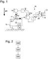
- the controller 2 determines the joint angles q 1 ,..., Q 7 on the basis of a model of the tool-free robot according to equation (1), model joint forces ⁇ model and from the deviation between the detected joint forces ⁇ mess and on Based on this model, the model joint forces ⁇ model according to equation (2) is an orientation of the robot relative to the actual current direction of gravity g , or a model joint forces ⁇ model determined from the deviation between the detected joint forces ⁇ mess and on the basis of the robot model dependent correction size.
- FIG. 1 illustrate: on the second joint (cf. q 2 ), essentially the weight of the robot members arranged distally of this joint acts (right in Fig. 1 ).
- the joint moment in the second joint thus depends on the weight of these links and the horizontal lever arm of the weight.
- the orientation of the robot 10 or its reference system (x, y, z) deviates from that in Fig. 1 (ideal) orientation from shown that develop the model and g is in its first or z-axis antiparallel current to the actual direction of gravity, so the actual effective horizontal lever arm and the joint torque in the second joint changes accordingly.
- the controller 2 can, conversely, use this deviation between the detected joint torque and the model joint torque determined on the basis of the model of the robot to orient the robot 10 or its robot (base) fixed reference system (x, y, z) relative to the actual current one gravity direction g is in the (xz) plane or a corresponding component of the correction quantity determined.
- the user can correct the orientation of the robot 10, in particular its platform 13, in such a way that the deviation between the orientation determined and the orientation on which the model is based or the correction quantity is minimized.
- the robot 10 can be aligned absolutely horizontally or vertically.
- the joint forces ⁇ mess acting in the joints are again recorded in steps S10-S30 at the further installation site (S10), the tool 12 now being fastened to the robot flange 16 from the joint angle q as in the calibration of the model of the tool-carrying robot 1 , ..., q 7 based on the model of the tool-guiding robot according to equation (1)
- model joint forces ⁇ model determined (S20) and a multidimensional correction variable with components in the x and y direction is displayed, for example linearly from the deviation between the detected joint forces ⁇ mess and the model joint forces ⁇ model (S30).
- the correction variable can be displayed, for example, in the form of the direction and / or angle of rotation about the x and y axis. Likewise, it can be displayed, for example, in the form of a direction arrow in the x-y plane into which the z-axis is to be tilted, the size of the direction arrow being able to indicate the tilt angle. For example, it can also be displayed in the form of a correction axis in the x-y plane, about which the z axis is to be tilted, in a further development the direction of rotation and / or tilt angle can be displayed, for example numerically.
- the user By changing the orientation of the platform 13 by retracting or extending the supports 15 in such a way that the displayed correction quantity is minimized, the user sets in the new or further set-up position again the same orientation that was present when the model of the tool-carrying robot was calibrated.
- a force sensor in the form of an in is on the base 11 or the flange 16 Fig. 1 Load cell 20 indicated by dashed lines.
- the controller 2 determines in step S20 the orientation of the load cell 20 or the robot on which it is arranged in a known orientation, in particular the orientation of its robot-based reference coordinate system, relative to the actual current direction of gravity, which is determined by the direction of the vector [m x , m y , m z ] T is determined. For example, if the load cell 20 detects only a negative weight (component) in its z-axis direction, this is in opposite directions parallel to the actual current direction of gravity.
Landscapes
- Engineering & Computer Science (AREA)
- Robotics (AREA)
- Mechanical Engineering (AREA)
- Human Computer Interaction (AREA)
- Manipulator (AREA)
Claims (15)
- Procédé de correction d'une orientation d'un robot (10) par rapport à la direction de la gravité (gint) au niveau d'au moins un emplacement du robot, avec les étapes de :détection (S10) de forces d'articulation du robot dans au moins une pose de mesure ; etdétermination (S20) d'une orientation du robot par rapport à la direction de la gravité sur la base des forces d'articulation détectées et d'un modèle du robot,caractérisé en ce queun écart entre l'orientation déterminée et une orientation sous-jacente au modèle est réduit par basculement du robot autour d'au moins un axe de correction (x, y).
- Procédé selon la revendication 1, caractérisé en ce que l'orientation est déterminée sur la base d'un écart entre les forces d'articulation détectées et les forces d'articulation du modèle déterminées sur la base du modèle du robot.
- Procédé selon l'une quelconque des revendications précédentes, caractérisé en ce que l'orientation est déterminée par rapport à une direction de la gravité actuelle réelle (gint) ou d'une direction de la gravité sous-jacente au modèle et émise, en particulier affichée (S30).
- Procédé selon l'une quelconque des revendications précédentes, caractérisé en ce qu'une grandeur de correction dépendant de l'écart entre les forces d'articulation détectées et les forces d'articulation du modèle déterminées sur la base du modèle du robot est déterminée et émise et/ou est réduite par basculement du robot autour d'au moins un axe de correction (x, y).
- Procédé selon l'une quelconque des revendications précédentes, caractérisé en ce que dans au moins une pose de mesure, au moins un axe de déplacement du robot forme un angle, qui est au maximum de 30°, avec un axe de correction (x) prédéfini fixe par rapport au robot, autour duquel une orientation du robot peut être corrigée.
- Procédé selon la revendication 5, caractérisé en ce que dans la pose de mesure, au moins un autre axe de déplacement du robot forme un angle, qui est au maximum de 30°, avec un autre axe de correction (y) prédéfini fixe par rapport au robot, autour duquel une orientation du robot peut être corrigée.
- Procédé selon l'une quelconque des revendications précédentes, caractérisé en ce que dans au moins une pose de mesure, une distance horizontale entre une bride distale (16) et une base (11) d'un bras du robot est d'au moins 50 % d'une distance horizontale maximum entre la bride et la base.
- Procédé selon l'une quelconque des revendications précédentes, caractérisé en ce que des forces d'articulation du robot sans outil sont détectées et le modèle est un modèle du robot sans outil.
- Procédé selon l'une quelconque des revendications précédentes, caractérisé en ce que des forces d'articulation du robot guidant l'outil, en particulier guidant la charge utile, sont détectées et le modèle est un modèle du robot guidant outil.
- Procédé selon la revendication 9, caractérisé en ce qu'au niveau d'au moins un emplacement, des paramètres du modèle du robot guidant l'outil sont calibrés dans au moins une pose de calibrage, et au niveau d'au moins un autre emplacement, l'orientation du robot est déterminée par rapport à la direction de la gravité sous-jacente au calibrage du modèle.
- Procédé selon la revendication 10, caractérisé en ce qu'au moins une pose de mesure pour la détermination de l'orientation du robot par rapport à la direction de la gravité au niveau de l'autre emplacement et au moins une pose de calibrage divergent l'une de l'autre de maximum 10 % d'une zone de déplacement maximum du robot.
- Procédé de détermination d'une orientation d'un robot (10) par rapport à une direction de la gravité (gint) au niveau d'au moins un emplacement du robot selon l'une quelconque des revendications précédentes, avec les étapes de :détection (S10) d'une force d'articulation dans au moins une pose de mesure du robot au moyen d'un capteur de force (20) agencé au niveau du robot, en particulier d'une base (11) ou d'une bride (16) du robot ; etdétermination (S20) d'une orientation du robot par rapport à la direction de la gravité sur la base de la force d'articulation détectée et d'une orientation connue du capteur de force par rapport au robot.
- Procédé selon l'une quelconque des revendications précédentes, caractérisé en ce que le robot est un robot mobile, en particulier une plateforme (13) mobile, en particulier déplaçable.
- Commande (2) pour la commande d'un robot (10), qui est aménagée pour la réalisation d'un procédé selon l'une quelconque des revendications précédentes et présente :des moyens (2) de détection de forces d'articulation du robot dans au moins une pose de mesure ; etdes moyens (2) de détermination d'une orientation du robot par rapport à la direction de la gravité sur la base des forces d'articulation détectées et d'un modèle du robot,
- Programme informatique, en particulier produit de programme informatique avec un code de programme, qui est enregistré sur un support lisible par un ordinateur, pour la réalisation d'un procédé selon l'une quelconque des revendications précédentes.
Applications Claiming Priority (2)
| Application Number | Priority Date | Filing Date | Title |
|---|---|---|---|
| DE102016000187.9A DE102016000187B3 (de) | 2016-01-11 | 2016-01-11 | Bestimmung einer Orientierung eines Roboters relativ zu einer Gravitationsrichtung |
| PCT/EP2017/000022 WO2017121635A1 (fr) | 2016-01-11 | 2017-01-09 | Détermination d'une orientation d'un robot par rapport à la direction de la gravité |
Publications (2)
| Publication Number | Publication Date |
|---|---|
| EP3402632A1 EP3402632A1 (fr) | 2018-11-21 |
| EP3402632B1 true EP3402632B1 (fr) | 2020-04-08 |
Family
ID=57738554
Family Applications (1)
| Application Number | Title | Priority Date | Filing Date |
|---|---|---|---|
| EP17700261.5A Active EP3402632B1 (fr) | 2016-01-11 | 2017-01-09 | Détermination d'une orientation d'un robot par rapport à la direction de la gravité |
Country Status (5)
| Country | Link |
|---|---|
| US (1) | US20190009410A1 (fr) |
| EP (1) | EP3402632B1 (fr) |
| CN (1) | CN108463314A (fr) |
| DE (1) | DE102016000187B3 (fr) |
| WO (1) | WO2017121635A1 (fr) |
Cited By (1)
| Publication number | Priority date | Publication date | Assignee | Title |
|---|---|---|---|---|
| EP3939753A1 (fr) * | 2020-07-17 | 2022-01-19 | Rethink Robotics GmbH | Procédé d'alignement d'un bras robotique |
Families Citing this family (16)
| Publication number | Priority date | Publication date | Assignee | Title |
|---|---|---|---|---|
| JP7427358B2 (ja) * | 2017-07-20 | 2024-02-05 | キヤノン株式会社 | ロボットシステム、物品の製造方法、制御方法、制御プログラム、および記録媒体 |
| JP6737831B2 (ja) * | 2018-04-17 | 2020-08-12 | ファナック株式会社 | 設置形態判定装置、設置形態判定用コンピュータプログラム及び記録媒体 |
| CN112368116A (zh) * | 2018-06-15 | 2021-02-12 | 优傲机器人公司 | 附接到机器人臂的有效载荷的估计 |
| DE102019101595B3 (de) * | 2019-01-23 | 2020-03-12 | Franka Emika Gmbh | Verfahren zum Ermitteln einer Gewichtskraft und eines Schwerpunktes einer Robotermanipulatorlast |
| DE102019107969B3 (de) * | 2019-03-28 | 2020-08-06 | Franka Emika Gmbh | Lagewinkelanzeige beim manuellen Führen eines Robotermanipulators |
| CN110238848B (zh) * | 2019-05-30 | 2022-07-05 | 埃夫特智能装备股份有限公司 | 一种机器人坐标系下重力矢量的计算方法 |
| DE102020101515A1 (de) | 2020-01-23 | 2021-07-29 | Deutsches Zentrum für Luft- und Raumfahrt e.V. | Verfahren, Computerprogrammprodukt und Roboter zum Bestimmen einer Orientierung eines Roboters in einem Gravitationsfeld |
| CN113492398B (zh) * | 2020-04-02 | 2022-12-20 | 北京配天技术有限公司 | 标定杆、重力加速度方向的标定系统及其标定方法 |
| CN112476435B (zh) * | 2020-11-25 | 2022-07-12 | 北京配天技术有限公司 | 重力加速度方向的标定方法、标定装置及存储介质 |
| US11931898B2 (en) | 2020-12-22 | 2024-03-19 | Boston Dynamics, Inc. | Arm and body coordination |
| CN112975960B (zh) * | 2021-02-10 | 2022-07-05 | 西北工业大学 | 一种机器人末端精细控制模型的建立与参数校准方法 |
| CN113386136B (zh) * | 2021-06-30 | 2022-05-20 | 华中科技大学 | 一种基于标准球阵目标估计的机器人位姿矫正方法及系统 |
| EP4119302A1 (fr) * | 2021-07-15 | 2023-01-18 | Siemens Aktiengesellschaft | Procédé pour estimer un ou plusieurs efforts de processus associés au point central d'outil d'une machine outil |
| CN113910255B (zh) * | 2021-10-13 | 2022-08-05 | 邦世科技(南京)有限公司 | 手术器械智能摆渡机器人及其控制方法 |
| CN116442246B (zh) * | 2023-06-14 | 2023-08-29 | 广州东焊智能装备有限公司 | 一种应用于机器人的姿态平衡控制方法 |
| CN116945195B (zh) * | 2023-09-19 | 2024-01-12 | 成都飞机工业(集团)有限责任公司 | 全向测量设备系统装置、配准方法、电子设备和存储介质 |
Family Cites Families (15)
| Publication number | Priority date | Publication date | Assignee | Title |
|---|---|---|---|---|
| US5239855A (en) * | 1991-07-12 | 1993-08-31 | Hewlett-Packard Company | Positional calibration of robotic arm joints relative to the gravity vector |
| DE10150225A1 (de) * | 2001-10-12 | 2003-04-17 | Tecmedic Gmbh | Verfahren zur Verringerung von Fehlern bei der Positionierung eines Roboters gegenüber einem Werkstück |
| US20100243344A1 (en) * | 2006-09-25 | 2010-09-30 | Board Of Trustees Of Leland Stanford Junior University | Electromechanically counterbalanced humanoid robotic system |
| WO2008105948A2 (fr) * | 2006-10-06 | 2008-09-04 | Irobot Corporation | Véhicule robotique |
| DE102007060682B4 (de) * | 2007-12-17 | 2015-08-20 | Kuka Roboter Gmbh | Verfahren und Vorrichtung zur modellbasierten Regelung eines Manipulators |
| DE102007062977B4 (de) * | 2007-12-21 | 2018-07-19 | Schott Ag | Verfahren zur Herstellung von Prozessgasen für die Dampfphasenabscheidung |
| DE102010052396A1 (de) * | 2010-11-24 | 2012-05-24 | Kuka Roboter Gmbh | Verfahren und Vorrichtung zum Steuern einer Peripheriekomponente eines Robotersystems |
| JP5895628B2 (ja) * | 2012-03-15 | 2016-03-30 | 株式会社ジェイテクト | ロボットの制御方法及びロボット制御装置、並びにロボット制御システム |
| JP5360254B2 (ja) * | 2012-03-21 | 2013-12-04 | トヨタ自動車株式会社 | トルク検出方法及びアーム装置 |
| CN102692873A (zh) * | 2012-05-07 | 2012-09-26 | 上海理工大学 | 工业机器人定位精度标定方法 |
| WO2014021433A1 (fr) * | 2012-08-02 | 2014-02-06 | 東芝機械株式会社 | Appareil robotisé et son procédé de commande |
| DE102013010290A1 (de) * | 2013-06-19 | 2014-12-24 | Kuka Laboratories Gmbh | Überwachen eines kinematisch redundanten Roboters |
| US9539059B2 (en) * | 2013-09-24 | 2017-01-10 | Sony Olympus Medical Solutions Inc. | Medical robot arm apparatus, medical robot arm control system, medical robot arm control method, and program |
| DE102014004238B4 (de) * | 2014-03-25 | 2018-12-13 | Deutsches Zentrum für Luft- und Raumfahrt e.V. | Robotersystem |
| JP6332197B2 (ja) * | 2015-08-11 | 2018-05-30 | トヨタ自動車株式会社 | モータの制御装置 |
-
2016
- 2016-01-11 DE DE102016000187.9A patent/DE102016000187B3/de not_active Expired - Fee Related
-
2017
- 2017-01-09 CN CN201780006370.8A patent/CN108463314A/zh active Pending
- 2017-01-09 EP EP17700261.5A patent/EP3402632B1/fr active Active
- 2017-01-09 US US16/068,239 patent/US20190009410A1/en not_active Abandoned
- 2017-01-09 WO PCT/EP2017/000022 patent/WO2017121635A1/fr active Application Filing
Non-Patent Citations (1)
| Title |
|---|
| None * |
Cited By (1)
| Publication number | Priority date | Publication date | Assignee | Title |
|---|---|---|---|---|
| EP3939753A1 (fr) * | 2020-07-17 | 2022-01-19 | Rethink Robotics GmbH | Procédé d'alignement d'un bras robotique |
Also Published As
| Publication number | Publication date |
|---|---|
| US20190009410A1 (en) | 2019-01-10 |
| WO2017121635A1 (fr) | 2017-07-20 |
| EP3402632A1 (fr) | 2018-11-21 |
| DE102016000187B3 (de) | 2017-01-26 |
| CN108463314A (zh) | 2018-08-28 |
Similar Documents
| Publication | Publication Date | Title |
|---|---|---|
| EP3402632B1 (fr) | Détermination d'une orientation d'un robot par rapport à la direction de la gravité | |
| DE112016002797B4 (de) | Kalibriervorrichtung und robotersystem mit einer solchen kalibriervorrichtung | |
| EP3323026B1 (fr) | Détermination d'une instruction d'entrée pour un robot, qui est entrée en exerçant manuellement une force sur le robot | |
| DE102016012065B4 (de) | Robotersystem mit Funktion zum Berechnen von Position und Ausrichtung eines Sensors | |
| EP2954986B1 (fr) | Dispositif et procédé de commande et de réglage d'un système multi-corps | |
| DE102015008144B4 (de) | Umschalten einer Steuerung eines Roboters in einen Handführ-Betriebsmodus | |
| DE102015002764B4 (de) | Robotersteuerung mit detektion eines kontaktes im externen umfeld | |
| EP2243602B1 (fr) | Procédé et dispositif de commande d'un manipulateur | |
| DE102006021084B4 (de) | Kalibrierungsverfahren für eine Parallelkinematikmechanismusmaschine | |
| DE102015004483B4 (de) | Robotersteuerung und Robotersystem zum Bewegen eines Roboters als Reaktion auf eine Kraft | |
| DE102015004481B4 (de) | Robotersteuervorrichtung zum Steuern eines gemäß einer ausgeübten Kraft bewegten Roboters | |
| DE102017130460B4 (de) | Verfahren und Vorrichtung zum Korrigieren von Roboterbewegungen | |
| DE102018210864B3 (de) | Verfahren und System zum Regeln eines Roboters | |
| WO2008104167A2 (fr) | Procédé de vérification et d'étalonnage de machine basé sur une singularité | |
| DE102018114644B3 (de) | Manueller Anlernvorgang an einem Robotermanipulator mit Kraft-/Momentenvorgabe | |
| EP3589458B1 (fr) | Dispositif d'analyse de déplacement et dispositif d'entrainement | |
| DE102018214257B3 (de) | Roboterregelung | |
| DE102017003993B4 (de) | Kalibrierung eines Roboters | |
| WO2019224288A1 (fr) | Détection de collisions fonction de la direction pour un manipulateur de robot | |
| DE102016013083B4 (de) | Kalibrieren eines Modells eines Prozess-Roboters und Betreiben eines Prozess-Roboters | |
| DE102019134666B4 (de) | Kalibrieren eines virtuellen Kraftsensors eines Robotermanipulators | |
| DE102022126205B4 (de) | Robotersystem zum Bewegen einer Nutzlast mit minimalem Schwanken der Nutzlast und erhöhter Positionierungsgenauigkeit | |
| DE102020209866B3 (de) | Verfahren und System zum Betreiben eines Roboters | |
| EP4084937B1 (fr) | Déplacement d'une référence fixée à un robot | |
| DE102022110140A1 (de) | Konforme präsentation der nutzlast durch ein robotersystem mit koordinierten seriellen und parallelen robotern |
Legal Events
| Date | Code | Title | Description |
|---|---|---|---|
| STAA | Information on the status of an ep patent application or granted ep patent |
Free format text: STATUS: UNKNOWN |
|
| STAA | Information on the status of an ep patent application or granted ep patent |
Free format text: STATUS: THE INTERNATIONAL PUBLICATION HAS BEEN MADE |
|
| PUAI | Public reference made under article 153(3) epc to a published international application that has entered the european phase |
Free format text: ORIGINAL CODE: 0009012 |
|
| STAA | Information on the status of an ep patent application or granted ep patent |
Free format text: STATUS: REQUEST FOR EXAMINATION WAS MADE |
|
| 17P | Request for examination filed |
Effective date: 20180629 |
|
| AK | Designated contracting states |
Kind code of ref document: A1 Designated state(s): AL AT BE BG CH CY CZ DE DK EE ES FI FR GB GR HR HU IE IS IT LI LT LU LV MC MK MT NL NO PL PT RO RS SE SI SK SM TR |
|
| AX | Request for extension of the european patent |
Extension state: BA ME |
|
| DAV | Request for validation of the european patent (deleted) | ||
| DAX | Request for extension of the european patent (deleted) | ||
| GRAP | Despatch of communication of intention to grant a patent |
Free format text: ORIGINAL CODE: EPIDOSNIGR1 |
|
| STAA | Information on the status of an ep patent application or granted ep patent |
Free format text: STATUS: GRANT OF PATENT IS INTENDED |
|
| INTG | Intention to grant announced |
Effective date: 20200117 |
|
| GRAS | Grant fee paid |
Free format text: ORIGINAL CODE: EPIDOSNIGR3 |
|
| GRAA | (expected) grant |
Free format text: ORIGINAL CODE: 0009210 |
|
| STAA | Information on the status of an ep patent application or granted ep patent |
Free format text: STATUS: THE PATENT HAS BEEN GRANTED |
|
| AK | Designated contracting states |
Kind code of ref document: B1 Designated state(s): AL AT BE BG CH CY CZ DE DK EE ES FI FR GB GR HR HU IE IS IT LI LT LU LV MC MK MT NL NO PL PT RO RS SE SI SK SM TR |
|
| REG | Reference to a national code |
Ref country code: AT Ref legal event code: REF Ref document number: 1253744 Country of ref document: AT Kind code of ref document: T Effective date: 20200415 Ref country code: CH Ref legal event code: EP |
|
| REG | Reference to a national code |
Ref country code: DE Ref legal event code: R096 Ref document number: 502017004625 Country of ref document: DE |
|
| REG | Reference to a national code |
Ref country code: IE Ref legal event code: FG4D Free format text: LANGUAGE OF EP DOCUMENT: GERMAN |
|
| REG | Reference to a national code |
Ref country code: NL Ref legal event code: MP Effective date: 20200408 |
|
| REG | Reference to a national code |
Ref country code: LT Ref legal event code: MG4D |
|
| PG25 | Lapsed in a contracting state [announced via postgrant information from national office to epo] |
Ref country code: GR Free format text: LAPSE BECAUSE OF FAILURE TO SUBMIT A TRANSLATION OF THE DESCRIPTION OR TO PAY THE FEE WITHIN THE PRESCRIBED TIME-LIMIT Effective date: 20200709 Ref country code: PT Free format text: LAPSE BECAUSE OF FAILURE TO SUBMIT A TRANSLATION OF THE DESCRIPTION OR TO PAY THE FEE WITHIN THE PRESCRIBED TIME-LIMIT Effective date: 20200817 Ref country code: IS Free format text: LAPSE BECAUSE OF FAILURE TO SUBMIT A TRANSLATION OF THE DESCRIPTION OR TO PAY THE FEE WITHIN THE PRESCRIBED TIME-LIMIT Effective date: 20200808 Ref country code: FI Free format text: LAPSE BECAUSE OF FAILURE TO SUBMIT A TRANSLATION OF THE DESCRIPTION OR TO PAY THE FEE WITHIN THE PRESCRIBED TIME-LIMIT Effective date: 20200408 Ref country code: SE Free format text: LAPSE BECAUSE OF FAILURE TO SUBMIT A TRANSLATION OF THE DESCRIPTION OR TO PAY THE FEE WITHIN THE PRESCRIBED TIME-LIMIT Effective date: 20200408 Ref country code: NO Free format text: LAPSE BECAUSE OF FAILURE TO SUBMIT A TRANSLATION OF THE DESCRIPTION OR TO PAY THE FEE WITHIN THE PRESCRIBED TIME-LIMIT Effective date: 20200708 Ref country code: NL Free format text: LAPSE BECAUSE OF FAILURE TO SUBMIT A TRANSLATION OF THE DESCRIPTION OR TO PAY THE FEE WITHIN THE PRESCRIBED TIME-LIMIT Effective date: 20200408 Ref country code: LT Free format text: LAPSE BECAUSE OF FAILURE TO SUBMIT A TRANSLATION OF THE DESCRIPTION OR TO PAY THE FEE WITHIN THE PRESCRIBED TIME-LIMIT Effective date: 20200408 |
|
| PG25 | Lapsed in a contracting state [announced via postgrant information from national office to epo] |
Ref country code: BG Free format text: LAPSE BECAUSE OF FAILURE TO SUBMIT A TRANSLATION OF THE DESCRIPTION OR TO PAY THE FEE WITHIN THE PRESCRIBED TIME-LIMIT Effective date: 20200708 Ref country code: LV Free format text: LAPSE BECAUSE OF FAILURE TO SUBMIT A TRANSLATION OF THE DESCRIPTION OR TO PAY THE FEE WITHIN THE PRESCRIBED TIME-LIMIT Effective date: 20200408 Ref country code: HR Free format text: LAPSE BECAUSE OF FAILURE TO SUBMIT A TRANSLATION OF THE DESCRIPTION OR TO PAY THE FEE WITHIN THE PRESCRIBED TIME-LIMIT Effective date: 20200408 Ref country code: RS Free format text: LAPSE BECAUSE OF FAILURE TO SUBMIT A TRANSLATION OF THE DESCRIPTION OR TO PAY THE FEE WITHIN THE PRESCRIBED TIME-LIMIT Effective date: 20200408 |
|
| PG25 | Lapsed in a contracting state [announced via postgrant information from national office to epo] |
Ref country code: AL Free format text: LAPSE BECAUSE OF FAILURE TO SUBMIT A TRANSLATION OF THE DESCRIPTION OR TO PAY THE FEE WITHIN THE PRESCRIBED TIME-LIMIT Effective date: 20200408 |
|
| REG | Reference to a national code |
Ref country code: DE Ref legal event code: R097 Ref document number: 502017004625 Country of ref document: DE |
|
| PG25 | Lapsed in a contracting state [announced via postgrant information from national office to epo] |
Ref country code: ES Free format text: LAPSE BECAUSE OF FAILURE TO SUBMIT A TRANSLATION OF THE DESCRIPTION OR TO PAY THE FEE WITHIN THE PRESCRIBED TIME-LIMIT Effective date: 20200408 Ref country code: DK Free format text: LAPSE BECAUSE OF FAILURE TO SUBMIT A TRANSLATION OF THE DESCRIPTION OR TO PAY THE FEE WITHIN THE PRESCRIBED TIME-LIMIT Effective date: 20200408 Ref country code: EE Free format text: LAPSE BECAUSE OF FAILURE TO SUBMIT A TRANSLATION OF THE DESCRIPTION OR TO PAY THE FEE WITHIN THE PRESCRIBED TIME-LIMIT Effective date: 20200408 Ref country code: IT Free format text: LAPSE BECAUSE OF FAILURE TO SUBMIT A TRANSLATION OF THE DESCRIPTION OR TO PAY THE FEE WITHIN THE PRESCRIBED TIME-LIMIT Effective date: 20200408 Ref country code: SM Free format text: LAPSE BECAUSE OF FAILURE TO SUBMIT A TRANSLATION OF THE DESCRIPTION OR TO PAY THE FEE WITHIN THE PRESCRIBED TIME-LIMIT Effective date: 20200408 Ref country code: CZ Free format text: LAPSE BECAUSE OF FAILURE TO SUBMIT A TRANSLATION OF THE DESCRIPTION OR TO PAY THE FEE WITHIN THE PRESCRIBED TIME-LIMIT Effective date: 20200408 Ref country code: RO Free format text: LAPSE BECAUSE OF FAILURE TO SUBMIT A TRANSLATION OF THE DESCRIPTION OR TO PAY THE FEE WITHIN THE PRESCRIBED TIME-LIMIT Effective date: 20200408 |
|
| PLBE | No opposition filed within time limit |
Free format text: ORIGINAL CODE: 0009261 |
|
| STAA | Information on the status of an ep patent application or granted ep patent |
Free format text: STATUS: NO OPPOSITION FILED WITHIN TIME LIMIT |
|
| PG25 | Lapsed in a contracting state [announced via postgrant information from national office to epo] |
Ref country code: PL Free format text: LAPSE BECAUSE OF FAILURE TO SUBMIT A TRANSLATION OF THE DESCRIPTION OR TO PAY THE FEE WITHIN THE PRESCRIBED TIME-LIMIT Effective date: 20200408 Ref country code: SK Free format text: LAPSE BECAUSE OF FAILURE TO SUBMIT A TRANSLATION OF THE DESCRIPTION OR TO PAY THE FEE WITHIN THE PRESCRIBED TIME-LIMIT Effective date: 20200408 |
|
| 26N | No opposition filed |
Effective date: 20210112 |
|
| PG25 | Lapsed in a contracting state [announced via postgrant information from national office to epo] |
Ref country code: SI Free format text: LAPSE BECAUSE OF FAILURE TO SUBMIT A TRANSLATION OF THE DESCRIPTION OR TO PAY THE FEE WITHIN THE PRESCRIBED TIME-LIMIT Effective date: 20200408 |
|
| REG | Reference to a national code |
Ref country code: DE Ref legal event code: R119 Ref document number: 502017004625 Country of ref document: DE |
|
| PG25 | Lapsed in a contracting state [announced via postgrant information from national office to epo] |
Ref country code: MC Free format text: LAPSE BECAUSE OF FAILURE TO SUBMIT A TRANSLATION OF THE DESCRIPTION OR TO PAY THE FEE WITHIN THE PRESCRIBED TIME-LIMIT Effective date: 20200408 |
|
| REG | Reference to a national code |
Ref country code: CH Ref legal event code: PL |
|
| GBPC | Gb: european patent ceased through non-payment of renewal fee |
Effective date: 20210109 |
|
| PG25 | Lapsed in a contracting state [announced via postgrant information from national office to epo] |
Ref country code: LU Free format text: LAPSE BECAUSE OF NON-PAYMENT OF DUE FEES Effective date: 20210109 |
|
| REG | Reference to a national code |
Ref country code: BE Ref legal event code: MM Effective date: 20210131 |
|
| PG25 | Lapsed in a contracting state [announced via postgrant information from national office to epo] |
Ref country code: FR Free format text: LAPSE BECAUSE OF NON-PAYMENT OF DUE FEES Effective date: 20210131 |
|
| PG25 | Lapsed in a contracting state [announced via postgrant information from national office to epo] |
Ref country code: DE Free format text: LAPSE BECAUSE OF NON-PAYMENT OF DUE FEES Effective date: 20210803 Ref country code: CH Free format text: LAPSE BECAUSE OF NON-PAYMENT OF DUE FEES Effective date: 20210131 Ref country code: GB Free format text: LAPSE BECAUSE OF NON-PAYMENT OF DUE FEES Effective date: 20210109 Ref country code: LI Free format text: LAPSE BECAUSE OF NON-PAYMENT OF DUE FEES Effective date: 20210131 |
|
| PG25 | Lapsed in a contracting state [announced via postgrant information from national office to epo] |
Ref country code: IE Free format text: LAPSE BECAUSE OF NON-PAYMENT OF DUE FEES Effective date: 20210109 |
|
| PG25 | Lapsed in a contracting state [announced via postgrant information from national office to epo] |
Ref country code: BE Free format text: LAPSE BECAUSE OF NON-PAYMENT OF DUE FEES Effective date: 20210131 |
|
| REG | Reference to a national code |
Ref country code: AT Ref legal event code: MM01 Ref document number: 1253744 Country of ref document: AT Kind code of ref document: T Effective date: 20220109 |
|
| PG25 | Lapsed in a contracting state [announced via postgrant information from national office to epo] |
Ref country code: AT Free format text: LAPSE BECAUSE OF NON-PAYMENT OF DUE FEES Effective date: 20220109 |
|
| PG25 | Lapsed in a contracting state [announced via postgrant information from national office to epo] |
Ref country code: CY Free format text: LAPSE BECAUSE OF FAILURE TO SUBMIT A TRANSLATION OF THE DESCRIPTION OR TO PAY THE FEE WITHIN THE PRESCRIBED TIME-LIMIT Effective date: 20200408 |
|
| P01 | Opt-out of the competence of the unified patent court (upc) registered |
Effective date: 20230528 |
|
| PG25 | Lapsed in a contracting state [announced via postgrant information from national office to epo] |
Ref country code: HU Free format text: LAPSE BECAUSE OF FAILURE TO SUBMIT A TRANSLATION OF THE DESCRIPTION OR TO PAY THE FEE WITHIN THE PRESCRIBED TIME-LIMIT; INVALID AB INITIO Effective date: 20170109 |
|
| PG25 | Lapsed in a contracting state [announced via postgrant information from national office to epo] |
Ref country code: MK Free format text: LAPSE BECAUSE OF FAILURE TO SUBMIT A TRANSLATION OF THE DESCRIPTION OR TO PAY THE FEE WITHIN THE PRESCRIBED TIME-LIMIT Effective date: 20200408 |