EP3402619B1 - Methods for producing forged products and other worked products - Google Patents
Methods for producing forged products and other worked products Download PDFInfo
- Publication number
- EP3402619B1 EP3402619B1 EP17705984.7A EP17705984A EP3402619B1 EP 3402619 B1 EP3402619 B1 EP 3402619B1 EP 17705984 A EP17705984 A EP 17705984A EP 3402619 B1 EP3402619 B1 EP 3402619B1
- Authority
- EP
- European Patent Office
- Prior art keywords
- preform
- metal shaped
- smoothing
- forging
- metal
- Prior art date
- Legal status (The legal status is an assumption and is not a legal conclusion. Google has not performed a legal analysis and makes no representation as to the accuracy of the status listed.)
- Active
Links
- 238000000034 method Methods 0.000 title claims description 63
- 229910052751 metal Inorganic materials 0.000 claims description 226
- 239000002184 metal Substances 0.000 claims description 226
- 238000005242 forging Methods 0.000 claims description 141
- 238000004519 manufacturing process Methods 0.000 claims description 90
- 239000000654 additive Substances 0.000 claims description 81
- 230000000996 additive effect Effects 0.000 claims description 81
- 238000009499 grossing Methods 0.000 claims description 79
- 239000000758 substrate Substances 0.000 claims description 54
- 238000010438 heat treatment Methods 0.000 claims description 30
- 230000003746 surface roughness Effects 0.000 claims description 24
- 230000007547 defect Effects 0.000 claims description 21
- 238000005096 rolling process Methods 0.000 claims description 20
- 239000011324 bead Substances 0.000 claims description 15
- 238000010894 electron beam technology Methods 0.000 claims description 14
- 230000008018 melting Effects 0.000 claims description 14
- 238000002844 melting Methods 0.000 claims description 14
- 239000000843 powder Substances 0.000 claims description 5
- 238000000608 laser ablation Methods 0.000 claims description 2
- 239000000047 product Substances 0.000 description 111
- 239000000463 material Substances 0.000 description 65
- 229910000883 Ti6Al4V Inorganic materials 0.000 description 39
- 229910001069 Ti alloy Inorganic materials 0.000 description 23
- 229910045601 alloy Inorganic materials 0.000 description 19
- 239000000956 alloy Substances 0.000 description 19
- 238000000151 deposition Methods 0.000 description 19
- 238000000137 annealing Methods 0.000 description 18
- 230000008021 deposition Effects 0.000 description 16
- 229910052782 aluminium Inorganic materials 0.000 description 13
- XAGFODPZIPBFFR-UHFFFAOYSA-N aluminium Chemical compound [Al] XAGFODPZIPBFFR-UHFFFAOYSA-N 0.000 description 13
- 239000010936 titanium Substances 0.000 description 13
- 230000008569 process Effects 0.000 description 12
- 229910052719 titanium Inorganic materials 0.000 description 12
- 238000012545 processing Methods 0.000 description 11
- 229910021324 titanium aluminide Inorganic materials 0.000 description 11
- OQPDWFJSZHWILH-UHFFFAOYSA-N [Al].[Al].[Al].[Ti] Chemical compound [Al].[Al].[Al].[Ti] OQPDWFJSZHWILH-UHFFFAOYSA-N 0.000 description 10
- 238000001125 extrusion Methods 0.000 description 10
- 238000001000 micrograph Methods 0.000 description 10
- PXHVJJICTQNCMI-UHFFFAOYSA-N Nickel Chemical compound [Ni] PXHVJJICTQNCMI-UHFFFAOYSA-N 0.000 description 8
- RTAQQCXQSZGOHL-UHFFFAOYSA-N Titanium Chemical compound [Ti] RTAQQCXQSZGOHL-UHFFFAOYSA-N 0.000 description 6
- 238000005275 alloying Methods 0.000 description 6
- 238000007689 inspection Methods 0.000 description 6
- 230000007246 mechanism Effects 0.000 description 6
- 229910000831 Steel Inorganic materials 0.000 description 5
- 229910010038 TiAl Inorganic materials 0.000 description 5
- 238000003754 machining Methods 0.000 description 5
- 239000010935 stainless steel Substances 0.000 description 5
- 229910001220 stainless steel Inorganic materials 0.000 description 5
- 239000010959 steel Substances 0.000 description 5
- XEEYBQQBJWHFJM-UHFFFAOYSA-N Iron Chemical compound [Fe] XEEYBQQBJWHFJM-UHFFFAOYSA-N 0.000 description 4
- 238000004458 analytical method Methods 0.000 description 4
- 238000005516 engineering process Methods 0.000 description 4
- 238000000227 grinding Methods 0.000 description 4
- 238000010275 isothermal forging Methods 0.000 description 4
- 229910052759 nickel Inorganic materials 0.000 description 4
- 238000012876 topography Methods 0.000 description 4
- 229910021330 Ti3Al Inorganic materials 0.000 description 3
- 230000015572 biosynthetic process Effects 0.000 description 3
- 230000001419 dependent effect Effects 0.000 description 3
- 238000013461 design Methods 0.000 description 3
- 239000012467 final product Substances 0.000 description 3
- XLYOFNOQVPJJNP-UHFFFAOYSA-N water Substances O XLYOFNOQVPJJNP-UHFFFAOYSA-N 0.000 description 3
- 229910001152 Bi alloy Inorganic materials 0.000 description 2
- OKTJSMMVPCPJKN-UHFFFAOYSA-N Carbon Chemical compound [C] OKTJSMMVPCPJKN-UHFFFAOYSA-N 0.000 description 2
- -1 INCONEL) Chemical compound 0.000 description 2
- 229910000990 Ni alloy Inorganic materials 0.000 description 2
- 230000006978 adaptation Effects 0.000 description 2
- 238000013459 approach Methods 0.000 description 2
- 229910052799 carbon Inorganic materials 0.000 description 2
- 238000009826 distribution Methods 0.000 description 2
- 229910001026 inconel Inorganic materials 0.000 description 2
- 229910052742 iron Inorganic materials 0.000 description 2
- 239000011159 matrix material Substances 0.000 description 2
- 239000011156 metal matrix composite Substances 0.000 description 2
- 150000002739 metals Chemical class 0.000 description 2
- 238000012986 modification Methods 0.000 description 2
- 230000004048 modification Effects 0.000 description 2
- 230000037361 pathway Effects 0.000 description 2
- 238000002360 preparation method Methods 0.000 description 2
- 238000003825 pressing Methods 0.000 description 2
- 230000009467 reduction Effects 0.000 description 2
- 230000035882 stress Effects 0.000 description 2
- 229910052720 vanadium Inorganic materials 0.000 description 2
- LEONUFNNVUYDNQ-UHFFFAOYSA-N vanadium atom Chemical compound [V] LEONUFNNVUYDNQ-UHFFFAOYSA-N 0.000 description 2
- 229910000838 Al alloy Inorganic materials 0.000 description 1
- 241001522301 Apogonichthyoides nigripinnis Species 0.000 description 1
- VYZAMTAEIAYCRO-UHFFFAOYSA-N Chromium Chemical compound [Cr] VYZAMTAEIAYCRO-UHFFFAOYSA-N 0.000 description 1
- 230000009471 action Effects 0.000 description 1
- 230000032683 aging Effects 0.000 description 1
- 238000000149 argon plasma sintering Methods 0.000 description 1
- 239000011230 binding agent Substances 0.000 description 1
- 229910052804 chromium Inorganic materials 0.000 description 1
- 239000011651 chromium Substances 0.000 description 1
- 238000005520 cutting process Methods 0.000 description 1
- 230000003247 decreasing effect Effects 0.000 description 1
- 230000001066 destructive effect Effects 0.000 description 1
- 238000011143 downstream manufacturing Methods 0.000 description 1
- 230000000694 effects Effects 0.000 description 1
- 238000009760 electrical discharge machining Methods 0.000 description 1
- 238000011156 evaluation Methods 0.000 description 1
- 230000001747 exhibiting effect Effects 0.000 description 1
- 230000004927 fusion Effects 0.000 description 1
- 239000013067 intermediate product Substances 0.000 description 1
- 238000003475 lamination Methods 0.000 description 1
- 238000005259 measurement Methods 0.000 description 1
- 239000000155 melt Substances 0.000 description 1
- 238000001465 metallisation Methods 0.000 description 1
- 239000000203 mixture Substances 0.000 description 1
- 230000006911 nucleation Effects 0.000 description 1
- 238000010899 nucleation Methods 0.000 description 1
- 230000000737 periodic effect Effects 0.000 description 1
- 239000002243 precursor Substances 0.000 description 1
- 238000007639 printing Methods 0.000 description 1
- 238000001314 profilometry Methods 0.000 description 1
- 238000007493 shaping process Methods 0.000 description 1
- 239000011343 solid material Substances 0.000 description 1
- 230000003068 static effect Effects 0.000 description 1
- 238000012360 testing method Methods 0.000 description 1
- 238000003466 welding Methods 0.000 description 1
- 238000009763 wire-cut EDM Methods 0.000 description 1
Images


Classifications
-
- B—PERFORMING OPERATIONS; TRANSPORTING
- B21—MECHANICAL METAL-WORKING WITHOUT ESSENTIALLY REMOVING MATERIAL; PUNCHING METAL
- B21J—FORGING; HAMMERING; PRESSING METAL; RIVETING; FORGE FURNACES
- B21J5/00—Methods for forging, hammering, or pressing; Special equipment or accessories therefor
- B21J5/002—Hybrid process, e.g. forging following casting
-
- B—PERFORMING OPERATIONS; TRANSPORTING
- B21—MECHANICAL METAL-WORKING WITHOUT ESSENTIALLY REMOVING MATERIAL; PUNCHING METAL
- B21J—FORGING; HAMMERING; PRESSING METAL; RIVETING; FORGE FURNACES
- B21J5/00—Methods for forging, hammering, or pressing; Special equipment or accessories therefor
-
- B—PERFORMING OPERATIONS; TRANSPORTING
- B23—MACHINE TOOLS; METAL-WORKING NOT OTHERWISE PROVIDED FOR
- B23K—SOLDERING OR UNSOLDERING; WELDING; CLADDING OR PLATING BY SOLDERING OR WELDING; CUTTING BY APPLYING HEAT LOCALLY, e.g. FLAME CUTTING; WORKING BY LASER BEAM
- B23K26/00—Working by laser beam, e.g. welding, cutting or boring
- B23K26/0093—Working by laser beam, e.g. welding, cutting or boring combined with mechanical machining or metal-working covered by other subclasses than B23K
-
- B—PERFORMING OPERATIONS; TRANSPORTING
- B23—MACHINE TOOLS; METAL-WORKING NOT OTHERWISE PROVIDED FOR
- B23K—SOLDERING OR UNSOLDERING; WELDING; CLADDING OR PLATING BY SOLDERING OR WELDING; CUTTING BY APPLYING HEAT LOCALLY, e.g. FLAME CUTTING; WORKING BY LASER BEAM
- B23K15/00—Electron-beam welding or cutting
- B23K15/0046—Welding
- B23K15/0086—Welding welding for purposes other than joining, e.g. built-up welding
-
- B—PERFORMING OPERATIONS; TRANSPORTING
- B23—MACHINE TOOLS; METAL-WORKING NOT OTHERWISE PROVIDED FOR
- B23K—SOLDERING OR UNSOLDERING; WELDING; CLADDING OR PLATING BY SOLDERING OR WELDING; CUTTING BY APPLYING HEAT LOCALLY, e.g. FLAME CUTTING; WORKING BY LASER BEAM
- B23K15/00—Electron-beam welding or cutting
- B23K15/0046—Welding
- B23K15/0093—Welding characterised by the properties of the materials to be welded
-
- B—PERFORMING OPERATIONS; TRANSPORTING
- B23—MACHINE TOOLS; METAL-WORKING NOT OTHERWISE PROVIDED FOR
- B23K—SOLDERING OR UNSOLDERING; WELDING; CLADDING OR PLATING BY SOLDERING OR WELDING; CUTTING BY APPLYING HEAT LOCALLY, e.g. FLAME CUTTING; WORKING BY LASER BEAM
- B23K15/00—Electron-beam welding or cutting
- B23K15/08—Removing material, e.g. by cutting, by hole drilling
-
- B—PERFORMING OPERATIONS; TRANSPORTING
- B23—MACHINE TOOLS; METAL-WORKING NOT OTHERWISE PROVIDED FOR
- B23K—SOLDERING OR UNSOLDERING; WELDING; CLADDING OR PLATING BY SOLDERING OR WELDING; CUTTING BY APPLYING HEAT LOCALLY, e.g. FLAME CUTTING; WORKING BY LASER BEAM
- B23K26/00—Working by laser beam, e.g. welding, cutting or boring
- B23K26/34—Laser welding for purposes other than joining
- B23K26/342—Build-up welding
-
- B—PERFORMING OPERATIONS; TRANSPORTING
- B23—MACHINE TOOLS; METAL-WORKING NOT OTHERWISE PROVIDED FOR
- B23K—SOLDERING OR UNSOLDERING; WELDING; CLADDING OR PLATING BY SOLDERING OR WELDING; CUTTING BY APPLYING HEAT LOCALLY, e.g. FLAME CUTTING; WORKING BY LASER BEAM
- B23K26/00—Working by laser beam, e.g. welding, cutting or boring
- B23K26/352—Working by laser beam, e.g. welding, cutting or boring for surface treatment
- B23K26/354—Working by laser beam, e.g. welding, cutting or boring for surface treatment by melting
-
- B—PERFORMING OPERATIONS; TRANSPORTING
- B23—MACHINE TOOLS; METAL-WORKING NOT OTHERWISE PROVIDED FOR
- B23K—SOLDERING OR UNSOLDERING; WELDING; CLADDING OR PLATING BY SOLDERING OR WELDING; CUTTING BY APPLYING HEAT LOCALLY, e.g. FLAME CUTTING; WORKING BY LASER BEAM
- B23K26/00—Working by laser beam, e.g. welding, cutting or boring
- B23K26/352—Working by laser beam, e.g. welding, cutting or boring for surface treatment
- B23K26/3568—Modifying rugosity
- B23K26/3576—Diminishing rugosity, e.g. grinding; Polishing; Smoothing
-
- B—PERFORMING OPERATIONS; TRANSPORTING
- B23—MACHINE TOOLS; METAL-WORKING NOT OTHERWISE PROVIDED FOR
- B23K—SOLDERING OR UNSOLDERING; WELDING; CLADDING OR PLATING BY SOLDERING OR WELDING; CUTTING BY APPLYING HEAT LOCALLY, e.g. FLAME CUTTING; WORKING BY LASER BEAM
- B23K26/00—Working by laser beam, e.g. welding, cutting or boring
- B23K26/36—Removing material
- B23K26/361—Removing material for deburring or mechanical trimming
-
- B—PERFORMING OPERATIONS; TRANSPORTING
- B33—ADDITIVE MANUFACTURING TECHNOLOGY
- B33Y—ADDITIVE MANUFACTURING, i.e. MANUFACTURING OF THREE-DIMENSIONAL [3-D] OBJECTS BY ADDITIVE DEPOSITION, ADDITIVE AGGLOMERATION OR ADDITIVE LAYERING, e.g. BY 3-D PRINTING, STEREOLITHOGRAPHY OR SELECTIVE LASER SINTERING
- B33Y10/00—Processes of additive manufacturing
-
- B—PERFORMING OPERATIONS; TRANSPORTING
- B23—MACHINE TOOLS; METAL-WORKING NOT OTHERWISE PROVIDED FOR
- B23K—SOLDERING OR UNSOLDERING; WELDING; CLADDING OR PLATING BY SOLDERING OR WELDING; CUTTING BY APPLYING HEAT LOCALLY, e.g. FLAME CUTTING; WORKING BY LASER BEAM
- B23K2103/00—Materials to be soldered, welded or cut
- B23K2103/08—Non-ferrous metals or alloys
- B23K2103/14—Titanium or alloys thereof
-
- Y—GENERAL TAGGING OF NEW TECHNOLOGICAL DEVELOPMENTS; GENERAL TAGGING OF CROSS-SECTIONAL TECHNOLOGIES SPANNING OVER SEVERAL SECTIONS OF THE IPC; TECHNICAL SUBJECTS COVERED BY FORMER USPC CROSS-REFERENCE ART COLLECTIONS [XRACs] AND DIGESTS
- Y02—TECHNOLOGIES OR APPLICATIONS FOR MITIGATION OR ADAPTATION AGAINST CLIMATE CHANGE
- Y02P—CLIMATE CHANGE MITIGATION TECHNOLOGIES IN THE PRODUCTION OR PROCESSING OF GOODS
- Y02P10/00—Technologies related to metal processing
- Y02P10/25—Process efficiency
Definitions
- the present disclosure is directed towards methods of additively manufacturing metal components. More specifically, the present disclosure is directed towards different embodiments of additively manufacturing and smoothing an AM preform to configure an AM preform for downstream processing (working, forging, and the like).
- Metal products may be formed into shapes via forging operations.
- several successive dies flat dies and/or differently shaped dies
- the flat die or the die cavity in a first of the dies being designed to deform the forging stock to a first shape defined by the configuration of that particular die, and with the next die being shaped to perform a next successive step in the forging deformation of the stock, and so on, until the final die ultimately gives the forged part a fully deformed shape.
- U.S. Patent No. 4,055,975 See, U.S. Patent No. 4,055,975 .
- US 2015/013144 A1 which is considered as the closest prior art to claim 1, discloses a method, comprising using additive manufacturing to produce a metal shaped-preform, wherein the metal shaped-preform comprises a plurality of undulations on a surface of the metal shaped preform indicative of an additive manufacturing build and working the metal shaped-preform to a final worked product.
- a method includes using additive manufacturing to produce a metal shaped-preform. After the using step (e.g. producing a metal shaped-preform using/via additive manufacturing), the metal shaped-preform may be forged into a final forged product.
- the forging step comprises a single die forging step.
- a single forging step is represented by a single heat and forge cycle.
- the forge cycle includes multiple deformations without a heating cycle between the deformations.
- a heat cycle represents heating the material to the specified temperature prior to the forging deformation step.
- the metal preform comprises at least one of titanium, aluminum, nickel, steel, stainless steel, and titanium aluminide.
- the metal shaped-preform may be a titanium alloy.
- the metal shaped-preform may comprise a Ti-6Al-4V alloy.
- the metal shaped-preform may be an aluminum alloy.
- the metal shaped-preform may be a nickel alloy.
- the metal shaped-preform may be one of a steel and a stainless steel.
- the metal shaped-preform may be a metal matrix composite.
- the metal shaped-preform may comprise titanium aluminide.
- the titanium alloy may include at least 48 wt. % Ti and at least one titanium aluminide phase, wherein the at least one titanium aluminide phase is selected from the group consisting of TbAl, TiAl and combinations thereof.
- the titanium alloy includes at least 49 wt. % Ti.
- the titanium alloy includes at least 50 wt. % Ti.
- the titanium alloy includes 5-49 wt. % aluminum.
- the titanium alloy includes 30-49 wt. % aluminum, and the titanium alloy comprises at least some TiAl.
- the titanium alloy includes 5-30 wt. % aluminum, and the titanium alloy comprises at least some ThAl.
- the forging step may comprise heating the metal shaped-preform to a stock temperature, and bringing the metal shaped-preform to the forging die which has been heated separately to the desired temperature, and contacting the metal shaped-preform with a forging die.
- the die may be at a temperature that is nominally equal to the metal shaped-preform temperature (e.g. isothermal forging).
- the forging die when the contacting step is initiated, may be a temperature that is at least 6°C (10°F) lower than the stock temperature.
- the forging die is a temperature that is at least 14°C (25°F) lower than the stock temperature.
- the forging die when the contacting step is initiated, is a temperature that is at least 28°C (50°F) lower than the stock temperature. In another embodiment, when the contacting step is initiated, the forging die is a temperature that is at least 56°C (100°F) lower than the stock temperature. In yet another embodiment, when the contacting step is initiated, the forging die is a temperature that is at least 111°C (200°F) lower than the stock temperature.
- the final forged product is a component for an engine.
- the final forged product is a blade for a jet engine.
- the final forged product is a component for a vehicle (e.g. land, water, air, and combinations thereof).
- the final forged product is a structural component of a vehicle.
- the final forged product is a structural aerospace component (e.g. spar, rib, attachment fitting, window frame, landing gear, etc.).
- the final forged product is a structural component for a land-based turbine application.
- the final forged product is a component for a land-based and/or water-based vehicle.
- the final forged product is an engine containment ring.
- a method comprises using additive manufacturing to produce a metal shaped-preform, and concomitant to, or after the using step, working the metal shaped-preform into a final worked product via at least one of: (i) rolling, (ii) ring rolling, (iii) ring forging, (iv) shape rolling, (v) extruding, and (vi) combinations thereof.
- the working is rolling.
- the working is ring rolling.
- the working is ring forging.
- the working is shaped rolling.
- the working is extruding.
- one such reason for producing an additively manufactured billet for these processes is to enable (e.g. configure) bi-alloy or multi-alloy starting stock for rolling, forging, or extrusion operations.
- the bi-alloy or multi-alloy starting stock is unachievable using conventional billet and starting stock methods.
- the forging step comprises heating the metal shaped-preform to a stock temperature, and contacting the metal shaped-preform with a forging die.
- the contacting step comprises deforming the metal shaped-preform via the forging die.
- the contacting step comprises deforming the metal shaped-preform via the forging die to realize a true strain of from 0.05 to 1.10 in the metal shaped-preform.
- the contacting step comprises deforming the metal shaped-preform via the forging die to realize a true strain of at least 0.10 in the metal shaped-preform.
- the contacting step comprises deforming the metal shaped-preform via the forging die to realize a true strain of at least 0.20 in the metal shaped-preform. In another embodiment, the contacting step comprises deforming the metal shaped-preform via the forging die to realize a true strain of at least 0.25 in the metal shaped-preform. In yet another embodiment, the contacting step comprises deforming the metal shaped-preform via the forging die to realize a true strain of at least 0.30 in the metal shaped-preform. In another embodiment, the contacting step comprises deforming the metal shaped-preform via the forging die to realize a true strain of at least 0.35 in the metal shaped-preform.
- the contacting step comprises deforming the metal shaped-preform via the forging die to realize a true strain of not greater than 1.00 in the metal shaped-preform. In yet another embodiment, the contacting step comprises deforming the metal shaped-preform via the forging die to realize a true strain of not greater than 0.90 in the metal shaped-preform. In another embodiment, the contacting step comprises deforming the metal shaped-preform via the forging die to realize a true strain of not greater than 0.80 in the metal shaped-preform. In yet another embodiment, the contacting step comprises deforming the metal shaped-preform via the forging die to realize a true strain of not greater than 0.70 in the metal shaped-preform.
- the contacting step comprises deforming the metal shaped-preform via the forging die to realize a true strain of not greater than 0.60 in the metal shaped-preform. In yet another embodiment, the contacting step comprises deforming the metal shaped-preform via the forging die to realize a true strain of not greater than 0.50 in the metal shaped-preform. In another embodiment, the contacting step comprises deforming the metal shaped-preform via the forging die to realize a true strain of not greater than 0.45 in the metal shaped-preform. As mentioned above, the forging step may comprise heating the metal shaped-preform to a stock temperature.
- the forging step comprises heating the metal-shaped preform to a stock temperature.
- the metal shaped preform is heated to a stock temperature of from 850°C to 978°C.
- the metal shaped preform is heated to a stock temperature of at least 900°C.
- the metal shaped preform is heated to a stock temperature of at least 950°C.
- the metal shaped preform is heated to a stock temperature of at least 960°C.
- the metal shaped preform is heated to a stock temperature of not greater than 975°C.
- the metal shaped preform is heated to a stock temperature of not greater than 973°C.
- the step of using additive manufacturing to produce a metal shaped-preform comprises adding material, via additive manufacturing, to a building substrate thereby producing the metal shaped-preform.
- a substrate is utilized in additive manufacturing onto which layers are built and/or deposited in order to produce the desired geometry of an additive manufacturing form/product.
- the additively manufactured deposit or build is removed from the substrate and comprises the metal shaped-preform.
- the substrate or portions of the substrate remains a part of the metal-shaped preform.
- the material is a first material having a first strength and wherein the building substrate is comprised of a second material having a second strength.
- the first material has a first fatigue property and the second material has a second fatigue property.
- a layer of a first material having low strength and high toughness could be added, via additive manufacturing, to a building substrate comprised of a second material having high strength and low toughness, thereby producing a metal-shaped preform useful, for example, in ballistic applications.
- substrates are selected/tailored/chosen for reasons including (but not limited to): geometry, microstructure, material properties and characteristics, chemistry, cost, amongst others based on (e.g. in order to promote) the design specifications of the finished product.
- the use of a rolled plate or other wrought substrate allows for reduced and/or minimal work to be utilized in those areas of the metal shaped-preform where the substrate resides due to the substrate already exhibiting forged or wrought properties.
- the material and substrate are chosen to be the same.
- the building substrate comprises a first ring of a first material
- the using step comprises adding a second material, via additive manufacturing, to the first ring thereby forming a second ring, wherein the second ring is integral with the first ring.
- rings consisting of multi-materials are produced.
- the method includes, after the forging step, annealing the final forged product.
- the annealing step comprises heating the final forged product to a temperature of from about 640°C to about 816°C.
- the annealing step comprises heating the final forged product to a temperature of from about 670°C to about 750°C.
- the annealing step comprises heating the final forged product to a temperature of from about 700°C to about 740°C.
- the annealing step comprises heating the final forged product to a temperature of about 732°C.
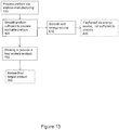
- the method includes a step of preparing (100) a metal shaped-preform via additive manufacturing, followed by forging (200) the metal shaped-preform into a final forged product (e.g., a net-shape product or near net-shape product).
- a final forged product e.g., a net-shape product or near net-shape product.
- the final forged product may require no additional machining or other processing steps, thus facilitating a lower total cost of manufacturing.
- the final forged product may realize improved properties (e.g., relative to a pure additively manufactured component).
- Some non-limiting examples of some properties that may be improved in the final forged product include: fatigue performance, ability to perform non-destructive evaluation including ultrasonic and radiographic inspection, static strength, ductility, and combinations thereof.
- the additive manufacturing step (100) prepares the metal shaped-preform.
- additive manufacturing means a process of joining materials to make objects from 3D model data, usually layer upon layer, as opposed to subtractive manufacturing methodologies, as defined in ASTM F2792-12a for Standard Terminology for Additively Manufacturing Technologies.
- the metal shaped preform may be manufactured via any appropriate additive manufacturing technique described in this ASTM standard, such as binder jetting, directed energy deposition, material extrusion, material jetting, powder bed fusion, digital printing techniques, or sheet lamination, among others. In some embodiments, precisely designed and/or tailored products can be produced.
- the metal shaped-preform produced by the additive manufacturing step (100) is made from any metal suited for both additive manufacturing and forging, including, for example metals or alloys of titanium, aluminum, nickel (e.g., INCONEL), steel, and stainless steel, among others.
- An alloy of titanium is an alloy having titanium as the predominant alloying element.
- An alloy of aluminum is an alloy having aluminum as the predominant alloying element.
- An alloy of nickel is an alloy having nickel as the predominant alloying element.
- An alloy of steel is an alloy having iron as the predominant alloying element, and at least some carbon.
- An alloy of stainless steel is an alloy having iron as the predominant alloying element, at least some carbon, and at least some chromium.
- the metal shaped-preform is an intermediate product in the form of a precursor to a blade for a jet engine.
- the metal shaped-preform is forged (200).
- the forging step (200) uses a single forging step to die forge the metal shaped-preform into the final forged product.
- the forging step (200) uses a single blocker (or metal shaped-preform) to die forge the metal shaped-preform into the final forged product.
- forging (200) the metal shaped-preform configures the final forged product into realizing improved properties, such as improved porosity (e.g., less porosity), improved surface roughness (e.g., less surface roughness, i.e., a smoother surface), and/or better mechanical properties (e.g., improved surface hardness), among others.
- improved porosity e.g., less porosity
- improved surface roughness e.g., less surface roughness, i.e., a smoother surface
- better mechanical properties e.g., improved surface hardness
- the dies and/or tooling of the forging process is at a lower temperature than the metal-shaped preform.
- the forging step includes heating the metal shaped-preform to a stock temperature (the target temperature of the preform prior to the forging) (210), and contacting the metal shaped-preform with a forging die (220).
- the forging die is a temperature that is at least 6°C (10°F) lower than the stock temperature.
- the forging die is a temperature that is at least 14°C (25°F) lower than the stock temperature.
- the forging die when the contacting step (220) is initiated, is a temperature that is at least 28°C (50°F) lower than the stock temperature. In another embodiment, when the contacting step (220) is initiated, the forging die is a temperature that is at least 56°C (100°F) lower than the stock temperature. In yet another embodiment, when the contacting step (220) is initiated, the forging die is a temperature that is at least 111°C (200°F) ower than the stock temperature. In another embodiment, when the contacting step (220) is initiated, the forging die is a temperature that is at least 167°C (300°F) lower than the stock temperature.
- the forging die when the contacting step (220) is initiated, is a temperature that is at least 222°C (400°F) lower than the stock temperature. In another embodiment, when the contacting step (220) is initiated, the forging die is a temperature that is at least 278°C (500°F) lower than the stock temperature. In some embodiments, when the contacting step is initiated, the forging die completes an isothermal forging. In one aspect, after the forging step (200) the final forged product is annealed (300). In some embodiments, the annealing step is configured to achieve desired properties in the final forged product.
- the annealing step (300) facilitates the relieving of residual stress in the metal-shaped preform due to the forging step (200).
- the metal-shaped preform comprises a Ti-6Al-4V alloy and the annealing step (300) comprises heating the final forged product to a temperature of from about 640°C (1184°F) to about 816°C (1500°F) and for a time of from about 0.5 hour to about 5 hours.
- the annealing step (300) comprises heating the final forged product to a temperature of at least about 640°C (1184°F).
- the annealing step (300) comprises heating the final forged product to a temperature of at least about 670°C (1238°F).
- the annealing step (300) comprises heating the final forged product to a temperature of at least about 700°C (1292°F). In another embodiment, the annealing step (300) comprises heating the final forged product to a temperature of not greater than about 760°C (1400°F). In yet another embodiment, the annealing step (300) comprises heating the final forged product to a temperature of not greater than about 750°C (1382°F). In another embodiment, the annealing step (300) comprises heating the final forged product to a temperature of not greater than about 740°C (1364°F). In yet another embodiment, the time is at least about 1 hour. In another embodiment, the time is at least about 2 hours.
- the time is not greater than about 4 hours. In another embodiment, the time is not greater than about 3 hours. In yet another embodiment, the annealing step (300) comprises heating the final forged product to a temperature of about 732°C (1350°F) and for a time of about 2 hours.
- the contacting step (220) comprises applying a sufficient force to the metal shaped-preform via the forging die to realize a pre-selected amount of true strain in the metal shaped-preform.
- the pre-selected amount of strain is varied throughout the finished forging to accommodate, for example, the use of a wrought substrate plate, etc.
- the applying a sufficient force step comprises deforming the metal shaped-preform via the forging die.
- the contacting step (220) comprises applying sufficient force to the metal shaped-preform via the forging die to realize a true strain of from about 0.05 to about 1.10 in the metal shaped-preform. In another embodiment, the contacting step (220) comprises applying sufficient force to the metal shaped-preform via the forging die to realize a true strain of at least 0.10 in the metal shaped-preform. In another embodiment, the contacting step (220) comprises applying sufficient force to the metal shaped-preform via the forging die to realize a true strain of at least 0.20 in the metal shaped-preform.
- the contacting step (220) comprises applying a sufficient force to the metal shaped-preform via the forging die to realize a true strain of at least 0.25 in the metal shaped-preform. In another embodiment, the contacting step (220) comprises applying sufficient force to the metal shaped-preform via the forging die to realize a true strain of at least 0.30 in the metal shaped-preform. In yet another embodiment, the contacting step (220) comprises applying sufficient force to the metal shaped-preform via the forging die to realize a true strain of at least 0.35 in the metal shaped-preform.
- the contacting step (220) comprises applying sufficient force to the metal shaped-preform via the forging die to realize a true strain of not greater than 1.00 in the metal shaped-preform. In yet another embodiment, the contacting step (220) comprises applying sufficient force to the metal shaped-preform via the forging die to realize a true strain of not greater than 0.90 in the metal shaped-preform. In another embodiment, the contacting step (220) comprises applying sufficient force to the metal shaped-preform via the forging die to realize a true strain of not greater than 0.80 in the metal shaped-preform.
- the contacting step (220) comprises applying sufficient force to the metal shaped-preform via the forging die to realize a true strain of not greater than 0.70 in the metal shaped-preform. In another embodiment, the contacting step (220) comprises applying sufficient force to the metal shaped-preform via the forging die to realize a true strain of not greater than 0.60 in the metal shaped-preform. In yet another embodiment, the contacting step (220) comprises applying sufficient force to the metal shaped-preform via the forging die to realize a true strain of not greater than 0.50 in the metal shaped-preform.
- the contacting step (220) comprises applying sufficient force to the metal shaped-preform via the forging die to realize a true strain of not greater than 0.45 in the metal shaped-preform. In yet another embodiment, the contacting step (220) comprises applying sufficient force to the metal shaped-preform via the forging die to realize a true strain of about 0.40 in the metal shaped-preform.
- the metal shaped-preform is a low ductility material, such as a metal matrix composite or an intermetallic material. In one embodiment, the metal shaped-preform is titanium aluminide.
- low ductility material(s) are forged using dies and/or tooling that are at a lower temperature than the low ductility material.
- the forging is absent of isothermal forging (i.e., the forging process does not include isothermal forging), and thus can include any of the stock temperature versus die temperature differentials noted previously.
- the metal shaped preform is a titanium (Ti) alloy, and thus includes titanium as the predominant alloying element.
- a titanium alloy includes at least 48 wt. % Ti.
- a titanium alloy includes at least 49 wt. % Ti.
- a titanium alloy includes at least 50 wt. % Ti.
- the titanium alloy comprises one or more titanium aluminide phases.
- the titanium aluminide phase(s) is/are one or more of Ti 3 Al and TiAl.
- the titanium alloy may include 5-49 wt. % aluminum.
- the titanium aluminide phase(s) comprise TiAl.
- the titanium alloy includes 30-49 wt. % aluminum, and the titanium alloy comprises at least some TiAl. In one embodiment, the titanium aluminide phase(s) comprises Ti 3 Al. In one embodiment, the titanium alloy includes 5-30 wt. % aluminum, and the titanium alloy comprises at least some Ti 3 Al. In one embodiment, the titanium alloy comprises aluminum and vanadium.
- the metal shaped preform comprises a Ti-6Al-4V alloy (a titanium alloy having about 6 wt. % aluminum and about 4 wt. % vanadium).
- the Ti-6Al-4V preforms are heated to a stock temperature of from about 850°C (1562°F) to about 978°C (1792°F).
- the Ti-6Al-4V preforms are heated to a stock temperature of at least 900°C (1652°F).
- the Ti-6Al-4V preforms are heated to a stock temperature of at least 925°C (1697°F).
- the Ti-6Al-4V preforms are heated to a stock temperature of at least 950°C (1742°F).
- the Ti-6AI-4V preforms are heated to a stock temperature of at least 960°C (1760°F). In another embodiment, the Ti-6Al-4V preforms are heated to a stock temperature of not greater than 975°C (1787°F). In yet another embodiment, the Ti-6Al-4V preforms are heated to a stock temperature of not greater than 973°C (1783°F).
- the final forged product is used in the aerospace, aviation, and/or medical industries.
- the final forged product is, for example, a turbine or blade.
- the final forged product is a blade for a jet engine.
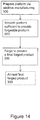
- the metal shaped-preform is forged (200) to create a final forged product. In other embodiments, after the additive manufacturing step (100), the metal shaped-preform is processed via other forms of working (e.g., hot working) to create a final worked product 710.
- other forms of working e.g., hot working
- the working of the metal shaped-preform includes at least one of: rolling 710, ring rolling 720, ring forging 730, shaped rolling 740, and/or extruding 750 to create the final worked product.
- the final worked product realizes improved properties, such as improved porosity (e.g., less porosity), improved surface roughness (e.g., less surface roughness, i.e., a smoother surface), and/or better mechanical properties (e.g., improved surface hardness), among others.
- the final worked product realizes a predetermined shape.
- the metal shaped-preform is ring rolled, ring forged and/or extruded (e.g., forced through a die) to create a hollow final worked product.
- the metal shaped-preform is rolled to produce a final worked product that realizes improved porosity.
- the metal shaped-preform is shape rolled to produce a final worked product that realizes a predetermined shape (e.g., a curve having a specified radius).
- ring rolling means the process of rolling a ring of smaller diameter (e.g., a first ring having a first diameter) into a ring of larger diameter (e.g., a second ring having a second diameter, wherein the second diameter is larger than the first diameter), optionally with a modified cross section (e.g., a cross sectional area of the second ring is different than a cross sectional area of the first ring) by the use of two rotating rollers, one placed in the inside diameter of the ring and the second directly opposite the first on the outside diameter of the ring.
- a modified cross section e.g., a cross sectional area of the second ring is different than a cross sectional area of the first ring
- ring forging means the process of forging a ring of smaller diameter (e.g., a first ring having a first diameter) into a ring of larger diameter (e.g., a second ring having a second diameter, wherein the second diameter is larger than the first diameter), optionally with a modified cross section (e.g., a cross sectional area of the second ring is different than a cross sectional area of the first ring) by squeezing the ring between two tools or dies, one on the inside diameter and one directly opposite on the outside diameter of the ring.
- a modified cross section e.g., a cross sectional area of the second ring is different than a cross sectional area of the first ring
- shaped rolling means the process of shaping or forming by working the piece (i.e., the metal shaped-preform) between two or more rollers, which may or may not be profiled, to impart a curvature or shape to the work piece (i.e., the metal shaped-preform).
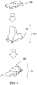
- the step of preparing the metal shaped-preform via additive manufacturing (100) includes incorporating a building substrate into the metal shaped-preform. Referring now to FIG. 5 , one embodiment of incorporating a building substrate
- material (450) is added to a building substrate (400) via additive manufacturing (100) to produce the metal shaped-preform (500).
- building substrate and the like means a solid material (substrate) that is incorporated into a metal shaped-preform.
- the metal shaped-preform (500), which includes the building substrate (400), is forged (200) into a final forged product (600).
- the final forged product (600) includes the building substrate (400) as an integral piece.
- the substrate does not need to be shaped such that it resembles and/or mimics the geometry of the desired deposit or metal shaped-preform.
- the substrate is a rectangular plate on which the additive manufacturing is performed and is machined or otherwise shaped to the desired geometry after additive manufacturing has been performed.
- the substrate is a forging, extrusion, and/or any other material upon which additive manufacturing can be performed.
- additional processing of the metal shaped-preform is performed.
- additional processing includes machining prior to or subsequent to the forging step.
- additional processing includes wire electrical discharge machining (wire EDM) prior to or subsequent to the forging step.
- wire EDM wire electrical discharge machining
- additional processing includes surface finishing prior to or subsequent to the forging step.
- additional processing includes water jet cutting prior to or subsequent to the forging step.
- material extrusion and directed energy deposition are two such classes of additive manufacturing that include start, stop, and bead topography characteristics in the final formed additive part.
- "bead” means a continuous deposit of fused metal (e.g. in an additive manufacturing process).
- directed energy deposition refers to an additive manufacturing process in which a focused thermal energy is used to fuse materials by melting as they are being deposited.
- Non-limiting examples of directed energy deposition include Sciaky, plasma arc, and other wire feed methods.
- material extrusion refers to an additive manufacturing process in which material is selectively dispensed through a nozzle or orifice.
- a "workable preform” means a preform made via additive manufacturing that has suitable characteristics (e.g. acceptable surface finish and/or geometric features) sufficient to undergo working (e.g. hot working).
- a "forgeable preform” means a preform made via additive manufacturing that has suitable characteristics (e.g. acceptable surface finish and/or geometric features) sufficient to undergo forging.
- the specifications for a workable preform and/or forgeable preform with an acceptable surface finish and/or geometric features are dependent on the final part geometry (among other variables).
- the preform is configured to be free of features that would restrict the flow of metal.
- corners on the preforms are configured with appropriate radii (e.g. rounded corners) sufficient for subsequent working to form a worked product (e.g. final forged product).
- the workable preform is configured via one or more embodiments of the instant disclosure, to be substantially free from defects and/or other features (e.g. cracks, gaps, nicks, gouges, sawing serrations, rough portions, ridges, and/or uneven sufraces and other features along a least a portion of the surface) that interrupt a smooth working and/or forging surface.
- the workable preform is configired via one or more embodiments of the instant disclosure, to be substantially free from defects and/or other features such that, when worked (or forged) the resulting final worked product (or final forged product) is substantially free from defects (e.g folds, laps, cavities, non-fill, underfill. and/or other defects).
- some non-limiting examples of defects in the worked final product and/or forged final product include: folds, laps, and/or shuts (e.g. cold shuts).
- fold means a forging defect cased by folding the metal bak on its own surface during its flow in the dis cavity.
- lap means a surface irregularity appearing as a fissure or opening, caused by the folding over of hot metal, fins or sharp corners and by subsequent rolling or forging (but not welding) of these into the surface.
- shuts are faults produced in a forging by incorrect tool design or incorrect flow or metal that results in the formation of a crack in the forging surface.
- cold lap means a flaw that results when a workpiece fails to fill the die cavity during the first forging.
- seam means a formation caused as subsequent dies force metal over a gap to leave a seam on the workpiece surface.
- a “cold shut” is a defect (such as lap) that forms whenever metal folds over itself during forging. As a non-limiting example, cold shuts can occur where vertical and horizontal surfaces intersect.
- these defects can be attributed to surface discontinuities, sharp corners and/or internal features restricting metal flow or otherwise resulting in improper distribution of the metal during a working operation (e.g. forging).
- a working operation e.g. forging
- defeets prior to forging, if defeets are observed in the metal-shaped preform they are addressed to provide a suitable workable preform configured for further working (e.g. forging). This can be done by mechanically smoothing the surface or removing the defect. Mechanical grinding is a typical operation that is used to prepare its and blockers for the forging operation.
- the workable preform (e.g. forgeable preform) is quantified via profilometry techniques (e.g. including contact and/or non-contact analytical methods).
- the workable preform (e.g. forgeable preform) is quantified by measuring the depth to width ration of the valleys along a portion of the surface of the metal shapes perform.
- the preform (e.g, forgeable perform) is quantified by measuring the surface roughness (R A ) along at least a portion of the surface of the metal shaped perform.
- the surface roughness is measured via analytical techniques that are contact methods. In some embodiments, the surface roughness is measured via analytical techniques that are non-contact methods (e.g. blue light seans or white light scans, to name a few).
- the surface of additively manufactured components can be rough (e.g. a plurality of raised ridges indicative of the bead deposition path), or have a periodic or random surface texture, roughness, or morphology, due to the layer-by-layer and bead-by-bead deposition technique used by many of the additive manufacturing technologies.
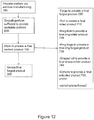
- a method comprising: (a) using additive manufacturing to produce a metal shaped-preform, the metal-shaped preform configured with a plurality of undulations in the surface indicative of an additive manufacturing build;(b) smoothing the plurality of undulations on the surface of the metal shaped-preform via an energy source sufficient to provide a workable preform (or forgeable preform) configured for a further working operation; and (c) working the metal shaped-preform into a final forged
- preparation of the metal shaped-preform includes smoothittg operations to remove undulations in the surface of the part due to the layered structure of the deposit produced using addidve manufacturing processes.
- each layer may consist of a pattern of individual deposits, which may introduce undulations in the surface of the part due to the geometry of the individual deposits.
- the method comprises a smoothing step sufficient to provide surfaces appropriate for working and/or forging (e.g. to avoid defects such as folds and voids).
- surface smoothing techniques include: electron beam smoothing, flash lamp melting, laser melting, are melting, laser ablation, and combination thereof.
- the metal shaped-preforms include smooth edges (e.g. such that the metal-shaped preform. is configured for forging). In some embodiments, the metal shaped-preforms are configured with little to no discontinuous features
- sufficient smoothing to the AM preform results in smooth surfaces and appropriately filled corners and edges such that the mechanical grinding and chipping operations are avoided.
- the using additive manufacturing to build a metal shaped preform includes using a non-powder based additive manufacturing process to build a metal shaped preform.
- the smoothing step comprises using first set of beam parameters to additively manufacture a metal shaped preform (e.g. first beam size, first beam current, first travel speed, first wire feed rate, first beam pattern, and first scan path), followed by adjusting and/or changing to a second set of beam parameters configured for smoothing.
- wire feed is left off for beam smoothing.
- the beam is utilized for removal (burn off) of undesirable material that has collected on the substrate.
- the beam is utilized for preheating the substrate (prior to the using step).
- the using additive manufacturing step comprises additively manufacturing a metal shaped preform via a continuous exterior build plan sufficient to realize a metal shaped-preform capable of further working (e.g. forging) to yield a forged final product.
- depositing the bead (deposited via a continuous exterior build plan) is contipred to promote metal shaped-preform with smooth surface.
- depositing the bead is configured to promote smooth edges in the metal shaped-preform.
- the energy source is the same energy source as the additive manufacturing machine.
- the energy source is an add-on component to the additive manufacturing machine (and not utilized to perform the additive manufacturing step).
- the energy source is a separate piece of equipment from the energy source utilized with the additive manufacturing machine to create the build/deposit of additive feed material.
- the energy source comprises: a laser beam, an electron beam, an are toreh, a plasma torch, flash lamp, a torch, a burner, amongst others, which is used to smooth the surface of an additively manufactured deposit.
- the smoothing step comprises, reducing the surface roughness of a measured portion of the surface of the metal shaped preform.
- the smoothing step comprises reducing the depth to width ratio of the valleys along a measured portion of the surface of the metal shaped-preform.
- the smoothing step comprises reducing the roughness along a measured portion of the metal shaped-preform, as detected with a blue light scan.
- the smoothing step comprises: increasing the temperature of a surface portion of the part in order to promote melting of the uneven surface portion.
- smoothing includes melting, softening, and/or otherwise consolidating at least a portion of the deposited AM path geometry in order to smooth the surface of the metal shape-preform.
- smoothing comprises heating at least a potion of an exterior surface of an AM deposit with an energy source (e.g. to melt, soften, and/or consolidate non-planar surfaces/raised ridges on the metal shaped-preform).
- an energy source e.g. to melt, soften, and/or consolidate non-planar surfaces/raised ridges on the metal shaped-preform.
- smoothing comprises heating (e.g. melting, softening, and/or consolidating) at portion (fraction) of a single bead depth.
- smoothing comprises heating (e.g. melting, softening, and/or consolidating at least two or more bead depths into the metal shaped-perform.
- the surface tension of the melted and/or softened material and/or potential gravitational effects thereof causes any undulations, ripples, and/or dips in the surface of the bead deposit attributable/characteristic fo additive manufacturing to decrease in magnitude.
- the objective of this technique is to melt or soften only the surface of the deposit such that it does not significantly alter the overall shape/geometry of the deposit but removes or reduces localized irregularities in the surface.
- the smoothing step includes (in the case of a deposition of AM material via non-powder bed and/or wire based feeds): defocusing the energy source (e.g. the electron beam of the wire fed AM machine) from a first beam size (e.g. indicative of additive manufacturing) to a second beam size (e.g., indicative of smoothing); rastering the beam into a pattern; and moving over the surface and/or profile of the preform/part to affect smoothing of the surface.
- defocusing the energy source e.g. the electron beam of the wire fed AM machine
- a first beam size e.g. indicative of additive manufacturing
- second beam size e.g., indicative of smoothing
- the size of the rastered beam is maintained over the surface of the part by maintaining the energy source at a set distance from the surface of the part and/or adjusting the amount of defocusing and/or pattern size as a function of the part geometry.
- energy sources include: lasers, ares, and other energy sources are utilized (in lieu of the electron beam) in order to smooth the surface and/or profile of the preform.
- rastering means: moving and/or oscillating the beam in a pattern such that the effective "size" of the beam appears larger in a scan pattern (e.g. of the electron beam in an EBAM machine) in which an area is scanned (e.g. from side-to-side in lines, from top-to-bottom),
- a scan pattern e.g. of the electron beam in an EBAM machine
- the rastered beam may look like 1.27 cm (0.5 inch) in diameter whereas the non-rastered beam may be on the order of 0.254 mm (0.01 inch) in diameter.
- the path that the rastered beam follows around the part is called the scan path.
- the scan path results in the characteristic raised ridges, undulations, and/or surface features perceived/visually observable in the metal shaped preform (e.g. the as built, non-smoothed part).
- the smoothing step is sufficient to provide a surface with a smoothness configured to undergo further working/processing (e.g. forging, ring rolling, extrusion, etc).
- the smoothing step is sufficient to provide a surface with a smoothness configured to undergo further working/processing (e.g. forging, ring rolling, extrusion, etc) without undue machining of the final worked (e.g. forged) product.
- further working/processing e.g. forging, ring rolling, extrusion, etc
- the smoothing step is sufficient to provide a surface with a smoothness configured to undergo further working/processing (e.g. forging, ring rolling, extrusion, etc) without undue machining of the metal shaped-preform prior to further working/processing.
- further working/processing e.g. forging, ring rolling, extrusion, etc
- the smoothing step is sufficient to provide a surface with a smoothness configured to undergo further working/processing (e.g. forging, ring rolling, extrusion, etc) without an undue rejection rate due to defects attributable to additive manufacturing deposition layers.
- the smoothing step is sufficient to reduce the surface roughness of the metal shaped-preform.
- the smoothing step is sufficient to reduce the oscillating surface morphology of an additively manufactured preform via the characteristic ridges interspaced with valleys (e.g. indicative of the pattern of bead deposition/feed patin) of a wire-based additive manufacturing technology.
- the smoothing step is confired to prevent, reduce, and/or eliminate defects (e.g. non-smooth features on the deposits) from the final worked (e.g. forged) product.
- the workable preform has a surface and/or profile that is sufficient to prevent, reduce, and/or eliminate folds, cavities, and/or other undesirable features in the final forged product/final worked product.
- the smoothing step is attributed to an improved manufacturing yield.
- the smoothing step is attributed to improved mechanical properties in the final worked products. In some embodiments, the smoothing step is attributed to reducing undulations in the surface of the deposit, e.g. which can have an improved/enhanced uniformity of the strain achieved in the worked (forged) component.
- the method comprises ultrasonically inspecting the smootbed additive manufacturing preform prior to forging (e.g. and if rejected, remove the part from the production/manufacturing pathway).
- the surface is configured for ultrasonic inspection, enabling identificationof defects to be reworked.
- the smoothing step is followed by an ultrasonically inspecting/detecting step to identify any defects in the metal shaped-preform. If, in this embodiment, one or more defects are identified via ultrasonic inspection, the method further comprises a reworking and/or second smoothing step (e.g. configured to penetrate to a sufficient level to address and ameliorate the detected defect).
- the smoothing step is sufficient to provide a surface capable of ultrasonic inspection without prior machining.
- the preform has an improved configuration for x-ray inspection, enabling identification of defects to be reworked.
- the smoothing step is followed by an x-ray inspecting/detecting step, configured to identify any defects in the metal shaped-preform. If, in this embodiment, one or more defects are identified via x-ray inspection, the method further comprises a reworking and/or second smoothing step (e.g. configured to penetrate to a sufficient level to address and ameliorate the detected defect).
- the smoothing step is sufficient to reduce stress concentrations in the final part (e.g. in instances where the entire surface of the final worked product is not machined).
- the smoothing step melts an upper portion of the part such that the raised ridges on the surface (indicative of an additively manufactured part) are reduced in overall height to provide for a smoothed surface.
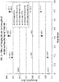
- Table 1 Build Parameters for Each Cylinder Cylinder Wire Diameter (in) Deposition Rate (lbs per hr) Accelerating Voltage (kV) Nominal Beam Current (mA) Surface Travel Speed (IPM) Wire Feed rate (IPM) Target Pool Width (in) 1 0.125 15 40 215 30 127.3 0.47 2 0.125 7.5 40 108 15 63.7 0.47 3 0.045 1 25 85 30 60 02 4 0.125 7.5 40 108 15 63.7 0.47 5 0.045 1 25 85 30 60 02
- Table 2 Dimensions of the Cylinders Cylinder No. ID. In. OD. In. Wall thlckness. In. Height. In. 1 4.85 5.9 0.525 5.8 2 6.0 5.8 0.4 8.2 3 5.5 5.9 0.2 7.5 4 5.0 5.8 0.4 7.1 6 4.9 0.2 7.5
- Cylinders 3 and 5 used the same build parameters, with a wire diameter of 0.045". Cylinder 5 was utilized to demonstrate steps in thickness. While Cylinders 2 and 4 had the same build parameters, it is noted that after building, Cylinder 4 was smoothed with the electron beam according to the following process.
- Figure 17 provides a series of perspective side view photographs of the 5 cylinders. It is visually apparent that there are surface ridges in the as-manufactured metal shaped preforms (without smoothing), i.e. Cylinders 1-3 and 5. Moreover, there are visually observable differences in the surface/profile of cylinders having different diameters of wire feedstock (e.g. depth of ridges, distance of ridges, indicative of the feedstock, deposition rate, and/or other AM parameters.
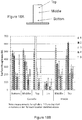
- Figure 18B depicts the measured surface roughness for each of the cylinders (where 18A depicts the relative positioning for each of the measurements along the cylinders).
- surface roughness was characterized along three different areas/portions of the component (i.e. top, middle, and bottom along the inner diameter and outer diameter of the cylinder, where the bottom was configured adjacent to the build substrate).
- Cylinder 4 had the lowest surface roughness for each measured parameter, even though Cylinder 4 was constructed of a larger diameter wire feedstock than Cylinders 3 and 5.
- the lowest RA values were located along the lip (e.g. top) of the cylinders, as compared to the middle and bottom of the cylinders.
- Cylinders 3 and 5 had a generally lower surface roughness than Cylinders 1 and 2, as 3 and 5 had a smaller diameter wire feed stock.
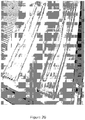
- Figure 19 depicts a cut away side view contrasting the characteristic ridges via the metal shaped-preform of Cylinder 2 (as-made) vs. Cylinder 4, the smoothed surface of a forgeable preform (e.g. workable preform) in accordance with the instant disclosure. Although both cylinders had the same build parameters, the smoothing step reduced the surface roughness of Cylinder 4, to promote a workable preform (e.g. forgeable preform).
- a forgeable preform e.g. workable preform
- a part was additively manufactured utilizing an Electron Beam Additive Manufacturing (EBAM) system (Sciaky).
- EBAM Electron Beam Additive Manufacturing
- the feedstock was a wire of Ti-6Al-4V. Wire was deposited in a layer-by-layer additive method on the substrate plate to create a metal shaped preform.
- the substrate plate dimensions were approximately 12" x 12" x 3/4".
- the electron beam of the additive machine was changed from a deposit mode to a smoothing mode. (No additional feedstock/wire was added to the molten pool and thus no additional material is deposited on the part.)
- the electron beam was defocused, rastered, and moved quickly over the surface of the part at a decreased beam current (e.g., as compared to that used in a standard deposit) to affect smoothins of the surface.
- a low power, defocused electron beam was restered over/moved across the surface of the deposited material in a concentric bulls-eye ring pattern of varying sizes.
- the resulting rastered beam spanned multiple (at least two) deposition paths (e.g. defined by a bead size).
- the resulting rastered beam is the same size as the "build"/deposition beam.
- the resulting rastered beam is smaller than the build/deposition beam.
- the beam in turn caused localized surface heating (e.g.
- the beam current (mA) wets reduced by approwimately half of that in build mode; the travel speed (inches/min) was increased by a little over three times that of the build mode; and the pattern "size" (unitless) was increased from the build mode by a little over 1.5 times.
- the scan path i.e the path that the energy source travels along
- the smoothing pass roughly followed the profile of the part, starting from the center of the part and generally circling outwards (e.g. where the last circle effectively traces the outside of the deposit).
- the "Pattern Size” variable is simply a scaling factor that allows the increase or decrease of the size of the pattern that is projected on the part
- the size of the pattern is variable, based on the initial roughness/waviness of the part, etc.
- the parameters of the energy source are generally interdependent, such that if one variable is modified, the others art also modified accordingly.
- Figure 20 provides a comparison of two different components, contrasting the as built (before smoothing) and the workable preform (after smoothing). More specifically, the photograph on the right is of an as built AM preform that has not undergone EBAM smoothing, white in contrast the photograph on the left is of an AM preform that has undergone EBAM smoothing (e.g. to smooth the ridges characteristic of the deposition pathways along the profile of the preform).
- a metal preform (titanium ar otherwise) is produced using the selected additive manufacturing method (e.g. electron beam additive manufacturing (EBAM), wire are additive manufacturing (WAAM), or other metal deposition or extrusion additive process).
- EBAM electron beam additive manufacturing
- WAAM wire are additive manufacturing
- other metal deposition or extrusion additive process e.g.
- the metal shaped preform is configured with a surface (e.g. reduced ridges, and/or lower surface roughness as compared to a non-smoothed AM surface with the same build paramters) and/or profile (e.g. appropriately filled corners and edges) sufficent to perform a forging operation.
- a surface e.g. reduced ridges, and/or lower surface roughness as compared to a non-smoothed AM surface with the same build paramters
- profile e.g. appropriately filled corners and edges
- This AM produced preform will be the starting stock or blocker for the forging operation.
- the preform is configured to be placed into the forging die (and forged) without further rework. Once prerared, the forgeable preform isplaced in a furnace to heat it to the appropriate forging temperature. The forging dies will also be heated to the appropriate temperature for forging.
- the temperature for both of metal preform (forgeable metal preform) and the forging die are dependent on the type of metal and the geometry (e.g. determined prior to the forging operation).
- the preforms With the dies at the appropriate temperature and the preforms at the appropriate temperature, the preforms will be removed from the furnace and placed within the forging die.
- the forging dies are then compressed together forcing the metal in the preform to redistribute and fill the die cavity. This forging action can occur in a single pressing operation. It may also be accomplished through multiple pressing operations (or blows) until the die impression is filled.
- the process includes heating a prepared preform, forging in the dies, and then the part is then removed from the die and (in some embodiments) is set aside for subsequent operations required for the specific part.
- These subsequent operations could include (as nonlimiting examples): placing back into the furnace for a subsequent forging operation or allowing the part to cool for preparation for other forging steps or thermal operations like heat treating, annealing, and/or aging.
- the subsequent operations include rework operations.
- the cycle of placing a preform in the furnace, heating to the desired temperature, placing in the die for forging, forging to the desired geometry for that step and then removing from the die is considered a forging step.
- a single step forging would be defined as heating and forging the material in a single press with multiple blows.
- a multiple step forging would be defined as repeating the forging step multiple times.
- the final forged product is configured with an amount (e.g., a pre-selected amount) of true strain due to the contacting step 220.
- the strain realized by the final forged product may be non-uniform throughout the final forged product due to, for example, the shape of the forging dies and/or the shape of the metal shaped-preform.
- the final forged product may realize areas of low and/or high strain.
- the building substrate may be located in a predetermined area of the metal shaped-preform such that after the forging, the building substrate is located in a predetermined area of low strain of the final forged product.
- the substrates when the substrates are wrought), the substrates are configured to achieve the desired properties without additional strain.
- an area of low strain is predetermined based on predictive modeling and/or empirical testing.
- the strain distribution within the final forging is predicted.
- the desired amount of strain in the final forging is pre-determined.
- the pre-determined amount of strain is utilized/configured such that the final forged component achieves the desired properties.
- the substrate is configured/located in an area outside of the final component in the forging such that work is not required in that region.
- FIG. 6 another embodiment of incorporating a building substrate (410) into a metal shaped-preform (510) is shown.
- material is added to the building substrate (410) via additive manufacturing (100) to produce the metal shaped-preform (510).
- the metal shaped-preform (510) is forged (200) into a final forged product (610).
- the final forged product (610) includes the building substrate (410) as an integral piece.
- the metal shaped-preform is removed from the building substrate prior to the forging step.
- the building substrate is configured with a predetermined shape and/or predetermined mechanical properties (e.g., strength, toughness to name a few).
- the building substrate is a pre-wrought base plate.
- the shape of the building substrate is predetermined based on the shape of the area of low strain.
- the mechanical properties of the building substrate are predetermined based on the average true strain realized by the metal shaped-preform and/or the true strain realized within the area of low strain.
- two or more building substrates are incorporated into a metal-shaped preform.
- the building substrate comprises a pre-wrought base plate.
- the building substrate was produced using an additive manufacturing process.
- multiple metal shaped-preforms are built upon the same build substrate and separated after the additive manufacturing step and prior to the forging step.
- the building substrate is configured/made from any metal suited for both additive manufacturing and forging, including, for example metals or alloys of titanium, aluminum, nickel (e.g., INCONEL), steel, titanium aluminide, and stainless steel, among others.
- the building substrate is made of the same material(s) as the rest of the metal-shaped preform.
- the material added to the metal shaped preform is a first material
- the building substrate is made of a second material (where the second material is different from the first material).
- the first material is configured with a first strength and the second material is configured with a second strength.
- the first material has a first fatigue property and the second material has a second fatigue property.
- the first material is different form than the second material (e.g. powder on plate, wire on plate, etc.)
- the building substrate is a first ring of a first material.
- a second material is added, via additive manufacturing, to the ring thereby forming a second ring of the second material, integral with the first ring.
- a ring-shaped metal shaped-preform comprising two different materials is produced.
- the ring-shaped metal shaped-preform is then forged into a ring-shaped final forged product comprising two different materials.
- one or more engine containment rings (e.g., one or more aerospace engine containment rings) is formed by the method described above.
- the building substrate includes a first ring of a material which realizes high toughness.
- a second ring of a second material which realizes high strength is added, via additive manufacturing, to the first ring thereby forming a metal shaped-preform.
- the metal shaped-preform is then forged into an engine containment ring having an inner ring of high toughness and outer ring of high strength.
- the resultant metal shaped-preform comprises a gradient structure achieved through the additive manufacturing process by varying the composition of the additive feedstock and/or the process parameters during deposition of the metal shaped-preform.
- Ti-6Al-4V preforms are produced via additive manufacturing. Specifically cylindrical Ti-6Al-4V preforms were produced via an EOSINT M 280 Direct Metal Laser Sintering (DMLS) additive manufacturing system, available from EOS GmbH (Robert-Stirling-Ring 1, 82152 Krailling/Munich, Germany). The Ti-6Al-4V preforms were produced in accordance with the manufacturer's standard recommended operating conditions for titanium. The preforms were then heated to a stock temperature of about 958°C (1756°F) or about 972°C (1782°F).
- DMLS Direct Metal Laser Sintering
- cylindrical preforms were forged under various amounts of true strain and using a die temperature of about 390°C - 400°C (734°F - 752°F) to produce cylindrical final forged products.
- the true strain was applied to the cylindrical preforms in a direction parallel to the axis of the cylinders.
- the remaining preforms were left unforged.
- Some of the final forged products were then annealed at a temperature of about 732°C (1350°F) for approximately two hours to produce annealed final forged products.
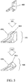
- the forged Ti-6Al-4V products achieved improved properties over the unforged Ti-6Al-4V preforms. Specifically, and with reference to FIG. 3 , the forged Ti-6Al-4V products achieved improved ultimate tensile strength (UTS) over the unforged Ti-6Al-4V preforms. For example, the unforged Ti-6Al-4V preforms achieved a UTS of about 140 ksi. In contrast, the forged Ti-6Al-4V products achieved improved ultimate tensile strength, realizing a UTS of about 149 ksi after being forged to a true strain of about 0.4. Furthermore, and as shown in FIG.
- UTS ultimate tensile strength
- the forged Ti-6Al-4V products achieved improved tensile yield strength (TYS) over the unforged Ti-6Al-4V preforms.
- TYS tensile yield strength
- the unforged Ti-6Al-4V preforms achieved a TYS of about 118 ksi.
- the forged Ti-6Al-4V products achieved improved tensile yield strength, realizing a TYS of about 123 ksi after being forged to a true strain of about 0.4.
- the forged Ti-6Al-4V products achieved good elongation, all achieving an elongation of above 12% after being forged.
- the annealed final forged products achieved improved properties over the final forged products which were not annealed. Specifically, and with reference to FIG. 3 , the annealed final forged products achieved improved tensile yield strength (TYS) over the non-annealed final forged products. For example the annealed final forged products which were forged to a true strain of about 0.2 achieved a TYS approximately 10% higher than the final forged products which were not annealed. Furthermore, and as shown in FIG. 3 , the annealed final forged products achieved similar ultimate tensile strength (UTS) to the non-annealed final forged products. Thus, annealing the final forged products increased TYS without sacrificing UTS. As shown in FIG. 4 , the annealed final forged products achieved improved elongation compared to the non-annealed final forged products.
- UTS ultimate tensile strength
- FIGS. 8-11 are micrographs showing the microstructures of the cylindrical preforms and cylindrical final forged products of Example 1. All of the micrographs were taken in the transverse orientation and at the midpoint of the cylinder.
- FIG. 7 one embodiment of a cylindrical final forged product is illustrated. In the illustrated embodiment, the final forged product has been forged in the Z direction. The X-Y plane shown in FIG. 7 is the transverse orientation and the X-Z plane is the longitudinal orientation.
- a micrograph of a Ti-6Al-4V preform produced via additive manufacturing is shown. As can be seen in FIG. 8 , the microstructure consists of transformed beta phase material with evidence of the prior beta phase grains.
- FIG. 8 the microstructure consists of transformed beta phase material with evidence of the prior beta phase grains.
- FIG. 9 is a micrograph of a additively manufactured Ti-6Al-4V preform that has been preheated to a temperature of about 954°C (1750°F). As can be seen in FIG. 9 , the microstructure after heating is transformed beta phase material with the formation and growth of acicular alpha phase material. No primary alpha phase material is observed.
- FIG. 10 is a micrograph of an additively manufactured Ti-6Al-4V preform that has been preheated to a temperature of about 954°C (1750°F) and then forged to true strain of about 0.7 (e.g., a final forged product). As can be seen in FIG.
- FIG. 11 is a micrograph of an additively manufactured Ti-6Al-4V preform that has been preheated to a temperature of about 954°C (1750°F), then forged to true strain of about 0.7, and then annealed at a temperature of about 732°C (1350°F) (e.g., an annealed final forged product).
- FIG. 11 in addition to the small, circular grains of primary alpha phase material interspersed in the matrix, primary grains of alpha phase material have formed as well.
Landscapes
- Engineering & Computer Science (AREA)
- Mechanical Engineering (AREA)
- Physics & Mathematics (AREA)
- Optics & Photonics (AREA)
- Plasma & Fusion (AREA)
- Chemical & Material Sciences (AREA)
- Materials Engineering (AREA)
- Manufacturing & Machinery (AREA)
- Forging (AREA)
Description
- Generally, the present disclosure is directed towards methods of additively manufacturing metal components. More specifically, the present disclosure is directed towards different embodiments of additively manufacturing and smoothing an AM preform to configure an AM preform for downstream processing (working, forging, and the like).
- Metal products may be formed into shapes via forging operations. To forge metal products, several successive dies (flat dies and/or differently shaped dies) may be used for each part, with the flat die or the die cavity in a first of the dies being designed to deform the forging stock to a first shape defined by the configuration of that particular die, and with the next die being shaped to perform a next successive step in the forging deformation of the stock, and so on, until the final die ultimately gives the forged part a fully deformed shape. See,
U.S. Patent No. 4,055,975 . - Broadly, the present patent application relates to improved methods for producing worked metal products (e.g., forged metal products; other types of hot worked and/or cold worked metal products).
US 2015/013144 A1 , which is considered as the closest prior art to claim 1, discloses a method, comprising using additive manufacturing to produce a metal shaped-preform, wherein the metal shaped-preform comprises a plurality of undulations on a surface of the metal shaped preform indicative of an additive manufacturing build and working the metal shaped-preform to a final worked product. - The invention is defined in appended
claim 1. Preferred embodiments are defined by the appended dependent claims. According to the invention, a method includes using additive manufacturing to produce a metal shaped-preform. After the using step (e.g. producing a metal shaped-preform using/via additive manufacturing), the metal shaped-preform may be forged into a final forged product. In one embodiment, the forging step comprises a single die forging step. In some embodiments, a single forging step is represented by a single heat and forge cycle. In some embodiments, the forge cycle includes multiple deformations without a heating cycle between the deformations. In some embodiments, a heat cycle represents heating the material to the specified temperature prior to the forging deformation step. (As a non-limiting example, a hammer press many times has multiple deformations within a single heat cycle). In one embodiment, the metal preform comprises at least one of titanium, aluminum, nickel, steel, stainless steel, and titanium aluminide. In one embodiment, the metal shaped-preform may be a titanium alloy. For example, the metal shaped-preform may comprise a Ti-6Al-4V alloy. In another embodiment, the metal shaped-preform may be an aluminum alloy. In yet another embodiment, the metal shaped-preform may be a nickel alloy. In yet another embodiment, the metal shaped-preform may be one of a steel and a stainless steel. In another embodiment, the metal shaped-preform may be a metal matrix composite. In yet another embodiment, the metal shaped-preform may comprise titanium aluminide. For example, in one embodiment, the titanium alloy may include at least 48 wt. % Ti and at least one titanium aluminide phase, wherein the at least one titanium aluminide phase is selected from the group consisting of TbAl, TiAl and combinations thereof. In another embodiment, the titanium alloy includes at least 49 wt. % Ti. In yet another embodiment, the titanium alloy includes at least 50 wt. % Ti. In another embodiment, the titanium alloy includes 5-49 wt. % aluminum. In yet another embodiment, the titanium alloy includes 30-49 wt. % aluminum, and the titanium alloy comprises at least some TiAl. In yet another embodiment, the titanium alloy includes 5-30 wt. % aluminum, and the titanium alloy comprises at least some ThAl. - The forging step may comprise heating the metal shaped-preform to a stock temperature, and bringing the metal shaped-preform to the forging die which has been heated separately to the desired temperature, and contacting the metal shaped-preform with a forging die. In one embodiment, the die may be at a temperature that is nominally equal to the metal shaped-preform temperature (e.g. isothermal forging). In another embodiment, when the contacting step is initiated, the forging die may be a temperature that is at least 6°C (10°F) lower than the stock temperature. In another embodiment, when the contacting step is initiated, the forging die is a temperature that is at least 14°C (25°F) lower than the stock temperature. In yet another embodiment, when the contacting step is initiated, the forging die is a temperature that is at least 28°C (50°F) lower than the stock temperature. In another embodiment, when the contacting step is initiated, the forging die is a temperature that is at least 56°C (100°F) lower than the stock temperature. In yet another embodiment, when the contacting step is initiated, the forging die is a temperature that is at least 111°C (200°F) lower than the stock temperature.
- In one aspect, the final forged product is a component for an engine. In one embodiment, the final forged product is a blade for a jet engine. In one embodiment, the final forged product is a component for a vehicle (e.g. land, water, air, and combinations thereof). In one embodiment, the final forged product is a structural component of a vehicle. In another embodiment, the final forged product is a structural aerospace component (e.g. spar, rib, attachment fitting, window frame, landing gear, etc.). In another embodiment, the final forged product is a structural component for a land-based turbine application. In another embodiment, the final forged product is a component for a land-based and/or water-based vehicle. In another embodiment, as described below, the final forged product is an engine containment ring.
- In another aspect, a method comprises using additive manufacturing to produce a metal shaped-preform, and concomitant to, or after the using step, working the metal shaped-preform into a final worked product via at least one of: (i) rolling, (ii) ring rolling, (iii) ring forging, (iv) shape rolling, (v) extruding, and (vi) combinations thereof. In one embodiment, the working is rolling. In another embodiment, the working is ring rolling. In yet another embodiment, the working is ring forging. In another embodiment, the working is shaped rolling. In yet another embodiment, the working is extruding. Without being bound by a particular mechanism or theory, it is believed that one such reason for producing an additively manufactured billet for these processes is to enable (e.g. configure) bi-alloy or multi-alloy starting stock for rolling, forging, or extrusion operations. In some embodiments, the bi-alloy or multi-alloy starting stock is unachievable using conventional billet and starting stock methods.
- In some embodiments, when the metal shaped-preform comprises a Ti-6Al-4V alloy, the forging step comprises heating the metal shaped-preform to a stock temperature, and contacting the metal shaped-preform with a forging die. In this regard, the contacting step comprises deforming the metal shaped-preform via the forging die. In one embodiment, the contacting step comprises deforming the metal shaped-preform via the forging die to realize a true strain of from 0.05 to 1.10 in the metal shaped-preform. In another embodiment, the contacting step comprises deforming the metal shaped-preform via the forging die to realize a true strain of at least 0.10 in the metal shaped-preform. In yet another embodiment, the contacting step comprises deforming the metal shaped-preform via the forging die to realize a true strain of at least 0.20 in the metal shaped-preform. In another embodiment, the contacting step comprises deforming the metal shaped-preform via the forging die to realize a true strain of at least 0.25 in the metal shaped-preform. In yet another embodiment, the contacting step comprises deforming the metal shaped-preform via the forging die to realize a true strain of at least 0.30 in the metal shaped-preform. In another embodiment, the contacting step comprises deforming the metal shaped-preform via the forging die to realize a true strain of at least 0.35 in the metal shaped-preform. In another embodiment, the contacting step comprises deforming the metal shaped-preform via the forging die to realize a true strain of not greater than 1.00 in the metal shaped-preform. In yet another embodiment, the contacting step comprises deforming the metal shaped-preform via the forging die to realize a true strain of not greater than 0.90 in the metal shaped-preform. In another embodiment, the contacting step comprises deforming the metal shaped-preform via the forging die to realize a true strain of not greater than 0.80 in the metal shaped-preform. In yet another embodiment, the contacting step comprises deforming the metal shaped-preform via the forging die to realize a true strain of not greater than 0.70 in the metal shaped-preform. In another embodiment, the contacting step comprises deforming the metal shaped-preform via the forging die to realize a true strain of not greater than 0.60 in the metal shaped-preform. In yet another embodiment, the contacting step comprises deforming the metal shaped-preform via the forging die to realize a true strain of not greater than 0.50 in the metal shaped-preform. In another embodiment, the contacting step comprises deforming the metal shaped-preform via the forging die to realize a true strain of not greater than 0.45 in the metal shaped-preform. As mentioned above, the forging step may comprise heating the metal shaped-preform to a stock temperature.
- In one aspect, the forging step comprises heating the metal-shaped preform to a stock temperature. In one approach, the metal shaped preform is heated to a stock temperature of from 850°C to 978°C. In one embodiment, the metal shaped preform is heated to a stock temperature of at least 900°C. In another embodiment, the metal shaped preform is heated to a stock temperature of at least 950°C. In yet another embodiment, the metal shaped preform is heated to a stock temperature of at least 960°C. In another embodiment, the metal shaped preform is heated to a stock temperature of not greater than 975°C. In yet another embodiment, the metal shaped preform is heated to a stock temperature of not greater than 973°C.
- In one aspect, the step of using additive manufacturing to produce a metal shaped-preform comprises adding material, via additive manufacturing, to a building substrate thereby producing the metal shaped-preform. In some embodiments, a substrate is utilized in additive manufacturing onto which layers are built and/or deposited in order to produce the desired geometry of an additive manufacturing form/product. In one embodiment, the additively manufactured deposit or build is removed from the substrate and comprises the metal shaped-preform. In another embodiment, the substrate or portions of the substrate remains a part of the metal-shaped preform. In one embodiment, the material is a first material having a first strength and wherein the building substrate is comprised of a second material having a second strength. In some embodiments, the first material has a first fatigue property and the second material has a second fatigue property. As a non-limiting example, a layer of a first material having low strength and high toughness could be added, via additive manufacturing, to a building substrate comprised of a second material having high strength and low toughness, thereby producing a metal-shaped preform useful, for example, in ballistic applications. In some embodiments, substrates are selected/tailored/chosen for reasons including (but not limited to): geometry, microstructure, material properties and characteristics, chemistry, cost, amongst others based on (e.g. in order to promote) the design specifications of the finished product. For example, the use of a rolled plate or other wrought substrate allows for reduced and/or minimal work to be utilized in those areas of the metal shaped-preform where the substrate resides due to the substrate already exhibiting forged or wrought properties. In some embodiments, the material and substrate are chosen to be the same.
- In one embodiment, the building substrate comprises a first ring of a first material, and the using step comprises adding a second material, via additive manufacturing, to the first ring thereby forming a second ring, wherein the second ring is integral with the first ring. In this regard, rings consisting of multi-materials are produced.
- In another aspect, the method includes, after the forging step, annealing the final forged product. In one embodiment, when the metal shaped-preform comprises a Ti-6Al-4V alloy, the annealing step comprises heating the final forged product to a temperature of from about 640°C to about 816°C. In another embodiment, when the metal shaped-preform comprises a Ti-6Al-4V alloy, the annealing step comprises heating the final forged product to a temperature of from about 670°C to about 750°C. In yet another embodiment, when the metal shaped-preform comprises a Ti-6Al-4V alloy, the annealing step comprises heating the final forged product to a temperature of from about 700°C to about 740°C. In another embodiment, when the metal shaped-preform comprises a Ti-6Al-4V alloy, the annealing step comprises heating the final forged product to a temperature of about 732°C.
-
-
FIG. 1 is a schematic illustration of a method of producing a final forged product. -
FIG. 2 is a schematic illustration of a method of producing a final forged product, wherein the method includes an optional annealing step. -
FIGS. 3-4 are charts illustrating data of Example 1. -
FIG. 5 is a schematic illustration of one embodiment of a method of producing a final forged product, wherein the final forged product includes an integral building substrate, in accordance with the instant disclosure. -
FIG. 6 is a schematic illustration of another embodiment of a method of producing a final forged product, wherein the final forged product includes an integral building substrate, in accordance with the instant disclosure. -
FIG. 7 is an illustration showing the transverse orientation and longitudinal orientations of a cylindrical preform, in accordance with the instant disclosure. -
FIG. 8 is a micrograph of one embodiment of an as-built Ti-6Al-4V metal shaped-preform, taken in the transverse direction, in accordance with the instant disclosure. -
FIG. 9 is a micrograph of one embodiment of a preheated Ti-6Al-4V metal shaped-preform, taken in the transverse direction, in accordance with the instant disclosure. -
FIG. 10 is a micrograph of one embodiment of a Ti-6Al-4V final forged product, taken in the transverse direction, in accordance with the instant disclosure. -
FIG. 11 is a micrograph of one embodiment of an annealed Ti-6Al-4V final forged product, taken in the transverse direction, in accordance with the instant disclosure. -
Figure 12 is a flow chart depicting an embodiment of a method in accordance with the instant disclosure, in accordance with the instant disclosure. -
Figure 13 depicts a flow chart depicting another embodiment of a method in accordance with the instant disclosure, in accordance with the instant disclosure. -
Figure 14 depicts a flow chart depicting another embodiment of a method in accordance with the instant disclosure, in accordance with the instant disclosure. -
Figure 15 depicts variations on surface topography, illustrating in 15A: a cut away side view of an as-made metal shaped preform (no smoothing); 15B: a smoothed surface providing for reduced surface roughness and/or reduced ratio of valley depth to valley height; 15C: a smoothed surface providing for a greater reduction in surface roughness and ratio of depth to height as compared to 15A or 15B (smoothed) and 15D: an even greater smoothed surface, providing an improved surface roughness and/or ratio of valley depth to height as compared to any of the other iterations (as-made or smoothed) inFigure 15 in accordance with one or more embodiments of the instant disclosure. -
Figure 16 depicts variations on surface topography, illustrating in 16A: a cut away side view of an as-made metal shaped preform (no smoothing); 16B: a smoothed surface providing for reduced surface roughness and/or reduced ratio of valley depth to valley height; 16C: a smoothed surface providing for a greater reduction in surface roughness and ratio of depth to height as compared to 16A or 16B (smoothed) and 16D: an even greater smoothed surface, providing an improved surface roughness and/or ratio of valley depth to height as compared to any of the other iterations (as-made or smoothed) inFigure 16 , in accordance with one or more embodiments of the instant disclosure. -
Figure 17-19 depict photographs and a graph depicting surface roughness for a corresponding Example in the Examples section, in accordance with one or more embodiments of the instant disclosure. -
Figure 20 depicts a side-by-side comparison of an as-made preform compared to an embodiment of a smoothed preform, smoothed in accordance with one or more methods of the instant disclosure. - Reference will now be made in detail to the accompanying drawings, which at least assist in illustrating various pertinent embodiments of the new technology provided for by the present disclosure.
- One embodiment of the new method for producing forged metal products is illustrated in
FIG. 1 . In the illustrated embodiment, the method includes a step of preparing (100) a metal shaped-preform via additive manufacturing, followed by forging (200) the metal shaped-preform into a final forged product (e.g., a net-shape product or near net-shape product). After the forging step (200), the final forged product may require no additional machining or other processing steps, thus facilitating a lower total cost of manufacturing. Furthermore, the final forged product may realize improved properties (e.g., relative to a pure additively manufactured component). Some non-limiting examples of some properties that may be improved in the final forged product (as compared to an AM component with no forging) include: fatigue performance, ability to perform non-destructive evaluation including ultrasonic and radiographic inspection, static strength, ductility, and combinations thereof. - In some embodiments, the additive manufacturing step (100) prepares the metal shaped-preform. As used herein, "additive manufacturing" means a process of joining materials to make objects from 3D model data, usually layer upon layer, as opposed to subtractive manufacturing methodologies, as defined in ASTM F2792-12a for Standard Terminology for Additively Manufacturing Technologies. The metal shaped preform may be manufactured via any appropriate additive manufacturing technique described in this ASTM standard, such as binder jetting, directed energy deposition, material extrusion, material jetting, powder bed fusion, digital printing techniques, or sheet lamination, among others. In some embodiments, precisely designed and/or tailored products can be produced.
- In some embodiments, the metal shaped-preform produced by the additive manufacturing step (100) is made from any metal suited for both additive manufacturing and forging, including, for example metals or alloys of titanium, aluminum, nickel (e.g., INCONEL), steel, and stainless steel, among others. An alloy of titanium is an alloy having titanium as the predominant alloying element. An alloy of aluminum is an alloy having aluminum as the predominant alloying element. An alloy of nickel is an alloy having nickel as the predominant alloying element. An alloy of steel is an alloy having iron as the predominant alloying element, and at least some carbon. An alloy of stainless steel is an alloy having iron as the predominant alloying element, at least some carbon, and at least some chromium. In one embodiment, the metal shaped-preform is an intermediate product in the form of a precursor to a blade for a jet engine.
- Still referring to
FIG. 1 , once the metal shaped-preform is formed, the metal shaped-preform is forged (200). In one embodiment, the forging step (200) uses a single forging step to die forge the metal shaped-preform into the final forged product. In one embodiment, the forging step (200) uses a single blocker (or metal shaped-preform) to die forge the metal shaped-preform into the final forged product. In some embodiments, forging (200) the metal shaped-preform, configures the final forged product into realizing improved properties, such as improved porosity (e.g., less porosity), improved surface roughness (e.g., less surface roughness, i.e., a smoother surface), and/or better mechanical properties (e.g., improved surface hardness), among others. - Referring now to
FIG. 2 , in one embodiment, during the forging step (200), the dies and/or tooling of the forging process is at a lower temperature than the metal-shaped preform. In this regard, the forging step includes heating the metal shaped-preform to a stock temperature (the target temperature of the preform prior to the forging) (210), and contacting the metal shaped-preform with a forging die (220). In one embodiment, when the contacting step (220) is initiated, the forging die is a temperature that is at least 6°C (10°F) lower than the stock temperature. In another embodiment, when the contacting step (220) is initiated, the forging die is a temperature that is at least 14°C (25°F) lower than the stock temperature. In yet another embodiment, when the contacting step (220) is initiated, the forging die is a temperature that is at least 28°C (50°F) lower than the stock temperature. In another embodiment, when the contacting step (220) is initiated, the forging die is a temperature that is at least 56°C (100°F) lower than the stock temperature. In yet another embodiment, when the contacting step (220) is initiated, the forging die is a temperature that is at least 111°C (200°F) ower than the stock temperature. In another embodiment, when the contacting step (220) is initiated, the forging die is a temperature that is at least 167°C (300°F) lower than the stock temperature. In yet another embodiment, when the contacting step (220) is initiated, the forging die is a temperature that is at least 222°C (400°F) lower than the stock temperature. In another embodiment, when the contacting step (220) is initiated, the forging die is a temperature that is at least 278°C (500°F) lower than the stock temperature. In some embodiments, when the contacting step is initiated, the forging die completes an isothermal forging. In one aspect, after the forging step (200) the final forged product is annealed (300). In some embodiments, the annealing step is configured to achieve desired properties in the final forged product. In some embodiments, the annealing step (300) facilitates the relieving of residual stress in the metal-shaped preform due to the forging step (200). In one approach, the metal-shaped preform comprises a Ti-6Al-4V alloy and the annealing step (300) comprises heating the final forged product to a temperature of from about 640°C (1184°F) to about 816°C (1500°F) and for a time of from about 0.5 hour to about 5 hours. In one embodiment, the annealing step (300) comprises heating the final forged product to a temperature of at least about 640°C (1184°F). In another embodiment, the annealing step (300) comprises heating the final forged product to a temperature of at least about 670°C (1238°F). In yet another embodiment, the annealing step (300) comprises heating the final forged product to a temperature of at least about 700°C (1292°F). In another embodiment, the annealing step (300) comprises heating the final forged product to a temperature of not greater than about 760°C (1400°F). In yet another embodiment, the annealing step (300) comprises heating the final forged product to a temperature of not greater than about 750°C (1382°F). In another embodiment, the annealing step (300) comprises heating the final forged product to a temperature of not greater than about 740°C (1364°F). In yet another embodiment, the time is at least about 1 hour. In another embodiment, the time is at least about 2 hours. In yet another embodiment, the time is not greater than about 4 hours. In another embodiment, the time is not greater than about 3 hours. In yet another embodiment, the annealing step (300) comprises heating the final forged product to a temperature of about 732°C (1350°F) and for a time of about 2 hours. - In some embodiments, the contacting step (220) comprises applying a sufficient force to the metal shaped-preform via the forging die to realize a pre-selected amount of true strain in the metal shaped-preform. In some embodiments, the pre-selected amount of strain is varied throughout the finished forging to accommodate, for example, the use of a wrought substrate plate, etc. In one embodiment, the applying a sufficient force step comprises deforming the metal shaped-preform via the forging die. As used herein "true strain" (εtrue) is given by the formula:

- In one embodiment, the metal shaped-preform is a low ductility material, such as a metal matrix composite or an intermetallic material. In one embodiment, the metal shaped-preform is titanium aluminide.
- Without being bound by a particular mechanism or theory, it is believed that using the new processes disclosed herein facilitates more economical production of final forged products from such low ductility materials. As a non-limiting example, with the various embodiments of the foregoing methods, low ductility material(s) are forged using dies and/or tooling that are at a lower temperature than the low ductility material. Thus, in one embodiment, the forging is absent of isothermal forging (i.e., the forging process does not include isothermal forging), and thus can include any of the stock temperature versus die temperature differentials noted previously.
- In one aspect, the metal shaped preform is a titanium (Ti) alloy, and thus includes titanium as the predominant alloying element. In one embodiment, a titanium alloy includes at least 48 wt. % Ti. In another embodiment, a titanium alloy includes at least 49 wt. % Ti. In yet another embodiment, a titanium alloy includes at least 50 wt. % Ti. In one embodiment, the titanium alloy comprises one or more titanium aluminide phases. In one embodiment, the titanium aluminide phase(s) is/are one or more of Ti3Al and TiAl. In some embodiments, when titanium aluminides are present, the titanium alloy may include 5-49 wt. % aluminum. In one embodiment, the titanium aluminide phase(s) comprise TiAl. In one embodiment, the titanium alloy includes 30-49 wt. % aluminum, and the titanium alloy comprises at least some TiAl. In one embodiment, the titanium aluminide phase(s) comprises Ti3Al. In one embodiment, the titanium alloy includes 5-30 wt. % aluminum, and the titanium alloy comprises at least some Ti3Al. In one embodiment, the titanium alloy comprises aluminum and vanadium.
- In one embodiment, the metal shaped preform comprises a Ti-6Al-4V alloy (a titanium alloy having about 6 wt. % aluminum and about 4 wt. % vanadium). In this regard, the Ti-6Al-4V preforms are heated to a stock temperature of from about 850°C (1562°F) to about 978°C (1792°F). In one embodiment, the Ti-6Al-4V preforms are heated to a stock temperature of at least 900°C (1652°F). In another embodiment, the Ti-6Al-4V preforms are heated to a stock temperature of at least 925°C (1697°F). In another embodiment, the Ti-6Al-4V preforms are heated to a stock temperature of at least 950°C (1742°F). In yet another embodiment, the Ti-6AI-4V preforms are heated to a stock temperature of at least 960°C (1760°F). In another embodiment, the Ti-6Al-4V preforms are heated to a stock temperature of not greater than 975°C (1787°F). In yet another embodiment, the Ti-6Al-4V preforms are heated to a stock temperature of not greater than 973°C (1783°F).
- In some embodiments, the final forged product is used in the aerospace, aviation, and/or medical industries. In some embodiments, the final forged product is, for example, a turbine or blade. In one embodiment, the final forged product is a blade for a jet engine.
- In some embodiments, after the additive manufacturing step (100), the metal shaped-preform is forged (200) to create a final forged product. In other embodiments, after the additive manufacturing step (100), the metal shaped-preform is processed via other forms of working (e.g., hot working) to create a final worked product 710.
- In some embodiments, the working of the metal shaped-preform includes at least one of: rolling 710, ring rolling 720, ring forging 730, shaped rolling 740, and/or extruding 750 to create the final worked product. In some embodiments, the final worked product realizes improved properties, such as improved porosity (e.g., less porosity), improved surface roughness (e.g., less surface roughness, i.e., a smoother surface), and/or better mechanical properties (e.g., improved surface hardness), among others. In some embodiments, the final worked product realizes a predetermined shape. In some embodiments, the metal shaped-preform is ring rolled, ring forged and/or extruded (e.g., forced through a die) to create a hollow final worked product. In some embodiments, the metal shaped-preform is rolled to produce a final worked product that realizes improved porosity. In some embodiments, the metal shaped-preform is shape rolled to produce a final worked product that realizes a predetermined shape (e.g., a curve having a specified radius).
- As used herein, "ring rolling" means the process of rolling a ring of smaller diameter (e.g., a first ring having a first diameter) into a ring of larger diameter (e.g., a second ring having a second diameter, wherein the second diameter is larger than the first diameter), optionally with a modified cross section (e.g., a cross sectional area of the second ring is different than a cross sectional area of the first ring) by the use of two rotating rollers, one placed in the inside diameter of the ring and the second directly opposite the first on the outside diameter of the ring.
- As used herein, "ring forging" means the process of forging a ring of smaller diameter (e.g., a first ring having a first diameter) into a ring of larger diameter (e.g., a second ring having a second diameter, wherein the second diameter is larger than the first diameter), optionally with a modified cross section (e.g., a cross sectional area of the second ring is different than a cross sectional area of the first ring) by squeezing the ring between two tools or dies, one on the inside diameter and one directly opposite on the outside diameter of the ring.
- As used herein, "shaped rolling" means the process of shaping or forming by working the piece (i.e., the metal shaped-preform) between two or more rollers, which may or may not be profiled, to impart a curvature or shape to the work piece (i.e., the metal shaped-preform).
- In some embodiments, the step of preparing the metal shaped-preform via additive manufacturing (100) includes incorporating a building substrate into the metal shaped-preform. Referring now to
FIG. 5 , one embodiment of incorporating a building substrate - (400) into the metal shaped-preform (500) is shown. In the illustrated embodiment, material (450) is added to a building substrate (400) via additive manufacturing (100) to produce the metal shaped-preform (500).
- As used herein, "building substrate" and the like means a solid material (substrate) that is incorporated into a metal shaped-preform. In some embodiments, the metal shaped-preform (500), which includes the building substrate (400), is forged (200) into a final forged product (600). Thus, in some embodiments, the final forged product (600) includes the building substrate (400) as an integral piece. In some embodiments, the substrate does not need to be shaped such that it resembles and/or mimics the geometry of the desired deposit or metal shaped-preform. In some embodiments, the substrate is a rectangular plate on which the additive manufacturing is performed and is machined or otherwise shaped to the desired geometry after additive manufacturing has been performed. In some embodiments, the substrate is a forging, extrusion, and/or any other material upon which additive manufacturing can be performed. In some embodiments, additional processing of the metal shaped-preform is performed.
- In some embodiments, additional processing includes machining prior to or subsequent to the forging step.
- In some embodiments, additional processing includes wire electrical discharge machining (wire EDM) prior to or subsequent to the forging step.
- In some embodiments, additional processing includes surface finishing prior to or subsequent to the forging step.
- In some embodiments, additional processing includes water jet cutting prior to or subsequent to the forging step.
- Without being bound by a particular mechanism or theory, it is believed that certain methods of additive manufacturing result in a characteristic topography in the metal shaped-preform (e.g. surface undulations and/or ridges).
- As non-limiting examples, material extrusion and directed energy deposition are two such classes of additive manufacturing that include start, stop, and bead topography characteristics in the final formed additive part. According to the invention, "bead" means a continuous deposit of fused metal (e.g. in an additive manufacturing process).
- As used herein, "directed energy deposition" refers to an additive manufacturing process in which a focused thermal energy is used to fuse materials by melting as they are being deposited. Non-limiting examples of directed energy deposition include Sciaky, plasma arc, and other wire feed methods.
- As used herein, "material extrusion" refers to an additive manufacturing process in which material is selectively dispensed through a nozzle or orifice.
- As used herein, a "workable preform" means a preform made via additive manufacturing that has suitable characteristics (e.g. acceptable surface finish and/or geometric features) sufficient to undergo working (e.g. hot working).
- As used herein, a "forgeable preform" means a preform made via additive manufacturing that has suitable characteristics (e.g. acceptable surface finish and/or geometric features) sufficient to undergo forging.
- In some embodiments, the specifications for a workable preform and/or forgeable preform with an acceptable surface finish and/or geometric features are dependent on the final part geometry (among other variables). In some embodiments, the preform is configured to be free of features that would restrict the flow of metal. In some embodiments, corners on the preforms are configured with appropriate radii (e.g. rounded corners) sufficient for subsequent working to form a worked product (e.g. final forged product).
- In some embodiments, the workable preform is configured via one or more embodiments of the instant disclosure, to be substantially free from defects and/or other features (e.g. cracks, gaps, nicks, gouges, sawing serrations, rough portions, ridges, and/or uneven sufraces and other features along a least a portion of the surface) that interrupt a smooth working and/or forging surface. In some embodiments, the workable preform is configired via one or more embodiments of the instant disclosure, to be substantially free from defects and/or other features such that, when worked (or forged) the resulting final worked product (or final forged product) is substantially free from defects (e.g folds, laps, cavities, non-fill, underfill. and/or other defects).
- some non-limiting examples of defects in the worked final product and/or forged final product include: folds, laps, and/or shuts (e.g. cold shuts). As used herein, "fold" means a forging defect cased by folding the metal bak on its own surface during its flow in the dis cavity. As used herein, "lap" means a surface irregularity appearing as a fissure or opening, caused by the folding over of hot metal, fins or sharp corners and by subsequent rolling or forging (but not welding) of these into the surface. As used herein, "shuts" are faults produced in a forging by incorrect tool design or incorrect flow or metal that results in the formation of a crack in the forging surface. As used herein, "cold lap" means a flaw that results when a workpiece fails to fill the die cavity during the first forging. At used herein, "seam" means a formation caused as subsequent dies force metal over a gap to leave a seam on the workpiece surface. As used herein, a "cold shut" is a defect (such as lap) that forms whenever metal folds over itself during forging. As a non-limiting example, cold shuts can occur where vertical and horizontal surfaces intersect.
- Without being bound by a particular mechanism or theory, these defects can be attributed to surface discontinuities, sharp corners and/or internal features restricting metal flow or otherwise resulting in improper distribution of the metal during a working operation (e.g. forging). Thus, in accordance with one or more of the embodiments of the instant disclosure, prior to forging, if defeets are observed in the metal-shaped preform they are addressed to provide a suitable workable preform configured for further working (e.g. forging). This can be done by mechanically smoothing the surface or removing the defect. Mechanical grinding is a typical operation that is used to prepare its and blockers for the forging operation.
- In one embodiment, the workable preform (e.g. forgeable preform) is quantified via profilometry techniques (e.g. including contact and/or non-contact analytical methods).
- In one embodiment, the workable preform (e.g. forgeable preform) is quantified by measuring the depth to width ration of the valleys along a portion of the surface of the metal shapes perform.
- In one embodiment, the preform (e.g, forgeable perform) is quantified by measuring the surface roughness (RA) along at least a portion of the surface of the metal shaped perform.
- In some embodiments, the surface roughness is measured via analytical techniques that are contact methods. In some embodiments, the surface roughness is measured via analytical techniques that are non-contact methods (e.g. blue light seans or white light scans, to name a few).
- In some embodiments, via the additive manufacturing step, the surface of additively manufactured components can be rough (e.g. a plurality of raised ridges indicative of the bead deposition path), or have a periodic or random surface texture, roughness, or morphology, due to the layer-by-layer and bead-by-bead deposition technique used by many of the additive manufacturing technologies.
- In one embodiment, a method is provided, comprising: (a) using additive manufacturing to produce a metal shaped-preform, the metal-shaped preform configured with a plurality of undulations in the surface indicative of an additive manufacturing build;(b) smoothing the plurality of undulations on the surface of the metal shaped-preform via an energy source sufficient to provide a workable preform (or forgeable preform) configured for a further working operation; and (c) working the metal shaped-preform into a final forged
- In some embodiments, preparation of the metal shaped-preform includes smoothittg operations to remove undulations in the surface of the part due to the layered structure of the deposit produced using addidve manufacturing processes. In some additive manufacturing processes, each layer may consist of a pattern of individual deposits, which may introduce undulations in the surface of the part due to the geometry of the individual deposits.
- In some embodiments, the method comprises a smoothing step sufficient to provide surfaces appropriate for working and/or forging (e.g. to avoid defects such as folds and voids).
- According to the invention, surface smoothing techniques include: electron beam smoothing, flash lamp melting, laser melting, are melting, laser ablation, and combination thereof.
- In some embodiments, the metal shaped-preforms include smooth edges (e.g. such that the metal-shaped preform. is configured for forging). In some embodiments, the metal shaped-preforms are configured with little to no discontinuous features
- In some its with a smoothing step, sufficient smoothing to the AM preform results in smooth surfaces and appropriately filled corners and edges such that the mechanical grinding and chipping operations are avoided.
- In some embodiments, with an additive path smoothing step, sufficient smoothing to the AM preform results in smooth surfaces and appropriately filled corners and edges such that the mechanical grinding and chipping operations are avoided.
- In some embodiments, the using additive manufacturing to build a metal shaped preform includes using a non-powder based additive manufacturing process to build a metal shaped preform. In some embodiments, the smoothing step comprises using first set of beam parameters to additively manufacture a metal shaped preform (e.g. first beam size, first beam current, first travel speed, first wire feed rate, first beam pattern, and first scan path), followed by adjusting and/or changing to a second set of beam parameters configured for smoothing. In some embodiments, wire feed is left off for beam smoothing.
- In some embodiments, the beam is utilized for removal (burn off) of undesirable material that has collected on the substrate.In some embodiments, the beam is utilized for preheating the substrate (prior to the using step).
- In some embodiments, the using additive manufacturing step comprises additively manufacturing a metal shaped preform via a continuous exterior build plan sufficient to realize a metal shaped-preform capable of further working (e.g. forging) to yield a forged final product. In some embodiments, depositing the bead (deposited via a continuous exterior build plan) is contipred to promote metal shaped-preform with smooth surface. In some embodiments, depositing the bead is configured to promote smooth edges in the metal shaped-preform.
- In some embodiments, after the additive manufacturing step, the energy source is the same energy source as the additive manufacturing machine. In some embodiments, the energy source is an add-on component to the additive manufacturing machine (and not utilized to perform the additive manufacturing step). In some embodiments, the energy source is a separate piece of equipment from the energy source utilized with the additive manufacturing machine to create the build/deposit of additive feed material.
- In some embodiments, the energy source comprises: a laser beam, an electron beam, an are toreh, a plasma torch, flash lamp, a torch, a burner, amongst others, which is used to smooth the surface of an additively manufactured deposit.
- In some embodiments, the smoothing step comprises, reducing the surface roughness of a measured portion of the surface of the metal shaped preform.
- In some embodiments, the smoothing step comprises reducing the depth to width ratio of the valleys along a measured portion of the surface of the metal shaped-preform.
- In some embodiments, the smoothing step comprises reducing the roughness along a measured portion of the metal shaped-preform, as detected with a blue light scan.
- In some embodiments, the smoothing step comprises: increasing the temperature of a surface portion of the part in order to promote melting of the uneven surface portion.
- In some embodiments, smoothing includes melting, softening, and/or otherwise consolidating at least a portion of the deposited AM path geometry in order to smooth the surface of the metal shape-preform.
- In some embodiments, smoothing comprises heating at least a potion of an exterior surface of an AM deposit with an energy source (e.g. to melt, soften, and/or consolidate non-planar surfaces/raised ridges on the metal shaped-preform).
- According to the invention, smoothing comprises heating (e.g. melting, softening, and/or consolidating) at portion (fraction) of a single bead depth.
- In some embodiments, smoothing comprises heating (e.g. melting, softening, and/or consolidating at least two or more bead depths into the metal shaped-perform.
- Without being bound by a particular mechanism or theory, it is believed that the surface tension of the melted and/or softened material and/or potential gravitational effects thereof causes any undulations, ripples, and/or dips in the surface of the bead deposit attributable/characteristic fo additive manufacturing to decrease in magnitude. The objective of this technique is to melt or soften only the surface of the deposit such that it does not significantly alter the overall shape/geometry of the deposit but removes or reduces localized irregularities in the surface.
- In some embodiments, the smoothing step includes (in the case of a deposition of AM material via non-powder bed and/or wire based feeds): defocusing the energy source (e.g. the electron beam of the wire fed AM machine) from a first beam size (e.g. indicative of additive manufacturing) to a second beam size (e.g., indicative of smoothing); rastering the beam into a pattern; and moving over the surface and/or profile of the preform/part to affect smoothing of the surface.
- In some embodiments, the size of the rastered beam is maintained over the surface of the part by maintaining the energy source at a set distance from the surface of the part and/or adjusting the amount of defocusing and/or pattern size as a function of the part geometry.
- In embodiments, energy sources include: lasers, ares, and other energy sources are utilized (in lieu of the electron beam) in order to smooth the surface and/or profile of the preform.
- As used herein, "rastering" (e.g. of a beam) means: moving and/or oscillating the beam in a pattern such that the effective "size" of the beam appears larger in a scan pattern (e.g. of the electron beam in an EBAM machine) in which an area is scanned (e.g. from side-to-side in lines, from top-to-bottom), As a non-limiting example, the rastered beam may look like 1.27 cm (0.5 inch) in diameter whereas the non-rastered beam may be on the order of 0.254 mm (0.01 inch) in diameter.
- In some embodiments, the path that the rastered beam follows around the part is called the scan path. For additive manufacturing processes utilizing a wire-based feed, the scan path results in the characteristic raised ridges, undulations, and/or surface features perceived/visually observable in the metal shaped preform (e.g. the as built, non-smoothed part).
- In some embodiments, the smoothing step is sufficient to provide a surface with a smoothness configured to undergo further working/processing (e.g. forging, ring rolling, extrusion, etc).
- In some embodiments, the smoothing step is sufficient to provide a surface with a smoothness configured to undergo further working/processing (e.g. forging, ring rolling, extrusion, etc) without undue machining of the final worked (e.g. forged) product.
- In some embodiments, the smoothing step is sufficient to provide a surface with a smoothness configured to undergo further working/processing (e.g. forging, ring rolling, extrusion, etc) without undue machining of the metal shaped-preform prior to further working/processing.
- In some embodiments, the smoothing step is sufficient to provide a surface with a smoothness configured to undergo further working/processing (e.g. forging, ring rolling, extrusion, etc) without an undue rejection rate due to defects attributable to additive manufacturing deposition layers.
- In some embodiments, the smoothing step is sufficient to reduce the surface roughness of the metal shaped-preform.
- In some embodiments, the smoothing step is sufficient to reduce the oscillating surface morphology of an additively manufactured preform via the characteristic ridges interspaced with valleys (e.g. indicative of the pattern of bead deposition/feed patin) of a wire-based additive manufacturing technology.
- In some embodiments, the smoothing step is confired to prevent, reduce, and/or eliminate defects (e.g. non-smooth features on the deposits) from the final worked (e.g. forged) product. In some embodiments, the workable preform has a surface and/or profile that is sufficient to prevent, reduce, and/or eliminate folds, cavities, and/or other undesirable features in the final forged product/final worked product.
- In some embodiments, the smoothing step is attributed to an improved manufacturing yield.
- In some embodiments, the smoothing step is attributed to improved mechanical properties in the final worked products. In some embodiments, the smoothing step is attributed to reducing undulations in the surface of the deposit, e.g. which can have an improved/enhanced uniformity of the strain achieved in the worked (forged) component.
- In some embodiments, after the smoothing step, the method comprises ultrasonically inspecting the smootbed additive manufacturing preform prior to forging (e.g. and if rejected, remove the part from the production/manufacturing pathway).
- In some embodiments, after the smoothing step, the surface is configured for ultrasonic inspection, enabling identificationof defects to be reworked. In this embodiment, the smoothing step is followed by an ultrasonically inspecting/detecting step to identify any defects in the metal shaped-preform. If, in this embodiment, one or more defects are identified via ultrasonic inspection, the method further comprises a reworking and/or second smoothing step (e.g. configured to penetrate to a sufficient level to address and ameliorate the detected defect).
- In some embodiments, the smoothing step is sufficient to provide a surface capable of ultrasonic inspection without prior machining.
- In some embodiments, after the smoothing step, the preform has an improved configuration for x-ray inspection, enabling identification of defects to be reworked. In this embodiment, the smoothing step is followed by an x-ray inspecting/detecting step, configured to identify any defects in the metal shaped-preform. If, in this embodiment, one or more defects are identified via x-ray inspection, the method further comprises a reworking and/or second smoothing step (e.g. configured to penetrate to a sufficient level to address and ameliorate the detected defect).
- In some embodiments, the smoothing step is sufficient to reduce stress concentrations in the final part (e.g. in instances where the entire surface of the final worked product is not machined).
- Without being bound by a particular mechanism or theory, it is believed that the smoothing step melts an upper portion of the part such that the raised ridges on the surface (indicative of an additively manufactured part) are reduced in overall height to provide for a smoothed surface.
- Five cylinders were additively manufactured from Ti-6Al-4V using electron beam additive manufacturing (Sciaky). Build parameters were varied and one of the cylinders was surface smoothed using ebeam smoothing. The build parameters are outlined in Table 1, while the final part dimensions are outlined in Table 2 (below). The experimental results are provided in
Figure 17-19 , which include photographs of the cylinders and a chart depicting surface roughness.Table 1: Build Parameters for Each Cylinder Cylinder Wire Diameter (in) Deposition Rate (lbs per hr) Accelerating Voltage (kV) Nominal Beam Current (mA) Surface Travel Speed (IPM) Wire Feed rate (IPM) Target Pool Width (in) 1 0.125 15 40 215 30 127.3 0.47 2 0.125 7.5 40 108 15 63.7 0.47 3 0.045 1 25 85 30 60 02 4 0.125 7.5 40 108 15 63.7 0.47 5 0.045 1 25 85 30 60 02 Table 2: Dimensions of the Cylinders Cylinder No. ID. In. OD. In. Wall thlckness. In. Height. In. 1 4.85 5.9 0.525 5.8 2 6.0 5.8 0.4 8.2 3 5.5 5.9 0.2 7.5 4 5.0 5.8 0.4 7.1 6 4.9 5.3 0.2 7.5 -
Cylinders Cylinder 5 was utilized to demonstrate steps in thickness. WhileCylinders Cylinder 4 was smoothed with the electron beam according to the following process. -
Figure 17 provides a series of perspective side view photographs of the 5 cylinders. It is visually apparent that there are surface ridges in the as-manufactured metal shaped preforms (without smoothing), i.e. Cylinders 1-3 and 5. Moreover, there are visually observable differences in the surface/profile of cylinders having different diameters of wire feedstock (e.g. depth of ridges, distance of ridges, indicative of the feedstock, deposition rate, and/or other AM parameters. -
Figure 18B depicts the measured surface roughness for each of the cylinders (where 18A depicts the relative positioning for each of the measurements along the cylinders). For each of the 5 cylinders, surface roughness was characterized along three different areas/portions of the component (i.e. top, middle, and bottom along the inner diameter and outer diameter of the cylinder, where the bottom was configured adjacent to the build substrate). Referring to the graph ofFigure 18B ,Cylinder 4 had the lowest surface roughness for each measured parameter, even thoughCylinder 4 was constructed of a larger diameter wire feedstock thanCylinders Cylinders Cylinders -
Figure 19 depicts a cut away side view contrasting the characteristic ridges via the metal shaped-preform of Cylinder 2 (as-made) vs.Cylinder 4, the smoothed surface of a forgeable preform (e.g. workable preform) in accordance with the instant disclosure. Although both cylinders had the same build parameters, the smoothing step reduced the surface roughness ofCylinder 4, to promote a workable preform (e.g. forgeable preform). - A part was additively manufactured utilizing an Electron Beam Additive Manufacturing (EBAM) system (Sciaky). The feedstock was a wire of Ti-6Al-4V. Wire was deposited in a layer-by-layer additive method on the substrate plate to create a metal shaped preform. The substrate plate dimensions were approximately 12" x 12" x 3/4".
- Once the metal shaped preform was built, the electron beam of the additive machine was changed from a deposit mode to a smoothing mode. (No additional feedstock/wire was added to the molten pool and thus no additional material is deposited on the part.) During smoothing, the electron beam was defocused, rastered, and moved quickly over the surface of the part at a decreased beam current (e.g., as compared to that used in a standard deposit) to affect smoothins of the surface.
- During smoothing, a low power, defocused electron beam was restered over/moved across the surface of the deposited material in a concentric bulls-eye ring pattern of varying sizes. In some embodiments, the resulting rastered beam spanned multiple (at least two) deposition paths (e.g. defined by a bead size). In some embodiments, the resulting rastered beam is the same size as the "build"/deposition beam. In some embodiments, the resulting rastered beam is smaller than the build/deposition beam. The beam in turn caused localized surface heating (e.g. melting and/or softening) which allowed the ridged material (indicative of the various paths of bead deposition) to flow towards the valleys and reduce the overall surface waviness/characteristics of at least a portion (e.g. treated portion) of the preform.
- More specifically, in comparing the beam parameters for the building step vs. the smoothing step, for the smoothing step, the beam current (mA) wets reduced by approwimately half of that in build mode; the travel speed (inches/min) was increased by a little over three times that of the build mode; and the pattern "size" (unitless) was increased from the build mode by a little over 1.5 times.
- It is noted that the same beam pattern was atilized in both the AM building step and the smoothing step. The scan path (i.e the path that the energy source travels along) for the standard deposit (building) was completed in a series of parallel lines, while the smoothing pass roughly followed the profile of the part, starting from the center of the part and generally circling outwards (e.g. where the last circle effectively traces the outside of the deposit). The "Pattern Size" variable is simply a scaling factor that allows the increase or decrease of the size of the pattern that is projected on the part The size of the pattern is variable, based on the initial roughness/waviness of the part, etc. The parameters of the energy source (electron beam) are generally interdependent, such that if one variable is modified, the others art also modified accordingly.
-
Figure 20 provides a comparison of two different components, contrasting the as built (before smoothing) and the workable preform (after smoothing). More specifically, the photograph on the right is of an as built AM preform that has not undergone EBAM smoothing, white in contrast the photograph on the left is of an AM preform that has undergone EBAM smoothing (e.g. to smooth the ridges characteristic of the deposition pathways along the profile of the preform). - A metal preform (titanium ar otherwise) is produced using the selected additive manufacturing method (e.g. electron beam additive manufacturing (EBAM), wire are additive manufacturing (WAAM), or other metal deposition or extrusion additive process).
- With the proper smoothing (e.g. via a energy source). the metal shaped preform is configured with a surface (e.g. reduced ridges, and/or lower surface roughness as compared to a non-smoothed AM surface with the same build paramters) and/or profile (e.g. appropriately filled corners and edges) sufficent to perform a forging operation. With the metal shaped-preform configure as a forgeable preform, additional precessing steps (including but not limited to) mechanical grinding and/or chipping operations are reduced, prevented, and/or eliminated.
- This AM produced preform will be the starting stock or blocker for the forging operation. The preform is configured to be placed into the forging die (and forged) without further rework. Once prerared, the forgeable preform isplaced in a furnace to heat it to the appropriate forging temperature. The forging dies will also be heated to the appropriate temperature for forging. The temperature for both of metal preform (forgeable metal preform) and the forging die are dependent on the type of metal and the geometry (e.g. determined prior to the forging operation).
- With the dies at the appropriate temperature and the preforms at the appropriate temperature, the preforms will be removed from the furnace and placed within the forging die. The forging dies are then compressed together forcing the metal in the preform to redistribute and fill the die cavity. This forging action can occur in a single pressing operation. It may also be accomplished through multiple pressing operations (or blows) until the die impression is filled.
- The process includes heating a prepared preform, forging in the dies, and then the part is then removed from the die and (in some embodiments) is set aside for subsequent operations required for the specific part. These subsequent operations could include (as nonlimiting examples): placing back into the furnace for a subsequent forging operation or allowing the part to cool for preparation for other forging steps or thermal operations like heat treating, annealing, and/or aging. In some embodiments, the subsequent operations include rework operations. The cycle of placing a preform in the furnace, heating to the desired temperature, placing in the die for forging, forging to the desired geometry for that step and then removing from the die is considered a forging step. A single step forging would be defined as heating and forging the material in a single press with multiple blows. A multiple step forging would be defined as repeating the forging step multiple times.
- In some embodiments, the final forged product is configured with an amount (e.g., a pre-selected amount) of true strain due to the contacting
step 220. In some embodiments, the strain realized by the final forged product may be non-uniform throughout the final forged product due to, for example, the shape of the forging dies and/or the shape of the metal shaped-preform. Thus, the final forged product may realize areas of low and/or high strain. Accordingly, the building substrate may be located in a predetermined area of the metal shaped-preform such that after the forging, the building substrate is located in a predetermined area of low strain of the final forged product. In some embodiments (e.g. when the substrates are wrought), the substrates are configured to achieve the desired properties without additional strain. In some embodiments, an area of low strain is predetermined based on predictive modeling and/or empirical testing. In some embodiments, based on modeling, the strain distribution within the final forging is predicted. In some embodiments, through design and analysis of the metal shaped-preform, the desired amount of strain in the final forging is pre-determined. In some embodiments, the pre-determined amount of strain is utilized/configured such that the final forged component achieves the desired properties. As such, the substrate is configured/located in an area outside of the final component in the forging such that work is not required in that region. - Referring now to
FIG. 6 , another embodiment of incorporating a building substrate (410) into a metal shaped-preform (510) is shown. In the illustrated embodiment, material is added to the building substrate (410) via additive manufacturing (100) to produce the metal shaped-preform (510). In this embodiment, the metal shaped-preform (510) is forged (200) into a final forged product (610). In this embodiment, the final forged product (610) includes the building substrate (410) as an integral piece. In another embodiment, the metal shaped-preform is removed from the building substrate prior to the forging step. - In some embodiments, the building substrate is configured with a predetermined shape and/or predetermined mechanical properties (e.g., strength, toughness to name a few). In one embodiment, the building substrate is a pre-wrought base plate. In one embodiment, the shape of the building substrate is predetermined based on the shape of the area of low strain. In one embodiment, the mechanical properties of the building substrate are predetermined based on the average true strain realized by the metal shaped-preform and/or the true strain realized within the area of low strain. In one embodiment, two or more building substrates are incorporated into a metal-shaped preform. In one embodiment, the building substrate comprises a pre-wrought base plate. In one embodiment, the building substrate was produced using an additive manufacturing process. In one embodiment, multiple metal shaped-preforms are built upon the same build substrate and separated after the additive manufacturing step and prior to the forging step.
- In some embodiments, the building substrate is configured/made from any metal suited for both additive manufacturing and forging, including, for example metals or alloys of titanium, aluminum, nickel (e.g., INCONEL), steel, titanium aluminide, and stainless steel, among others. In one embodiment, the building substrate is made of the same material(s) as the rest of the metal-shaped preform. In one embodiment, the material added to the metal shaped preform is a first material, whereas the building substrate is made of a second material (where the second material is different from the first material). In one embodiment, the first material is configured with a first strength and the second material is configured with a second strength. In one embodiment, the first material has a first fatigue property and the second material has a second fatigue property. In some embodiments, the first material is different form than the second material (e.g. powder on plate, wire on plate, etc.)
- In one example, the building substrate is a first ring of a first material. A second material is added, via additive manufacturing, to the ring thereby forming a second ring of the second material, integral with the first ring. Thus, a ring-shaped metal shaped-preform comprising two different materials is produced. In this example, the ring-shaped metal shaped-preform is then forged into a ring-shaped final forged product comprising two different materials.
- In one embodiment, one or more engine containment rings (e.g., one or more aerospace engine containment rings) is formed by the method described above. For example, the building substrate includes a first ring of a material which realizes high toughness. Then, a second ring of a second material which realizes high strength is added, via additive manufacturing, to the first ring thereby forming a metal shaped-preform. In this embodiment, the metal shaped-preform is then forged into an engine containment ring having an inner ring of high toughness and outer ring of high strength.
- In some embodiments, additive manufacturing is utilized to produce gradient materials. In this embodiment, the resultant metal shaped-preform comprises a gradient structure achieved through the additive manufacturing process by varying the composition of the additive feedstock and/or the process parameters during deposition of the metal shaped-preform.
- Several Ti-6Al-4V preforms are produced via additive manufacturing. Specifically cylindrical Ti-6Al-4V preforms were produced via an EOSINT M 280 Direct Metal Laser Sintering (DMLS) additive manufacturing system, available from EOS GmbH (Robert-Stirling-
Ring 1, 82152 Krailling/Munich, Germany). The Ti-6Al-4V preforms were produced in accordance with the manufacturer's standard recommended operating conditions for titanium. The preforms were then heated to a stock temperature of about 958°C (1756°F) or about 972°C (1782°F). Next, some of the cylindrical preforms were forged under various amounts of true strain and using a die temperature of about 390°C - 400°C (734°F - 752°F) to produce cylindrical final forged products. The true strain was applied to the cylindrical preforms in a direction parallel to the axis of the cylinders. The remaining preforms were left unforged. Some of the final forged products were then annealed at a temperature of about 732°C (1350°F) for approximately two hours to produce annealed final forged products. Mechanical properties of the unforged preforms, the final forged products, and the annealed final forged products were then tested, including tensile yield strength (TYS), ultimate tensile strength (UTS) and elongation, all in the L direction, the results of which are shown inFIGS 3-4 . For each level of strain, several samples were tested and the results were averaged. Mechanical properties, including TYS, UTS, and elongation were tested in accordance with ASTM E8. - As shown, the forged Ti-6Al-4V products achieved improved properties over the unforged Ti-6Al-4V preforms. Specifically, and with reference to
FIG. 3 , the forged Ti-6Al-4V products achieved improved ultimate tensile strength (UTS) over the unforged Ti-6Al-4V preforms. For example, the unforged Ti-6Al-4V preforms achieved a UTS of about 140 ksi. In contrast, the forged Ti-6Al-4V products achieved improved ultimate tensile strength, realizing a UTS of about 149 ksi after being forged to a true strain of about 0.4. Furthermore, and as shown inFIG. 3 , the forged Ti-6Al-4V products achieved improved tensile yield strength (TYS) over the unforged Ti-6Al-4V preforms. For example, the unforged Ti-6Al-4V preforms achieved a TYS of about 118 ksi. In contrast, the forged Ti-6Al-4V products achieved improved tensile yield strength, realizing a TYS of about 123 ksi after being forged to a true strain of about 0.4. As shown inFIG. 4 , the forged Ti-6Al-4V products achieved good elongation, all achieving an elongation of above 12% after being forged. - Furthermore, the annealed final forged products achieved improved properties over the final forged products which were not annealed. Specifically, and with reference to
FIG. 3 , the annealed final forged products achieved improved tensile yield strength (TYS) over the non-annealed final forged products. For example the annealed final forged products which were forged to a true strain of about 0.2 achieved a TYS approximately 10% higher than the final forged products which were not annealed. Furthermore, and as shown inFIG. 3 , the annealed final forged products achieved similar ultimate tensile strength (UTS) to the non-annealed final forged products. Thus, annealing the final forged products increased TYS without sacrificing UTS. As shown inFIG. 4 , the annealed final forged products achieved improved elongation compared to the non-annealed final forged products. -
FIGS. 8-11 are micrographs showing the microstructures of the cylindrical preforms and cylindrical final forged products of Example 1. All of the micrographs were taken in the transverse orientation and at the midpoint of the cylinder. Referring now toFIG. 7 , one embodiment of a cylindrical final forged product is illustrated. In the illustrated embodiment, the final forged product has been forged in the Z direction. The X-Y plane shown inFIG. 7 is the transverse orientation and the X-Z plane is the longitudinal orientation. Referring back toFIG. 8 , a micrograph of a Ti-6Al-4V preform produced via additive manufacturing is shown. As can be seen inFIG. 8 , the microstructure consists of transformed beta phase material with evidence of the prior beta phase grains.FIG. 9 is a micrograph of a additively manufactured Ti-6Al-4V preform that has been preheated to a temperature of about 954°C (1750°F). As can be seen inFIG. 9 , the microstructure after heating is transformed beta phase material with the formation and growth of acicular alpha phase material. No primary alpha phase material is observed.FIG. 10 is a micrograph of an additively manufactured Ti-6Al-4V preform that has been preheated to a temperature of about 954°C (1750°F) and then forged to true strain of about 0.7 (e.g., a final forged product). As can be seen inFIG. 10 the preheating and forging steps result in a more refined grain structure, punctuated by the nucleation of primary alpha phase grains interspersed in the matrix. These interspersed primary alpha phase grains are observed as the small, white, circular dots.FIG. 11 is a micrograph of an additively manufactured Ti-6Al-4V preform that has been preheated to a temperature of about 954°C (1750°F), then forged to true strain of about 0.7, and then annealed at a temperature of about 732°C (1350°F) (e.g., an annealed final forged product). As can be seen inFIG. 11 , in addition to the small, circular grains of primary alpha phase material interspersed in the matrix, primary grains of alpha phase material have formed as well. - While various embodiments of the present disclosure have been described in detail, it is apparent that modification and adaptations of those embodiments will occur to those skilled in the art. However, it is to be expressly understood that such modifications and adaptations are within the scope of the appended claims.
Claims (15)
- A method, comprising:a. using additive manufacturing (100) to produce a metal shaped-preform, wherein the metal shaped-preform comprises a plurality of undulations on a surface of the metal shaped preform indicative of an additive manufacturing build;b. smoothing (800) the plurality of undulations on the surface of the metal shaped-preform via an energy source sufficient to provide a workable preform configured for a further working operation,
wherein smoothing comprises at least one of: electron beam smoothing, flash lamp melting, laser melting, arc melting, laser ablation, and combinations thereof, and wherein the smoothing comprises heating at least a portion of a single bead depth, wherein a bead is a continuous deposit of fused metal; andc. working (700) the metal shaped-preform to a final worked product. - The method of claim 1, wherein the final worked product is free from defects including folds and voids due to the smoothing step.
- The method of claim 1, wherein the metal shaped-preform comprises smooth outer edges.
- The method of any preceding claim, wherein the using step includes using a non-powder based additive manufacturing process to build a metal shaped preform.
- The method of any preceding claim, further comprising using a first set of beam parameters to additively manufacture a metal shaped preform during the additive manufacturing step, followed by changing to a second set of beam parameters configured for smoothing, wherein a set of beam parameters comprises a plurality of beam variables, and preferably wherein the beam variables include:beam size, beam current, travel speed, wire feed rate, beam pattern, scan path, andcombinations thereof, and more preferably wherein the first set of beam parameters differ from the second set of beam parameters by a difference in at least one beam variable, and most preferably wherein the wire feed rate is 0 during smoothing.
- The method of any preceding claim, comprising preheating a substrate with the energy source before the using step.
- The method of any preceding claim, wherein the using additive manufacturing step comprises additively manufacturing a metal shaped preform via a continuous build plan, and preferably wherein the using additive manufacturing step comprises additively manufacturing a metal shaped preform via a continuous exterior build plan.
- The method of any preceding claim, wherein the using step involves an energy source and wherein the energy source for the using step is the same energy source as for the smoothing step.
- The method of any preceding claim, wherein smoothing comprises, reducing a surface roughness of a measured portion of the surface of the metal shaped preform, and preferably wherein the smoothing step comprises reducing the roughness along a measured portion of the metal shaped-preform, as detected with a blue light scan.
- The method of any preceding claim, wherein the smoothing step comprises reducing a depth to width ratio of valleys along a measured portion of the surface of the metal shaped-preform.
- The method of any preceding claim, wherein the smoothing step comprises:
increasing a temperature of a surface portion of the metal shaped preform in order to promote melting of the surface portion. - The method of any preceding claim, wherein smoothing includes at least one of: melting, softening, and consolidating at least a portion of the deposited additive manufacturing path geometry in order to smooth the surface of the metal shaped-preform.
- The method of any preceding claim, wherein smoothing comprises heating at least a portion of an exterior surface of an additive manufacturing deposit with an energy source, and/or wherein smoothing comprises heating at least two or more bead depths into the metal shaped-preform.
- The method of any preceding claim, wherein the using step involves an energy source and wherein the smoothing step comprises:a. defocusing the energy source from a first beam size of the energy source deployed in the using step to a second beam size for smoothing;b. rastering the beam into a pattern; andc. moving over the surface of the preform to affect smoothing of the surface.
- The method of any preceding claim, wherein the working step is selected from the group consisting of:a. forging,b. rolling,c. ring rolling,d. extruding, ande. combinations thereof.
Applications Claiming Priority (2)
| Application Number | Priority Date | Filing Date | Title |
|---|---|---|---|
| US201662278753P | 2016-01-14 | 2016-01-14 | |
| PCT/US2017/013504 WO2017123995A1 (en) | 2016-01-14 | 2017-01-13 | Methods for producing forged products and other worked products |
Publications (2)
| Publication Number | Publication Date |
|---|---|
| EP3402619A1 EP3402619A1 (en) | 2018-11-21 |
| EP3402619B1 true EP3402619B1 (en) | 2020-12-23 |
Family
ID=58057221
Family Applications (1)
| Application Number | Title | Priority Date | Filing Date |
|---|---|---|---|
| EP17705984.7A Active EP3402619B1 (en) | 2016-01-14 | 2017-01-13 | Methods for producing forged products and other worked products |
Country Status (6)
| Country | Link |
|---|---|
| US (1) | US11554443B2 (en) |
| EP (1) | EP3402619B1 (en) |
| CN (1) | CN108472712A (en) |
| CA (1) | CA3011463C (en) |
| RU (1) | RU2702888C1 (en) |
| WO (1) | WO2017123995A1 (en) |
Families Citing this family (10)
| Publication number | Priority date | Publication date | Assignee | Title |
|---|---|---|---|---|
| WO2011034985A1 (en) | 2009-09-17 | 2011-03-24 | Sciaky, Inc. | Electron beam layer manufacturing |
| WO2011123195A1 (en) | 2010-03-31 | 2011-10-06 | Sciaky, Inc. | Raster methodology, apparatus and system for electron beam layer manufacturing using closed loop control |
| CN108472712A (en) | 2016-01-14 | 2018-08-31 | 奥科宁克公司 | Method for producing forging product and other converted products |
| US10933981B2 (en) * | 2016-06-21 | 2021-03-02 | Goodrich Corporation | Aerodynamic noise reducing thin-skin landing gear structures and manufacturing techniques |
| DE102018108145A1 (en) * | 2018-04-06 | 2019-10-10 | Volkswagen Ag | Method for processing surfaces of components produced by means of 3D printing, and such a machined component |
| US11123820B2 (en) * | 2018-06-21 | 2021-09-21 | Florida Turbine Technologies, Inc. | Process of forming a metal additive manufactured part with a smooth surface |
| CN109434264A (en) * | 2018-10-26 | 2019-03-08 | 中国航发北京航空材料研究院 | Large scale metal annular members electron beam fuse increases material base+looping mill rolling manufacturing process |
| CN109590420A (en) * | 2018-12-21 | 2019-04-09 | 西南铝业(集团)有限责任公司 | A kind of contour forging technique method of aircraft Main joint |
| RU2725537C1 (en) * | 2019-12-31 | 2020-07-02 | федеральное государственное бюджетное образовательное учреждение высшего образования "Национальный исследовательский университет "МЭИ" (ФГБОУ ВО "НИУ "МЭИ") | Method for electron-beam additive production of workpieces |
| CN115319420A (en) * | 2022-08-29 | 2022-11-11 | 中国电子科技集团公司第十四研究所 | Manufacturing method of titanium alloy disc type part based on electric arc additive |
Family Cites Families (146)
| Publication number | Priority date | Publication date | Assignee | Title |
|---|---|---|---|---|
| GB1517283A (en) | 1974-06-28 | 1978-07-12 | Singer Alec | Production of metal articles |
| US4055975A (en) * | 1977-04-01 | 1977-11-01 | Lockheed Aircraft Corporation | Precision forging of titanium |
| US4294615A (en) * | 1979-07-25 | 1981-10-13 | United Technologies Corporation | Titanium alloys of the TiAl type |
| US4839245A (en) * | 1985-09-30 | 1989-06-13 | Union Carbide Corporation | Zirconium nitride coated article and method for making same |
| US4735867A (en) * | 1985-12-06 | 1988-04-05 | Kaiser Aluminum & Chemical Corporation | Corrosion resistant aluminum core alloy |
| US5059359A (en) * | 1988-04-18 | 1991-10-22 | 3 D Systems, Inc. | Methods and apparatus for production of three-dimensional objects by stereolithography |
| US5118363A (en) * | 1988-06-07 | 1992-06-02 | Aluminum Company Of America | Processing for high performance TI-6A1-4V forgings |
| CH678028A5 (en) * | 1988-09-01 | 1991-07-31 | Inst Fiz Akademii Nauk Litovsk | |
| US5622216A (en) * | 1994-11-22 | 1997-04-22 | Brown; Stuart B. | Method and apparatus for metal solid freeform fabrication utilizing partially solidified metal slurry |
| US5810949A (en) * | 1995-06-07 | 1998-09-22 | Aluminum Company Of America | Method for treating an aluminum alloy product to improve formability and surface finish characteristics |
| EP0852164B1 (en) * | 1995-09-13 | 2002-12-11 | Kabushiki Kaisha Toshiba | Method for manufacturing titanium alloy turbine blades and titanium alloy turbine blades |
| US6270335B2 (en) * | 1995-09-27 | 2001-08-07 | 3D Systems, Inc. | Selective deposition modeling method and apparatus for forming three-dimensional objects and supports |
| US5902441A (en) * | 1996-09-04 | 1999-05-11 | Z Corporation | Method of three dimensional printing |
| US6280543B1 (en) * | 1998-01-21 | 2001-08-28 | Alcoa Inc. | Process and products for the continuous casting of flat rolled sheet |
| US6519500B1 (en) * | 1999-09-16 | 2003-02-11 | Solidica, Inc. | Ultrasonic object consolidation |
| US6939417B2 (en) * | 2000-03-08 | 2005-09-06 | Alcan International Limited | Aluminum alloys having high corrosion resistance after brazing |
| SG106041A1 (en) * | 2000-03-21 | 2004-09-30 | Nanyang Polytechnic | Plastic components with improved surface appearance and method of making the same |
| US6765174B2 (en) * | 2001-02-05 | 2004-07-20 | Denso Corporation | Method for machining grooves by a laser and honeycomb structure forming die and method for producing the same die |
| GB0103752D0 (en) * | 2001-02-15 | 2001-04-04 | Vantico Ltd | Three-Dimensional printing |
| DE10124795A1 (en) * | 2001-05-21 | 2002-12-12 | Bu St Gmbh Beratungsunternehme | Device and method for producing a workpiece with an exact geometry |
| JP3537798B2 (en) * | 2001-10-26 | 2004-06-14 | 東邦チタニウム株式会社 | Electron beam melting method for metallic materials |
| US6696232B2 (en) * | 2001-12-20 | 2004-02-24 | Eastman Kodak Company | Color negative element intended for scanning |
| US6589721B1 (en) * | 2001-12-20 | 2003-07-08 | Eastman Kodak Company | Method of developing a color negative element intended for scanning |
| US7172724B2 (en) * | 2002-03-26 | 2007-02-06 | Matsushita Electric Works, Ltd. | Method of making sintered object |
| ATE489220T1 (en) * | 2002-04-17 | 2010-12-15 | Stratasys Inc | SMOOTHING METHOD FOR LAYERED DEPOSIT MODELING |
| US7255932B1 (en) * | 2002-04-18 | 2007-08-14 | Alcoa Inc. | Ultra-longlife, high formability brazing sheet |
| EP1500715A4 (en) * | 2002-04-26 | 2005-06-29 | Jfe Steel Corp | Method for forging titanium alloy and forged titanium alloy material |
| JP2003340580A (en) * | 2002-05-24 | 2003-12-02 | Konica Minolta Holdings Inc | Method for laser processing |
| DE10228743B4 (en) * | 2002-06-27 | 2005-05-04 | Fraunhofer-Gesellschaft zur Förderung der angewandten Forschung e.V. | Method for smoothing and polishing surfaces by machining with laser radiation |
| US7087109B2 (en) * | 2002-09-25 | 2006-08-08 | Z Corporation | Three dimensional printing material system and method |
| US7036550B2 (en) * | 2002-09-27 | 2006-05-02 | University Of Queensland | Infiltrated aluminum preforms |
| US6997232B2 (en) * | 2002-09-27 | 2006-02-14 | University Of Queensland | Infiltrated aluminum preforms |
| US6932877B2 (en) * | 2002-10-31 | 2005-08-23 | General Electric Company | Quasi-isothermal forging of a nickel-base superalloy |
| MXPA05005906A (en) * | 2002-12-06 | 2005-08-29 | Pechiney Rhenalu | Edge-on stress-relief of thick aluminium plates. |
| US6814926B2 (en) * | 2003-03-19 | 2004-11-09 | 3D Systems Inc. | Metal powder composition for laser sintering |
| US7267158B2 (en) * | 2003-07-02 | 2007-09-11 | Alcoa Inc. | Control of oxide growth on molten aluminum during casting using a high moisture atmosphere |
| GB0317765D0 (en) * | 2003-07-30 | 2003-09-03 | Rolls Royce Plc | Deformed forging |
| US20050241147A1 (en) * | 2004-05-03 | 2005-11-03 | Arnold James E | Method for repairing a cold section component of a gas turbine engine |
| US7800014B2 (en) * | 2004-01-09 | 2010-09-21 | General Lasertronics Corporation | Color sensing for laser decoating |
| US7633033B2 (en) * | 2004-01-09 | 2009-12-15 | General Lasertronics Corporation | Color sensing for laser decoating |
| US7260972B2 (en) * | 2004-03-10 | 2007-08-28 | General Motors Corporation | Method for production of stamped sheet metal panels |
| DE102004012682A1 (en) * | 2004-03-16 | 2005-10-06 | Degussa Ag | Process for the production of three-dimensional objects by means of laser technology and application of an absorber by inkjet method |
| US7449073B2 (en) | 2004-07-15 | 2008-11-11 | Alcoa Inc. | 2000 Series alloys with enhanced damage tolerance performance for aerospace applications |
| US20060065330A1 (en) * | 2004-09-29 | 2006-03-30 | Cooper Khershed P | Porous metallic product and method for making same |
| US7374827B2 (en) * | 2004-10-13 | 2008-05-20 | Alcoa Inc. | Recovered high strength multi-layer aluminum brazing sheet products |
| US20080274367A1 (en) * | 2004-10-13 | 2008-11-06 | Alcoa Inc. | Recovered high strength multi-layer aluminum brazing sheet products |
| CA2600864C (en) * | 2005-01-31 | 2014-08-19 | Materials & Electrochemical Research Corp. | A low cost process for the manufacture of near net shape titanium bodies |
| US20060177284A1 (en) * | 2005-02-07 | 2006-08-10 | The Boeing Company | Method for preparing pre-coated aluminum and aluminum-alloy fasteners and components having high-shear strength and readily deformable regions |
| US7998287B2 (en) * | 2005-02-10 | 2011-08-16 | Cabot Corporation | Tantalum sputtering target and method of fabrication |
| EP2281910A1 (en) * | 2005-03-25 | 2011-02-09 | Kabushiki Kaisha Kobe Seiko Sho | Aluminium alloy sheet for bottle cans superior in high-temperature properties |
| US20070023975A1 (en) * | 2005-08-01 | 2007-02-01 | Buckley Daniel T | Method for making three-dimensional preforms using anaerobic binders |
| US20070118243A1 (en) * | 2005-10-14 | 2007-05-24 | Vantus Technology Corporation | Personal fit medical implants and orthopedic surgical instruments and methods for making |
| EP1940571B1 (en) | 2005-10-28 | 2016-02-24 | Novelis, Inc. | Homogenization and heat-treatment of cast aluminium alloy |
| JP3913260B1 (en) * | 2005-11-02 | 2007-05-09 | 株式会社神戸製鋼所 | Aluminum alloy cold rolled sheet for bottle cans with excellent neck formability |
| RU2008122891A (en) * | 2005-11-09 | 2009-12-20 | Алкоа Инк. (Us) | MULTI-COMPONENT DOPED MONOLITHIC EXTRUDED STRUCTURAL ELEMENT AND METHOD FOR ITS MANUFACTURE |
| JP4770838B2 (en) * | 2005-11-15 | 2011-09-14 | パナソニック電工株式会社 | Manufacturing method of three-dimensional shaped object |
| SG134185A1 (en) * | 2006-01-16 | 2007-08-29 | United Technologies Corp | Turbine platform repair using laser clad |
| SG134184A1 (en) * | 2006-01-16 | 2007-08-29 | United Technologies Corp | Chordwidth restoration of a trailing edge of a turbine airfoil by laser clad |
| SG134183A1 (en) * | 2006-01-16 | 2007-08-29 | United Technologies Corp | Turbine component trailing edge and platform restoration by laser cladding |
| FR2900160B1 (en) * | 2006-04-21 | 2008-05-30 | Alcan Rhenalu Sa | METHOD FOR MANUFACTURING A STRUCTURAL ELEMENT FOR AERONAUTICAL CONSTRUCTION COMPRISING A DIFFERENTIAL NUT |
| US7648740B2 (en) * | 2006-06-12 | 2010-01-19 | The Boeing Company | Method of making improved net-shaped components by hybrid metal deposition processing |
| CN1861296A (en) | 2006-06-14 | 2006-11-15 | 华中科技大学 | Method for near-purification formation of parts |
| FR2902356B1 (en) | 2006-06-15 | 2008-09-26 | Peugeot Citroen Automobiles Sa | BOTTOMING WITH A FLAN OF LIGHT ALLOY. |
| US7704565B2 (en) * | 2006-11-22 | 2010-04-27 | The Boeing Company | Method of making a layered component with vector discrimination in a variable deposition rate process |
| US8691329B2 (en) | 2007-01-31 | 2014-04-08 | General Electric Company | Laser net shape manufacturing using an adaptive toolpath deposition method |
| US8536483B2 (en) * | 2007-03-22 | 2013-09-17 | General Lasertronics Corporation | Methods for stripping and modifying surfaces with laser-induced ablation |
| US8017070B2 (en) * | 2007-05-17 | 2011-09-13 | The Boeing Company | Direct to metal sintering of 17-4PH steel |
| US8333897B2 (en) * | 2007-05-31 | 2012-12-18 | Advanced Cardiovascular Systems, Inc. | Methods for laser cutting and processing tubing to make medical devices |
| US20100279007A1 (en) * | 2007-08-14 | 2010-11-04 | The Penn State Research Foundation | 3-D Printing of near net shape products |
| US8367962B2 (en) * | 2007-10-26 | 2013-02-05 | Ariel Andre Waitzman | Automated welding of moulds and stamping tools |
| US7814772B2 (en) * | 2007-11-29 | 2010-10-19 | Metso Minerals, Inc. | Method for manufacturing a coiler drum and a coiler drum |
| US20090260724A1 (en) | 2008-04-18 | 2009-10-22 | United Technologies Corporation | Heat treatable L12 aluminum alloys |
| US8512808B2 (en) | 2008-04-28 | 2013-08-20 | The Boeing Company | Built-up composite structures with a graded coefficient of thermal expansion for extreme environment applications |
| US8471168B2 (en) * | 2008-06-19 | 2013-06-25 | General Electric Company | Methods of treating metal articles and articles made therefrom |
| BRPI0916664A2 (en) * | 2008-08-05 | 2015-11-17 | Alcoa Inc | sheet metal and plates having textured friction reducing surfaces and methods for making them |
| GB0819935D0 (en) | 2008-10-30 | 2008-12-10 | Mtt Technologies Ltd | Additive manufacturing apparatus and method |
| CN102245041A (en) * | 2008-12-23 | 2011-11-16 | 赫斯基注塑系统有限公司 | Hot-runner system having nano-structured material |
| US9314826B2 (en) * | 2009-01-16 | 2016-04-19 | Aleris Rolled Products Germany Gmbh | Method for the manufacture of an aluminium alloy plate product having low levels of residual stress |
| US8240046B2 (en) * | 2009-03-24 | 2012-08-14 | General Electric Company | Methods for making near net shape airfoil leading edge protection |
| US20100242843A1 (en) * | 2009-03-24 | 2010-09-30 | Peretti Michael W | High temperature additive manufacturing systems for making near net shape airfoils leading edge protection, and tooling systems therewith |
| US20110097213A1 (en) * | 2009-03-24 | 2011-04-28 | Peretti Michael W | Composite airfoils having leading edge protection made using high temperature additive manufacturing methods |
| US8828311B2 (en) * | 2009-05-15 | 2014-09-09 | Board Of Regents, The University Of Texas System | Reticulated mesh arrays and dissimilar array monoliths by additive layered manufacturing using electron and laser beam melting |
| CN102019505A (en) * | 2009-09-17 | 2011-04-20 | 沈阳大陆激光技术有限公司 | Method for laser cladding by using laser cladding welding wire |
| US8728388B2 (en) * | 2009-12-04 | 2014-05-20 | Honeywell International Inc. | Method of fabricating turbine components for engines |
| US8663813B2 (en) * | 2010-03-31 | 2014-03-04 | Halcor Metal Works S.A. | Seamless composite metal tube and method of manufacturing the same |
| FR2958193B1 (en) | 2010-04-06 | 2012-06-29 | Saint Jean Ind | PROCESS FOR MANUFACTURING LIGHT ALLOY FORGED PARTS INCORPORATING FULL OR DRAWN THICKNESS SECTIONS |
| US9056584B2 (en) * | 2010-07-08 | 2015-06-16 | Gentex Corporation | Rearview assembly for a vehicle |
| DE102010042230A1 (en) * | 2010-10-08 | 2012-04-12 | Eos Gmbh Electro Optical Systems | Process for coating objects, in particular those objects that have been produced by a generative manufacturing process |
| EP2465549A1 (en) | 2010-11-17 | 2012-06-20 | Zimmer GmbH | Porous metal structures made from polymer preforms |
| RU2450891C1 (en) * | 2010-12-16 | 2012-05-20 | Российская Федерация, от имени которой выступает Министерство промышленности и торговли Российской Федерации (Минпромторг России) | Method of part sintering by laser layer-by-layer synthesis |
| JP5411120B2 (en) * | 2010-12-27 | 2014-02-12 | 株式会社日立製作所 | Titanium alloy turbine blade |
| US20150336219A1 (en) * | 2011-01-13 | 2015-11-26 | Siemens Energy, Inc. | Composite materials and methods for laser manufacturing and repair of metals |
| AU2012212488B2 (en) * | 2011-01-31 | 2017-02-09 | Global Filtration Systems, A Dba Of Gulf Filtration Systems Inc. | Method and apparatus for making three-dimensional objects from multiple solidifiable materials |
| WO2012112779A2 (en) | 2011-02-16 | 2012-08-23 | Keystone Synergistic Enterprises, Inc. | Metal joining and strengthening methods utilizing microstructural enhancement |
| EP2683522A4 (en) * | 2011-03-11 | 2015-06-03 | Univ Columbia | Methods, devices, systems for joining materials and resulting articles |
| EP2551040A1 (en) | 2011-07-25 | 2013-01-30 | EADS Deutschland GmbH | Method of manufacturing a component by hot isostatic pressing |
| DE102011109071A1 (en) * | 2011-07-30 | 2013-01-31 | Sms Meer Gmbh | Pipe Forging Process with Urformed Hollow Block |
| US20130039799A1 (en) * | 2011-08-10 | 2013-02-14 | Summit Materials, Llc | Method of Making Near-Net Shapes From Powdered Metals |
| US8506836B2 (en) * | 2011-09-16 | 2013-08-13 | Honeywell International Inc. | Methods for manufacturing components from articles formed by additive-manufacturing processes |
| EP2788170B1 (en) * | 2011-12-05 | 2021-07-28 | Hexcel Corporation | Method for processing paek and articles manufactured from the same |
| WO2013087515A1 (en) * | 2011-12-14 | 2013-06-20 | Alstom Technology Ltd | Method for additively manufacturing an article made of a difficult-to-weld material |
| US9283642B2 (en) * | 2012-01-20 | 2016-03-15 | Apple Inc. | Three-dimensional structures and related methods of forming three-dimensional structures |
| GB2519190B (en) * | 2012-02-24 | 2016-07-27 | Malcolm Ward-Close Charles | Processing of metal or alloy objects |
| EP2822716A4 (en) | 2012-03-07 | 2016-04-06 | Alcoa Inc | Improved aluminum alloys containing magnesium, silicon, manganese, iron, and copper, and methods for producing the same |
| GB201204752D0 (en) * | 2012-03-19 | 2012-05-02 | Bae Systems Plc | Additive layer manufacturing |
| GB201213940D0 (en) * | 2012-08-06 | 2012-09-19 | Materials Solutions | Additive manufacturing |
| EP2698216B1 (en) | 2012-08-16 | 2021-03-31 | Arconic Technologies LLC | Method for manufacturing an aluminium alloy intended to be used in automotive manufacturing |
| US9776282B2 (en) * | 2012-10-08 | 2017-10-03 | Siemens Energy, Inc. | Laser additive manufacture of three-dimensional components containing multiple materials formed as integrated systems |
| WO2014071135A1 (en) * | 2012-11-01 | 2014-05-08 | General Electric Company | Additive manufacturing method and apparatus |
| US9579718B2 (en) * | 2013-01-24 | 2017-02-28 | California Institute Of Technology | Systems and methods for fabricating objects including amorphous metal using techniques akin to additive manufacturing |
| US20150125335A1 (en) * | 2013-11-05 | 2015-05-07 | Gerald J. Bruck | Additive manufacturing using a fluidized bed of powdered metal and powdered flux |
| US9587298B2 (en) * | 2013-02-19 | 2017-03-07 | Arconic Inc. | Heat treatable aluminum alloys having magnesium and zinc and methods for producing the same |
| WO2014138386A1 (en) * | 2013-03-06 | 2014-09-12 | University Of Louisville Research Foundation, Inc. | Powder bed fusion systems, apparatus, and processes for multi-material part production |
| US20140255666A1 (en) * | 2013-03-06 | 2014-09-11 | University Of Louisville Research Foundation, Inc. | Powder Bed Fusion Systems, Apparatus, and Processes for Multi-Material Part Production |
| CN105188993A (en) * | 2013-03-15 | 2015-12-23 | 麦特法布公司 | Cartridge for an additive manufacturing apparatus and method |
| EP2978952A4 (en) * | 2013-03-28 | 2016-03-23 | United Technologies Corp | Gas turbine component manufacturing |
| US9192999B2 (en) * | 2013-07-01 | 2015-11-24 | General Electric Company | Methods and systems for electrochemical machining of an additively manufactured component |
| RU2701774C2 (en) * | 2013-07-10 | 2019-10-01 | Арконик Инк. | Methods for production of forged products and other processed products |
| EP3019648B1 (en) * | 2013-07-11 | 2021-02-17 | Tundra Composites, LLC | Composite filament comprising surface modified particulate, and sintered extruded products |
| US9751260B2 (en) * | 2013-07-24 | 2017-09-05 | The Boeing Company | Additive-manufacturing systems, apparatuses and methods |
| US20150037498A1 (en) * | 2013-08-01 | 2015-02-05 | Siemens Energy, Inc. | Methods and preforms to mask holes and support open-substrate cavities during laser cladding |
| US20150125333A1 (en) * | 2013-11-05 | 2015-05-07 | Gerald J. Bruck | Below surface laser processing of a fluidized bed |
| US20150132173A1 (en) * | 2013-11-12 | 2015-05-14 | Siemens Energy, Inc. | Laser processing of a bed of powdered material with variable masking |
| US10532556B2 (en) * | 2013-12-16 | 2020-01-14 | General Electric Company | Control of solidification in laser powder bed fusion additive manufacturing using a diode laser fiber array |
| US20150224603A1 (en) * | 2014-02-07 | 2015-08-13 | Siemens Energy, Inc. | Filler cloth for laser cladding |
| US20150224607A1 (en) * | 2014-02-07 | 2015-08-13 | Siemens Energy, Inc. | Superalloy solid freeform fabrication and repair with preforms of metal and flux |
| CN104858430A (en) * | 2014-02-25 | 2015-08-26 | 通用电气公司 | Manufacturing method of three-dimensional part |
| JP2015182252A (en) * | 2014-03-20 | 2015-10-22 | 日本電子株式会社 | Three-dimensional laminate molding apparatus |
| US9205482B2 (en) * | 2014-03-21 | 2015-12-08 | Alex Global Technology, Inc. | Method for manufacturing integrated aluminum alloy bicycle front fork |
| JP2015193866A (en) * | 2014-03-31 | 2015-11-05 | 日本電子株式会社 | Three-dimensional lamination molding device, three-dimensional lamination molding system and three-dimensional lamination molding method |
| US10065354B2 (en) * | 2014-04-07 | 2018-09-04 | 3D Total Solutions, Inc. | 3D printer system with circular carousel and multiple material delivery systems |
| US10111753B2 (en) * | 2014-05-23 | 2018-10-30 | Titan Spine, Inc. | Additive and subtractive manufacturing process for producing implants with homogeneous body substantially free of pores and inclusions |
| US10207325B2 (en) * | 2014-06-16 | 2019-02-19 | Delavan Inc. | Additive manufacture from machined surface |
| MX355451B (en) * | 2014-06-20 | 2018-04-18 | Velo3D Inc | Apparatuses, systems and methods for three-dimensional printing. |
| US20150375359A1 (en) * | 2014-06-30 | 2015-12-31 | General Electric Company | Component surface finishing systems and methods |
| US20160045982A1 (en) * | 2014-08-18 | 2016-02-18 | Siemens Energy, Inc. | Hybrid welding/printing process |
| US10029417B2 (en) * | 2014-09-09 | 2018-07-24 | Siemens Energy, Inc. | Articulating build platform for laser additive manufacturing |
| US10016852B2 (en) * | 2014-11-13 | 2018-07-10 | The Boeing Company | Apparatuses and methods for additive manufacturing |
| TWI564099B (en) * | 2014-12-24 | 2017-01-01 | 財團法人工業技術研究院 | Composite beam generator and powder melting or sintering method using the same |
| US20160207263A1 (en) * | 2015-01-16 | 2016-07-21 | Mark Christopher Gordon | Targeted cooling in a 3d printing system |
| US20160228950A1 (en) * | 2015-02-05 | 2016-08-11 | Alcoa Inc. | Methods for relieving stress in an additively manufactured alloy body |
| JP2018512507A (en) * | 2015-03-12 | 2018-05-17 | アーコニック インコーポレイテッドArconic Inc. | Aluminum alloy product and manufacturing method thereof |
| CA2978329A1 (en) * | 2015-03-12 | 2016-09-15 | Arconic Inc. | Aluminum alloy products, and methods of making the same |
| WO2016149196A2 (en) * | 2015-03-13 | 2016-09-22 | Alcoa Inc. | Methods of producing wrought products with internal passages |
| CN108472712A (en) | 2016-01-14 | 2018-08-31 | 奥科宁克公司 | Method for producing forging product and other converted products |
| US20170203355A1 (en) * | 2016-01-14 | 2017-07-20 | Arconic Inc. | Methods for producing forged products and other worked products |
-
2017
- 2017-01-13 CN CN201780006954.5A patent/CN108472712A/en active Pending
- 2017-01-13 RU RU2018129435A patent/RU2702888C1/en active
- 2017-01-13 WO PCT/US2017/013504 patent/WO2017123995A1/en active Application Filing
- 2017-01-13 CA CA3011463A patent/CA3011463C/en active Active
- 2017-01-13 EP EP17705984.7A patent/EP3402619B1/en active Active
- 2017-01-13 US US15/406,306 patent/US11554443B2/en active Active
Non-Patent Citations (1)
| Title |
|---|
| None * |
Also Published As
| Publication number | Publication date |
|---|---|
| US20170203386A1 (en) | 2017-07-20 |
| CA3011463A1 (en) | 2017-07-20 |
| CN108472712A (en) | 2018-08-31 |
| EP3402619A1 (en) | 2018-11-21 |
| WO2017123995A1 (en) | 2017-07-20 |
| US11554443B2 (en) | 2023-01-17 |
| RU2702888C1 (en) | 2019-10-11 |
| CA3011463C (en) | 2020-07-07 |
Similar Documents
| Publication | Publication Date | Title |
|---|---|---|
| EP3402619B1 (en) | Methods for producing forged products and other worked products | |
| CA3011483C (en) | Methods for producing additively manufactured products | |
| Tomar et al. | A review on wire arc additive manufacturing: Processing parameters, defects, quality improvement and recent advances | |
| Atzeni et al. | Abrasive fluidized bed (AFB) finishing of AlSi10Mg substrates manufactured by direct metal laser sintering (DMLS) | |
| EP2962788B1 (en) | Hybrid additive manufacturing method | |
| CN117644213A (en) | Method for controlling part deformation and precision in parallel in additive manufacturing process | |
| Uçak et al. | Machinability of 3D printed metallic materials fabricated by selective laser melting and electron beam melting: A review | |
| Oyelola et al. | On the machinability of directed energy deposited Ti6Al4V | |
| US20180221958A1 (en) | Parts and methods for producing parts using hybrid additive manufacturing techniques | |
| US7685857B2 (en) | Curved extrusions and method of forming the same | |
| GB2491472A (en) | Added Layer Manufacture | |
| Sun et al. | Laser welding of electron beam melted Ti-6Al-4V to wrought Ti-6Al-4V: Effect of welding angle on microstructure and mechanical properties | |
| Michl et al. | Ring rolling of pre-forms made by wire-arc additive manufacturing | |
| Ding et al. | Production of large metallic components by additive manufacture–issues and achievements | |
| EP4121239A1 (en) | Method for additive manufacturing by means of dual selective irradiation of a powder bed and preheating | |
| WO2017174784A1 (en) | Device and method for producing metallic components | |
| DE102018004294A1 (en) | Method for reducing the step effect in the case of sheet metal-coated components or tools by means of additive application methods and reshaping | |
| Shinonaga et al. | Improvement in Mechanical Properties of AMed Al-Si Alloy Surface by Large-area EB Irradiation | |
| McINTOSH et al. | Wear behaviour of laser cladded Ni-based WC composite coating for Inconel hot extrusion: Practical challenges and effectiveness | |
| DE102021208164A1 (en) | Improved method of manufacturing a component through additive manufacturing | |
| Abdullah et al. | Post welding cold forging and effect on mechanical properties of low-carbon mild steel wire arc additive manufacturing | |
| Kalentics | A new hybrid Additive Manufacturing process combining Selective Laser Melting and Laser Shock Peening | |
| Kalashnikova et al. | Features of the material structure in the tool effect area during friction stir processing of additively manufactured Ti-6Al-4V alloy workpieces | |
| DE102017113586A1 (en) | Method and device for the generative production of moldings | |
| Wani et al. | Post welding cold forging and effect on mechanical properties of low-carbon mild steel wire arc additive manufacturing |
Legal Events
| Date | Code | Title | Description |
|---|---|---|---|
| STAA | Information on the status of an ep patent application or granted ep patent |
Free format text: STATUS: UNKNOWN |
|
| STAA | Information on the status of an ep patent application or granted ep patent |
Free format text: STATUS: THE INTERNATIONAL PUBLICATION HAS BEEN MADE |
|
| PUAI | Public reference made under article 153(3) epc to a published international application that has entered the european phase |
Free format text: ORIGINAL CODE: 0009012 |
|
| STAA | Information on the status of an ep patent application or granted ep patent |
Free format text: STATUS: REQUEST FOR EXAMINATION WAS MADE |
|
| 17P | Request for examination filed |
Effective date: 20180719 |
|
| AK | Designated contracting states |
Kind code of ref document: A1 Designated state(s): AL AT BE BG CH CY CZ DE DK EE ES FI FR GB GR HR HU IE IS IT LI LT LU LV MC MK MT NL NO PL PT RO RS SE SI SK SM TR |
|
| AX | Request for extension of the european patent |
Extension state: BA ME |
|
| DAV | Request for validation of the european patent (deleted) | ||
| DAX | Request for extension of the european patent (deleted) | ||
| STAA | Information on the status of an ep patent application or granted ep patent |
Free format text: STATUS: EXAMINATION IS IN PROGRESS |
|
| 17Q | First examination report despatched |
Effective date: 20191106 |
|
| RAP1 | Party data changed (applicant data changed or rights of an application transferred) |
Owner name: HOWMET AEROSPACE INC. |
|
| GRAP | Despatch of communication of intention to grant a patent |
Free format text: ORIGINAL CODE: EPIDOSNIGR1 |
|
| STAA | Information on the status of an ep patent application or granted ep patent |
Free format text: STATUS: GRANT OF PATENT IS INTENDED |
|
| INTG | Intention to grant announced |
Effective date: 20200910 |
|
| GRAS | Grant fee paid |
Free format text: ORIGINAL CODE: EPIDOSNIGR3 |
|
| GRAA | (expected) grant |
Free format text: ORIGINAL CODE: 0009210 |
|
| STAA | Information on the status of an ep patent application or granted ep patent |
Free format text: STATUS: THE PATENT HAS BEEN GRANTED |
|
| AK | Designated contracting states |
Kind code of ref document: B1 Designated state(s): AL AT BE BG CH CY CZ DE DK EE ES FI FR GB GR HR HU IE IS IT LI LT LU LV MC MK MT NL NO PL PT RO RS SE SI SK SM TR |
|
| REG | Reference to a national code |
Ref country code: GB Ref legal event code: FG4D |
|
| REG | Reference to a national code |
Ref country code: DE Ref legal event code: R096 Ref document number: 602017029956 Country of ref document: DE |
|
| REG | Reference to a national code |
Ref country code: AT Ref legal event code: REF Ref document number: 1347242 Country of ref document: AT Kind code of ref document: T Effective date: 20210115 |
|
| REG | Reference to a national code |
Ref country code: IE Ref legal event code: FG4D |
|
| PG25 | Lapsed in a contracting state [announced via postgrant information from national office to epo] |
Ref country code: GR Free format text: LAPSE BECAUSE OF FAILURE TO SUBMIT A TRANSLATION OF THE DESCRIPTION OR TO PAY THE FEE WITHIN THE PRESCRIBED TIME-LIMIT Effective date: 20210324 Ref country code: FI Free format text: LAPSE BECAUSE OF FAILURE TO SUBMIT A TRANSLATION OF THE DESCRIPTION OR TO PAY THE FEE WITHIN THE PRESCRIBED TIME-LIMIT Effective date: 20201223 Ref country code: RS Free format text: LAPSE BECAUSE OF FAILURE TO SUBMIT A TRANSLATION OF THE DESCRIPTION OR TO PAY THE FEE WITHIN THE PRESCRIBED TIME-LIMIT Effective date: 20201223 Ref country code: NO Free format text: LAPSE BECAUSE OF FAILURE TO SUBMIT A TRANSLATION OF THE DESCRIPTION OR TO PAY THE FEE WITHIN THE PRESCRIBED TIME-LIMIT Effective date: 20210323 |
|
| REG | Reference to a national code |
Ref country code: AT Ref legal event code: MK05 Ref document number: 1347242 Country of ref document: AT Kind code of ref document: T Effective date: 20201223 |
|
| REG | Reference to a national code |
Ref country code: NL Ref legal event code: MP Effective date: 20201223 |
|
| PG25 | Lapsed in a contracting state [announced via postgrant information from national office to epo] |
Ref country code: LV Free format text: LAPSE BECAUSE OF FAILURE TO SUBMIT A TRANSLATION OF THE DESCRIPTION OR TO PAY THE FEE WITHIN THE PRESCRIBED TIME-LIMIT Effective date: 20201223 Ref country code: BG Free format text: LAPSE BECAUSE OF FAILURE TO SUBMIT A TRANSLATION OF THE DESCRIPTION OR TO PAY THE FEE WITHIN THE PRESCRIBED TIME-LIMIT Effective date: 20210323 Ref country code: SE Free format text: LAPSE BECAUSE OF FAILURE TO SUBMIT A TRANSLATION OF THE DESCRIPTION OR TO PAY THE FEE WITHIN THE PRESCRIBED TIME-LIMIT Effective date: 20201223 |
|
| PG25 | Lapsed in a contracting state [announced via postgrant information from national office to epo] |
Ref country code: HR Free format text: LAPSE BECAUSE OF FAILURE TO SUBMIT A TRANSLATION OF THE DESCRIPTION OR TO PAY THE FEE WITHIN THE PRESCRIBED TIME-LIMIT Effective date: 20201223 Ref country code: NL Free format text: LAPSE BECAUSE OF FAILURE TO SUBMIT A TRANSLATION OF THE DESCRIPTION OR TO PAY THE FEE WITHIN THE PRESCRIBED TIME-LIMIT Effective date: 20201223 |
|
| REG | Reference to a national code |
Ref country code: LT Ref legal event code: MG9D |
|
| PG25 | Lapsed in a contracting state [announced via postgrant information from national office to epo] |
Ref country code: SK Free format text: LAPSE BECAUSE OF FAILURE TO SUBMIT A TRANSLATION OF THE DESCRIPTION OR TO PAY THE FEE WITHIN THE PRESCRIBED TIME-LIMIT Effective date: 20201223 Ref country code: RO Free format text: LAPSE BECAUSE OF FAILURE TO SUBMIT A TRANSLATION OF THE DESCRIPTION OR TO PAY THE FEE WITHIN THE PRESCRIBED TIME-LIMIT Effective date: 20201223 Ref country code: PT Free format text: LAPSE BECAUSE OF FAILURE TO SUBMIT A TRANSLATION OF THE DESCRIPTION OR TO PAY THE FEE WITHIN THE PRESCRIBED TIME-LIMIT Effective date: 20210423 Ref country code: EE Free format text: LAPSE BECAUSE OF FAILURE TO SUBMIT A TRANSLATION OF THE DESCRIPTION OR TO PAY THE FEE WITHIN THE PRESCRIBED TIME-LIMIT Effective date: 20201223 Ref country code: CZ Free format text: LAPSE BECAUSE OF FAILURE TO SUBMIT A TRANSLATION OF THE DESCRIPTION OR TO PAY THE FEE WITHIN THE PRESCRIBED TIME-LIMIT Effective date: 20201223 Ref country code: LT Free format text: LAPSE BECAUSE OF FAILURE TO SUBMIT A TRANSLATION OF THE DESCRIPTION OR TO PAY THE FEE WITHIN THE PRESCRIBED TIME-LIMIT Effective date: 20201223 Ref country code: SM Free format text: LAPSE BECAUSE OF FAILURE TO SUBMIT A TRANSLATION OF THE DESCRIPTION OR TO PAY THE FEE WITHIN THE PRESCRIBED TIME-LIMIT Effective date: 20201223 |
|
| PG25 | Lapsed in a contracting state [announced via postgrant information from national office to epo] |
Ref country code: AT Free format text: LAPSE BECAUSE OF FAILURE TO SUBMIT A TRANSLATION OF THE DESCRIPTION OR TO PAY THE FEE WITHIN THE PRESCRIBED TIME-LIMIT Effective date: 20201223 Ref country code: PL Free format text: LAPSE BECAUSE OF FAILURE TO SUBMIT A TRANSLATION OF THE DESCRIPTION OR TO PAY THE FEE WITHIN THE PRESCRIBED TIME-LIMIT Effective date: 20201223 |
|
| REG | Reference to a national code |
Ref country code: CH Ref legal event code: PL |
|
| REG | Reference to a national code |
Ref country code: DE Ref legal event code: R097 Ref document number: 602017029956 Country of ref document: DE |
|
| PG25 | Lapsed in a contracting state [announced via postgrant information from national office to epo] |
Ref country code: IS Free format text: LAPSE BECAUSE OF FAILURE TO SUBMIT A TRANSLATION OF THE DESCRIPTION OR TO PAY THE FEE WITHIN THE PRESCRIBED TIME-LIMIT Effective date: 20210423 Ref country code: LU Free format text: LAPSE BECAUSE OF NON-PAYMENT OF DUE FEES Effective date: 20210113 Ref country code: MC Free format text: LAPSE BECAUSE OF FAILURE TO SUBMIT A TRANSLATION OF THE DESCRIPTION OR TO PAY THE FEE WITHIN THE PRESCRIBED TIME-LIMIT Effective date: 20201223 |
|
| REG | Reference to a national code |
Ref country code: BE Ref legal event code: MM Effective date: 20210131 |
|
| PG25 | Lapsed in a contracting state [announced via postgrant information from national office to epo] |
Ref country code: IT Free format text: LAPSE BECAUSE OF FAILURE TO SUBMIT A TRANSLATION OF THE DESCRIPTION OR TO PAY THE FEE WITHIN THE PRESCRIBED TIME-LIMIT Effective date: 20201223 Ref country code: AL Free format text: LAPSE BECAUSE OF FAILURE TO SUBMIT A TRANSLATION OF THE DESCRIPTION OR TO PAY THE FEE WITHIN THE PRESCRIBED TIME-LIMIT Effective date: 20201223 |
|
| PLBE | No opposition filed within time limit |
Free format text: ORIGINAL CODE: 0009261 |
|
| STAA | Information on the status of an ep patent application or granted ep patent |
Free format text: STATUS: NO OPPOSITION FILED WITHIN TIME LIMIT |
|
| PG25 | Lapsed in a contracting state [announced via postgrant information from national office to epo] |
Ref country code: CH Free format text: LAPSE BECAUSE OF NON-PAYMENT OF DUE FEES Effective date: 20210131 Ref country code: DK Free format text: LAPSE BECAUSE OF FAILURE TO SUBMIT A TRANSLATION OF THE DESCRIPTION OR TO PAY THE FEE WITHIN THE PRESCRIBED TIME-LIMIT Effective date: 20201223 Ref country code: LI Free format text: LAPSE BECAUSE OF NON-PAYMENT OF DUE FEES Effective date: 20210131 |
|
| 26N | No opposition filed |
Effective date: 20210924 |
|
| PG25 | Lapsed in a contracting state [announced via postgrant information from national office to epo] |
Ref country code: IE Free format text: LAPSE BECAUSE OF NON-PAYMENT OF DUE FEES Effective date: 20210113 Ref country code: ES Free format text: LAPSE BECAUSE OF FAILURE TO SUBMIT A TRANSLATION OF THE DESCRIPTION OR TO PAY THE FEE WITHIN THE PRESCRIBED TIME-LIMIT Effective date: 20201223 |
|
| PG25 | Lapsed in a contracting state [announced via postgrant information from national office to epo] |
Ref country code: SI Free format text: LAPSE BECAUSE OF FAILURE TO SUBMIT A TRANSLATION OF THE DESCRIPTION OR TO PAY THE FEE WITHIN THE PRESCRIBED TIME-LIMIT Effective date: 20201223 |
|
| PG25 | Lapsed in a contracting state [announced via postgrant information from national office to epo] |
Ref country code: IS Free format text: LAPSE BECAUSE OF FAILURE TO SUBMIT A TRANSLATION OF THE DESCRIPTION OR TO PAY THE FEE WITHIN THE PRESCRIBED TIME-LIMIT Effective date: 20210423 |
|
| PG25 | Lapsed in a contracting state [announced via postgrant information from national office to epo] |
Ref country code: BE Free format text: LAPSE BECAUSE OF NON-PAYMENT OF DUE FEES Effective date: 20210131 |
|
| PG25 | Lapsed in a contracting state [announced via postgrant information from national office to epo] |
Ref country code: CY Free format text: LAPSE BECAUSE OF FAILURE TO SUBMIT A TRANSLATION OF THE DESCRIPTION OR TO PAY THE FEE WITHIN THE PRESCRIBED TIME-LIMIT Effective date: 20201223 |
|
| PG25 | Lapsed in a contracting state [announced via postgrant information from national office to epo] |
Ref country code: HU Free format text: LAPSE BECAUSE OF FAILURE TO SUBMIT A TRANSLATION OF THE DESCRIPTION OR TO PAY THE FEE WITHIN THE PRESCRIBED TIME-LIMIT; INVALID AB INITIO Effective date: 20170113 |
|
| PGFP | Annual fee paid to national office [announced via postgrant information from national office to epo] |
Ref country code: GB Payment date: 20231219 Year of fee payment: 8 |
|
| PGFP | Annual fee paid to national office [announced via postgrant information from national office to epo] |
Ref country code: FR Payment date: 20231219 Year of fee payment: 8 |
|
| PG25 | Lapsed in a contracting state [announced via postgrant information from national office to epo] |
Ref country code: MK Free format text: LAPSE BECAUSE OF FAILURE TO SUBMIT A TRANSLATION OF THE DESCRIPTION OR TO PAY THE FEE WITHIN THE PRESCRIBED TIME-LIMIT Effective date: 20201223 |
|
| PGFP | Annual fee paid to national office [announced via postgrant information from national office to epo] |
Ref country code: DE Payment date: 20231219 Year of fee payment: 8 |