EP3401498A2 - Portable all-electric subsea drive module - Google Patents
Portable all-electric subsea drive module Download PDFInfo
- Publication number
- EP3401498A2 EP3401498A2 EP18163440.3A EP18163440A EP3401498A2 EP 3401498 A2 EP3401498 A2 EP 3401498A2 EP 18163440 A EP18163440 A EP 18163440A EP 3401498 A2 EP3401498 A2 EP 3401498A2
- Authority
- EP
- European Patent Office
- Prior art keywords
- subsea
- tool
- magnetic coupling
- housing
- drive module
- Prior art date
- Legal status (The legal status is an assumption and is not a legal conclusion. Google has not performed a legal analysis and makes no representation as to the accuracy of the status listed.)
- Granted
Links
- 230000008878 coupling Effects 0.000 claims abstract description 49
- 238000010168 coupling process Methods 0.000 claims abstract description 49
- 238000005859 coupling reaction Methods 0.000 claims abstract description 49
- 238000004891 communication Methods 0.000 claims description 21
- 238000004519 manufacturing process Methods 0.000 claims description 8
- XLYOFNOQVPJJNP-UHFFFAOYSA-N water Substances O XLYOFNOQVPJJNP-UHFFFAOYSA-N 0.000 claims description 6
- 238000004140 cleaning Methods 0.000 claims description 5
- 238000012544 monitoring process Methods 0.000 claims description 4
- 238000002347 injection Methods 0.000 claims description 3
- 239000007924 injection Substances 0.000 claims description 3
- 238000005070 sampling Methods 0.000 claims description 3
- 239000000126 substance Substances 0.000 claims description 3
- 239000012530 fluid Substances 0.000 description 7
- 230000006870 function Effects 0.000 description 5
- 230000007246 mechanism Effects 0.000 description 5
- 230000003287 optical effect Effects 0.000 description 5
- 230000008030 elimination Effects 0.000 description 3
- 238000003379 elimination reaction Methods 0.000 description 3
- 238000013500 data storage Methods 0.000 description 2
- 230000007613 environmental effect Effects 0.000 description 2
- 238000000034 method Methods 0.000 description 2
- 235000004507 Abies alba Nutrition 0.000 description 1
- 241000191291 Abies alba Species 0.000 description 1
- WHXSMMKQMYFTQS-UHFFFAOYSA-N Lithium Chemical compound [Li] WHXSMMKQMYFTQS-UHFFFAOYSA-N 0.000 description 1
- 230000000712 assembly Effects 0.000 description 1
- 238000000429 assembly Methods 0.000 description 1
- 230000008859 change Effects 0.000 description 1
- 239000000356 contaminant Substances 0.000 description 1
- 238000011161 development Methods 0.000 description 1
- 230000006872 improvement Effects 0.000 description 1
- 230000001939 inductive effect Effects 0.000 description 1
- 229910052744 lithium Inorganic materials 0.000 description 1
- 238000005259 measurement Methods 0.000 description 1
- 238000003032 molecular docking Methods 0.000 description 1
- 230000008569 process Effects 0.000 description 1
- 238000003860 storage Methods 0.000 description 1
- 238000006467 substitution reaction Methods 0.000 description 1
Images


Classifications
-
- E—FIXED CONSTRUCTIONS
- E21—EARTH OR ROCK DRILLING; MINING
- E21B—EARTH OR ROCK DRILLING; OBTAINING OIL, GAS, WATER, SOLUBLE OR MELTABLE MATERIALS OR A SLURRY OF MINERALS FROM WELLS
- E21B41/00—Equipment or details not covered by groups E21B15/00 - E21B40/00
- E21B41/0007—Equipment or details not covered by groups E21B15/00 - E21B40/00 for underwater installations
-
- E—FIXED CONSTRUCTIONS
- E21—EARTH OR ROCK DRILLING; MINING
- E21B—EARTH OR ROCK DRILLING; OBTAINING OIL, GAS, WATER, SOLUBLE OR MELTABLE MATERIALS OR A SLURRY OF MINERALS FROM WELLS
- E21B33/00—Sealing or packing boreholes or wells
- E21B33/02—Surface sealing or packing
- E21B33/03—Well heads; Setting-up thereof
- E21B33/035—Well heads; Setting-up thereof specially adapted for underwater installations
- E21B33/037—Protective housings therefor
-
- E—FIXED CONSTRUCTIONS
- E21—EARTH OR ROCK DRILLING; MINING
- E21B—EARTH OR ROCK DRILLING; OBTAINING OIL, GAS, WATER, SOLUBLE OR MELTABLE MATERIALS OR A SLURRY OF MINERALS FROM WELLS
- E21B33/00—Sealing or packing boreholes or wells
- E21B33/02—Surface sealing or packing
- E21B33/03—Well heads; Setting-up thereof
- E21B33/035—Well heads; Setting-up thereof specially adapted for underwater installations
- E21B33/038—Connectors used on well heads, e.g. for connecting blow-out preventer and riser
- E21B33/0385—Connectors used on well heads, e.g. for connecting blow-out preventer and riser electrical connectors
-
- H—ELECTRICITY
- H02—GENERATION; CONVERSION OR DISTRIBUTION OF ELECTRIC POWER
- H02K—DYNAMO-ELECTRIC MACHINES
- H02K11/00—Structural association of dynamo-electric machines with electric components or with devices for shielding, monitoring or protection
- H02K11/30—Structural association with control circuits or drive circuits
- H02K11/33—Drive circuits, e.g. power electronics
-
- H—ELECTRICITY
- H02—GENERATION; CONVERSION OR DISTRIBUTION OF ELECTRIC POWER
- H02K—DYNAMO-ELECTRIC MACHINES
- H02K5/00—Casings; Enclosures; Supports
- H02K5/04—Casings or enclosures characterised by the shape, form or construction thereof
- H02K5/10—Casings or enclosures characterised by the shape, form or construction thereof with arrangements for protection from ingress, e.g. water or fingers
-
- H—ELECTRICITY
- H02—GENERATION; CONVERSION OR DISTRIBUTION OF ELECTRIC POWER
- H02K—DYNAMO-ELECTRIC MACHINES
- H02K5/00—Casings; Enclosures; Supports
- H02K5/04—Casings or enclosures characterised by the shape, form or construction thereof
- H02K5/12—Casings or enclosures characterised by the shape, form or construction thereof specially adapted for operating in liquid or gas
- H02K5/132—Submersible electric motors
-
- H—ELECTRICITY
- H02—GENERATION; CONVERSION OR DISTRIBUTION OF ELECTRIC POWER
- H02K—DYNAMO-ELECTRIC MACHINES
- H02K5/00—Casings; Enclosures; Supports
- H02K5/04—Casings or enclosures characterised by the shape, form or construction thereof
- H02K5/22—Auxiliary parts of casings not covered by groups H02K5/06-H02K5/20, e.g. shaped to form connection boxes or terminal boxes
- H02K5/225—Terminal boxes or connection arrangements
-
- H—ELECTRICITY
- H02—GENERATION; CONVERSION OR DISTRIBUTION OF ELECTRIC POWER
- H02K—DYNAMO-ELECTRIC MACHINES
- H02K7/00—Arrangements for handling mechanical energy structurally associated with dynamo-electric machines, e.g. structural association with mechanical driving motors or auxiliary dynamo-electric machines
- H02K7/10—Structural association with clutches, brakes, gears, pulleys or mechanical starters
- H02K7/11—Structural association with clutches, brakes, gears, pulleys or mechanical starters with dynamo-electric clutches
-
- H—ELECTRICITY
- H02—GENERATION; CONVERSION OR DISTRIBUTION OF ELECTRIC POWER
- H02K—DYNAMO-ELECTRIC MACHINES
- H02K7/00—Arrangements for handling mechanical energy structurally associated with dynamo-electric machines, e.g. structural association with mechanical driving motors or auxiliary dynamo-electric machines
- H02K7/10—Structural association with clutches, brakes, gears, pulleys or mechanical starters
- H02K7/116—Structural association with clutches, brakes, gears, pulleys or mechanical starters with gears
-
- E—FIXED CONSTRUCTIONS
- E21—EARTH OR ROCK DRILLING; MINING
- E21B—EARTH OR ROCK DRILLING; OBTAINING OIL, GAS, WATER, SOLUBLE OR MELTABLE MATERIALS OR A SLURRY OF MINERALS FROM WELLS
- E21B41/00—Equipment or details not covered by groups E21B15/00 - E21B40/00
- E21B41/04—Manipulators for underwater operations, e.g. temporarily connected to well heads
Definitions
- Subsea tools and production equipment commonly require a power source and drive mechanism to perform their intended function(s).
- Such tools and equipment generally employ hydraulic power and drive mechanisms, for example, provided by one or more hydraulic lines in communication with a subsea termination unit or other source of pressurized hydraulic fluid. While such hydraulic power and drive mechanisms are serviceable, there remains room for further improvement.
- hydraulic supply lines are large and expensive and hydraulic equipment, such as pumps at the surface, are large and take up a significant amount of space on the platform or vessel.
- hydraulic connections can leak hydraulic fluids into the subsea environment. The use of hydraulic power also tends to complicate delivery subsea tool delivery.
- a subsea tool assembly includes a subsea tool and a subsea drive module connected to and configured to provide drive power to the subsea tool.
- the subsea drive module includes (i) a housing configured for operation in a subsea environment, (ii) an electrical motor deployed in the housing, and (iii) an electrical power supply deployed in the housing.
- the electrical motor is configured to rotate a magnetic coupling which is sized and shaped to magnetically engage a corresponding magnetic coupling in the subsea tool.
- the electrical power supply is electrically connected to and configured to provide electrical power to the motor. Rotation of the magnetic coupling rotates the corresponding magnetic coupling in the subsea tool thereby providing drive power to the subsea tool.
- the subsea tool may include a connector seal retrieval and replacement tool, a connector hub cleaning tool, a chemical injection valve assembly, a subsea sampling tool, a production flow module, a subsea intervention tool, a torque tool, or a vibration monitoring tool.
- the subsea drive module housing may optionally be sealed and pressure balanced internally for use in deep water subsea operations.
- the magnetic coupling may optionally be deployed in the housing and configured to engage the corresponding magnetic coupling in the subsea tool via a non-contact magnetic coupling.
- the magnetic coupling may optionally be deployed external to the housing and configured engage the corresponding magnetic coupling in the subsea tool via a contact magnetic coupling.
- the subsea drive module may optionally further include an electronics module in electronic communication with the subsea tool and/or with a surface command center.
- the disclosed subsea drive module embodiments may provide electrical and/or mechanical power to a subsea tool and therefore may obviate the need for hydraulic power and the use of hydraulic power lines.
- the elimination of hydraulics may advantageously provide for a clean, "zero leak" power source which in turn may reduce the environmental impact of subsea operations.
- the elimination of hydraulics may further reduce the size and complexity of subsea tools and simplify ROV tool delivery.
- the aforementioned deliverable tools are conventionally powered using hydraulics, which can be problematic.
- hydraulic connectors can be subject to leakage and therefore may introduce contaminants into the subsea environment.
- the use of hydraulic power also requires the use of dedicated hydraulic lines extending from the subsea tool to a pressurized hydraulic fluid source such as a SOTU.
- the hydraulic lines increase the weight and size of the subsea tool and may also become entangled with other subsea equipment during tool delivery (thereby significantly complicating the delivery process, especially in confined spaces).
- the subsea drive module 100 is configured to provide drive power to the subsea tool 200.
- subsea drive module 100 may be magnetically coupled with a drive mechanism in the subsea tool 200 such that no direct mechanical connection is required (as described in more detail below with respect to FIGS. 3 and 4 ). In this way the subsea drive module 100 may further be sealed and pressure balanced internally for use in deep water subsea operations (e.g., to water depths exceeding 10,000 feet).
- the subsea drive module 100 may include various electronic instrumentation (not depicted) for providing instrumentation and communications support to the subsea tool 200 and/or other subsea systems (not shown).
- electrical power e.g., DC battery power
- the depicted subsea drive module embodiment 100 further includes an ROV interface 150 having a plurality of switches 152 (such as non-contact magnetic switches) and optical indicators 154 (such as light emitting diodes).
- the optical indicators may be configured to indicate an operational status of the subsea drive module and/or the subsea tool while the switches may be configured to control the function of the module (e.g. to turn the motor 130 on/off and/or to change the motor rotation rate) such that an ROV may interact with the subsea drive module 100 and/or the subsea tool 200.
- subsea drive module embodiment 100' is similar to embodiment 100 in that it includes an electrical power supply 120 such as a lithium battery pack and an electrical motor 130 deployed in a housing 110'.
- the electrical motor 130 is configured to drive a magnetic coupling 160 via gearing mechanism 145.
- the gears 145 may be configured for example to provide increased torque to the coupling 160.
- Subsea drive module 100' differs from drive module 100 ( FIG. 3A ) in that it includes an external magnetic coupling (external to housing 110') that is intended to contact and magnetically lock to a corresponding magnetic coupling 260 in the subsea tool 200'.
- Subsea drive module 100' may further include an ROV interface 150 (e.g., as described above with respect to FIG. 3 ) and an ROV handle 158 that may enable an ROV to transport the module 100'.
- subsea drive module 300 further includes an electronics module 360 for providing electronic instrumentation and/or communications support to the subsea tool 200 and/or other subsea systems (not shown).
- drive module 300 may further include an ROV interface panel 350 having a plurality of switches 352 (such as non-contact magnetic switches) and optical indicators 354 (such as light emitting diodes).
- the drive module 300 may further include one or more ROV handles for transporting the module 300 in the subsea environment.
- Subsea drive module 300' may further include one or more ROV handles and an ROV interface panel having a plurality of switches and optical indicators (not shown on FIG. 4C ).
- the electronics module 360 depicted on FIG. 4 may include substantially any suitable electronic hardware, firmware, and/or software.
- the electronics module may include a communications interface configured to provide electronic communication between the subsea drive module and other subsea structures and/or a surface command center.
- the communications interface may be configured, for example, to provide two-way wireless or hard wired communication with the subsea tool, the surface command center, a subsea structure, and/or an ROV or AUV.
- the electronics module 360 may further include an electronic processor (not shown), such as a microprocessor or a microcontroller, and may also include processor-readable or computer-readable program code embodying logic, including instructions for controlling the function of the subsea drive module as well as the subsea tool.
- the electronics module may further include other controllable components, such as other sensors, data storage devices, power supplies, timers, and the like.
- the electronics module may further optionally include volatile or non-volatile memory or a data storage device for downhole storage of various sensor measurements and subsea tool performance metrics. The disclosed embodiments are expressly not limited in these regards.
- the disclosed subsea drive module embodiments are intended to provide electrical and/or mechanical drive power to a subsea tool.
- the disclosed subsea drive module embodiments are particularly advantageous when powering a deliverable subsea tool such as a connector seal retrieval and replacement tool, a connector hub cleaning tool, or substantially any other tool that may be delivered by a remotely operated vehicle (ROV) or autonomous underwater vehicle (AUV).
- ROV remotely operated vehicle
- AUV autonomous underwater vehicle
- the disclosed subsea drive module embodiments may obviate the need to power such tools using hydraulics.
- the elimination of hydraulics may advantageously provide for a clean, "zero leak" power source which in turn may significantly reduce environmental impact.
- the disclosed subsea drive module embodiments may further enable the development of "all-electric" electrically powered ROV tools such as prime movers, position monitoring instrumentation, and communications and operation logging tools. Such tools may be remotely controlled, monitored, and computerized via the disclosed subsea drive module.
Landscapes
- Engineering & Computer Science (AREA)
- Mining & Mineral Resources (AREA)
- Life Sciences & Earth Sciences (AREA)
- Geology (AREA)
- Power Engineering (AREA)
- Physics & Mathematics (AREA)
- General Life Sciences & Earth Sciences (AREA)
- Fluid Mechanics (AREA)
- Environmental & Geological Engineering (AREA)
- Geochemistry & Mineralogy (AREA)
- Microelectronics & Electronic Packaging (AREA)
- Connector Housings Or Holding Contact Members (AREA)
- Details Of Connecting Devices For Male And Female Coupling (AREA)
- Remote Sensing (AREA)
- Geophysics (AREA)
- Charge And Discharge Circuits For Batteries Or The Like (AREA)
Abstract
Description
- None.
- Disclosed embodiments relate generally to subsea equipment and more particularly to a portable, electrically powered, subsea drive module for powering subsea equipment.
- Subsea tools and production equipment commonly require a power source and drive mechanism to perform their intended function(s). Such tools and equipment generally employ hydraulic power and drive mechanisms, for example, provided by one or more hydraulic lines in communication with a subsea termination unit or other source of pressurized hydraulic fluid. While such hydraulic power and drive mechanisms are serviceable, there remains room for further improvement.
- For example, hydraulic supply lines are large and expensive and hydraulic equipment, such as pumps at the surface, are large and take up a significant amount of space on the platform or vessel. Moreover, hydraulic connections can leak hydraulic fluids into the subsea environment. The use of hydraulic power also tends to complicate delivery subsea tool delivery.
- A subsea tool assembly is disclosed. The assembly includes a subsea tool and a subsea drive module connected to and configured to provide drive power to the subsea tool. The subsea drive module includes (i) a housing configured for operation in a subsea environment, (ii) an electrical motor deployed in the housing, and (iii) an electrical power supply deployed in the housing. The electrical motor is configured to rotate a magnetic coupling which is sized and shaped to magnetically engage a corresponding magnetic coupling in the subsea tool. The electrical power supply is electrically connected to and configured to provide electrical power to the motor. Rotation of the magnetic coupling rotates the corresponding magnetic coupling in the subsea tool thereby providing drive power to the subsea tool.
- In various disclosed embodiments, the subsea tool may include a connector seal retrieval and replacement tool, a connector hub cleaning tool, a chemical injection valve assembly, a subsea sampling tool, a production flow module, a subsea intervention tool, a torque tool, or a vibration monitoring tool.
- The subsea drive module housing may optionally be sealed and pressure balanced internally for use in deep water subsea operations. The magnetic coupling may optionally be deployed in the housing and configured to engage the corresponding magnetic coupling in the subsea tool via a non-contact magnetic coupling. Alternatively, the magnetic coupling may optionally be deployed external to the housing and configured engage the corresponding magnetic coupling in the subsea tool via a contact magnetic coupling.
- The subsea drive module may optionally further include an electronics module in electronic communication with the subsea tool and/or with a surface command center.
- The disclosed embodiments may provide various technical advantages. For example, the disclosed subsea drive module embodiments may provide electrical and/or mechanical power to a subsea tool and therefore may obviate the need for hydraulic power and the use of hydraulic power lines. The elimination of hydraulics may advantageously provide for a clean, "zero leak" power source which in turn may reduce the environmental impact of subsea operations. The elimination of hydraulics may further reduce the size and complexity of subsea tools and simplify ROV tool delivery.
- This summary is provided to introduce a selection of concepts that are further described below in the detailed description. This summary is not intended to identify key or essential features of the claimed subject matter, nor is it intended to be used as an aid in limiting the scope of the claimed subject matter.
- For a more complete understanding of the disclosed subject matter, and advantages thereof, reference is now made to the following descriptions taken in conjunction with the accompanying drawings, in which:
-
FIG. 1 depicts an example subsea production system drill center in which disclosed subsea drive module embodiments may be utilized. -
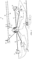
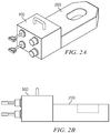
FIGS. 2A and 2B (referred to collectively herein asFIG. 2 ) depict one example of a disclosed subsea drive module connected with a subsea tool. -
FIGS. 3A and 3B (referred to collectively herein asFIG. 3 ) depict example subsea drive module embodiments coupled with a subsea tool. -
FIGS. 4A ,4B, and 4C (referred to collectively herein asFIG. 4 ) depict other example subsea drive module embodiments coupled with a subsea tool. -
FIG. 1 depicts an example subsea production system 10 (commonly referred to in the industry as a drill center) suitable for using various subsea drive module embodiments disclosed herein. Thesystem 10 may include asubsea manifold 20 deployed on thesea floor 15 in proximity to one or more subsea trees 22 (also referred to in the art as Christmas trees). As is known to those of ordinary skill each of thetrees 22 is generally deployed above a corresponding subterranean well (not shown). In the depicted embodiment, fluid communication is provided between each of thetrees 22 and themanifold 20 via aflowline jumper 40. Themanifold 20 may also be in fluid communication with other subsea structures, such as one or more pipe line end terminals (PLETs) 24. Each of the PLETs is intended to provide fluid communication with acorresponding pipeline 28. Fluid communication is commonly provided between thePLETs 24 and themanifold 20 viacorresponding flowline jumpers 40. -
FIG. 1 further depicts a subsea umbilical termination unit (SUTU) 30. The SUTU 30 may be in electrical and/or electronic communication with the surface via anumbilical line 32.Control lines 34 provide electrical and/or hydraulic communication between thevarious subsea structures sea floor 15 and the SUTU 30 (and therefore with the surface via the umbilical line 32). - It will be appreciated that the disclosed embodiments are not limited merely to the subsea production system configuration depicted on
FIG. 1 . As is known to those of ordinary skill in the art, numerous subsea configurations are known in the industry, with individual fields commonly employing custom configurations having substantially any number of interconnected subsea structures. Notwithstanding, remotely operated vehicles (ROVs) and/or autonomous underwater vehicles (AUVs) are commonly employed to service various subsea structures in the production system. A number of deliverable tools, such as seal retrieval and replacement tools and connector hub cleaning tools are commonly employed. - The aforementioned deliverable tools are conventionally powered using hydraulics, which can be problematic. For example, hydraulic connectors can be subject to leakage and therefore may introduce contaminants into the subsea environment. The use of hydraulic power also requires the use of dedicated hydraulic lines extending from the subsea tool to a pressurized hydraulic fluid source such as a SOTU. The hydraulic lines increase the weight and size of the subsea tool and may also become entangled with other subsea equipment during tool delivery (thereby significantly complicating the delivery process, especially in confined spaces).
-
FIGS. 2A and 2B (collectivelyFIG. 2 ) depict one example of a disclosedsubsea drive module 100 connected with asubsea tool 200.FIG. 2A depicts a perspective view of themodule 100 andtool 200 whileFIG. 2B depicts a side view. Thesubsea tool 200 may be configured to service a subsea structure. The subsea structures may include substantially any subsea structure, for example, including a manifold, a tree, a PLET, a SOTU, a pipeline, or a jumper as described above with respect toFIG. 1 . Thesubsea tool 200 may likewise include substantially any suitable subsea tool, for example, a connector seal retrieval and replacement tool, a connector hub cleaning tool, chemical injection valves and assemblies, subsea sampling tools, production flow modules such as chokes and flow meters, intervention tools, torque tools, vibration monitoring tools and sensors, locks, overrides, or substantially any other tool that may be driven (or powered) by a remote electrical drive unit and delivered by a remotely operated vehicle (ROV) or autonomous underwater vehicle (AUV). It will be understood that use of the disclosedsubsea drive module 100 is expressly not limited to any particular subsea structure orsubsea tool 200. - It will be further understood that the disclosed subsea drive module embodiments are intended to function as a "self-contained" unit that provides electrical and/or mechanical power (e.g., via a magnetic coupling or via an electrical connector) to
subsea tool 200. The subsea drive module embodiments may be configured to provide drive power to substantially any vertical or horizontal subsea tools such as vertical or horizontal connector tooling. - With continued reference to
FIG. 2 , thesubsea drive module 100 is configured to provide drive power to thesubsea tool 200. In one example embodiment,subsea drive module 100 may be magnetically coupled with a drive mechanism in thesubsea tool 200 such that no direct mechanical connection is required (as described in more detail below with respect toFIGS. 3 and4 ). In this way thesubsea drive module 100 may further be sealed and pressure balanced internally for use in deep water subsea operations (e.g., to water depths exceeding 10,000 feet). In certain embodiments, thesubsea drive module 100 may include various electronic instrumentation (not depicted) for providing instrumentation and communications support to thesubsea tool 200 and/or other subsea systems (not shown). In another example embodiment, electrical power (e.g., DC battery power) may be provided to the subsea tool via a hardwired electrical connection. -
FIGS. 3A and 3B (referred to collectively herein asFIG. 3 ) depict example subseadrive module embodiments 100 and 100' magnetically coupled with asubsea tool 200. InFIG. 3A subseadrive module embodiment 100 includes an electrical power supply 120 (such as a battery pack) and anelectrical motor 130 deployed in a pressurebalanced housing 110. Theelectrical motor 130 is configured to drive a magnetic coupling 140 (e.g., via drive shaft 135) which in turn may drive a correspondingmagnetic coupling 240 deployed in thesubsea tool 200 via a noncontact magnetic coupling. Rotation of the magnetic coupling 240 (viaelectric motor 130 and magnetic coupling 140) may in turn rotate a rigid shaft or flex drive 250 which in turn powers thetool 200. The depicted subseadrive module embodiment 100 further includes anROV interface 150 having a plurality of switches 152 (such as non-contact magnetic switches) and optical indicators 154 (such as light emitting diodes). The optical indicators may be configured to indicate an operational status of the subsea drive module and/or the subsea tool while the switches may be configured to control the function of the module (e.g. to turn themotor 130 on/off and/or to change the motor rotation rate) such that an ROV may interact with thesubsea drive module 100 and/or thesubsea tool 200. - In
FIG. 3B subsea drive module embodiment 100' is similar toembodiment 100 in that it includes anelectrical power supply 120 such as a lithium battery pack and anelectrical motor 130 deployed in a housing 110'. Theelectrical motor 130 is configured to drive amagnetic coupling 160 via gearingmechanism 145. Thegears 145 may be configured for example to provide increased torque to thecoupling 160. Subsea drive module 100' differs from drive module 100 (FIG. 3A ) in that it includes an external magnetic coupling (external to housing 110') that is intended to contact and magnetically lock to a correspondingmagnetic coupling 260 in the subsea tool 200'. Subsea drive module 100' may further include an ROV interface 150 (e.g., as described above with respect toFIG. 3 ) and an ROV handle 158 that may enable an ROV to transport the module 100'. -
FIGS. 4A-4C (referred to collectively herein asFIG. 4 ) depict example subseadrive module embodiments 300 and 300'. Thedrive module embodiment 300 depicted onFIGS. 4A and4B is similar to embodiment 100 (FIG. 3A ) in that it is substantially horizontal and is configured for magnetic coupling with asubsea tool 200.Subsea drive module 300 includes anelectrical power supply 320 such as a battery pack and first and secondelectrical motors 330 and 330' deployed in a housing 310 (e.g., a pressure balanced housing as described above). In the depicted embodiment,electrical motor 330 is configured to drivemagnetic coupling 340 which is intended to contact and magnetically lock with correspondingmagnetic coupling 270. Electrical motor 330' is configured to drive magnetic coupling 340' which is intended to drive corresponding magnetic coupling 270' via a noncontact magnetic drive. - With continued reference to
FIGS. 4A and4B ,subsea drive module 300 further includes anelectronics module 360 for providing electronic instrumentation and/or communications support to thesubsea tool 200 and/or other subsea systems (not shown). As described above with respect toFIG. 3A ,drive module 300 may further include anROV interface panel 350 having a plurality of switches 352 (such as non-contact magnetic switches) and optical indicators 354 (such as light emitting diodes). Thedrive module 300 may further include one or more ROV handles for transporting themodule 300 in the subsea environment. -
FIG. 4C depicts a substantially vertical subsea drive module embodiment 300' deployed in acorresponding cavity 210 in a subsea tool 200 (such as a subsea tree). Drive module embodiment 300' includes anelectrical power supply 320 that provides power toelectronics module 360. The electrical power supply also provides power toelectrical connectors 370 that are configured to mate with and to provide electrical power to correspondingelectrical connectors 280 insubsea tool 200. In such an embodiment, the subsea drive module may provide electrical power (e.g., DC battery power) to thesubsea tool 200. The electrical connectors may include substantially any suitable electrical connectors suitable for use in subsea environments such as conventional "wetable" connectors or inductive connectors. Such connectors are known in the industry and may provide a reliable connection in high pressure subsea environments. Subsea drive module 300' may further include one or more ROV handles and an ROV interface panel having a plurality of switches and optical indicators (not shown onFIG. 4C ). - It will be understood that the
electronics module 360 depicted onFIG. 4 may include substantially any suitable electronic hardware, firmware, and/or software. For example, the electronics module may include a communications interface configured to provide electronic communication between the subsea drive module and other subsea structures and/or a surface command center. The communications interface may be configured, for example, to provide two-way wireless or hard wired communication with the subsea tool, the surface command center, a subsea structure, and/or an ROV or AUV. - The
electronics module 360 may further include an electronic processor (not shown), such as a microprocessor or a microcontroller, and may also include processor-readable or computer-readable program code embodying logic, including instructions for controlling the function of the subsea drive module as well as the subsea tool. The electronics module may further include other controllable components, such as other sensors, data storage devices, power supplies, timers, and the like. The electronics module may further optionally include volatile or non-volatile memory or a data storage device for downhole storage of various sensor measurements and subsea tool performance metrics. The disclosed embodiments are expressly not limited in these regards. - With continued reference to
FIGS. 3 and4 , it will be understood that the disclosed subsea drive module embodiments may provide both an electrical power source and electronic instrumentation that is able to communicate with other subsea equipment and the surface command center. This may advantageously enable system functions such as docking location and positioning to be remotely monitored and controlled via the switches and optical indicators in the ROV interface. Known wireless and hardwired electronic communication methods may be employed to provide communication between the subsea tool, the subsea drive module, and the surface command center. - With still further reference to
FIGS. 3 and4 , the disclosed subsea drive module embodiments are intended to provide electrical and/or mechanical drive power to a subsea tool. The disclosed subsea drive module embodiments are particularly advantageous when powering a deliverable subsea tool such as a connector seal retrieval and replacement tool, a connector hub cleaning tool, or substantially any other tool that may be delivered by a remotely operated vehicle (ROV) or autonomous underwater vehicle (AUV). It will be further understood that the disclosed subsea drive module embodiments may obviate the need to power such tools using hydraulics. The elimination of hydraulics may advantageously provide for a clean, "zero leak" power source which in turn may significantly reduce environmental impact. - The disclosed subsea drive module embodiments may further enable the development of "all-electric" electrically powered ROV tools such as prime movers, position monitoring instrumentation, and communications and operation logging tools. Such tools may be remotely controlled, monitored, and computerized via the disclosed subsea drive module.
- Although a portable all-electric subsea drive module has been described in detail, it should be understood that various changes, substitutions and alternations can be made herein without departing from the spirit and scope of the disclosure as defined by the appended claims.
Claims (16)
- A subsea tool assembly comprising:a subsea tool; anda subsea drive module connected to and configured to provide drive power to the subsea tool, the subsea drive module including (i) a housing configured for operation in a subsea environment, (ii) an electrical motor deployed in the housing, the electrical motor configured to rotate a magnetic coupling, the magnetic coupling sized and shaped to magnetically engage a corresponding magnetic coupling in the subsea tool, and (iii) an electrical power supply deployed in the housing, the electrical power supply electrically connected and configured to provide electrical power to the motor;wherein said rotation of the magnetic coupling rotates the corresponding magnetic coupling in the subsea tool thereby providing the drive power to the subsea tool.
- The subsea tool assembly of claim 1, wherein the subsea tool is a connector seal retrieval and replacement tool, a connector hub cleaning tool, a chemical injection valve assembly, a subsea sampling tool, a production flow module, a subsea intervention tool, a torque tool, or a vibration monitoring tool.
- The subsea tool assembly of claim 1, wherein the housing is sealed and pressure balanced internally for use in deep water subsea operations.
- The subsea tool assembly of claim 1, wherein the magnetic coupling is deployed in the housing and configured to engage the corresponding magnetic coupling in the subsea tool via a non-contact magnetic coupling.
- The subsea tool assembly of claim 1, wherein the magnetic coupling is deployed external to the housing and configured to engage the corresponding magnetic coupling in the subsea tool via a contact magnetic coupling.
- The subsea tool assembly of claim 1, wherein the electrical power supply comprises a battery.
- The subsea tool assembly of claim 1, wherein the subsea drive module further comprises an electronics module in electronic communication with the subsea tool.
- The subsea tool assembly of claim 1, wherein the subsea drive module further comprises an electronics module configured to be in electronic communication with a surface command center.
- A subsea drive module configured to power a subsea tool, the subsea drive module comprising:a housing configured for operation in a subsea environment;an electrical motor deployed in the housing, the electrical motor configured to rotate a magnetic coupling, the magnetic coupling sized and shaped to magnetically engage a corresponding magnetic coupling in the subsea tool; andan electrical power supply deployed in the housing, the electrical power supply electrically connected to the motor and configured to provide electrical power to the motor.
- The subsea tool assembly of claim 9, wherein the housing is sealed and pressure balanced internally for use in deep water subsea operations.
- The subsea tool assembly of claim 9, wherein:the magnetic coupling is deployed in the housing and configured to engage the corresponding magnetic coupling in the subsea tool via a non-contact magnetic coupling; orthe magnetic coupling is deployed external to the housing and configured to engage the corresponding magnetic coupling in the subsea tool via a contact magnetic coupling.
- The subsea tool assembly of claim 9, wherein the electrical power supply comprises a battery.
- The subsea tool assembly of claim 9, wherein the subsea drive module further comprises an electronics module in electronic communication with the subsea tool and with a surface command center.
- A subsea drive module configured to power a subsea tool, the subsea drive module comprising:a housing configured for operation in a subsea environment;an electronics module deployed in the housing, the electronics module configured to provide electronic communication between the subsea drive module and the subsea tool;an electrical power supply deployed in the housing; andat least one electrical connector deployed external to the housing, the electrical connector electrically connected to the power supply and configured to mate with a corresponding electrical connector on the subsea tool such that electrical power is provided to the subsea tool when the electrical connector is mated with the corresponding electrical connector on the subsea tool.
- The subsea tool assembly of claim 14, wherein the housing is sealed and pressure balanced internally for use in deep water subsea operations.
- The subsea tool assembly of claim 9, wherein the electrical power supply comprises a battery.
Applications Claiming Priority (1)
| Application Number | Priority Date | Filing Date | Title |
|---|---|---|---|
| US15/465,810 US9926770B1 (en) | 2017-03-22 | 2017-03-22 | Portable all-electric subsea drive module |
Publications (3)
| Publication Number | Publication Date |
|---|---|
| EP3401498A2 true EP3401498A2 (en) | 2018-11-14 |
| EP3401498A3 EP3401498A3 (en) | 2019-02-20 |
| EP3401498B1 EP3401498B1 (en) | 2020-12-23 |
Family
ID=61633088
Family Applications (1)
| Application Number | Title | Priority Date | Filing Date |
|---|---|---|---|
| EP18163440.3A Active EP3401498B1 (en) | 2017-03-22 | 2018-03-22 | Portable all-electric subsea drive module |
Country Status (2)
| Country | Link |
|---|---|
| US (1) | US9926770B1 (en) |
| EP (1) | EP3401498B1 (en) |
Families Citing this family (2)
| Publication number | Priority date | Publication date | Assignee | Title |
|---|---|---|---|---|
| MX2020007636A (en) * | 2018-01-18 | 2020-10-12 | Safe Marine Transfer Llc | Subsea smart electric control unit. |
| NO20190107A1 (en) | 2019-01-29 | 2020-07-30 | Icon Instr As | Pressure-equalized wireline apparatus |
Family Cites Families (15)
| Publication number | Priority date | Publication date | Assignee | Title |
|---|---|---|---|---|
| NO312376B1 (en) * | 2000-05-16 | 2002-04-29 | Kongsberg Offshore As | Method and apparatus for controlling valves of an underwater installation |
| US7156169B2 (en) * | 2003-12-17 | 2007-01-02 | Fmc Technologies, Inc. | Electrically operated actuation tool for subsea completion system components |
| US7216714B2 (en) * | 2004-08-20 | 2007-05-15 | Oceaneering International, Inc. | Modular, distributed, ROV retrievable subsea control system, associated deepwater subsea blowout preventer stack configuration, and methods of use |
| AU2007268355A1 (en) * | 2006-05-26 | 2007-12-06 | Oceaneering As | An apparatus for operating controllable installation means |
| NO20075029L (en) * | 2007-10-05 | 2009-04-06 | Multicontrol Hydraulics As | Electrically operated hydraulic pump unit with accumulator module for use in underwater control systems. |
| GB2478077B (en) * | 2008-02-26 | 2012-02-29 | Zetechtics Ltd | Subsea test apparatus, assembly and method |
| NO333503B1 (en) * | 2011-09-08 | 2013-06-24 | Capwell As | Wireline Unit |
| EP2579438A1 (en) * | 2011-10-06 | 2013-04-10 | Siemens Aktiengesellschaft | Power cell for deepwater application |
| EP2845249B1 (en) * | 2012-05-02 | 2019-02-20 | EaglePicher Technologies, LLC | Reserve battery to provide power for subsea applications |
| US9222555B2 (en) * | 2012-08-06 | 2015-12-29 | Cameron International Corporation | Linear actuator |
| NO335707B1 (en) * | 2013-02-06 | 2015-01-26 | Aker Subsea As | Subsea valve |
| US11339788B2 (en) * | 2013-08-15 | 2022-05-24 | Transocean Innovation Labs Ltd | Subsea pumping apparatuses and related methods |
| GB2521626C (en) * | 2013-12-23 | 2019-10-30 | Subsea 7 Ltd | Transmission of power underwater |
| US20150267704A1 (en) * | 2014-03-18 | 2015-09-24 | Fuglesangs Subsea As | Sealed magnetic drive for rotary machine |
| US9964113B2 (en) * | 2015-05-11 | 2018-05-08 | Fuglesangs Subsea As | Omnirise hydromag “variable speed magnetic coupling system for subsea pumps” |
-
2017
- 2017-03-22 US US15/465,810 patent/US9926770B1/en active Active
-
2018
- 2018-03-22 EP EP18163440.3A patent/EP3401498B1/en active Active
Non-Patent Citations (1)
| Title |
|---|
| None |
Also Published As
| Publication number | Publication date |
|---|---|
| US9926770B1 (en) | 2018-03-27 |
| EP3401498B1 (en) | 2020-12-23 |
| EP3401498A3 (en) | 2019-02-20 |
Similar Documents
| Publication | Publication Date | Title |
|---|---|---|
| EP3401498B1 (en) | Portable all-electric subsea drive module | |
| BR112016014083B1 (en) | METHOD, SUBSEA SYSTEM AND SUBSEA POWER UNIT FOR SUPPLYING ELECTRIC ENERGY TO UNDERWATER SUBSEA EQUIPMENT | |
| EP3017144A1 (en) | Subsea system comprising a crawler | |
| AU2011333810B2 (en) | Downhole system having a wireless unit | |
| US20170204704A1 (en) | Remotely-Operated Subsea Control Module | |
| US9732879B2 (en) | Sensor assembly for monitoring a fluid extraction component | |
| US10605038B2 (en) | Latch assembly using on-board miniature hydraulics for RCD applications | |
| US20230111367A1 (en) | Downhole intervention and completion drone and methods of use | |
| WO2011059925A2 (en) | Deploying an electrically-activated tool into a subsea well | |
| US11739605B2 (en) | Electrical drilling and production systems and methods | |
| WO2017044221A1 (en) | System for communicating data via fluid lines | |
| EP3426880A1 (en) | Subsea electric actuator system | |
| WO2017031564A1 (en) | Underwater electric power generator system | |
| EP3296504B1 (en) | Method to communicate between subsea devices | |
| KR101455654B1 (en) | Bilge suction system of thruster canister | |
| US10141682B2 (en) | Subsea electrical connector with removable ROV mating tool | |
| CN218913308U (en) | Emergency intervention device and underwater engineering operation level robot | |
| AU2021335961B2 (en) | Multi valve electrical actuator | |
| CN113757192B (en) | Cable laying robot |
Legal Events
| Date | Code | Title | Description |
|---|---|---|---|
| PUAI | Public reference made under article 153(3) epc to a published international application that has entered the european phase |
Free format text: ORIGINAL CODE: 0009012 |
|
| STAA | Information on the status of an ep patent application or granted ep patent |
Free format text: STATUS: THE APPLICATION HAS BEEN PUBLISHED |
|
| AK | Designated contracting states |
Kind code of ref document: A2 Designated state(s): AL AT BE BG CH CY CZ DE DK EE ES FI FR GB GR HR HU IE IS IT LI LT LU LV MC MK MT NL NO PL PT RO RS SE SI SK SM TR |
|
| AX | Request for extension of the european patent |
Extension state: BA ME |
|
| PUAL | Search report despatched |
Free format text: ORIGINAL CODE: 0009013 |
|
| AK | Designated contracting states |
Kind code of ref document: A3 Designated state(s): AL AT BE BG CH CY CZ DE DK EE ES FI FR GB GR HR HU IE IS IT LI LT LU LV MC MK MT NL NO PL PT RO RS SE SI SK SM TR |
|
| AX | Request for extension of the european patent |
Extension state: BA ME |
|
| RIC1 | Information provided on ipc code assigned before grant |
Ipc: H02K 11/33 20160101ALI20190111BHEP Ipc: F16K 31/04 20060101ALI20190111BHEP Ipc: H02K 7/116 20060101ALI20190111BHEP Ipc: H02K 7/11 20060101ALI20190111BHEP Ipc: E21B 33/035 20060101AFI20190111BHEP Ipc: H02K 5/22 20060101ALI20190111BHEP Ipc: E21B 33/038 20060101ALI20190111BHEP Ipc: E21B 33/037 20060101ALI20190111BHEP Ipc: E21B 41/04 20060101ALI20190111BHEP Ipc: H02K 5/132 20060101ALI20190111BHEP Ipc: E21B 41/00 20060101ALI20190111BHEP |
|
| STAA | Information on the status of an ep patent application or granted ep patent |
Free format text: STATUS: REQUEST FOR EXAMINATION WAS MADE |
|
| 17P | Request for examination filed |
Effective date: 20190820 |
|
| RBV | Designated contracting states (corrected) |
Designated state(s): AL AT BE BG CH CY CZ DE DK EE ES FI FR GB GR HR HU IE IS IT LI LT LU LV MC MK MT NL NO PL PT RO RS SE SI SK SM TR |
|
| GRAP | Despatch of communication of intention to grant a patent |
Free format text: ORIGINAL CODE: EPIDOSNIGR1 |
|
| STAA | Information on the status of an ep patent application or granted ep patent |
Free format text: STATUS: GRANT OF PATENT IS INTENDED |
|
| INTG | Intention to grant announced |
Effective date: 20200721 |
|
| GRAS | Grant fee paid |
Free format text: ORIGINAL CODE: EPIDOSNIGR3 |
|
| GRAA | (expected) grant |
Free format text: ORIGINAL CODE: 0009210 |
|
| STAA | Information on the status of an ep patent application or granted ep patent |
Free format text: STATUS: THE PATENT HAS BEEN GRANTED |
|
| AK | Designated contracting states |
Kind code of ref document: B1 Designated state(s): AL AT BE BG CH CY CZ DE DK EE ES FI FR GB GR HR HU IE IS IT LI LT LU LV MC MK MT NL NO PL PT RO RS SE SI SK SM TR |
|
| REG | Reference to a national code |
Ref country code: GB Ref legal event code: FG4D |
|
| REG | Reference to a national code |
Ref country code: DE Ref legal event code: R096 Ref document number: 602018010972 Country of ref document: DE |
|
| REG | Reference to a national code |
Ref country code: AT Ref legal event code: REF Ref document number: 1347893 Country of ref document: AT Kind code of ref document: T Effective date: 20210115 |
|
| REG | Reference to a national code |
Ref country code: IE Ref legal event code: FG4D |
|
| PG25 | Lapsed in a contracting state [announced via postgrant information from national office to epo] |
Ref country code: GR Free format text: LAPSE BECAUSE OF FAILURE TO SUBMIT A TRANSLATION OF THE DESCRIPTION OR TO PAY THE FEE WITHIN THE PRESCRIBED TIME-LIMIT Effective date: 20210324 Ref country code: RS Free format text: LAPSE BECAUSE OF FAILURE TO SUBMIT A TRANSLATION OF THE DESCRIPTION OR TO PAY THE FEE WITHIN THE PRESCRIBED TIME-LIMIT Effective date: 20201223 Ref country code: FI Free format text: LAPSE BECAUSE OF FAILURE TO SUBMIT A TRANSLATION OF THE DESCRIPTION OR TO PAY THE FEE WITHIN THE PRESCRIBED TIME-LIMIT Effective date: 20201223 |
|
| REG | Reference to a national code |
Ref country code: AT Ref legal event code: MK05 Ref document number: 1347893 Country of ref document: AT Kind code of ref document: T Effective date: 20201223 |
|
| REG | Reference to a national code |
Ref country code: NL Ref legal event code: MP Effective date: 20201223 |
|
| PG25 | Lapsed in a contracting state [announced via postgrant information from national office to epo] |
Ref country code: BG Free format text: LAPSE BECAUSE OF FAILURE TO SUBMIT A TRANSLATION OF THE DESCRIPTION OR TO PAY THE FEE WITHIN THE PRESCRIBED TIME-LIMIT Effective date: 20210323 Ref country code: LV Free format text: LAPSE BECAUSE OF FAILURE TO SUBMIT A TRANSLATION OF THE DESCRIPTION OR TO PAY THE FEE WITHIN THE PRESCRIBED TIME-LIMIT Effective date: 20201223 Ref country code: SE Free format text: LAPSE BECAUSE OF FAILURE TO SUBMIT A TRANSLATION OF THE DESCRIPTION OR TO PAY THE FEE WITHIN THE PRESCRIBED TIME-LIMIT Effective date: 20201223 |
|
| REG | Reference to a national code |
Ref country code: NO Ref legal event code: T2 Effective date: 20201223 |
|
| PG25 | Lapsed in a contracting state [announced via postgrant information from national office to epo] |
Ref country code: NL Free format text: LAPSE BECAUSE OF FAILURE TO SUBMIT A TRANSLATION OF THE DESCRIPTION OR TO PAY THE FEE WITHIN THE PRESCRIBED TIME-LIMIT Effective date: 20201223 Ref country code: HR Free format text: LAPSE BECAUSE OF FAILURE TO SUBMIT A TRANSLATION OF THE DESCRIPTION OR TO PAY THE FEE WITHIN THE PRESCRIBED TIME-LIMIT Effective date: 20201223 |
|
| REG | Reference to a national code |
Ref country code: LT Ref legal event code: MG9D |
|
| PG25 | Lapsed in a contracting state [announced via postgrant information from national office to epo] |
Ref country code: LT Free format text: LAPSE BECAUSE OF FAILURE TO SUBMIT A TRANSLATION OF THE DESCRIPTION OR TO PAY THE FEE WITHIN THE PRESCRIBED TIME-LIMIT Effective date: 20201223 Ref country code: RO Free format text: LAPSE BECAUSE OF FAILURE TO SUBMIT A TRANSLATION OF THE DESCRIPTION OR TO PAY THE FEE WITHIN THE PRESCRIBED TIME-LIMIT Effective date: 20201223 Ref country code: PT Free format text: LAPSE BECAUSE OF FAILURE TO SUBMIT A TRANSLATION OF THE DESCRIPTION OR TO PAY THE FEE WITHIN THE PRESCRIBED TIME-LIMIT Effective date: 20210423 Ref country code: SK Free format text: LAPSE BECAUSE OF FAILURE TO SUBMIT A TRANSLATION OF THE DESCRIPTION OR TO PAY THE FEE WITHIN THE PRESCRIBED TIME-LIMIT Effective date: 20201223 Ref country code: CZ Free format text: LAPSE BECAUSE OF FAILURE TO SUBMIT A TRANSLATION OF THE DESCRIPTION OR TO PAY THE FEE WITHIN THE PRESCRIBED TIME-LIMIT Effective date: 20201223 Ref country code: EE Free format text: LAPSE BECAUSE OF FAILURE TO SUBMIT A TRANSLATION OF THE DESCRIPTION OR TO PAY THE FEE WITHIN THE PRESCRIBED TIME-LIMIT Effective date: 20201223 Ref country code: SM Free format text: LAPSE BECAUSE OF FAILURE TO SUBMIT A TRANSLATION OF THE DESCRIPTION OR TO PAY THE FEE WITHIN THE PRESCRIBED TIME-LIMIT Effective date: 20201223 |
|
| PG25 | Lapsed in a contracting state [announced via postgrant information from national office to epo] |
Ref country code: AT Free format text: LAPSE BECAUSE OF FAILURE TO SUBMIT A TRANSLATION OF THE DESCRIPTION OR TO PAY THE FEE WITHIN THE PRESCRIBED TIME-LIMIT Effective date: 20201223 Ref country code: PL Free format text: LAPSE BECAUSE OF FAILURE TO SUBMIT A TRANSLATION OF THE DESCRIPTION OR TO PAY THE FEE WITHIN THE PRESCRIBED TIME-LIMIT Effective date: 20201223 |
|
| REG | Reference to a national code |
Ref country code: DE Ref legal event code: R097 Ref document number: 602018010972 Country of ref document: DE |
|
| PG25 | Lapsed in a contracting state [announced via postgrant information from national office to epo] |
Ref country code: IS Free format text: LAPSE BECAUSE OF FAILURE TO SUBMIT A TRANSLATION OF THE DESCRIPTION OR TO PAY THE FEE WITHIN THE PRESCRIBED TIME-LIMIT Effective date: 20210423 |
|
| PG25 | Lapsed in a contracting state [announced via postgrant information from national office to epo] |
Ref country code: AL Free format text: LAPSE BECAUSE OF FAILURE TO SUBMIT A TRANSLATION OF THE DESCRIPTION OR TO PAY THE FEE WITHIN THE PRESCRIBED TIME-LIMIT Effective date: 20201223 Ref country code: MC Free format text: LAPSE BECAUSE OF FAILURE TO SUBMIT A TRANSLATION OF THE DESCRIPTION OR TO PAY THE FEE WITHIN THE PRESCRIBED TIME-LIMIT Effective date: 20201223 Ref country code: IT Free format text: LAPSE BECAUSE OF FAILURE TO SUBMIT A TRANSLATION OF THE DESCRIPTION OR TO PAY THE FEE WITHIN THE PRESCRIBED TIME-LIMIT Effective date: 20201223 |
|
| PLBE | No opposition filed within time limit |
Free format text: ORIGINAL CODE: 0009261 |
|
| REG | Reference to a national code |
Ref country code: CH Ref legal event code: PL |
|
| STAA | Information on the status of an ep patent application or granted ep patent |
Free format text: STATUS: NO OPPOSITION FILED WITHIN TIME LIMIT |
|
| PG25 | Lapsed in a contracting state [announced via postgrant information from national office to epo] |
Ref country code: DK Free format text: LAPSE BECAUSE OF FAILURE TO SUBMIT A TRANSLATION OF THE DESCRIPTION OR TO PAY THE FEE WITHIN THE PRESCRIBED TIME-LIMIT Effective date: 20201223 |
|
| 26N | No opposition filed |
Effective date: 20210924 |
|
| REG | Reference to a national code |
Ref country code: BE Ref legal event code: MM Effective date: 20210331 |
|
| PG25 | Lapsed in a contracting state [announced via postgrant information from national office to epo] |
Ref country code: FR Free format text: LAPSE BECAUSE OF NON-PAYMENT OF DUE FEES Effective date: 20210331 Ref country code: ES Free format text: LAPSE BECAUSE OF FAILURE TO SUBMIT A TRANSLATION OF THE DESCRIPTION OR TO PAY THE FEE WITHIN THE PRESCRIBED TIME-LIMIT Effective date: 20201223 Ref country code: CH Free format text: LAPSE BECAUSE OF NON-PAYMENT OF DUE FEES Effective date: 20210331 Ref country code: LI Free format text: LAPSE BECAUSE OF NON-PAYMENT OF DUE FEES Effective date: 20210331 Ref country code: IE Free format text: LAPSE BECAUSE OF NON-PAYMENT OF DUE FEES Effective date: 20210322 Ref country code: LU Free format text: LAPSE BECAUSE OF NON-PAYMENT OF DUE FEES Effective date: 20210322 |
|
| PG25 | Lapsed in a contracting state [announced via postgrant information from national office to epo] |
Ref country code: SI Free format text: LAPSE BECAUSE OF FAILURE TO SUBMIT A TRANSLATION OF THE DESCRIPTION OR TO PAY THE FEE WITHIN THE PRESCRIBED TIME-LIMIT Effective date: 20201223 |
|
| PG25 | Lapsed in a contracting state [announced via postgrant information from national office to epo] |
Ref country code: IS Free format text: LAPSE BECAUSE OF FAILURE TO SUBMIT A TRANSLATION OF THE DESCRIPTION OR TO PAY THE FEE WITHIN THE PRESCRIBED TIME-LIMIT Effective date: 20210423 |
|
| PG25 | Lapsed in a contracting state [announced via postgrant information from national office to epo] |
Ref country code: BE Free format text: LAPSE BECAUSE OF NON-PAYMENT OF DUE FEES Effective date: 20210331 |
|
| PGFP | Annual fee paid to national office [announced via postgrant information from national office to epo] |
Ref country code: NO Payment date: 20230309 Year of fee payment: 6 |
|
| PG25 | Lapsed in a contracting state [announced via postgrant information from national office to epo] |
Ref country code: CY Free format text: LAPSE BECAUSE OF FAILURE TO SUBMIT A TRANSLATION OF THE DESCRIPTION OR TO PAY THE FEE WITHIN THE PRESCRIBED TIME-LIMIT Effective date: 20201223 |
|
| PG25 | Lapsed in a contracting state [announced via postgrant information from national office to epo] |
Ref country code: HU Free format text: LAPSE BECAUSE OF FAILURE TO SUBMIT A TRANSLATION OF THE DESCRIPTION OR TO PAY THE FEE WITHIN THE PRESCRIBED TIME-LIMIT; INVALID AB INITIO Effective date: 20180322 |
|
| P01 | Opt-out of the competence of the unified patent court (upc) registered |
Effective date: 20231212 |
|
| PG25 | Lapsed in a contracting state [announced via postgrant information from national office to epo] |
Ref country code: MK Free format text: LAPSE BECAUSE OF FAILURE TO SUBMIT A TRANSLATION OF THE DESCRIPTION OR TO PAY THE FEE WITHIN THE PRESCRIBED TIME-LIMIT Effective date: 20201223 |
|
| PGFP | Annual fee paid to national office [announced via postgrant information from national office to epo] |
Ref country code: DE Payment date: 20231229 Year of fee payment: 7 Ref country code: GB Payment date: 20240108 Year of fee payment: 7 |