EP3401119A1 - Vehicle for containing loads - Google Patents
Vehicle for containing loads Download PDFInfo
- Publication number
- EP3401119A1 EP3401119A1 EP18171038.5A EP18171038A EP3401119A1 EP 3401119 A1 EP3401119 A1 EP 3401119A1 EP 18171038 A EP18171038 A EP 18171038A EP 3401119 A1 EP3401119 A1 EP 3401119A1
- Authority
- EP
- European Patent Office
- Prior art keywords
- rolling elements
- vehicle
- leg
- supporting rolling
- frame
- Prior art date
- Legal status (The legal status is an assumption and is not a legal conclusion. Google has not performed a legal analysis and makes no representation as to the accuracy of the status listed.)
- Granted
Links
- 238000005096 rolling process Methods 0.000 claims abstract description 142
- 230000005484 gravity Effects 0.000 claims description 9
- 230000004913 activation Effects 0.000 claims description 3
- 239000000725 suspension Substances 0.000 description 6
- 235000004443 Ricinus communis Nutrition 0.000 description 2
- 230000005540 biological transmission Effects 0.000 description 2
- 238000004804 winding Methods 0.000 description 2
- 241001136792 Alle Species 0.000 description 1
- 240000000528 Ricinus communis Species 0.000 description 1
- 229910000831 Steel Inorganic materials 0.000 description 1
- 230000001133 acceleration Effects 0.000 description 1
- 230000006978 adaptation Effects 0.000 description 1
- 238000010009 beating Methods 0.000 description 1
- 230000001419 dependent effect Effects 0.000 description 1
- 238000005516 engineering process Methods 0.000 description 1
- 239000012530 fluid Substances 0.000 description 1
- 238000011089 mechanical engineering Methods 0.000 description 1
- 239000002184 metal Substances 0.000 description 1
- 239000007787 solid Substances 0.000 description 1
- 230000003068 static effect Effects 0.000 description 1
- 239000010959 steel Substances 0.000 description 1
Images


Classifications
-
- B—PERFORMING OPERATIONS; TRANSPORTING
- B60—VEHICLES IN GENERAL
- B60B—VEHICLE WHEELS; CASTORS; AXLES FOR WHEELS OR CASTORS; INCREASING WHEEL ADHESION
- B60B19/00—Wheels not otherwise provided for or having characteristics specified in one of the subgroups of this group
- B60B19/14—Ball-type wheels
-
- B—PERFORMING OPERATIONS; TRANSPORTING
- B60—VEHICLES IN GENERAL
- B60B—VEHICLE WHEELS; CASTORS; AXLES FOR WHEELS OR CASTORS; INCREASING WHEEL ADHESION
- B60B19/00—Wheels not otherwise provided for or having characteristics specified in one of the subgroups of this group
- B60B19/003—Multidirectional wheels
-
- B—PERFORMING OPERATIONS; TRANSPORTING
- B60—VEHICLES IN GENERAL
- B60B—VEHICLE WHEELS; CASTORS; AXLES FOR WHEELS OR CASTORS; INCREASING WHEEL ADHESION
- B60B33/00—Castors in general; Anti-clogging castors
- B60B33/04—Castors in general; Anti-clogging castors adjustable, e.g. in height; linearly shifting castors
- B60B33/06—Castors in general; Anti-clogging castors adjustable, e.g. in height; linearly shifting castors mounted retractably
-
- B—PERFORMING OPERATIONS; TRANSPORTING
- B62—LAND VEHICLES FOR TRAVELLING OTHERWISE THAN ON RAILS
- B62B—HAND-PROPELLED VEHICLES, e.g. HAND CARTS OR PERAMBULATORS; SLEDGES
- B62B3/00—Hand carts having more than one axis carrying transport wheels; Steering devices therefor; Equipment therefor
- B62B3/04—Hand carts having more than one axis carrying transport wheels; Steering devices therefor; Equipment therefor involving means for grappling or securing in place objects to be carried; Loading or unloading equipment
- B62B3/06—Hand carts having more than one axis carrying transport wheels; Steering devices therefor; Equipment therefor involving means for grappling or securing in place objects to be carried; Loading or unloading equipment for simply clearing the load from the ground
- B62B3/0612—Hand carts having more than one axis carrying transport wheels; Steering devices therefor; Equipment therefor involving means for grappling or securing in place objects to be carried; Loading or unloading equipment for simply clearing the load from the ground power operated
-
- B—PERFORMING OPERATIONS; TRANSPORTING
- B62—LAND VEHICLES FOR TRAVELLING OTHERWISE THAN ON RAILS
- B62D—MOTOR VEHICLES; TRAILERS
- B62D37/00—Stabilising vehicle bodies without controlling suspension arrangements
-
- B—PERFORMING OPERATIONS; TRANSPORTING
- B62—LAND VEHICLES FOR TRAVELLING OTHERWISE THAN ON RAILS
- B62D—MOTOR VEHICLES; TRAILERS
- B62D61/00—Motor vehicles or trailers, characterised by the arrangement or number of wheels, not otherwise provided for, e.g. four wheels in diamond pattern
- B62D61/02—Motor vehicles or trailers, characterised by the arrangement or number of wheels, not otherwise provided for, e.g. four wheels in diamond pattern with two road wheels in tandem on the longitudinal centre line of the vehicle
- B62D61/04—Motor vehicles or trailers, characterised by the arrangement or number of wheels, not otherwise provided for, e.g. four wheels in diamond pattern with two road wheels in tandem on the longitudinal centre line of the vehicle with two other wheels which are coaxial
-
- B—PERFORMING OPERATIONS; TRANSPORTING
- B62—LAND VEHICLES FOR TRAVELLING OTHERWISE THAN ON RAILS
- B62D—MOTOR VEHICLES; TRAILERS
- B62D61/00—Motor vehicles or trailers, characterised by the arrangement or number of wheels, not otherwise provided for, e.g. four wheels in diamond pattern
- B62D61/10—Motor vehicles or trailers, characterised by the arrangement or number of wheels, not otherwise provided for, e.g. four wheels in diamond pattern with more than four wheels
Definitions
- the invention is in the field of mechanical engineering and can be used advantageously in particular in the field of vehicle technology. It can be used, for example, in logistics in driverless transport systems, but also generally in vehicles used for transporting goods, with particular advantages when it comes to steerable and maneuverable vehicles in a small space.
- Vehicles with four or more wheels often have high stability, but in principle the support situation is statically overdetermined, which is usually compensated by the suspension of wheels or rollers. However, this results in a simultaneous distribution of weight on the wheels, so that either all wheels must be driven and braked or for the transmission of braking and driving forces, if this happens only over part of the wheels, no optimal traction, d. H. no maximum weight load of the drive / brake wheels can be achieved.
- the present invention is based on the background of the prior art, the task of optimizing a vehicle for receiving loads with respect to the number and arrangement of the rolling elements.
- the invention relates to a vehicle for receiving loads with at least one load receiving device, which is supported on a frame, with at least one drive motor and at least four frame-carrying rolling elements in the form of at least two supporting rolling elements and two supporting rolling elements, wherein two of the supporting rolling elements are arranged side by side in the direction of travel of the vehicle, of which at least one, in particular two, are drivable by a drive motor and wherein in the straight-ahead direction, which corresponds to the longitudinal direction of the vehicle, in front of and behind the supporting rolling elements in each case at least a support roller element is arranged.
- a solution of the problem is achieved in that at least one connecting leg is pivotally attached to the frame at least one pivot bearing, on which a rotation bearing device with a mounted therein Supporting rolling element is attached, and that the load receiving device is supported on the one hand on the connecting leg between the pivot bearing and the rotation bearing device and on the other hand on the / the connecting leg (s) opposite side of the supporting rolling elements, wherein the connecting leg is formed as a connecting leg of a trapezoidal rocker, connecting a first leg and a second leg, wherein the trapezoidal rocker is secured to the first leg on the frame, wherein at least one rotation bearing means of one of the support rolling elements is fixed to a second leg of the trapezoidal rocker, which is opposite to the first leg, and wherein the Load receiving device on which the first and the second leg hingedly connecting connecting leg is supported in particular between the first and the second leg.
- the pivot bearing has a horizontal pivot axis, so that the connecting leg is pivotable in a vertical plane perpendicular to the road surface on which the vehicle is movable. It can also be provided a plurality of individually pivotally mounted connecting leg, on each of which support rolling elements are rotatably mounted.
- the connecting legs can each also be part of a trapezoidal arrangement, as will be explained in more detail below.
- the load-receiving device is in each case movably supported on the connecting legs in a further pivot bearing in order to take into account the mobility of the connecting leg (s) relative to the frame.
- a connecting line between the rotary bearings is defined, so that, starting from this connecting line, two sides on this side and beyond the connecting line, d. H. on both sides of the carrying rolling elements, are defined.
- connecting leg (s) and the supporting rolling elements connected thereto are located on a first side of this connecting line, which may be identical to a common axis of rotation of the supporting rolling elements, then lie on the second side of the connecting line, which is opposite the first side, one or more further supporting rolling elements whose Rotary bearing devices are rigidly connected to the frame.
- the center of gravity of the loaded or unloaded load-receiving device is advantageously above the connecting line, and one or more supporting elements of the load-receiving device are supported on the frame on the side of the connecting line opposite the connecting leg (s).
- the / the connecting leg (s) may be formed as rods, rods or straight or curved metal strips.
- first leg and the second leg are arranged in the direction of travel of the vehicle at a distance one behind the other, which is smaller than twice the diameter of the support member mounted on the second leg, in particular smaller than its simple diameter.
- the first and second legs may be disposed parallel to each other and vertical to a road surface on which the vehicle is moving.
- the vehicle may be, for example, a self-navigating and / or automatically controlled and / or driverless vehicle. This has a navigation device and / or a guide device for guiding the vehicle to prepared lanes.
- the supporting rolling elements are arranged side by side, and at least one of them is drivable, so that the two supporting rolling elements define at least one drive axle.
- a brake may be provided which acts on at least one of the supporting rolling elements, in particular on both supporting rolling elements.
- the connecting line between the two supporting rolling elements is advantageously provided below the center of gravity of the load-receiving device, wherein in determining the center of gravity, a uniform loading is required.
- a common axis of rotation of the supporting rolling elements can be arranged directly below the center of gravity of the uniformly loaded load-receiving device or below the center of gravity of the vehicle.
- At least one support roller element is provided both in front of and behind the connecting line between the supporting rolling elements.
- one or more wheels are sprung to provide ground contact of all wheels under various static and dynamic load conditions, and also on uneven road surfaces.
- the problem that arises is that on the one hand a sufficiently long travel of the rolling elements must be ensured so that a permanent ground contact can be guaranteed, and on the other hand, the stiffness of the suspension should be designed so that no pitching or vibration of the vehicle during the ride occur.
- one of the supporting rolling elements is fastened to the frame of the vehicle by means of a trapezoidal rocker.
- a trapezoidal rocker This results in that even with a change in load a straight or at least with respect to the angle of inclination unchanged position of the supporting rolling element and its fastening device is maintained.
- a beating / rotation of the roller is avoided in a load change.
- This also allows a movement of the supporting rolling element in the vertical direction, without the load receiving device follows this movement in full, that is, the load bearing device moves only minimally with a suitable choice of leverage.
- An advantageous embodiment of the invention is that the center of gravity of the vehicle in the rest position on a horizontal surface in the longitudinal direction of the vehicle on the trapezoidal rocker or the / the connecting leg (s) opposite side of the supporting rolling elements.
- the support roller element which is attached to the trapezoidal rocker, thus carries only a very small part of the vehicle weight, except for dynamic exceptions, regardless of whether this is loaded or not.
- the majority of the weight lies on the axle / common axle or the axles of the supporting rolling elements, which also serve for the drive and the transmission of the braking deceleration.
- the load-receiving device and the frame and the connecting leg or all articulated parts of the vehicle can be connected together without a spring element.
- the forces between these parts are then determined solely by the laws of leverage and dynamics.
- the chassis of the vehicle can thus be completely unsprung.
- the trapezoidal rocker is sprung in that between at least two of the legs of the trapezoidal rocker, a spring element is arranged.
- the points on the trapezoidal rocker, d. H. on at least two different legs of the trapezoidal rocker, to which the spring element is attached, can be selected such that the lever ratios and the strength and spring constant of the spring are designed to spring the vehicle along a sufficient spring travel.
- a resilient connecting element between a connecting leg and the frame of the vehicle may be provided.
- a further advantageous embodiment of the invention can provide that the load-receiving device is supported on the connecting leg between the first and the second leg of the trapezoidal rocker at a region which is closer to the first leg than the second leg or the pivot bearing closer than the rotation bearing device of the / supported on the connecting leg supporting rolling elements.
- the supporting rolling elements are advantageously designed as wheels, in particular as solid rubber wheels or as air-filled or filled with a fluid other than air wheels. However, they can in principle also be designed as mounted ball elements.
- each of the supporting rolling elements can be driven by means of a respective drive motor.
- the vehicle can be steered by a suitable coordinated control of the drive motors.
- By detecting the rotation angle of the supporting rolling elements both the distance traveled by the vehicle and its orientation can be determined or determined.
- the vehicle can be rotated immediately in place about a vertical axis, with a minimum space for such a rotational movement of the vehicle is taken.
- a particularly advantageous arrangement is given by a central arrangement of the supporting rolling elements in the longitudinal direction of the vehicle.
- the acceleration and deceleration of the vehicle is achieved by simultaneous drive of both drive motors in an optimal manner.
- the weight distribution between the supporting rolling elements and a supporting rolling element may be such that at least two thirds of the vehicle weight rest on the supporting rolling elements, while at most one third of the vehicle weight rests on a supporting rolling element.
- the supporting rolling elements can be particularly light, for example as ball-rollers or omnidirectional rollers, which have advantages over steering-block castors.
- a common control device for coordinated activation of the at least two drive motors of the supporting rolling elements for steering the vehicle.
- the control may, as mentioned above, be odometric, i. H. by determining the rotational angle of the driven wheels / supporting rolling elements.
- the drive motors are designed as rotary encoders, for example in the form of electric stepper motors. Thus, the rotation angle of the drive wheels can be detected directly on the motors.
- a further advantageous embodiment of the invention can provide that drive motors are designed as brushless electric motors.
- Such electric motors have a high efficiency with high torque. They are also very flexible controllable, in particular by the control in the form of pulse width modulated signals.
- each of the supporting rolling elements and / or each of the drive motors has a sensor device for detecting a rotation angle.
- the rotational angles of the supporting rolling elements are detected by separate sensors, for example Hall sensors.
- Rotation angles can also be realized on the drive motor by a sensor in the form of a device for measuring the electromagnetic reaction of the stator winding of the motor.
- a further advantageous embodiment of the invention can provide that the supporting rolling elements are designed as wheels or rotatably mounted balls.
- the design of the supporting rolling elements as mounted balls before the embodiment as steerable rollers has the advantage that in the directional change of the vehicle steerable rollers each require the pivoting of the support wheel, which on the one hand generates resistance to movement and on the other hand increases the minimum turning radius of the vehicle in many cases becomes.
- the use of steerable wheels in the form of wheels is also advantageous because of their high mechanical strength in many cases.
- a further advantageous embodiment provides a vehicle with two arranged in the direction of travel in front of the supporting rolling elements supporting rolling elements and two in the direction of travel behind the supporting rolling elements supporting rolling elements, at least two, in particular all four supporting rolling elements on each one pivotally
- the connecting leg mounted on the frame are mounted and wherein the load-receiving direction is respectively supported on the connecting legs.
- a drivable adjusting device is provided, which allows the lifting of the load receiving device relative to the / supporting roll element (s).
- the chassis is yielding and follows the bumps.
- the load-bearing device maintains its height regardless of the load. Uneven floors can be compensated by the described passive elements.
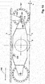
- FIG. 1 shows a vehicle 1 with a load receiving device 2 in the form of a box which is supported on a frame 3. Of two supporting rolling elements 4, 5, which carry the frame 3, is in FIG. 1 one shown. Moreover, in FIG. 1 a support roller element 6 is shown.
- FIG. 2 is in the bottom view of the frame 3, which may for example consist of a steel sheet, completely recognizable.
- the two supporting rolling elements 4, 5 are shown, each of which is connected to a drive motor 8, 9.
- the carrying rolling elements 4, 5 are designed as wheels in the form of tires and mounted coaxially with each other, so that they jointly define a drive axle.
- the support roller element 6 is fixedly attached to the frame 3 in the form of a wheel.
- the support roller element 6 lies on a first side of the support roller elements 4, 5, while on the opposite side at the opposite end of the support roller element 6 of the frame 3, a further support roller element 7, also in the form of a wheel, is arranged ,
- the support roller element 7 is not struck directly on the frame 3, but connected to this by means of a trapezoidal rocker.
- the supporting and supporting rolling elements 4, 5, 6, 7 are arranged diamond-shaped (at the corners of a rhombus) when viewed from the underside of the vehicle.
- FIG. 3 is a side view of the vehicle is shown, in which both the load-receiving device 2 and the frame 3, the support roller elements 6, 7 and one of the supporting rolling elements 5 can be seen.
- FIG. 4 shows a view of the vehicle from the bottom, wherein the frame 3, the support rollers 6, 7 and the support rollers 4, 5 are shown.
- FIG. 5 is the vehicle in a longitudinal section along the line AA the FIG. 4 represented, whereby the suspension of the supporting rolling element 7 is visible on the frame 3 in the form of a trapezoidal rocker.
- the trapezoidal swingarm is in FIG. 6 shown enlarged.
- FIG. 6 shows that a first leg 10 of the trapezoidal rocker is fixed to the frame 3 in the region of an end face of the vehicle.
- the opposite second leg 11 of the trapezoidal rocker is fixedly connected to the wheel 7, which forms a supporting rolling element of the vehicle.
- an upper, first connecting leg 12 and a lower, second connecting leg 13 are provided on the trapezoidal rocker, wherein each of the connecting legs 12, 13 connects two ends of the legs 10, 11 to each other in an articulated manner. This results in that the second leg 11 exclusively in the direction of arrow 14, ie perpendicular to the road surface, is displaceable.
- the first and second legs and the connecting legs form a parallelogram, wherein the connecting legs, each measured between the joints, may be shorter than the triple, double or single length of the first and second leg. It can also be provided that the connecting leg or the first connecting leg is shorter than twice or simply the diameter of the supporting rolling element, whose bearing is attached to the connecting leg or to the parallelogram.
- the supporting rolling element 7 is displaceable in the vertical direction and can thus be pressed against the road surface, so that the vehicle with all four rolling elements touches the road surface. In this case, the entire chassis of the vehicle can be unsprung and free of spring elements, since the leverage of the various legs ensure a pressure of all roles in the ground.
- the load-receiving device is seen in the direction of travel before and behind the connecting line between the supporting rolling elements each supported in a pivot joint so that the support can adapt to load changes.
- At least one of the support points, in particular the pivot joint, which is arranged directly on the frame, may be horizontally displaceable for adaptation to a loading situation.
- FIG. 7 a vehicle according to the invention is shown in a slightly modified embodiment, wherein FIG. 7 in the view with FIG. 1 is comparable.
- the difference of the vehicles of FIGS. 1 and 7 is that the vehicle according to FIG. 7 at its front end a support roller element 6 ' in the form of a rotatably mounted ball, whereby the vehicle on the support roller member 6 'in each direction is rollable.
- both support rolling elements 6 ', 7' are formed at the two front ends of the vehicle as ball elements.
- FIG. 9 the support roller elements 6 ', 7' are seen in a side view, and in FIG. 10 in a view of the underside of the vehicle.
- FIG. 11 shows that the support roller element 7 'as well as the support roller element 7 of the first vehicle version by means of a trapezoidal rocker is attached to the frame 3.
- FIG. 12 shows in enlarged form the connection of the supporting rolling element 7 'with the frame, wherein the trapezoidal rocker is covered by a panel.
- the suspension of the supporting rolling element 7 'on the frame is designed as well as the suspension of the supporting rolling element 7 to the frame 3 according to the FIG. 6 ,
- the inventive design of the vehicle makes it possible to store the largest possible proportion of the total weight of the vehicle on the supporting rolling elements 4, 5, while a small proportion of the weight on the support roller element 6, 6 'can store.
- the further supporting rolling element 7, 7 'can be designed and arranged such that in the rest position it absorbs practically no portion of the weight of the vehicle and / or the load and is pressed against the roadway surface only by means of the trapezoidal rocker.
- FIG. 13 shows a representation in which the leverage ratios of the mutually movable parts are made clear schematically.
- the vehicle in the FIGS. 13 and 14 is shown, has two supporting rolling elements 4, 5 in the form of individually driven wheels, whose bearings are connected by an imaginary connecting line 108.
- the center of gravity of the vehicle is ideally above the connecting line 108.
- Connecting line 108 are two supporting rolling elements 6 ", 6 '" in the form of wheels whose rotary bearings are fixedly connected to the frame 3.
- the connecting legs 112, 113 are articulated in a respective pivot bearing 100 to the frame and pivotable in a vertical plane. At the connecting legs 112, 113, the rotation bearing devices 101 of the wheels 107, 107 'are fixed. Along the connecting legs 112, 113 101 supporting elements 105 are supported between the pivot bearings 100 and the rotation bearing devices, which are connected to the load receiving device 2. On the support elements 105 opposite side of the connecting line 108 further, connected to the load-receiving device supporting elements 104 are supported directly on the frame 3.
- Each of the rollers 6 ", 6 '", 107, 107' can be replaced by another support roller element, for example a ball rotatable in a rotation bearing device, wherein the attachment or articulation of the support roller elements to the frame 3 remains unchanged.
- FIG. 14 are the support points at which the load-bearing device 2 is supported by means of the support members 104, 105 on the frame 3, indicated by the arrows 110, 111, 115, 116.
- FIG. 15 a vehicle is shown with a frame 3 and a load-bearing device 2 in the form of a loading surface 2, which is supported on the pivot joint 120 on the frame and by means of the support member 105 on the connecting leg 112.
- the connecting leg is pivotally mounted on the pivot joint 100.
- the wheel 107 is rotatably mounted on the connecting leg 112.
- the support member 105 is movably supported on the connecting leg 112 in the middle between the bearing of the wheel 107 and the pivot joint 100.
- the compensated by the pivotable wheel 107 height difference in the road surface 106 is designated by "x".
- FIG. 16 shows a vehicle with a load receiving device 2, which is supported on a frame 3.
- the supporting rolling elements 4, 5 are designed as wheels with a common drive axle, but separate drive motors.
- the front in the direction of travel 109 supporting rolling elements are mounted as rotatably mounted roller balls 121, 122 directly to the frame 3.
- the supporting rolling elements 123, 124 are mounted as rolling balls on the connecting lever 112 '. This is articulated in the pivot joint 100 'on the frame 3.
- the support member 105' is supported, which carries the load bearing 2.
- the support member 105 'and the connecting lever 112' are bow-shaped semicircular formed as bent sheets, and all articulation and support points are provided for each of the support rollers 123, 124 double.
- FIG. 17 shows a vehicle in which a lifting device is provided for lifting the load receiving device.
- the lifting of the load-receiving device takes place by pivoting the arm on which the support roller element is arranged, in the sense of the double arrow.
- FIG. 18 shows a raised position of the load receiving device after the arm on which the support roller member is mounted, has been pivoted to the axis of the support rollers. This can be z. B. by a traction drive, such as the winding of a pull rope, done.
Landscapes
- Engineering & Computer Science (AREA)
- Mechanical Engineering (AREA)
- Chemical & Material Sciences (AREA)
- Combustion & Propulsion (AREA)
- Transportation (AREA)
- Vehicle Body Suspensions (AREA)
Abstract
Die Erfindung bezieht sich auf ein Fahrzeug zur Aufnahme von Lasten mit wenigstens einer Lastaufnahmeeinrichtung (2), die auf einem Rahmen (3) abgestützt ist, mit wenigstens einem Antriebsmotor (8, 9) und mit wenigstens vier den Rahmen tragenden Rollelementen (4, 5, 6, 6', 7, 7') in Form von wenigstens zwei Trag-Rollelementen (4, 5) und zwei Stütz-Rollelementen (6, 6', 7, 7'), wobei zwei der Trag-Rollelemente in Fahrtrichtung des Fahrzeugs nebeneinander angeordnet sind, von denen wenigstens eines, insbesondere zwei, durch einen Antriebsmotor (8, 9) antreibbar sind und wobei in Geradeaus-Fahrtrichtung, die der Längsrichtung des Fahrzeugs entspricht, vor und hinter den Trag-Rollelementen (4, 5) jeweils wenigstens ein Stütz-Rollelement (6, 6', 7, 7') angeordnet ist.The invention relates to a vehicle for receiving loads with at least one load receiving device (2) which is supported on a frame (3) with at least one drive motor (8, 9) and at least four rolling elements (4, 5) carrying the frame , 6, 6 ', 7, 7') in the form of at least two supporting rolling elements (4, 5) and two supporting rolling elements (6, 6 ', 7, 7'), wherein two of the supporting rolling elements in the direction of travel of the Vehicle are arranged side by side, of which at least one, in particular two, by a drive motor (8, 9) are driven and wherein in the straight-ahead direction corresponding to the longitudinal direction of the vehicle, in front of and behind the supporting rolling elements (4, 5) respectively at least one support roller element (6, 6 ', 7, 7') is arranged.
Dadurch, dass an dem Rahmen (3) an wenigstens einem Schwenklager (100) schwenkbar wenigstens ein Verbindungsschenkel (12, 13, 112, 113) befestigt ist, an dem eine Rotationslagereinrichtung (101) mit einem darin gelagerten Stütz-Rollelement (7, 7', 107) befestigt ist, und dass die Lastaufnahmeeinrichtung einerseits an dem Verbindungsschenkel (12, 13, 112) zwischen dem Schwenklager (100) und der Rotationslagereinrichtung (101) abgestützt ist und andererseits auf der dem/den Verbindungsschenkel(n) (12, 13, 112, 113) gegenüberliegenden Seite der Trag-Rollelemente (4, 5), wird Bewegung des Stütz-Rollelements mittels der Trapezschwinge derart möglich, dass ein langer vertikaler Weg des Stütz-Rollelements zu einer minimalen Auslenkung der Lastaufnahmeeinrichtung führt. Damit ergibt sich ein optimiertes Stützverhalten des Fahrzeugs.

Description
Die Erfindung liegt auf dem Gebiet des Maschinenbaus und ist insbesondere im Bereich der Fahrzeugtechnik mit Vorteil einsetzbar. Sie kann beispielsweise in der Logistik bei führerlosen Transportsystemen eingesetzt werden, jedoch auch generell bei Fahrzeugen, die dem Lastentransport dienen, wobei sich besondere Vorteile ergeben, wenn es sich um lenkbare und auf kleinem Raum manövrierbare Fahrzeuge handelt.The invention is in the field of mechanical engineering and can be used advantageously in particular in the field of vehicle technology. It can be used, for example, in logistics in driverless transport systems, but also generally in vehicles used for transporting goods, with particular advantages when it comes to steerable and maneuverable vehicles in a small space.
Aus dem Stand der Technik und der menschlichen Erfahrung ist bekannt, dass einachsige Fahrzeuge besonders gut lenkbar und auf kleinem Raum manövrierfähig sind. Sollen solche Fahrzeuge autark, d. h. nicht als Anhänger, sondern als selbständiges Fahrzeug eingesetzt werden, so sind so viele Stütz-Rollelemente vorzusehen, dass das Fahrzeug einen stabilen Stand, d. h. eine ausreichend große Standfläche, erhält.From the state of the art and the human experience it is known that single-axle vehicles are particularly easy to steer and manoeuvrable in a small space. If such vehicles are self-sufficient, ie not used as trailers, but as an independent vehicle, so many support rolling elements are provided that the vehicle a stable state, ie, a sufficiently large footprint receives.
Es sind weiterhin dreirädrige Fahrzeuge bekannt, die eine gute Manövrierfähigkeit aufweisen, jedoch insbesondere bei Kurvenfahrten eine suboptimale Stabilität haben.There are still known three-wheeled vehicles, which have good maneuverability, but in particular have a sub-optimal stability when cornering.
Fahrzeuge mit vier und mehr Rädern weisen oft eine hohe Stabilität auf, jedoch ist grundsätzlich die Stützsituation statisch überbestimmt, was üblicherweise durch die Federung von Rädern oder Rollen ausgeglichen wird. Hierdurch ergibt sich jedoch gleichzeitig eine Verteilung des Gewichts auf die Räder, so dass entweder alle Räder angetrieben und gebremst werden müssen oder für die Übertragung der Brems- und Antriebskräfte, wenn dies nur über einen Teil der Räder geschieht, keine optimale Bodenhaftung, d. h. keine maximale Gewichtsbelastung der Antriebs-/Bremsräder erzielt werden kann.Vehicles with four or more wheels often have high stability, but in principle the support situation is statically overdetermined, which is usually compensated by the suspension of wheels or rollers. However, this results in a simultaneous distribution of weight on the wheels, so that either all wheels must be driven and braked or for the transmission of braking and driving forces, if this happens only over part of the wheels, no optimal traction, d. H. no maximum weight load of the drive / brake wheels can be achieved.
Der vorliegenden Erfindung liegt vor dem Hintergrund des Standes der Technik die Aufgabe zugrunde, ein Fahrzeug zur Aufnahme von Lasten bezüglich der Zahl und Anordnung der Rollelemente zu optimieren.The present invention is based on the background of the prior art, the task of optimizing a vehicle for receiving loads with respect to the number and arrangement of the rolling elements.
Die Aufgabe wird mit den Merkmalen der Erfindung durch ein Fahrzeug gemäß Patentanspruch 1 gelöst. Die abhängigen Patentansprüche 2 bis 11 betreffen vorteilhafte Ausgestaltungen.The object is achieved with the features of the invention by a vehicle according to
Demgemäß bezieht sich die Erfindung auf ein Fahrzeug zur Aufnahme von Lasten mit wenigstens einer Lastaufnahmeeinrichtung, die auf einem Rahmen abgestützt ist, mit wenigstens einem Antriebsmotor und mit wenigstens vier den Rahmen tragenden Rollelementen in Form von wenigstens zwei Trag-Rollelementen und zwei Stütz-Rollelementen, wobei zwei der Trag-Rollelemente in Fahrtrichtung des Fahrzeugs nebeneinander angeordnet sind, von denen wenigstens eines, insbesondere zwei, durch einen Antriebsmotor antreibbar sind und wobei in Geradeaus-Fahrtrichtung, die der Längsrichtung des Fahrzeugs entspricht, vor und hinter den Trag-Rollelementen jeweils wenigstens ein Stütz-Rollelement angeordnet ist.Accordingly, the invention relates to a vehicle for receiving loads with at least one load receiving device, which is supported on a frame, with at least one drive motor and at least four frame-carrying rolling elements in the form of at least two supporting rolling elements and two supporting rolling elements, wherein two of the supporting rolling elements are arranged side by side in the direction of travel of the vehicle, of which at least one, in particular two, are drivable by a drive motor and wherein in the straight-ahead direction, which corresponds to the longitudinal direction of the vehicle, in front of and behind the supporting rolling elements in each case at least a support roller element is arranged.
Eine Lösung der Aufgabe gelingt dadurch, dass an dem Rahmen an wenigstens einem Schwenklager schwenkbar wenigstens ein Verbindungsschenkel befestigt ist, an dem eine Rotationslagereinrichtung mit einem darin gelagerten Stütz-Rollelement befestigt ist, und dass die Lastaufnahmeeinrichtung einerseits an dem Verbindungsschenkel zwischen dem Schwenklager und der Rotationslagereinrichtung abgestützt ist und andererseits auf der dem/den Verbindungsschenkel(n) gegenüberliegenden Seite der Trag-Rollelemente, wobei der Verbindungsschenkel als Verbindungsschenkel einer Trapezschwinge ausgebildet ist, der einen ersten Schenkel und einen zweiten Schenkel verbindet, wobei die Trapezschwinge mit dem ersten Schenkel an dem Rahmen befestigt ist, wobei wenigstens eine Rotationslagereinrichtung eines der Stütz-Rollelemente an einem zweiten Schenkel der Trapezschwinge befestigt ist, der dem ersten Schenkel gegenüberliegt, und wobei die Lastaufnahmeeinrichtung an dem den ersten und den zweiten Schenkel gelenkig verbindenden Verbindungsschenkel insbesondere zwischen dem ersten und dem zweiten Schenkel abgestützt ist.A solution of the problem is achieved in that at least one connecting leg is pivotally attached to the frame at least one pivot bearing, on which a rotation bearing device with a mounted therein Supporting rolling element is attached, and that the load receiving device is supported on the one hand on the connecting leg between the pivot bearing and the rotation bearing device and on the other hand on the / the connecting leg (s) opposite side of the supporting rolling elements, wherein the connecting leg is formed as a connecting leg of a trapezoidal rocker, connecting a first leg and a second leg, wherein the trapezoidal rocker is secured to the first leg on the frame, wherein at least one rotation bearing means of one of the support rolling elements is fixed to a second leg of the trapezoidal rocker, which is opposite to the first leg, and wherein the Load receiving device on which the first and the second leg hingedly connecting connecting leg is supported in particular between the first and the second leg.
Das Schwenklager weist eine horizontale Schwenkachse auf, so dass der Verbindungsschenkel in einer vertikalen Ebene senkrecht zu der Fahrbahnebene schwenkbar ist, auf der das Fahrzeug fahrbar ist. Es können auch mehrere einzeln schwenkbar gelagerte Verbindungsschenkel vorgesehen sein, an denen jeweils Stütz-Rollelemente drehbar gelagert sind. Die Verbindungsschenkel können jeweils auch Teil einer Trapezanordnung sein, wie weiter unten noch näher erläutert wird.The pivot bearing has a horizontal pivot axis, so that the connecting leg is pivotable in a vertical plane perpendicular to the road surface on which the vehicle is movable. It can also be provided a plurality of individually pivotally mounted connecting leg, on each of which support rolling elements are rotatably mounted. The connecting legs can each also be part of a trapezoidal arrangement, as will be explained in more detail below.
Die Lastaufnahmeeinrichtung ist jeweils an den Verbindungsschenkeln in einem weiteren Schwenklager beweglich abgestützt, um der Beweglichkeit des/der Verbindungsschenkel gegenüber dem Rahmen Rechnung zu tragen.The load-receiving device is in each case movably supported on the connecting legs in a further pivot bearing in order to take into account the mobility of the connecting leg (s) relative to the frame.
Durch die Rotationslager der Trag-Rollelemente ist eine Verbindungslinie zwischen den Rotationslagern definiert, so dass, ausgehend von dieser Verbindungslinie, zwei Seiten diesseits und jenseits der Verbindungslinie, d. h. diesseits und jenseits der Trag-Rollelemente, definiert sind.Due to the rotary bearings of the supporting rolling elements, a connecting line between the rotary bearings is defined, so that, starting from this connecting line, two sides on this side and beyond the connecting line, d. H. on both sides of the carrying rolling elements, are defined.
Liegt/liegen der/die Verbindungsschenkel und die mit diesen verbundenen Stütz-Rollelemente auf einer ersten Seite dieser Verbindungslinie, die mit einer gemeinsamen Rotationsachse der Trag-Rollelemente identisch sein kann, so liegen auf der zweiten Seite der Verbindungslinie, die der ersten Seite gegenüberliegt, ein oder mehrere weitere Stütz-Rollelemente, deren Rotationslagereinrichtungen mit dem Rahmen starr verbunden sind. Der Schwerpunkt der beladenen oder unbeladenen Lastaufnahmeeinrichtung liegt vorteilhaft über der Verbindungslinie, und eine oder mehrere Abstützelemente der Lastaufnahmeeinrichtung sind auf dem Rahmen auf der dem/den Verbindungsschenkel(n) gegenüberliegenden Seite der Verbindungslinie abgestützt.If the connecting leg (s) and the supporting rolling elements connected thereto are located on a first side of this connecting line, which may be identical to a common axis of rotation of the supporting rolling elements, then lie on the second side of the connecting line, which is opposite the first side, one or more further supporting rolling elements whose Rotary bearing devices are rigidly connected to the frame. The center of gravity of the loaded or unloaded load-receiving device is advantageously above the connecting line, and one or more supporting elements of the load-receiving device are supported on the frame on the side of the connecting line opposite the connecting leg (s).
Der/die Verbindungsschenkel können als Stangen, Stäbe oder gerade oder gebogene Blechstreifen ausgebildet sein.The / the connecting leg (s) may be formed as rods, rods or straight or curved metal strips.
Zudem kann vorgesehen sein, dass der erste Schenkel und der zweite Schenkel in Fahrtrichtung des Fahrzeugs in einem Abstand hintereinander angeordnet sind, der kleiner als der zweifache Durchmesser des an dem zweiten Schenkel gelagerten Stütz-Rollelements, insbesondere kleiner als dessen einfacher Durchmesser ist.In addition, it can be provided that the first leg and the second leg are arranged in the direction of travel of the vehicle at a distance one behind the other, which is smaller than twice the diameter of the support member mounted on the second leg, in particular smaller than its simple diameter.
Der erste und der zweite Schenkel können parallel zueinander und vertikal zu einer Fahrbahnoberfläche angeordnet sein, auf der sich das Fahrzeug bewegt. Das Fahrzeug kann beispielsweise ein selbstnavigierendes und/oder automatisch gesteuertes und/oder führerloses Fahrzeug sein. Dieses weist eine Navigationseinrichtung und/oder eine Führungseinrichtung zur Leitung des Fahrzeugs an vorbereiteten Fahrspuren auf.The first and second legs may be disposed parallel to each other and vertical to a road surface on which the vehicle is moving. The vehicle may be, for example, a self-navigating and / or automatically controlled and / or driverless vehicle. This has a navigation device and / or a guide device for guiding the vehicle to prepared lanes.
Die Trag-Rollelemente sind nebeneinander angeordnet, und wenigstens eines von ihnen ist antreibbar, so dass die beiden Trag-Rollelemente wenigstens eine Antriebsachse definieren. Zudem kann auch eine Bremse vorgesehen sein, die auf wenigstens eines der Trag-Rollelemente, insbesondere auf beide Trag-Rollelemente, wirkt.The supporting rolling elements are arranged side by side, and at least one of them is drivable, so that the two supporting rolling elements define at least one drive axle. In addition, a brake may be provided which acts on at least one of the supporting rolling elements, in particular on both supporting rolling elements.
Die Verbindungslinie zwischen den beiden Trag-Rollelementen ist vorteilhaft unterhalb des Schwerpunkts der Lastaufnahmeeinrichtung vorgesehen, wobei bei der Ermittlung des Schwerpunkts eine gleichmäßige Beladung vorausgesetzt ist. Vorteilhaft kann eine gemeinsame Drehachse der Trag-Rollelemente unmittelbar unterhalb des Schwerpunkts der gleichmäßig beladenen Lastaufnahmeeinrichtung oder unterhalb des Schwerpunkts des Fahrzeugs angeordnet sein. Wenn die Last im Wesentlichen über den Trag-Rollelementen vorgesehen ist, ergibt sich bei deren Antrieb ein minimaler Schlupf. Hierdurch wird die Steuerung mittels eines Differenzialantriebs genauer und zuverlässiger.The connecting line between the two supporting rolling elements is advantageously provided below the center of gravity of the load-receiving device, wherein in determining the center of gravity, a uniform loading is required. Advantageously, a common axis of rotation of the supporting rolling elements can be arranged directly below the center of gravity of the uniformly loaded load-receiving device or below the center of gravity of the vehicle. When the load is substantially above the supporting rolling elements is provided, resulting in their drive a minimum slip. This makes the control by means of a differential drive more accurate and reliable.
Um ein ausreichendes Maß an Stand- und Fahrsicherheit zu schaffen und auch für dynamische Belastungen eine sinnvolle Stützung des Fahrzeugs zu erreichen, ist üblicherweise in Fahrtrichtung sowohl vor als auch hinter der Verbindungslinie zwischen den Trag-Rollelementen jeweils wenigstens ein Stütz-Rollelement vorgesehen. Üblicherweise werden bei solchen Fahrzeugen mit wenigstens vier Rädern ein oder mehrere Räder gefedert, um einen Bodenkontakt aller Räder bei verschiedenen statischen und dynamischen Belastungszuständen und auch bei unebenen Fahrbahnoberflächen zu garantieren. Das Problem, das sich dabei stellt, ist, dass einerseits ein ausreichend langer Federweg der Rollelemente gewährleistet werden muss, damit ein dauernder Bodenkontakt garantiert werden kann, und dass andererseits die Steifheit der Federung derart gestaltet sein soll, dass keine Nickbewegungen oder Schwingungen des Fahrzeugs während der Fahrt auftreten.In order to create a sufficient degree of stability and driving safety and to achieve a meaningful support of the vehicle for dynamic loads, usually at least one support roller element is provided both in front of and behind the connecting line between the supporting rolling elements. Typically, in such vehicles having at least four wheels, one or more wheels are sprung to provide ground contact of all wheels under various static and dynamic load conditions, and also on uneven road surfaces. The problem that arises is that on the one hand a sufficiently long travel of the rolling elements must be ensured so that a permanent ground contact can be guaranteed, and on the other hand, the stiffness of the suspension should be designed so that no pitching or vibration of the vehicle during the ride occur.
Üblicherweise ist die Funktionstüchtigkeit eines derartigen Fahrzeugs, wenn einzelne Rollelemente gefedert sind, vom Verhältnis der Nutzlast zum Fahrzeugeigengewicht abhängig. Je höher das anteilige zulässige Zuladegewicht ist, desto schwieriger wird es, die Federung so zu gestalten, dass sie sowohl das leere als auch das belastete Fahrzeug in einem sinnvollen Bereich federt. Oft werden deshalb Fahrzeuge zur Aufnahme von Lasten absichtlich schwer ausgeführt oder mit einem Ballastgewicht ausgestattet, um das Leergewicht zu erhöhen.Usually, the functionality of such a vehicle when individual rolling elements are sprung, the ratio of the payload to the vehicle's own weight depends. The higher the proportional permissible load weight, the more difficult it is to design the suspension so that it springs both the empty and the loaded vehicle in a meaningful area. Often, therefore, vehicles for carrying loads are deliberately made heavy or ballasted to increase curb weight.
Gemäß der beschriebenen Ausführungsform ist eines der Stütz-Rollelemente mittels einer Trapezschwinge an dem Rahmen des Fahrzeugs befestigt. Hierdurch ergibt sich, dass auch bei einer Belastungsänderung eine gerade oder zumindest bezüglich des Neigungswinkels unveränderte Position des Stütz-Rollelements und seiner Befestigungsvorrichtung beibehalten wird. Dadurch wird beispielsweise bei Verwendung einer Lenkbockrolle ein Einschlagen / eine Drehung der Rolle bei einer Laständerung vermieden. Dies lässt zudem eine Bewegung des Stütz-Rollelements in vertikaler Richtung zu, ohne dass die Lastaufnahmeeinrichtung dieser Bewegung in vollem Umfang folgt, das heißt, die Lastaufnahmeeinrichtung bewegt sich bei geeigneter Wahl der Hebelverhältnisse nur minimal.According to the described embodiment, one of the supporting rolling elements is fastened to the frame of the vehicle by means of a trapezoidal rocker. This results in that even with a change in load a straight or at least with respect to the angle of inclination unchanged position of the supporting rolling element and its fastening device is maintained. As a result, for example, when using a steering castor a beating / rotation of the roller is avoided in a load change. This also allows a movement of the supporting rolling element in the vertical direction, without the load receiving device follows this movement in full, that is, the load bearing device moves only minimally with a suitable choice of leverage.
Eine vorteilhafte Ausgestaltung der Erfindung liegt darin, dass der Schwerpunkt des Fahrzeugs in Ruhelage auf horizontaler Unterlage in Längsrichtung des Fahrzeugs auf der der Trapezschwinge oder dem/den Verbindungsschenkel(n) gegenüberliegenden Seite der Trag-Rollelemente liegt. Das Stütz-Rollelement, das an der Trapezschwinge befestigt ist, trägt somit bis auf dynamische Ausnahmefälle nur einen sehr geringen Teil des Fahrzeuggewichts, unabhängig davon, ob dieses beladen ist oder nicht. Der Großteil des Gewichts liegt auf der Achse / gemeinsamen Achse oder den Achsen der Trag-Rollelemente, die auch dem Antrieb und der Übertragung der Bremsverzögerung dienen.An advantageous embodiment of the invention is that the center of gravity of the vehicle in the rest position on a horizontal surface in the longitudinal direction of the vehicle on the trapezoidal rocker or the / the connecting leg (s) opposite side of the supporting rolling elements. The support roller element, which is attached to the trapezoidal rocker, thus carries only a very small part of the vehicle weight, except for dynamic exceptions, regardless of whether this is loaded or not. The majority of the weight lies on the axle / common axle or the axles of the supporting rolling elements, which also serve for the drive and the transmission of the braking deceleration.
Zudem kann vorgesehen sein, dass der Rahmen und der Verbindungsschenkel frei von Federelementen miteinander verbunden sind.In addition, it can be provided that the frame and the connecting leg are connected to each other free of spring elements.
Auch die Lastaufnahmeeinrichtung und der Rahmen sowie der Verbindungsschenkel oder alle gelenkig miteinander verbundenen Teile des Fahrzeugs können federelementfrei miteinander verbunden sein. Die Kräfte zwischen diesen Teilen sind dann ausschließlich durch die Hebelgesetze und die Dynamik bestimmt. Das Fahrgestell des Fahrzeugs kann somit auch vollständig ungefedert sein.Also, the load-receiving device and the frame and the connecting leg or all articulated parts of the vehicle can be connected together without a spring element. The forces between these parts are then determined solely by the laws of leverage and dynamics. The chassis of the vehicle can thus be completely unsprung.
Vorteilhaft wird die Trapezschwinge dadurch gefedert, dass zwischen wenigstens zwei der Schenkel der Trapezschwinge ein Federelement angeordnet ist. Die Punkte an der Trapezschwinge, d. h. an wenigstens zwei verschiedenen Schenkeln der Trapezschwinge, an denen das Federelement befestigt wird, können derart ausgewählt werden, dass die Hebelverhältnisse und die Stärke und Federkonstante der Feder geeignet zur Federung des Fahrzeugs entlang eines ausreichenden Federwegs gestaltet sind.Advantageously, the trapezoidal rocker is sprung in that between at least two of the legs of the trapezoidal rocker, a spring element is arranged. The points on the trapezoidal rocker, d. H. on at least two different legs of the trapezoidal rocker, to which the spring element is attached, can be selected such that the lever ratios and the strength and spring constant of the spring are designed to spring the vehicle along a sufficient spring travel.
Allgemein kann ein federndes Verbindungselement zwischen einem Verbindungsschenkel und dem Rahmen des Fahrzeugs vorgesehen sein.In general, a resilient connecting element between a connecting leg and the frame of the vehicle may be provided.
Eine weitere vorteilhafte Ausführungsform der Erfindung kann vorsehen, dass die Lastaufnahmeeinrichtung an dem Verbindungsschenkel zwischen dem ersten und dem zweiten Schenkel der Trapezschwinge an einem Bereich abgestützt ist, der dem ersten Schenkel näher liegt als dem zweiten Schenkel oder dem Schwenklager näher als der Rotationslagereinrichtung des/der an dem Verbindungsschenkel gelagerten Stütz-Rollelemente. Durch diese Gestaltung führt ein langer Federweg des gefederten Stütz-Rollelements nur zu einer geringen Auslenkung des Rahmens bzw. der aufgenommenen Last.A further advantageous embodiment of the invention can provide that the load-receiving device is supported on the connecting leg between the first and the second leg of the trapezoidal rocker at a region which is closer to the first leg than the second leg or the pivot bearing closer than the rotation bearing device of the / supported on the connecting leg supporting rolling elements. By virtue of this design, a long spring travel of the sprung supporting rolling element only leads to a slight deflection of the frame or of the load taken up.
Die Trag-Rollelemente sind vorteilhaft als Räder ausgebildet, insbesondere als Vollgummiräder oder als luftgefüllte oder mit einem anderen Fluid als Luft gefüllte Räder. Sie können jedoch grundsätzlich auch als gelagerte Kugelelemente ausgebildet sein.The supporting rolling elements are advantageously designed as wheels, in particular as solid rubber wheels or as air-filled or filled with a fluid other than air wheels. However, they can in principle also be designed as mounted ball elements.
Vorteilhaft kann zudem vorgesehen sein, dass jedes der Trag-Rollelemente mittels je eines Antriebsmotors antreibbar ist. Mit einem derartigen unabhängigen Antriebsmotor für jedes der Trag-Rollelemente kann das Fahrzeug durch eine geeignete abgestimmte Steuerung der Antriebsmotoren gelenkt werden. Durch eine Erfassung der Drehwinkel der Trag-Rollelemente kann sowohl der zurückgelegte Weg des Fahrzeugs als auch seine Ausrichtung bestimmt oder ermittelt werden. Beispielsweise lässt sich durch einen derartigen Antrieb das Fahrzeug unmittelbar auf der Stelle um eine vertikale Achse drehen, wobei ein minimaler Raum für eine solche Drehbewegung des Fahrzeugs eingenommen wird. Eine besonders vorteilhafte Anordnung ist dabei durch eine mittige Anordnung der Trag-Rollelemente in Längsrichtung des Fahrzeugs gegeben. Die Beschleunigung und das Abbremsen des Fahrzeugs gelingt durch gleichzeitigen Antrieb beider Antriebsmotoren in optimaler Weise. Die Gewichtsverteilung zwischen den Trag-Rollelementen und einem Stütz-Rollelement kann beispielsweise derart gestaltet sein, dass wenigstens zwei Drittel des Fahrzeuggewichts auf den Trag-Rollelementen ruhen, während höchstens ein Drittel des Fahrzeuggewichts auf einem Stütz-Rollelement ruht.Advantageously, it can also be provided that each of the supporting rolling elements can be driven by means of a respective drive motor. With such an independent drive motor for each of the support rollers, the vehicle can be steered by a suitable coordinated control of the drive motors. By detecting the rotation angle of the supporting rolling elements, both the distance traveled by the vehicle and its orientation can be determined or determined. For example, by such a drive, the vehicle can be rotated immediately in place about a vertical axis, with a minimum space for such a rotational movement of the vehicle is taken. A particularly advantageous arrangement is given by a central arrangement of the supporting rolling elements in the longitudinal direction of the vehicle. The acceleration and deceleration of the vehicle is achieved by simultaneous drive of both drive motors in an optimal manner. For example, the weight distribution between the supporting rolling elements and a supporting rolling element may be such that at least two thirds of the vehicle weight rest on the supporting rolling elements, while at most one third of the vehicle weight rests on a supporting rolling element.
Durch geeignete Wahl der Hebelverhältnisse kann der Andruck der Roll-Stützelemente maximiert und der Andruck der Stütz-Rollelemente minimiert werden. Hierdurch können die Stütz-Rollelemente besonders leicht, beispielsweise als Kugelrollen oder omnidirektionale Rollen, ausgeführt werden, die Vorteile vor Lenkbockrollen haben.By suitable choice of the lever ratios of the pressure of the roll support elements can be maximized and the pressure of the support rolling elements are minimized. As a result, the supporting rolling elements can be particularly light, for example as ball-rollers or omnidirectional rollers, which have advantages over steering-block castors.
Zur Lenkung und Navigation des Fahrzeugs kann vorteilhaft eine gemeinsame Steuereinrichtung zur abgestimmten Ansteuerung der wenigstens zwei Antriebsmotoren der Trag-Rollelemente zur Lenkung des Fahrzeugs vorgesehen sein.For steering and navigation of the vehicle can advantageously be provided a common control device for coordinated activation of the at least two drive motors of the supporting rolling elements for steering the vehicle.
Die Steuerung kann, wie oben erwähnt, odometrisch erfolgen, d. h. durch Ermitteln der Drehwinkel der angetriebenen Räder/Trag-Rollelemente. Die Antriebsmotoren sind als Drehgeber ausgebildet, beispielsweise in Form von elektrischen Schrittmotoren. Damit kann der Drehwinkel der Antriebsräder unmittelbar an den Motoren erfasst werden.The control may, as mentioned above, be odometric, i. H. by determining the rotational angle of the driven wheels / supporting rolling elements. The drive motors are designed as rotary encoders, for example in the form of electric stepper motors. Thus, the rotation angle of the drive wheels can be detected directly on the motors.
Eine weitere vorteilhafte Ausgestaltung der Erfindung kann vorsehen, dass Antriebsmotoren als bürstenlose Elektromotoren ausgebildet sind. Solche Elektromotoren weisen eine hohe Effizienz bei gleichzeitig großem Drehmoment auf. Sie sind zudem sehr flexibel steuerbar, insbesondere durch die Ansteuerung in Form von pulsweitenmodulierten Signalen.A further advantageous embodiment of the invention can provide that drive motors are designed as brushless electric motors. Such electric motors have a high efficiency with high torque. They are also very flexible controllable, in particular by the control in the form of pulse width modulated signals.
Es kann auch vorteilhaft vorgesehen sein, dass jedes der Trag-Rollelemente und/oder jeder der Antriebsmotoren eine Sensoreinrichtung zur Erfassung eines Drehwinkels aufweist. In diesem Fall werden die Drehwinkel der Trag-Rollelemente durch gesonderte Sensoren, beispielsweise Hall-Sensoren, erfasst. Drehwinkel können auch am Antriebsmotor durch einen Sensor in Form einer Einrichtung zur Messung der elektromagnetischen Rückwirkung der Statorwicklung des Motors realisiert sein.It can also be advantageously provided that each of the supporting rolling elements and / or each of the drive motors has a sensor device for detecting a rotation angle. In this case, the rotational angles of the supporting rolling elements are detected by separate sensors, for example Hall sensors. Rotation angles can also be realized on the drive motor by a sensor in the form of a device for measuring the electromagnetic reaction of the stator winding of the motor.
Eine weitere vorteilhafte Ausgestaltung der Erfindung kann vorsehen, dass die Stütz-Rollelemente als Räder oder drehbar gelagerte Kugeln ausgebildet sind. Die Ausbildung der Stütz-Rollelemente als gelagerte Kugeln hat vor der Ausgestaltung als lenkbare Rollen den Vorteil, dass bei der Richtungsänderung des Fahrzeugs lenkbare Rollen jeweils das Schwenken des Stützrades erfordern, wodurch einerseits ein Bewegungswiderstand erzeugt und andererseits in vielen Fällen der minimale Wenderadius des Fahrzeugs vergrößert wird. Der Einsatz von lenkbaren Rollen in Form von Rädern ist jedoch wegen deren hoher mechanischer Belastbarkeit in vielen Fällen ebenfalls vorteilhaft.A further advantageous embodiment of the invention can provide that the supporting rolling elements are designed as wheels or rotatably mounted balls. The design of the supporting rolling elements as mounted balls before the embodiment as steerable rollers has the advantage that in the directional change of the vehicle steerable rollers each require the pivoting of the support wheel, which on the one hand generates resistance to movement and on the other hand increases the minimum turning radius of the vehicle in many cases becomes. The use of steerable wheels in the form of wheels, however, is also advantageous because of their high mechanical strength in many cases.
Als weitere vorteilhafte Ausgestaltung der Erfindung kann vorgesehen sein, dass in Längsrichtung des Fahrzeugs auf der der oder den Trapezschwinge(n) oder dem/den Verbindungsschenkel(n) gegenüberliegenden Seite der Trag-Rollelemente ausschließlich Stütz-Rollelemente vorgesehen sind, deren Rotationslager an dem Rahmen unbeweglich befestigt sind. Grundsätzlich ist jedoch nicht ausgeschlossen, dass an einem Fahrzeug auch mehrere mittels einer Trapezschwinge in der oben beschriebenen Art bewegliche Stütz-Rollelemente vorgesehen sind.As a further advantageous embodiment of the invention can be provided that in the longitudinal direction of the vehicle on the or the trapezoidal rocker (s) or the / the connecting leg (s) opposite side of the supporting rolling elements are provided exclusively supporting rolling elements whose rotation bearing on the frame are fixed immovably. In principle, however, it is not excluded that a plurality of movable support rolling elements are also provided on a vehicle by means of a trapezoidal rocker in the manner described above.
Eine weitere vorteilhafte Ausgestaltung sieht ein Fahrzeug mit zwei in Fahrtrichtung vor den Trag-Rollelementen angeordneten Stütz-Rollelementen und zwei in Fahrtrichtung hinter den Trag-Rollelementen angeordneten Stütz-Rollelementen vor, wobei wenigstens zwei, insbesondere alle vier Stütz-Rollelemente an jeweils einem schwenkbar an dem Rahmen gelagerten Verbindungsschenkel gelagert sind und wobei die Lastaufnahmerichtung jeweils an den Verbindungsschenkeln abgestützt ist.A further advantageous embodiment provides a vehicle with two arranged in the direction of travel in front of the supporting rolling elements supporting rolling elements and two in the direction of travel behind the supporting rolling elements supporting rolling elements, at least two, in particular all four supporting rolling elements on each one pivotally The connecting leg mounted on the frame are mounted and wherein the load-receiving direction is respectively supported on the connecting legs.
In einer weiteren Ausführungsform kann bei einem Fahrzeug vorgesehen sein, dass zwischen wenigstens einer der Stütz-Rollelemente und der Lastaufnahmeeinrichtung eine antreibbare Verstelleinrichtung vorgesehen ist, die das Anheben der Lastaufnahmeeinrichtung gegenüber dem/den Stütz-Rollelement(en) ermöglicht.In a further embodiment, it may be provided in a vehicle that between at least one of the supporting rolling elements and the load receiving device, a drivable adjusting device is provided, which allows the lifting of the load receiving device relative to the / supporting roll element (s).
Durch die dargestellten Ausführungsformen kann im Übrigen erreicht werden, dass der Anteil der Traglast auf den einzelnen Rädern unabhängig von der Traglast gleich bleibt. Alle Räder behalten zudem ständig Bodenkontakt, so dass ein stabiler Stand gewährleistet ist.By the embodiments shown can be achieved, moreover, that the proportion of the load on the individual wheels remains the same regardless of the load. All wheels also keep constant ground contact, so that a stable state is guaranteed.
Das Fahrwerk ist nachgiebig und folgt den Bodenunebenheiten. Die Lastaufnahmeeinrichtung behält dabei ihre Höhe unabhängig von der Traglast bei. Bodenunebenheiten könne durch die beschriebenen passiven Elemente ausgeglichen werden.The chassis is yielding and follows the bumps. The load-bearing device maintains its height regardless of the load. Uneven floors can be compensated by the described passive elements.
Im Folgenden wird die Erfindung anhand von Figuren einer Zeichnung gezeigt und nachfolgend erläutert. Dabei zeigt
- Fig. 1
- eine perspektivische Ansicht eines ersten Fahrzeugs schräg von oben,
- Fig. 2
- eine perspektivische Ansicht des Fahrzeugs aus
Figur 1 schräg von unten, - Fig. 3
- eine Seitenansicht eines ersten Fahrzeugs,
- Fig. 4
- eine Ansicht von unten auf ein erstes Fahrzeug,
- Fig. 5
- eine Schnittdarstellung durch ein erstes Fahrzeug,
- Fig. 6
- ein vergrößertes Detail aus der Schnittdarstellung der
Figur 5 , - Fig. 7
- eine perspektivische Ansicht eines zweiten Fahrzeugs von oben,
- Fig. 8
- eine perspektivische Ansicht des Fahrzeugs aus
Figur 7 schräg von unten, - Fig. 9
- eine Seitenansicht des Fahrzeugs aus
Figur 7 , - Fig. 10
- eine Ansicht des Fahrzeugs aus
Figur 7 von unten, - Fig. 11
- eine Schnittansicht des Fahrzeugs aus
Figur 7 , - Fig. 12
- eine Detailansicht aus der Schnittansicht der
Figur 11 , - Fig. 13
- eine Seitenansicht eines weiteren Fahrzeugs, bei dem die Hebelverhältnisse deutlich sichtbar gemacht sind,
- Fig. 14
- eine Ansicht der Unterseite eines Fahrzeugs aus
Figur 13 , in der vier Stütz-Rollelemente erkennbar sind, - Fig. 15
- eine Seitenansicht eines weiteren Fahrzeugs mit Rädern,
- Fig. 16
- eine Ansicht eines Fahrzeugs mit Rollkugeln als Stütz-Roll-elementen perspektivisch von unten,
- Fig. 17
- ein Fahrzeug in einer Seitenansicht mit einer Hebeeinrichtung zum Anheben der Lastaufnahmeeinrichtung sowie
- Fig. 18
- das Fahrzeug aus
Figur 17 in einer angehobenen Position der Lastaufnahmeeinrichtung.
- Fig. 1
- a perspective view of a first vehicle obliquely from above,
- Fig. 2
- a perspective view of the vehicle
FIG. 1 diagonally from below, - Fig. 3
- a side view of a first vehicle,
- Fig. 4
- a view from below of a first vehicle,
- Fig. 5
- a sectional view through a first vehicle,
- Fig. 6
- an enlarged detail of the sectional view of
FIG. 5 . - Fig. 7
- a perspective view of a second vehicle from above,
- Fig. 8
- a perspective view of the vehicle
FIG. 7 diagonally from below, - Fig. 9
- a side view of the vehicle
FIG. 7 . - Fig. 10
- a view of the vehicle
FIG. 7 from underneath, - Fig. 11
- a sectional view of the vehicle
FIG. 7 . - Fig. 12
- a detailed view of the sectional view of
FIG. 11 . - Fig. 13
- a side view of another vehicle, in which the leverage ratios are clearly visible,
- Fig. 14
- a view of the bottom of a vehicle
FIG. 13 in which four supporting rolling elements are recognizable, - Fig. 15
- a side view of another vehicle with wheels,
- Fig. 16
- a view of a vehicle with rolling balls as support rolling elements in perspective from below,
- Fig. 17
- a vehicle in a side view with a lifting device for lifting the load receiving device and
- Fig. 18
- the vehicle off
FIG. 17 in a raised position of the load receiving device.
In
Das Stütz-Rollelement 6 liegt auf einer ersten Seite der Trag-Rollelemente 4, 5, während auf der gegenüberliegenden Seite an dem dem Stütz-Rollelement 6 gegenüberliegenden Ende des Rahmens 3 ein weiteres Stütz-Rollelement 7, ebenfalls in Form eines Rades, angeordnet ist. Das Stütz-Rollelement 7 ist an den Rahmen 3 nicht direkt angeschlagen, sondern mit diesem mittels einer Trapezschwinge verbunden. Auf diese wird weiter unten noch näher eingegangen.The
Die Stütz- und Trag-Rollelemente 4, 5, 6, 7 sind von der Unterseite des Fahrzeugs gesehen rautenförmig (an den Ecken einer Raute) angeordnet.The supporting and supporting
In
In
Die
Aus den
In
Aus
In
Die erfindungsgemäße Ausgestaltung des Fahrzeugs erlaubt es, einen möglichst großen Anteil des Gesamtgewichts des Fahrzeugs auf den Trag-Rollelementen 4, 5 zu lagern, während ein geringer Anteil des Gewichts auf dem Stütz-Rollelement 6, 6' lagern kann. Das weitere Stütz-Rollelement 7, 7' kann derart gestaltet und angeordnet sein, dass es in der Ruheposition praktisch keinen Anteil des Gewichts des Fahrzeugs und/oder der Last aufnimmt und lediglich mittels der Trapezschwinge an die Fahrbahnoberfläche gedrückt ist. Beim Auftreten dynamischer Lasten, beispielsweise beim Beschleunigen, nimmt das Stütz-Rollelement 7, 7' jedoch eine Teillast des Fahrzeugs auf.The inventive design of the vehicle makes it possible to store the largest possible proportion of the total weight of the vehicle on the supporting
Die Verbindungsschenkel 112, 113 sind in je einem Schwenklager 100 an den Rahmen angelenkt und in einer vertikalen Ebene schwenkbar. An den Verbindungsschenkeln 112, 113 sind die Rotationslagereinrichtungen 101 der Räder 107, 107' befestigt. Entlang der Verbindungsschenkel 112, 113 sind zwischen den Schwenklagern 100 und den Rotationslagereinrichtungen 101 Stützelemente 105 abgestützt, die mit der Lastaufnahmeeinrichtung 2 verbunden sind. Auf der den Stützelementen 105 gegenüberliegenden Seite der Verbindungslinie 108 sind weitere, mit der Lastaufnahmeeinrichtung verbundene Stützelemente 104 direkt an dem Rahmen 3 abgestützt.The connecting
Jede der Rollen 6", 6'", 107, 107' kann durch ein anderes Stütz-Rollelement, beispielsweise eine in einer Rotationslagereinrichtung drehbare Kugel, ersetzt werden, wobei die Befestigung oder Anlenkung der Stütz-Rollelemente an dem Rahmen 3 unverändert bleibt.Each of the
In
In
Der durch das schwenkbare Rad 107 ausgeglichene Höhenunterschied in der Fahrbahnoberfläche 106 ist mit "x" bezeichnet.The compensated by the
Die folgenden Aspekte können jeweils für sich oder in Verbindung miteinander eigene Erfindungen darstellen oder mit den Merkmalen der Ansprüche kombiniert werden:
- 1. Aspekt: Fahrzeug zur Aufnahme von Lasten mit wenigstens einer Lastaufnahmeeinrichtung 2, die auf einem Rahmen 3 abgestützt ist, mit wenigstens einem Antriebsmotor 8, 9 und mit wenigstens vier den
Rahmen tragenden Rollelementen Rollelementen Rollelementen Rollelementen Rollelement
dadurch gekennzeichnet, dass
andem Rahmen 3 an wenigstens einem Schwenklager 100 schwenkbar wenigstensein Verbindungsschenkel dem eine Rotationslagereinrichtung 101 mit einem darin gelagerten Stütz-Rollelement
und dass die Lastaufnahmeeinrichtung einerseits andem Verbindungsschenkel dem Schwenklager 100 und derRotationslagereinrichtung 101 abgestützt ist und andererseits auf der dem/den Verbindungsschenkeln Rollelemente - 2. Aspekt:
Fahrzeug nach Aspekt 1, dadurch gekennzeichnet, dass eine Trapezschwinge 10, 11, 12, 13 vorgesehen und mit einem erstenSchenkel 10 andem Rahmen 3 befestigt ist, dass wenigstens eine Rotationslagereinrichtung 101 eines der Stütz-Rollelemente 7 an einem zweitenSchenkel 11 der Trapezschwinge befestigt ist, der dem ersten Schenkel gegenüberliegt, und dass die Lastaufnahmeeinrichtung an der Trapezschwinge an einem den ersten und den zweitenSchenkel - 3. Aspekt:
Fahrzeug nach Anspruch 1oder 2, dadurch gekennzeichnet, dass der Schwerpunkt des Fahrzeugs in Ruhelage auf horizontaler Unterlage in Längsrichtung des Fahrzeugs auf der der Trapezschwinge 10, 11, 12, 13 oderdem Verbindungsschenkel Rollelemente - 4. Aspekt:
Fahrzeug nach Aspekt 1oder 2, dadurch gekennzeichnet, dass zwischen wenigstens zwei derSchenkel dem Rahmen 3 und einem Verbindungsschenkel 12, 12, 112 ein Federelement angeordnet ist. - 5. Aspekt: Fahrzeug nach einem der vorangehenden Aspekte, dadurch gekennzeichnet, dass die
Lastaufnahmeeinrichtung 2 andem Verbindungsschenkel dem ersten Schenkel 10 näher liegt alsdem zweiten Schenkel 11oder dem Schwenklager 100 näher als derRotationslagereinrichtung 101. - 6. Aspekt: Fahrzeug nach einem der vorangehenden Aspekte, dadurch gekennzeichnet, dass die Trag-
Rollelemente - 7. Aspekt: Fahrzeug nach einem der vorangehenden Aspekte, dadurch gekennzeichnet, dass jedes der Trag-
Rollelemente - 8. Aspekt:
Fahrzeug nach Aspekt 7, dadurch gekennzeichnet, dass eine gemeinsame Steuereinrichtung zur abgestimmten Ansteuerung der wenigstens zwei Antriebsmotoren 8, 9 der Trag-Rollelemente - 9. Aspekt: Fahrzeug nach einem der vorangehenden Aspekte, dadurch gekennzeichnet, dass die Antriebsmotoren 8, 9 als regelbare Elektromotoren ausgebildet sind.
- 10. Aspekt: Fahrzeug nach einem der vorangehenden Aspekte, dadurch gekennzeichnet, dass jedes der Trag-
Rollelemente - 11. Aspekt: Fahrzeug nach einem der vorangehenden Aspekte, dadurch gekennzeichnet, dass die Stütz-
Rollelemente - 12. Aspekt: Fahrzeug nach einem der vorangehenden Aspekte, dadurch gekennzeichnet, dass in Längsrichtung des Fahrzeugs auf der der oder
den Trapezschwingen Rollelemente Rollelemente 6 vorgesehen sind, deren Rotationslager an dem Rahmen unbeweglich befestigt sind. - 13. Aspekt: Fahrzeug nach einem der vorangehenden Aspekte mit zwei in Fahrtrichtung vor den Trag-Rollelementen angeordneten Stütz-Rollelementen und zwei in Fahrtrichtung hinter den Trag-Rollelementen angeordneten Stütz-Rollelementen, wobei wenigstens zwei, insbesondere alle vier Stütz-Rollelemente an jeweils einem schwenkbar an
dem Rahmen 3 gelagerten Verbindungsschenkel gelagert sind und wobei dieLastaufnahmerichtung 2 jeweils an den Verbindungsschenkeln abgestützt ist. - 14. Aspekt: Fahrzeug nach einem der vorangehenden Aspekte, dadurch gekennzeichnet, dass zwischen wenigstens einer der Stütz-Rollelemente und der Lastaufnahmeeinrichtung 2 eine antreibbare Verstelleinrichtung vorgesehen ist, die das Anheben der Lastaufnahmeeinrichtung gegenüber dem/den Stütz-Rollelementen ermöglicht.
- 1. Aspect: A vehicle for receiving loads with at least one load-
bearing device 2 supported on aframe 3, with at least one drive motor 8, 9 and at least fourrolling elements rolling elements rolling elements rolling elements
characterized in that
at least one connectingleg frame 3 so as to be pivotable on at least onepivot bearing 100, to which arotation bearing device 101 with a supporting rollingelement
and that the load-receiving device is supported on the one hand on the connectingleg rotation bearing device 101 and on the other hand on the opposite side of thesupport rollers - 2. Aspect: Vehicle according to
aspect 1, characterized in that atrapezoidal rocker first leg 10 to theframe 3, that at least onerotation bearing device 101 of one of the supportingrolling elements 7 at asecond Leg 11 of the trapezoidal rocker is attached, which is opposite to the first leg, and that the load-receiving device on the trapezoidal rocker on a first and thesecond leg leg - Third aspect: vehicle according to
claim trapezoidal rocker leg rolling elements - 4. Aspect: Vehicle according to
aspect legs frame 3 and a connectingleg - 5. Aspect: Vehicle according to one of the preceding aspects, characterized in that the load-receiving
device 2 is supported on the connectingleg first leg 10 than thesecond leg 11 or the pivot bearing 100 closer than therotation bearing device 101. - Sixth aspect: vehicle according to one of the preceding aspects, characterized in that the supporting
rolling elements - 7. Aspect: Vehicle according to one of the preceding aspects, characterized in that each of the supporting
rolling elements - 8. Aspect: Vehicle according to
aspect 7, characterized in that a common control device for the coordinated activation of the at least two drive motors 8, 9 of the supportingrolling elements - 9. Aspect: Vehicle according to one of the preceding aspects, characterized in that the drive motors 8, 9 are designed as controllable electric motors.
- 10. Aspect: Vehicle according to one of the preceding aspects, characterized in that each of the carrying
rolling elements - 11. Aspect: Vehicle according to one of the preceding aspects, characterized in that the supporting
rolling elements - 12. aspect: vehicle according to one of the preceding aspects, characterized in that in the longitudinal direction of the vehicle on the or
Trapezoidal rockers rolling elements rolling elements 6, the rotary bearings are immovably fixed to the frame. - 13. Aspect: Vehicle according to one of the preceding aspects with two arranged in the direction of travel before the supporting rolling elements supporting rolling elements and two in the direction of travel behind the supporting rolling elements supporting rolling elements, wherein at least two, in particular all four supporting rolling elements on each one pivotally mounted on the
frame 3 mounted connection leg and wherein the load-receivingdirection 2 is supported respectively on the connecting legs. - 14. Aspect: Vehicle according to one of the preceding aspects, characterized in that between at least one of the supporting rolling elements and the
load receiving device 2, a drivable adjusting device is provided, which allows the lifting of the load receiving device relative to the / the supporting rolling elements.
Claims (14)
Applications Claiming Priority (1)
| Application Number | Priority Date | Filing Date | Title |
|---|---|---|---|
| DE102017207748.4A DE102017207748A1 (en) | 2017-05-08 | 2017-05-08 | Vehicle for receiving loads |
Publications (2)
| Publication Number | Publication Date |
|---|---|
| EP3401119A1 true EP3401119A1 (en) | 2018-11-14 |
| EP3401119B1 EP3401119B1 (en) | 2020-08-05 |
Family
ID=62148121
Family Applications (1)
| Application Number | Title | Priority Date | Filing Date |
|---|---|---|---|
| EP18171038.5A Active EP3401119B1 (en) | 2017-05-08 | 2018-05-07 | Vehicle for containing loads |
Country Status (3)
| Country | Link |
|---|---|
| EP (1) | EP3401119B1 (en) |
| DE (1) | DE102017207748A1 (en) |
| ES (1) | ES2823156T3 (en) |
Families Citing this family (1)
| Publication number | Priority date | Publication date | Assignee | Title |
|---|---|---|---|---|
| CN109676622B (en) * | 2019-01-17 | 2021-04-09 | 商丘师范学院 | Community correction robot |
Citations (5)
| Publication number | Priority date | Publication date | Assignee | Title |
|---|---|---|---|---|
| US4359116A (en) * | 1980-01-21 | 1982-11-16 | Standard Manufacturing Company, Incorporated | Ground pressure reducing undercarriage unit |
| US4515235A (en) * | 1982-05-25 | 1985-05-07 | Shinko Electric Co., Ltd. | Driverless guided vehicle |
| JPH0492786A (en) * | 1990-08-09 | 1992-03-25 | Nissan Motor Co Ltd | Running device for unmanned carriage |
| WO2002046031A1 (en) * | 2000-12-04 | 2002-06-13 | Allard Eric J | Remote-operated multi-directional transport vehicle |
| DE102007002242A1 (en) * | 2007-01-10 | 2008-07-17 | Sew-Eurodrive Gmbh & Co. Kg | System, in particular driverless transport vehicle |
Family Cites Families (3)
| Publication number | Priority date | Publication date | Assignee | Title |
|---|---|---|---|---|
| CN1138825A (en) * | 1994-11-18 | 1996-12-25 | 德冈达-雷哈伯有限公司 | Wheel-chair for transporting or assisting the displacement of at least one user, particularly for a handicaped person |
| JP4681016B2 (en) * | 2008-03-10 | 2011-05-11 | 株式会社豊田中央研究所 | Inverted pendulum type wheel moving body |
| DE202016106329U1 (en) * | 2016-11-11 | 2016-12-15 | Mk-Lietz Maschinen & Apparatebau | Dolly |
-
2017
- 2017-05-08 DE DE102017207748.4A patent/DE102017207748A1/en not_active Ceased
-
2018
- 2018-05-07 ES ES18171038T patent/ES2823156T3/en active Active
- 2018-05-07 EP EP18171038.5A patent/EP3401119B1/en active Active
Patent Citations (5)
| Publication number | Priority date | Publication date | Assignee | Title |
|---|---|---|---|---|
| US4359116A (en) * | 1980-01-21 | 1982-11-16 | Standard Manufacturing Company, Incorporated | Ground pressure reducing undercarriage unit |
| US4515235A (en) * | 1982-05-25 | 1985-05-07 | Shinko Electric Co., Ltd. | Driverless guided vehicle |
| JPH0492786A (en) * | 1990-08-09 | 1992-03-25 | Nissan Motor Co Ltd | Running device for unmanned carriage |
| WO2002046031A1 (en) * | 2000-12-04 | 2002-06-13 | Allard Eric J | Remote-operated multi-directional transport vehicle |
| DE102007002242A1 (en) * | 2007-01-10 | 2008-07-17 | Sew-Eurodrive Gmbh & Co. Kg | System, in particular driverless transport vehicle |
Also Published As
| Publication number | Publication date |
|---|---|
| EP3401119B1 (en) | 2020-08-05 |
| ES2823156T3 (en) | 2021-05-06 |
| DE102017207748A1 (en) | 2018-11-08 |
Similar Documents
| Publication | Publication Date | Title |
|---|---|---|
| EP3573919A1 (en) | Improved industrial truck | |
| DE60215316T2 (en) | FREE DRIVE FOR VEHICLE | |
| DE102010017709A1 (en) | Dolly | |
| WO2011154533A1 (en) | Belt-type running gear and running gear axle having belt-type running gears | |
| DE102018107226A1 (en) | Dolly | |
| EP3426593B1 (en) | Automated transport vehicle | |
| DE202016008844U1 (en) | "AFW" vehicle suspension (variants) | |
| DE102006042119A1 (en) | Load scooter for use in e.g. department store, has tread that is formed such that one part of tread is designed to transport load and another part is adjustable relative to former part, such that scooter is used as trolley | |
| EP3296249A1 (en) | Articulated work machine | |
| DE2263568C2 (en) | Conveyor system with transport containers | |
| DE10309621A1 (en) | Motor-powered, hand-guided transport vehicle, especially electric wheelchair, with intuitive grip control has sensors that detect forces/torques, pass measurement data to evaluation and control device | |
| EP3401119B1 (en) | Vehicle for containing loads | |
| DE3049198C2 (en) | ||
| EP0678443B1 (en) | Running gear, especially for mobile working machines and vehicles | |
| DE202006020569U1 (en) | Stability system for an industrial vehicle | |
| DE202016106329U1 (en) | Dolly | |
| EP3689709A1 (en) | Travelling platform | |
| EP2660130A1 (en) | Double-track vehicle with caterpillar tracks | |
| DE4342944A1 (en) | Industrial truck | |
| DE10354548B4 (en) | Vehicle for use in rough terrain | |
| DE60010595T2 (en) | Undercarriage for vehicle and wheelchair equipped with such undercarriage | |
| DE102019109936A1 (en) | Front-wheel drive vehicle, especially in the form of a scooter | |
| DE19626119A1 (en) | Trolley jack | |
| DE2437476A1 (en) | Multi wheel drive terrain vehicle - having wheels fitted to pivoted supports on each side to lift when braked or steered | |
| DE1480053A1 (en) | Transport trolley |
Legal Events
| Date | Code | Title | Description |
|---|---|---|---|
| PUAI | Public reference made under article 153(3) epc to a published international application that has entered the european phase |
Free format text: ORIGINAL CODE: 0009012 |
|
| STAA | Information on the status of an ep patent application or granted ep patent |
Free format text: STATUS: THE APPLICATION HAS BEEN PUBLISHED |
|
| AK | Designated contracting states |
Kind code of ref document: A1 Designated state(s): AL AT BE BG CH CY CZ DE DK EE ES FI FR GB GR HR HU IE IS IT LI LT LU LV MC MK MT NL NO PL PT RO RS SE SI SK SM TR |
|
| AX | Request for extension of the european patent |
Extension state: BA ME |
|
| STAA | Information on the status of an ep patent application or granted ep patent |
Free format text: STATUS: REQUEST FOR EXAMINATION WAS MADE |
|
| 17P | Request for examination filed |
Effective date: 20190510 |
|
| RBV | Designated contracting states (corrected) |
Designated state(s): AL AT BE BG CH CY CZ DE DK EE ES FI FR GB GR HR HU IE IS IT LI LT LU LV MC MK MT NL NO PL PT RO RS SE SI SK SM TR |
|
| GRAP | Despatch of communication of intention to grant a patent |
Free format text: ORIGINAL CODE: EPIDOSNIGR1 |
|
| STAA | Information on the status of an ep patent application or granted ep patent |
Free format text: STATUS: GRANT OF PATENT IS INTENDED |
|
| RIC1 | Information provided on ipc code assigned before grant |
Ipc: B62D 61/04 20060101ALI20200210BHEP Ipc: B62D 61/10 20060101ALI20200210BHEP Ipc: B60B 19/14 20060101AFI20200210BHEP Ipc: B62D 37/00 20060101ALI20200210BHEP Ipc: B62B 3/06 20060101ALI20200210BHEP Ipc: B60B 33/06 20060101ALI20200210BHEP Ipc: B60B 19/00 20060101ALI20200210BHEP |
|
| INTG | Intention to grant announced |
Effective date: 20200226 |
|
| GRAS | Grant fee paid |
Free format text: ORIGINAL CODE: EPIDOSNIGR3 |
|
| GRAA | (expected) grant |
Free format text: ORIGINAL CODE: 0009210 |
|
| STAA | Information on the status of an ep patent application or granted ep patent |
Free format text: STATUS: THE PATENT HAS BEEN GRANTED |
|
| AK | Designated contracting states |
Kind code of ref document: B1 Designated state(s): AL AT BE BG CH CY CZ DE DK EE ES FI FR GB GR HR HU IE IS IT LI LT LU LV MC MK MT NL NO PL PT RO RS SE SI SK SM TR |
|
| REG | Reference to a national code |
Ref country code: GB Ref legal event code: FG4D Free format text: NOT ENGLISH |
|
| REG | Reference to a national code |
Ref country code: CH Ref legal event code: EP |
|
| REG | Reference to a national code |
Ref country code: AT Ref legal event code: REF Ref document number: 1298198 Country of ref document: AT Kind code of ref document: T Effective date: 20200815 |
|
| REG | Reference to a national code |
Ref country code: DE Ref legal event code: R096 Ref document number: 502018002065 Country of ref document: DE |
|
| REG | Reference to a national code |
Ref country code: IE Ref legal event code: FG4D Free format text: LANGUAGE OF EP DOCUMENT: GERMAN |
|
| REG | Reference to a national code |
Ref country code: NL Ref legal event code: FP |
|
| REG | Reference to a national code |
Ref country code: LT Ref legal event code: MG4D |
|
| PG25 | Lapsed in a contracting state [announced via postgrant information from national office to epo] |
Ref country code: GR Free format text: LAPSE BECAUSE OF FAILURE TO SUBMIT A TRANSLATION OF THE DESCRIPTION OR TO PAY THE FEE WITHIN THE PRESCRIBED TIME-LIMIT Effective date: 20201106 Ref country code: BG Free format text: LAPSE BECAUSE OF FAILURE TO SUBMIT A TRANSLATION OF THE DESCRIPTION OR TO PAY THE FEE WITHIN THE PRESCRIBED TIME-LIMIT Effective date: 20201105 Ref country code: SE Free format text: LAPSE BECAUSE OF FAILURE TO SUBMIT A TRANSLATION OF THE DESCRIPTION OR TO PAY THE FEE WITHIN THE PRESCRIBED TIME-LIMIT Effective date: 20200805 Ref country code: HR Free format text: LAPSE BECAUSE OF FAILURE TO SUBMIT A TRANSLATION OF THE DESCRIPTION OR TO PAY THE FEE WITHIN THE PRESCRIBED TIME-LIMIT Effective date: 20200805 Ref country code: LT Free format text: LAPSE BECAUSE OF FAILURE TO SUBMIT A TRANSLATION OF THE DESCRIPTION OR TO PAY THE FEE WITHIN THE PRESCRIBED TIME-LIMIT Effective date: 20200805 Ref country code: PT Free format text: LAPSE BECAUSE OF FAILURE TO SUBMIT A TRANSLATION OF THE DESCRIPTION OR TO PAY THE FEE WITHIN THE PRESCRIBED TIME-LIMIT Effective date: 20201207 Ref country code: FI Free format text: LAPSE BECAUSE OF FAILURE TO SUBMIT A TRANSLATION OF THE DESCRIPTION OR TO PAY THE FEE WITHIN THE PRESCRIBED TIME-LIMIT Effective date: 20200805 Ref country code: NO Free format text: LAPSE BECAUSE OF FAILURE TO SUBMIT A TRANSLATION OF THE DESCRIPTION OR TO PAY THE FEE WITHIN THE PRESCRIBED TIME-LIMIT Effective date: 20201105 |
|
| PG25 | Lapsed in a contracting state [announced via postgrant information from national office to epo] |
Ref country code: PL Free format text: LAPSE BECAUSE OF FAILURE TO SUBMIT A TRANSLATION OF THE DESCRIPTION OR TO PAY THE FEE WITHIN THE PRESCRIBED TIME-LIMIT Effective date: 20200805 Ref country code: RS Free format text: LAPSE BECAUSE OF FAILURE TO SUBMIT A TRANSLATION OF THE DESCRIPTION OR TO PAY THE FEE WITHIN THE PRESCRIBED TIME-LIMIT Effective date: 20200805 Ref country code: LV Free format text: LAPSE BECAUSE OF FAILURE TO SUBMIT A TRANSLATION OF THE DESCRIPTION OR TO PAY THE FEE WITHIN THE PRESCRIBED TIME-LIMIT Effective date: 20200805 Ref country code: IS Free format text: LAPSE BECAUSE OF FAILURE TO SUBMIT A TRANSLATION OF THE DESCRIPTION OR TO PAY THE FEE WITHIN THE PRESCRIBED TIME-LIMIT Effective date: 20201205 |
|
| PG25 | Lapsed in a contracting state [announced via postgrant information from national office to epo] |
Ref country code: SM Free format text: LAPSE BECAUSE OF FAILURE TO SUBMIT A TRANSLATION OF THE DESCRIPTION OR TO PAY THE FEE WITHIN THE PRESCRIBED TIME-LIMIT Effective date: 20200805 Ref country code: EE Free format text: LAPSE BECAUSE OF FAILURE TO SUBMIT A TRANSLATION OF THE DESCRIPTION OR TO PAY THE FEE WITHIN THE PRESCRIBED TIME-LIMIT Effective date: 20200805 Ref country code: DK Free format text: LAPSE BECAUSE OF FAILURE TO SUBMIT A TRANSLATION OF THE DESCRIPTION OR TO PAY THE FEE WITHIN THE PRESCRIBED TIME-LIMIT Effective date: 20200805 Ref country code: CZ Free format text: LAPSE BECAUSE OF FAILURE TO SUBMIT A TRANSLATION OF THE DESCRIPTION OR TO PAY THE FEE WITHIN THE PRESCRIBED TIME-LIMIT Effective date: 20200805 Ref country code: RO Free format text: LAPSE BECAUSE OF FAILURE TO SUBMIT A TRANSLATION OF THE DESCRIPTION OR TO PAY THE FEE WITHIN THE PRESCRIBED TIME-LIMIT Effective date: 20200805 |
|
| REG | Reference to a national code |
Ref country code: ES Ref legal event code: FG2A Ref document number: 2823156 Country of ref document: ES Kind code of ref document: T3 Effective date: 20210506 |
|
| REG | Reference to a national code |
Ref country code: DE Ref legal event code: R097 Ref document number: 502018002065 Country of ref document: DE |
|
| PG25 | Lapsed in a contracting state [announced via postgrant information from national office to epo] |
Ref country code: AL Free format text: LAPSE BECAUSE OF FAILURE TO SUBMIT A TRANSLATION OF THE DESCRIPTION OR TO PAY THE FEE WITHIN THE PRESCRIBED TIME-LIMIT Effective date: 20200805 |
|
| PLBE | No opposition filed within time limit |
Free format text: ORIGINAL CODE: 0009261 |
|
| STAA | Information on the status of an ep patent application or granted ep patent |
Free format text: STATUS: NO OPPOSITION FILED WITHIN TIME LIMIT |
|
| PG25 | Lapsed in a contracting state [announced via postgrant information from national office to epo] |
Ref country code: SK Free format text: LAPSE BECAUSE OF FAILURE TO SUBMIT A TRANSLATION OF THE DESCRIPTION OR TO PAY THE FEE WITHIN THE PRESCRIBED TIME-LIMIT Effective date: 20200805 |
|
| 26N | No opposition filed |
Effective date: 20210507 |
|
| PG25 | Lapsed in a contracting state [announced via postgrant information from national office to epo] |
Ref country code: SI Free format text: LAPSE BECAUSE OF FAILURE TO SUBMIT A TRANSLATION OF THE DESCRIPTION OR TO PAY THE FEE WITHIN THE PRESCRIBED TIME-LIMIT Effective date: 20200805 |
|
| REG | Reference to a national code |
Ref country code: CH Ref legal event code: PL |
|
| PG25 | Lapsed in a contracting state [announced via postgrant information from national office to epo] |
Ref country code: CH Free format text: LAPSE BECAUSE OF NON-PAYMENT OF DUE FEES Effective date: 20210531 Ref country code: LU Free format text: LAPSE BECAUSE OF NON-PAYMENT OF DUE FEES Effective date: 20210507 Ref country code: MC Free format text: LAPSE BECAUSE OF FAILURE TO SUBMIT A TRANSLATION OF THE DESCRIPTION OR TO PAY THE FEE WITHIN THE PRESCRIBED TIME-LIMIT Effective date: 20200805 Ref country code: LI Free format text: LAPSE BECAUSE OF NON-PAYMENT OF DUE FEES Effective date: 20210531 |
|
| REG | Reference to a national code |
Ref country code: BE Ref legal event code: MM Effective date: 20210531 |
|
| PG25 | Lapsed in a contracting state [announced via postgrant information from national office to epo] |
Ref country code: IE Free format text: LAPSE BECAUSE OF NON-PAYMENT OF DUE FEES Effective date: 20210507 |
|
| PG25 | Lapsed in a contracting state [announced via postgrant information from national office to epo] |
Ref country code: BE Free format text: LAPSE BECAUSE OF NON-PAYMENT OF DUE FEES Effective date: 20210531 |
|
| GBPC | Gb: european patent ceased through non-payment of renewal fee |
Effective date: 20220507 |
|
| PG25 | Lapsed in a contracting state [announced via postgrant information from national office to epo] |
Ref country code: GB Free format text: LAPSE BECAUSE OF NON-PAYMENT OF DUE FEES Effective date: 20220507 |
|
| P01 | Opt-out of the competence of the unified patent court (upc) registered |
Effective date: 20230524 |
|
| PG25 | Lapsed in a contracting state [announced via postgrant information from national office to epo] |
Ref country code: CY Free format text: LAPSE BECAUSE OF FAILURE TO SUBMIT A TRANSLATION OF THE DESCRIPTION OR TO PAY THE FEE WITHIN THE PRESCRIBED TIME-LIMIT Effective date: 20200805 |
|
| PG25 | Lapsed in a contracting state [announced via postgrant information from national office to epo] |
Ref country code: HU Free format text: LAPSE BECAUSE OF FAILURE TO SUBMIT A TRANSLATION OF THE DESCRIPTION OR TO PAY THE FEE WITHIN THE PRESCRIBED TIME-LIMIT; INVALID AB INITIO Effective date: 20180507 |
|
| PGFP | Annual fee paid to national office [announced via postgrant information from national office to epo] |
Ref country code: NL Payment date: 20230519 Year of fee payment: 6 Ref country code: IT Payment date: 20230531 Year of fee payment: 6 Ref country code: FR Payment date: 20230517 Year of fee payment: 6 Ref country code: ES Payment date: 20230621 Year of fee payment: 6 Ref country code: DE Payment date: 20230519 Year of fee payment: 6 |
|
| PG25 | Lapsed in a contracting state [announced via postgrant information from national office to epo] |
Ref country code: MK Free format text: LAPSE BECAUSE OF FAILURE TO SUBMIT A TRANSLATION OF THE DESCRIPTION OR TO PAY THE FEE WITHIN THE PRESCRIBED TIME-LIMIT Effective date: 20200805 |