EP3398420A1 - Method and assembly for controlling the speed a baler - Google Patents
Method and assembly for controlling the speed a baler Download PDFInfo
- Publication number
- EP3398420A1 EP3398420A1 EP18169497.7A EP18169497A EP3398420A1 EP 3398420 A1 EP3398420 A1 EP 3398420A1 EP 18169497 A EP18169497 A EP 18169497A EP 3398420 A1 EP3398420 A1 EP 3398420A1
- Authority
- EP
- European Patent Office
- Prior art keywords
- crop
- baler
- speed
- straw
- swath
- Prior art date
- Legal status (The legal status is an assumption and is not a legal conclusion. Google has not performed a legal analysis and makes no representation as to the accuracy of the status listed.)
- Granted
Links
- 238000000034 method Methods 0.000 title claims abstract description 19
- 238000003306 harvesting Methods 0.000 claims abstract description 17
- 238000013507 mapping Methods 0.000 claims abstract description 5
- 239000010902 straw Substances 0.000 claims description 85
- 238000005520 cutting process Methods 0.000 claims description 11
- 239000010908 plant waste Substances 0.000 claims description 5
- 230000008021 deposition Effects 0.000 claims description 3
- 238000009826 distribution Methods 0.000 claims description 3
- 238000009825 accumulation Methods 0.000 claims description 2
- 230000003287 optical effect Effects 0.000 claims description 2
- 238000011144 upstream manufacturing Methods 0.000 claims 1
- 235000013339 cereals Nutrition 0.000 description 20
- 238000003825 pressing Methods 0.000 description 10
- 230000033001 locomotion Effects 0.000 description 8
- 238000003860 storage Methods 0.000 description 7
- 238000012545 processing Methods 0.000 description 6
- 230000005540 biological transmission Effects 0.000 description 5
- 230000006835 compression Effects 0.000 description 5
- 238000007906 compression Methods 0.000 description 5
- 239000000203 mixture Substances 0.000 description 5
- 230000001953 sensory effect Effects 0.000 description 5
- 238000012546 transfer Methods 0.000 description 5
- 238000004140 cleaning Methods 0.000 description 4
- 230000000875 corresponding effect Effects 0.000 description 3
- 238000000151 deposition Methods 0.000 description 3
- 241000251169 Alopias vulpinus Species 0.000 description 2
- 238000006243 chemical reaction Methods 0.000 description 2
- 238000002485 combustion reaction Methods 0.000 description 2
- 230000003111 delayed effect Effects 0.000 description 2
- 230000000694 effects Effects 0.000 description 2
- 230000032258 transport Effects 0.000 description 2
- 240000005979 Hordeum vulgare Species 0.000 description 1
- 235000007340 Hordeum vulgare Nutrition 0.000 description 1
- 241000209140 Triticum Species 0.000 description 1
- 235000021307 Triticum Nutrition 0.000 description 1
- 240000008042 Zea mays Species 0.000 description 1
- 235000005824 Zea mays ssp. parviglumis Nutrition 0.000 description 1
- 235000002017 Zea mays subsp mays Nutrition 0.000 description 1
- 230000015556 catabolic process Effects 0.000 description 1
- 230000001413 cellular effect Effects 0.000 description 1
- 238000010276 construction Methods 0.000 description 1
- 235000005822 corn Nutrition 0.000 description 1
- 238000012937 correction Methods 0.000 description 1
- 230000002596 correlated effect Effects 0.000 description 1
- 238000001514 detection method Methods 0.000 description 1
- 239000000428 dust Substances 0.000 description 1
- 230000007613 environmental effect Effects 0.000 description 1
- 230000005484 gravity Effects 0.000 description 1
- 239000004463 hay Substances 0.000 description 1
- 238000003384 imaging method Methods 0.000 description 1
- 230000003993 interaction Effects 0.000 description 1
- 239000000463 material Substances 0.000 description 1
- 238000005259 measurement Methods 0.000 description 1
- 238000012544 monitoring process Methods 0.000 description 1
- 238000005457 optimization Methods 0.000 description 1
- 238000002360 preparation method Methods 0.000 description 1
- 230000005855 radiation Effects 0.000 description 1
- 230000004044 response Effects 0.000 description 1
- 238000012216 screening Methods 0.000 description 1
- 238000000926 separation method Methods 0.000 description 1
- 239000004460 silage Substances 0.000 description 1
- 238000013519 translation Methods 0.000 description 1
- 238000002604 ultrasonography Methods 0.000 description 1
Images


Classifications
-
- A—HUMAN NECESSITIES
- A01—AGRICULTURE; FORESTRY; ANIMAL HUSBANDRY; HUNTING; TRAPPING; FISHING
- A01F—PROCESSING OF HARVESTED PRODUCE; HAY OR STRAW PRESSES; DEVICES FOR STORING AGRICULTURAL OR HORTICULTURAL PRODUCE
- A01F15/00—Baling presses for straw, hay or the like
- A01F15/08—Details
- A01F15/0825—Regulating or controlling density or shape of the bale
-
- A—HUMAN NECESSITIES
- A01—AGRICULTURE; FORESTRY; ANIMAL HUSBANDRY; HUNTING; TRAPPING; FISHING
- A01D—HARVESTING; MOWING
- A01D41/00—Combines, i.e. harvesters or mowers combined with threshing devices
- A01D41/12—Details of combines
- A01D41/127—Control or measuring arrangements specially adapted for combines
- A01D41/1274—Control or measuring arrangements specially adapted for combines for drives
-
- A—HUMAN NECESSITIES
- A01—AGRICULTURE; FORESTRY; ANIMAL HUSBANDRY; HUNTING; TRAPPING; FISHING
- A01B—SOIL WORKING IN AGRICULTURE OR FORESTRY; PARTS, DETAILS, OR ACCESSORIES OF AGRICULTURAL MACHINES OR IMPLEMENTS, IN GENERAL
- A01B69/00—Steering of agricultural machines or implements; Guiding agricultural machines or implements on a desired track
- A01B69/001—Steering by means of optical assistance, e.g. television cameras
-
- A—HUMAN NECESSITIES
- A01—AGRICULTURE; FORESTRY; ANIMAL HUSBANDRY; HUNTING; TRAPPING; FISHING
- A01B—SOIL WORKING IN AGRICULTURE OR FORESTRY; PARTS, DETAILS, OR ACCESSORIES OF AGRICULTURAL MACHINES OR IMPLEMENTS, IN GENERAL
- A01B69/00—Steering of agricultural machines or implements; Guiding agricultural machines or implements on a desired track
- A01B69/007—Steering or guiding of agricultural vehicles, e.g. steering of the tractor to keep the plough in the furrow
- A01B69/008—Steering or guiding of agricultural vehicles, e.g. steering of the tractor to keep the plough in the furrow automatic
-
- A—HUMAN NECESSITIES
- A01—AGRICULTURE; FORESTRY; ANIMAL HUSBANDRY; HUNTING; TRAPPING; FISHING
- A01B—SOIL WORKING IN AGRICULTURE OR FORESTRY; PARTS, DETAILS, OR ACCESSORIES OF AGRICULTURAL MACHINES OR IMPLEMENTS, IN GENERAL
- A01B79/00—Methods for working soil
- A01B79/005—Precision agriculture
-
- A—HUMAN NECESSITIES
- A01—AGRICULTURE; FORESTRY; ANIMAL HUSBANDRY; HUNTING; TRAPPING; FISHING
- A01F—PROCESSING OF HARVESTED PRODUCE; HAY OR STRAW PRESSES; DEVICES FOR STORING AGRICULTURAL OR HORTICULTURAL PRODUCE
- A01F15/00—Baling presses for straw, hay or the like
- A01F15/08—Details
-
- G—PHYSICS
- G05—CONTROLLING; REGULATING
- G05D—SYSTEMS FOR CONTROLLING OR REGULATING NON-ELECTRIC VARIABLES
- G05D1/00—Control of position, course, altitude or attitude of land, water, air or space vehicles, e.g. using automatic pilots
- G05D1/02—Control of position or course in two dimensions
- G05D1/021—Control of position or course in two dimensions specially adapted to land vehicles
- G05D1/0212—Control of position or course in two dimensions specially adapted to land vehicles with means for defining a desired trajectory
- G05D1/0223—Control of position or course in two dimensions specially adapted to land vehicles with means for defining a desired trajectory involving speed control of the vehicle
-
- A—HUMAN NECESSITIES
- A01—AGRICULTURE; FORESTRY; ANIMAL HUSBANDRY; HUNTING; TRAPPING; FISHING
- A01D—HARVESTING; MOWING
- A01D41/00—Combines, i.e. harvesters or mowers combined with threshing devices
- A01D41/12—Details of combines
- A01D41/127—Control or measuring arrangements specially adapted for combines
-
- A—HUMAN NECESSITIES
- A01—AGRICULTURE; FORESTRY; ANIMAL HUSBANDRY; HUNTING; TRAPPING; FISHING
- A01F—PROCESSING OF HARVESTED PRODUCE; HAY OR STRAW PRESSES; DEVICES FOR STORING AGRICULTURAL OR HORTICULTURAL PRODUCE
- A01F15/00—Baling presses for straw, hay or the like
- A01F15/04—Plunger presses
-
- B—PERFORMING OPERATIONS; TRANSPORTING
- B60—VEHICLES IN GENERAL
- B60Y—INDEXING SCHEME RELATING TO ASPECTS CROSS-CUTTING VEHICLE TECHNOLOGY
- B60Y2200/00—Type of vehicle
- B60Y2200/20—Off-Road Vehicles
- B60Y2200/22—Agricultural vehicles
- B60Y2200/222—Harvesters
-
- B—PERFORMING OPERATIONS; TRANSPORTING
- B60—VEHICLES IN GENERAL
- B60Y—INDEXING SCHEME RELATING TO ASPECTS CROSS-CUTTING VEHICLE TECHNOLOGY
- B60Y2300/00—Purposes or special features of road vehicle drive control systems
- B60Y2300/18—Propelling the vehicle
Definitions
- Square balers are used to harvest agricultural crops such as hay, silage or straw.
- the square baler is pulled by a tractor and mechanically driven by a power take-off.
- the crop is usually precompressed in a pre-compression chamber and then compacted in the slightly converging main compression chamber by a reciprocating plunger against the already existing bale.
- the EP 2 952 081 A1 describes a procedure in which, during the harvesting of grain with a combine harvester, various data concerning the straw are stored, eg the position of the straw swath and the direction of travel of the combine when it is produced, and this data for planning the path of the baler for picking up the straw swath be used so that the baler can drive in the opposite direction to the direction of the combine harvester. Furthermore, it has been proposed to steer a baling press using a stored windrow position ( US 2007/0175198 A1 . DE 10 2005 047 306 A1 . DE 10 2005 004 508 A1 . EP 2 267 567 A2 ). However, the aforementioned problem of cruise control is not solved by these measures.
- the object is therefore seen to develop a cost effective and robust throughput control system for balers, which cope with large variations in the windrow.
- a first step data are generated which can be further processed to characterize the crop residue left in the swath (which is usually straw). This is done by means of a sensing and geo-referenced data recording on the combine harvester. It senses the processed crop, detects the vehicle position of the combine and its orientation by GNSS receiver and calculates the position or trajectory of the swathing in a Erdfesten coordinate system and together with the sensed data (and / or from the sensed data derived data any characteristics of the crop or values of the speed of the baler to be controlled) may be recorded in a memory device. In the case of detecting the crop stock in front of the header, the position or trajectory of the cutter bar as well as information about the cutter width and machine dimensions of the combine can be taken into account to determine the position of the swath and its amount of straw.
- a certain delay time which takes into account when recording the position of the swath can be.
- the mentioned delay time also depends on certain machine settings of the combine. By recording and evaluating the relevant machine parameters of the combine harvester, this delay time can be determined with sufficient accuracy.
- Conveying speed (worm or conveyor belt) on the cutting unit Conveying speed (worm or conveyor belt) on the cutting unit, speed of the feederhouse, rotor speed of the threshing and separating rotor (in the case of an axial combine), drum speed of the threshing unit (shaker or hybrid combine harvester), rotor speed of the separator (for hybrid combine harvester), speed of the shaker drive (for shaker combine ).
- sensor values and / or operating parameters of the combine harvester are also used.
- any installed imaging e.g., stereo cameras
- other sensors monitoring the work area or swath deposition area may be used to detect the volume and other geometric sizes of the swath.
- data on grain yield, grain moisture and straw moisture can also be stored and processed.
- a volume flow can be calculated, which is drawn into the machine.
- a straw mass can still be estimated.
- the direct moisture measurement of the straw or the indirect estimation of the straw moisture by measuring the grain moisture allows a relative moisture distribution of the swath to be achieved.
- the swath will usually dry to the pressing process, which means that the absolute humidity values determined on the combine harvester are out of date.
- a moisture sensor is advantageously also installed (see below) which provides reference values, by means of which the moisture in the swath can be calibrated.
- nests of wet straw can thus be mapped and the throughput control of the square baler can be predicted to suit it.
- Such "wet nests" today are a major difficulty for the driver of the square baler, as they are often recognized too late and then clog the feeder or the pre-compression chamber of the baler. This leads to downtime and thus loss of productivity.
- the straw quality is also relevant for the straw harvest with the baler.
- the term straw quality is to be understood in addition to aspects such as straw moisture in particular the average straw length and the length distribution of the individual straws.
- the straw quality can advantageously be determined by image processing using a camera system or estimated based on moisture and type of combine harvester.
- operating parameters of the combine harvester such as the current threshing concavity compared to the recommendation value for the crop, as well as the percentage of broken grain, which is determined by means of a grain quality camera, are used to estimate the straw quality. It can be assumed that a high fraction of broken grains and / or a small concave spacing lead to a poorer straw quality due to the higher mechanical load of the straw during the threshing process.
- the throughput control of the baler can be refined. Also, the data can be displayed to the driver of the (square) baler in order to make a decision as to whether or not to use cutting blades or to automatically activate or deactivate the cutting blades.
- the preparation of this application card can be done on a control unit of the combine, a spaced computing system, on a tablet computer or even a control unit of the tractor or the baler.
- the following parameters that are relevant for the predictive throughput control can be calculated georeferenced and transferred to the baler: type of crop (eg wheat straw, barley straw, ...), relative swath mass, straw length, swath moisture, geometric swath information (width, Height, cross section), indication of "wet nests", indication of a swath accumulation (eg because the combine harvester had to stop).
- Some or all of the above-mentioned data is transmitted to the baler or a towing vehicle, evaluated and applied for throughput control.
- the position of the baler is determined and compared with the application map.
- the determined relative characteristic values are compared and calibrated with current, sensory acquired parameters.
- a driving speed is calculated and commanded in a manner known per se (for example via ISOBUS class 3, Tractor Implement Automation) to the tractor.
- a driving speed is calculated and commanded in a manner known per se (for example via ISOBUS class 3, Tractor Implement Automation) to the tractor.
- the control system will now unlike previously known system retard greatly, so that the Erntegutmenge can be taken clean and pressed clean without additional operator intervention.
- control system can be operated in various operating modes that are designed to optimize the throughput, the bale quality or a mixed control.
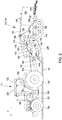
- FIG. 1 shows a self-propelled combine harvester 10 with a frame 12 which is supported by driven front wheels 14 and steerable rear wheels 16 on the ground and is moved away from them.
- the wheels 14 are rotated by means not shown drive means in rotation to the combine 10 z. B. to move over a field to be harvested.
- directional details such as front and rear, refer to the direction of travel V of the combine harvester 10 in the harvesting operation.
- a crop gathering device 18 is detachably connected in the form of a cutter to harvest harvested crops in the form of grain or other threshable culottes from the field and feed it up and down by a feeder 20 to a multi-drum threshing unit.
- a feeder 20 to feed it up and down by a feeder 20 to a multi-drum threshing unit.
- V in the direction of travel
- V arranged one behind the other - a threshing cylinder 22, a stripping drum 24, a superseding working conveyor drum 26, a Tangentialseparator 28 and a turning drum 30 includes.
- the threshing cylinder 22 is surrounded in its lower and rearward area by a concave 34.
- Below the conveyor drum 26 is provided with openings or closed cover 35, while above the conveyor drum 26 is a fixed cover and below the Tangentialseparators 28 is a Separierkorb 36 with adjustable finger elements.
- Below the turning drum 30, a finger rake 38 is arranged.
- a front conveyor floor 40 which performs an alternately forward and rearward swinging motion during operation.
- a rear conveyor floor 42 is disposed below the straw walker 32 and performs in operation also alternately backwards and forwards directed swinging motion.
- the front conveyor floor 40 transports the mixture of grain, short straw and chaff downwards through the concave 34 and through the tangential separator 36, while the rear conveyor floor 42 advances the mixture of grain, short straw and chaff through the straw shaker 32 transported.
- the rear conveyor bottom 42 passes its mixture at its front end to the front conveyor bottom 40, which emits it by a rear finger rake 44 down.
- the mixture discharged from the front conveyor bottom 40 then passes into a cleaning device 46.
- the rear conveyor bottom 42 could also deliver its mixture directly to the cleaning device 46.
- Grain cleaned by the cleaning device 46 is fed by means of a grain screw 48 to an elevator, not shown, which transports it to a grain tank 50.
- a tailing auger 52 returns unmanaged ear parts through another elevator, not shown, back into the threshing process.
- the chaff can be at the back of the screening device are ejected by a rotating chaff spreader, or it is discharged through a straw chopper (not shown) arranged downstream of the straw walker 32.
- the cleaned grain from the grain tank 50 may be unloaded by a discharge system with cross augers 54 and a discharge conveyor 56.
- the systems mentioned are driven by means of an internal combustion engine 58 and controlled and controlled by an operator from a driver's cab 60.
- the various devices for threshing, conveying, cleaning and separating are located within the frame 12. Outside the frame 12 is an outer shell, which is largely hinged.
- the multi-drum thresher shown here with a downstream straw shaker 32 is only one possible embodiment. It could also be replaced by a single transverse threshing drum and a downstream separator with a straw walker, or a single or more transverse threshing drum (s) and a downstream separator with one or more separation rotors, or one or more axial threshing and separating rotors.
- the combine harvester 10 is equipped with a control device 80 which is connected to a storage device 88 and a position determination device 90.
- the position determination device 90 receives signals from a satellite-based position determination system (GPS, Galileo, Glonass or the like) and, if necessary, correction signals and calculates the current position of the combine 10. Based on sensors, which are described below, is stored in the memory device 88 during the Harvesting operation, a map stored in which the positions at which the combine 10 deposits on its back the swath 64, which consists of ejected crop residues (straw), and the associated amounts of straw are registered.
- GPS satellite-based position determination system
- Galileo Galileo, Glonass or the like
- a first sensor 68 is a mechanical sensor for detecting the thickness of the Erntegutmatte above the straw shaker 32. It is located approximately in the middle of the straw shaker 32 and about a horizontally and transversely to the direction extending axis rotatably suspended above the straw shaker 32 and by spring force and the Gravity biased down. A potentiometer or an optical encoder disk is used to detect the angular position of the first sensor 68. Above the straw shaker 32 existing crop rotates the sensor 68 about the axis upwards. Information about the angle of rotation is supplied to the control device 80.
- a second sensor 70 Downstream of the first sensor 68, a second sensor 70, which is identical in construction to the first sensor 68, is arranged above the end region of the straw shaker 32. The rotation angle of the sensor 70 is also detected and corresponding information is supplied to the controller 80.
- a third sensor 72 in the form of a camera is arranged at the rear of the end region of the straw walker 32.
- the sensor 72 captures an image of the crop on the straw shaker 32 and the crop falling down at the end of the straw shaker 32.
- the third sensor 72 is connected to an image processing system that may be implemented within the controller 80 or looped between the sensor 72 and the controller 80.
- the image processing system is configured to extract at least one of the following information from the video signal from the camera and to provide to the controller 80: thickness of the crop mat on the straw walker 32 and the speed at which the crop mat moves backwards on the straw walker 32 (this speed may be by evaluating points in the crop mat, eg, individual striking straws, and detecting their movement).
- a fourth sensor 74 is arranged approximately above the center of the straw shaker 32 and looks from above onto the Erntegutmatte.
- the fourth sensor 74 is a radar sensor having a transmitter for relatively short wavelength electromagnetic waves and a receiver for detecting reflected waves.
- the fourth sensor 74 derives at least one of the following variables from the propagation time, intensity and frequency shift (Doppler effect) of the waves of the transmitter reflected by the crop mat, and sends them to the control device 80: thickness of the crop mat and its speed of movement on the Straw shaker 32 to the rear.
- the fourth sensor 74 is preferably supplied with information about the respective position and / or direction of movement of the straw shaker 32, which is determined by an angle sensor 80 on the shaft of the straw shaker 32 becomes.
- the fourth sensor 74 may use the values of the angle sensor 80 to determine the position and velocity of the straw walker 32 and subtract it from the values measured by the transmitter and receiver.
- a fifth sensor 78 is composed of a horizontally and transversely to the forward direction V arranged shaft with radially outwardly projecting tines and a rotational speed sensor and is disposed above the straw shaker 32.
- the tines are preferably trailing curved and engage in the Erntegutmatte.
- the mean rotational speed of the sensor 78 is therefore correlated with the conveying speed of the crop on the straw shaker 32.
- a sixth sensor 86 detects the throughput of the crop by the inclined conveyor 20. Reference is made to the disclosure of EP 1 266 558 A2 directed.
- a seventh sensor 84 is implemented as a stereo or mono camera with image processing system or scanning radar and / or laser sensor and detects the standing crop stock in front of the cutting unit 18.
- An eighth sensor 82 is a stereo or mono camera with image processing system or scanning radar and / or laser sensor and detected the swath 64 back of the combine 10th
- only one or more of the sensors 68, 70, 72, 74, 78, 86, 84, 82 shown may be present.
- the controller 80 On the basis of the signals of the position-determining device 90 and one or more of the sensors 68, 70, 72, 74, 78, 86, 84 and / or 82, the controller 80 records data regarding the position of the swath 64 and the associated quantities of straw during the harvesting operation.
- the sensors 68, 70, 72, 74, 78, 86, 84 and / or 82 cooperate at locations with the crop, which are arranged offset from the final storage position of the swath 64, and also offset from the position determining means 90, takes place here in each case a conversion of the position detected by the position-determining device 90 into the position of the sensor 68, 70, 72, 74, 78, 86, 84 and / or 82 and a conversion position of the sensor 68, 70, 72, 74, 78, 86, 84 and / or 82 in the position in which the with the sensor 68, 70, 72, 74, 78, 86, 84 and / or 82 cooperating crop or straw is actually stored in the swath 64.
- the known conveying speeds of the crop in the combine harvester 10 which can be determined, for example, by means of one or more of the sensors 78 and 72 for the conveying speed of the straw shaker 32.
- the rotational speed of the drives of the transverse conveyor screw of the cutting unit 18, the inclined conveyor 20 and the threshing unit 22, 26, 28 known to the control device 80 can be taken into account by means of suitable sensors or nominal values.
- the dimensions of the aforementioned conveyors are also known to the control device 80 and stored in the memory 88.
- a map of the field is stored in the storage device 88, in which the positions of the swath 64 and the amounts of straw are stored in a location-specific and georeferenced manner.
- FIG. 2 shows an agricultural work vehicle in the form of an agricultural tractor 110, which draws a baler 112 a baler 114 in the form of a rectangular baler 116.
- a PTO 118 is used to drive moving elements of the baler 114 and in particular a stuffer 120.
- the tractor 110 is mounted on a chassis 122 which is supported on steerable front wheels 124 and drivable rear wheels 126 and carries a cab 128 in which an operator workstation 130 is located.
- an input device 132 in the form of a pedal or a driving lever, which can specify a target speed without permanent operator interaction, in a manual mode, the propulsion speed of the tractor 110 can be specified by an operator.
- the rectangular baler 116 is used to produce cuboidal bales.
- the rectangular baler 116 has a frame 134 which is supported on bottom support wheels 136 in tandem. Attached to the frame 134 is the drawbar 112, which extends forwardly therefrom and is adapted to be connected to the tractor 110 equipped with the PTO shaft 118 for power to drive various driven components of the rectangular baler 116 to provide.
- a pressing space 138 in the form of a chamber of rectangular cross section is partially formed by a housing upper part 140 and a housing lower part 142 formed, wherein the housing lower part 140 is provided with a Guteinlass 144, to which a curved feed channel 146 is connected.
- the side walls of the pressing space 138 and / or the upper housing part 140 may be rigidly mounted or adjustable by actuators, not shown, so that the cross section of the pressing space 138 is variable. By adjusting the actuators, the lateral contact pressure on the bale part 162 and thus the density of the press can be varied.
- a feed device has a crop receptacle 148 in the form of a pickup with an associated hold-down, a compressor fork 150 and a loading fork 152.
- the crop pick-up 148 includes a center-auger auger and is positioned in front of the feed channel 146 for receiving (from the combine harvester 10 of FIG. 1 to pick up swath 64 of crop from the ground and deliver it to the compressor fork 150, which serves to compact crop in the feed channel 146 until a charge of preselected density has accumulated in the feed channel 146 and by means of the forklift 152 via the crop inlet 144 is stuffed into the pressing space 138.
- a spring-loaded flap 156 is pivotally mounted which pivots in response to the density of the crop in the feed channel 146 indicating, once a desired crop density in the feed channel 146 is reached, to a baler control unit 198 114 (cf. FIG. 3 ) to effect the energization of an electrical control circuit which establishes a corresponding drive connection which activates the forks 152 so that it moves the charge of the crop into the pressing space 138.
- directional details such as in the front, always refer back to the forward direction V of the tractor 110 and the rectangular baler 116, which in the FIG. 2 from right to left.
- the pusher 120 When the load of crop has been introduced into the press room 138, the pusher 120 is actuated by a suitable drive in a controlled sequence, after the loading fork 152, to move the crop rearwardly into the press room 138, where it is compacted in a stack , After the stack of compacted material has reached a preselected length, a needle assembly 158 for delivering twine containing a plurality of curved needles is actuated to feed multiple strands of yarn to a corresponding number of unillustrated knots which act to pre-select yarn lengths about that one Set the length of the stack to form a bale 160 which is ready for unloading, which happens when it is pushed out of an unfinished bale part 162 from the rear end portion of the pressing space 138, as it increases in length, because new Loads of crop are stuffed into the pressing space 138.
- the stuffer 120 is for reciprocating movement in the pressing space 138 between a retracted position in front of the Guteinlass 144 and a (in FIG. 2 shown) partially meadow extended position above the Guteinlass 144 designed, from which it can move further back until it abuts against a ball portion 162.
- the result of this movement of the stuffer 120 is that crop loads introduced from the feed channel 146 into the press room 138 are compacted against a stack of crop, including the partially formed ball portion 162 and / or the complete bale 160.
- a storage device 164 is attached to the rear end of the frame 134 as a rear extension of the lower housing part 142.
- the stoppers 120 are driven via the PTO shaft 118 of the agricultural tractor 110, which via an articulated shaft 166 drives an input shaft 168 of the drive device 170 of the stoppers 120.
- the input shaft 168 drives a flywheel 172 and via a gear 174 a crank 178, whose movement is transmitted via a connecting rod 176 to the stuffer 120.
- FIG. 3 2 shows a schematic of the traction system of the tractor 110 and the baler 114.
- a drive motor 180 of the tractor 110 which may be a combustion (diesel) engine or an electric motor, drives with its output shaft 204 a transfer case 182 having a first propulsion output shaft 210 and a load output shaft 206 has.
- the transfer case 182 may include a direct connection to the output shaft 204.
- the propulsion output shaft 210 drives via a drive clutch 184 to a transmission input shaft 212, which drives a variable transmission (for example, as a powershift or continuously variable transmission) propelling gear 186 on the output side via a shaft 214, a differential gear 188 and 216 Radantriebswellen the rear wheels 126 drives ,
- the propelling gear 186 may also drive the front wheels 124 via drive means (not shown).
- the load output shaft 206 is in drive connection via a PTO clutch 190 and a power take-off 192 with the PTO 118, which serves to drive the gear 174 of the drive means 170 and other driven elements of the baler 114.
- the transfer case 182, the propulsion output shaft 210, the clutch 184, the propelling gear 186, the shaft 214, the differential gear 188 and the Radantriebswellen 216 form a drivable by the drive motor 180 propulsion driveline for driving propulsion means (wheels 126) of the tractor 110, a by means of the actuator 1200 has changeable translation.
- Transfer case 182, load output shaft 206, clutch 190, PTO gearbox 192, PTO 118 and transmission 174 (with the following components for driving stuffer 120) form a load drive train drivable by drive motor 180 to drive baler 114.
- An electronic controller 194 is provided with a control unit 198 of the baler 114, an actuator 200 for adjusting the transmission ratio of the power take-off 186, a motor controller 202, a speed sensor 196 for detecting the position of the input device 132 and for clarity not shown actuators for closing and opening the clutches 184 and 190 connected, although the latter could also be operated by the operator by hand or foot.
- the controller 198 of the baler is connected to the controller 194 of the tractor 110 via a bus system 226.
- the controller 194 is connected to a memory 224 and a position-determining device 222, which are similar to the position-determining device 90 of the combine harvester 10 of FIG. 1 can be.
- a map is stored for a field on which the swath 64 generated by the combine 10, from the memory device 88 of the combine 10 of the FIG. 1 comes.
- the transfer of the card can be done physically by means of a memory card carried by the combine harvester 10 to the tractor 110 or wirelessly, eg via a cellular or wireless connection.
- the card can be prepared prior to storage in the memory 224, for example on a farm computer or at a service provider to include, for example, taking into account weather conditions (temperature, solar radiation, location of the swath on the field, etc.), in which way the straw dried since the harvest.
- weather conditions temperature, solar radiation, location of the swath on the field, etc.
- step 302 the position of the tractor 110 determined by means of the position determining device 222 reads out from the storage device 224 what amount of straw lies in the windrow 64 in front of the agricultural tractor 110.
- step 304 based on the amount of straw thus determined, a speed of the tractor 110 is determined which corresponds to a desired throughput of straw at the receiver 148 of the baler 114.
- the actuators 200 and / or 202 are set accordingly. In this way, one can anticipate a suitable speed of the baler 114 for receiving the respective amount of straw.
- the baler 114 may be equipped with a moisture sensor 220 for detecting the straw moisture of the swath 64, the measured values of which are transferred by the control device 198 via the bus 226 to the controller 194 and from this to influence the speed of the tractor 110 and thus the Baler 114 are taken into account.
- moisture values registered on the map and obtained during the harvesting process by means of the combine harvester 10 can be used, the sensor 220 providing reference values by means of which the mapped moisture in the swath can be calibrated.
- the baler 114 can be equipped, for example, in its pre-compression chamber 146 with a sensor for determining the mass flow rate, which detects the force on the scraper 150, 152 and / or subchamber subsoil (sensor 156) and calculates the mass throughput (cf. EP 3 001 894 A1 ).
- the controller 194 can calculate a driving speed and command it in a manner known per se taking into account the stored (predicted) straw quantities.
- the control system will now unlike previously known system retard greatly, so that the Erntegutmenge can be taken clean and pressed clean without additional operator intervention.
- FIGS. 2 to 4 shown tasks of the control unit 194 of the tractor 110 may alternatively be accepted by the control device 198 of the baler 114.
- the controller 198 would calculate the desired speed of the baler 114 and transmit it via the bus 226 to the control unit 194, which in turn commands the speed of the tractor 110.
- the position determining device 222 could then be directly on board the baler 114 and connected directly to the controller 198 or remain on board the tractor 110 and transmit its data to the control unit 198 via the bus 226 or other connection.
Landscapes
- Life Sciences & Earth Sciences (AREA)
- Environmental Sciences (AREA)
- Engineering & Computer Science (AREA)
- Mechanical Engineering (AREA)
- Soil Sciences (AREA)
- Radar, Positioning & Navigation (AREA)
- Aviation & Aerospace Engineering (AREA)
- Remote Sensing (AREA)
- Physics & Mathematics (AREA)
- General Physics & Mathematics (AREA)
- Automation & Control Theory (AREA)
- Harvester Elements (AREA)
- Harvesting Machines For Specific Crops (AREA)
Abstract
Ein Verfahren und eine Anordnung zur Kontrolle der Geschwindigkeit einer Ballenpresse (114) umfassen folgende Schritte bzw. dazu geeignete Mittel: Erfassen und Kartieren von wenigstens einer Ernteguteigenschaft und/oder daraus abgeleiteter Daten während der Ernte von einem Feld mittels eines Mähdreschers (10), bei welcher Erntegutreste in einem Schwad (64) abgelegt werden, und Kontrollieren der Geschwindigkeit der Ballenpresse (114) bei der Aufnahme des Schwads (64) unter Berücksichtigung der kartierten Ernteguteigenschaft und/oder der daraus abgeleiteten Daten.A method and arrangement for controlling the speed of a baler (114) comprise the following steps or suitable means: Detecting and mapping at least one crop property and / or data derived therefrom during harvest from a field by means of a combine harvester (10) storing crop debris in a swath (64); and controlling the speed of the baler (114) upon picking up the swath (64), taking into account the mapped crop property and / or the data derived therefrom.
Description
Quaderballenpressen werden zur Ernte von landwirtschaftlichem Erntegut wie Heu, Silage oder Stroh eingesetzt. Dabei wird die Quaderballenpresse von einem Traktor gezogen und über eine Zapfwelle mechanisch angetrieben. Das Erntegut wird üblicherweise in einer Vorpresskammer vorverdichtet und danach in der leicht konvergierenden Hauptpresskammer von einem reziprok arbeitenden Presskolben gegen den bereits existierenden Ballen verdichtet.Square balers are used to harvest agricultural crops such as hay, silage or straw. The square baler is pulled by a tractor and mechanically driven by a power take-off. The crop is usually precompressed in a pre-compression chamber and then compacted in the slightly converging main compression chamber by a reciprocating plunger against the already existing bale.
Um die Presse mit höchstmöglicher Produktivität betreiben zu können, muss eine Fahrgeschwindigkeit gewählt werden, die abhängig von der Schwadgröße und -dichte angepasst wird. Im Stand der Technik gibt es von verschiedenen Herstellern Regelsysteme, welche die Vorfahrtsgeschwindigkeit des Traktors basierend auf einem Sensorsignal der Quaderballenpresse regelt. Das Sensorsignal wird dabei von einem in die Pick-up, Vorpresskammer oder Hauptpresskammer integrierten Sensor generiert und stellt einen Kennwert für die Auslastung der Presse dar. Solche Sensoren sind im Stand der Technik vielzählig bekannt (vgl.
Um diese Problem zu lösen, wurde vorgeschlagen, mittels Sensorik den Schwad vor dem Traktor zu erfassen und zu charakterisieren. Dies kann beispielsweise mittels (Stereo-) Kamera (
Der kostenintensive sensorische Aufwand und Anfälligkeiten auf Umwelteinflüsse wie Staub und Schmutz haben bisher eine verbreitete kommerzielle Nutzung solcher vorausschauender Systeme verhindert. Ebenfalls nachteilig ist bei der im Stand der Technik bekannten sensorischen Erfassung des Schwades, dass nur geometrische Informationen zu dem Schwad wie beispielsweise Breite, Höhe oder Querschnittsfläche bzw. Volumen bestimmt werden können. Für eine optimale Durchsatzregelung der Ballenpresse ist jedoch die Schwaddichte und ggf. die -feuchtigkeit ebenfalls relevant.The costly sensory effort and susceptibility to environmental influences such as dust and dirt have hitherto prevented widespread commercial use of such predictive systems. Also disadvantageous in the known in the prior art sensory detection of the swath that only geometric information about the swath such as width, height or cross-sectional area or volume can be determined. However, for optimum throughput control of the baler, the swath density and possibly the moisture is also relevant.
Das Problem einer Geschwindigkeitsoptimierung liegt auch bei Rundballenpressen vor (s.
Die
Die Aufgabe wird folglich darin gesehen, ein kostengünstiges und robustes Durchsatzregelsystem für Ballenpressen zu entwickeln, welches mit großen Variationen im Schwad zurechtkommt.The object is therefore seen to develop a cost effective and robust throughput control system for balers, which cope with large variations in the windrow.
Die vorliegende Erfindung wird durch die Patentansprüche definiert.The present invention is defined by the claims.
Es wird eine automatisierte Kartierung der Schwade bei deren Erstellung und eine Verarbeitung dieser Daten zur prädiktiven Durchsatzregelung für Ballenpressen vorgeschlagen. Im Ausführungsbeispiel wird die Vorgehensweise beim Einsatz in Getreidestroh d.h. bei der Ernte mit einem Mähdrescher und anschließendem Pressvorgang mit einer Quaderballenpresse beschrieben. Analog kann die Vorgehensweise aber auch auf andere Pressenarten, wie Rundballenpressen, angewendet werden. Auch kann sie bei der Maisernte verwendet werden.It will be an automated mapping of the swath in their creation and processing of this data for predictive throughput control for balers proposed. In the exemplary embodiment, the procedure for use in grain straw ie when harvesting with a combine harvester and subsequent pressing process is described with a square baler. Analogously, the procedure can also be applied to other press types, such as round balers. Also, it can be used in the corn harvest.
In einem ersten Schritt werden Daten erzeugt, welche zur Charakterisierung der im Schwad abgelegten Erntegutreste (bei denen es sich in der Regel um Stroh handelt) weiterverarbeitet werden können. Dies geschieht mittels einer Sensierung und georeferenzierten Datenaufzeichnung auf dem Mähdrescher. Es werden das verarbeitete Erntegut sensiert, die Fahrzeugposition des Mähdreschers sowie dessen Orientierung mittels GNSS-Empfänger erfasst und die Position bzw. Trajektorie der Schwadablage in einem erdfesten Koordinatensystem berechnet und gemeinsam mit den sensierten Daten (und/oder aus den sensierten Daten abgeleiteten Daten, die beliebige Eigenschaften des Ernteguts oder Werte der anzusteuernden Geschwindigkeit der Ballenpresse betreffen können) in einer Speichereinrichtung aufgezeichnet. Im Falle einer Erfassung des Erntegutbestands vor dem Schneidwerk können die Position oder Trajektorie des Messerbalkens sowie und Informationen über die Schneidwerksbreite sowie Maschinendimensionen des Mähdreschers berücksichtigt werden, um die Position des Schwads und dessen Strohmenge zu bestimmen.In a first step, data are generated which can be further processed to characterize the crop residue left in the swath (which is usually straw). This is done by means of a sensing and geo-referenced data recording on the combine harvester. It senses the processed crop, detects the vehicle position of the combine and its orientation by GNSS receiver and calculates the position or trajectory of the swathing in a Erdfesten coordinate system and together with the sensed data (and / or from the sensed data derived data any characteristics of the crop or values of the speed of the baler to be controlled) may be recorded in a memory device. In the case of detecting the crop stock in front of the header, the position or trajectory of the cutter bar as well as information about the cutter width and machine dimensions of the combine can be taken into account to determine the position of the swath and its amount of straw.
Zwischen dem Schnittvorgang bzw. Aufnahme des Strohs auf dem Tisch des Schneidwerks (bzw. der Sensierung des Ernteguts, die zur Kartierung der Strohmengen dient) und der Ablage des Schwads auf dem Feld vergeht eine gewisse Verzögerungszeit, die bei der Aufzeichnung der Position des Schwades berücksichtigt werden kann. Die erwähnte Verzögerungszeit hängt zudem von gewissen Maschineneinstellungen des Mähdreschers ab. Über eine Erfassung und Auswertung der relevanten Maschinenparameter des Mähdreschers lässt sich diese Verzögerungszeit ausreichend genau bestimmen. Folgende Parameter können dabei abhängig von dem eingesetzten Mähdreschertyp berücksichtigt werden:
Fördergeschwindigkeit (Schnecke oder Förderband) am Schneidwerk, Drehzahl des Schrägförderers, Rotordrehzahl des Dresch- und Abscheiderotors (bei einem Axialmähdrescher), Trommeldrehzahl des Dreschorgans (bei Schüttler- oder Hybridmähdrescher), Rotordrehzahl des Abscheideorgans (bei Hybridmähdrescher), Drehzahl des Schüttlerantriebs (bei Schüttlermähdrescher).Between the cutting process or picking up the straw on the table of the cutting (or the sensing of the crop, which is used for mapping the amounts of straw) and the deposition of swath on the field passes a certain delay time, which takes into account when recording the position of the swath can be. The mentioned delay time also depends on certain machine settings of the combine. By recording and evaluating the relevant machine parameters of the combine harvester, this delay time can be determined with sufficient accuracy. The following parameters can be taken into account depending on the combine harvester type used:
Conveying speed (worm or conveyor belt) on the cutting unit, speed of the feederhouse, rotor speed of the threshing and separating rotor (in the case of an axial combine), drum speed of the threshing unit (shaker or hybrid combine harvester), rotor speed of the separator (for hybrid combine harvester), speed of the shaker drive (for shaker combine ).
Um die Strohmenge im Schwad zu bestimmen, werden ebenfalls Sensorwerte und/oder Betriebsparameter des Mähdreschers herangezogen.In order to determine the amount of straw in the swath, sensor values and / or operating parameters of the combine harvester are also used.
Auch können auf dem Mähdrescher allfällig installierte bildgebende (z.B. Stereokameras) oder andere den Arbeitsbereich bzw. Schwadablagebereich überwachende Sensoren dazu verwendet werden, um das Volumen und anderweitige geometrische Größen des Bestands bzw. des abgelegten Schwades zu erfassen.Also, on the combine, any installed imaging (e.g., stereo cameras) or other sensors monitoring the work area or swath deposition area may be used to detect the volume and other geometric sizes of the swath.
Des Weiteren können Daten zu Kornertrag, Kornfeuchte und Strohfeuchte ebenfalls gespeichert und weiterverarbeitet werden. Beispielsweise kann mittels bekannter Schneidwerksbreite zusammen mit der Schneidwerks- und Haspelhöhe sowie der Fahrgeschwindigkeit und einer sensorisch erfassten Bestandsdichte und -höhe (s. beispielsweise
Durch die direkte Feuchtigkeitsmessung des Strohs bzw. die indirekte Abschätzung der Strohfeuchte über Messung der Kornfeuchte lässt sich eine relative Feuchtigkeitsverteilung des Schwades erreichen. Der Schwad wird in der Regel bis zum Pressvorgang abtrocknen, womit die auf dem Mähdrescher ermittelten absoluten Feuchtigkeitswerte nicht mehr aktuell sind. Auf der Ballenpresse ist jedoch vorteilhafterweise ebenfalls ein Feuchtigkeitssensor verbaut (siehe unten) welcher Referenzwerte liefert, mittels welcher die Feuchte im Schwad kalibriert werden kann.The direct moisture measurement of the straw or the indirect estimation of the straw moisture by measuring the grain moisture allows a relative moisture distribution of the swath to be achieved. The swath will usually dry to the pressing process, which means that the absolute humidity values determined on the combine harvester are out of date. On the baler, however, a moisture sensor is advantageously also installed (see below) which provides reference values, by means of which the moisture in the swath can be calibrated.
Insbesondere lassen sich somit Nester von feuchtem Stroh kartieren und die Durchsatzregelung der Quaderballenpresse prädiktiv darauf anpassen. Solche "feuchten Nester" sind heute eine wesentliche Schwierigkeit für den Fahrer der Quaderballenpresse, da sie oft zu spät erkannt werden und dann den Einzug oder die Vorpresskammer der Ballenpresse verstopfen. Dies führt zu Stillstandzeiten und somit zu Produktivitätsverlust.In particular, nests of wet straw can thus be mapped and the throughput control of the square baler can be predicted to suit it. Such "wet nests" today are a major difficulty for the driver of the square baler, as they are often recognized too late and then clog the feeder or the pre-compression chamber of the baler. This leads to downtime and thus loss of productivity.
Für die Strohernte mit der Ballenpresse ebenfalls relevant ist die Strohqualität. Unter dem Begriff Strohqualität ist neben Aspekten wie Strohfeuchte insbesondere die durchschnittliche Strohlänge bzw. die Längenverteilung der einzelnen Strohhalme zu verstehen. Die Strohqualität kann vorteilhaft mittels eines Kamerasystems bildverarbeitend ermittelt werden oder basierend auf Feuchtigkeit und Mähdreschertyp abgeschätzt werden. Wahlweise können auch Betriebsparameter des Mähdreschers, wie der aktuelle Dreschkorbabstand verglichen zum Empfehlungswert für die Fruchtart, sowie der Prozentsatz an Bruchkorn, welcher mittels einer Kornqualitätskamera ermittelt wird, zur Abschätzung der Strohqualität herangezogen werden. Es ist davon auszugehen, dass ein hoher Bruchkornanteil und/oder ein geringer Dreschkorbabstand zu einer schlechteren Strohqualität aus Gründen der höheren mechanischen Belastung des Strohs während des Dreschvorgangs führen.The straw quality is also relevant for the straw harvest with the baler. The term straw quality is to be understood in addition to aspects such as straw moisture in particular the average straw length and the length distribution of the individual straws. The straw quality can advantageously be determined by image processing using a camera system or estimated based on moisture and type of combine harvester. Optionally, also operating parameters of the combine harvester, such as the current threshing concavity compared to the recommendation value for the crop, as well as the percentage of broken grain, which is determined by means of a grain quality camera, are used to estimate the straw quality. It can be assumed that a high fraction of broken grains and / or a small concave spacing lead to a poorer straw quality due to the higher mechanical load of the straw during the threshing process.
Basierend auf einer sensorisch ermittelten oder aber modellbasiert berechneten Strohqualität lässt sich die Durchsatzregelung der Ballenpresse verfeinern. Auch können die Daten dem Fahrer der (Quader-) Ballenpresse angezeigt werden, um eine Entscheidung ob Schnittmesser eingesetzt werden sollen, zu erleichtern oder die Schnittmesser selbsttätig zu aktivieren oder zu deaktivieren.Based on a sensory or model-based calculated straw quality, the throughput control of the baler can be refined. Also, the data can be displayed to the driver of the (square) baler in order to make a decision as to whether or not to use cutting blades or to automatically activate or deactivate the cutting blades.
Aus diesen obig genannten Informationen wird und eine Art Applikationskarte für die Ballenpresse erstellt. Anhand dieser wird die Durchsatzregelung der Ballenpresse prädiktiv vorgesteuert. Die Traktorgeschwindigkeit wird mittels an sich bekannter Geschwindigkeitssteuerung derart moduliert, dass ein maximaler Durchsatz erreicht wird.From this information above and a kind of application card for the baler is created. Based on this, the throughput control of the baler is predictively piloted. The tractor speed is modulated by means of per se known speed control such that a maximum throughput is achieved.
Die Erstellung dieser Applikationskarte kann auf einem Steuergerät des Mähdreschers, einem beabstandeten Rechensystem, auf einem Tablet-Computer oder auch einem Steuergerät des Traktors bzw. der Ballenpresse erfolgen.The preparation of this application card can be done on a control unit of the combine, a spaced computing system, on a tablet computer or even a control unit of the tractor or the baler.
Neben der Schwadposition können unter anderem folgende für die prädiktive Durchsatzregelung relevanten Kenngrößen georeferenziert berechnet und an die Ballenpresse übertragen werden: Art des Ernteguts (z.B. Weizenstroh, Gerstenstroh,...), relative Schwadmasse, Strohlänge, Feuchtigkeit des Schwades, geometrische Schwadinformation (Breite, Höhe, Querschnitt), Indikation von "feuchten Nestern", Indikation einer Schwadanhäufung (z.B. weil der Mähdrescher anhalten musste).In addition to the windrow position, the following parameters that are relevant for the predictive throughput control can be calculated georeferenced and transferred to the baler: type of crop (eg wheat straw, barley straw, ...), relative swath mass, straw length, swath moisture, geometric swath information (width, Height, cross section), indication of "wet nests", indication of a swath accumulation (eg because the combine harvester had to stop).
Einige oder alle der vorstehend erwähnten Daten werden an die Ballenpresse bzw. ein sie ziehendes Fahrzeug übertragen, ausgewertet und zur Durchsatzregelung angewendet. Hierbei wird die Position der Ballenpresse bestimmt und mit der Applikationskarte verglichen. Die ermittelten relativen Kennwerte (relative Schwadmasse, Feuchtigkeit des Schwades zum Schnittzeitpunkt) werden mit aktuellen, sensorisch erfassten Kenngrößen abgeglichen und kalibriert.Some or all of the above-mentioned data is transmitted to the baler or a towing vehicle, evaluated and applied for throughput control. Here, the position of the baler is determined and compared with the application map. The determined relative characteristic values (relative swath mass, moisture of the swath at the time of cutting) are compared and calibrated with current, sensory acquired parameters.
Bei eine Vorpresskammer einer Quaderballenpresse mit Sensorik zur Bestimmung des Massedurchsatzes kann die Kraft an Raffer und Vorkammerunterboden gemessen und daraus der Massedurchsatz berechnet werden (vgl.
Anhand der aktuellen Massedurchsatzdaten und prädiktierten Strohmengen wird eine Fahrgeschwindigkeit berechnet und in an sich bekannter Weise (beispielsweise über ISOBUS class 3, Tractor Implement Automation) an den Traktor kommandiert. Insbesondere bei "feuchten Nestern" oder großen Strohanhäufungen wird das Regelsystem nun anders als bei bisher bekannten System sehr stark verzögern, so dass die Erntegutmenge ohne zusätzlichen Bedienereingriff sauber aufgenommen und gepresst werden kann.On the basis of the current mass throughput data and predicted amounts of straw, a driving speed is calculated and commanded in a manner known per se (for example via ISOBUS class 3, Tractor Implement Automation) to the tractor. In particular, in "wet nests" or large Strohanhäufungen the control system will now unlike previously known system retard greatly, so that the Erntegutmenge can be taken clean and pressed clean without additional operator intervention.
Das Regelsystem kann wie im Stand der Technik an sich bekannt in verschiedenen Betriebsmodi gefahren werden, die auf Optimierung des Durchsatzes, der Ballenqualität oder einer Mischregelung ausgelegt sind.As is known per se in the prior art, the control system can be operated in various operating modes that are designed to optimize the throughput, the bale quality or a mixed control.
In den Zeichnungen ist ein nachfolgend näher beschriebenes Ausführungsbeispiel der Erfindung dargestellt, wobei die Bezugszeichen nicht zu einer einschränkenden Auslegung heranzuziehen sind. Es zeigt:
- Fig. 1
- eine schematische seitliche Ansicht eines Mähdreschers,
- Fig. 2
- eine seitliche Ansicht eines Ackerschleppers mit einer angehängten Rechteckballenpresse,
- Fig. 3
- ein Schema des Antriebssystems des Ackerschleppers, und
- Fig. 4
- ein Flussdiagramm, nach dem die Steuerung des Antriebssystems arbeitet.
- Fig. 1
- a schematic side view of a combine harvester,
- Fig. 2
- a side view of a farm tractor with an attached rectangular baler,
- Fig. 3
- a scheme of the traction system of the tractor, and
- Fig. 4
- a flow chart, after which the control of the drive system works.
Die
An den vorderen Endbereich des Mähdreschers 10 ist eine Erntegutbergungsvorrichtung 18 in Form eines Schneidwerks abnehmbar angeschlossen, um beim Erntebetrieb Erntegut in Form von Getreide oder andere, dreschbare Halmfrüchte von dem Feld zu ernten und es nach oben und hinten durch einen Schrägförderer 20 einem Mehrtrommeldreschwerk zuzuführen, das - in Fahrtrichtung V hintereinander angeordnet - eine Dreschtrommel 22, eine Abstreiftrommel 24, eine oberschlächtig arbeitende Fördertrommel 26, einen Tangentialseparator 28 sowie eine Wendetrommel 30 umfasst. Stromab der Wendetrommel 30 befindet sich ein Strohschüttler 32, der sich aus mehreren (z. B. 5 oder 6) einzelnen Schüttlern zusammensetzt, die phasenverschoben über eine Kurbelwelle 102 (s.
Unterhalb des Mehrtrommeldreschwerks befindet sich ein vorderer Förderboden 40, der im Betrieb eine abwechselnd nach vorn und hinten gerichtete Schwingbewegung durchführt. Ein hinterer Förderboden 42 ist unterhalb des Strohschüttlers 32 angeordnet und vollführt im Betrieb ebenfalls eine abwechselnd nach hinten und vorn gerichtete Schwingbewegung. Der vordere Förderboden 40 transportiert das durch den Dreschkorb 34 und durch den Tangentialseparator 36 nach unten hindurch tretende Gemisch aus Korn, Kurzstroh und Spreu nach hinten, während der hintere Förderboden 42 das durch den Strohschüttler 32 hindurch strömende Gemisch aus Korn, Kurzstroh und Spreu nach vorn transportiert. Der hintere Förderboden 42 übergibt sein Gemisch an seinem vorderen Ende an den vorderen Förderboden 40, der es durch einen rückwärtigen Fingerrechen 44 nach unten abgibt. Das vom vorderen Förderboden 40 abgegebene Gemisch gelangt dann in eine Reinigungseinrichtung 46. Der hintere Förderboden 42 könnte sein Gemisch auch direkt an die Reinigungseinrichtung 46 abgeben.Below the multi-drum thresher is a
Durch die Reinigungseinrichtung 46 gereinigtes Getreide wird mittels einer Körnerschnecke 48 einem nicht gezeigten Elevator zugeführt, der es in einen Korntank 50 befördert. Eine Überkehrschnecke 52 gibt unausgedroschene Ährenteile durch einen weiteren nicht gezeigten Elevator zurück in den Dreschprozess. Die Spreu kann an der Rückseite der Siebeinrichtung durch einen rotierenden Spreuverteiler ausgeworfen werden, oder sie wird durch einen stromab des Strohschüttlers 32 angeordneten Strohhäcksler (nicht eingezeichnet) ausgetragen. Das gereinigte Getreide aus dem Korntank 50 kann durch ein Entladesystem mit Querschnecken 54 und einem Entladeförderer 56 entladen werden.Grain cleaned by the
Die genannten Systeme werden mittels eines Verbrennungsmotors 58 angetrieben und von einem Bediener aus einer Fahrerkabine 60 heraus kontrolliert und gesteuert. Die verschiedenen Vorrichtungen zum Dreschen, Fördern, Reinigen und Abscheiden befinden sich innerhalb des Rahmens 12. Außerhalb des Rahmens 12 befindet sich eine Außenhülle, die größtenteils aufklappbar ist.The systems mentioned are driven by means of an
Es bleibt anzumerken, dass das hier dargestellte Mehrtrommeldreschwerk mit nachgeordnetem Strohschüttler 32 nur ein mögliches Ausführungsbeispiel ist. Es könnte auch durch eine einzige quer angeordnete Dreschtrommel und eine nachgeordnete Trenneinrichtung mit einem Strohschüttler oder eine einzige oder mehrere quer angeordnete Dreschtrommel(n) und eine nachgeordnete Trenneinrichtung mit einem oder mehreren Trennrotoren oder durch einen oder mehrere Axialdresch- und Trennrotoren ersetzt werden.It should be noted that the multi-drum thresher shown here with a
Der Mähdrescher 10 ist mit einer Steuereinrichtung 80 ausgestattet, die mit einer Speichereinrichtung 88 und einer Positionsbestimmungseinrichtung 90 verbunden ist. Die Positionsbestimmungseinrichtung 90 empfängt Signale von einem satellitenbasierten Positionsbestimmungssystem (GPS, Galileo, Glonass o.ä.) und ggf. Korrektursignale und berechnet die aktuelle Position des Mähdreschers 10. Anhand von Sensoren, die im Folgenden beschrieben werden, wird in der Speichereinrichtung 88 während des Erntebetriebes eine Karte abgespeichert, in welcher die Positionen, an denen der Mähdrescher 10 an seiner Rückseite das Schwad 64 ablegt, welches aus ausgestoßenen Erntegutreste (Stroh) besteht, und die zugehörigen Strohmengen eingetragen sind.The
Ein erster Sensor 68 ist ein mechanischer Fühler zur Erfassung der Dicke der Erntegutmatte oberhalb des Strohschüttlers 32. Er ist etwa in der Mitte des Strohschüttlers 32 angeordnet und um eine horizontal und quer zur Fahrtrichtung verlaufende Achse drehbar oberhalb des Strohschüttlers 32 aufgehängt und durch Federkraft und die Schwerkraft nach unten vorgespannt. Ein Potentiometer oder eine optische Kodierscheibe dient zur Erfassung der Winkelstellung des ersten Sensors 68. Oberhalb des Strohschüttlers 32 vorhandenes Erntegut dreht den Sensor 68 um die Achse nach oben. Eine Information über den Drehwinkel wird der Steuereinrichtung 80 zugeführt.A
Stromab des ersten Sensors 68 ist oberhalb des Endbereichs des Strohschüttlers 32 ein zweiter Sensor 70 angeordnet, der mit dem ersten Sensor 68 baugleich ist. Der Drehwinkel des Sensors 70 wird ebenfalls erfasst und eine entsprechende Information wird der Steuereinrichtung 80 zugeführt.Downstream of the
Ein dritter Sensor 72 in Form einer Kamera ist rückwärtig des Endbereichs des Strohschüttlers 32 angeordnet. Der Sensor 72 erfasst ein Bild des Ernteguts auf dem Strohschüttler 32 und des am Ende des Strohschüttlers 32 herunterfallenden Ernteguts. Der dritte Sensor 72 ist mit einem Bildverarbeitungssystem verbunden, das innerhalb der Steuereinrichtung 80 realisiert oder zwischen den Sensor 72 und die Steuereinrichtung 80 eingeschleift sein kann. Das Bildverarbeitungssystem ist eingerichtet, mindestens eine der folgenden Informationen aus dem Videosignal der Kamera zu extrahieren und der Steuereinrichtung 80 zuzuführen: Dicke der Erntegutmatte auf dem Strohschüttler 32 sowie die Geschwindigkeit, mit der sich die Erntegutmatte auf dem Strohschüttler 32 nach hinten bewegt (diese Geschwindigkeit kann durch Identifizieren von Punkten in der Erntegutmatte, z. B. einzelne markante Strohhalme, und Erfassen ihrer Bewegung evaluiert werden).A
Ein vierter Sensor 74 ist etwa oberhalb der Mitte des Strohschüttlers 32 angeordnet und blickt von oben her auf die Erntegutmatte. Der vierte Sensor 74 ist ein Radarsensor mit einem Sender für relativ kurzwellige elektromagnetische Wellen und einem Empfänger zur Erfassung reflektierter Wellen. Der vierte Sensor 74 leitet aus der Laufzeit, Intensität und Frequenzverschiebung (Dopplereffekt) der mit dem Empfänger empfangenen, von der Erntegutmatte reflektierten Wellen des Senders mindestens eine der folgenden Größen ab und führt sie der Steuereinrichtung 80 zu: Dicke der Erntegutmatte und ihre Bewegungsgeschwindigkeit auf dem Strohschüttler 32 nach hinten. Um die Dicke und Geschwindigkeit der Erntegutmatte auf dem Strohschüttler 32 möglichst fehlerarm bestimmen zu können, wird dem vierten Sensor 74 vorzugsweise eine Information über die jeweilige Stellung und/oder Bewegungsrichtung des Strohschüttlers 32 zugeführt, die mit einem Winkelsensor 80 an der Welle des Strohschüttlers 32 ermittelt wird. Der vierte Sensor 74 kann mittels der Werte des Winkelsensors 80 die Position und Geschwindigkeit des Strohschüttlers 32 bestimmen und von den anhand des Senders und Empfängers gemessenen Werten abziehen.A
Ein fünfter Sensor 78 setzt sich aus einer horizontal und quer zur Vorwärtsrichtung V angeordneten Welle mit radial nach außen abstehenden Zinken und einem Drehgeschwindigkeitssensor zusammen und ist oberhalb des Strohschüttlers 32 angeordnet. Die Zinken sind vorzugsweise nachlaufend gekrümmt und greifen in die Erntegutmatte ein. Die mittlere Drehgeschwindigkeit des Sensors 78 ist demnach mit der Fördergeschwindigkeit des Ernteguts auf dem Strohschüttler 32 korreliert.A
Ein sechster Sensor 86 erfasst den Durchsatz des Ernteguts durch den Schrägförderer 20. Hierzu sei auf die Offenbarung der
Bei möglichen Ausführungsformen können nur einer oder mehrere der gezeigten Sensoren 68, 70, 72, 74, 78, 86, 84, 82 vorhanden sein.In possible embodiments, only one or more of the
Es wäre (zusätzlich oder alternativ zu den erwähnten Sensoren) auch denkbar, die Strohmengen anhand von Maschinenparameter des Mähdreschers zu ermitteln. Relevante Betriebsparameter sind insbesondere die für Förderorgane, z.B. Dresch- und Abscheideorgane und/oder Schrägförderer verwendete Motorleistung, beziehungsweise die gesamt verwendete Motorleistung ohne Aufschlüsselung in die Einzelkomponenten, das Drehmoment bzw. der Rotordruck des Dresch- und Abscheiderotors (bei einem Axialmähdrescher), das Drehmoment des Dreschorgans 22 (bei einem Schüttler- oder Hybridmähdrescher), das Drehmoment des Abscheideorgans 28 (bei einem Mehrtrommel- oder Hybridmähdrescher), das Drehmoment des Antriebs des Schüttlers 32 (bei Schüttlermähdrescher), das Signal von einem Kornertrags- und Kornfeuchtesensor, die Fahrgeschwindigkeit, die Schneidwerks- und Haspelhöhe und die Fruchtart zur Ermittlung des Korn- Stroh- Verhältnisses. Aus dem sensorisch oder antriebsleistungsabhängig erfassten Kornertrag kann demnach auf die Strohmenge zurückgeschlossen werden, insbesondere unter Verwendung einer oder mehrerer der erwähnten Daten.It would also be conceivable (in addition to or as an alternative to the sensors mentioned) to determine the quantities of straw on the basis of machine parameters of the combine harvester. Relevant operating parameters are in particular those for conveying devices, e.g. Threshing and separating and / or inclined conveyor used engine power, or the total engine power used without breakdown into the individual components, the torque or the rotor pressure of the threshing and Abscheiderotors (in an axial combine harvester), the torque of the threshing 22 (in a shaker or Hybrid combine harvester), torque of separator 28 (in a multi-drum or hybrid combine), torque of
Anhand der Signale der Positionsbestimmungseinrichtung 90 und eines oder mehrerer der Sensoren 68, 70, 72, 74, 78, 86, 84 und/oder 82 erfasst die Steuerung 80 während des Erntebetriebs Daten hinsichtlich der Position des Schwads 64 und der zugehörigen Strohmengen. Da die Sensoren 68, 70, 72, 74, 78, 86, 84 und/oder 82 an Stellen mit dem Erntegut zusammenwirken, die gegenüber der endgültigen Ablageposition des Schwads 64 versetzt angeordnet sind, und auch gegenüber der Positionsbestimmungseinrichtung 90 versetzt sind, erfolgt hierbei jeweils eine Umrechnung der mittels der Positionsbestimmungseinrichtung 90 erfassten Position in die Position des Sensors 68, 70, 72, 74, 78, 86, 84 und/oder 82 und eine Umrechnung Position des Sensors 68, 70, 72, 74, 78, 86, 84 und/oder 82 in jene Position, an der das mit dem Sensor 68, 70, 72, 74, 78, 86, 84 und/oder 82 zusammenwirkende Erntegut bzw. Stroh tatsächlich im Schwad 64 abgelegt wird. Hierbei kann auf die bekannten Fördergeschwindigkeiten des Ernteguts im Mähdrescher 10 zurückgegriffen werden, die z.B. mittels eines oder mehreren der Sensoren 78 und 72 für die Fördergeschwindigkeit des Strohschüttlers 32 ermittelt werden können. Analog können die der Steuereinrichtung 80 durch geeignete Sensoren oder Sollwerte bekannten Drehzahlen der Antriebe der Querförderschnecke des Schneidwerks 18, des Schrägförderers 20 und des Dreschwerks 22, 26, 28 berücksichtigt werden. Die Abmessungen der erwähnten Fördereinrichtungen sind der Steuereinrichtung 80 ebenfalls bekannt und im Speicher 88 abgelegt.On the basis of the signals of the position-determining
Demnach ist nach Ende eines Erntevorgangs in der Speichereinrichtung 88 eine Karte des Feldes abgelegt, in welcher die Positionen des Schwads 64 und die Strohmengen ortsspezifisch und georeferenziert abgelegt sind.Accordingly, after the end of a harvesting process, a map of the field is stored in the
Die
Die Rechteckballenpresse 116 dient zum Herstellen quaderförmiger Ballen. Die Rechteckballenpresse 116 weist einen Rahmen 134 auf, der auf Bodenstützrädern 136 in Tandemanordnung abgestützt ist. An den Rahmen 134 ist die Deichsel 112 angeschlossen, welche sich von diesem aus nach vorn erstreckt und so ausgebildet ist, dass sie an den Ackerschlepper 110 angeschlossen werden kann, der mit der Zapfwelle 118 ausgerüstet ist, um Leistung zum Antreiben verschiedener angetriebener Komponenten der Rechteckballenpresse 116 bereitzustellen. Ein Pressraum 138 in Form einer Kammer von rechteckförmigem Querschnitt wird teilweise von einem Gehäuseoberteil 140 und einem Gehäuseunterteil 142 gebildet, wobei der Gehäuseunterteil 140 mit einem Guteinlass 144 versehen ist, an den ein gekrümmter Zufuhrkanal 146 angeschlossen ist. Die Seitenwände des Pressraums 138 und/oder das Gehäuseoberteil 140 können starr angebracht oder durch nicht gezeigte Aktoren verstellbar sein, so dass der Querschnitt des Pressraums 138 veränderbar ist. Über die Einstellung der Aktoren lässt sich der seitliche Anpressdruck auf den Ballenteil 162 und somit die Pressdichte variieren.The rectangular baler 116 is used to produce cuboidal bales. The rectangular baler 116 has a
Eine Zufuhreinrichtung weist eine Erntegutaufnahmevorrichtung 148 in Form eines Aufnehmers mit einem zugeordneten Niederhalter, eine Verdichtergabel 150 und eine Ladegabel 152 auf. Die Erntegutaufnahmevorrichtung 148 umfasst eine zur Mitte fördernden Schnecke und ist vor dem Zufuhrkanal 146 angeordnet, um das (vom Mähdrescher 10 der
Wenn die Ladung des Ernteguts in den Pressraum 138 eingebracht wurde, wird der Stopfer 120 mittels eines geeigneten Antriebs in einer gesteuerten Reihenfolge zeitlich nach der Ladegabel 152 betätigt, um das Erntegut nach hinten in den Pressraum 138 zu bewegen, wo es in einem Stapel verdichtet wird. Nachdem der Stapel von verdichtetem Material eine vorgewählte Länge erreicht hat, wird ein Nadelzusammenbau 158 zum Liefern von Bindegarn, der mehrere gekrümmte Nadeln enthält, betätigt, um mehrere Garnstränge einer entsprechenden Anzahl nicht gezeigter Knoter zuzuführen, die so wirken, dass sie Garnlängen um die vorgewählte Länge der Stapel legen, um einen Ballen 160 zu bilden, der zum Entladen fertig ist, was dann geschieht, wenn er von einem noch nicht fertigen Ballenteil 162 aus dem rückwärtigen Endbereich des Pressraums 138 herausgedrückt wird, wenn er in seiner Länge zunimmt, weil neue Ladungen von Erntegut in den Pressraum 138 gestopft werden.When the load of crop has been introduced into the
Der Stopfer 120 ist für eine hin- und hergehende Bewegung in dem Pressraum 138 zwischen einer zurückgezogenen Stellung vor dem Guteinlass 144 und einer (in
Der Antrieb des Stopfers 120 erfolgt über die Zapfwelle 118 des Ackerschleppers 110, die über eine Gelenkwelle 166 eine Eingangswelle 168 der Antriebseinrichtung 170 des Stopfers 120 antreibt. Die Eingangswelle 168 treibt ein Schwungrad 172 und über ein Getriebe 174 eine Kurbel 178 an, deren Bewegung über eine Pleuelstange 176 auf den Stopfer 120 übertragen wird.The
Die
Das Verteilergetriebe 182, die Vortriebsausgangswelle 210, die Kupplung 184, das Vortriebsgetriebe 186, die Welle 214, das Differentialgetriebe 188 und die Radantriebswellen 216 bilden einen vom Antriebsmotor 180 antreibbaren Vortriebs-Antriebsstrang zum Antrieb von Vortriebsmitteln (Räder 126) des Ackerschleppers 110, der eine mittels des Aktors 1200 veränderbare Übersetzung aufweist. Das Verteilergetriebe 182, die Lastausgangswelle 206, die Kupplung 190, das Zapfwellengetriebe 192, die Zapfwelle 118 und das Getriebe 174 (mit den nachfolgenden Komponenten zum Antrieb des Stopfers 120) bilden einen vom Antriebsmotor 180 antreibbaren Last-Antriebsstrang zum Antrieb der Ballenpresse 114.The
Eine elektronische Steuerung 194 ist mit einer Kontrolleinheit 198 der Ballenpresse 114, einem Aktor 200 zur Verstellung des Übersetzungsverhältnisses des Vortriebsgetriebes 186, einer Motorsteuerung 202, einem Geschwindigkeitsvorgabesensor 196 zur Erfassung der Stellung der Eingabeeinrichtung 132 und aus Gründen der Übersichtlichkeit nicht eingezeichneten Aktoren zum Schließen und Öffnen der Kupplungen 184 und 190 verbunden, obwohl letztere auch durch den Bediener per Hand oder Fuß betätigt werden könnten.An
Die Steuerung 198 der Ballenpresse ist über ein Bussystem 226 mit der Steuerung 194 des Ackerschleppers 110 verbunden. Die Steuerung 194 ist mit einem Speicher 224 und einer Positionsbestimmungseinrichtung 222 verbunden, die gleichartig mit der Positionsbestimmungseinrichtung 90 des Mähdreschers 10 der
Die beim Ballenpressen verwendete Vorgehensweise der Steuerung 194 ist in der
In einer Verfeinerung kann die Ballenpresse 114 mit einem Feuchtigkeitssensor 220 zur Erfassung der Strohfeuchte des Schwads 64 ausgestattet sein, dessen Messwerte durch die Kontrolleinrichtung 198 über den Bus 226 an die Steuerung 194 übergeben werden und von dieser zur Beeinflussung der Geschwindigkeit des Ackerschleppers 110 und somit der Ballenpresse 114 berücksichtigt werden. Hierbei kann auf in der Karte eingetragene, beim Erntevorgang mittels des Mähdreschers 10 gewonnene Feuchtigkeitswerte zurückgegriffen werden, wobei der Sensor 220 Referenzwerte liefert, mittels derer die kartierte Feuchte im Schwad kalibriert werden kann.In a refinement, the baler 114 may be equipped with a
Analog kann die Ballenpresse 114 z.B. in ihrer Vorpresskammer 146 mit einer Sensorik zur Bestimmung des Massedurchsatzes ausgestattet werden, welche die Kraft am Raffer 150, 152 und/oder Vorkammerunterboden (Sensor 156) erfasst und daraus der Massedurchsatz berechnet (vgl.
Es sei noch angemerkt, dass die bezüglich der
Claims (10)
Applications Claiming Priority (1)
| Application Number | Priority Date | Filing Date | Title |
|---|---|---|---|
| DE102017207347.0A DE102017207347A1 (en) | 2017-05-02 | 2017-05-02 | Method and arrangement for controlling the speed of a baling press |
Publications (2)
| Publication Number | Publication Date |
|---|---|
| EP3398420A1 true EP3398420A1 (en) | 2018-11-07 |
| EP3398420B1 EP3398420B1 (en) | 2020-09-09 |
Family
ID=62067485
Family Applications (1)
| Application Number | Title | Priority Date | Filing Date |
|---|---|---|---|
| EP18169497.7A Active EP3398420B1 (en) | 2017-05-02 | 2018-04-26 | Method and assembly for controlling the speed a baler |
Country Status (3)
| Country | Link |
|---|---|
| US (1) | US10694670B2 (en) |
| EP (1) | EP3398420B1 (en) |
| DE (1) | DE102017207347A1 (en) |
Cited By (3)
| Publication number | Priority date | Publication date | Assignee | Title |
|---|---|---|---|---|
| EP3695705A1 (en) * | 2019-02-14 | 2020-08-19 | Deere & Company | Crop throughput sensing system for a harvesting machine |
| WO2020234840A1 (en) * | 2019-05-22 | 2020-11-26 | Kverneland Group Ravenna S.R.L. | Round baler |
| EP4201194A3 (en) * | 2020-08-27 | 2023-11-15 | Agco Corporation | Automated tractor speed adjustment for avoidance of plugging a baler |
Families Citing this family (20)
| Publication number | Priority date | Publication date | Assignee | Title |
|---|---|---|---|---|
| DE102017207347A1 (en) * | 2017-05-02 | 2018-11-08 | Deere & Company | Method and arrangement for controlling the speed of a baling press |
| BE1024475B1 (en) * | 2017-05-09 | 2018-03-01 | Cnh Industrial Belgium Nv | METHOD FOR HARVESTING AND HARVESTING DEVICE |
| US10813287B2 (en) | 2017-05-12 | 2020-10-27 | Deere & Company | Control system for adjusting swath flap of windrowing work vehicle |
| US10806078B2 (en) | 2017-05-12 | 2020-10-20 | Deere & Company | Control system for adjusting conditioning rollers of work vehicle |
| US10912255B2 (en) | 2017-05-12 | 2021-02-09 | Deere & Company | Control system for adjusting forming shield of windrowing work vehicle |
| DE102017217221A1 (en) | 2017-09-27 | 2019-03-28 | Deere & Company | Square baler with vibrating sidewalls |
| DE102018103373A1 (en) * | 2018-02-15 | 2019-08-22 | Claas Selbstfahrende Erntemaschinen Gmbh | Combine harvester and method for its operation |
| EP3646714B1 (en) * | 2018-11-02 | 2024-04-03 | CNH Industrial Belgium NV | Improvements in or relating to agricultural baling machines |
| US11175170B2 (en) * | 2018-11-07 | 2021-11-16 | Trimble Inc. | Estimating yield of agricultural crops |
| US11324158B2 (en) * | 2019-01-25 | 2022-05-10 | Deere & Company | System and method for controlling an implement connected to a vehicle |
| US11375663B2 (en) | 2019-02-15 | 2022-07-05 | Deere & Company | Ground contour sensing system for crop mowing head |
| US11319744B2 (en) * | 2019-04-23 | 2022-05-03 | Deere & Company | Weather station mounting for harvesting machine and method of deployment thereof |
| US11700792B2 (en) | 2019-10-25 | 2023-07-18 | Deere & Company | Torque smoothing apparatuses for large square balers |
| US20210246636A1 (en) * | 2020-02-07 | 2021-08-12 | Caterpillar Inc. | System and Method of Autonomously Clearing a Windrow |
| CN112597934B (en) * | 2020-12-29 | 2024-04-12 | 黑龙江惠达科技发展有限公司 | Application method of image target detection in baling press area calculation |
| AU2022206477A1 (en) * | 2021-01-11 | 2023-08-24 | Agtonomy | Smart implements |
| GB202107122D0 (en) * | 2021-05-19 | 2021-06-30 | Agco Int Gmbh | Residue spread monitoring |
| CN114501188B (en) * | 2022-02-16 | 2024-02-06 | 浙江致靖超云科技有限公司 | Bundling machine control method and device and storage medium |
| CN115349309B (en) * | 2022-08-19 | 2023-09-08 | 新疆农业科学院农业机械化研究所 | Straw crushing returning and residual film recycling bundling combined machine |
| CN115258232B (en) * | 2022-09-16 | 2022-12-30 | 新乡市花溪科技股份有限公司 | Bundling machine with self-adaptation is beaten bundle subassembly |
Citations (14)
| Publication number | Priority date | Publication date | Assignee | Title |
|---|---|---|---|---|
| US6389785B1 (en) | 1997-06-24 | 2002-05-21 | Claas Selbstfahrende Erntemaschinen Gmbh | Contour scanning apparatus for agricultural machinery |
| EP1266558A2 (en) | 2001-03-20 | 2002-12-18 | Deere & Company | Elevator conveyor with force sensor for detecting the throughput of a combine |
| US6546705B2 (en) | 2000-05-13 | 2003-04-15 | New Holland North America, Inc. | Method and apparatus for controlling a tractor/baler combination |
| DE102005004508A1 (en) | 2005-01-31 | 2006-08-17 | Claas Selbstfahrende Erntemaschinen Gmbh | Device for the uniform loading of working machines |
| DE102005029405A1 (en) | 2005-06-24 | 2007-01-11 | Deere & Company, Moline | Tractor-baler combination comprises round baler which is driven by power-take-off on tractor, sensor on baler measuring size of bale and being connected to control unit which regulates engine speed |
| DE102005047306A1 (en) | 2005-09-30 | 2007-04-12 | Claas Saulgau Gmbh | Agricultural work unit with a work aggregate for generating an object row |
| US20070175198A1 (en) | 2006-01-31 | 2007-08-02 | Jean Viaud | Tractor and baler combination with automatic baling and steering control |
| US7400957B2 (en) | 2003-11-06 | 2008-07-15 | Deere & Company | Process and steering system for the automatic steering of an agricultural vehicle |
| DE102008043716A1 (en) | 2008-11-13 | 2010-05-20 | Deere & Company, Moline | Plants population density detecting device for use in harvester, has evaluation device determining population density of plants based on variation of duration of electromagnetic wave from transmitter to receiver in measurement direction |
| EP2267567A2 (en) | 2009-06-12 | 2010-12-29 | CNH Italia S.p.A. | Guidance method for agricultural vehicle |
| CN104709279A (en) * | 2013-12-11 | 2015-06-17 | 凯斯纽荷兰(中国)管理有限公司 | Automatic guidance system with stability control for an agricultural vehicle |
| DE102014204603B3 (en) * | 2014-03-12 | 2015-07-30 | Deere & Company | A method for automatically adjusting threshing parameters of a combine harvester during harvest using a straw quality detection arrangement |
| EP2952081A1 (en) | 2014-06-06 | 2015-12-09 | CLAAS Selbstfahrende Erntemaschinen GmbH | Method for planning agricultural post-processing |
| EP3001894A1 (en) | 2014-09-29 | 2016-04-06 | Deere & Company | Crop sensing system |
Family Cites Families (24)
| Publication number | Priority date | Publication date | Assignee | Title |
|---|---|---|---|---|
| US6431981B1 (en) * | 1999-06-30 | 2002-08-13 | Wisconsin Alumni Research Foundation | Yield monitor for forage crops |
| DE102005005556B4 (en) | 2005-02-07 | 2016-02-11 | Alois Pöttinger Maschinenfabrik Gmbh | Device for controlling an agricultural harvester |
| WO2009149519A1 (en) * | 2008-06-12 | 2009-12-17 | Winwick Business Solutions Pty Ltd | System for cultivation and processing of microorganisms and products therefrom |
| US8677724B2 (en) * | 2010-10-25 | 2014-03-25 | Deere & Company | Round baler for baling crop residue |
| WO2014137533A2 (en) * | 2013-02-07 | 2014-09-12 | Brown Owen J Jr | Wireless monitor maintenance and control system |
| DE102013209197A1 (en) | 2013-05-17 | 2014-11-20 | Deere & Company | Harvester with predictive propulsion speed control |
| US9791863B2 (en) * | 2013-11-11 | 2017-10-17 | Deere & Company | Location-based material gathering |
| US9974226B2 (en) * | 2014-04-21 | 2018-05-22 | The Climate Corporation | Generating an agriculture prescription |
| US10109024B2 (en) * | 2014-09-05 | 2018-10-23 | The Climate Corporation | Collecting data to generate an agricultural prescription |
| US9736983B2 (en) * | 2015-04-22 | 2017-08-22 | Agco Corporation | Crop conveyor deck with adjustable discharge angle |
| US10188025B2 (en) * | 2015-07-14 | 2019-01-29 | Clemson University Research Foundation | Yield monitor for windrow-collected materials |
| US20170112061A1 (en) * | 2015-10-27 | 2017-04-27 | Cnh Industrial America Llc | Graphical yield monitor static (previous) data display on in-cab display |
| US9930834B2 (en) | 2015-10-29 | 2018-04-03 | Deere & Company | Agricultural baler control system |
| US10111389B2 (en) * | 2016-05-04 | 2018-10-30 | Deere & Company | Non-stop baling system |
| CA3022138C (en) * | 2016-05-19 | 2020-11-24 | Vermeer Manufacturing Company | Self-propelled baling vehicle |
| WO2017201471A1 (en) * | 2016-05-19 | 2017-11-23 | Vermeer Manufacturing Company | Baling vehicle with automated round bale ejection |
| DE102016209270A1 (en) * | 2016-05-30 | 2017-11-30 | Deere & Company | Arrangement and method for monitoring and / or controlling the driving condition of a self-propelled agricultural machine |
| EP3503703B8 (en) * | 2016-08-29 | 2023-10-18 | Guss Automation LLC | Robotic agricultural system and method |
| US10255670B1 (en) * | 2017-01-08 | 2019-04-09 | Dolly Y. Wu PLLC | Image sensor and module for agricultural crop improvement |
| US11361210B2 (en) * | 2017-03-08 | 2022-06-14 | Agco Corporation | Assigning an identifying element to a bale |
| DE102017207347A1 (en) * | 2017-05-02 | 2018-11-08 | Deere & Company | Method and arrangement for controlling the speed of a baling press |
| BE1024801B1 (en) * | 2017-05-09 | 2018-07-03 | Cnh Industrial Belgium Nv | IMPROVEMENTS IN OR RELATING TO TRACTOR / TRAILER COMBINATIONS |
| BE1024513B1 (en) * | 2017-05-09 | 2018-03-21 | Cnh Industrial Belgium Nv | AGRICULTURAL SYSTEM |
| US10438302B2 (en) * | 2017-08-28 | 2019-10-08 | The Climate Corporation | Crop disease recognition and yield estimation |
-
2017
- 2017-05-02 DE DE102017207347.0A patent/DE102017207347A1/en active Pending
-
2018
- 2018-04-17 US US15/955,137 patent/US10694670B2/en active Active
- 2018-04-26 EP EP18169497.7A patent/EP3398420B1/en active Active
Patent Citations (14)
| Publication number | Priority date | Publication date | Assignee | Title |
|---|---|---|---|---|
| US6389785B1 (en) | 1997-06-24 | 2002-05-21 | Claas Selbstfahrende Erntemaschinen Gmbh | Contour scanning apparatus for agricultural machinery |
| US6546705B2 (en) | 2000-05-13 | 2003-04-15 | New Holland North America, Inc. | Method and apparatus for controlling a tractor/baler combination |
| EP1266558A2 (en) | 2001-03-20 | 2002-12-18 | Deere & Company | Elevator conveyor with force sensor for detecting the throughput of a combine |
| US7400957B2 (en) | 2003-11-06 | 2008-07-15 | Deere & Company | Process and steering system for the automatic steering of an agricultural vehicle |
| DE102005004508A1 (en) | 2005-01-31 | 2006-08-17 | Claas Selbstfahrende Erntemaschinen Gmbh | Device for the uniform loading of working machines |
| DE102005029405A1 (en) | 2005-06-24 | 2007-01-11 | Deere & Company, Moline | Tractor-baler combination comprises round baler which is driven by power-take-off on tractor, sensor on baler measuring size of bale and being connected to control unit which regulates engine speed |
| DE102005047306A1 (en) | 2005-09-30 | 2007-04-12 | Claas Saulgau Gmbh | Agricultural work unit with a work aggregate for generating an object row |
| US20070175198A1 (en) | 2006-01-31 | 2007-08-02 | Jean Viaud | Tractor and baler combination with automatic baling and steering control |
| DE102008043716A1 (en) | 2008-11-13 | 2010-05-20 | Deere & Company, Moline | Plants population density detecting device for use in harvester, has evaluation device determining population density of plants based on variation of duration of electromagnetic wave from transmitter to receiver in measurement direction |
| EP2267567A2 (en) | 2009-06-12 | 2010-12-29 | CNH Italia S.p.A. | Guidance method for agricultural vehicle |
| CN104709279A (en) * | 2013-12-11 | 2015-06-17 | 凯斯纽荷兰(中国)管理有限公司 | Automatic guidance system with stability control for an agricultural vehicle |
| DE102014204603B3 (en) * | 2014-03-12 | 2015-07-30 | Deere & Company | A method for automatically adjusting threshing parameters of a combine harvester during harvest using a straw quality detection arrangement |
| EP2952081A1 (en) | 2014-06-06 | 2015-12-09 | CLAAS Selbstfahrende Erntemaschinen GmbH | Method for planning agricultural post-processing |
| EP3001894A1 (en) | 2014-09-29 | 2016-04-06 | Deere & Company | Crop sensing system |
Non-Patent Citations (1)
| Title |
|---|
| L. HOFMANN, SCHWADABTASTUNG MIT ULTRASCHALL, LANDTECHNIK, vol. 5, 1993, pages 266 - 268 |
Cited By (4)
| Publication number | Priority date | Publication date | Assignee | Title |
|---|---|---|---|---|
| EP3695705A1 (en) * | 2019-02-14 | 2020-08-19 | Deere & Company | Crop throughput sensing system for a harvesting machine |
| US11606910B2 (en) | 2019-02-14 | 2023-03-21 | Deere & Company | Crop throughput sensing system for a harvesting machine |
| WO2020234840A1 (en) * | 2019-05-22 | 2020-11-26 | Kverneland Group Ravenna S.R.L. | Round baler |
| EP4201194A3 (en) * | 2020-08-27 | 2023-11-15 | Agco Corporation | Automated tractor speed adjustment for avoidance of plugging a baler |
Also Published As
| Publication number | Publication date |
|---|---|
| US10694670B2 (en) | 2020-06-30 |
| DE102017207347A1 (en) | 2018-11-08 |
| EP3398420B1 (en) | 2020-09-09 |
| US20180317388A1 (en) | 2018-11-08 |
Similar Documents
| Publication | Publication Date | Title |
|---|---|---|
| EP3398420B1 (en) | Method and assembly for controlling the speed a baler | |
| EP3662741B1 (en) | Agricultural machine and method for operating an agricultural machine | |
| BE1024475B1 (en) | METHOD FOR HARVESTING AND HARVESTING DEVICE | |
| DE102008006882B4 (en) | Harvesting machine combination for plant residue utilization | |
| EP2517549B1 (en) | Assembly and method for detecting the quantity of plants on a field | |
| EP2591654B1 (en) | Assembly and method for automatic documentation of situations in agricultural work | |
| EP2526752B1 (en) | Harvesting device | |
| US7818954B2 (en) | Corn stalk baling method and apparatus | |
| EP2759194B2 (en) | Combination of a tractor and an agricultural harvesting machine towed by it | |
| EP2936969B1 (en) | Combination of a towing vehicle and a harvesting machine pulled by it | |
| EP2301323B1 (en) | Device for monitoring whether a harvested goods receptacle is functioning correctly | |
| US8549828B2 (en) | Tugger and accumulator for use with an agricultural biomass harvester | |
| AT501307B1 (en) | DEVICE FOR CONTROLLING AN AGRICULTURAL HERB MACHINE | |
| DE102010002343A1 (en) | Forage harvester with a chopper and a post-processing device arranged downstream of the chopper | |
| EP1982574B1 (en) | Harvester | |
| DE10360598A1 (en) | baler | |
| EP3597027B1 (en) | Combine with an inclined conveyor with lower deflection roller adjusted by means of an actuator | |
| EP3729949B1 (en) | Loading carriage with crop yield detection | |
| US10058038B2 (en) | System and method for continuous bale forming | |
| EP3607815B1 (en) | Agricultural processing apparatus | |
| EP2168420B1 (en) | Agricultural harvester | |
| EP3659421B1 (en) | Harvesting header with adjustable transverse auger | |
| US20210185934A1 (en) | Methods and systems for measuring throughput in agricultural equipment | |
| DE19647433A1 (en) | Mechanical harvester system for hemp or raffia plants | |
| EP4321011A1 (en) | Actively variable swath gate position |
Legal Events
| Date | Code | Title | Description |
|---|---|---|---|
| PUAI | Public reference made under article 153(3) epc to a published international application that has entered the european phase |
Free format text: ORIGINAL CODE: 0009012 |
|
| STAA | Information on the status of an ep patent application or granted ep patent |
Free format text: STATUS: THE APPLICATION HAS BEEN PUBLISHED |
|
| AK | Designated contracting states |
Kind code of ref document: A1 Designated state(s): AL AT BE BG CH CY CZ DE DK EE ES FI FR GB GR HR HU IE IS IT LI LT LU LV MC MK MT NL NO PL PT RO RS SE SI SK SM TR |
|
| AX | Request for extension of the european patent |
Extension state: BA ME |
|
| STAA | Information on the status of an ep patent application or granted ep patent |
Free format text: STATUS: REQUEST FOR EXAMINATION WAS MADE |
|
| 17P | Request for examination filed |
Effective date: 20190507 |
|
| RBV | Designated contracting states (corrected) |
Designated state(s): AL AT BE BG CH CY CZ DE DK EE ES FI FR GB GR HR HU IE IS IT LI LT LU LV MC MK MT NL NO PL PT RO RS SE SI SK SM TR |
|
| GRAP | Despatch of communication of intention to grant a patent |
Free format text: ORIGINAL CODE: EPIDOSNIGR1 |
|
| STAA | Information on the status of an ep patent application or granted ep patent |
Free format text: STATUS: GRANT OF PATENT IS INTENDED |
|
| INTG | Intention to grant announced |
Effective date: 20200414 |
|
| GRAS | Grant fee paid |
Free format text: ORIGINAL CODE: EPIDOSNIGR3 |
|
| GRAA | (expected) grant |
Free format text: ORIGINAL CODE: 0009210 |
|
| STAA | Information on the status of an ep patent application or granted ep patent |
Free format text: STATUS: THE PATENT HAS BEEN GRANTED |
|
| AK | Designated contracting states |
Kind code of ref document: B1 Designated state(s): AL AT BE BG CH CY CZ DE DK EE ES FI FR GB GR HR HU IE IS IT LI LT LU LV MC MK MT NL NO PL PT RO RS SE SI SK SM TR |
|
| REG | Reference to a national code |
Ref country code: GB Ref legal event code: FG4D Free format text: NOT ENGLISH |
|
| REG | Reference to a national code |
Ref country code: AT Ref legal event code: REF Ref document number: 1310391 Country of ref document: AT Kind code of ref document: T Effective date: 20200915 Ref country code: CH Ref legal event code: EP |
|
| REG | Reference to a national code |
Ref country code: IE Ref legal event code: FG4D Free format text: LANGUAGE OF EP DOCUMENT: GERMAN |
|
| REG | Reference to a national code |
Ref country code: DE Ref legal event code: R096 Ref document number: 502018002353 Country of ref document: DE |
|
| REG | Reference to a national code |
Ref country code: LT Ref legal event code: MG4D |
|
| PG25 | Lapsed in a contracting state [announced via postgrant information from national office to epo] |
Ref country code: NO Free format text: LAPSE BECAUSE OF FAILURE TO SUBMIT A TRANSLATION OF THE DESCRIPTION OR TO PAY THE FEE WITHIN THE PRESCRIBED TIME-LIMIT Effective date: 20201209 Ref country code: HR Free format text: LAPSE BECAUSE OF FAILURE TO SUBMIT A TRANSLATION OF THE DESCRIPTION OR TO PAY THE FEE WITHIN THE PRESCRIBED TIME-LIMIT Effective date: 20200909 Ref country code: SE Free format text: LAPSE BECAUSE OF FAILURE TO SUBMIT A TRANSLATION OF THE DESCRIPTION OR TO PAY THE FEE WITHIN THE PRESCRIBED TIME-LIMIT Effective date: 20200909 Ref country code: FI Free format text: LAPSE BECAUSE OF FAILURE TO SUBMIT A TRANSLATION OF THE DESCRIPTION OR TO PAY THE FEE WITHIN THE PRESCRIBED TIME-LIMIT Effective date: 20200909 Ref country code: GR Free format text: LAPSE BECAUSE OF FAILURE TO SUBMIT A TRANSLATION OF THE DESCRIPTION OR TO PAY THE FEE WITHIN THE PRESCRIBED TIME-LIMIT Effective date: 20201210 Ref country code: LT Free format text: LAPSE BECAUSE OF FAILURE TO SUBMIT A TRANSLATION OF THE DESCRIPTION OR TO PAY THE FEE WITHIN THE PRESCRIBED TIME-LIMIT Effective date: 20200909 Ref country code: BG Free format text: LAPSE BECAUSE OF FAILURE TO SUBMIT A TRANSLATION OF THE DESCRIPTION OR TO PAY THE FEE WITHIN THE PRESCRIBED TIME-LIMIT Effective date: 20201209 |
|
| REG | Reference to a national code |
Ref country code: NL Ref legal event code: MP Effective date: 20200909 |
|
| PG25 | Lapsed in a contracting state [announced via postgrant information from national office to epo] |
Ref country code: PL Free format text: LAPSE BECAUSE OF FAILURE TO SUBMIT A TRANSLATION OF THE DESCRIPTION OR TO PAY THE FEE WITHIN THE PRESCRIBED TIME-LIMIT Effective date: 20200909 Ref country code: LV Free format text: LAPSE BECAUSE OF FAILURE TO SUBMIT A TRANSLATION OF THE DESCRIPTION OR TO PAY THE FEE WITHIN THE PRESCRIBED TIME-LIMIT Effective date: 20200909 Ref country code: RS Free format text: LAPSE BECAUSE OF FAILURE TO SUBMIT A TRANSLATION OF THE DESCRIPTION OR TO PAY THE FEE WITHIN THE PRESCRIBED TIME-LIMIT Effective date: 20200909 |
|
| PG25 | Lapsed in a contracting state [announced via postgrant information from national office to epo] |
Ref country code: EE Free format text: LAPSE BECAUSE OF FAILURE TO SUBMIT A TRANSLATION OF THE DESCRIPTION OR TO PAY THE FEE WITHIN THE PRESCRIBED TIME-LIMIT Effective date: 20200909 Ref country code: RO Free format text: LAPSE BECAUSE OF FAILURE TO SUBMIT A TRANSLATION OF THE DESCRIPTION OR TO PAY THE FEE WITHIN THE PRESCRIBED TIME-LIMIT Effective date: 20200909 Ref country code: PT Free format text: LAPSE BECAUSE OF FAILURE TO SUBMIT A TRANSLATION OF THE DESCRIPTION OR TO PAY THE FEE WITHIN THE PRESCRIBED TIME-LIMIT Effective date: 20210111 Ref country code: CZ Free format text: LAPSE BECAUSE OF FAILURE TO SUBMIT A TRANSLATION OF THE DESCRIPTION OR TO PAY THE FEE WITHIN THE PRESCRIBED TIME-LIMIT Effective date: 20200909 Ref country code: SM Free format text: LAPSE BECAUSE OF FAILURE TO SUBMIT A TRANSLATION OF THE DESCRIPTION OR TO PAY THE FEE WITHIN THE PRESCRIBED TIME-LIMIT Effective date: 20200909 |
|
| REG | Reference to a national code |
Ref country code: DE Ref legal event code: R026 Ref document number: 502018002353 Country of ref document: DE |
|
| PG25 | Lapsed in a contracting state [announced via postgrant information from national office to epo] |
Ref country code: ES Free format text: LAPSE BECAUSE OF FAILURE TO SUBMIT A TRANSLATION OF THE DESCRIPTION OR TO PAY THE FEE WITHIN THE PRESCRIBED TIME-LIMIT Effective date: 20200909 Ref country code: AL Free format text: LAPSE BECAUSE OF FAILURE TO SUBMIT A TRANSLATION OF THE DESCRIPTION OR TO PAY THE FEE WITHIN THE PRESCRIBED TIME-LIMIT Effective date: 20200909 Ref country code: IS Free format text: LAPSE BECAUSE OF FAILURE TO SUBMIT A TRANSLATION OF THE DESCRIPTION OR TO PAY THE FEE WITHIN THE PRESCRIBED TIME-LIMIT Effective date: 20210109 |
|
| PLBI | Opposition filed |
Free format text: ORIGINAL CODE: 0009260 |
|
| PLAX | Notice of opposition and request to file observation + time limit sent |
Free format text: ORIGINAL CODE: EPIDOSNOBS2 |
|
| PG25 | Lapsed in a contracting state [announced via postgrant information from national office to epo] |
Ref country code: SK Free format text: LAPSE BECAUSE OF FAILURE TO SUBMIT A TRANSLATION OF THE DESCRIPTION OR TO PAY THE FEE WITHIN THE PRESCRIBED TIME-LIMIT Effective date: 20200909 |
|
| 26 | Opposition filed |
Opponent name: AGCO LIMITED Effective date: 20210528 |
|
| PLBB | Reply of patent proprietor to notice(s) of opposition received |
Free format text: ORIGINAL CODE: EPIDOSNOBS3 |
|
| PG25 | Lapsed in a contracting state [announced via postgrant information from national office to epo] |
Ref country code: SI Free format text: LAPSE BECAUSE OF FAILURE TO SUBMIT A TRANSLATION OF THE DESCRIPTION OR TO PAY THE FEE WITHIN THE PRESCRIBED TIME-LIMIT Effective date: 20200909 Ref country code: DK Free format text: LAPSE BECAUSE OF FAILURE TO SUBMIT A TRANSLATION OF THE DESCRIPTION OR TO PAY THE FEE WITHIN THE PRESCRIBED TIME-LIMIT Effective date: 20200909 |
|
| PG25 | Lapsed in a contracting state [announced via postgrant information from national office to epo] |
Ref country code: IT Free format text: LAPSE BECAUSE OF FAILURE TO SUBMIT A TRANSLATION OF THE DESCRIPTION OR TO PAY THE FEE WITHIN THE PRESCRIBED TIME-LIMIT Effective date: 20200909 |
|
| PG25 | Lapsed in a contracting state [announced via postgrant information from national office to epo] |
Ref country code: MC Free format text: LAPSE BECAUSE OF FAILURE TO SUBMIT A TRANSLATION OF THE DESCRIPTION OR TO PAY THE FEE WITHIN THE PRESCRIBED TIME-LIMIT Effective date: 20200909 |
|
| PG25 | Lapsed in a contracting state [announced via postgrant information from national office to epo] |
Ref country code: LU Free format text: LAPSE BECAUSE OF NON-PAYMENT OF DUE FEES Effective date: 20210426 |
|
| REG | Reference to a national code |
Ref country code: BE Ref legal event code: MM Effective date: 20210430 |
|
| PG25 | Lapsed in a contracting state [announced via postgrant information from national office to epo] |
Ref country code: LI Free format text: LAPSE BECAUSE OF NON-PAYMENT OF DUE FEES Effective date: 20210430 Ref country code: CH Free format text: LAPSE BECAUSE OF NON-PAYMENT OF DUE FEES Effective date: 20210430 |
|
| PG25 | Lapsed in a contracting state [announced via postgrant information from national office to epo] |
Ref country code: IE Free format text: LAPSE BECAUSE OF NON-PAYMENT OF DUE FEES Effective date: 20210426 |
|
| REG | Reference to a national code |
Ref country code: DE Ref legal event code: R100 Ref document number: 502018002353 Country of ref document: DE |
|
| PG25 | Lapsed in a contracting state [announced via postgrant information from national office to epo] |
Ref country code: IS Free format text: LAPSE BECAUSE OF FAILURE TO SUBMIT A TRANSLATION OF THE DESCRIPTION OR TO PAY THE FEE WITHIN THE PRESCRIBED TIME-LIMIT Effective date: 20210109 |
|
| PG25 | Lapsed in a contracting state [announced via postgrant information from national office to epo] |
Ref country code: BE Free format text: LAPSE BECAUSE OF NON-PAYMENT OF DUE FEES Effective date: 20210430 |
|
| GBPC | Gb: european patent ceased through non-payment of renewal fee |
Effective date: 20220426 |
|
| PG25 | Lapsed in a contracting state [announced via postgrant information from national office to epo] |
Ref country code: GB Free format text: LAPSE BECAUSE OF NON-PAYMENT OF DUE FEES Effective date: 20220426 |
|
| PLCK | Communication despatched that opposition was rejected |
Free format text: ORIGINAL CODE: EPIDOSNREJ1 |
|
| PG25 | Lapsed in a contracting state [announced via postgrant information from national office to epo] |
Ref country code: NL Free format text: LAPSE BECAUSE OF NON-PAYMENT OF DUE FEES Effective date: 20200923 Ref country code: CY Free format text: LAPSE BECAUSE OF FAILURE TO SUBMIT A TRANSLATION OF THE DESCRIPTION OR TO PAY THE FEE WITHIN THE PRESCRIBED TIME-LIMIT Effective date: 20200909 |
|
| PG25 | Lapsed in a contracting state [announced via postgrant information from national office to epo] |
Ref country code: HU Free format text: LAPSE BECAUSE OF FAILURE TO SUBMIT A TRANSLATION OF THE DESCRIPTION OR TO PAY THE FEE WITHIN THE PRESCRIBED TIME-LIMIT; INVALID AB INITIO Effective date: 20180426 |
|
| PGFP | Annual fee paid to national office [announced via postgrant information from national office to epo] |
Ref country code: FR Payment date: 20230425 Year of fee payment: 6 Ref country code: DE Payment date: 20230321 Year of fee payment: 6 |
|
| PLBN | Opposition rejected |
Free format text: ORIGINAL CODE: 0009273 |
|
| STAA | Information on the status of an ep patent application or granted ep patent |
Free format text: STATUS: OPPOSITION REJECTED |
|
| 27O | Opposition rejected |
Effective date: 20220524 |
|
| PG25 | Lapsed in a contracting state [announced via postgrant information from national office to epo] |
Ref country code: MK Free format text: LAPSE BECAUSE OF FAILURE TO SUBMIT A TRANSLATION OF THE DESCRIPTION OR TO PAY THE FEE WITHIN THE PRESCRIBED TIME-LIMIT Effective date: 20200909 |