EP3396508B1 - Method of applying graphic effect and electronic device performing same - Google Patents
Method of applying graphic effect and electronic device performing same Download PDFInfo
- Publication number
- EP3396508B1 EP3396508B1 EP17753424.5A EP17753424A EP3396508B1 EP 3396508 B1 EP3396508 B1 EP 3396508B1 EP 17753424 A EP17753424 A EP 17753424A EP 3396508 B1 EP3396508 B1 EP 3396508B1
- Authority
- EP
- European Patent Office
- Prior art keywords
- electronic device
- display
- processor
- color
- area
- Prior art date
- Legal status (The legal status is an assumption and is not a legal conclusion. Google has not performed a legal analysis and makes no representation as to the accuracy of the status listed.)
- Active
Links
- 230000000694 effects Effects 0.000 title claims description 88
- 238000000034 method Methods 0.000 title claims description 53
- 239000003086 colorant Substances 0.000 claims description 6
- 238000004891 communication Methods 0.000 description 33
- 230000006870 function Effects 0.000 description 32
- 230000008569 process Effects 0.000 description 12
- 238000012545 processing Methods 0.000 description 12
- 238000007726 management method Methods 0.000 description 9
- 230000001413 cellular effect Effects 0.000 description 8
- 239000006059 cover glass Substances 0.000 description 8
- 239000002184 metal Substances 0.000 description 8
- 230000008878 coupling Effects 0.000 description 6
- 238000010168 coupling process Methods 0.000 description 6
- 238000005859 coupling reaction Methods 0.000 description 6
- 238000010586 diagram Methods 0.000 description 6
- 230000003287 optical effect Effects 0.000 description 4
- 230000004044 response Effects 0.000 description 4
- 239000000126 substance Substances 0.000 description 4
- 230000008859 change Effects 0.000 description 3
- 230000036541 health Effects 0.000 description 3
- 238000001746 injection moulding Methods 0.000 description 3
- 239000007769 metal material Substances 0.000 description 3
- 239000012778 molding material Substances 0.000 description 3
- 239000004033 plastic Substances 0.000 description 3
- 230000035939 shock Effects 0.000 description 3
- 101001045744 Sus scrofa Hepatocyte nuclear factor 1-beta Proteins 0.000 description 2
- 230000005540 biological transmission Effects 0.000 description 2
- 230000010267 cellular communication Effects 0.000 description 2
- 238000013461 design Methods 0.000 description 2
- 239000000428 dust Substances 0.000 description 2
- 239000004973 liquid crystal related substance Substances 0.000 description 2
- 239000005341 toughened glass Substances 0.000 description 2
- 230000007704 transition Effects 0.000 description 2
- 230000001133 acceleration Effects 0.000 description 1
- 239000000853 adhesive Substances 0.000 description 1
- 230000001070 adhesive effect Effects 0.000 description 1
- 239000008280 blood Substances 0.000 description 1
- 210000004369 blood Anatomy 0.000 description 1
- 238000006243 chemical reaction Methods 0.000 description 1
- 238000013500 data storage Methods 0.000 description 1
- 230000003247 decreasing effect Effects 0.000 description 1
- 230000001419 dependent effect Effects 0.000 description 1
- 238000007599 discharging Methods 0.000 description 1
- 230000009977 dual effect Effects 0.000 description 1
- 238000002567 electromyography Methods 0.000 description 1
- 230000007613 environmental effect Effects 0.000 description 1
- 229920005570 flexible polymer Polymers 0.000 description 1
- 239000000446 fuel Substances 0.000 description 1
- 230000006698 induction Effects 0.000 description 1
- 230000007774 longterm Effects 0.000 description 1
- 238000001646 magnetic resonance method Methods 0.000 description 1
- 238000010295 mobile communication Methods 0.000 description 1
- 239000002861 polymer material Substances 0.000 description 1
- 239000002990 reinforced plastic Substances 0.000 description 1
- 239000007787 solid Substances 0.000 description 1
- 239000000243 solution Substances 0.000 description 1
- 230000003068 static effect Effects 0.000 description 1
- 230000001360 synchronised effect Effects 0.000 description 1
- 238000012546 transfer Methods 0.000 description 1
- 230000000007 visual effect Effects 0.000 description 1
- 229910052724 xenon Inorganic materials 0.000 description 1
- FHNFHKCVQCLJFQ-UHFFFAOYSA-N xenon atom Chemical compound [Xe] FHNFHKCVQCLJFQ-UHFFFAOYSA-N 0.000 description 1
Images


Classifications
-
- G—PHYSICS
- G06—COMPUTING; CALCULATING OR COUNTING
- G06T—IMAGE DATA PROCESSING OR GENERATION, IN GENERAL
- G06T11/00—2D [Two Dimensional] image generation
- G06T11/001—Texturing; Colouring; Generation of texture or colour
-
- G—PHYSICS
- G06—COMPUTING; CALCULATING OR COUNTING
- G06F—ELECTRIC DIGITAL DATA PROCESSING
- G06F3/00—Input arrangements for transferring data to be processed into a form capable of being handled by the computer; Output arrangements for transferring data from processing unit to output unit, e.g. interface arrangements
- G06F3/01—Input arrangements or combined input and output arrangements for interaction between user and computer
- G06F3/048—Interaction techniques based on graphical user interfaces [GUI]
- G06F3/0484—Interaction techniques based on graphical user interfaces [GUI] for the control of specific functions or operations, e.g. selecting or manipulating an object, an image or a displayed text element, setting a parameter value or selecting a range
- G06F3/0485—Scrolling or panning
-
- G—PHYSICS
- G06—COMPUTING; CALCULATING OR COUNTING
- G06F—ELECTRIC DIGITAL DATA PROCESSING
- G06F3/00—Input arrangements for transferring data to be processed into a form capable of being handled by the computer; Output arrangements for transferring data from processing unit to output unit, e.g. interface arrangements
- G06F3/01—Input arrangements or combined input and output arrangements for interaction between user and computer
- G06F3/03—Arrangements for converting the position or the displacement of a member into a coded form
- G06F3/041—Digitisers, e.g. for touch screens or touch pads, characterised by the transducing means
- G06F3/0414—Digitisers, e.g. for touch screens or touch pads, characterised by the transducing means using force sensing means to determine a position
-
- G—PHYSICS
- G06—COMPUTING; CALCULATING OR COUNTING
- G06F—ELECTRIC DIGITAL DATA PROCESSING
- G06F3/00—Input arrangements for transferring data to be processed into a form capable of being handled by the computer; Output arrangements for transferring data from processing unit to output unit, e.g. interface arrangements
- G06F3/01—Input arrangements or combined input and output arrangements for interaction between user and computer
- G06F3/048—Interaction techniques based on graphical user interfaces [GUI]
- G06F3/0487—Interaction techniques based on graphical user interfaces [GUI] using specific features provided by the input device, e.g. functions controlled by the rotation of a mouse with dual sensing arrangements, or of the nature of the input device, e.g. tap gestures based on pressure sensed by a digitiser
- G06F3/0488—Interaction techniques based on graphical user interfaces [GUI] using specific features provided by the input device, e.g. functions controlled by the rotation of a mouse with dual sensing arrangements, or of the nature of the input device, e.g. tap gestures based on pressure sensed by a digitiser using a touch-screen or digitiser, e.g. input of commands through traced gestures
-
- G—PHYSICS
- G06—COMPUTING; CALCULATING OR COUNTING
- G06T—IMAGE DATA PROCESSING OR GENERATION, IN GENERAL
- G06T7/00—Image analysis
- G06T7/90—Determination of colour characteristics
-
- G—PHYSICS
- G09—EDUCATION; CRYPTOGRAPHY; DISPLAY; ADVERTISING; SEALS
- G09G—ARRANGEMENTS OR CIRCUITS FOR CONTROL OF INDICATING DEVICES USING STATIC MEANS TO PRESENT VARIABLE INFORMATION
- G09G5/00—Control arrangements or circuits for visual indicators common to cathode-ray tube indicators and other visual indicators
- G09G5/02—Control arrangements or circuits for visual indicators common to cathode-ray tube indicators and other visual indicators characterised by the way in which colour is displayed
-
- G—PHYSICS
- G06—COMPUTING; CALCULATING OR COUNTING
- G06T—IMAGE DATA PROCESSING OR GENERATION, IN GENERAL
- G06T2200/00—Indexing scheme for image data processing or generation, in general
- G06T2200/24—Indexing scheme for image data processing or generation, in general involving graphical user interfaces [GUIs]
Definitions
- the present disclosure relates to a method of applying a graphic effect to a display and an electronic device performing the same.
- Various types of electronic devices such as a smartphone, a wearable device, and the like have been widely distributed since the spread of a personal computer (PC).
- Various types of user interfaces (UIs) have been applied to the electronic devices to interact with a user.
- an electronic device may include a touch display capable of operating an input means for receiving an input from the user, as well as a visual display means.
- the user may easily and intuitively enter a user input through a graphic user interface (GUI), which is implemented through the touch display.
- GUI graphic user interface
- Document US2007/242162 relates to a method and system to provide an optical illusion in respect of ambient light external to the display to extend the display.
- Embodiments disclosed in the present disclosure may relate to a method of applying a graphic effect, and may provide a method of adaptively applying a specified graphic effect (e.g., gradation effect) to an edge area of the display of an electronic device and an electronic device performing the same.
- a specified graphic effect e.g., gradation effect
- an electronic device may include a display displaying content and a processor operatively connected to the display.
- the processor may be configured to obtain information about an exterior color, to extract a dominant color from a specified area in an area in which the content is displayed, and to apply a gradation effect for transitioning from the exterior color to the dominant color, to at least part of an edge area of the display.
- a graphic effect applying method of an electronic device may include displaying content on a display, obtaining information about an exterior color, extracting a dominant color from a specified area in an area in which the content is displayed, and applying a gradation effect for transitioning from the exterior color to the dominant color, to at least part of an edge area of the display.
- an electronic device may provide a more integrated design language between a display and housing by applying a gradation effect to the edge area of the display. Furthermore, an optical illusion effect that the display extends toward the outside of the bezel (a part of the housing) may be provided. Besides, a variety of effects directly or indirectly understood through the present disclosure may be provided. The invention will be carried out according to the attached independent claims.
- FIG. 1 illustrates an electronic device in a network environment system, according to various embodiments.
- an electronic device 101, 102, or 104, or a server 106 may be connected each other over a network 162 or a short range communication 164.
- the electronic device 101 may include a bus 110, a processor 120, a memory 130, an input/output interface 150, a display 160, and a communication circuit 170.
- the electronic device 101 may not include at least one of the above-described components or may further include other component(s).
- the bus 110 may interconnect the above-described components 110 to 170 and may include a circuit for conveying communications (e.g., a control message and/or data) among the above-described components.
- communications e.g., a control message and/or data
- the processor 120 may include one or more of a central processing unit (CPU), an application processor (AP), or a communication processor (CP).
- the processor 120 may be operatively connected to other components 110 to 170 so as to perform an arithmetic operation or data processing associated with control and/or communication of at least other components of the electronic device 101.
- the memory 130 may include a volatile and/or nonvolatile memory.
- the memory 130 may store commands or data associated with at least one other component(s) of the electronic device 101.
- the memory 130 may store software and/or a program 140.
- the program 140 may include, for example, a kernel 141, a middleware 143, an application programming interface (API) 145, and/or an application program (or "an application”) 147.
- At least a part of the kernel 141, the middleware 143, or the API 145 may be referred to as an "operating system (OS)".
- OS operating system
- the kernel 141 may control or manage system resources (e.g., the bus 110, the processor 120, the memory 130, and the like) that are used to execute operations or functions of other programs (e.g., the middleware 143, the API 145, and the application program 147). Furthermore, the kernel 141 may provide an interface that allows the middleware 143, the API 145, or the application program 147 to access discrete components of the electronic device 101 so as to control or manage system resources.
- system resources e.g., the bus 110, the processor 120, the memory 130, and the like
- other programs e.g., the middleware 143, the API 145, and the application program 147.
- the kernel 141 may provide an interface that allows the middleware 143, the API 145, or the application program 147 to access discrete components of the electronic device 101 so as to control or manage system resources.
- the middleware 143 may perform, for example, a mediation role such that the API 145 or the application program 147 communicates with the kernel 141 to exchange data.
- the middleware 143 may process task requests received from the application program 147 according to a priority. For example, the middleware 143 may assign the priority, which makes it possible to use a system resource (e.g., the bus 110, the processor 120, the memory 130, or the like) of the electronic device 101, to at least one of the application program 147. For example, the middleware 143 may process the one or more task requests according to the priority assigned to the at least one, which makes it possible to perform scheduling or load balancing on the one or more task requests.
- a system resource e.g., the bus 110, the processor 120, the memory 130, or the like
- the API 145 may be, for example, an interface through which the application program 147 controls a function provided by the kernel 141 or the middleware 143, and may include, for example, at least one interface or function (e.g., an instruction) for a file control, a window control, image processing, a character control, or the like.
- interface or function e.g., an instruction
- the input/output interface 150 may play a role, for example, of an interface which transmits a command or data input from a user or another external device, to other component(s) of the electronic device 101. Furthermore, the input/output interface 150 may output a command or data, received from other component(s) of the electronic device 101, to a user or another external device.
- the display 160 may display, for example, various pieces of content (e.g., a text, an image, a video, an icon, a symbol, and the like) to a user.
- an area in which a user is capable of visually recognizing may be referred to a "content display area or screen".
- the content display area of the display 160 may form a single area or may be logically divided into a plurality of areas.
- the content display area of the display 160 may be divided into two areas.
- the first area and the second area may display, for example, different pieces of content.
- the first area may continuously display a part of content being displayed in the second area (i.e., the first area and the second area may be regarded as one area).
- the display 160 may include a touch panel capable of receiving the touch input of a user, and/or a pressure sensor capable of detecting the pressure of the touch input.
- the display 630 may obtain a touch, gesture, proximity, or hovering input using an electronic pen or a part of the user's body (e.g., finger).
- the display 160 may include, for example, a liquid crystal display (LCD), a light-emitting diode (LED) display, an organic LED (OLED) display, a microelectromechanical systems (MEMS) display, or an electronic paper display.
- LCD liquid crystal display
- LED light-emitting diode
- OLED organic LED
- MEMS microelectromechanical systems
- the communication circuit 170 may establish communication between the electronic device 101 and an external device (e.g., the first external electronic device 102, the second external electronic device 104, or the server 106).
- the communication circuit 170 may be connected to the network 162 over wireless communication or wired communication to communicate with the external device (e.g., the second external electronic device 104 or the server 106).
- the wireless communication may include cellular communication using at least one of, for example, long-term evolution (LTE), LTE Advanced (LTE-A), Code Division Multiple Access (CDMA), Wideband CDMA (WCDMA), Universal Mobile Telecommunications System (UMTS), Wireless Broadband (WiBro), Global System for Mobile Communications (GSM), or the like, as cellular communication protocol.
- the wireless communication may include, for example, the short range communication 164.
- the short range communication 164 may include at least one of wireless fidelity (Wi-Fi), Bluetooth, Bluetooth low energy (BLE), near field communication (NFC), magnetic secure transmission (MST), radio frequency (RF), a body area network (BAN), or a global navigation satellite system (GNSS), or the like.
- the MST may generate a pulse in response to transmission data using an electromagnetic signal, and the pulse may generate a magnetic field signal.
- the electronic device 101 may transfer the magnetic field signal to point of sale (POS), and the POS may detect the magnetic field signal using a MST reader.
- the POS may recover the data by converting the detected magnetic field signal to an electrical signal.
- the GNSS may include at least one of, for example, a global positioning system (GPS), a global navigation satellite system (Glonass), a Beidou navigation satellite system (hereinafter referred to as "Beidou”), or an European global satellite-based navigation system (hereinafter referred to as "Galileo”) based on an available region, a bandwidth, or the like.
- GPS global positioning system
- Glonass global navigation satellite system
- Beidou Beidou navigation satellite system
- Galileo European global satellite-based navigation system
- the wired communication may include at least one of, for example, a universal serial bus (USB), a high definition multimedia interface (HDMI), a recommended standard-232 (RS-232), a plain old telephone service (POTS), or the like.
- the network 162 may include at least one of telecommunications networks, for example, a computer network (e.g., LAN or WAN), an Internet, or a telephone network.
- Each of the first and second external electronic devices 102 and 104 may be a device of which the type is different from or the same as that of the electronic device 101.
- the server 106 may include a group of one or more servers. According to various embodiments, all or a portion of operations that the electronic device 101 will perform may be executed by another or plural electronic devices (e.g., the electronic device 102 or 104 or the server 106).
- the electronic device 101 may not perform the function or the service internally, but, alternatively additionally, it may request at least a portion of a function associated with the electronic device 101 from another device (e.g., the electronic device 102 or 104 or the server 106).
- the other electronic device e.g., the electronic device 102 or 104 or the server 1066
- the electronic device 101 may provide the requested function or service using the received result or may additionally process the received result to provide the requested function or service.
- cloud computing, distributed computing, or client-server computing may be used.
- FIG. 2 illustrates a block diagram of an electronic device, according to an embodiment.
- an electronic device 201 may include, for example, all or a part of the electronic device 101 illustrated in FIG. 1 .
- the electronic device 201 may include one or more processors (e.g., an application processor (AP)) 210, a communication module 220, a subscriber identification module 229, a memory 230, a sensor module 240, an input device 250, a display 260, an interface 270, an audio module 280, a camera module 291, a power management module 295, a battery 296, an indicator 297, and a motor 298.
- processors e.g., an application processor (AP)
- AP application processor
- the processor 210 may drive, for example, an operating system (OS) or an application to control a plurality of hardware or software components connected to the processor 210 and may process and compute a variety of data.
- the processor 210 may be implemented with a System on Chip (SoC).
- SoC System on Chip
- the processor 210 may further include a graphic processing unit (GPU) and/or an image signal processor.
- the processor 210 may include at least a part (e.g., a cellular module 221) of components illustrated in FIG. 2 .
- the processor 210 may load a command or data, which is received from at least one of other components (e.g., a nonvolatile memory), into a volatile memory and process the loaded command or data.
- the processor 210 may store a variety of data in the nonvolatile memory.
- the communication module 220 may be configured the same as or similar to the communication circuit 170 of FIG. 1 .
- the communication module 220 may include the cellular module 221, a Wi-Fi module 222, a Bluetooth (BT) module 223, a GNSS module 224 (e.g., a GPS module, a Glonass module, a Beidou module, or a Galileo module), a near field communication (NFC) module 225, a MST module 226 and a radio frequency (RF) module 227.
- BT Bluetooth
- GNSS module 224 e.g., a GPS module, a Glonass module, a Beidou module, or a Galileo module
- NFC near field communication
- MST MST
- RF radio frequency
- the cellular module 221 may provide, for example, voice communication, video communication, a character service, an Internet service, or the like over a communication network. According to an embodiment, the cellular module 221 may perform discrimination and authentication of the electronic device 201 within a communication network by using the subscriber identification module (e.g., a SIM card) 229. According to an embodiment, the cellular module 221 may perform at least a portion of functions that the processor 210 provides. According to an embodiment, the cellular module 221 may include a communication processor (CP).
- CP communication processor
- Each of the Wi-Fi module 222, the BT module 223, the GNSS module 224, the NFC module 225, or the MST module 226 may include a processor for processing data exchanged through a corresponding module, for example.
- at least a part (e.g., two or more) of the cellular module 221, the Wi-Fi module 222, the BT module 223, the GNSS module 224, the NFC module 225, or the MST module 226 may be included within one Integrated Circuit (IC) or an IC package.
- IC Integrated Circuit
- the RF module 227 may transmit and receive a communication signal (e.g., an RF signal).
- the RF module 227 may include a transceiver, a power amplifier module (PAM), a frequency filter, a low noise amplifier (LNA), an antenna, or the like.
- PAM power amplifier module
- LNA low noise amplifier
- at least one of the cellular module 221, the Wi-Fi module 222, the BT module 223, the GNSS module 224, the NFC module 225, or the MST module 226 may transmit and receive an RF signal through a separate RF module.
- the subscriber identification module 229 may include, for example, a card and/or embedded SIM that includes a subscriber identification module and may include unique identify information (e.g., integrated circuit card identifier (ICCID)) or subscriber information (e.g., integrated mobile subscriber identity (IMSI)).
- ICCID integrated circuit card identifier
- IMSI integrated mobile subscriber identity
- the memory 230 may include an internal memory 232 or an external memory 234.
- the internal memory 232 may include at least one of a volatile memory (e.g., a dynamic random access memory (DRAM), a static RAM (SRAM), a synchronous DRAM (SDRAM), or the like), a nonvolatile memory (e.g., a one-time programmable read only memory (OTPROM), a programmable ROM (PROM), an erasable and programmable ROM (EPROM), an electrically erasable and programmable ROM (EEPROM), a mask ROM, a flash ROM, a flash memory (e.g., a NAND flash memory or a NOR flash memory), or the like), a hard drive, or a solid state drive (SSD).
- a volatile memory e.g., a dynamic random access memory (DRAM), a static RAM (SRAM), a synchronous DRAM (SDRAM), or the like
- a nonvolatile memory e.
- the external memory 234 may further include a flash drive such as compact flash (CF), secure digital (SD), micro secure digital (Micro-SD), mini secure digital (Mini-SD), extreme digital (xD), a multimedia card (MMC), a memory stick, or the like.
- CF compact flash
- SD secure digital
- Micro-SD micro secure digital
- Mini-SD mini secure digital
- xD extreme digital
- MMC multimedia card
- the external memory 234 may be operatively and/or physically connected to the electronic device 201 through various interfaces.
- a security module 236 may be a module that includes a storage space of which a security level is higher than that of the memory 230 and may be a circuit that guarantees safe data storage and a protected execution environment.
- the security module 236 may be implemented with a separate circuit and may include a separate processor.
- the security module 236 may be in a smart chip or a secure digital (SD) card, which is removable, or may include an embedded secure element (eSE) embedded in a fixed chip of the electronic device 201.
- the security module 236 may operate based on an operating system (OS) that is different from the OS of the electronic device 201.
- OS operating system
- the security module 236 may operate based on java card open platform (JCOP) OS.
- the sensor module 240 may measure, for example, a physical quantity or may detect an operation state of the electronic device 201.
- the sensor module 240 may convert the measured or detected information to an electric signal.
- the sensor module 240 may include at least one of a gesture sensor 240A, a gyro sensor 240B, a barometric pressure sensor 240C, a magnetic sensor 240D, an acceleration sensor 240E, a grip sensor 240F, the proximity sensor 240G, a color sensor 240H (e.g., red, green, blue (RGB) sensor), a biometric sensor 2401, a temperature/humidity sensor 240J, an illuminance sensor 240K, or an UV sensor 240M.
- the sensor module 240 may further include, for example, an E-nose sensor, an electromyography (EMG) sensor, an electroencephalogram (EEG) sensor, an electrocardiogram (ECG) sensor, an infrared (IR) sensor, an iris sensor, and/or a fingerprint sensor.
- the sensor module 240 may further include a control circuit for controlling at least one or more sensors included therein.
- the electronic device 201 may further include a processor that is a part of the processor 210 or independent of the processor 210 and is configured to control the sensor module 240. The processor may control the sensor module 240 while the processor 210 remains at a sleep state.
- the input device 250 may include, for example, a touch panel 252, a (digital) pen sensor 254, a key 256, or an ultrasonic input unit 258.
- the touch panel 252 may use at least one of capacitive, resistive, infrared and ultrasonic detecting methods.
- the touch panel 252 may further include a control circuit.
- the touch panel 252 may further include a tactile layer to provide a tactile reaction to a user.
- the (digital) pen sensor 254 may be, for example, a part of a touch panel or may include an additional sheet for recognition.
- the key 256 may include, for example, a physical button, an optical key, a keypad, or the like.
- the ultrasonic input device 258 may detect (or sense) an ultrasonic signal, which is generated from an input device, through a microphone (e.g., a microphone 288) and may check data corresponding to the detected ultrasonic signal.
- the display may include a first display 260 and/or a second display 265.
- An embodiment is exemplified in FIG. 2 as the electronic device 201 includes a plurality of displays 260 and 265. According to various embodiments, the display may include a single display.
- the first display 260 may include a first panel 262 and a first display driver IC (DDI) 264 controlling the first panel 262.
- the second display 265 may include a second panel 266 and a second DDI 268 controlling the second panel 266.
- Each of the first panel 262 and the second panel 266 may include a plurality of pixels.
- Each of the plurality of pixels may include sub-pixels for displaying red, green, and blue (RGB) colors, which are the three primary colors.
- Each of the sub-pixels may include at least one transistor and may adjust brightness depending on the magnitude of voltage or current, which is applied to the transistor, to express the color.
- Each of the first DDI 264 and the second DDI 268 may include a gate driver circuit unit and a source driver circuit unit.
- the gate driver circuit unit may perform an On/Off function and may control the gate of a sub-pixel.
- the source driver circuit unit may adjust an image signal supplied to the sub-pixel to generate the difference of output colors and may adjust the transistor of the sub-pixel to provide the full screen of a display.
- the first DDI 264 and the second DDI 268 may receive image data from the processor 210 to display the first panel 262 and the second panel 266, respectively.
- the first DDI 264 may provide the first image data, which is supplied from the processor 210, to the first panel 262 to operate such that an image is displayed on the first panel 262.
- the second DDI 268 may provide the second image data (the same as or different from the first image data) supplied from the processor 210 to the second panel 266 to operate such that an image is displayed on the second panel 266.
- At least one of the first panel 262 or second panel 266 may be implemented to be flat, transparent, flexible, or bendable. At least one of the first panel 262 or second panel 266 may include the touch panel 252 and/or the pen sensor 254 or may be implemented with one module. According to various embodiments or according to an embodiment, at least one of the first panel 262 or the second panel 266 may include a pressure sensor (or a force sensor) capable of measuring the intensity of pressure associated with the touch of the user. The pressure sensor may be integrally implemented with the touch panel 252 or may be implemented with one or more sensors independently of the touch panel 252.
- various types of image output schemes may be applied to the first display 260 and/or the second display 265.
- the first display 260 and/or the second display 265 may include the hologram device displaying a stereoscopic image in a space using a light interference phenomenon or a projector projecting light onto a screen so as to display an image.
- the screen may be arranged inside or outside the electronic device 201.
- the first display 260 and/or the second display 265 may further include a control circuit for controlling the hologram device or the projector.
- the processor 210 may process data, a command, or the like (e.g., image data, image data stream, or the like), which is transmitted or received to or from the types of modules and devices included in the electronic device 201.
- the processor 210 may determine to output content to at least one of the first display 260 or the second display 265.
- the first display 260 may output data received from the communication module 220, or the second display 265 may output data received from the sensor module 240.
- the processor 210 may change the first display 260 to the second display 265 to output the content, which is output to the first display 260, to the second display 265; or the processor 210 may output the content, which is output to the first display 260, to the second display 265 such that the content is expanded.
- the processor 210 may change the second display 265 to the first display 260 to output the content, which is output to the second display 265, to the first display 260; or the processor 210 may output the content, which is output to the second display 265, to the first display 260 such that the content is expanded.
- the interface 270 may include, for example, a high-definition multimedia interface (HDMI) 272, a universal serial bus (USB) 274, an optical interface 276, or a D-subminiature (D-sub) 278.
- the interface 270 may be included, for example, in the communication circuit 170 illustrated in FIG. 1 .
- the interface 270 may include, for example, a mobile high definition link (MHL) interface, a SD card/multi-media card (MMC) interface, or an infrared data association (IrDA) standard interface.
- MHL mobile high definition link
- MMC SD card/multi-media card
- IrDA infrared data association
- the audio module 280 may convert a sound and an electric signal in dual directions. At least a component of the audio module 280 may be included, for example, in the input/output interface 150 illustrated in FIG. 1 .
- the audio module 280 may process, for example, sound information that is input or output through a speaker 282, a receiver 284, an earphone 286, or the microphone 288.
- the camera module 291 may shoot a still image or a video.
- the camera module 291 may include at least one or more image sensors (e.g., a front sensor or a rear sensor), a lens, an image signal processor (ISP), or a flash (e.g., an LED or a xenon lamp).
- image sensors e.g., a front sensor or a rear sensor
- ISP image signal processor
- flash e.g., an LED or a xenon lamp
- the power management module 295 may manage, for example, power of the electronic device 201.
- a power management integrated circuit (PMIC), a charger IC, or a battery or fuel gauge may be included in the power management module 295.
- the PMIC may have a wired charging method and/or a wireless charging method.
- the wireless charging method may include, for example, a magnetic resonance method, a magnetic induction method or an electromagnetic method and may further include an additional circuit, for example, a coil loop, a resonant circuit, or a rectifier, and the like.
- the battery gauge may measure, for example, a remaining capacity of the battery 296 and a voltage, current or temperature thereof while the battery is charged.
- the battery 296 may include, for example, a rechargeable battery and/or a solar battery.
- the indicator 297 may display a specific state of the electronic device 201 or a part thereof (e.g., the processor 210), such as a booting state, a message state, a charging state, and the like.
- the motor 298 may convert an electrical signal into a mechanical vibration and may generate the following effects: vibration, haptic, and the like.
- a processing device e.g., a GPU
- the processing device for supporting the mobile TV may process media data according to the standards of digital multimedia broadcasting (DMB), digital video broadcasting (DVB), MediaFloTM, or the like.
- Each of the above-mentioned components of the electronic device according to various embodiments of the present disclosure may be configured with one or more parts, and the names of the components may be changed according to the type of the electronic device.
- the electronic device may include at least one of the above-mentioned components, and some components may be omitted or other additional components may be added.
- some of the components of the electronic device according to various embodiments may be combined with each other so as to form one entity, so that the functions of the components may be performed in the same manner as before the combination.
- FIG. 3 illustrates an internal configuration of an electronic device, according to an embodiment.
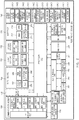
- an electronic device 301 may include a display 311, a metal sheet 312, a feeding circuit 313, a bracket 314, a circuit board 315, a battery 316, a housing 317, and a rear cover 318.
- the display 311 may correspond to the display 160 of FIG. 1 , the first display 260 of FIG. 2 , or the second display 265 of FIG. 2 .
- the display 311 may constitute at least part of the front surface of the electronic device 301.
- FIG. 4 the configuration of the display 311 will be described in detail.
- the metal sheet 312 may be coupled to the bottom surface of the display 311.
- the metal sheet 312 may block electromagnetic waves such that the electromagnetic waves generated by the operation of the display 311 do not affect the internal configuration of the electronic device 301 (e.g., the circuit board 315, or the like).
- the metal sheet 312 may be referred to as a "display ground”.
- the feeding circuit 313 may feed an antenna for wireless communication of the electronic device 301.
- a component such as an antenna radiator, an amplifier, an oscillator, a filter, or the like may be connected to the feeding circuit 313 or may be mounted in the feeding circuit 313.
- the metal sheet 312 may be referred to as a "feeding flexible printed circuit board (feeding FPCB)".
- the bracket 314 may physically support various components embedded in the electronic device 301.
- the circuit board 315 may include a main circuit board, a sub circuit board, and a connector electrically connecting between the main circuit board and the sub circuit board.
- the circuit board 315 may be implemented with a Printed Circuit Board (PCB), a FPCB, or the like. According to various embodiments, the circuit board 315 may be referred to as a "main board”.
- the battery 316 may convert chemical energy and electrical energy bidirectionally.
- the battery 316 may convert chemical energy into electrical energy to supply the converted electrical energy to the display 311, the feeding circuit 313, and/or various modules mounted in the circuit board 315.
- the battery 316 may convert electrical energy from the outside into chemical energy and store the converted chemical energy.
- the circuit board 315 may include a power management module for managing charging and discharging of the battery 316.
- the housing 317 may be formed of a plastic injection molding material, and/or a metal material. According to various embodiments, at least part of the housing 317 may be made of metal. For example, in the case where the side surface of the housing 317 is formed of metal, a so-called metal bezel may be implemented. According to various embodiments, at least part of the metallic portion of the housing 317 may be used as an antenna radiator.
- the rear cover 318 may be coupled to the rear surface (a surface opposite to a surface on which the display 311 is arranged) of the housing 317.
- the rear cover 318 may be formed of tempered glass, a plastic injection-molding material, and/or a metal material. According to an embodiment, the rear cover 318 may be integrated with the housing 317 or may be implemented to be removable by the user.
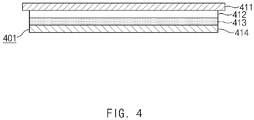
- FIG. 4 illustrates a sectional view of a display, according to an embodiment.
- the display 401 may include a cover glass 411, a touch panel 412, a display panel 413, and a pressure sensor 414.
- a cover glass 411 For example, at least one of the cover glass 411, the touch panel 412, the display panel 413, and the pressure sensor 414 may adhere to another component with optical clean adhesive (OCA).
- OCA optical clean adhesive
- Light generated by the display panel 413 may pass through the cover glass 411.
- a user may perform a touch input (including an input using an electronic pen) on the cover glass 411 by using a portion (e.g., a finger) of his/her body.
- the cover glass 411 may be formed of, for example, tempered glass, reinforced plastic, a flexible polymer material, or the like and may protect the display 401 or the electronic device equipped with the display 401 from an external shock.
- the touch panel 412 may receive a touch input from the user. For example, if a portion of user's body (e.g., a finger), a stylus (an example of an electronic pen), or the like contacts the touch panel 412, the touch input may be received by sensing the change in the amount of charge on the touch panel 412 (capacitive touch panel).
- the touch panel 412 may use at least one of resistive, infrared, and ultrasonic detecting methods, in addition to the capacitive method.
- the touch panel 412 may be referred to as various names, such as a touch screen panel (TSP), a touch sensor, or the like.
- the display panel 413 may output content (e.g., a text, an image, a video, an icon, a widget, a symbol, or the like).
- the display panel 413 may include a liquid crystal display (LCD) panel, a light-emitting diode (LED) display panel, an organic LED (OLED) display panel, a microelectromechanical systems (MEMS) display panel, or an electronic paper display panel.
- LCD liquid crystal display
- LED light-emitting diode
- OLED organic LED
- MEMS microelectromechanical systems
- the pressure sensor 414 may detect the pressure of the touch input of the user.
- the pressure sensor 414 may detect a pressure value of the touch input (including an input using an electronic pen) received from a portion (e.g., a finger) of the user's body.
- the pressure sensor 414 may detect the pressure of the touch input based on the capacitance changed depending on the touch input of a user (so-called, a capacitive pressure sensor). For another example, the pressure sensor 414 may detect the pressure of the touch input by recognizing a contact area where a user performs the touch input. Besides, the pressure sensor 414 may sense the pressure of the touch input in various manners. For example, the pressure sensor 414 may be implemented with a resistive pressure sensor, a piezo pressure sensor, or the like.
- the stacked structure of the display 401 illustrated in FIG. 4 is an example and is able to be variously modified.
- the touch panel 412 may be formed directly on a rear surface of the cover glass 411 (a so-called cover glass integrated touch panel), may be inserted between the cover glass 411 and the display panel 413 after being separately manufactured (a so-called add-on touch panel), may be formed directly on the display panel 413 (a so-called on-cell touch panel), or may be included inside the display panel 413 (a so-called in-cell touch panel).
- the pressure sensor 414 may be positioned in the same layer of the touch panel 412 or may be included inside the display panel 413.
- an embodiment is exemplified in FIG. 4 as the pressure sensor 414 is formed of one layer.
- the pressure sensor 414 may be implemented with a plurality of sensor modules and may be positioned on the rear surface of the display panel 413.
- FIG. 5 illustrates a block diagram of a program module, according to various embodiments.
- a program module 510 may include an operating system (OS) to control resources associated with an electronic device (e.g., the electronic device 101), and/or diverse applications (e.g., the application program 147) driven on the OS.
- OS operating system
- the OS may be, for example, AndroidTM, iOSTM, WindowsTM, SymbianTM, TizenTM, or BadaTM.
- the program module 510 may include a kernel 520, a middleware 530, an application programming interface (API) 560, and/or an application 570. At least a portion of the program module 510 may be preloaded on an electronic device or may be downloadable from an external electronic device (e.g., the electronic device 102 or 104, the server 106, or the like).
- API application programming interface
- the kernel 520 may include, for example, a system resource manager 521, or a device driver 523.
- the system resource manager 521 may perform control, allocation, or retrieval of system resources.
- the system resource manager 521 may include a process managing part, a memory managing part, or a file system managing part.
- the device driver 523 may include, for example, a display driver, a camera driver, a Bluetooth driver, a common memory driver, a USB driver, a keypad driver, a Wi-Fi driver, an audio driver, or an inter-process communication (IPC) driver.
- the display driver may control at least one or more DDIs (e.g., the first DDI 264 and the second DDI 268 of FIG. 2 ).
- the display driver may perform functions to control the DDI in response to the request of the application 570.
- the middleware 530 may provide, for example, a function that the application 570 needs in common, or may provide diverse functions to the application 570 through the API 560 to allow the application 570 to efficiently use limited system resources of the electronic device.
- the middleware 530 e.g., the middleware 143 may include at least one of a runtime library 535, an application manager 541, a window manager 542, a multimedia manager 543, a resource manager 544, a power manager 545, a database manager 546, a package manager 547, a connectivity manager 548, a notification manager 549, a location manager 550, a graphic manager 551, a security manager 552, or a payment manager 554.
- the runtime library 535 may include, for example, a library module that is used by a compiler to add a new function through a programming language while the application 570 is being executed.
- the runtime library 535 may perform input/output management, memory management, or capacities about arithmetic functions.
- the application manager 541 may manage, for example, a life cycle of at least one application of the application 570.
- the window manager 542 may manage a GUI resource which is used in a screen. For example, in the case where the electronic device includes a plurality of displays (e.g., the first display 260 and the second display 265 of FIG. 2 ), the window manager 542 may independently manage the screen (e.g., the output ratio of the screen) of each display, depending on the operation of the application 570.
- the multimedia manager 543 may identify a format necessary to play diverse media files, and may perform encoding or decoding of media files by using a codec suitable for the format.
- the resource manager 544 may manage resources such as a storage space, memory, or source code of at least one application of the application 570.
- the power manager 545 may operate, for example, with a basic input/output system (BIOS) to manage a battery or power, and may provide power information for an operation of an electronic device.
- the database manager 546 may generate, search for, or modify database that is to be used in at least one application of the application 570.
- the package manager 547 may install or update an application that is distributed in the form of package file.
- the connectivity manager 548 may manage, for example, wireless connection such as Wi-Fi or Bluetooth.
- the notification manager 549 may display or notify an event such as arrival message, appointment, or proximity notification in a mode that does not disturb a user.
- the location manager 550 may manage location information about an electronic device.
- the graphic manager 551 may manage a graphic effect that is provided to a user, or manage a user interface relevant thereto.
- the security manager 552 may provide a general security function necessary for system security, user authentication, or the like.
- the middleware 530 may further include a telephony manager for managing a voice or video call function of the electronic device.
- the middleware 530 may include a middleware module that combines diverse functions of the above-described components.
- the middleware 530 may provide a module specialized to each OS kind to provide differentiated functions. Additionally, the middleware 530 may dynamically remove a part of the preexisting components or may add new components thereto.
- the API 560 may be, for example, a set of programming functions and may be provided with a configuration that is variable depending on an OS. For example, in the case where an OS is AndroidTM or iOSTM, it may provide one API set per platform. In the case where an OS is TizenTM, it may provide two or more API sets per platform.
- the application 570 may include, for example, one or more applications capable of providing functions for a home 571, a dialer 572, an SMS/MMS 573, an instant message (IM) 574, a browser 575, a camera 576, an alarm 577, a contact 578, a voice dial 579, an e-mail 580, a calendar 581, a media player 582, an album 583, a timepiece 584, and a payment 585 or for offering health care (e.g., measuring an exercise quantity, blood sugar, or the like) or environment information (e.g., information of barometric pressure, humidity, temperature, or the like).
- health care e.g., measuring an exercise quantity, blood sugar, or the like
- environment information e.g., information of barometric pressure, humidity, temperature, or the like.
- the application 570 may include an application (hereinafter referred to as "information exchanging application” for descriptive convenience) to support information exchange between an electronic device (e.g., the electronic device 101) and an external electronic device (e.g., the electronic device 102 or 104).
- the information exchanging application may include, for example, a notification relay application for transmitting specific information to an external electronic device, or a device management application for managing the external electronic device.
- the notification relay application may include a function of transmitting notification information, which arise from other applications (e.g., applications for SMS/MMS, e-mail, health care, or environmental information), to an external electronic device (e.g., the electronic device 102 or 104). Additionally, the notification relay application may receive, for example, notification information from an external electronic device and provide the notification information to a user.
- applications e.g., applications for SMS/MMS, e-mail, health care, or environmental information
- an external electronic device e.g., the electronic device 102 or 104
- the notification relay application may receive, for example, notification information from an external electronic device and provide the notification information to a user.
- the device management application may manage (e.g., install, delete, or update), for example, at least one function (e.g., turn-on/turn-off of an external electronic device (e.g., the electronic device 102 or 104) itself (or a part) or adjustment of brightness (or resolution) of a display) of the external electronic device which communicates with the electronic device, an application running in the external electronic device, or a service (e.g., a call service, a message service, or the like) provided from the external electronic device.
- at least one function e.g., turn-on/turn-off of an external electronic device (e.g., the electronic device 102 or 104) itself (or a part) or adjustment of brightness (or resolution) of a display) of the external electronic device which communicates with the electronic device, an application running in the external electronic device, or a service (e.g., a call service, a message service, or the like) provided from the external electronic device.
- a service e.g.,
- the application 570 may include an application (e.g., a health care application of a mobile medical device) that is assigned in accordance with an attribute of an external electronic device (e.g., the electronic device 102 or 104).
- the application 570 may include an application that is received from an external electronic device (e.g., the electronic device 102 or 104, or the server 106).
- the application 570 may include a preloaded application or a third party application that is downloadable from a server.
- the names of components of the program module 510 according to the embodiment may be modifiable depending on kinds of operating systems.
- At least a portion of the program module 510 may be implemented by software, firmware, hardware, or a combination of two or more thereof. At least a portion of the program module 510 may be implemented (e.g., executed), for example, by the processor (e.g., the processor 210). At least a portion of the program module 510 may include, for example, modules, programs, routines, sets of instructions, processes, or the like for performing one or more functions.
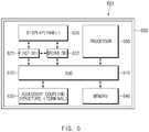
- FIG. 6 is a block diagram illustrating an electronic device, according to an embodiment of the present disclosure.
- an electronic device 601 may include a bus 610, a display (panel) 620, a first DDI 621 and a second DDI 622, an accessory coupling structure (terminal) 630, a memory 640, a processor 650, and a housing 660.
- the electronic device 601 may not include at least one of the above-described elements or may further include any other element(s) (refer to FIGS. 1 to 5 ).
- the bus 610 (corresponding to the bus 110 of FIG. 1 ) may connect the components included in the electronic device 601 to each other and may include a circuit conveying communication among components.
- the display (panel) 620 (e.g., corresponding to the display 160 of FIG. 1 , the display 260 or 265 of FIG. 2 , or the display 401 of FIG. 4 ) may display content (e.g., a text, an image, a video, an icon, a symbol, or the like) under control of the processor 650.
- the display 620 may include pixels, which are arranged in a plurality of rows and a plurality of columns, based on the set resolution.
- the display 620 may include a touch panel for receiving the user's touch input and a pressure sensor for detecting the pressure of the touch input (refer to FIG. 4 ).
- FIG. 7 illustrates a display of an electronic device, according to an embodiment.
- the front surface of the electronic device 701 may include a display 720 and a housing 760.
- the housing 760 may be coupled to the display 720.
- the front surface of the housing 760 may be referred to as a "bezel" in that the housing 760 surrounds the display 720 in the front surface of the electronic device 701.
- the display 720 may be divided into a main area 720-m and edge areas 720-u, 720-b, 720-1, and 720-r, in a content output area (or screen).
- the edge area may correspond to an area having a specified width toward the inside of the display 720 from the outer boundary of the display 720.
- the edge area may include the upper side edge area 720-u, the bottom side edge area 720-b, the left side edge area 720-1, and the right side edge area 720-r, depending on the positioned portion.
- the graphic effect according to various embodiments of the present disclosure may be applied to the edge areas 720-u, 720-b, 720-1, and 720-r.
- the first DDI 621 and the second DDI 622 may drive the display 620.
- the first DDI 621 and the second DDI 622 may correspond to the first DDI 264 and the second DDI 268 illustrated in FIG. 2 , respectively.
- an electronic device may include a single DDI.
- the first DDI 621 and the second DDI 622 may supply the display 620 with an image signal corresponding to image data received from the processor 650 (a host) at the preset frame rate.
- the first DDI 621 and the second DDI 622 may include a graphics RAM, an interface module, an image processing unit, a multiplexer, a display timing controller (T-con), a source driver, a gate driver, an oscillator, or the like.
- each of the first DDI 621 and the second DDI 622 may perform graphic processing on an image to be displayed in the main area (e.g., 720-m of FIG. 7 ) of the display 620 and an image to be displayed in an edge area (e.g., the edge area 720-u, 720-b, 720-1, or 720-r of FIG. 7 ), under control of the processor 650.
- the main area e.g., 720-m of FIG. 7
- an edge area e.g., the edge area 720-u, 720-b, 720-1, or 720-r of FIG. 7
- the second DDI 622 may be dependent on the first DDI 621.
- the first DDI 621 may perform graphic processing on the main area based on the received graphic data and may transmit the processed result to the second DDI 622.
- the second DDI 622 may perform graphic processing on an image to be displayed in the edge area, based on the data received from the first DDI 621.
- the accessory coupling structure (terminal) 630 may provide an interface that allows an external accessory to be physically or electrically coupled to the electronic device 601. According to an embodiment, it is understood that the accessory coupling structure 630 includes the input/output interface 150 of FIG. 1 .
- the processor 650 may determine whether the external accessory is detachable, the type of the external accessory, the color of the external accessory, or the like by transmitting or receiving a specified signal to or from the external accessory through the accessory coupling structure 630.
- the external accessory may include various members capable of being mounted in or connected to the electronic device 601.
- the external accessory may include a case capable of surrounding at least part of the exterior appearance of the electronic device 601.
- the external accessory in the case where the electronic device 601 is implemented with a smart watch, may include a band (or fob) capable of being coupled to the smart watch.
- the memory 640 may store commands or data associated with operations of components included in the electronic device 601. For example, when executed, the memory 640 may store instructions that cause the processor 650 to perform various operations described in the present disclosure. According to an embodiment, the memory 640 may store color information of the housing 660.
- the processor 650 may be operatively connected to components included in the electronic device 601 through the bus 610 and may execute operations or data processing associated with control and/or communication of the components included in the electronic device 601.
- the processor 650 may obtain information about an exterior color and may extract a dominant color from a specified area in the content display area (or screen) of the display 620.
- the processor 650 may apply a gradation effect for transitioning from the exterior color to the dominant color, to at least part (e.g., at least one of the upper side edge area and the bottom side edge area) of the edge area of the display 620.
- the processor 650 may read information about the color of the housing 660 from the memory 640 and may obtain the information about the color of the housing 660 as information about the exterior color. According to another embodiment, the processor 650 may obtain information about the color of the external accessory as information about the exterior color, by transmitting or receiving a specified signal to or from the external accessory through the accessory coupling structure 630.
- the processor 650 may calculate a ratio of pixels, displaying a color having the highest occupancy, to a plurality of pixels constituting the specified area and may determine the corresponding color as a dominant color.
- the specified area may be composed of pixels arranged in a plurality of rows and a plurality of columns.
- the processor 650 may extract the dominant color for each of the plurality of columns and may apply the gradation effect based on the extracted plurality of dominant color.
- the processor 650 may extract the dominant color again from the specified area. Accordingly, the dominant color for applying the gradation effect may be updated. That is, the processor 650 may adaptively apply the gradation effect to the edge area.
- the processor 650 may adjust the weight of the exterior color or the dominant color in the gradation effect, depending on the user input. For example, in the case where the scrolling (an example of a user input) for changing an area, in which content is displayed, to a specified direction is received, the processor 650 may increase or decrease the ratio of the dominant color in the gradation effect, depending on the speed of the user input. For another example, in the case where a touch input (so-called, 'force touch') (an example of a user input) having a specific pressure is received through the display 620, the processor 650 may increase or decrease the ratio of the dominant color in the gradation effect, depending on the pressure of the touch input.
- a touch input so-called, 'force touch'
- the processor 650 may be configured to apply the gradation effect. For example, in the case where the aspect ratio of content to be displayed on the display 620 does not coincide with the aspect ratio the display 620, the processor 650 may apply the gradation effect. In the case where the resolution of the content to be displayed on the display 620 is 640 ⁇ 480 and the resolution of the display 620 is 1920 ⁇ 1080, since the aspect ratio of the content is 4:3 and aspect ratio of the display 620 is 16:9, the processor 650 may apply the gradation effect to the edge area.
- the processor 650 may control graphic outputs associated with the main area (e.g., 720-m of FIG. 7 ) in which the content is displayed and the edge area (e.g., the edge areas 720-u, 720-b, 720-1, and 720-r of FIG. 7 ) to which the gradation effect is applied, through different DDIs.
- the processor 650 may control the graphic output of the edge area through at least one (e.g., the first DDI 621) of a plurality of DDIs and may control the graphic output of the main area through a DDI (e.g., the second DDI 622) different from the DDI of the at least one.
- processor 650 The above-described operations of the processor 650 are, but are not limited to, an example. For example, it is understood that the operation of a "processor” written in another portion of the present disclosure is the operation of the processor 650. In addition, it is understood that at least part of operations written as the operation of the "electronic device” is the operation of the processor 650.
- the housing 660 may protect various components in the electronic device 601 from an external shock or dust.
- the housing 660 may be formed of a plastic injection molding material and/or a metal material.
- the housing 660 may constitute at least part of the external appearance of the electronic device 601 and may be physically coupled to the display 620.
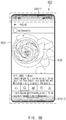
- FIG. 8 is a view for describing a method of applying a graphic effect, according to an embodiment.
- the front surface of an electronic device 801 is illustrated.
- the front surface of the electronic device 801 may include a display 810 and a housing 860 surrounding the display.
- the processor of the electronic device 801 may read information about the color of the housing 860 (or bezel) from the memory of the electronic device 801 and may obtain information about the color of the housing 860 as information about an exterior color.
- the processor of the electronic device 801 may extract a dominant color from a specified area 830 in the content display area (or screen) of the display 810.
- the processor of the electronic device 801 may apply a gradation effect for transitioning from the exterior color (i.e., the color of the housing 860) to the dominant color, to an upper side edge area 820 of the display 810.
- the color transition of the exterior color may start from the boundary between the housing 860 and the display 810
- the dominant color may start the color transition from the boundary 831 between the upper side edge area 820 and the specified area 830.
- FIGS. 9A and 9B are other views for describing a method of applying a graphic effect, according to an embodiment.
- the front surface of an electronic device 901 may be composed of a display 910 and a housing 961 (or bezel).
- the processor of the electronic device 901 may apply a gradation effect to an upper side edge area 920 in the manner described in FIG. 7 and/or 8.
- the user of the electronic device 901 may not be aware of the upper side boundary between the housing 961 (or bezel) and the display 910 due to the gradation effect.
- the electronic device 901 may achieve the effect that the content display area (or screen) of the display 910 extends to the upper side of the housing 961.
- the front surface of an electronic device 902 may be composed of a display 930 and a housing 962 (or bezel).
- the processor of the electronic device 902 may apply the gradation effect, which is described in FIG. 7 and/or 8, to an upper side edge area 940-1 and a bottom side edge area 940-2.
- the user of the electronic device 902 may not be aware of the upper/bottom side boundary between the housing 962 (or bezel) and the display 930 due to the gradation effect. As such, the electronic device 902 may achieve the effect that the content display area (or screen) of the display 930 extends to the upper/bottom side of the housing 962.
- FIG. 10 is a view for describing a method of applying a graphic effect based on a user input.
- a graphic effect applying method based on a user input may be performed in electronic devices 1001 and 1002.
- the electronic devices 1001 and 1002 may adjust the weight of a color used to a gradation effect, depending on the user input.
- the gradation effect for transitioning from the color of a housing 1061 to the pre-extracted color may be applied to an upper side edge area 1010 of the electronic device 1001.
- a user may scroll (an example of a user input) the electronic device 1001 in a bottom side direction 1011.
- the display area of content on a display may move in the bottom side direction 1011.
- the electronic device 1001 may increase the weight, at which the color of the housing 1061 is occupied, in the gradation effect (decrease the weight at which the pre-extracted color is occupied).
- the gradation effect for transitioning from the color of a housing 1062 to the pre-extracted color may be applied to an upper side edge area 1020 of the electronic device 1002.
- the user may scroll the electronic device 1002 in an upper side direction 1021.
- the display area of content on a display may move in the upper side direction 1021.
- the electronic device 1002 may decrease the weight, at which the color of the housing 1062 is occupied, in the gradation effect (increase the weight at which the pre-extracted color is occupied).
- the user input may include a touch input (so-called, 'force touch') having a specific pressure.
- a touch input so-called, 'force touch'
- an electronic device may adjust the weight of a color used for the gradation effect based on the pressure of the force input.
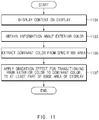
- FIG. 11 is a flowchart of a method of applying a graphic effect, according to an embodiment.
- a graphic effect applying method may include operation 1101 to operation 1107.
- operation 1101 to operation 1107 may be performed by the electronic device 601 of FIG. 6 .
- Operation 1101 to operation 1107 may be respectively implemented with, for example, instructions that are capable of being performed (or executed) by the processor 650 of the electronic device 601.
- the instructions may be stored in, for example, a computer-readable recording medium or the memory 640 of the electronic device 601 illustrated in FIG. 6 .
- operation 1101 to operation 1107 will be described by using the reference numerals of FIG. 6 .
- the processor 650 of the electronic device 601 may display content on the display 620.
- the processor 650 of the electronic device 601 may obtain information about an exterior color.
- the processor 650 may obtain information about the color of the housing 660 from the memory 640 or may obtain information about the color of an external accessory from the external accessory through the accessory coupling structure 630.
- the processor 650 of the electronic device 601 may extract a dominant color from a specified area of an area in which content is displayed, in the display 620.
- the dominant color may include a plurality of colors.
- the processor 650 may extract the dominant color for each of the plurality of columns.
- the processor 650 of the electronic device 601 may apply a gradation effect for transitioning from an exterior color obtained in operation 1103 to the dominant color extracted in operation 1105, to at least part of the edge area of the display 620.
- FIG. 12 is a flowchart of a method of applying a graphic effect, according to another embodiment.
- a graphic effect applying method may include operation 1201 to operation 1211.
- Operation 1201 to operation 1211 may be performed by, for example, the electronic device 601 illustrated in FIG. 6 .
- Operation 1201 to operation 1211 may be respectively implemented with, for example, instructions that are capable of being performed (or executed) by the processor 650 of the electronic device 601.
- the instructions may be stored in, for example, a computer-readable recording medium or the memory 640 of the electronic device 601 illustrated in FIG. 6 .
- the reference numeral of FIG. 6 may be used in a description of FIG. 12 , and a description that is the same as described with reference to FIG. 11 may not be repeated here.
- the processor 650 of the electronic device 601 may display content on the display 620.
- the processor 650 of the electronic device 601 may determine whether a specified condition is satisfied.
- the specified condition may correspond to whether the aspect ratio of content to be displayed on the display 620 coincides with the aspect ratio of the display 620.
- the procedure may proceed to operation 1205.
- the processor 650 of the electronic device 601 may end the process (i.e., the gradation effect may not be applied).
- the processor 650 of the electronic device 601 may obtain information about an exterior color.
- the processor 650 of the electronic device 601 may extract a dominant color from a specified area of an area in which content is displayed, in the display 620.
- the processor 650 of the electronic device 601 may apply a gradation effect for transitioning from an exterior color obtained in operation 1205 to the dominant color extracted in operation 1207, to at least part of the edge area of the display 620.
- the processor 650 of the electronic device 601 may determine whether the content included in the specified area is changed depending on a user input (e.g., scrolling, or the like). For example, in the case where the processor 650 determines that the content included in the specified area is changed in response to the user input, the processor 650 may return to operation 1207 and then may update the dominant color. In the case where the processor 650 determines that the content included in the specified area is not changed, the processor 650 may terminate the process (i.e., may maintain the existing gradation effect).
- the user input may include a scrolling input for changing the display area of the content in a specified direction, or a touch input ('force touch') of a specified pressure or more.
- the processor 650 may increase or decrease the occupancy rate of a dominant color (or exterior color) in the gradation effect, based on the speed of the scrolling input or the pressure of the force touch.
- an electronic device may provide an optical illusion effect that a display extends toward the outside of the bezel, by applying the gradation effect to the edge area of the display.
- the exterior color used for the gradation effect may be changed depending on the color of the coupled external accessory (e.g., a case, a band, or the like) as well as the color of the housing of the electronic device.
- the electronic device may provide a more integrated design language between the display and the external accessory.
- an electronic device may include a display displaying content and a processor operatively connected to the display.
- the processor may be configured to obtain information about an exterior color, to extract a dominant color from a specified area among an area in which the content is displayed, and to apply a gradation effect for transitioning from the exterior color to the dominant color, to at least part of an edge area of the display.
- the edge area may correspond to an area having a specified width toward an inside of the display from an outer boundary of the display.
- the edge area may include an upper side edge area, a bottom side edge area, a left side edge area, and a right side edge area.
- the processor may be configured to apply the gradation effect to at least one of the upper side edge area and the bottom side edge area.
- the electronic device may further include a housing constituting at least part of an external appearance of the electronic device, wherein the housing is coupled to the display; the processor may be configured to obtain information about a color of the housing as information about the exterior color.
- the electronic device may further include a structure that allows an external accessory to be physically or electrically coupled to the electronic device.
- the processor may be configured to obtain information about a color of the external accessory as information about the exterior color.
- the external accessory may include a case surrounding at least part of an external appearance of the electronic device.
- the processor when a specified condition is satisfied, the processor is configured to apply the gradation effect.
- the processor when an aspect ratio of the content to be displayed on the display does not coincide with an aspect ratio of the display, the processor may be configured to apply the gradation effect.
- the electronic device may further include a plurality of display driving integrated-circuits (DDIs) for driving the display.
- the processor may be configured to control a graphic output of the edge area through at least one of the plurality of DDIs and to control a graphic output of an area, in which the content is displayed, through another DDI different from the at least one DDI.
- the processor when the content included in the specified area is changed depending on a user input, the processor may be configured to update the dominant color.
- the user input may correspond to scrolling for changing an area, in which the content is displayed, in a specified direction
- the processor may be configured to increase or decrease a ratio of the dominant color in the gradation effect, depending on a speed of the scrolling.
- the display may further include a touch panel for receiving a touch input and a pressure sensor for detecting a pressure of the touch input.
- the processor may be configured to increase or decrease an occupancy ratio of the dominant color in the gradation effect, depending on the pressure of the touch input.
- the specified area may be composed of pixels arranged in a plurality of rows and a plurality of columns.
- the processor may be configured to extract the dominant color for each of the plurality of columns and to apply the gradation effect based on the extracted plurality of dominant colors.
- the graphic effect applying method may include displaying content on a display, obtaining information about an exterior color, extracting a dominant color from a specified area among an area in which the content is displayed, and applying a gradation effect for transitioning from the exterior color to the dominant color, to at least part of an edge area of the display.
- the obtaining of the information about the exterior color may include obtaining information about a color of a housing forming an appearance of the electronic device.
- the obtaining of the information about the exterior color may include obtaining information about a color of an external accessory coupled to the electronic device.
- applying the gradation effect may be performed when a specified condition is satisfied.
- the specified condition may include the case where an aspect ratio of the content to be displayed on the display does not coincide with an aspect ratio of the display.
- the graphic effect applying method may further include updating the dominant color when the content included in the specified area is changed depending on a user input.
- the user input may correspond to scrolling for changing an area, in which the content is displayed, in a specified direction.
- the graphic effect applying method may further include increasing or decreasing a ratio of the dominant color in the gradation effect, depending on a speed of the scrolling.
- module used in the present disclosure may represent, for example, a unit including one or more combinations of hardware, software and firmware.
- the term “module” may be interchangeably used with the terms “unit”, “logic”, “logical block”, “part” and “circuit”.
- the “module” may be a minimum unit of an integrated part or may be a part thereof.
- the “module” may be a minimum unit for performing one or more functions or a part thereof.
- the “module” may be implemented mechanically or electronically.
- the “module” may include at least one of an application-specific IC (ASIC) chip, a field-programmable gate array (FPGA), and a programmable-logic device for performing some operations, which are known or will be developed.
- ASIC application-specific IC
- FPGA field-programmable gate array
- At least a part of an apparatus (e.g., modules or functions thereof) or a method (e.g., operations) may be, for example, implemented by instructions stored in a computer-readable storage media in the form of a program module.
- the instruction when executed by a processor (e.g., the processor 120), may cause the one or more processors to perform a function corresponding to the instruction.
- the computer-readable storage media for example, may be the memory 130.
- a computer-readable recording medium may include a hard disk, a floppy disk, a magnetic media (e.g., a magnetic tape), an optical media (e.g., a compact disc read only memory (CD-ROM) and a digital versatile disc (DVD), a magneto-optical media (e.g., a floptical disk)), and hardware devices (e.g., a read only memory (ROM), a random access memory (RAM), or a flash memory).
- the one or more instructions may contain a code made by a compiler or a code executable by an interpreter.
- the above hardware unit may be configured to operate via one or more software modules for performing an operation according to various embodiments, and vice versa.
Landscapes
- Engineering & Computer Science (AREA)
- Theoretical Computer Science (AREA)
- General Engineering & Computer Science (AREA)
- Physics & Mathematics (AREA)
- General Physics & Mathematics (AREA)
- Human Computer Interaction (AREA)
- Computer Hardware Design (AREA)
- Computer Vision & Pattern Recognition (AREA)
- User Interface Of Digital Computer (AREA)
Description
- The present disclosure relates to a method of applying a graphic effect to a display and an electronic device performing the same.
- Various types of electronic devices, such as a smartphone, a wearable device, and the like have been widely distributed since the spread of a personal computer (PC). Various types of user interfaces (UIs) have been applied to the electronic devices to interact with a user.
- For example, an electronic device may include a touch display capable of operating an input means for receiving an input from the user, as well as a visual display means. The user may easily and intuitively enter a user input through a graphic user interface (GUI), which is implemented through the touch display. Document
US2007/242162 relates to a method and system to provide an optical illusion in respect of ambient light external to the display to extend the display. - Embodiments disclosed in the present disclosure may relate to a method of applying a graphic effect, and may provide a method of adaptively applying a specified graphic effect (e.g., gradation effect) to an edge area of the display of an electronic device and an electronic device performing the same.
- According to an embodiment disclosed the present disclosure, an electronic device may include a display displaying content and a processor operatively connected to the display. The processor may be configured to obtain information about an exterior color, to extract a dominant color from a specified area in an area in which the content is displayed, and to apply a gradation effect for transitioning from the exterior color to the dominant color, to at least part of an edge area of the display.
- In addition, according to an embodiment disclosed the present disclosure, a graphic effect applying method of an electronic device may include displaying content on a display, obtaining information about an exterior color, extracting a dominant color from a specified area in an area in which the content is displayed, and applying a gradation effect for transitioning from the exterior color to the dominant color, to at least part of an edge area of the display.
- Other aspects, advantages, and salient features of the disclosure will become apparent to those skilled in the art from the following detailed description, which, taken in conjunction with the annexed drawings, discloses various embodiments of the present disclosure.
- According to an embodiment disclosed in the present disclosure, an electronic device may provide a more integrated design language between a display and housing by applying a gradation effect to the edge area of the display. Furthermore, an optical illusion effect that the display extends toward the outside of the bezel (a part of the housing) may be provided. Besides, a variety of effects directly or indirectly understood through the present disclosure may be provided. The invention will be carried out according to the attached independent claims.
-
-
FIG. 1 illustrates an electronic device in a network environment, according to various embodiments. -
FIG. 2 illustrates a block diagram of the electronic device, according to various embodiments. -
FIG. 3 illustrates an internal configuration of an electronic device, according to an embodiment. -
FIG. 4 illustrates a sectional view of a display, according to an embodiment. -
FIG. 5 is a block diagram of a program module according to various embodiments. -
FIG. 6 is a block diagram illustrating an electronic device, according to an embodiment of the present disclosure. -
FIG. 7 illustrates a display of an electronic device, according to an embodiment. -
FIG. 8 is a view for describing a method of applying a graphic effect, according to an embodiment. -
FIGS. 9A and9B are other views for describing a method of applying a graphic effect, according to an embodiment. -
FIG. 10 is a view for describing a method of applying a graphic effect based on a user input. -
FIG. 11 is a flowchart of a method of applying a graphic effect, according to an embodiment. -
FIG. 12 is a flowchart of a method of applying a graphic effect, according to another embodiment. -
FIG. 1 illustrates an electronic device in a network environment system, according to various embodiments. - Referring to
FIG. 1 , according to various embodiments, anelectronic device server 106 may be connected each other over anetwork 162 or ashort range communication 164. Theelectronic device 101 may include abus 110, aprocessor 120, amemory 130, an input/output interface 150, adisplay 160, and acommunication circuit 170. According to an embodiment, theelectronic device 101 may not include at least one of the above-described components or may further include other component(s). - For example, the
bus 110 may interconnect the above-describedcomponents 110 to 170 and may include a circuit for conveying communications (e.g., a control message and/or data) among the above-described components. - The
processor 120 may include one or more of a central processing unit (CPU), an application processor (AP), or a communication processor (CP). For example, theprocessor 120 may be operatively connected toother components 110 to 170 so as to perform an arithmetic operation or data processing associated with control and/or communication of at least other components of theelectronic device 101. - The
memory 130 may include a volatile and/or nonvolatile memory. For example, thememory 130 may store commands or data associated with at least one other component(s) of theelectronic device 101. - According to an embodiment, the
memory 130 may store software and/or aprogram 140. Theprogram 140 may include, for example, akernel 141, amiddleware 143, an application programming interface (API) 145, and/or an application program (or "an application") 147. At least a part of thekernel 141, themiddleware 143, or theAPI 145 may be referred to as an "operating system (OS)". - For example, the
kernel 141 may control or manage system resources (e.g., thebus 110, theprocessor 120, thememory 130, and the like) that are used to execute operations or functions of other programs (e.g., themiddleware 143, theAPI 145, and the application program 147). Furthermore, thekernel 141 may provide an interface that allows themiddleware 143, theAPI 145, or theapplication program 147 to access discrete components of theelectronic device 101 so as to control or manage system resources. - The
middleware 143 may perform, for example, a mediation role such that theAPI 145 or theapplication program 147 communicates with thekernel 141 to exchange data. - Furthermore, the
middleware 143 may process task requests received from theapplication program 147 according to a priority. For example, themiddleware 143 may assign the priority, which makes it possible to use a system resource (e.g., thebus 110, theprocessor 120, thememory 130, or the like) of theelectronic device 101, to at least one of theapplication program 147. For example, themiddleware 143 may process the one or more task requests according to the priority assigned to the at least one, which makes it possible to perform scheduling or load balancing on the one or more task requests. - The API 145 may be, for example, an interface through which the
application program 147 controls a function provided by thekernel 141 or themiddleware 143, and may include, for example, at least one interface or function (e.g., an instruction) for a file control, a window control, image processing, a character control, or the like. - The input/
output interface 150 may play a role, for example, of an interface which transmits a command or data input from a user or another external device, to other component(s) of theelectronic device 101. Furthermore, the input/output interface 150 may output a command or data, received from other component(s) of theelectronic device 101, to a user or another external device. - The
display 160 may display, for example, various pieces of content (e.g., a text, an image, a video, an icon, a symbol, and the like) to a user. In thedisplay 160, an area in which a user is capable of visually recognizing may be referred to a "content display area or screen". The content display area of thedisplay 160 may form a single area or may be logically divided into a plurality of areas. For example, the content display area of thedisplay 160 may be divided into two areas. In this case, the first area and the second area may display, for example, different pieces of content. For another example, the first area may continuously display a part of content being displayed in the second area (i.e., the first area and the second area may be regarded as one area). - According to an embodiment, the
display 160 may include a touch panel capable of receiving the touch input of a user, and/or a pressure sensor capable of detecting the pressure of the touch input. For example, thedisplay 630 may obtain a touch, gesture, proximity, or hovering input using an electronic pen or a part of the user's body (e.g., finger). - The
display 160 may include, for example, a liquid crystal display (LCD), a light-emitting diode (LED) display, an organic LED (OLED) display, a microelectromechanical systems (MEMS) display, or an electronic paper display. The configuration and the function operation ofdisplay 160 will be described with reference toFIGS. 2 to 4 . - For example, the
communication circuit 170 may establish communication between theelectronic device 101 and an external device (e.g., the first externalelectronic device 102, the second externalelectronic device 104, or the server 106). For example, thecommunication circuit 170 may be connected to thenetwork 162 over wireless communication or wired communication to communicate with the external device (e.g., the second externalelectronic device 104 or the server 106). - The wireless communication may include cellular communication using at least one of, for example, long-term evolution (LTE), LTE Advanced (LTE-A), Code Division Multiple Access (CDMA), Wideband CDMA (WCDMA), Universal Mobile Telecommunications System (UMTS), Wireless Broadband (WiBro), Global System for Mobile Communications (GSM), or the like, as cellular communication protocol. According to an embodiment, the wireless communication may include, for example, the
short range communication 164. Theshort range communication 164 may include at least one of wireless fidelity (Wi-Fi), Bluetooth, Bluetooth low energy (BLE), near field communication (NFC), magnetic secure transmission (MST), radio frequency (RF), a body area network (BAN), or a global navigation satellite system (GNSS), or the like. - The MST may generate a pulse in response to transmission data using an electromagnetic signal, and the pulse may generate a magnetic field signal. The
electronic device 101 may transfer the magnetic field signal to point of sale (POS), and the POS may detect the magnetic field signal using a MST reader. The POS may recover the data by converting the detected magnetic field signal to an electrical signal. - The GNSS may include at least one of, for example, a global positioning system (GPS), a global navigation satellite system (Glonass), a Beidou navigation satellite system (hereinafter referred to as "Beidou"), or an European global satellite-based navigation system (hereinafter referred to as "Galileo") based on an available region, a bandwidth, or the like. Hereinafter, in the present disclosure, "GPS" and "GNSS" may be interchangeably used.
- The wired communication may include at least one of, for example, a universal serial bus (USB), a high definition multimedia interface (HDMI), a recommended standard-232 (RS-232), a plain old telephone service (POTS), or the like. The
network 162 may include at least one of telecommunications networks, for example, a computer network (e.g., LAN or WAN), an Internet, or a telephone network. - Each of the first and second external
electronic devices electronic device 101. According to an embodiment, theserver 106 may include a group of one or more servers. According to various embodiments, all or a portion of operations that theelectronic device 101 will perform may be executed by another or plural electronic devices (e.g., theelectronic device electronic device 101 executes any function or service automatically or in response to a request, theelectronic device 101 may not perform the function or the service internally, but, alternatively additionally, it may request at least a portion of a function associated with theelectronic device 101 from another device (e.g., theelectronic device electronic device electronic device 101. Theelectronic device 101 may provide the requested function or service using the received result or may additionally process the received result to provide the requested function or service. To this end, for example, cloud computing, distributed computing, or client-server computing may be used. -
FIG. 2 illustrates a block diagram of an electronic device, according to an embodiment. - Referring to
FIG. 2 , anelectronic device 201 may include, for example, all or a part of theelectronic device 101 illustrated inFIG. 1 . Theelectronic device 201 may include one or more processors (e.g., an application processor (AP)) 210, acommunication module 220, asubscriber identification module 229, amemory 230, asensor module 240, aninput device 250, adisplay 260, aninterface 270, anaudio module 280, acamera module 291, apower management module 295, abattery 296, anindicator 297, and amotor 298. - The
processor 210 may drive, for example, an operating system (OS) or an application to control a plurality of hardware or software components connected to theprocessor 210 and may process and compute a variety of data. For example, theprocessor 210 may be implemented with a System on Chip (SoC). According to an embodiment, theprocessor 210 may further include a graphic processing unit (GPU) and/or an image signal processor. Theprocessor 210 may include at least a part (e.g., a cellular module 221) of components illustrated inFIG. 2 . Theprocessor 210 may load a command or data, which is received from at least one of other components (e.g., a nonvolatile memory), into a volatile memory and process the loaded command or data. Theprocessor 210 may store a variety of data in the nonvolatile memory. - The
communication module 220 may be configured the same as or similar to thecommunication circuit 170 ofFIG. 1 . Thecommunication module 220 may include thecellular module 221, a Wi-Fi module 222, a Bluetooth (BT)module 223, a GNSS module 224 (e.g., a GPS module, a Glonass module, a Beidou module, or a Galileo module), a near field communication (NFC)module 225, aMST module 226 and a radio frequency (RF)module 227. - The
cellular module 221 may provide, for example, voice communication, video communication, a character service, an Internet service, or the like over a communication network. According to an embodiment, thecellular module 221 may perform discrimination and authentication of theelectronic device 201 within a communication network by using the subscriber identification module (e.g., a SIM card) 229. According to an embodiment, thecellular module 221 may perform at least a portion of functions that theprocessor 210 provides. According to an embodiment, thecellular module 221 may include a communication processor (CP). - Each of the Wi-
Fi module 222, theBT module 223, theGNSS module 224, theNFC module 225, or theMST module 226 may include a processor for processing data exchanged through a corresponding module, for example. According to an embodiment, at least a part (e.g., two or more) of thecellular module 221, the Wi-Fi module 222, theBT module 223, theGNSS module 224, theNFC module 225, or theMST module 226 may be included within one Integrated Circuit (IC) or an IC package. - For example, the
RF module 227 may transmit and receive a communication signal (e.g., an RF signal). For example, theRF module 227 may include a transceiver, a power amplifier module (PAM), a frequency filter, a low noise amplifier (LNA), an antenna, or the like. According to another embodiment, at least one of thecellular module 221, the Wi-Fi module 222, theBT module 223, theGNSS module 224, theNFC module 225, or theMST module 226 may transmit and receive an RF signal through a separate RF module. - The
subscriber identification module 229 may include, for example, a card and/or embedded SIM that includes a subscriber identification module and may include unique identify information (e.g., integrated circuit card identifier (ICCID)) or subscriber information (e.g., integrated mobile subscriber identity (IMSI)). - The memory 230 (e.g., the memory 130) may include an
internal memory 232 or anexternal memory 234. For example, theinternal memory 232 may include at least one of a volatile memory (e.g., a dynamic random access memory (DRAM), a static RAM (SRAM), a synchronous DRAM (SDRAM), or the like), a nonvolatile memory (e.g., a one-time programmable read only memory (OTPROM), a programmable ROM (PROM), an erasable and programmable ROM (EPROM), an electrically erasable and programmable ROM (EEPROM), a mask ROM, a flash ROM, a flash memory (e.g., a NAND flash memory or a NOR flash memory), or the like), a hard drive, or a solid state drive (SSD). - The
external memory 234 may further include a flash drive such as compact flash (CF), secure digital (SD), micro secure digital (Micro-SD), mini secure digital (Mini-SD), extreme digital (xD), a multimedia card (MMC), a memory stick, or the like. Theexternal memory 234 may be operatively and/or physically connected to theelectronic device 201 through various interfaces. - A
security module 236 may be a module that includes a storage space of which a security level is higher than that of thememory 230 and may be a circuit that guarantees safe data storage and a protected execution environment. Thesecurity module 236 may be implemented with a separate circuit and may include a separate processor. For example, thesecurity module 236 may be in a smart chip or a secure digital (SD) card, which is removable, or may include an embedded secure element (eSE) embedded in a fixed chip of theelectronic device 201. Furthermore, thesecurity module 236 may operate based on an operating system (OS) that is different from the OS of theelectronic device 201. For example, thesecurity module 236 may operate based on java card open platform (JCOP) OS. - The
sensor module 240 may measure, for example, a physical quantity or may detect an operation state of theelectronic device 201. Thesensor module 240 may convert the measured or detected information to an electric signal. For example, thesensor module 240 may include at least one of agesture sensor 240A, agyro sensor 240B, abarometric pressure sensor 240C, amagnetic sensor 240D, anacceleration sensor 240E, agrip sensor 240F, theproximity sensor 240G, acolor sensor 240H (e.g., red, green, blue (RGB) sensor), abiometric sensor 2401, a temperature/humidity sensor 240J, anilluminance sensor 240K, or anUV sensor 240M. Although not illustrated, additionally or alternatively, thesensor module 240 may further include, for example, an E-nose sensor, an electromyography (EMG) sensor, an electroencephalogram (EEG) sensor, an electrocardiogram (ECG) sensor, an infrared (IR) sensor, an iris sensor, and/or a fingerprint sensor. Thesensor module 240 may further include a control circuit for controlling at least one or more sensors included therein. According to an embodiment, theelectronic device 201 may further include a processor that is a part of theprocessor 210 or independent of theprocessor 210 and is configured to control thesensor module 240. The processor may control thesensor module 240 while theprocessor 210 remains at a sleep state. - The
input device 250 may include, for example, atouch panel 252, a (digital)pen sensor 254, a key 256, or anultrasonic input unit 258. For example, thetouch panel 252 may use at least one of capacitive, resistive, infrared and ultrasonic detecting methods. Also, thetouch panel 252 may further include a control circuit. Thetouch panel 252 may further include a tactile layer to provide a tactile reaction to a user. - The (digital)
pen sensor 254 may be, for example, a part of a touch panel or may include an additional sheet for recognition. The key 256 may include, for example, a physical button, an optical key, a keypad, or the like. Theultrasonic input device 258 may detect (or sense) an ultrasonic signal, which is generated from an input device, through a microphone (e.g., a microphone 288) and may check data corresponding to the detected ultrasonic signal. - The display (e.g., the display 160) may include a
first display 260 and/or asecond display 265. An embodiment is exemplified inFIG. 2 as theelectronic device 201 includes a plurality ofdisplays - The
first display 260 may include afirst panel 262 and a first display driver IC (DDI) 264 controlling thefirst panel 262. Thesecond display 265 may include asecond panel 266 and asecond DDI 268 controlling thesecond panel 266. - Each of the
first panel 262 and thesecond panel 266 may include a plurality of pixels. Each of the plurality of pixels may include sub-pixels for displaying red, green, and blue (RGB) colors, which are the three primary colors. Each of the sub-pixels may include at least one transistor and may adjust brightness depending on the magnitude of voltage or current, which is applied to the transistor, to express the color. - Each of the
first DDI 264 and thesecond DDI 268 may include a gate driver circuit unit and a source driver circuit unit. The gate driver circuit unit may perform an On/Off function and may control the gate of a sub-pixel. The source driver circuit unit may adjust an image signal supplied to the sub-pixel to generate the difference of output colors and may adjust the transistor of the sub-pixel to provide the full screen of a display. - The
first DDI 264 and thesecond DDI 268 may receive image data from theprocessor 210 to display thefirst panel 262 and thesecond panel 266, respectively. For example, thefirst DDI 264 may provide the first image data, which is supplied from theprocessor 210, to thefirst panel 262 to operate such that an image is displayed on thefirst panel 262. Thesecond DDI 268 may provide the second image data (the same as or different from the first image data) supplied from theprocessor 210 to thesecond panel 266 to operate such that an image is displayed on thesecond panel 266. - According to various embodiments, for example, at least one of the
first panel 262 orsecond panel 266 may be implemented to be flat, transparent, flexible, or bendable. At least one of thefirst panel 262 orsecond panel 266 may include thetouch panel 252 and/or thepen sensor 254 or may be implemented with one module. According to various embodiments or according to an embodiment, at least one of thefirst panel 262 or thesecond panel 266 may include a pressure sensor (or a force sensor) capable of measuring the intensity of pressure associated with the touch of the user. The pressure sensor may be integrally implemented with thetouch panel 252 or may be implemented with one or more sensors independently of thetouch panel 252. - According to various embodiments, various types of image output schemes may be applied to the
first display 260 and/or thesecond display 265. For example, thefirst display 260 and/or thesecond display 265 may include the hologram device displaying a stereoscopic image in a space using a light interference phenomenon or a projector projecting light onto a screen so as to display an image. For example, the screen may be arranged inside or outside theelectronic device 201. According to an embodiment, thefirst display 260 and/or thesecond display 265 may further include a control circuit for controlling the hologram device or the projector. - Meanwhile, in an embodiment including a plurality of displays, the
processor 210 may process data, a command, or the like (e.g., image data, image data stream, or the like), which is transmitted or received to or from the types of modules and devices included in theelectronic device 201. For example, theprocessor 210 may determine to output content to at least one of thefirst display 260 or thesecond display 265. For example, under control of theprocessor 210, thefirst display 260 may output data received from thecommunication module 220, or thesecond display 265 may output data received from thesensor module 240. For another example, theprocessor 210 may change thefirst display 260 to thesecond display 265 to output the content, which is output to thefirst display 260, to thesecond display 265; or theprocessor 210 may output the content, which is output to thefirst display 260, to thesecond display 265 such that the content is expanded. On the other hand, theprocessor 210 may change thesecond display 265 to thefirst display 260 to output the content, which is output to thesecond display 265, to thefirst display 260; or theprocessor 210 may output the content, which is output to thesecond display 265, to thefirst display 260 such that the content is expanded. - The
interface 270 may include, for example, a high-definition multimedia interface (HDMI) 272, a universal serial bus (USB) 274, anoptical interface 276, or a D-subminiature (D-sub) 278. Theinterface 270 may be included, for example, in thecommunication circuit 170 illustrated inFIG. 1 . Additionally or alternatively, theinterface 270 may include, for example, a mobile high definition link (MHL) interface, a SD card/multi-media card (MMC) interface, or an infrared data association (IrDA) standard interface. - The
audio module 280 may convert a sound and an electric signal in dual directions. At least a component of theaudio module 280 may be included, for example, in the input/output interface 150 illustrated inFIG. 1 . Theaudio module 280 may process, for example, sound information that is input or output through aspeaker 282, areceiver 284, anearphone 286, or themicrophone 288. - For example, the
camera module 291 may shoot a still image or a video. According to an embodiment, thecamera module 291 may include at least one or more image sensors (e.g., a front sensor or a rear sensor), a lens, an image signal processor (ISP), or a flash (e.g., an LED or a xenon lamp). - The
power management module 295 may manage, for example, power of theelectronic device 201. According to an embodiment, a power management integrated circuit (PMIC), a charger IC, or a battery or fuel gauge may be included in thepower management module 295. The PMIC may have a wired charging method and/or a wireless charging method. The wireless charging method may include, for example, a magnetic resonance method, a magnetic induction method or an electromagnetic method and may further include an additional circuit, for example, a coil loop, a resonant circuit, or a rectifier, and the like. The battery gauge may measure, for example, a remaining capacity of thebattery 296 and a voltage, current or temperature thereof while the battery is charged. Thebattery 296 may include, for example, a rechargeable battery and/or a solar battery. - The
indicator 297 may display a specific state of theelectronic device 201 or a part thereof (e.g., the processor 210), such as a booting state, a message state, a charging state, and the like. Themotor 298 may convert an electrical signal into a mechanical vibration and may generate the following effects: vibration, haptic, and the like. Although not illustrated, a processing device (e.g., a GPU) for supporting a mobile TV may be included in theelectronic device 201. The processing device for supporting the mobile TV may process media data according to the standards of digital multimedia broadcasting (DMB), digital video broadcasting (DVB), MediaFlo™, or the like. - Each of the above-mentioned components of the electronic device according to various embodiments of the present disclosure may be configured with one or more parts, and the names of the components may be changed according to the type of the electronic device. In various embodiments, the electronic device may include at least one of the above-mentioned components, and some components may be omitted or other additional components may be added. Furthermore, some of the components of the electronic device according to various embodiments may be combined with each other so as to form one entity, so that the functions of the components may be performed in the same manner as before the combination.
-
FIG. 3 illustrates an internal configuration of an electronic device, according to an embodiment. - Referring to
FIG. 3 , anelectronic device 301 according to an embodiment may include adisplay 311, ametal sheet 312, afeeding circuit 313, abracket 314, acircuit board 315, abattery 316, ahousing 317, and arear cover 318. - For example, the
display 311 may correspond to thedisplay 160 ofFIG. 1 , thefirst display 260 ofFIG. 2 , or thesecond display 265 ofFIG. 2 . Thedisplay 311 may constitute at least part of the front surface of theelectronic device 301. InFIG. 4 , the configuration of thedisplay 311 will be described in detail. - The
metal sheet 312 may be coupled to the bottom surface of thedisplay 311. Themetal sheet 312 may block electromagnetic waves such that the electromagnetic waves generated by the operation of thedisplay 311 do not affect the internal configuration of the electronic device 301 (e.g., thecircuit board 315, or the like). According to various embodiments, themetal sheet 312 may be referred to as a "display ground". - The
feeding circuit 313 may feed an antenna for wireless communication of theelectronic device 301. According to an embodiment, a component such as an antenna radiator, an amplifier, an oscillator, a filter, or the like may be connected to thefeeding circuit 313 or may be mounted in thefeeding circuit 313. According to various embodiments, themetal sheet 312 may be referred to as a "feeding flexible printed circuit board (feeding FPCB)". - The
bracket 314 may physically support various components embedded in theelectronic device 301. - For example, the
circuit board 315 may include a main circuit board, a sub circuit board, and a connector electrically connecting between the main circuit board and the sub circuit board. For example, thecircuit board 315 may be implemented with a Printed Circuit Board (PCB), a FPCB, or the like. According to various embodiments, thecircuit board 315 may be referred to as a "main board". - The
battery 316 may convert chemical energy and electrical energy bidirectionally. For example, thebattery 316 may convert chemical energy into electrical energy to supply the converted electrical energy to thedisplay 311, thefeeding circuit 313, and/or various modules mounted in thecircuit board 315. Alternatively, thebattery 316 may convert electrical energy from the outside into chemical energy and store the converted chemical energy. Thecircuit board 315 may include a power management module for managing charging and discharging of thebattery 316. - For the purpose of protecting various components in the
electronic device 301 from an external shock or dust, thehousing 317 may be formed of a plastic injection molding material, and/or a metal material. According to various embodiments, at least part of thehousing 317 may be made of metal. For example, in the case where the side surface of thehousing 317 is formed of metal, a so-called metal bezel may be implemented. According to various embodiments, at least part of the metallic portion of thehousing 317 may be used as an antenna radiator. - The
rear cover 318 may be coupled to the rear surface (a surface opposite to a surface on which thedisplay 311 is arranged) of thehousing 317. Therear cover 318 may be formed of tempered glass, a plastic injection-molding material, and/or a metal material. According to an embodiment, therear cover 318 may be integrated with thehousing 317 or may be implemented to be removable by the user. -
FIG. 4 illustrates a sectional view of a display, according to an embodiment. - Referring to
FIG. 4 , the sectional view of adisplay 401 according to various embodiments, which is capable of being mounted in an electronic device, is illustrated. Thedisplay 401 may include acover glass 411, atouch panel 412, adisplay panel 413, and apressure sensor 414. For example, at least one of thecover glass 411, thetouch panel 412, thedisplay panel 413, and thepressure sensor 414 may adhere to another component with optical clean adhesive (OCA). - Light generated by the
display panel 413 may pass through thecover glass 411. For example, a user may perform a touch input (including an input using an electronic pen) on thecover glass 411 by using a portion (e.g., a finger) of his/her body. Thecover glass 411 may be formed of, for example, tempered glass, reinforced plastic, a flexible polymer material, or the like and may protect thedisplay 401 or the electronic device equipped with thedisplay 401 from an external shock. - The
touch panel 412 may receive a touch input from the user. For example, if a portion of user's body (e.g., a finger), a stylus (an example of an electronic pen), or the like contacts thetouch panel 412, the touch input may be received by sensing the change in the amount of charge on the touch panel 412 (capacitive touch panel). According to various embodiments, thetouch panel 412 may use at least one of resistive, infrared, and ultrasonic detecting methods, in addition to the capacitive method. According to various embodiments, thetouch panel 412 may be referred to as various names, such as a touch screen panel (TSP), a touch sensor, or the like. - The
display panel 413 may output content (e.g., a text, an image, a video, an icon, a widget, a symbol, or the like). For example, thedisplay panel 413 may include a liquid crystal display (LCD) panel, a light-emitting diode (LED) display panel, an organic LED (OLED) display panel, a microelectromechanical systems (MEMS) display panel, or an electronic paper display panel. - The pressure sensor 414 (or "force sensor") may detect the pressure of the touch input of the user. For example, the
pressure sensor 414 may detect a pressure value of the touch input (including an input using an electronic pen) received from a portion (e.g., a finger) of the user's body. - For example, the
pressure sensor 414 may detect the pressure of the touch input based on the capacitance changed depending on the touch input of a user (so-called, a capacitive pressure sensor). For another example, thepressure sensor 414 may detect the pressure of the touch input by recognizing a contact area where a user performs the touch input. Besides, thepressure sensor 414 may sense the pressure of the touch input in various manners. For example, thepressure sensor 414 may be implemented with a resistive pressure sensor, a piezo pressure sensor, or the like. - The stacked structure of the
display 401 illustrated inFIG. 4 is an example and is able to be variously modified. For example, thetouch panel 412 may be formed directly on a rear surface of the cover glass 411 (a so-called cover glass integrated touch panel), may be inserted between thecover glass 411 and thedisplay panel 413 after being separately manufactured (a so-called add-on touch panel), may be formed directly on the display panel 413 (a so-called on-cell touch panel), or may be included inside the display panel 413 (a so-called in-cell touch panel). - For another example, the
pressure sensor 414 may be positioned in the same layer of thetouch panel 412 or may be included inside thedisplay panel 413. In addition, an embodiment is exemplified inFIG. 4 as thepressure sensor 414 is formed of one layer. However, thepressure sensor 414 may be implemented with a plurality of sensor modules and may be positioned on the rear surface of thedisplay panel 413. -
FIG. 5 illustrates a block diagram of a program module, according to various embodiments. - According to an embodiment, a program module 510 (e.g., the program 140) may include an operating system (OS) to control resources associated with an electronic device (e.g., the electronic device 101), and/or diverse applications (e.g., the application program 147) driven on the OS. The OS may be, for example, Android™, iOS™, Windows™, Symbian™, Tizen™, or Bada™.
- The
program module 510 may include akernel 520, amiddleware 530, an application programming interface (API) 560, and/or anapplication 570. At least a portion of theprogram module 510 may be preloaded on an electronic device or may be downloadable from an external electronic device (e.g., theelectronic device server 106, or the like). - The kernel 520 (e.g., the kernel 141) may include, for example, a
system resource manager 521, or adevice driver 523. Thesystem resource manager 521 may perform control, allocation, or retrieval of system resources. According to an embodiment, thesystem resource manager 521 may include a process managing part, a memory managing part, or a file system managing part. Thedevice driver 523 may include, for example, a display driver, a camera driver, a Bluetooth driver, a common memory driver, a USB driver, a keypad driver, a Wi-Fi driver, an audio driver, or an inter-process communication (IPC) driver. The display driver may control at least one or more DDIs (e.g., thefirst DDI 264 and thesecond DDI 268 ofFIG. 2 ). For example, the display driver may perform functions to control the DDI in response to the request of theapplication 570. - The
middleware 530 may provide, for example, a function that theapplication 570 needs in common, or may provide diverse functions to theapplication 570 through theAPI 560 to allow theapplication 570 to efficiently use limited system resources of the electronic device. According to an embodiment, the middleware 530 (e.g., the middleware 143) may include at least one of aruntime library 535, anapplication manager 541, awindow manager 542, amultimedia manager 543, aresource manager 544, apower manager 545, adatabase manager 546, apackage manager 547, aconnectivity manager 548, anotification manager 549, alocation manager 550, agraphic manager 551, asecurity manager 552, or apayment manager 554. - The
runtime library 535 may include, for example, a library module that is used by a compiler to add a new function through a programming language while theapplication 570 is being executed. Theruntime library 535 may perform input/output management, memory management, or capacities about arithmetic functions. - The
application manager 541 may manage, for example, a life cycle of at least one application of theapplication 570. Thewindow manager 542 may manage a GUI resource which is used in a screen. For example, in the case where the electronic device includes a plurality of displays (e.g., thefirst display 260 and thesecond display 265 ofFIG. 2 ), thewindow manager 542 may independently manage the screen (e.g., the output ratio of the screen) of each display, depending on the operation of theapplication 570. Themultimedia manager 543 may identify a format necessary to play diverse media files, and may perform encoding or decoding of media files by using a codec suitable for the format. Theresource manager 544 may manage resources such as a storage space, memory, or source code of at least one application of theapplication 570. - The
power manager 545 may operate, for example, with a basic input/output system (BIOS) to manage a battery or power, and may provide power information for an operation of an electronic device. Thedatabase manager 546 may generate, search for, or modify database that is to be used in at least one application of theapplication 570. Thepackage manager 547 may install or update an application that is distributed in the form of package file. - The
connectivity manager 548 may manage, for example, wireless connection such as Wi-Fi or Bluetooth. Thenotification manager 549 may display or notify an event such as arrival message, appointment, or proximity notification in a mode that does not disturb a user. Thelocation manager 550 may manage location information about an electronic device. Thegraphic manager 551 may manage a graphic effect that is provided to a user, or manage a user interface relevant thereto. Thesecurity manager 552 may provide a general security function necessary for system security, user authentication, or the like. According to an embodiment, in the case where an electronic device (e.g., the electronic device 101) includes a telephony function, themiddleware 530 may further include a telephony manager for managing a voice or video call function of the electronic device. - The
middleware 530 may include a middleware module that combines diverse functions of the above-described components. Themiddleware 530 may provide a module specialized to each OS kind to provide differentiated functions. Additionally, themiddleware 530 may dynamically remove a part of the preexisting components or may add new components thereto. - The API 560 (e.g., the API 145) may be, for example, a set of programming functions and may be provided with a configuration that is variable depending on an OS. For example, in the case where an OS is Android™ or iOS™, it may provide one API set per platform. In the case where an OS is Tizen™, it may provide two or more API sets per platform.
- The application 570 (e.g., the application program 147) may include, for example, one or more applications capable of providing functions for a
home 571, adialer 572, an SMS/MMS 573, an instant message (IM) 574, abrowser 575, acamera 576, analarm 577, acontact 578, avoice dial 579, ane-mail 580, acalendar 581, amedia player 582, analbum 583, atimepiece 584, and apayment 585 or for offering health care (e.g., measuring an exercise quantity, blood sugar, or the like) or environment information (e.g., information of barometric pressure, humidity, temperature, or the like). - According to an embodiment, the
application 570 may include an application (hereinafter referred to as "information exchanging application" for descriptive convenience) to support information exchange between an electronic device (e.g., the electronic device 101) and an external electronic device (e.g., theelectronic device 102 or 104). The information exchanging application may include, for example, a notification relay application for transmitting specific information to an external electronic device, or a device management application for managing the external electronic device. - For example, the notification relay application may include a function of transmitting notification information, which arise from other applications (e.g., applications for SMS/MMS, e-mail, health care, or environmental information), to an external electronic device (e.g., the
electronic device 102 or 104). Additionally, the notification relay application may receive, for example, notification information from an external electronic device and provide the notification information to a user. - The device management application may manage (e.g., install, delete, or update), for example, at least one function (e.g., turn-on/turn-off of an external electronic device (e.g., the
electronic device 102 or 104) itself (or a part) or adjustment of brightness (or resolution) of a display) of the external electronic device which communicates with the electronic device, an application running in the external electronic device, or a service (e.g., a call service, a message service, or the like) provided from the external electronic device. - According to an embodiment, the
application 570 may include an application (e.g., a health care application of a mobile medical device) that is assigned in accordance with an attribute of an external electronic device (e.g., theelectronic device 102 or 104). According to an embodiment, theapplication 570 may include an application that is received from an external electronic device (e.g., theelectronic device application 570 may include a preloaded application or a third party application that is downloadable from a server. The names of components of theprogram module 510 according to the embodiment may be modifiable depending on kinds of operating systems. - According to various embodiments, at least a portion of the
program module 510 may be implemented by software, firmware, hardware, or a combination of two or more thereof. At least a portion of theprogram module 510 may be implemented (e.g., executed), for example, by the processor (e.g., the processor 210). At least a portion of theprogram module 510 may include, for example, modules, programs, routines, sets of instructions, processes, or the like for performing one or more functions. -
FIG. 6 is a block diagram illustrating an electronic device, according to an embodiment of the present disclosure. - Referring to
FIG. 6 , anelectronic device 601 according to an embodiment may include abus 610, a display (panel) 620, afirst DDI 621 and asecond DDI 622, an accessory coupling structure (terminal) 630, amemory 640, aprocessor 650, and ahousing 660. According to various embodiments, theelectronic device 601 may not include at least one of the above-described elements or may further include any other element(s) (refer toFIGS. 1 to 5 ). - For example, the bus 610 (corresponding to the
bus 110 ofFIG. 1 ) may connect the components included in theelectronic device 601 to each other and may include a circuit conveying communication among components. - The display (panel) 620 (e.g., corresponding to the
display 160 ofFIG. 1 , thedisplay FIG. 2 , or thedisplay 401 ofFIG. 4 ) may display content (e.g., a text, an image, a video, an icon, a symbol, or the like) under control of theprocessor 650. Thedisplay 620 may include pixels, which are arranged in a plurality of rows and a plurality of columns, based on the set resolution. - According to an embodiment, the
display 620 may include a touch panel for receiving the user's touch input and a pressure sensor for detecting the pressure of the touch input (refer toFIG. 4 ). -
FIG. 7 illustrates a display of an electronic device, according to an embodiment. - Referring to
FIG. 7 , the exterior appearance of the front surface of anelectronic device 701 according to an embodiment is illustrated. The front surface of theelectronic device 701 may include adisplay 720 and ahousing 760. Thehousing 760 may be coupled to thedisplay 720. The front surface of thehousing 760 may be referred to as a "bezel" in that thehousing 760 surrounds thedisplay 720 in the front surface of theelectronic device 701. - The
display 720 may be divided into a main area 720-m and edge areas 720-u, 720-b, 720-1, and 720-r, in a content output area (or screen). The edge area may correspond to an area having a specified width toward the inside of thedisplay 720 from the outer boundary of thedisplay 720. The edge area may include the upper side edge area 720-u, the bottom side edge area 720-b, the left side edge area 720-1, and the right side edge area 720-r, depending on the positioned portion. The graphic effect according to various embodiments of the present disclosure may be applied to the edge areas 720-u, 720-b, 720-1, and 720-r. - Returning to
FIG. 6 , thefirst DDI 621 and thesecond DDI 622 may drive thedisplay 620. For example, thefirst DDI 621 and thesecond DDI 622 may correspond to thefirst DDI 264 and thesecond DDI 268 illustrated inFIG. 2 , respectively. Moreover, in an embodiment, unlikeFIG. 6 , an electronic device may include a single DDI. - For example, the
first DDI 621 and thesecond DDI 622 may supply thedisplay 620 with an image signal corresponding to image data received from the processor 650 (a host) at the preset frame rate. Although not illustrated inFIG. 6 , according to various embodiments, thefirst DDI 621 and thesecond DDI 622 may include a graphics RAM, an interface module, an image processing unit, a multiplexer, a display timing controller (T-con), a source driver, a gate driver, an oscillator, or the like. - According to an embodiment, each of the
first DDI 621 and thesecond DDI 622 may perform graphic processing on an image to be displayed in the main area (e.g., 720-m ofFIG. 7 ) of thedisplay 620 and an image to be displayed in an edge area (e.g., the edge area 720-u, 720-b, 720-1, or 720-r ofFIG. 7 ), under control of theprocessor 650. - According to another embodiment, the
second DDI 622 may be dependent on thefirst DDI 621. For example, when theprocessor 650 transmits graphic data, which is to be displayed on thedisplay 620, to thefirst DDI 621, thefirst DDI 621 may perform graphic processing on the main area based on the received graphic data and may transmit the processed result to thesecond DDI 622. Thesecond DDI 622 may perform graphic processing on an image to be displayed in the edge area, based on the data received from thefirst DDI 621. - The accessory coupling structure (terminal) 630 may provide an interface that allows an external accessory to be physically or electrically coupled to the
electronic device 601. According to an embodiment, it is understood that theaccessory coupling structure 630 includes the input/output interface 150 ofFIG. 1 . - For example, the
processor 650 may determine whether the external accessory is detachable, the type of the external accessory, the color of the external accessory, or the like by transmitting or receiving a specified signal to or from the external accessory through theaccessory coupling structure 630. - The external accessory may include various members capable of being mounted in or connected to the
electronic device 601. For example, the external accessory may include a case capable of surrounding at least part of the exterior appearance of theelectronic device 601. According to an embodiment, in the case where theelectronic device 601 is implemented with a smart watch, the external accessory may include a band (or fob) capable of being coupled to the smart watch. - The
memory 640 may store commands or data associated with operations of components included in theelectronic device 601. For example, when executed, thememory 640 may store instructions that cause theprocessor 650 to perform various operations described in the present disclosure. According to an embodiment, thememory 640 may store color information of thehousing 660. - For example, the
processor 650 may be operatively connected to components included in theelectronic device 601 through thebus 610 and may execute operations or data processing associated with control and/or communication of the components included in theelectronic device 601. - According to an embodiment, the
processor 650 may obtain information about an exterior color and may extract a dominant color from a specified area in the content display area (or screen) of thedisplay 620. Theprocessor 650 may apply a gradation effect for transitioning from the exterior color to the dominant color, to at least part (e.g., at least one of the upper side edge area and the bottom side edge area) of the edge area of thedisplay 620. - According to an embodiment, the
processor 650 may read information about the color of thehousing 660 from thememory 640 and may obtain the information about the color of thehousing 660 as information about the exterior color. According to another embodiment, theprocessor 650 may obtain information about the color of the external accessory as information about the exterior color, by transmitting or receiving a specified signal to or from the external accessory through theaccessory coupling structure 630. - According to an embodiment, when extracting the dominant color, the
processor 650 may calculate a ratio of pixels, displaying a color having the highest occupancy, to a plurality of pixels constituting the specified area and may determine the corresponding color as a dominant color. - According to another embodiment, the specified area may be composed of pixels arranged in a plurality of rows and a plurality of columns. In this case, the
processor 650 may extract the dominant color for each of the plurality of columns and may apply the gradation effect based on the extracted plurality of dominant color. - According to an embodiment, when the content included in the specified area is changed depending on the user input, the
processor 650 may extract the dominant color again from the specified area. Accordingly, the dominant color for applying the gradation effect may be updated. That is, theprocessor 650 may adaptively apply the gradation effect to the edge area. - According to an embodiment, the
processor 650 may adjust the weight of the exterior color or the dominant color in the gradation effect, depending on the user input. For example, in the case where the scrolling (an example of a user input) for changing an area, in which content is displayed, to a specified direction is received, theprocessor 650 may increase or decrease the ratio of the dominant color in the gradation effect, depending on the speed of the user input. For another example, in the case where a touch input (so-called, 'force touch') (an example of a user input) having a specific pressure is received through thedisplay 620, theprocessor 650 may increase or decrease the ratio of the dominant color in the gradation effect, depending on the pressure of the touch input. - According to various embodiments, in the case where a specified condition is satisfied, the
processor 650 may be configured to apply the gradation effect. For example, in the case where the aspect ratio of content to be displayed on thedisplay 620 does not coincide with the aspect ratio thedisplay 620, theprocessor 650 may apply the gradation effect. In the case where the resolution of the content to be displayed on thedisplay 620 is 640×480 and the resolution of thedisplay 620 is 1920×1080, since the aspect ratio of the content is 4:3 and aspect ratio of thedisplay 620 is 16:9, theprocessor 650 may apply the gradation effect to the edge area. - Moreover, according to various embodiments, the
processor 650 may control graphic outputs associated with the main area (e.g., 720-m ofFIG. 7 ) in which the content is displayed and the edge area (e.g., the edge areas 720-u, 720-b, 720-1, and 720-r ofFIG. 7 ) to which the gradation effect is applied, through different DDIs. For example, theprocessor 650 may control the graphic output of the edge area through at least one (e.g., the first DDI 621) of a plurality of DDIs and may control the graphic output of the main area through a DDI (e.g., the second DDI 622) different from the DDI of the at least one. - The above-described operations of the
processor 650 are, but are not limited to, an example. For example, it is understood that the operation of a "processor" written in another portion of the present disclosure is the operation of theprocessor 650. In addition, it is understood that at least part of operations written as the operation of the "electronic device" is the operation of theprocessor 650. - The
housing 660 may protect various components in theelectronic device 601 from an external shock or dust. For example, thehousing 660 may be formed of a plastic injection molding material and/or a metal material. According to an embodiment, thehousing 660 may constitute at least part of the external appearance of theelectronic device 601 and may be physically coupled to thedisplay 620. -
FIG. 8 is a view for describing a method of applying a graphic effect, according to an embodiment. - Referring to
FIG. 8 , the front surface of anelectronic device 801 is illustrated. The front surface of theelectronic device 801 may include adisplay 810 and ahousing 860 surrounding the display. - The processor of the
electronic device 801 may read information about the color of the housing 860 (or bezel) from the memory of theelectronic device 801 and may obtain information about the color of thehousing 860 as information about an exterior color. - Afterwards, the processor of the
electronic device 801 may extract a dominant color from a specifiedarea 830 in the content display area (or screen) of thedisplay 810. - The processor of the
electronic device 801 may apply a gradation effect for transitioning from the exterior color (i.e., the color of the housing 860) to the dominant color, to an upperside edge area 820 of thedisplay 810. For example, in the gradation effect, the color transition of the exterior color may start from the boundary between thehousing 860 and thedisplay 810, and the dominant color may start the color transition from theboundary 831 between the upperside edge area 820 and the specifiedarea 830. -
FIGS. 9A and9B are other views for describing a method of applying a graphic effect, according to an embodiment. - Referring to
FIG. 9A , the front surface of anelectronic device 901 according to an embodiment may be composed of adisplay 910 and a housing 961 (or bezel). The processor of theelectronic device 901 may apply a gradation effect to an upperside edge area 920 in the manner described inFIG. 7 and/or 8. The user of theelectronic device 901 may not be aware of the upper side boundary between the housing 961 (or bezel) and thedisplay 910 due to the gradation effect. As such, theelectronic device 901 may achieve the effect that the content display area (or screen) of thedisplay 910 extends to the upper side of thehousing 961. - Referring to
FIG. 9B , the front surface of anelectronic device 902 according to an embodiment may be composed of adisplay 930 and a housing 962 (or bezel). The processor of theelectronic device 902 may apply the gradation effect, which is described inFIG. 7 and/or 8, to an upper side edge area 940-1 and a bottom side edge area 940-2. The user of theelectronic device 902 may not be aware of the upper/bottom side boundary between the housing 962 (or bezel) and thedisplay 930 due to the gradation effect. As such, theelectronic device 902 may achieve the effect that the content display area (or screen) of thedisplay 930 extends to the upper/bottom side of thehousing 962. -
FIG. 10 is a view for describing a method of applying a graphic effect based on a user input. - Referring to
FIG. 10 , a graphic effect applying method based on a user input according to an embodiment may be performed inelectronic devices electronic devices - For example, the gradation effect for transitioning from the color of a
housing 1061 to the pre-extracted color may be applied to an upperside edge area 1010 of theelectronic device 1001. According to an embodiment, a user may scroll (an example of a user input) theelectronic device 1001 in abottom side direction 1011. When the scrolling is made, the display area of content on a display may move in thebottom side direction 1011. At this time, when increasing the speed of the scrolling in thebottom side direction 1011, theelectronic device 1001 may increase the weight, at which the color of thehousing 1061 is occupied, in the gradation effect (decrease the weight at which the pre-extracted color is occupied). - For another example, the gradation effect for transitioning from the color of a
housing 1062 to the pre-extracted color may be applied to an upperside edge area 1020 of theelectronic device 1002. According to an embodiment, the user may scroll theelectronic device 1002 in anupper side direction 1021. When the scrolling is made, the display area of content on a display may move in theupper side direction 1021. At this time, when increasing the speed of the scrolling in theupper side direction 1021, theelectronic device 1002 may decrease the weight, at which the color of thehousing 1062 is occupied, in the gradation effect (increase the weight at which the pre-extracted color is occupied). - According to various embodiments, the user input may include a touch input (so-called, 'force touch') having a specific pressure. For example, in the case where the force touch is received through a display (embedded with a pressure sensor), an electronic device may adjust the weight of a color used for the gradation effect based on the pressure of the force input.
-
FIG. 11 is a flowchart of a method of applying a graphic effect, according to an embodiment. - Referring to
FIG. 11 , a graphic effect applying method according to an embodiment may includeoperation 1101 tooperation 1107. For example,operation 1101 tooperation 1107 may be performed by theelectronic device 601 ofFIG. 6 .Operation 1101 tooperation 1107 may be respectively implemented with, for example, instructions that are capable of being performed (or executed) by theprocessor 650 of theelectronic device 601. The instructions may be stored in, for example, a computer-readable recording medium or thememory 640 of theelectronic device 601 illustrated inFIG. 6 . Below,operation 1101 tooperation 1107 will be described by using the reference numerals ofFIG. 6 . - In
operation 1101, theprocessor 650 of theelectronic device 601 may display content on thedisplay 620. - In
operation 1103, theprocessor 650 of theelectronic device 601 may obtain information about an exterior color. For example, theprocessor 650 may obtain information about the color of thehousing 660 from thememory 640 or may obtain information about the color of an external accessory from the external accessory through theaccessory coupling structure 630. - In
operation 1105, theprocessor 650 of theelectronic device 601 may extract a dominant color from a specified area of an area in which content is displayed, in thedisplay 620. According to various embodiments, the dominant color may include a plurality of colors. For example, in the case where the specified area is composed of pixels arranged in a plurality of rows and a plurality of columns, theprocessor 650 may extract the dominant color for each of the plurality of columns. - In
operation 1107, theprocessor 650 of theelectronic device 601 may apply a gradation effect for transitioning from an exterior color obtained inoperation 1103 to the dominant color extracted inoperation 1105, to at least part of the edge area of thedisplay 620. -
FIG. 12 is a flowchart of a method of applying a graphic effect, according to another embodiment. - Referring to
FIG. 12 , a graphic effect applying method according to an embodiment may includeoperation 1201 tooperation 1211.Operation 1201 tooperation 1211 may be performed by, for example, theelectronic device 601 illustrated inFIG. 6 .Operation 1201 tooperation 1211 may be respectively implemented with, for example, instructions that are capable of being performed (or executed) by theprocessor 650 of theelectronic device 601. The instructions may be stored in, for example, a computer-readable recording medium or thememory 640 of theelectronic device 601 illustrated inFIG. 6 . The reference numeral ofFIG. 6 may be used in a description ofFIG. 12 , and a description that is the same as described with reference toFIG. 11 may not be repeated here. - In
operation 1201, theprocessor 650 of theelectronic device 601 may display content on thedisplay 620. - In
operation 1203, theprocessor 650 of theelectronic device 601 may determine whether a specified condition is satisfied. The specified condition may correspond to whether the aspect ratio of content to be displayed on thedisplay 620 coincides with the aspect ratio of thedisplay 620. For example, in the case where the aspect ratio of the content does not coincide with the aspect ratio of thedisplay 620, the procedure may proceed tooperation 1205. In the case where the aspect ratio of the content coincides with the aspect ratio of thedisplay 620, theprocessor 650 of theelectronic device 601 may end the process (i.e., the gradation effect may not be applied). - In
operation 1205, theprocessor 650 of theelectronic device 601 may obtain information about an exterior color. - In
operation 1207, theprocessor 650 of theelectronic device 601 may extract a dominant color from a specified area of an area in which content is displayed, in thedisplay 620. - In
operation 1209, theprocessor 650 of theelectronic device 601 may apply a gradation effect for transitioning from an exterior color obtained inoperation 1205 to the dominant color extracted inoperation 1207, to at least part of the edge area of thedisplay 620. - In
operation 1211, theprocessor 650 of theelectronic device 601 may determine whether the content included in the specified area is changed depending on a user input (e.g., scrolling, or the like). For example, in the case where theprocessor 650 determines that the content included in the specified area is changed in response to the user input, theprocessor 650 may return tooperation 1207 and then may update the dominant color. In the case where theprocessor 650 determines that the content included in the specified area is not changed, theprocessor 650 may terminate the process (i.e., may maintain the existing gradation effect). - According to various embodiments, in
operation 1211, the user input may include a scrolling input for changing the display area of the content in a specified direction, or a touch input ('force touch') of a specified pressure or more. Theprocessor 650 may increase or decrease the occupancy rate of a dominant color (or exterior color) in the gradation effect, based on the speed of the scrolling input or the pressure of the force touch. - According to various embodiments of the present disclosure, an electronic device may provide an optical illusion effect that a display extends toward the outside of the bezel, by applying the gradation effect to the edge area of the display. In addition, the exterior color used for the gradation effect may be changed depending on the color of the coupled external accessory (e.g., a case, a band, or the like) as well as the color of the housing of the electronic device. As such, the electronic device may provide a more integrated design language between the display and the external accessory.
- As described above, an electronic device according to an embodiment may include a display displaying content and a processor operatively connected to the display. The processor may be configured to obtain information about an exterior color, to extract a dominant color from a specified area among an area in which the content is displayed, and to apply a gradation effect for transitioning from the exterior color to the dominant color, to at least part of an edge area of the display.
- In the electronic device according to another embodiment, the edge area may correspond to an area having a specified width toward an inside of the display from an outer boundary of the display.
- In the electronic device according to another embodiment, the edge area may include an upper side edge area, a bottom side edge area, a left side edge area, and a right side edge area. The processor may be configured to apply the gradation effect to at least one of the upper side edge area and the bottom side edge area.
- The electronic device according to another embodiment may further include a housing constituting at least part of an external appearance of the electronic device, wherein the housing is coupled to the display; the processor may be configured to obtain information about a color of the housing as information about the exterior color.
- The electronic device according to another embodiment may further include a structure that allows an external accessory to be physically or electrically coupled to the electronic device. When the external accessory is coupled, the processor may be configured to obtain information about a color of the external accessory as information about the exterior color.
- In another embodiment, the external accessory may include a case surrounding at least part of an external appearance of the electronic device.
- In the electronic device according to another embodiment, when a specified condition is satisfied, the processor is configured to apply the gradation effect.
- In the electronic device according to another embodiment, when an aspect ratio of the content to be displayed on the display does not coincide with an aspect ratio of the display, the processor may be configured to apply the gradation effect.
- The electronic device according to another embodiment may further include a plurality of display driving integrated-circuits (DDIs) for driving the display. The processor may be configured to control a graphic output of the edge area through at least one of the plurality of DDIs and to control a graphic output of an area, in which the content is displayed, through another DDI different from the at least one DDI.
- In the electronic device according to another embodiment, when the content included in the specified area is changed depending on a user input, the processor may be configured to update the dominant color.
- In the electronic device according to another embodiment, the user input may correspond to scrolling for changing an area, in which the content is displayed, in a specified direction, and the processor may be configured to increase or decrease a ratio of the dominant color in the gradation effect, depending on a speed of the scrolling.
- In the electronic device according to another embodiment, the display may further include a touch panel for receiving a touch input and a pressure sensor for detecting a pressure of the touch input. The processor may be configured to increase or decrease an occupancy ratio of the dominant color in the gradation effect, depending on the pressure of the touch input.
- In the electronic device according to another embodiment, the specified area may be composed of pixels arranged in a plurality of rows and a plurality of columns. The processor may be configured to extract the dominant color for each of the plurality of columns and to apply the gradation effect based on the extracted plurality of dominant colors.
- The graphic effect applying method according to an embodiment may include displaying content on a display, obtaining information about an exterior color, extracting a dominant color from a specified area among an area in which the content is displayed, and applying a gradation effect for transitioning from the exterior color to the dominant color, to at least part of an edge area of the display.
- In the graphic effect applying method according to another embodiment, the obtaining of the information about the exterior color may include obtaining information about a color of a housing forming an appearance of the electronic device.
- In the graphic effect applying method according to another embodiment, the obtaining of the information about the exterior color may include obtaining information about a color of an external accessory coupled to the electronic device.
- In the graphic effect applying method according to another embodiment, applying the gradation effect may be performed when a specified condition is satisfied.
- In the graphic effect applying method according to another embodiment, the specified condition may include the case where an aspect ratio of the content to be displayed on the display does not coincide with an aspect ratio of the display.
- The graphic effect applying method according to another embodiment may further include updating the dominant color when the content included in the specified area is changed depending on a user input.
- In the graphic effect applying method according to another embodiment, the user input may correspond to scrolling for changing an area, in which the content is displayed, in a specified direction. The graphic effect applying method may further include increasing or decreasing a ratio of the dominant color in the gradation effect, depending on a speed of the scrolling.
- The term "module" used in the present disclosure may represent, for example, a unit including one or more combinations of hardware, software and firmware. The term "module" may be interchangeably used with the terms "unit", "logic", "logical block", "part" and "circuit". The "module" may be a minimum unit of an integrated part or may be a part thereof. The "module" may be a minimum unit for performing one or more functions or a part thereof. The "module" may be implemented mechanically or electronically. For example, the "module" may include at least one of an application-specific IC (ASIC) chip, a field-programmable gate array (FPGA), and a programmable-logic device for performing some operations, which are known or will be developed.
- At least a part of an apparatus (e.g., modules or functions thereof) or a method (e.g., operations) according to various embodiments may be, for example, implemented by instructions stored in a computer-readable storage media in the form of a program module. The instruction, when executed by a processor (e.g., the processor 120), may cause the one or more processors to perform a function corresponding to the instruction. The computer-readable storage media, for example, may be the
memory 130. - A computer-readable recording medium may include a hard disk, a floppy disk, a magnetic media (e.g., a magnetic tape), an optical media (e.g., a compact disc read only memory (CD-ROM) and a digital versatile disc (DVD), a magneto-optical media (e.g., a floptical disk)), and hardware devices (e.g., a read only memory (ROM), a random access memory (RAM), or a flash memory). Also, the one or more instructions may contain a code made by a compiler or a code executable by an interpreter. The above hardware unit may be configured to operate via one or more software modules for performing an operation according to various embodiments, and vice versa.
Claims (15)
- An electronic device comprising:a display configured to display content;a processor operatively connected to the display,wherein the processor is configured to:obtain information about an exterior color;extract a dominant color from a specified area in an area in which the content is displayed; andapply a gradation effect for transitioning from the exterior color to the dominant color, to at least part of an edge area of the display.
- The electronic device of claim 1, wherein the edge area corresponds to an area having a specified width toward an inside of the display from an outer boundary of the display.
- The electronic device of claim 1, wherein the edge area includes an upper side, a bottom side, a left side, and a right side, and
wherein the processor is configured to:
apply the gradation effect to at least one of the upper side and the bottom side. - The electronic device of claim 1, further comprising:a housing forming at least part of the external of the electronic device, wherein the housing is coupled to the display, andwherein the processor is configured to:
obtain information about a color of the housing as the information about the exterior color. - The electronic device of claim 1, further comprising:a structure that allows an external accessory to be physically or electrically coupled to the electronic device,wherein the processor is configured to:
when the external accessory is coupled, obtain information about a color of the external accessory as the information about the exterior color. - The electronic device of claim 5, wherein the external accessory includes a case surrounding at least part of the external of the electronic device.
- The electronic device of claim 1, wherein the processor is configured to:
when a predefined condition is satisfied, apply the gradation effect. - The electronic device of claim 7, wherein the processor is configured to:
when an aspect ratio of the content to be displayed on the display does not coincide with an aspect ratio of the display, apply the gradation effect. - The electronic device of claim 1, further comprising:a plurality of display driving integrated-circuits (DDIs) for driving the display,wherein the processor is configured to:control a graphic output of the edge area through at least one of the plurality of DDIs; andcontrol a graphic output of an area, in which the content is displayed, through another DDI different from the at least one DDI.
- The electronic device of claim 1, wherein the processor is configured to:
when the content included in the specified area is changed depending on a user input, update the dominant color. - The electronic device of claim 10, wherein the user input corresponds to scrolling for changing an area, in which the content is displayed, in a specified direction, and
wherein the processor is configured to:
increase or decrease a ratio of the dominant color in the gradation effect, depending on a speed of the scrolling. - The electronic device of claim 10, wherein the display further includes a touch panel for receiving a touch input and a pressure sensor for detecting a pressure of the touch input, and
wherein the processor is configured to:
increase or decrease an occupancy ratio of the dominant color in the gradation effect, depending on the pressure of the touch input. - The electronic device of claim 1, wherein the specified area is including of pixels arranged in a plurality of rows and a plurality of columns, and
wherein the processor is configured to:extract the dominant color for each of the plurality of columns; andapply the gradation effect based on the extracted plurality of dominant colors. - A graphic effect applying method of an electronic device, the method comprising:displaying content on a display;obtaining information about an exterior color;extracting a dominant color from a specified area in an area in which the content is displayed; andapplying a gradation effect for transitioning from the exterior color to the dominant color, to at least part of an edge area of the display.
- The method of claim 14, wherein the obtaining of the information about the exterior color includes obtaining information about a color of an external accessory coupled to the electronic device.
Applications Claiming Priority (2)
| Application Number | Priority Date | Filing Date | Title |
|---|---|---|---|
| KR1020160019435A KR102544245B1 (en) | 2016-02-19 | 2016-02-19 | Method and electronic device for applying graphic effect |
| PCT/KR2017/001525 WO2017142263A1 (en) | 2016-02-19 | 2017-02-13 | Method of applying graphic effect and electronic device performing same |
Publications (3)
| Publication Number | Publication Date |
|---|---|
| EP3396508A1 EP3396508A1 (en) | 2018-10-31 |
| EP3396508A4 EP3396508A4 (en) | 2019-01-23 |
| EP3396508B1 true EP3396508B1 (en) | 2020-06-10 |
Family
ID=59625314
Family Applications (1)
| Application Number | Title | Priority Date | Filing Date |
|---|---|---|---|
| EP17753424.5A Active EP3396508B1 (en) | 2016-02-19 | 2017-02-13 | Method of applying graphic effect and electronic device performing same |
Country Status (4)
| Country | Link |
|---|---|
| US (1) | US11037333B2 (en) |
| EP (1) | EP3396508B1 (en) |
| KR (1) | KR102544245B1 (en) |
| WO (1) | WO2017142263A1 (en) |
Families Citing this family (4)
| Publication number | Priority date | Publication date | Assignee | Title |
|---|---|---|---|---|
| CN106709306A (en) * | 2016-12-01 | 2017-05-24 | 北京小米移动软件有限公司 | Message reading method and apparatus |
| KR102406051B1 (en) | 2017-09-06 | 2022-06-10 | 삼성전자주식회사 | Electronic device for including inactive area |
| RU2767860C1 (en) * | 2021-09-14 | 2022-03-22 | Дмитрий Геннадьевич Хоружик | Mobile stage complex |
| US11694654B1 (en) * | 2022-03-30 | 2023-07-04 | Toshiba Global Commerce Solutions Holdings Corporation | Display brightness adjustment system |
Family Cites Families (21)
| Publication number | Priority date | Publication date | Assignee | Title |
|---|---|---|---|---|
| JP2005339444A (en) | 2004-05-31 | 2005-12-08 | Toshiba Matsushita Display Technology Co Ltd | Display device |
| RU2006142379A (en) * | 2004-06-01 | 2008-07-20 | Конинклейке Филипс Электроникс Н.В. (Nl) | HARMONIOUS ELIMINATION OF BLACK, INACTIVE AREAS IN VIDEO INFORMATION DISPLAY DEVICES |
| BRPI0512662A (en) | 2004-06-30 | 2008-04-01 | Koninklije Philips Electronics | dominant color extraction method from encoded video content in a rendered color space |
| KR101476293B1 (en) | 2008-01-09 | 2014-12-24 | 엘지전자 주식회사 | Mobile terminal and operation control method thereof |
| JP5180670B2 (en) | 2008-05-07 | 2013-04-10 | キヤノン株式会社 | Image processing apparatus and image processing method |
| WO2010036050A2 (en) * | 2008-09-26 | 2010-04-01 | Lg Electronics Inc. | Mobile terminal and control method thereof |
| US20100289942A1 (en) | 2009-05-18 | 2010-11-18 | Sony Corporation And Sony Electronics | Feedback system for optimizing exposure |
| US8462276B2 (en) | 2009-07-27 | 2013-06-11 | VIZIO Inc. | System, method and apparatus for illuminating a bezel |
| US20110141336A1 (en) * | 2009-12-11 | 2011-06-16 | Apple Inc. | Photochromatic coating for controlling lens flare |
| US8928811B2 (en) | 2012-10-17 | 2015-01-06 | Sony Corporation | Methods and systems for generating ambient light effects based on video content |
| JP6271125B2 (en) | 2012-12-27 | 2018-01-31 | 株式会社東芝 | Electronic device, display method, and program |
| US20140215373A1 (en) * | 2013-01-28 | 2014-07-31 | Samsung Electronics Co., Ltd. | Computing system with content access mechanism and method of operation thereof |
| KR20140129412A (en) | 2013-04-29 | 2014-11-07 | 삼성전자주식회사 | Icon arrangement method for electronic device and electronic device thereof |
| KR102137762B1 (en) | 2013-08-09 | 2020-07-27 | 삼성전자주식회사 | Display apparatus and the method therof |
| US9204115B1 (en) * | 2013-08-27 | 2015-12-01 | George Yu | Color sensing system, method and device having defined optical channels |
| WO2015093806A1 (en) | 2013-12-19 | 2015-06-25 | Samsung Electronics Co., Ltd. | Display apparatus and method of displaying image by display apparatus |
| JP6200340B2 (en) | 2014-02-04 | 2017-09-20 | 株式会社ジャパンディスプレイ | Display device and manufacturing method thereof |
| JP6593675B2 (en) | 2014-02-28 | 2019-10-23 | パナソニックIpマネジメント株式会社 | Image processing apparatus and image processing method |
| US9904314B2 (en) * | 2014-05-12 | 2018-02-27 | Sony Corporation | Device and method of controlling a display panel based on cover-related information |
| US20150334367A1 (en) * | 2014-05-13 | 2015-11-19 | Nagravision S.A. | Techniques for displaying three dimensional objects |
| CN106716519B (en) * | 2014-09-17 | 2019-11-01 | 夏普株式会社 | Display device and its driving method |
-
2016
- 2016-02-19 KR KR1020160019435A patent/KR102544245B1/en active IP Right Grant
-
2017
- 2017-02-13 EP EP17753424.5A patent/EP3396508B1/en active Active
- 2017-02-13 WO PCT/KR2017/001525 patent/WO2017142263A1/en active Application Filing
- 2017-02-13 US US15/999,814 patent/US11037333B2/en active Active
Non-Patent Citations (1)
| Title |
|---|
| None * |
Also Published As
| Publication number | Publication date |
|---|---|
| US20190244395A1 (en) | 2019-08-08 |
| EP3396508A4 (en) | 2019-01-23 |
| US11037333B2 (en) | 2021-06-15 |
| KR102544245B1 (en) | 2023-06-16 |
| KR20170097842A (en) | 2017-08-29 |
| WO2017142263A1 (en) | 2017-08-24 |
| EP3396508A1 (en) | 2018-10-31 |
Similar Documents
| Publication | Publication Date | Title |
|---|---|---|
| US10558835B2 (en) | Electronic device and method for acquiring fingerprint information | |
| US10261615B2 (en) | Method and electronic device for outputting screen | |
| US10949012B2 (en) | Electronic device comprising force sensor | |
| US11467680B2 (en) | Electronic apparatus employing full front screen | |
| EP3407577B1 (en) | Screen display method and electronic device supporting same | |
| US10585513B2 (en) | Electronic device including force sensor integrated with display | |
| US11579714B2 (en) | Apparatus and method for providing memo function | |
| US10732805B2 (en) | Electronic device and method for determining a selection area based on pressure input of touch | |
| EP3559861B1 (en) | Electronic device and method for sensing fingerprints | |
| US9874957B2 (en) | Deformable wearable electronic device | |
| US10866681B2 (en) | Display device, electronic device including display device, and pressure sensing method therefor | |
| EP3396508B1 (en) | Method of applying graphic effect and electronic device performing same | |
| KR20180091207A (en) | Touch input processing method and electronic device supporting the same | |
| EP3327562B1 (en) | Device for displaying user interface based on sensing signal of grip sensor | |
| US10379625B2 (en) | Method for displaying screen in electronic device and electronic device thereof | |
| US10937390B2 (en) | Content display method and electronic device for performing same | |
| KR20160106001A (en) | Method and Apparatus for Controlling of Using Accessory Device |
Legal Events
| Date | Code | Title | Description |
|---|---|---|---|
| STAA | Information on the status of an ep patent application or granted ep patent |
Free format text: STATUS: THE INTERNATIONAL PUBLICATION HAS BEEN MADE |
|
| PUAI | Public reference made under article 153(3) epc to a published international application that has entered the european phase |
Free format text: ORIGINAL CODE: 0009012 |
|
| STAA | Information on the status of an ep patent application or granted ep patent |
Free format text: STATUS: REQUEST FOR EXAMINATION WAS MADE |
|
| 17P | Request for examination filed |
Effective date: 20180724 |
|
| AK | Designated contracting states |
Kind code of ref document: A1 Designated state(s): AL AT BE BG CH CY CZ DE DK EE ES FI FR GB GR HR HU IE IS IT LI LT LU LV MC MK MT NL NO PL PT RO RS SE SI SK SM TR |
|
| AX | Request for extension of the european patent |
Extension state: BA ME |
|
| A4 | Supplementary search report drawn up and despatched |
Effective date: 20181220 |
|
| RIC1 | Information provided on ipc code assigned before grant |
Ipc: G06F 3/0485 20130101ALI20181214BHEP Ipc: G06F 3/041 20060101ALI20181214BHEP Ipc: G06F 3/048 20130101AFI20181214BHEP Ipc: G09G 5/02 20060101ALI20181214BHEP |
|
| DAV | Request for validation of the european patent (deleted) | ||
| DAX | Request for extension of the european patent (deleted) | ||
| GRAP | Despatch of communication of intention to grant a patent |
Free format text: ORIGINAL CODE: EPIDOSNIGR1 |
|
| STAA | Information on the status of an ep patent application or granted ep patent |
Free format text: STATUS: GRANT OF PATENT IS INTENDED |
|
| INTG | Intention to grant announced |
Effective date: 20200121 |
|
| GRAS | Grant fee paid |
Free format text: ORIGINAL CODE: EPIDOSNIGR3 |
|
| GRAA | (expected) grant |
Free format text: ORIGINAL CODE: 0009210 |
|
| STAA | Information on the status of an ep patent application or granted ep patent |
Free format text: STATUS: THE PATENT HAS BEEN GRANTED |
|
| AK | Designated contracting states |
Kind code of ref document: B1 Designated state(s): AL AT BE BG CH CY CZ DE DK EE ES FI FR GB GR HR HU IE IS IT LI LT LU LV MC MK MT NL NO PL PT RO RS SE SI SK SM TR |
|
| REG | Reference to a national code |
Ref country code: GB Ref legal event code: FG4D |
|
| REG | Reference to a national code |
Ref country code: AT Ref legal event code: REF Ref document number: 1279715 Country of ref document: AT Kind code of ref document: T Effective date: 20200615 Ref country code: CH Ref legal event code: EP |
|
| REG | Reference to a national code |
Ref country code: DE Ref legal event code: R096 Ref document number: 602017018055 Country of ref document: DE |
|
| REG | Reference to a national code |
Ref country code: IE Ref legal event code: FG4D |
|
| REG | Reference to a national code |
Ref country code: LT Ref legal event code: MG4D |
|
| PG25 | Lapsed in a contracting state [announced via postgrant information from national office to epo] |
Ref country code: NO Free format text: LAPSE BECAUSE OF FAILURE TO SUBMIT A TRANSLATION OF THE DESCRIPTION OR TO PAY THE FEE WITHIN THE PRESCRIBED TIME-LIMIT Effective date: 20200910 Ref country code: GR Free format text: LAPSE BECAUSE OF FAILURE TO SUBMIT A TRANSLATION OF THE DESCRIPTION OR TO PAY THE FEE WITHIN THE PRESCRIBED TIME-LIMIT Effective date: 20200911 Ref country code: FI Free format text: LAPSE BECAUSE OF FAILURE TO SUBMIT A TRANSLATION OF THE DESCRIPTION OR TO PAY THE FEE WITHIN THE PRESCRIBED TIME-LIMIT Effective date: 20200610 Ref country code: LT Free format text: LAPSE BECAUSE OF FAILURE TO SUBMIT A TRANSLATION OF THE DESCRIPTION OR TO PAY THE FEE WITHIN THE PRESCRIBED TIME-LIMIT Effective date: 20200610 Ref country code: SE Free format text: LAPSE BECAUSE OF FAILURE TO SUBMIT A TRANSLATION OF THE DESCRIPTION OR TO PAY THE FEE WITHIN THE PRESCRIBED TIME-LIMIT Effective date: 20200610 |
|
| REG | Reference to a national code |
Ref country code: NL Ref legal event code: MP Effective date: 20200610 |
|
| PG25 | Lapsed in a contracting state [announced via postgrant information from national office to epo] |
Ref country code: LV Free format text: LAPSE BECAUSE OF FAILURE TO SUBMIT A TRANSLATION OF THE DESCRIPTION OR TO PAY THE FEE WITHIN THE PRESCRIBED TIME-LIMIT Effective date: 20200610 Ref country code: HR Free format text: LAPSE BECAUSE OF FAILURE TO SUBMIT A TRANSLATION OF THE DESCRIPTION OR TO PAY THE FEE WITHIN THE PRESCRIBED TIME-LIMIT Effective date: 20200610 Ref country code: BG Free format text: LAPSE BECAUSE OF FAILURE TO SUBMIT A TRANSLATION OF THE DESCRIPTION OR TO PAY THE FEE WITHIN THE PRESCRIBED TIME-LIMIT Effective date: 20200910 Ref country code: RS Free format text: LAPSE BECAUSE OF FAILURE TO SUBMIT A TRANSLATION OF THE DESCRIPTION OR TO PAY THE FEE WITHIN THE PRESCRIBED TIME-LIMIT Effective date: 20200610 |
|
| REG | Reference to a national code |
Ref country code: AT Ref legal event code: MK05 Ref document number: 1279715 Country of ref document: AT Kind code of ref document: T Effective date: 20200610 |
|
| PG25 | Lapsed in a contracting state [announced via postgrant information from national office to epo] |
Ref country code: AL Free format text: LAPSE BECAUSE OF FAILURE TO SUBMIT A TRANSLATION OF THE DESCRIPTION OR TO PAY THE FEE WITHIN THE PRESCRIBED TIME-LIMIT Effective date: 20200610 Ref country code: NL Free format text: LAPSE BECAUSE OF FAILURE TO SUBMIT A TRANSLATION OF THE DESCRIPTION OR TO PAY THE FEE WITHIN THE PRESCRIBED TIME-LIMIT Effective date: 20200610 |
|
| PG25 | Lapsed in a contracting state [announced via postgrant information from national office to epo] |
Ref country code: PT Free format text: LAPSE BECAUSE OF FAILURE TO SUBMIT A TRANSLATION OF THE DESCRIPTION OR TO PAY THE FEE WITHIN THE PRESCRIBED TIME-LIMIT Effective date: 20201012 Ref country code: EE Free format text: LAPSE BECAUSE OF FAILURE TO SUBMIT A TRANSLATION OF THE DESCRIPTION OR TO PAY THE FEE WITHIN THE PRESCRIBED TIME-LIMIT Effective date: 20200610 Ref country code: AT Free format text: LAPSE BECAUSE OF FAILURE TO SUBMIT A TRANSLATION OF THE DESCRIPTION OR TO PAY THE FEE WITHIN THE PRESCRIBED TIME-LIMIT Effective date: 20200610 Ref country code: RO Free format text: LAPSE BECAUSE OF FAILURE TO SUBMIT A TRANSLATION OF THE DESCRIPTION OR TO PAY THE FEE WITHIN THE PRESCRIBED TIME-LIMIT Effective date: 20200610 Ref country code: ES Free format text: LAPSE BECAUSE OF FAILURE TO SUBMIT A TRANSLATION OF THE DESCRIPTION OR TO PAY THE FEE WITHIN THE PRESCRIBED TIME-LIMIT Effective date: 20200610 Ref country code: SM Free format text: LAPSE BECAUSE OF FAILURE TO SUBMIT A TRANSLATION OF THE DESCRIPTION OR TO PAY THE FEE WITHIN THE PRESCRIBED TIME-LIMIT Effective date: 20200610 Ref country code: IT Free format text: LAPSE BECAUSE OF FAILURE TO SUBMIT A TRANSLATION OF THE DESCRIPTION OR TO PAY THE FEE WITHIN THE PRESCRIBED TIME-LIMIT Effective date: 20200610 Ref country code: CZ Free format text: LAPSE BECAUSE OF FAILURE TO SUBMIT A TRANSLATION OF THE DESCRIPTION OR TO PAY THE FEE WITHIN THE PRESCRIBED TIME-LIMIT Effective date: 20200610 |
|
| PG25 | Lapsed in a contracting state [announced via postgrant information from national office to epo] |
Ref country code: IS Free format text: LAPSE BECAUSE OF FAILURE TO SUBMIT A TRANSLATION OF THE DESCRIPTION OR TO PAY THE FEE WITHIN THE PRESCRIBED TIME-LIMIT Effective date: 20201010 Ref country code: PL Free format text: LAPSE BECAUSE OF FAILURE TO SUBMIT A TRANSLATION OF THE DESCRIPTION OR TO PAY THE FEE WITHIN THE PRESCRIBED TIME-LIMIT Effective date: 20200610 Ref country code: SK Free format text: LAPSE BECAUSE OF FAILURE TO SUBMIT A TRANSLATION OF THE DESCRIPTION OR TO PAY THE FEE WITHIN THE PRESCRIBED TIME-LIMIT Effective date: 20200610 |
|
| REG | Reference to a national code |
Ref country code: DE Ref legal event code: R097 Ref document number: 602017018055 Country of ref document: DE |
|
| PLBE | No opposition filed within time limit |
Free format text: ORIGINAL CODE: 0009261 |
|
| STAA | Information on the status of an ep patent application or granted ep patent |
Free format text: STATUS: NO OPPOSITION FILED WITHIN TIME LIMIT |
|
| PG25 | Lapsed in a contracting state [announced via postgrant information from national office to epo] |
Ref country code: DK Free format text: LAPSE BECAUSE OF FAILURE TO SUBMIT A TRANSLATION OF THE DESCRIPTION OR TO PAY THE FEE WITHIN THE PRESCRIBED TIME-LIMIT Effective date: 20200610 |
|
| 26N | No opposition filed |
Effective date: 20210311 |
|
| PG25 | Lapsed in a contracting state [announced via postgrant information from national office to epo] |
Ref country code: SI Free format text: LAPSE BECAUSE OF FAILURE TO SUBMIT A TRANSLATION OF THE DESCRIPTION OR TO PAY THE FEE WITHIN THE PRESCRIBED TIME-LIMIT Effective date: 20200610 |
|
| PGFP | Annual fee paid to national office [announced via postgrant information from national office to epo] |
Ref country code: GB Payment date: 20210122 Year of fee payment: 5 |
|
| PG25 | Lapsed in a contracting state [announced via postgrant information from national office to epo] |
Ref country code: MC Free format text: LAPSE BECAUSE OF FAILURE TO SUBMIT A TRANSLATION OF THE DESCRIPTION OR TO PAY THE FEE WITHIN THE PRESCRIBED TIME-LIMIT Effective date: 20200610 |
|
| REG | Reference to a national code |
Ref country code: BE Ref legal event code: MM Effective date: 20210228 |
|
| PG25 | Lapsed in a contracting state [announced via postgrant information from national office to epo] |
Ref country code: LI Free format text: LAPSE BECAUSE OF NON-PAYMENT OF DUE FEES Effective date: 20210228 Ref country code: LU Free format text: LAPSE BECAUSE OF NON-PAYMENT OF DUE FEES Effective date: 20210213 Ref country code: CH Free format text: LAPSE BECAUSE OF NON-PAYMENT OF DUE FEES Effective date: 20210228 |
|
| PG25 | Lapsed in a contracting state [announced via postgrant information from national office to epo] |
Ref country code: IE Free format text: LAPSE BECAUSE OF NON-PAYMENT OF DUE FEES Effective date: 20210213 Ref country code: FR Free format text: LAPSE BECAUSE OF NON-PAYMENT OF DUE FEES Effective date: 20210228 |
|
| PG25 | Lapsed in a contracting state [announced via postgrant information from national office to epo] |
Ref country code: BE Free format text: LAPSE BECAUSE OF NON-PAYMENT OF DUE FEES Effective date: 20210228 |
|
| GBPC | Gb: european patent ceased through non-payment of renewal fee |
Effective date: 20220213 |
|
| PG25 | Lapsed in a contracting state [announced via postgrant information from national office to epo] |
Ref country code: GB Free format text: LAPSE BECAUSE OF NON-PAYMENT OF DUE FEES Effective date: 20220213 |
|
| PG25 | Lapsed in a contracting state [announced via postgrant information from national office to epo] |
Ref country code: CY Free format text: LAPSE BECAUSE OF FAILURE TO SUBMIT A TRANSLATION OF THE DESCRIPTION OR TO PAY THE FEE WITHIN THE PRESCRIBED TIME-LIMIT Effective date: 20200610 |
|
| PG25 | Lapsed in a contracting state [announced via postgrant information from national office to epo] |
Ref country code: HU Free format text: LAPSE BECAUSE OF FAILURE TO SUBMIT A TRANSLATION OF THE DESCRIPTION OR TO PAY THE FEE WITHIN THE PRESCRIBED TIME-LIMIT; INVALID AB INITIO Effective date: 20170213 |
|
| PG25 | Lapsed in a contracting state [announced via postgrant information from national office to epo] |
Ref country code: MK Free format text: LAPSE BECAUSE OF FAILURE TO SUBMIT A TRANSLATION OF THE DESCRIPTION OR TO PAY THE FEE WITHIN THE PRESCRIBED TIME-LIMIT Effective date: 20200610 |
|
| PGFP | Annual fee paid to national office [announced via postgrant information from national office to epo] |
Ref country code: DE Payment date: 20240122 Year of fee payment: 8 |