EP3396323B1 - Distance estimation device, distance estimation method, and program - Google Patents
Distance estimation device, distance estimation method, and program Download PDFInfo
- Publication number
- EP3396323B1 EP3396323B1 EP15911412.3A EP15911412A EP3396323B1 EP 3396323 B1 EP3396323 B1 EP 3396323B1 EP 15911412 A EP15911412 A EP 15911412A EP 3396323 B1 EP3396323 B1 EP 3396323B1
- Authority
- EP
- European Patent Office
- Prior art keywords
- distance
- ground objects
- ground
- time
- distances
- Prior art date
- Legal status (The legal status is an assumption and is not a legal conclusion. Google has not performed a legal analysis and makes no representation as to the accuracy of the status listed.)
- Active
Links
- 238000000034 method Methods 0.000 title claims description 59
- 238000012545 processing Methods 0.000 description 25
- 238000005259 measurement Methods 0.000 description 11
- 238000004364 calculation method Methods 0.000 description 9
- 238000010586 diagram Methods 0.000 description 6
- 238000012937 correction Methods 0.000 description 4
- 238000012935 Averaging Methods 0.000 description 2
- 240000001973 Ficus microcarpa Species 0.000 description 1
- 230000005540 biological transmission Effects 0.000 description 1
- 230000003139 buffering effect Effects 0.000 description 1
- 238000001514 detection method Methods 0.000 description 1
- 230000006866 deterioration Effects 0.000 description 1
- 238000006073 displacement reaction Methods 0.000 description 1
- 230000006870 function Effects 0.000 description 1
Images


Classifications
-
- G—PHYSICS
- G01—MEASURING; TESTING
- G01C—MEASURING DISTANCES, LEVELS OR BEARINGS; SURVEYING; NAVIGATION; GYROSCOPIC INSTRUMENTS; PHOTOGRAMMETRY OR VIDEOGRAMMETRY
- G01C22/00—Measuring distance traversed on the ground by vehicles, persons, animals or other moving solid bodies, e.g. using odometers, using pedometers
-
- G—PHYSICS
- G01—MEASURING; TESTING
- G01S—RADIO DIRECTION-FINDING; RADIO NAVIGATION; DETERMINING DISTANCE OR VELOCITY BY USE OF RADIO WAVES; LOCATING OR PRESENCE-DETECTING BY USE OF THE REFLECTION OR RERADIATION OF RADIO WAVES; ANALOGOUS ARRANGEMENTS USING OTHER WAVES
- G01S13/00—Systems using the reflection or reradiation of radio waves, e.g. radar systems; Analogous systems using reflection or reradiation of waves whose nature or wavelength is irrelevant or unspecified
- G01S13/02—Systems using reflection of radio waves, e.g. primary radar systems; Analogous systems
- G01S13/50—Systems of measurement based on relative movement of target
- G01S13/58—Velocity or trajectory determination systems; Sense-of-movement determination systems
- G01S13/581—Velocity or trajectory determination systems; Sense-of-movement determination systems using transmission of interrupted pulse modulated waves and based upon the Doppler effect resulting from movement of targets
-
- G—PHYSICS
- G01—MEASURING; TESTING
- G01C—MEASURING DISTANCES, LEVELS OR BEARINGS; SURVEYING; NAVIGATION; GYROSCOPIC INSTRUMENTS; PHOTOGRAMMETRY OR VIDEOGRAMMETRY
- G01C3/00—Measuring distances in line of sight; Optical rangefinders
- G01C3/22—Measuring distances in line of sight; Optical rangefinders using a parallactic triangle with variable angles and a base of fixed length at, near, or formed by the object
-
- G—PHYSICS
- G01—MEASURING; TESTING
- G01S—RADIO DIRECTION-FINDING; RADIO NAVIGATION; DETERMINING DISTANCE OR VELOCITY BY USE OF RADIO WAVES; LOCATING OR PRESENCE-DETECTING BY USE OF THE REFLECTION OR RERADIATION OF RADIO WAVES; ANALOGOUS ARRANGEMENTS USING OTHER WAVES
- G01S17/00—Systems using the reflection or reradiation of electromagnetic waves other than radio waves, e.g. lidar systems
- G01S17/02—Systems using the reflection of electromagnetic waves other than radio waves
- G01S17/06—Systems determining position data of a target
- G01S17/42—Simultaneous measurement of distance and other co-ordinates
-
- G—PHYSICS
- G01—MEASURING; TESTING
- G01S—RADIO DIRECTION-FINDING; RADIO NAVIGATION; DETERMINING DISTANCE OR VELOCITY BY USE OF RADIO WAVES; LOCATING OR PRESENCE-DETECTING BY USE OF THE REFLECTION OR RERADIATION OF RADIO WAVES; ANALOGOUS ARRANGEMENTS USING OTHER WAVES
- G01S17/00—Systems using the reflection or reradiation of electromagnetic waves other than radio waves, e.g. lidar systems
- G01S17/02—Systems using the reflection of electromagnetic waves other than radio waves
- G01S17/50—Systems of measurement based on relative movement of target
- G01S17/58—Velocity or trajectory determination systems; Sense-of-movement determination systems
-
- G—PHYSICS
- G01—MEASURING; TESTING
- G01S—RADIO DIRECTION-FINDING; RADIO NAVIGATION; DETERMINING DISTANCE OR VELOCITY BY USE OF RADIO WAVES; LOCATING OR PRESENCE-DETECTING BY USE OF THE REFLECTION OR RERADIATION OF RADIO WAVES; ANALOGOUS ARRANGEMENTS USING OTHER WAVES
- G01S17/00—Systems using the reflection or reradiation of electromagnetic waves other than radio waves, e.g. lidar systems
- G01S17/86—Combinations of lidar systems with systems other than lidar, radar or sonar, e.g. with direction finders
-
- G—PHYSICS
- G01—MEASURING; TESTING
- G01S—RADIO DIRECTION-FINDING; RADIO NAVIGATION; DETERMINING DISTANCE OR VELOCITY BY USE OF RADIO WAVES; LOCATING OR PRESENCE-DETECTING BY USE OF THE REFLECTION OR RERADIATION OF RADIO WAVES; ANALOGOUS ARRANGEMENTS USING OTHER WAVES
- G01S5/00—Position-fixing by co-ordinating two or more direction or position line determinations; Position-fixing by co-ordinating two or more distance determinations
- G01S5/02—Position-fixing by co-ordinating two or more direction or position line determinations; Position-fixing by co-ordinating two or more distance determinations using radio waves
- G01S5/14—Determining absolute distances from a plurality of spaced points of known location
-
- G—PHYSICS
- G01—MEASURING; TESTING
- G01S—RADIO DIRECTION-FINDING; RADIO NAVIGATION; DETERMINING DISTANCE OR VELOCITY BY USE OF RADIO WAVES; LOCATING OR PRESENCE-DETECTING BY USE OF THE REFLECTION OR RERADIATION OF RADIO WAVES; ANALOGOUS ARRANGEMENTS USING OTHER WAVES
- G01S5/00—Position-fixing by co-ordinating two or more direction or position line determinations; Position-fixing by co-ordinating two or more distance determinations
- G01S5/16—Position-fixing by co-ordinating two or more direction or position line determinations; Position-fixing by co-ordinating two or more distance determinations using electromagnetic waves other than radio waves
-
- G—PHYSICS
- G01—MEASURING; TESTING
- G01S—RADIO DIRECTION-FINDING; RADIO NAVIGATION; DETERMINING DISTANCE OR VELOCITY BY USE OF RADIO WAVES; LOCATING OR PRESENCE-DETECTING BY USE OF THE REFLECTION OR RERADIATION OF RADIO WAVES; ANALOGOUS ARRANGEMENTS USING OTHER WAVES
- G01S7/00—Details of systems according to groups G01S13/00, G01S15/00, G01S17/00
- G01S7/48—Details of systems according to groups G01S13/00, G01S15/00, G01S17/00 of systems according to group G01S17/00
- G01S7/4808—Evaluating distance, position or velocity data
-
- G—PHYSICS
- G06—COMPUTING; CALCULATING OR COUNTING
- G06T—IMAGE DATA PROCESSING OR GENERATION, IN GENERAL
- G06T7/00—Image analysis
- G06T7/50—Depth or shape recovery
- G06T7/55—Depth or shape recovery from multiple images
- G06T7/571—Depth or shape recovery from multiple images from focus
-
- G—PHYSICS
- G06—COMPUTING; CALCULATING OR COUNTING
- G06T—IMAGE DATA PROCESSING OR GENERATION, IN GENERAL
- G06T7/00—Image analysis
- G06T7/70—Determining position or orientation of objects or cameras
- G06T7/73—Determining position or orientation of objects or cameras using feature-based methods
-
- G—PHYSICS
- G06—COMPUTING; CALCULATING OR COUNTING
- G06T—IMAGE DATA PROCESSING OR GENERATION, IN GENERAL
- G06T2207/00—Indexing scheme for image analysis or image enhancement
- G06T2207/10—Image acquisition modality
- G06T2207/10016—Video; Image sequence
-
- G—PHYSICS
- G06—COMPUTING; CALCULATING OR COUNTING
- G06T—IMAGE DATA PROCESSING OR GENERATION, IN GENERAL
- G06T2207/00—Indexing scheme for image analysis or image enhancement
- G06T2207/30—Subject of image; Context of image processing
- G06T2207/30248—Vehicle exterior or interior
- G06T2207/30252—Vehicle exterior; Vicinity of vehicle
- G06T2207/30261—Obstacle
Definitions
- the present invention relates to a technique of estimating a moving distance of a movable body.
- Patent Reference-1 discloses a technique of correcting a vehicle speed sensor installed in a movable body by estimating a moving distance of the movable body in a predetermined time period, for example.
- the correction device detects a number of output pulses of the vehicle speed sensor after the image recognition means recognizes a ground object A until the image recognition means recognizes a ground object B, and acquires a distance D between the ground object A and the ground object B from map information. Then, the correction device corrects an arithmetic expression for calculating a traveling distance or a traveling speed of a vehicle from the number of output pulses, based on the relation between the number of output pulses and the distance D.
- Patent Reference-1 Japanese Patent Application Laid-Open under No. 2008-8783
- the correction device can use only a ground object existing on a road on which the vehicle is traveling, such as a road sign painted on a road.
- the above is an example of the problem to be solved by the present invention. It is an object of the present invention to estimate a traveling distance of a movable body by utilizing arbitrary ground objects.
- An invention described in claims is a distance estimation device according to claim 1.
- Another invention described in claims is a distance estimation method according to claim 10.
- Still another invention described in claims is a program according to claim 11.
- a distance estimation device comprising: an acquiring unit configured to acquire a first distance group and a second distance group including distances from a movable body at a first time and a second time to at least three ground objects and a third distance group including distances between the at least three ground objects; and a calculating unit configured to calculate a moving distance of the movable body from the first time to the second time based on the distances from the movable body to the ground objects and the distances between the ground objects with respect to two ground objects specified based on the distances to the at least three ground objects or the distances between the at least three ground objects.
- the above distance estimation device acquires a first distance group and a second distance group including distances from a movable body at a first time and a second time to at least three ground objects and a third distance group including distances between the at least three ground objects. Then, the distance estimation device calculates a moving distance of the movable body from the first time to the second dime based on the distances from the movable body to the ground objects and the distances between the ground objects with respect to two ground objects specified based on the distances to the at least three ground objects or the distances between the at least three ground objects.
- the moving distance of the movable body can be calculated using arbitrary ground objects measurable from the movable body.
- the calculating unit specifies, out of the at least three ground objects, two ground objects whose distance from the movable body is short as the two ground objects. In another mode, the calculating unit excludes two ground objects, for which the distance between the ground objects is shorter than a predetermined distance, from the two ground objects to be specified by the calculating unit.
- the calculating unit calculates the moving distance per one pulse of a vehicle speed pulse signal, based on the moving distance from the first time to the second time and an average pulse width of the vehicle speed pulse signal.
- the vehicle speed pulse signal can be calibrated based on the calculated moving distance.
- the calculating unit calculates the moving distance when an angular velocity in a yaw direction or a steering angle of the movable body is smaller than a predetermined threshold value .
- accuracy of calculating the moving distance may be improved.
- the calculating unit acquires the distance between the two ground objects based on the distances to the two ground objects and angles formed by a traveling direction of the movable body and respective directions of the two ground objects. In another preferred example, the calculating unit acquires the distance between the two ground objects based on map information.
- the calculating unit changes a time interval from the first time to the second time in accordance with a traveling speed of the movable body.
- accuracy of calculating the moving distance may be improved.
- the calculating unit makes the time interval shorter as the traveling speed of the movable body becomes higher.
- a distance estimation method executed by a distance estimation device comprising: an acquiring process configured to acquire a first distance group and a second distance group including distances from a movable body at a first time and a second time to at least three ground objects and a third distance group including distances between the at least three ground objects; and a calculating process configured to calculate a moving distance of the movable body from the first time to the second time based on the distances from the movable body to the ground objects and the distances between the ground objects with respect to two ground objects specified based on the distances to the at least three ground objects or the distances between the at least three ground objects.
- the moving distance of the movable body can be calculated using arbitrary ground objects measurable from the movable body.
- a program executed by a distance estimation device comprising a computer, the program causing the computer to function as : an acquiring unit configured to acquire a first distance group and a second distance group including distances from a movable body at a first time and a second time to at least three ground objects and a third distance group including distances between the at least three ground objects; and a calculating unit configured to calculate a moving distance of the movable body from the first time to the second time based on the distances from the movable body to the ground objects and the distances between the ground objects with respect to two ground objects specified based on the distances to the at least three ground objects or the distances between the at least three ground objects.
- the moving distance of the movable body can be calculated using arbitrary ground objects measurable from the movable body.
- the above program can be used in a manner stored on a storage medium.
- a self-position estimation system installed in a present car navigation device detects a vehicle speed by a vehicle speed sensor and a traveling direction by an angular velocity sensor or a steering angle sensor, thereby to measure a moving state of the vehicle, and estimates a current position by integrating those information with information measured by a GPS or an external field sensor. Therefore, in order to improve accuracy of estimating the self-position, it is required to detect the vehicle speed with high accuracy.
- the vehicle speed sensor outputs a vehicle speed pulse signal at the time interval proportional to the rotational speed of the output shaft of the transmission or the wheels, for example. Then, as indicated by the following equation (1), the vehicle speed v can be calculated by dividing the distance coefficient ⁇ d by the pulse width t p .
- This distance coefficient ⁇ d is a moving distance per one pulse of the vehicle speed pulse signal.
- v ⁇ d t p
- the moving distance per one pulse is different between vehicle types. Also, if the outside diameter of the tires change due to the variation of the air pressure of the tire or the tire exchange, the moving distance per one pulse changes. Further, the moving distance per one pulse changes dependently upon the traveling speed.
- the traveling resistance there is a difference between the vehicle wheel speed obtained from the vehicle speed pulses and the actual vehicle body speed. Since the traveling resistance during the high speed traveling becomes larger than that during the low speed traveling, the speed difference between the vehicle wheel speed and the vehicle body speed during the high speed traveling becomes larger than that during the low speed traveling. Therefore, the moving distance per one pulse during the high speed traveling is different from that during the low speed traveling. For this reason, in order to acquire the vehicle speed with high accuracy, it is necessary to appropriately calibrate and update the distance coefficient.
- the moving distance d p per one pulse is calculated by the following equation (2) using the vehicle moving distance ⁇ D calculated from the GPS position obtained from the GPS and the number n of the vehicle speed pulses, and the correction is constantly made by applying averaging processing.
- d p ⁇ D n
- the GPS information itself, serving as the reference may include large error, and when the calibration calculation is made by using the GPS information including large error as the reference, the distance coefficient may deviate from a true value .
- the condition should be made stricter. However, as the condition is made stricter, there occurs such a conflicting problem that the reference information can be obtained less frequently and the progress of the calibration becomes slow.
- a distance coefficient updating device does not use the GPS information as the reference, and calculates the moving distance of the vehicle based on the measurement of the ground objects by the external field sensor and uses it as the reference for calibrating the vehicle speed pulse signal.
- the external field sensor a camera, a LiDAR (Light Detection And Ranging) or a millimeter wave radar may be used.
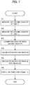
- FIG. 1 is a flowchart illustrating distance coefficient updating processing according to the embodiments.
- the updating device measures two ground objects by using the external field sensor at a time T 1 .
- the updating device measures the same two ground objects as those measured at the time T 1 , at a time T 2 ⁇ T seconds elapsed from the time T 1 .
- the updating device acquires a relative distance between those two ground objects.
- the updating device calculates the moving distance ⁇ D of the vehicle from the time T 1 to the time T 2 by using the distances from the vehicle center position to each of the ground objects and the relative distance between the two ground objects acquired at the time T 1 and the time T 2 .
- the updating device calculates the moving distance d p per one pulse by using the average pulse width t p of the vehicle speed pulse signal between the time T 1 and the time T 2 , an elapsed time ⁇ T from the time T 1 to the time T 2 and the moving distance ⁇ D of the vehicle from the time T 1 to the time T 2 acquired in the process P4. Then, in the process P6, the updating device updates the distance coefficient ⁇ d by using the moving distance d p per one pulse acquired in the processes P5 and P6.
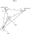
- FIG. 2 illustrates an example of a positional relation between two ground objects and a movable body traveling. It is assumed that the vehicle moved from the time T 1 to the time T 2 as shown in FIG. 2 .
- the updating device detects the ground object 1 and the ground object 2 at the time T 1 , and acquires the distance L 1 from the vehicle to the ground object 1 and the angle ⁇ 1 formed by the traveling direction Hd of the vehicle and the direction of the ground object 1 as well as the distance L 2 from the vehicle to the ground object 2 and the angle ⁇ 2 formed by the traveling direction Hd of the vehicle and the direction of the ground object 2 (Process P1) .
- the relative distance L between the ground object 1 and the ground object 2 can be calculated as follows by using L 1 , L 2 , ⁇ 1 , ⁇ 2 (Process P3) .
- the updating device detects the ground object 1 and the ground object 2 at the time T 2 similarly to the time T 1 , and acquires the distance L' 1 from the vehicle to the ground object 1 and the angle ⁇ ' 1 formed by the traveling direction Hd' of the vehicle and the direction of the ground object 1 as well as the distance L' 2 from the vehicle to the ground object 2 and the angle ⁇ ' 2 formed by the traveling direction Hd' of the vehicle and the direction of the ground object 2 (Process P2).
- the relative distance between the ground objects can be calculated by using L' 1 , L' 2 , ⁇ ' 1 , ⁇ ' 2 .
- L ′ L 1 ′ 2 + L 2 ′ 2 ⁇ 2 L 1 ′ L 2 ′ cos ⁇ 1 ′ + ⁇ 2 ′
- the updating device uses either one of the relative distance L and L' between the ground objects.
- the relative distance L between the ground objects (hereinafter referred to as "inter-ground-object distance L") is acquired by an arithmetic operation based on the measurement results of the ground objects by the external field sensor.
- the inter-ground-object distance L may be acquired from the high precision map data.
- the inter-ground-object distance L may vary dependently upon the measurement accuracy of the ground objects. Namely, if the measurement accuracy is low, the accuracy of the calculated inter-ground-object distance L becomes low and the accuracy of the moving distance ⁇ D of the vehicle calculated thereafter also becomes low.
- the inter-ground-object distance L may be acquired with high accuracy, and hence the accuracy of the moving distance ⁇ D of the vehicle may be improved.
- the updating device calculates the moving distance ⁇ D of the vehicle from the time T 1 to the time T 2 by using the distances L 1 , L 2 acquired at the time T 1 , the distances L' 1 , L' 2 acquired at the time T 2 and the inter-ground-object distance L.
- FIG. 3 illustrates a calculation method of the moving distance ⁇ D.
- the angle ⁇ is calculated by the cosine theorem as follows .
- the angle ⁇ is calculated by the cosine theorem as follows.
- the moving distance ⁇ D is calculated by using the angles ⁇ , ⁇ on the ground object 2 side in FIG. 3
- the moving distance ⁇ D may be calculated by using the angles ⁇ ', ⁇ ' on the ground object 1 side instead.
- an average value of the moving distances ⁇ D calculated by the above methods may be calculated.
- the updating device calculates the moving distance d p per one pulse as follows by using the moving distance ⁇ D of the vehicle in the time period ⁇ T from the time T 1 to the time T 2 and the average pulse width t p of the vehicle speed pulse signal.
- d p ⁇ D ⁇ T ⁇ t p
- FIG. 4 is a diagram explaining the average pulse width t p .
- the average pulse width t p may be calculated by buffering the pulse widths measured from the time T 1 and to the time T 2 and averaging them by the following equation (10).
- FIG. 5 is a flowchart of the processing for calculating the average pulse width by the sequential calculation.
- the updating device resets the coefficient k indicating the number of detected pulses to "0" (step S51), and acquire the current time T (step S52) .
- the updating device determines whether or not the current time T becomes the time T 2 (step S53) .
- step S53 the updating device detects the vehicle speed pulse signal and acquires the pulse width t k (step S54). Next, the updating device increments the coefficient kby "1" (stepS55), and determines whether or not the coefficient k is equal to "1" (step S56).
- step S56 If the coefficient k is equal to "1" (step S56: YES), the updating device substitutes the pulse width t k for the average pulse width t p (step S58), and returns to step S52.
- step S56: NO If the coefficient k is not equal to "1" (step S56: NO), the updating device adds the value (t k -t p )/k calculated by subtracting the difference between the average pulse width t p at that time and the pulse width t k at present by the coefficient k, i.e., the variation of the average pulse width t p due to the pulse width t k at present, to the average pulse width t p at that time to update the average pulse width t p , and returns to step S52. Then, if the current time T becomes the time T 2 (step S53: YES), the processing ends.
- the updating device updates the distance coefficient ⁇ d by using the moving distance d p acquired in the process P5. Specifically, the updating device sets the moving distance d p to a new distance coefficient ⁇ d .
- the distance coefficient ⁇ d thus updated is used for the calculation of the vehicle speed v by the equation (1).
- the distances L1, L2, L'1, L'2 are calculated as the distance in the three-dimensional space, i.e., as the direct distance from the external field sensor loaded on the vehicle to the ground object.
- the accuracy can be improved by calculating the distance from the vehicle to the ground object in case of projecting the position of the ground object to the horizontal plane of the vehicle (hereinafter referred to as "horizontal distance"). This method will be described below.
- a vehicle coordinate system (XYZ coordinate system) is defined as shown in FIG. 6B .
- the X-axis indicates the traveling direction of the vehicle
- the Y-axis indicates a direction perpendicular to the traveling direction of the vehicle within the horizontal plane of the vehicle
- the Z-axis indicates the height direction of the vehicle.
- the three-dimensional coordinates of the ground object can be acquired by using the external field sensor such as an onboard camera capable of measuring the three-dimensional position of the ground object, or in a case where the three-dimensional coordinate data is included in the map data, it is now assumed that the three-dimensional coordinate P of the ground object in the vehicle coordinate system can be acquired. It is noted that the horizontal plane of the vehicle (XY plane of the vehicle coordinate system) and the road plane are parallel with each other.
- the length L xy of the segment OP' and the angle ⁇ xy formed by the segment OP' and the X-axis can be calculated as follows.
- the horizontal distance L xy and the angle ⁇ xy may be used instead of the distance L 1 , L 2 .
- the horizontal distances L 1xy , L 2Xy are calculated instead of the distances L 1 , L 2
- the angles ⁇ 1xy , ⁇ 2xy are calculated instead of the angles ⁇ 1 , ⁇ 2 .
- the horizontal distances L' 1xy , L' 2xy are calculated instead of the distances L' 1 , L' 2
- the angles ⁇ ' 1xy , ⁇ ' 2xy are calculated instead of the angles ⁇ ' 1 , ⁇ ' 2 .
- the inter-ground-object distances L and L' are calculated based on them in the process P2, and the moving distance ⁇ D is calculated in the process P4.
- the distance L to the ground object and two deflection angles (the angle ⁇ xy formed by L xy obtained by projecting the segment of the distance L to the XY plane and the X-axis, and the angle ⁇ z formed by the segment of the distance L and the Z-axis) in the vehicle coordinate system can be acquired by using the external field sensor capable of measuring the distance to and angle of the ground object as shown in FIG. 7 .
- the horizontal plane of the vehicle (the XY plane in the vehicle coordinate system) and the road plane are parallel with each other.
- the horizontal distance L xy and the angle ⁇ xy may be used instead of the distance L and the angle ⁇ in the three-dimensional space.
- FIG. 8 is a block diagram illustrating a configuration of the updating device 1 according to the first embodiment.
- the updating device 1 calculates the inter-ground-object distance L by arithmetic operation based on the measurement results of two ground objects by the external field sensor.
- the updating device 1 includes a gyro sensor 10, a vehicle speed sensor 11, an external field sensor 12, a traveling direction acquiring unit 13, a vehicle speed pulse measuring unit 14, a ground object measuring unit 15, an inter-ground-object distance acquiring unit 16, a distance coefficient calibrating unit 17 and a moving distance calculating unit 18.
- the traveling direction acquiring unit 13, the vehicle speed pulse measuring unit 14, the ground object measuring unit 15, the inter-ground-object distance acquiring unit 16, the distance coefficient calibrating unit 17 and the moving distance calculating unit 18 may be realized by a computer such as a CPU which executes a program prepared in advance.
- the traveling direction acquiring unit 13 acquires the traveling direction Hd of the vehicle based on the output from the gyro sensor 10, and supplies it to the ground object measuring unit 15 and the distance coefficient calibrating unit 17.
- the vehicle speed pulse measuring unit 14 measures the vehicle speed pulses outputted from the vehicle speed sensor 11, calculates the average pulse width t p of the vehicle speed pulse signal and supplies it to the distance coefficient calibrating unit 17.
- the external field sensor 12 may be a camera, a LiDAR and amillimeter wave radar, for example, and the ground object measuring unit 15 measures the distance to the ground object based on the output from the external field sensor 12 . Specifically, the ground object measuring unit 15 measures the distances L 1 , L 2 from the vehicle to the two ground objects at the time T 1 , calculates the angles ⁇ 1 , ⁇ 2 formed by the traveling direction Hd supplied from the traveling direction acquiring unit 13 and the directions of the two ground objects, and supplies them to the inter-ground-object distance acquiring unit 16 and the moving distance calculating unit 18.
- the ground object measuring unit 15 measures the distances L' 1 , L' 2 from the vehicle to the two ground objects at the time T 2 , calculates the angles ⁇ ' 1 , ⁇ ' 2 formed by the traveling direction Hd' supplied from the traveling direction acquiring unit 13 and the directions of the two ground objects, and supplies them to the inter-ground-object distance acquiring unit 16 and the moving distance calculating unit 18.
- the inter-ground-object distance acquiring unit 16 calculates the inter-ground-object distance L by the above equation (3) based on the distances L 1 , L 2 and the angles ⁇ 1 , ⁇ 2 for the two ground objects measured by the ground object measuring unit 15, and supplies them to the moving distance calculating unit 18.
- the moving distance calculating unit 18 calculates the moving distance ⁇ D of the vehicle by the above equations (6) to (8) based on the distances L 1 , L 2 , L' 1 , L' 2 supplied from the ground object measuring unit 15 and the inter-ground-object distance L calculated by the inter-ground-object distance acquiring unit 16, and supplies it to the distance coefficient calibrating unit 17.
- the distance coefficient calibrating unit 17 calculates the moving distance d p per one pulse (i.e., the distance coefficient ⁇ d ) based on the average pulse width t p supplied from the vehicle speed pulse measuring unit 14 and the moving distance ⁇ D supplied from the moving distance calculating unit 18. From the moving distance per one pulse, the vehicle speed may be calculated.
- FIG. 9 is a flowchart of the distance coefficient updating processing according to the first embodiment.
- the updating device 1 determines whether or not the vehicle is traveling straight based on the traveling direction of the vehicle outputted by the traveling direction acquiring unit 13 (step S11). This is because, if the vehicle is not traveling straight, the accuracy of the moving distance ⁇ D outputted by the moving distance calculating unit 18 is deteriorated. Specifically, in a case where the gyro sensor 10 can detect the angular velocity ⁇ in the yaw direction of the vehicle, the updating device 1 may determine that the vehicle is traveling straight when
- step S11 When the vehicle is not traveling straight (step S11: NO), the processing ends. On the other hand, when the vehicle is traveling straight (step S11: YES), the updating device 1 measures two ground objects 1 and 2 (step S12), and calculates the relative distance L between them (step S13).
- step S14 YES
- the updating device 1 sets "1" to "flag” (step S15), starts the calculation of the average pulse width t p (step S16), and returns to step S11.
- step S14 NO
- the updating device 1 calculates the moving distance ⁇ D as described above (step S17), calculates the moving distance d p per one pulse by using the moving distance ⁇ D (step S18), and updates the distance coefficient ⁇ d (step S19). Then, the processing ends.
- FIG. 10 is a block diagram illustrating a configuration of an updating device 1x according to the second embodiment. While the updating device 1x is different from the updating device 1 in that the updating device 1x includes a map database (DB) 19 storing high precision map data, other constitutive elements are the same as the updating device 1 of the first embodiment, and therefore the description thereof will be omitted.
- DB map database
- the inter-ground-object distance acquiring unit 16 acquires the inter-ground-object distance L between the two ground objects by using the high precision map data stored in the map DB 19.
- FIG. 11 is a flowchart illustrating the distance coefficient updating processing according to the second embodiment.
- the distance coefficient updating processing according to the second embodiment is different in that the inter-ground-object distance L is acquired from the map DB in step S26 instead of step S13 in the first embodiment, but other steps are basically the same as the distance coefficient updating processing according to the first embodiment.
- steps S21 to S22, S23 to S25, S27 to S29 are the same as steps S11 to S12, S14 to S16, S17 to S19 in the distance coefficient updating processing according to the first embodiment, respectively.
- the moving distance d p per one pulse calculated in the above distance coefficient updating processing is the average of the moving distances per one pulse in the time interval ⁇ T from the time T 1 to the time T 2 . Therefore, if the variation of the pulse widths in the time interval ⁇ T is large, the accuracy of the calculated moving distance d p is deteriorated. Accordingly, it is desired that the number of pulses in the time interval ⁇ T is as small as possible.
- the number of pulses in a unit time is different dependently upon the traveling speed of the vehicle. For example, as shown in FIG. 12A , the number of pulses in one second is considered. In a type of vehicle in which two pulses are outputted during one revolution of the tire, the number of pulses per one second is 3 pulses at 10km/h, 17 pulses at 50km/h and 35 pulses at 100km/h, and is largely different dependently upon the traveling speed.
- FIG. 12B illustrates the relation between the traveling speed and the pulse width.
- the time interval ⁇ T is set to 300ms when the traveling speed is lower than 20km/h, set to 200ms when the traveling speed is higher than 20km/h and lower than 30km/h, set to 100ms when the traveling speed is higher than 30km/h and lower than 60km/h and set to 50ms when the traveling speed is higher than 60km/h.
- the number of pulses measured in the time interval ⁇ T becomes one or two, and the moving distance d p can be calculated with high accuracy.
- the moving distance may be calculated by the following method.
- the combinations of the ground object 1 and the ground object 2, the ground object 2 and the ground object 3, the ground object 3 and the ground object 1 can be selected as shown in FIG. 13 .
- the moving distance from the time T 1 to the time T 2 is calculated by the method of the processes P1 to P3 described above.
- the moving distance acquired from the combination of the ground object 1 and the ground object 2 is indicated as " ⁇ D 12 "
- the moving distance acquired from the combination of the ground object 2 and the ground object 3 is indicated as " ⁇ D 23 "
- the moving distance acquired from the combination of the ground object 3 and the ground object 1 is indicated as " ⁇ D 31 "
- the average value of them acquired by the following equation can be used as the moving distance ⁇ D.
- ⁇ D ⁇ D 12 + ⁇ D 23 + ⁇ D 31 3
- the accuracy of the moving distance ⁇ D may be statistically improved, and the accuracy of the moving distance per one pulse may be improved.
- three or more ground objects are measured at the same time, and the moving distance is calculated based on the combination of two ground objects having high reliability, thereby acquiring moving distance with high accuracy.
- the accuracy of the measurement by the external field sensor is deteriorated as the distance becomes long. Therefore, when three or more ground objects can be measured at the same time, two ground objects nearest and second nearest from the vehicle are selected, and the moving distance is acquired based on them by the method of the first embodiment or the second embodiment.
- the updating device may acquire the moving distance ⁇ D by using the nearest and the second nearest ground objects from the vehicle, i.e., the ground object 1 and the ground object 3.
- the distances between the ground objects are compared with the threshold L th .
- L 12 ⁇ L th , L 23 >L th , L 31 >L th it is assumed that: L 12 ⁇ L th , L 23 >L th , L 31 >L th .
- the combination for which the distance between the ground objects is shorter than the threshold value L TH i.e., the combination of the ground object 1 and the ground object 2 is excluded, and the moving distance ⁇ D may be acquired by using the combination of the ground object 2 and the ground object 3 and the combination of the ground object 1 and the ground object 3.
- the updating device may acquire the moving distance ⁇ D based on the combination of the ground object 1 and the ground object 3.
- the moving distance ⁇ D may be determined as the average value of the moving distance ⁇ D 12 acquired from the combination of the ground object 1 and the ground object 2 and the moving distance ⁇ D 31 acquired from the combination of the ground object 1 and the ground object 3. While a predetermined distance is determined as the threshold value L th , an average value of the inter-ground-object distances between three or more measured ground objects may be used as the threshold value L th .
- the inter-ground-object distance L is calculated from the measurement results of two ground objects in the first embodiment, and the inter-ground-object distance L is acquired by using the map data in the second embodiment.
- the above two methods may be used in combination.
- the inter-ground-object distance L may be acquired by using the high precision map data in the area where the high precision map data exists, and the inter-ground-object distance L may be calculated from the measurement results of the ground objects in the area where the high precision map data does not exist.
- one of the inter-ground-object distances L having higher accuracy may be used.
- the distance coefficient updating processing of the embodiments basically updates the distance coefficient while the vehicle is traveling straight.
- the moving distance ⁇ D acquired in the process P3 is not the actual moving distance but an approximate value. Accordingly, if the time interval ⁇ T is too large, the difference between the actual moving distance and the moving distance calculated in the process P4 becomes large. In this view, it is desired to make the time interval ⁇ T from the time T 1 to the time T 2 as short as possible.
- the external field sensor is mounted on a low position of the vehicle, occlusion by surrounding vehicles increases, and the frequency of detecting the ground objects suitable for updating the distance coefficient may decrease. Therefore, it is preferred that the external field sensor is mounted on a position to measure areas higher than the heights of the surrounding vehicles. Thus, the frequency of detecting the ground objects increases, the frequency of updating the distance coefficient also increases, and the accuracy of the distance coefficient can be improved.
- This invention can be used for a device loaded on a movable body.
Landscapes
- Engineering & Computer Science (AREA)
- Physics & Mathematics (AREA)
- Radar, Positioning & Navigation (AREA)
- Remote Sensing (AREA)
- General Physics & Mathematics (AREA)
- Electromagnetism (AREA)
- Computer Networks & Wireless Communication (AREA)
- Computer Vision & Pattern Recognition (AREA)
- Theoretical Computer Science (AREA)
- Navigation (AREA)
- Traffic Control Systems (AREA)
- Radar Systems Or Details Thereof (AREA)
Description
- The present invention relates to a technique of estimating a moving distance of a movable body.
- Patent Reference-1 discloses a technique of correcting a vehicle speed sensor installed in a movable body by estimating a moving distance of the movable body in a predetermined time period, for example. In Patent Reference-1, the correction device detects a number of output pulses of the vehicle speed sensor after the image recognition means recognizes a ground object A until the image recognition means recognizes a ground object B, and acquires a distance D between the ground object A and the ground object B from map information. Then, the correction device corrects an arithmetic expression for calculating a traveling distance or a traveling speed of a vehicle from the number of output pulses, based on the relation between the number of output pulses and the distance D.
- The article "Triangulation of Mobile Robot Position with Detected Inherent Environment Landmarks", by L. Jurisica and F. Duchon, in: "International Journal of Mechanics and Control, Vol", 1 December 2009 (2009-12-01), discloses a method for determining the displacement of a robot on the basis of distances to and between landmarks. Document
US2014/0046587 discloses a technique for calibrating an odometer using measured distances to two landmarks. - Patent Reference-1: Japanese Patent Application Laid-Open under No.
2008-8783 - However, according to the method of Patent Reference-1, since the image recognition means can recognize only one ground object at one time, the correction device can use only a ground object existing on a road on which the vehicle is traveling, such as a road sign painted on a road.
- The above is an example of the problem to be solved by the present invention. It is an object of the present invention to estimate a traveling distance of a movable body by utilizing arbitrary ground objects.
- An invention described in claims is a distance estimation device according to
claim 1. - Another invention described in claims is a distance estimation method according to
claim 10. - Still another invention described in claims is a program according to
claim 11. -
-
FIG. 1 is a flowchart illustrating distance coefficient updating processing according to embodiments. -
FIG. 2 illustrates a relation between two ground objects and a moving vehicle. -
FIG. 3 illustrates a method of calculating a moving distance of the vehicle. -
FIG. 4 is a diagram for explaining an average pulse width. -
FIG. 5 is a flowchart of processing for calculating the average pulse width by sequential calculation. -
FIGS. 6A to 6C illustrate a method of projecting a three-dimensional position of the ground object to the horizontal plane of the vehicle. -
FIG. 7 illustrates another method of projecting a three-dimensional position of the ground object to the horizontal plane of the vehicle. -
FIG. 8 is a block diagram illustrating a configuration of a distance coefficient updating device according to a first embodiment. -
FIG. 9 is a flowchart of distance coefficient updating processing according to the first embodiment. -
FIG. 10 is a block diagram illustrating a configuration of a distance coefficient updating device according to a second embodiment. -
FIG. 11 is a flowchart of distance coefficient updating processing according to the second embodiment. -
FIGS . 12A and 12B illustrate a relation between a traveling speed and a number of pulses in a unit time, and a relation between the traveling speed and a pulse width. -
FIG. 13 illustrates a positional relation between three ground objects and a moving vehicle. -
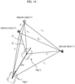
FIG. 14 illustrates another positional relation between three ground objects and a moving vehicle. - According to one aspect of the present invention, there is provided a distance estimation device comprising: an acquiring unit configured to acquire a first distance group and a second distance group including distances from a movable body at a first time and a second time to at least three ground objects and a third distance group including distances between the at least three ground objects; and a calculating unit configured to calculate a moving distance of the movable body from the first time to the second time based on the distances from the movable body to the ground objects and the distances between the ground objects with respect to two ground objects specified based on the distances to the at least three ground objects or the distances between the at least three ground objects.
- The above distance estimation device acquires a first distance group and a second distance group including distances from a movable body at a first time and a second time to at least three ground objects and a third distance group including distances between the at least three ground objects. Then, the distance estimation device calculates a moving distance of the movable body from the first time to the second dime based on the distances from the movable body to the ground objects and the distances between the ground objects with respect to two ground objects specified based on the distances to the at least three ground objects or the distances between the at least three ground objects. Thus, the moving distance of the movable body can be calculated using arbitrary ground objects measurable from the movable body.
- In one mode of the above distance estimation device, the calculating unit specifies, out of the at least three ground objects, two ground objects whose distance from the movable body is short as the two ground objects. In another mode, the calculating unit excludes two ground objects, for which the distance between the ground objects is shorter than a predetermined distance, from the two ground objects to be specified by the calculating unit.
- In still another mode of the above distance estimation device, the calculating unit calculates the moving distance per one pulse of a vehicle speed pulse signal, based on the moving distance from the first time to the second time and an average pulse width of the vehicle speed pulse signal. Thus, the vehicle speed pulse signal can be calibrated based on the calculated moving distance.
- In still another mode of the above distance estimation device, the calculating unit calculates the moving distance when an angular velocity in a yaw direction or a steering angle of the movable body is smaller than a predetermined threshold value . Thus, accuracy of calculating the moving distance may be improved.
- In a preferred example of the above distance estimation device, the calculating unit acquires the distance between the two ground objects based on the distances to the two ground objects and angles formed by a traveling direction of the movable body and respective directions of the two ground objects. In another preferred example, the calculating unit acquires the distance between the two ground objects based on map information.
- In still another mode of the above distance estimation device, the calculating unit changes a time interval from the first time to the second time in accordance with a traveling speed of the movable body. Thus, accuracy of calculating the moving distance may be improved. Preferably, the calculating unit makes the time interval shorter as the traveling speed of the movable body becomes higher.
- According another aspect of the present invention, there is provided a distance estimation method executed by a distance estimation device comprising: an acquiring process configured to acquire a first distance group and a second distance group including distances from a movable body at a first time and a second time to at least three ground objects and a third distance group including distances between the at least three ground objects; and a calculating process configured to calculate a moving distance of the movable body from the first time to the second time based on the distances from the movable body to the ground objects and the distances between the ground objects with respect to two ground objects specified based on the distances to the at least three ground objects or the distances between the at least three ground objects. Thus, the moving distance of the movable body can be calculated using arbitrary ground objects measurable from the movable body.
- According to still another aspect of the present invention, there is provided a program executed by a distance estimation device comprising a computer, the program causing the computer to function as : an acquiring unit configured to acquire a first distance group and a second distance group including distances from a movable body at a first time and a second time to at least three ground objects and a third distance group including distances between the at least three ground objects; and a calculating unit configured to calculate a moving distance of the movable body from the first time to the second time based on the distances from the movable body to the ground objects and the distances between the ground objects with respect to two ground objects specified based on the distances to the at least three ground objects or the distances between the at least three ground objects. Thus, the moving distance of the movable body can be calculated using arbitrary ground objects measurable from the movable body. The above program can be used in a manner stored on a storage medium.
- Preferred embodiments of the present invention will be described below with reference to the attached drawings. The following description will be directed to the embodiments wherein a moving distance of a movable body acquired by a distance estimation method of the present invention is used in calibration of the vehicle speed pulses of the vehicle.
- A self-position estimation system installed in a present car navigation device detects a vehicle speed by a vehicle speed sensor and a traveling direction by an angular velocity sensor or a steering angle sensor, thereby to measure a moving state of the vehicle, and estimates a current position by integrating those information with information measured by a GPS or an external field sensor. Therefore, in order to improve accuracy of estimating the self-position, it is required to detect the vehicle speed with high accuracy.
- The vehicle speed sensor outputs a vehicle speed pulse signal at the time interval proportional to the rotational speed of the output shaft of the transmission or the wheels, for example. Then, as indicated by the following equation (1), the vehicle speed v can be calculated by dividing the distance coefficient α d by the pulse width tp. This distance coefficient α d is a moving distance per one pulse of the vehicle speed pulse signal.

- Conventionally, when the distance coefficient is calibrated, information acquired from the GPS is used as a reference . For example, the moving distance dp per one pulse is calculated by the following equation (2) using the vehicle moving distance ΔD calculated from the GPS position obtained from the GPS and the number n of the vehicle speed pulses, and the correction is constantly made by applying averaging processing.

- However, according to the condition, the GPS information itself, serving as the reference, may include large error, and when the calibration calculation is made by using the GPS information including large error as the reference, the distance coefficient may deviate from a true value . In order to obtain the GPS information used as the reference more accurately, the condition should be made stricter. However, as the condition is made stricter, there occurs such a conflicting problem that the reference information can be obtained less frequently and the progress of the calibration becomes slow.
- In the above view, a distance coefficient updating device (hereinafter simply referred to as "updating device") does not use the GPS information as the reference, and calculates the moving distance of the vehicle based on the measurement of the ground objects by the external field sensor and uses it as the reference for calibrating the vehicle speed pulse signal. As the external field sensor, a camera, a LiDAR (Light Detection And Ranging) or a millimeter wave radar may be used.
-
FIG. 1 is a flowchart illustrating distance coefficient updating processing according to the embodiments. First, in the process P1, the updating device measures two ground objects by using the external field sensor at a time T1. Next, in the process P2, the updating device measures the same two ground objects as those measured at the time T1, at a time T2 ΔT seconds elapsed from the time T1. Next, in the process P3, the updating device acquires a relative distance between those two ground objects. - Next, in the process P4, the updating device calculates the moving distance ΔD of the vehicle from the time T1 to the time T2 by using the distances from the vehicle center position to each of the ground objects and the relative distance between the two ground objects acquired at the time T1 and the time T2.
- Next, in the process P5, the updating device calculates the moving distance dp per one pulse by using the average pulse width tp of the vehicle speed pulse signal between the time T1 and the time T2, an elapsed time ΔT from the time T1 to the time T2 and the moving distance ΔD of the vehicle from the time T1 to the time T2 acquired in the process P4. Then, in the process P6, the updating device updates the distance coefficient α d by using the moving distance dp per one pulse acquired in the processes P5 and P6.
- Next, each process in the above distance coefficient updating processing will be described in detail.
-
FIG. 2 illustrates an example of a positional relation between two ground objects and a movable body traveling. It is assumed that the vehicle moved from the time T1 to the time T2 as shown inFIG. 2 . First, the updating device detects theground object 1 and theground object 2 at the time T1, and acquires the distance L1 from the vehicle to theground object 1 and the angle φ 1 formed by the traveling direction Hd of the vehicle and the direction of theground object 1 as well as the distance L2 from the vehicle to theground object 2 and the angle φ 2 formed by the traveling direction Hd of the vehicle and the direction of the ground object 2 (Process P1) . At this time, the relative distance L between theground object 1 and theground object 2 can be calculated as follows by using L1, L2, φ 1, φ 2 (Process P3) .
- Next, the updating device detects the
ground object 1 and theground object 2 at the time T2 similarly to the time T1, and acquires the distance L'1 from the vehicle to theground object 1 and the angle φ '1 formed by the traveling direction Hd' of the vehicle and the direction of theground object 1 as well as the distance L'2 from the vehicle to theground object 2 and the angle φ'2 formed by the traveling direction Hd' of the vehicle and the direction of the ground object 2 (Process P2). At this time, similarly to the time T1, the relative distance between the ground objects can be calculated by using L'1, L'2, φ'1, φ'2. The relative distance L' between the ground objects at the time T2 is calculated by the following equation (Process P3).
- When the moving distance ΔD of the vehicle is calculated in the process P4 described later, the updating device uses either one of the relative distance L and L' between the ground objects. Alternatively, the updating device may calculate an average value Lave of the relative distances L and L' by the following equation and use it.

- In the following description, the relative distance between the ground objects will be expressed as "L".
- In the above example, in the process P3, the relative distance L between the ground objects (hereinafter referred to as "inter-ground-object distance L") is acquired by an arithmetic operation based on the measurement results of the ground objects by the external field sensor. However, if high precision map data is available, the inter-ground-object distance L may be acquired from the high precision map data. In a case where the inter-ground-object distance L is calculated from the measurement results of the ground objects by the external field sensor, the inter-ground-object distance L may vary dependently upon the measurement accuracy of the ground objects. Namely, if the measurement accuracy is low, the accuracy of the calculated inter-ground-object distance L becomes low and the accuracy of the moving distance ΔD of the vehicle calculated thereafter also becomes low. In this respect, if the high precision map data is used, the inter-ground-object distance L may be acquired with high accuracy, and hence the accuracy of the moving distance ΔD of the vehicle may be improved.
- Next, the updating device calculates the moving distance ΔD of the vehicle from the time T1 to the time T2 by using the distances L1, L2 acquired at the time T1, the distances L'1, L'2 acquired at the time T2 and the inter-ground-object distance L.
FIG. 3 illustrates a calculation method of the moving distance ΔD. InFIG. 3 , the angle α is calculated by the cosine theorem as follows .
- Similarly, the angle β is calculated by the cosine theorem as follows.

- Therefore, the moving distance ΔD is calculated by the cosine theorem as follows.

- While the moving distance ΔD is calculated by using the angles α, β on the
ground object 2 side inFIG. 3 , the moving distance ΔD may be calculated by using the angles α', β' on theground object 1 side instead. Alternatively, an average value of the moving distances ΔD calculated by the above methods may be calculated. - Next, the updating device calculates the moving distance dp per one pulse as follows by using the moving distance ΔD of the vehicle in the time period ΔT from the time T1 to the time T2 and the average pulse width tp of the vehicle speed pulse signal.

-
FIG. 4 is a diagram explaining the average pulse width tp. The average pulse width tp may be calculated by buffering the pulse widths measured from the time T1 and to the time T2 and averaging them by the following equation (10).
- Instead, the average pulse width tp may be calculated by a sequential calculation using the equation (11) . If the average pulse width tp is calculated by the sequential calculation, it is not necessary to buffer the measured pulse widths and hence the usage amount of the memory in the device may be reduced.

-
FIG. 5 is a flowchart of the processing for calculating the average pulse width by the sequential calculation. First, at the time T=T1, the updating device resets the coefficient k indicating the number of detected pulses to "0" (step S51), and acquire the current time T (step S52) . Next, the updating device determines whether or not the current time T becomes the time T2 (step S53) . - If the current time T does not become the time T2 (step S53: NO), the updating device detects the vehicle speed pulse signal and acquires the pulse width tk (step S54). Next, the updating device increments the coefficient kby "1" (stepS55), and determines whether or not the coefficient k is equal to "1" (step S56).
- If the coefficient k is equal to "1" (step S56: YES), the updating device substitutes the pulse width tk for the average pulse width tp (step S58), and returns to step S52. On the contrary, if the coefficient k is not equal to "1" (step S56: NO), the updating device adds the value (tk-tp)/k calculated by subtracting the difference between the average pulse width tp at that time and the pulse width tk at present by the coefficient k, i.e., the variation of the average pulse width tp due to the pulse width tk at present, to the average pulse width tp at that time to update the average pulse width tp, and returns to step S52. Then, if the current time T becomes the time T2 (step S53: YES), the processing ends.
- Next, the updating device updates the distance coefficient α d by using the moving distance dp acquired in the process P5. Specifically, the updating device sets the moving distance dp to a new distance coefficient α d. The distance coefficient α d thus updated is used for the calculation of the vehicle speed v by the equation (1).
- In the above description, the distances L1, L2, L'1, L'2 are calculated as the distance in the three-dimensional space, i.e., as the direct distance from the external field sensor loaded on the vehicle to the ground object. However, when the ground object exists at a high position from the horizontal plane (road plane) of the vehicle as shown in
FIG. 6A , the accuracy can be improved by calculating the distance from the vehicle to the ground object in case of projecting the position of the ground object to the horizontal plane of the vehicle (hereinafter referred to as "horizontal distance"). This method will be described below. - Now, it is assumed that a vehicle coordinate system (XYZ coordinate system) is defined as shown in
FIG. 6B . Here, the X-axis indicates the traveling direction of the vehicle, the Y-axis indicates a direction perpendicular to the traveling direction of the vehicle within the horizontal plane of the vehicle, and the Z-axis indicates the height direction of the vehicle. - In a case where the three-dimensional coordinates of the ground object can be acquired by using the external field sensor such as an onboard camera capable of measuring the three-dimensional position of the ground object, or in a case where the three-dimensional coordinate data is included in the map data, it is now assumed that the three-dimensional coordinate P of the ground object in the vehicle coordinate system can be acquired. It is noted that the horizontal plane of the vehicle (XY plane of the vehicle coordinate system) and the road plane are parallel with each other.
- In this case, supposing that the orthographic projection from the point P to the XY plane (the foot of the perpendicular line drawn from the point P to the XY plane) is the point P', the length Lxy of the segment OP' and the angle φ xy formed by the segment OP' and the X-axis can be calculated as follows.


- Therefore, in the processing of the processes P1 to P4, instead of the distance L to the ground object and the angle φ of the ground object in the three-dimensional space, the horizontal distance Lxy and the angle φ xy may be used. Specifically, in the process P1, the horizontal distances L1xy, L2Xy are calculated instead of the distances L1, L2, and the angles φ 1xy, φ 2xy are calculated instead of the angles φ 1, φ 2. Similarly, in the process P2, the horizontal distances L'1xy, L'2xy are calculated instead of the distances L'1, L'2, and the angles φ'1xy, φ'2xy are calculated instead of the angles φ'1, φ'2. Then, the inter-ground-object distances L and L' are calculated based on them in the process P2, and the moving distance ΔD is calculated in the process P4.
- It is assumed that the distance L to the ground object and two deflection angles (the angle φ xy formed by Lxy obtained by projecting the segment of the distance L to the XY plane and the X-axis, and the angle φ z formed by the segment of the distance L and the Z-axis) in the vehicle coordinate system can be acquired by using the external field sensor capable of measuring the distance to and angle of the ground object as shown in
FIG. 7 . Here, it is assumed that the horizontal plane of the vehicle (the XY plane in the vehicle coordinate system) and the road plane are parallel with each other. - In this case, supposing that the orthographic projection from the point P to the XY plane (the foot of the perpendicular line drawn from the point P to the XY plane) is the point P', the length Lxy of the segment OP' can be calculated as follows.

- Therefore, similarly to the above case, in the processing in the processes P1 to P4, the horizontal distance Lxy and the angle φ xy may be used instead of the distance L and the angle φ in the three-dimensional space.
- Next, the first embodiment of the above updating device will be described.
FIG. 8 is a block diagram illustrating a configuration of the updatingdevice 1 according to the first embodiment. In the first embodiment, the updatingdevice 1 calculates the inter-ground-object distance L by arithmetic operation based on the measurement results of two ground objects by the external field sensor. - As illustrated, the updating
device 1 includes agyro sensor 10, avehicle speed sensor 11, anexternal field sensor 12, a travelingdirection acquiring unit 13, a vehicle speedpulse measuring unit 14, a groundobject measuring unit 15, an inter-ground-objectdistance acquiring unit 16, a distancecoefficient calibrating unit 17 and a movingdistance calculating unit 18. The travelingdirection acquiring unit 13, the vehicle speedpulse measuring unit 14, the groundobject measuring unit 15, the inter-ground-objectdistance acquiring unit 16, the distancecoefficient calibrating unit 17 and the movingdistance calculating unit 18 may be realized by a computer such as a CPU which executes a program prepared in advance. - The traveling
direction acquiring unit 13 acquires the traveling direction Hd of the vehicle based on the output from thegyro sensor 10, and supplies it to the groundobject measuring unit 15 and the distancecoefficient calibrating unit 17. The vehicle speedpulse measuring unit 14 measures the vehicle speed pulses outputted from thevehicle speed sensor 11, calculates the average pulse width tp of the vehicle speed pulse signal and supplies it to the distancecoefficient calibrating unit 17. - The
external field sensor 12 may be a camera, a LiDAR and amillimeter wave radar, for example, and the groundobject measuring unit 15 measures the distance to the ground object based on the output from theexternal field sensor 12 . Specifically, the groundobject measuring unit 15 measures the distances L1, L2 from the vehicle to the two ground objects at the time T1, calculates the angles φ 1, φ 2 formed by the traveling direction Hd supplied from the travelingdirection acquiring unit 13 and the directions of the two ground objects, and supplies them to the inter-ground-objectdistance acquiring unit 16 and the movingdistance calculating unit 18. Also, the groundobject measuring unit 15 measures the distances L'1, L'2 from the vehicle to the two ground objects at the time T2, calculates the angles φ'1, φ'2 formed by the traveling direction Hd' supplied from the travelingdirection acquiring unit 13 and the directions of the two ground objects, and supplies them to the inter-ground-objectdistance acquiring unit 16 and the movingdistance calculating unit 18. - The inter-ground-object
distance acquiring unit 16 calculates the inter-ground-object distance L by the above equation (3) based on the distances L1, L2 and the angles φ 1, φ 2 for the two ground objects measured by the groundobject measuring unit 15, and supplies them to the movingdistance calculating unit 18. - The moving
distance calculating unit 18 calculates the moving distance ΔD of the vehicle by the above equations (6) to (8) based on the distances L1, L2, L'1, L'2 supplied from the groundobject measuring unit 15 and the inter-ground-object distance L calculated by the inter-ground-objectdistance acquiring unit 16, and supplies it to the distancecoefficient calibrating unit 17. - The distance
coefficient calibrating unit 17 calculates the moving distance dp per one pulse (i.e., the distance coefficient αd) based on the average pulse width tp supplied from the vehicle speedpulse measuring unit 14 and the moving distance ΔD supplied from the movingdistance calculating unit 18. From the moving distance per one pulse, the vehicle speed may be calculated. - Next, the distance coefficient updating processing according to the first embodiment will be described.
FIG. 9 is a flowchart of the distance coefficient updating processing according to the first embodiment. - First, the updating
device 1 determines whether or not the vehicle is traveling straight based on the traveling direction of the vehicle outputted by the traveling direction acquiring unit 13 (step S11). This is because, if the vehicle is not traveling straight, the accuracy of the moving distance ΔD outputted by the movingdistance calculating unit 18 is deteriorated. Specifically, in a case where thegyro sensor 10 can detect the angular velocity ω in the yaw direction of the vehicle, the updatingdevice 1 may determine that the vehicle is traveling straight when |ω| <Δω (Δω predetermined threshold value) is established. Also, in a case where the steering angle δ of the vehicle can be detected, the updatingdevice 1 may determine that the vehicle is traveling straight when |δ| <Δ δ (Δδ :predetermined threshold value) is established. - When the vehicle is not traveling straight (step S11: NO), the processing ends. On the other hand, when the vehicle is traveling straight (step S11: YES), the updating
device 1 measures twoground objects 1 and 2 (step S12), and calculates the relative distance L between them (step S13). - Next, the updating
device 1 determines whether or not "flag=0" is established (step S14). It is noted that "flag" is reset at the start of the processing. When "flag=0" is established (step S14: YES), the updatingdevice 1 sets "1" to "flag" (step S15), starts the calculation of the average pulse width tp (step S16), and returns to step S11. - On the other hand, when "flag=0" is not established (step S14: NO), the updating
device 1 calculates the moving distance ΔD as described above (step S17), calculates the moving distance dp per one pulse by using the moving distance ΔD (step S18), and updates the distance coefficient α d (step S19). Then, the processing ends. - Next, the second embodiment of the above updating device will be described.
FIG. 10 is a block diagram illustrating a configuration of an updatingdevice 1x according to the second embodiment. While the updatingdevice 1x is different from the updatingdevice 1 in that the updatingdevice 1x includes a map database (DB) 19 storing high precision map data, other constitutive elements are the same as the updatingdevice 1 of the first embodiment, and therefore the description thereof will be omitted. - In the updating
device 1x of the second embodiment, the inter-ground-objectdistance acquiring unit 16 acquires the inter-ground-object distance L between the two ground objects by using the high precision map data stored in themap DB 19. -
FIG. 11 is a flowchart illustrating the distance coefficient updating processing according to the second embodiment. In comparison with the distance coefficient updating processing shown inFIG. 9 , the distance coefficient updating processing according to the second embodiment is different in that the inter-ground-object distance L is acquired from the map DB in step S26 instead of step S13 in the first embodiment, but other steps are basically the same as the distance coefficient updating processing according to the first embodiment. Specifically, steps S21 to S22, S23 to S25, S27 to S29 are the same as steps S11 to S12, S14 to S16, S17 to S19 in the distance coefficient updating processing according to the first embodiment, respectively. - The moving distance dp per one pulse calculated in the above distance coefficient updating processing is the average of the moving distances per one pulse in the time interval ΔT from the time T1 to the time T2. Therefore, if the variation of the pulse widths in the time interval ΔT is large, the accuracy of the calculated moving distance dp is deteriorated. Accordingly, it is desired that the number of pulses in the time interval ΔT is as small as possible.
- The number of pulses in a unit time is different dependently upon the traveling speed of the vehicle. For example, as shown in
FIG. 12A , the number of pulses in one second is considered. In a type of vehicle in which two pulses are outputted during one revolution of the tire, the number of pulses per one second is 3 pulses at 10km/h, 17 pulses at 50km/h and 35 pulses at 100km/h, and is largely different dependently upon the traveling speed. - Therefore, by changing the time interval ΔT according to the traveling speed in consideration of the measurement cycle of the external field sensor and the type of vehicle, it becomes possible to suppress the deterioration of the accuracy of the moving distance dp due to the variation of the pulse width.
FIG. 12B illustrates the relation between the traveling speed and the pulse width. For example, if the measurement cycle of the external field sensor is 50ms (20Hz) and the vehicle is of the type in which two pulses are outputted per one revolution of the tire, the time interval ΔT is set to 300ms when the traveling speed is lower than 20km/h, set to 200ms when the traveling speed is higher than 20km/h and lower than 30km/h, set to 100ms when the traveling speed is higher than 30km/h and lower than 60km/h and set to 50ms when the traveling speed is higher than 60km/h. Thus, the number of pulses measured in the time interval ΔT becomes one or two, and the moving distance dp can be calculated with high accuracy. - In the above distance coefficient updating processing, two ground objects are measured. However, if three or more ground objects can be measured at the same time, the moving distance may be calculated by the following method.
- When three or more ground objects can be measured at the same time, it is possible to calculate the moving distance ΔD in plural combinations and use the average value of them to update the distance coefficient.
- For example, if three ground objects can be measured, the combinations of the
ground object 1 and theground object 2, theground object 2 and theground object 3, theground object 3 and theground object 1 can be selected as shown inFIG. 13 . For each combination, the moving distance from the time T1 to the time T2 is calculated by the method of the processes P1 to P3 described above. When the moving distance acquired from the combination of theground object 1 and theground object 2 is indicated as "ΔD12", the moving distance acquired from the combination of theground object 2 and theground object 3 is indicated as "ΔD23" the moving distance acquired from the combination of theground object 3 and theground object 1 is indicated as "ΔD31", the average value of them acquired by the following equation can be used as the moving distance ΔD.
- Thus, the accuracy of the moving distance ΔD may be statistically improved, and the accuracy of the moving distance per one pulse may be improved.
- According to the invention, three or more ground objects are measured at the same time, and the moving distance is calculated based on the combination of two ground objects having high reliability, thereby acquiring moving distance with high accuracy. Generally, the accuracy of the measurement by the external field sensor is deteriorated as the distance becomes long. Therefore, when three or more ground objects can be measured at the same time, two ground objects nearest and second nearest from the vehicle are selected, and the moving distance is acquired based on them by the method of the first embodiment or the second embodiment.
- For example, when three
ground objects 1 to 3 can be measured like the example ofFIG. 13 , the distances from the vehicle to those three ground objects has the relation: L1<L3<L2. Therefore, the updating device may acquire the moving distance ΔD by using the nearest and the second nearest ground objects from the vehicle, i.e., theground object 1 and theground object 3. - Normally, when the ground objects are too close to each other, the calculation accuracy is deteriorated. Therefore, when three or more ground objects can be measured at the same time, the combination of two ground objects closer than a predetermined threshold Lth is excluded.
- For example, when three
ground objects 1 to 3 can be measured like the example ofFIG. 14 , the distances between the ground objects are compared with the threshold Lth. In the example ofFIG. 14 , it is assumed that: L12<Lth, L23>Lth, L31>Lth. In this case, the combination for which the distance between the ground objects is shorter than the threshold value LTH, i.e., the combination of theground object 1 and theground object 2 is excluded, and the moving distance ΔD may be acquired by using the combination of theground object 2 and theground object 3 and the combination of theground object 1 and theground object 3. Specifically, in consideration of the distance from the vehicle to the ground object by the above method (2), since theground object 1 is closer to the vehicle than the ground object 2 (L1<L2) , the updating device may acquire the moving distance ΔD based on the combination of theground object 1 and theground object 3. - Instead, by using the above method (1), the moving distance ΔD may be determined as the average value of the moving distance ΔD12 acquired from the combination of the
ground object 1 and theground object 2 and the the moving distance ΔD31 acquired from the combination of theground object 1 and theground object 3. While a predetermined distance is determined as the threshold value Lth, an average value of the inter-ground-object distances between three or more measured ground objects may be used as the threshold value Lth. - The inter-ground-object distance L is calculated from the measurement results of two ground objects in the first embodiment, and the inter-ground-object distance L is acquired by using the map data in the second embodiment. However, the above two methods may be used in combination. For example, the inter-ground-object distance L may be acquired by using the high precision map data in the area where the high precision map data exists, and the inter-ground-object distance L may be calculated from the measurement results of the ground objects in the area where the high precision map data does not exist. Also, one of the inter-ground-object distances L having higher accuracy may be used.
- As shown by step S11 in
FIG. 9 and step S21 inFIG. 11 , the distance coefficient updating processing of the embodiments basically updates the distance coefficient while the vehicle is traveling straight. However, even if the vehicle appears to be traveling straight, actually the vehicle is not strictly traveling straight sometimes and may have small staggering. Therefore, the moving distance ΔD acquired in the process P3 is not the actual moving distance but an approximate value. Accordingly, if the time interval ΔT is too large, the difference between the actual moving distance and the moving distance calculated in the process P4 becomes large. In this view, it is desired to make the time interval ΔT from the time T1 to the time T2 as short as possible. - If the external field sensor is mounted on a low position of the vehicle, occlusion by surrounding vehicles increases, and the frequency of detecting the ground objects suitable for updating the distance coefficient may decrease. Therefore, it is preferred that the external field sensor is mounted on a position to measure areas higher than the heights of the surrounding vehicles. Thus, the frequency of detecting the ground objects increases, the frequency of updating the distance coefficient also increases, and the accuracy of the distance coefficient can be improved.
- This invention can be used for a device loaded on a movable body.
-
- 10
- Gyro sensor
- 11
- Vehicle speed sensor
- 12
- External field sensor
- 13
- Traveling direction acquiring unit
- 14
- Vehicle pulse measuring unit
- 15
- Ground object measuring unit
- 16
- Inter-ground-object acquiring unit
- 17
- Distance coefficient calibrating unit
- 18
- Moving distance calculating unit
- 19
- Map database
Claims (12)
- A distance estimation device (1, 1x) comprising:an acquiring unit (15, 16) configured to acquire a first distance group including distances from a movable body to at least three ground objects at a first time, a second distance group including distances from the movable body to the at least three ground obj ects at a second time, and a third distance group including distances between the at least three ground objects; anda calculating unit (18) configured to select, from the at least three ground objects, two ground objects based on the distances to the at least three ground objects or the distances between the at least three ground objects, and further configured to calculate a moving distance of the movable body from the first time to the second time based on the distances from the movable body to the selected ground objects and the distance between the selected ground objects.
- The distance estimation device (1, 1x) according to claim 1, wherein the calculating unit (18) specifies, out of the at least three ground objects, two ground objects whose distance from the movable body is smallest as the two ground objects.
- The distance estimation device (1, 1x) according to claim 1 or 2, wherein the calculating unit (18) excludes two ground obj ects, for which the distance between the ground objects is shorter than a predetermined distance, from the two ground objects to be selected by the calculating unit (18) .
- The distance estimation device (1, 1x) according to anyone of claims 1 to 3, wherein the calculating unit (18) calculates the moving distance per one pulse of a vehicle speed pulse signal, based on the moving distance from the first time to the second time and an average pulse width of the vehicle speed pulse signal.
- The distance estimation device (1, 1x) according to anyone of claims 1 to 4, wherein the calculating unit (18) calculates the moving distance when an angular velocity in a yaw direction or a steering angle of the movable body is smaller than a predetermined threshold value.
- The distance estimation device (1) according to any one of claims 1 to 5, wherein the calculating unit (18) acquires the distance between the two ground objects based on the distances to the two ground obj ects and angles formed by a traveling direction of the movable body and respective directions of the two ground objects.
- The distance estimation device (1x) according to any one of claims 1 to 5, wherein the calculating unit (18) acquires the distance between the two ground obj ects based on map information.
- The distance estimation device (1, 1x) according to any one of claims 1 to 7, wherein the calculating unit (18) changes a time interval from the first time to the second time in accordance with a traveling speed of the movable body.
- The distance estimation device (1, 1x) according to claim 8, wherein the calculating unit (18) makes the time interval shorter as the traveling speed of the movable body becomes higher.
- A distance estimation method executed by a distance estimation device (1, 1x) comprising:an acquiring process configured to acquire a first distance group including distances from a movable body to at least three ground objects at a first time, a second distance group including distances from the movable body to the at least three ground objects at a second time, and a third distance group including distances between the at least three ground objects; anda calculating process configured to select, from the at least three ground objects, two ground objects based on the distances to the at least three ground objects or the distances between the at least three ground objects, and further configured to calculate a moving distance of the movable body from the first time to the second time based on the distances from the movable body to the selected ground objects and the distance between the selected ground objects.
- A program executed by a distance estimation device (1, 1x) comprising a computer, the program causing the computer to function as:an acquiring unit (15, 16) configured to acquire a first distance group including distances from a movable body to at least three ground objects at a first time, a second distance group including distances from the movable body to the at least three ground obj ects at a second time, and a third distance group including distances between the at least three ground objects; anda calculating unit (18) configured to select, from the at least three ground objects, two ground objects based on the distances to the at least three ground objects or the distances between the at least three ground objects, and further configured to calculate a moving distance of the movable body from the first time to the second time based on the distances from the movable body to the selected ground objects and the distance between the selected ground objects.
- A storage medium storing the program according to claim 11.
Applications Claiming Priority (1)
| Application Number | Priority Date | Filing Date | Title |
|---|---|---|---|
| PCT/JP2015/086341 WO2017109978A1 (en) | 2015-12-25 | 2015-12-25 | Distance estimation device, distance estimation method, and program |
Publications (3)
| Publication Number | Publication Date |
|---|---|
| EP3396323A1 EP3396323A1 (en) | 2018-10-31 |
| EP3396323A4 EP3396323A4 (en) | 2019-09-25 |
| EP3396323B1 true EP3396323B1 (en) | 2021-03-03 |
Family
ID=59089804
Family Applications (1)
| Application Number | Title | Priority Date | Filing Date |
|---|---|---|---|
| EP15911412.3A Active EP3396323B1 (en) | 2015-12-25 | 2015-12-25 | Distance estimation device, distance estimation method, and program |
Country Status (4)
| Country | Link |
|---|---|
| US (1) | US11061129B2 (en) |
| EP (1) | EP3396323B1 (en) |
| JP (1) | JPWO2017109978A1 (en) |
| WO (1) | WO2017109978A1 (en) |
Families Citing this family (4)
| Publication number | Priority date | Publication date | Assignee | Title |
|---|---|---|---|---|
| CN108082083B (en) * | 2018-01-16 | 2019-11-01 | 京东方科技集团股份有限公司 | The display methods and display system and vehicle anti-collision system of a kind of occluded object |
| US11455742B2 (en) | 2019-04-19 | 2022-09-27 | Thermoteknix Systems Ltd. | Imaging systems including real-time target-acquisition and triangulation features and human-machine interfaces therefor |
| GB2585447B8 (en) * | 2019-04-19 | 2023-07-26 | Thermoteknix Systems Ltd | Imaging systems including real-time target-acquisition and triangulation features and human-machine interfaces therefor |
| DE102022106744B4 (en) * | 2022-03-23 | 2023-11-30 | Bayerische Motoren Werke Aktiengesellschaft | Method and device for validating a distance measurement |
Family Cites Families (12)
| Publication number | Priority date | Publication date | Assignee | Title |
|---|---|---|---|---|
| JP2008008783A (en) | 2006-06-29 | 2008-01-17 | Toyota Motor Corp | Wheel speed pulse correction device |
| JP2008051573A (en) * | 2006-08-23 | 2008-03-06 | Matsushita Electric Ind Co Ltd | Navigation apparatus, method therefor, and program therefor |
| NL1032520C2 (en) * | 2006-09-15 | 2008-03-18 | Thales Nederland Bv | Method and system for following an object. |
| JP5145735B2 (en) * | 2007-03-02 | 2013-02-20 | 株式会社豊田中央研究所 | Positioning device and positioning system |
| US8027761B1 (en) | 2007-09-04 | 2011-09-27 | Nelson Russell G | Local positioning system for automated lawn mowers |
| EP2510740B1 (en) * | 2009-12-11 | 2019-09-11 | Stationnement Urbain Developpements et Etudes | Providing city services using mobile devices and a sensor network |
| CN103562745B (en) | 2011-04-21 | 2017-06-30 | 科尼全球公司 | technology for positioning vehicle |
| JP2013104861A (en) * | 2011-11-17 | 2013-05-30 | Hitachi Automotive Systems Ltd | On-vehicle camera and on-vehicle camera system |
| US9664519B2 (en) * | 2013-07-18 | 2017-05-30 | Wen-Sung Lee | Positioning system and method thereof for an object at home |
| US9435653B2 (en) * | 2013-09-17 | 2016-09-06 | GM Global Technology Operations LLC | Sensor-aided vehicle positioning system |
| US20160377709A1 (en) * | 2014-08-27 | 2016-12-29 | Aviacomm Inc. | Determining an object distance using radio frequency signals |
| JP2017134610A (en) * | 2016-01-27 | 2017-08-03 | 富士通株式会社 | Image generator, image display method, and program |
-
2015
- 2015-12-25 JP JP2017557650A patent/JPWO2017109978A1/en active Pending
- 2015-12-25 EP EP15911412.3A patent/EP3396323B1/en active Active
- 2015-12-25 US US16/065,916 patent/US11061129B2/en active Active
- 2015-12-25 WO PCT/JP2015/086341 patent/WO2017109978A1/en active Application Filing
Non-Patent Citations (1)
| Title |
|---|
| None * |
Also Published As
| Publication number | Publication date |
|---|---|
| US20180372858A1 (en) | 2018-12-27 |
| WO2017109978A1 (en) | 2017-06-29 |
| EP3396323A4 (en) | 2019-09-25 |
| JPWO2017109978A1 (en) | 2018-10-18 |
| EP3396323A1 (en) | 2018-10-31 |
| US11061129B2 (en) | 2021-07-13 |
Similar Documents
| Publication | Publication Date | Title |
|---|---|---|
| EP2519803B1 (en) | Technique for calibrating dead reckoning positioning data | |
| EP2045577B1 (en) | Positioning device, and navigation system | |
| JP4037131B2 (en) | Behavior measuring device | |
| JP7073052B2 (en) | Systems and methods for measuring the angular position of a vehicle | |
| US8706347B2 (en) | Diagnosis of wheel alignment using GPS | |
| EP2657920B1 (en) | Driving assist device | |
| US20100007550A1 (en) | Positioning apparatus for a mobile object | |
| EP3327532B1 (en) | Self-position estimation device and method for estimating self-position | |
| EP3492871B1 (en) | Self-position estimation method and self-position estimation apparatus | |
| EP3396323B1 (en) | Distance estimation device, distance estimation method, and program | |
| CN103930312A (en) | Sensor system comprising a fusion filter for common signal processing | |
| US11898872B2 (en) | Method for calibrating a gyrometer equipping a vehicle | |
| US11318950B2 (en) | Calculation apparatus, control method, program and storage medium | |
| KR20190040818A (en) | 3D vehicular navigation system using vehicular internal sensor, camera, and GNSS terminal | |
| EP3396322B1 (en) | Distance estimation device, distance estimation method and program | |
| JPH06229772A (en) | Integration sensing unit | |
| JP3581392B2 (en) | Integral sensing device | |
| KR101676145B1 (en) | Curvature calculation device and curvature correction method | |
| JP2022179642A (en) | Distance measuring device | |
| WO2017109979A1 (en) | Distance estimation device, distance estimation method, and program | |
| WO2017109976A1 (en) | Distance estimation device, distance estimation method, and program | |
| JP2019124698A (en) | Distance measuring device | |
| WO2018163750A1 (en) | Distance estimation device, distance estimation method, and program | |
| JPH07280926A (en) | Navigation apparatus for vehicle |
Legal Events
| Date | Code | Title | Description |
|---|---|---|---|
| STAA | Information on the status of an ep patent application or granted ep patent |
Free format text: STATUS: THE INTERNATIONAL PUBLICATION HAS BEEN MADE |
|
| PUAI | Public reference made under article 153(3) epc to a published international application that has entered the european phase |
Free format text: ORIGINAL CODE: 0009012 |
|
| STAA | Information on the status of an ep patent application or granted ep patent |
Free format text: STATUS: REQUEST FOR EXAMINATION WAS MADE |
|
| 17P | Request for examination filed |
Effective date: 20180706 |
|
| AK | Designated contracting states |
Kind code of ref document: A1 Designated state(s): AL AT BE BG CH CY CZ DE DK EE ES FI FR GB GR HR HU IE IS IT LI LT LU LV MC MK MT NL NO PL PT RO RS SE SI SK SM TR |
|
| AX | Request for extension of the european patent |
Extension state: BA ME |
|
| RIN1 | Information on inventor provided before grant (corrected) |
Inventor name: KATO, MASAHIRO Inventor name: KANEKO, HITOSHI Inventor name: NIIHARA, RYOKO |
|
| DAV | Request for validation of the european patent (deleted) | ||
| DAX | Request for extension of the european patent (deleted) | ||
| RIN1 | Information on inventor provided before grant (corrected) |
Inventor name: NIIHARA, RYOKO Inventor name: KATO, MASAHIRO Inventor name: KANEKO, HITOSHI |
|
| A4 | Supplementary search report drawn up and despatched |
Effective date: 20190826 |
|
| RIC1 | Information provided on ipc code assigned before grant |
Ipc: G01S 17/42 20060101ALI20190820BHEP Ipc: G01S 17/58 20060101ALI20190820BHEP Ipc: G01S 5/16 20060101ALI20190820BHEP Ipc: G06T 7/285 20170101ALI20190820BHEP Ipc: G01S 17/02 20060101ALI20190820BHEP Ipc: G01C 3/22 20060101ALI20190820BHEP Ipc: G01S 7/48 20060101ALI20190820BHEP Ipc: G01C 21/00 20060101ALI20190820BHEP Ipc: G05D 1/02 20060101ALI20190820BHEP Ipc: G01C 22/00 20060101AFI20190820BHEP |
|
| RIC1 | Information provided on ipc code assigned before grant |
Ipc: G06T 7/571 20170101ALI20200605BHEP Ipc: G01S 17/86 20200101ALI20200605BHEP Ipc: G01C 22/00 20060101AFI20200605BHEP Ipc: G01S 7/48 20060101ALI20200605BHEP Ipc: G01S 5/16 20060101ALI20200605BHEP Ipc: G01C 3/22 20060101ALI20200605BHEP Ipc: G01S 17/58 20060101ALI20200605BHEP Ipc: G01S 17/42 20060101ALI20200605BHEP |
|
| GRAP | Despatch of communication of intention to grant a patent |
Free format text: ORIGINAL CODE: EPIDOSNIGR1 |
|
| STAA | Information on the status of an ep patent application or granted ep patent |
Free format text: STATUS: GRANT OF PATENT IS INTENDED |
|
| INTG | Intention to grant announced |
Effective date: 20200922 |
|
| GRAS | Grant fee paid |
Free format text: ORIGINAL CODE: EPIDOSNIGR3 |
|
| STAA | Information on the status of an ep patent application or granted ep patent |
Free format text: STATUS: GRANT OF PATENT IS INTENDED |
|
| GRAA | (expected) grant |
Free format text: ORIGINAL CODE: 0009210 |
|
| STAA | Information on the status of an ep patent application or granted ep patent |
Free format text: STATUS: THE PATENT HAS BEEN GRANTED |
|
| AK | Designated contracting states |
Kind code of ref document: B1 Designated state(s): AL AT BE BG CH CY CZ DE DK EE ES FI FR GB GR HR HU IE IS IT LI LT LU LV MC MK MT NL NO PL PT RO RS SE SI SK SM TR |
|
| REG | Reference to a national code |
Ref country code: GB Ref legal event code: FG4D |
|
| REG | Reference to a national code |
Ref country code: DE Ref legal event code: R084 Ref document number: 602015066533 Country of ref document: DE |
|
| REG | Reference to a national code |
Ref country code: AT Ref legal event code: REF Ref document number: 1367687 Country of ref document: AT Kind code of ref document: T Effective date: 20210315 Ref country code: CH Ref legal event code: EP |
|
| REG | Reference to a national code |
Ref country code: DE Ref legal event code: R096 Ref document number: 602015066533 Country of ref document: DE |
|
| REG | Reference to a national code |
Ref country code: IE Ref legal event code: FG4D |
|
| REG | Reference to a national code |
Ref country code: LT Ref legal event code: MG9D |
|
| REG | Reference to a national code |
Ref country code: GB Ref legal event code: 746 Effective date: 20210624 |
|
| PG25 | Lapsed in a contracting state [announced via postgrant information from national office to epo] |
Ref country code: NO Free format text: LAPSE BECAUSE OF FAILURE TO SUBMIT A TRANSLATION OF THE DESCRIPTION OR TO PAY THE FEE WITHIN THE PRESCRIBED TIME-LIMIT Effective date: 20210603 Ref country code: FI Free format text: LAPSE BECAUSE OF FAILURE TO SUBMIT A TRANSLATION OF THE DESCRIPTION OR TO PAY THE FEE WITHIN THE PRESCRIBED TIME-LIMIT Effective date: 20210303 Ref country code: GR Free format text: LAPSE BECAUSE OF FAILURE TO SUBMIT A TRANSLATION OF THE DESCRIPTION OR TO PAY THE FEE WITHIN THE PRESCRIBED TIME-LIMIT Effective date: 20210604 Ref country code: HR Free format text: LAPSE BECAUSE OF FAILURE TO SUBMIT A TRANSLATION OF THE DESCRIPTION OR TO PAY THE FEE WITHIN THE PRESCRIBED TIME-LIMIT Effective date: 20210303 Ref country code: LT Free format text: LAPSE BECAUSE OF FAILURE TO SUBMIT A TRANSLATION OF THE DESCRIPTION OR TO PAY THE FEE WITHIN THE PRESCRIBED TIME-LIMIT Effective date: 20210303 Ref country code: BG Free format text: LAPSE BECAUSE OF FAILURE TO SUBMIT A TRANSLATION OF THE DESCRIPTION OR TO PAY THE FEE WITHIN THE PRESCRIBED TIME-LIMIT Effective date: 20210603 |
|
| REG | Reference to a national code |
Ref country code: NL Ref legal event code: MP Effective date: 20210303 |
|
| REG | Reference to a national code |
Ref country code: AT Ref legal event code: MK05 Ref document number: 1367687 Country of ref document: AT Kind code of ref document: T Effective date: 20210303 |
|
| PG25 | Lapsed in a contracting state [announced via postgrant information from national office to epo] |
Ref country code: SE Free format text: LAPSE BECAUSE OF FAILURE TO SUBMIT A TRANSLATION OF THE DESCRIPTION OR TO PAY THE FEE WITHIN THE PRESCRIBED TIME-LIMIT Effective date: 20210303 Ref country code: PL Free format text: LAPSE BECAUSE OF FAILURE TO SUBMIT A TRANSLATION OF THE DESCRIPTION OR TO PAY THE FEE WITHIN THE PRESCRIBED TIME-LIMIT Effective date: 20210303 Ref country code: RS Free format text: LAPSE BECAUSE OF FAILURE TO SUBMIT A TRANSLATION OF THE DESCRIPTION OR TO PAY THE FEE WITHIN THE PRESCRIBED TIME-LIMIT Effective date: 20210303 Ref country code: LV Free format text: LAPSE BECAUSE OF FAILURE TO SUBMIT A TRANSLATION OF THE DESCRIPTION OR TO PAY THE FEE WITHIN THE PRESCRIBED TIME-LIMIT Effective date: 20210303 |
|
| PG25 | Lapsed in a contracting state [announced via postgrant information from national office to epo] |
Ref country code: NL Free format text: LAPSE BECAUSE OF FAILURE TO SUBMIT A TRANSLATION OF THE DESCRIPTION OR TO PAY THE FEE WITHIN THE PRESCRIBED TIME-LIMIT Effective date: 20210303 |
|
| PG25 | Lapsed in a contracting state [announced via postgrant information from national office to epo] |
Ref country code: SM Free format text: LAPSE BECAUSE OF FAILURE TO SUBMIT A TRANSLATION OF THE DESCRIPTION OR TO PAY THE FEE WITHIN THE PRESCRIBED TIME-LIMIT Effective date: 20210303 Ref country code: AT Free format text: LAPSE BECAUSE OF FAILURE TO SUBMIT A TRANSLATION OF THE DESCRIPTION OR TO PAY THE FEE WITHIN THE PRESCRIBED TIME-LIMIT Effective date: 20210303 Ref country code: CZ Free format text: LAPSE BECAUSE OF FAILURE TO SUBMIT A TRANSLATION OF THE DESCRIPTION OR TO PAY THE FEE WITHIN THE PRESCRIBED TIME-LIMIT Effective date: 20210303 Ref country code: EE Free format text: LAPSE BECAUSE OF FAILURE TO SUBMIT A TRANSLATION OF THE DESCRIPTION OR TO PAY THE FEE WITHIN THE PRESCRIBED TIME-LIMIT Effective date: 20210303 |
|
| PG25 | Lapsed in a contracting state [announced via postgrant information from national office to epo] |
Ref country code: IS Free format text: LAPSE BECAUSE OF FAILURE TO SUBMIT A TRANSLATION OF THE DESCRIPTION OR TO PAY THE FEE WITHIN THE PRESCRIBED TIME-LIMIT Effective date: 20210703 Ref country code: PT Free format text: LAPSE BECAUSE OF FAILURE TO SUBMIT A TRANSLATION OF THE DESCRIPTION OR TO PAY THE FEE WITHIN THE PRESCRIBED TIME-LIMIT Effective date: 20210705 Ref country code: SK Free format text: LAPSE BECAUSE OF FAILURE TO SUBMIT A TRANSLATION OF THE DESCRIPTION OR TO PAY THE FEE WITHIN THE PRESCRIBED TIME-LIMIT Effective date: 20210303 Ref country code: RO Free format text: LAPSE BECAUSE OF FAILURE TO SUBMIT A TRANSLATION OF THE DESCRIPTION OR TO PAY THE FEE WITHIN THE PRESCRIBED TIME-LIMIT Effective date: 20210303 |
|
| REG | Reference to a national code |
Ref country code: DE Ref legal event code: R097 Ref document number: 602015066533 Country of ref document: DE |
|
| PLBE | No opposition filed within time limit |
Free format text: ORIGINAL CODE: 0009261 |
|
| STAA | Information on the status of an ep patent application or granted ep patent |
Free format text: STATUS: NO OPPOSITION FILED WITHIN TIME LIMIT |
|
| PG25 | Lapsed in a contracting state [announced via postgrant information from national office to epo] |
Ref country code: AL Free format text: LAPSE BECAUSE OF FAILURE TO SUBMIT A TRANSLATION OF THE DESCRIPTION OR TO PAY THE FEE WITHIN THE PRESCRIBED TIME-LIMIT Effective date: 20210303 Ref country code: ES Free format text: LAPSE BECAUSE OF FAILURE TO SUBMIT A TRANSLATION OF THE DESCRIPTION OR TO PAY THE FEE WITHIN THE PRESCRIBED TIME-LIMIT Effective date: 20210303 Ref country code: DK Free format text: LAPSE BECAUSE OF FAILURE TO SUBMIT A TRANSLATION OF THE DESCRIPTION OR TO PAY THE FEE WITHIN THE PRESCRIBED TIME-LIMIT Effective date: 20210303 |
|
| 26N | No opposition filed |
Effective date: 20211206 |
|
| PG25 | Lapsed in a contracting state [announced via postgrant information from national office to epo] |
Ref country code: SI Free format text: LAPSE BECAUSE OF FAILURE TO SUBMIT A TRANSLATION OF THE DESCRIPTION OR TO PAY THE FEE WITHIN THE PRESCRIBED TIME-LIMIT Effective date: 20210303 |
|
| PG25 | Lapsed in a contracting state [announced via postgrant information from national office to epo] |
Ref country code: IT Free format text: LAPSE BECAUSE OF FAILURE TO SUBMIT A TRANSLATION OF THE DESCRIPTION OR TO PAY THE FEE WITHIN THE PRESCRIBED TIME-LIMIT Effective date: 20210303 |
|
| PG25 | Lapsed in a contracting state [announced via postgrant information from national office to epo] |
Ref country code: IS Free format text: LAPSE BECAUSE OF FAILURE TO SUBMIT A TRANSLATION OF THE DESCRIPTION OR TO PAY THE FEE WITHIN THE PRESCRIBED TIME-LIMIT Effective date: 20210703 |
|
| PG25 | Lapsed in a contracting state [announced via postgrant information from national office to epo] |
Ref country code: MC Free format text: LAPSE BECAUSE OF FAILURE TO SUBMIT A TRANSLATION OF THE DESCRIPTION OR TO PAY THE FEE WITHIN THE PRESCRIBED TIME-LIMIT Effective date: 20210303 |
|
| REG | Reference to a national code |
Ref country code: CH Ref legal event code: PL |
|
| REG | Reference to a national code |
Ref country code: BE Ref legal event code: MM Effective date: 20211231 |
|
| PG25 | Lapsed in a contracting state [announced via postgrant information from national office to epo] |
Ref country code: LU Free format text: LAPSE BECAUSE OF NON-PAYMENT OF DUE FEES Effective date: 20211225 Ref country code: IE Free format text: LAPSE BECAUSE OF NON-PAYMENT OF DUE FEES Effective date: 20211225 |
|
| PG25 | Lapsed in a contracting state [announced via postgrant information from national office to epo] |
Ref country code: BE Free format text: LAPSE BECAUSE OF NON-PAYMENT OF DUE FEES Effective date: 20211231 |
|
| PG25 | Lapsed in a contracting state [announced via postgrant information from national office to epo] |
Ref country code: LI Free format text: LAPSE BECAUSE OF NON-PAYMENT OF DUE FEES Effective date: 20211231 Ref country code: CH Free format text: LAPSE BECAUSE OF NON-PAYMENT OF DUE FEES Effective date: 20211231 |
|
| PGFP | Annual fee paid to national office [announced via postgrant information from national office to epo] |
Ref country code: GB Payment date: 20221103 Year of fee payment: 8 Ref country code: FR Payment date: 20221110 Year of fee payment: 8 Ref country code: DE Payment date: 20221102 Year of fee payment: 8 |
|
| PG25 | Lapsed in a contracting state [announced via postgrant information from national office to epo] |
Ref country code: CY Free format text: LAPSE BECAUSE OF FAILURE TO SUBMIT A TRANSLATION OF THE DESCRIPTION OR TO PAY THE FEE WITHIN THE PRESCRIBED TIME-LIMIT Effective date: 20210303 |
|
| PG25 | Lapsed in a contracting state [announced via postgrant information from national office to epo] |
Ref country code: HU Free format text: LAPSE BECAUSE OF FAILURE TO SUBMIT A TRANSLATION OF THE DESCRIPTION OR TO PAY THE FEE WITHIN THE PRESCRIBED TIME-LIMIT; INVALID AB INITIO Effective date: 20151225 |
|
| PG25 | Lapsed in a contracting state [announced via postgrant information from national office to epo] |
Ref country code: MK Free format text: LAPSE BECAUSE OF FAILURE TO SUBMIT A TRANSLATION OF THE DESCRIPTION OR TO PAY THE FEE WITHIN THE PRESCRIBED TIME-LIMIT Effective date: 20210303 |