EP3395268A1 - Endoscopic surgical clip applier - Google Patents
Endoscopic surgical clip applier Download PDFInfo
- Publication number
- EP3395268A1 EP3395268A1 EP18163041.9A EP18163041A EP3395268A1 EP 3395268 A1 EP3395268 A1 EP 3395268A1 EP 18163041 A EP18163041 A EP 18163041A EP 3395268 A1 EP3395268 A1 EP 3395268A1
- Authority
- EP
- European Patent Office
- Prior art keywords
- hub
- assembly
- housing
- elongated shaft
- surgical clip
- Prior art date
- Legal status (The legal status is an assumption and is not a legal conclusion. Google has not performed a legal analysis and makes no representation as to the accuracy of the status listed.)
- Withdrawn
Links
Images


Classifications
-
- A—HUMAN NECESSITIES
- A61—MEDICAL OR VETERINARY SCIENCE; HYGIENE
- A61B—DIAGNOSIS; SURGERY; IDENTIFICATION
- A61B17/00—Surgical instruments, devices or methods, e.g. tourniquets
- A61B17/12—Surgical instruments, devices or methods, e.g. tourniquets for ligaturing or otherwise compressing tubular parts of the body, e.g. blood vessels, umbilical cord
- A61B17/122—Clamps or clips, e.g. for the umbilical cord
- A61B17/1222—Packages or dispensers therefor
-
- A—HUMAN NECESSITIES
- A61—MEDICAL OR VETERINARY SCIENCE; HYGIENE
- A61B—DIAGNOSIS; SURGERY; IDENTIFICATION
- A61B17/00—Surgical instruments, devices or methods, e.g. tourniquets
- A61B17/12—Surgical instruments, devices or methods, e.g. tourniquets for ligaturing or otherwise compressing tubular parts of the body, e.g. blood vessels, umbilical cord
- A61B17/128—Surgical instruments, devices or methods, e.g. tourniquets for ligaturing or otherwise compressing tubular parts of the body, e.g. blood vessels, umbilical cord for applying or removing clamps or clips
- A61B17/1285—Surgical instruments, devices or methods, e.g. tourniquets for ligaturing or otherwise compressing tubular parts of the body, e.g. blood vessels, umbilical cord for applying or removing clamps or clips for minimally invasive surgery
-
- A—HUMAN NECESSITIES
- A61—MEDICAL OR VETERINARY SCIENCE; HYGIENE
- A61B—DIAGNOSIS; SURGERY; IDENTIFICATION
- A61B17/00—Surgical instruments, devices or methods, e.g. tourniquets
- A61B17/10—Surgical instruments, devices or methods, e.g. tourniquets for applying or removing wound clamps, e.g. containing only one clamp or staple; Wound clamp magazines
-
- A—HUMAN NECESSITIES
- A61—MEDICAL OR VETERINARY SCIENCE; HYGIENE
- A61B—DIAGNOSIS; SURGERY; IDENTIFICATION
- A61B17/00—Surgical instruments, devices or methods, e.g. tourniquets
- A61B17/08—Wound clamps or clips, i.e. not or only partly penetrating the tissue ; Devices for bringing together the edges of a wound
- A61B17/083—Clips, e.g. resilient
-
- A—HUMAN NECESSITIES
- A61—MEDICAL OR VETERINARY SCIENCE; HYGIENE
- A61B—DIAGNOSIS; SURGERY; IDENTIFICATION
- A61B34/00—Computer-aided surgery; Manipulators or robots specially adapted for use in surgery
- A61B34/30—Surgical robots
- A61B34/35—Surgical robots for telesurgery
-
- A—HUMAN NECESSITIES
- A61—MEDICAL OR VETERINARY SCIENCE; HYGIENE
- A61B—DIAGNOSIS; SURGERY; IDENTIFICATION
- A61B34/00—Computer-aided surgery; Manipulators or robots specially adapted for use in surgery
- A61B34/70—Manipulators specially adapted for use in surgery
- A61B34/76—Manipulators having means for providing feel, e.g. force or tactile feedback
-
- A—HUMAN NECESSITIES
- A61—MEDICAL OR VETERINARY SCIENCE; HYGIENE
- A61B—DIAGNOSIS; SURGERY; IDENTIFICATION
- A61B17/00—Surgical instruments, devices or methods, e.g. tourniquets
- A61B17/00234—Surgical instruments, devices or methods, e.g. tourniquets for minimally invasive surgery
-
- A—HUMAN NECESSITIES
- A61—MEDICAL OR VETERINARY SCIENCE; HYGIENE
- A61B—DIAGNOSIS; SURGERY; IDENTIFICATION
- A61B17/00—Surgical instruments, devices or methods, e.g. tourniquets
- A61B17/00234—Surgical instruments, devices or methods, e.g. tourniquets for minimally invasive surgery
- A61B2017/00353—Surgical instruments, devices or methods, e.g. tourniquets for minimally invasive surgery one mechanical instrument performing multiple functions, e.g. cutting and grasping
-
- A—HUMAN NECESSITIES
- A61—MEDICAL OR VETERINARY SCIENCE; HYGIENE
- A61B—DIAGNOSIS; SURGERY; IDENTIFICATION
- A61B17/00—Surgical instruments, devices or methods, e.g. tourniquets
- A61B2017/00367—Details of actuation of instruments, e.g. relations between pushing buttons, or the like, and activation of the tool, working tip, or the like
- A61B2017/00407—Ratchet means
-
- A—HUMAN NECESSITIES
- A61—MEDICAL OR VETERINARY SCIENCE; HYGIENE
- A61B—DIAGNOSIS; SURGERY; IDENTIFICATION
- A61B17/00—Surgical instruments, devices or methods, e.g. tourniquets
- A61B2017/0046—Surgical instruments, devices or methods, e.g. tourniquets with a releasable handle; with handle and operating part separable
- A61B2017/00464—Surgical instruments, devices or methods, e.g. tourniquets with a releasable handle; with handle and operating part separable for use with different instruments
-
- A—HUMAN NECESSITIES
- A61—MEDICAL OR VETERINARY SCIENCE; HYGIENE
- A61B—DIAGNOSIS; SURGERY; IDENTIFICATION
- A61B17/00—Surgical instruments, devices or methods, e.g. tourniquets
- A61B2017/00477—Coupling
-
- A—HUMAN NECESSITIES
- A61—MEDICAL OR VETERINARY SCIENCE; HYGIENE
- A61B—DIAGNOSIS; SURGERY; IDENTIFICATION
- A61B17/00—Surgical instruments, devices or methods, e.g. tourniquets
- A61B2017/00831—Material properties
- A61B2017/00862—Material properties elastic or resilient
-
- A—HUMAN NECESSITIES
- A61—MEDICAL OR VETERINARY SCIENCE; HYGIENE
- A61B—DIAGNOSIS; SURGERY; IDENTIFICATION
- A61B17/00—Surgical instruments, devices or methods, e.g. tourniquets
- A61B17/28—Surgical forceps
- A61B17/29—Forceps for use in minimally invasive surgery
- A61B2017/2901—Details of shaft
- A61B2017/2902—Details of shaft characterized by features of the actuating rod
-
- A—HUMAN NECESSITIES
- A61—MEDICAL OR VETERINARY SCIENCE; HYGIENE
- A61B—DIAGNOSIS; SURGERY; IDENTIFICATION
- A61B17/00—Surgical instruments, devices or methods, e.g. tourniquets
- A61B17/28—Surgical forceps
- A61B17/29—Forceps for use in minimally invasive surgery
- A61B2017/2926—Details of heads or jaws
- A61B2017/2927—Details of heads or jaws the angular position of the head being adjustable with respect to the shaft
- A61B2017/2929—Details of heads or jaws the angular position of the head being adjustable with respect to the shaft with a head rotatable about the longitudinal axis of the shaft
-
- A—HUMAN NECESSITIES
- A61—MEDICAL OR VETERINARY SCIENCE; HYGIENE
- A61B—DIAGNOSIS; SURGERY; IDENTIFICATION
- A61B34/00—Computer-aided surgery; Manipulators or robots specially adapted for use in surgery
- A61B34/30—Surgical robots
- A61B2034/302—Surgical robots specifically adapted for manipulations within body cavities, e.g. within abdominal or thoracic cavities
-
- A—HUMAN NECESSITIES
- A61—MEDICAL OR VETERINARY SCIENCE; HYGIENE
- A61B—DIAGNOSIS; SURGERY; IDENTIFICATION
- A61B90/00—Instruments, implements or accessories specially adapted for surgery or diagnosis and not covered by any of the groups A61B1/00 - A61B50/00, e.g. for luxation treatment or for protecting wound edges
- A61B90/03—Automatic limiting or abutting means, e.g. for safety
- A61B2090/032—Automatic limiting or abutting means, e.g. for safety pressure limiting, e.g. hydrostatic
Definitions
- the technical field relates to surgical clip appliers. More particularly, the present disclosure relates to endoscopic surgical clip appliers having handle assemblies configured for use with various different endoscopic assemblies.
- Endoscopic surgical staplers and surgical clip appliers are known in the art and are used for a number of distinct and useful surgical procedures.
- access to the interior of an abdomen is achieved through narrow tubes or cannulas inserted through a small entrance incision in the skin.
- Minimally invasive procedures performed elsewhere in the body are often generally referred to as endoscopic procedures.
- a tube or cannula device is extended into the patient's body through the entrance incision to provide an access port. The port allows the surgeon to insert a number of different surgical instruments therethrough using a trocar and for performing surgical procedures far removed from the incision.
- surgeon must often terminate the flow of blood or another fluid through one or more vessels.
- the surgeon will often use a particular endoscopic surgical clip applier to apply a surgical clip to a blood vessel or another duct to prevent the flow of body fluids therethrough during the procedure.
- Endoscopic surgical clip appliers having various sizes (e.g., diameters), that are configured to apply a variety of diverse surgical clips, are known in the art, and which are capable of applying a single or multiple surgical clips during an entry to the body cavity.
- Such surgical clips are typically fabricated from a biocompatible material and are usually compressed over a vessel. Once applied to the vessel, the compressed surgical clip terminates the flow of fluid therethrough.
- Endoscopic surgical clip appliers that are able to apply multiple clips in endoscopic or laparoscopic procedures during a single entry into the body cavity are described in commonly-assigned U.S. Pat. Nos. 5,084,057 and 5,100,420 to Green et al. , which are both incorporated by reference in their entirety.
- Another multiple endoscopic surgical clip applier is disclosed in commonly-assigned U.S. Pat. No. 5,607,436 by Pratt et al. , the contents of which is also hereby incorporated by reference herein in its entirety. These devices are typically, though not necessarily, used during a single surgical procedure.
- the endoscopic surgical clip applier advances and forms multiple clips during a single insertion into the body cavity.
- This resterilizable endoscopic surgical clip applier is configured to receive and cooperate with an interchangeable clip magazine so as to advance and form multiple clips during a single entry into a body cavity.
- endoscopic or laparoscopic procedures it may be desirable and/or necessary to use different size surgical clips or different configured surgical clips depending on the underlying tissue or vessels to be ligated.
- a single endoscopic surgical clip applier it is desirable for a single endoscopic surgical clip applier to be loadable with and capable of firing different size surgical clips as needed.
- endoscopic surgical clip appliers that include handle assemblies configured for use with various different endoscopic assemblies having different clips loaded therein and/or configured for performing various different surgical tasks.
- proximal refers to the end of the apparatus or component thereof which is closer to the user and the term “distal” refers to the end of the apparatus or component thereof which is further away from the user.
- distal refers to the end of the apparatus or component thereof which is further away from the user.
- a reposable surgical clip applier including a shaft assembly having an elongated shaft and a housing assembly disposed about a proximal portion of the elongated shaft.
- the housing assembly includes a housing and a hub.
- the housing defines a counterbore and the hub is slidably disposed within the counter bore.
- the hub defines a throughhole configured to receive the elongate shaft therein and is operably coupled to the elongated shaft. A force applied to the elongated shaft in a distal direction causes the hub to distally advance within the housing.
- the housing assembly may further include a biasing element interposed between the housing and the hub that includes a predetermined spring constant.
- the hub when a force applied to the elongated shaft exceeds the predetermined spring constant the hub may be distally advanced within the housing and compress the biasing element.
- the shaft assembly may further include first and second jaw members pivotably disposed on a distal portion of the elongated shaft that are configured to transition between a first, open position, to a second, approximated position.
- the elongated shaft and hub may exert a force on the biasing element that exceeds the predetermined spring constant to distally advance the hub within the housing.
- the reposable surgical clip applier may further include a handle assembly that includes a housing and a trigger rotatably supported on the handle assembly.
- the trigger is in mechanical communication with the first and second jaw members.
- the hub may be configured to distally advance a predetermined distance to permit the trigger to return to a first, unactuated position, and therefore, permit the first and second jaw members to return to the first, open, position.
- the biasing element may include a predetermined spring constant that is greater than a force required to form a surgical clip disposed within the first and second jaw members.
- the housing may define a pair of transverse through-holes configured to fixedly receive a pair of pins.
- the hub may define a pair of transverse channels configured to slidably receive the pair of pins.
- a proximal portion of the elongated shaft may define a flare configured to abut a chamfer defined on a proximal portion of the hub.
- the flare is configured to inhibit distal translation of the elongated shaft relative to the hub.
- a shaft assembly for use with a reposable surgical clip applier.
- the shaft assembly includes an elongated shaft and a housing assembly that is disposed on a proximal portion of the elongated shaft.
- the housing assembly includes a housing and a hub that is operably coupled to the elongated shaft.
- the housing defines a counterbore and the hub is slidably disposed within the counterbore.
- the hub defines a throughhole configured to receive the elongated shaft therein. A force applied to the elongated shaft in a distal direction causes the hub to distally advance within the housing.
- the housing assembly may further include a biasing element interposed between the housing and the hub that includes a predetermined spring constant.
- the hub when a force applied to the elongated shaft exceeds the predetermined spring constant the hub may be distally advanced within the housing and compresses the biasing element.
- the shaft assembly may further include first and second jaw members pivotably disposed on a distal portion of the elongated shaft that are configured to transition between a first, open position, to a second, approximated position.
- the elongated shaft and hub may exert a force on the biasing element that exceeds the predetermined spring constant to distally advance the hub within the housing.
- the biasing element may include a predetermined spring constant that is greater than a force required to form a surgical clip disposed within the first and second jaw members.
- the housing may define a pair of transverse through-holes configured to fixedly retain a pair of pins.
- the hub may define a pair of transverse channels configured to slidably receive the pair of pins.
- a proximal portion of the elongated shaft may define a flare configured to abut a chamfer defined on a proximal portion of the hub.
- the flare is configured to inhibit distal translation of the elongated shaft relative to the hub.
- Surgical clip applier 10 generally includes a handle assembly 100 and a plurality of endoscopic assemblies 200 selectively connectable to and extendable distally from handle assembly 100.
- Handle assembly 100 is advantageously configured to operate each of the plurality of endoscopic assemblies 200, upon connection thereto, and may be configured as a sterilizable, reusable component such that handle assembly 100 may be repeatedly used with different and/or additional endoscopic assemblies 200 during the course of one or more surgical procedures.
- the endoscopic assemblies 200 may be configured as single-use disposable components, limited-use disposable components, or reusable components, depending upon a particular purpose and/or the configuration of the particular endoscopic assembly 200. In either configuration, the need for multiple handle assemblies 100 is obviated and, instead, the surgeon need only select an appropriate endoscopic assembly 200 and connect that endoscopic assembly 200 to handle assembly 100 in preparation for use.
- Handle assembly 100 is initially detailed for use in connection with a generic endoscopic assembly 200 that includes features common to any endoscopic assembly usable with handle assembly 100.
- Exemplary embodiments of particular endoscopic assemblies e.g., endoscopic assembly 300 ( FIG. 15 ) and endoscopic assembly 400 ( FIG. 22 ), are thereafter detailed below.
- Endoscopic assembly 300 ( FIG. 15 ) is configured for grasping and manipulating tissue, retrieving a surgical clip, and firing and forming the surgical clip about tissue.
- Endoscopic assembly 400 ( FIG. 22 ) includes at least one surgical clip loaded therein and is configured to sequentially fire and form the at least one surgical clip about tissue. It is also envisioned that various other endoscopic assemblies for performing various different surgical tasks and/or having various different configurations may be provided for use with handle assembly 100.
- endoscopic assembly 200 is configured to selectively connect to and extend distally from handle assembly 100.
- Endoscopic assembly 200 includes a proximal hub 210 configured for insertion into and releasable engagement within handle assembly 100, an elongated shaft 220 extending distally from proximal hub 210, and an end effector assembly (not shown) disposed at the distal end of elongated shaft 220.
- Proximal hub 210 defines a generally tubular configuration and includes a longitudinally-extending slot 212 defined therein and an annular groove 214 defined therein. Longitudinally-extending slot 212 defines an open proximal end 213. Annular groove 214 extends circumferentially about proximal hub 210 and intersects longitudinally-extending slot 212, although other non-intersecting configurations are also contemplated.
- handle assembly 100 includes a receiver assembly 170 configured to receive proximal hub 210 of endoscopic assembly 200 and enable releasable engagement of endoscopic assembly 200 with handle assembly 100.
- Receiver assembly 170 includes an outer collar 172 and an inner tubular member 174.
- Inner tubular member 174 defines an interior diameter slightly larger than an exterior diameter of proximal hub 210 of endoscopic assembly 200 to enable slidable insertion of proximal hub 210 into inner tubular member 174 without significant play therebetween.
- Inner tubular member 174 further includes a plurality of apertures 176 defined therethrough and positioned circumferentially about inner tubular member 174.
- Apertures 176 define reduced interior openings 177a as comparted to the exterior openings 177b thereof.
- a ball bearing 178 is disposed within each of the apertures 176. Although a portion of each ball bearing 178 protrudes inwardly through the reduced interior opening 177a of its respective aperture 176, the reduced interior openings 177a inhibit ball bearings 178 from passing entirely therethrough.
- Outer collar 172 is positioned so as to block the exterior openings 177b of apertures, thereby retaining ball bearings 178 within apertures 176 between outer collar 172 and the reduced interior openings 177a (except for the portions of ball bearings 178 extending through the reduced interior openings 177a).
- a pin 180 extends through a pin aperture 182 defined within inner tubular member 174 and at least partially through a pin slot 184 defined within outer collar 172.
- Pin 180 extends at least partially into the interior of inner tubular member 174 and, as detailed below, is configured to facilitate alignment of endoscopic assembly 200 upon insertion of endoscopic assembly 200 into handle assembly 100.
- Pin 180 is further configured to retain outer collar 172 and inner tubular member 174 in fixed rotational orientation relative to one another.
- Outer collar 172 is engaged with rotation knob 190 of handle assembly 100 in fixed rotational orientation such that, with pin 180 rotatably coupling outer collar 172 and inner tubular member 174, rotation of rotation knob 190 can be effected to similarly rotate receiver assembly 170.
- Rotation knob 190 includes an alignment indicator 192 disposed thereon that is aligned with pin 180 to enable alignment of endoscopic assembly 200 with receiver assembly 170 without the need to directly view the position of pin 180.
- endoscopic assembly 200 is oriented such that longitudinally-extending slot 212 thereof is aligned with pin 180 of receiver assembly 170.
- alignment of longitudinally-extending slot 212 and pin 180 can be achieved via aligning longitudinally-extending slot 212 with alignment indicator 192 of rotation knob 190 of handle assembly 100.
- proximal hub 210 of endoscopic assembly 200 is slid proximally into inner tubular member 174 of receiver assembly 170. Alignment of longitudinally-extending slot 212 and pin 180 ensures that, upon proximal sliding of proximal hub 210 into inner tubular member 174, pin 180 is translated through longitudinally-extending slot 212.
- proximal hub 210 As proximal hub 210 is slid proximally into inner tubular member 174, ball bearings 178 apply radially-inward force on the exterior of proximal hub 210 causing proximal hub 210, outer collar 172, inner tubular member 174, and/or ball bearings 178 to move or flex to accommodate proximal hub 210 between ball bearings 178. Ball bearings 178 are permitted to rotate within apertures 176 as proximal hub 210 is slid proximally into inner tubular member 174, reducing friction and permitting relatively easy sliding of proximal hub 210 into inner tubular member 174.
- proximal hub 210 Upon full insertion of proximal hub 210 into inner tubular member 174, e.g., upon pin 180 reaching the closed, distal end of longitudinally-extending slot 212, ball bearings 178 are moved into position about annular groove 214. As a result of the radially-inward force imparted by ball bearings 178, once the fully inserted position has been achieved, ball bearings 178 are urged into annular groove 214 to thereby releasably lock proximal hub 210 of endoscopic assembly 200 in engagement within receiver assembly 170 of handle assembly 100.
- endoscopic assembly 200 The operable coupling of endoscopic assembly 200 with handle assembly 100 to enable operation thereof to perform one or more surgical tasks depends upon the type of endoscopic assembly 200 engaged with handle assembly 100 and will be detailed below with respect to exemplary endoscopic assemblies 300 ( FIG. 15 ) and 400 ( FIG. 22 ).
- endoscopic assembly 200 is pulled distally relative to handle assembly 100 under sufficient urging so as to dislodge ball bearings 178 from annular groove 214, thus permitting proximal hub 210 of endoscopic assembly 200 to be slid distally out of receiver assembly 170 of handle assembly 100.
- handle assembly 100 generally includes a housing 110, a trigger assembly 120 pivotably coupled to housing 110, a ratcheting drive assembly 130 operably coupled to trigger assembly 120, a bypass assembly 150 operably coupled to ratcheting drive assembly 130, receiver assembly 170 which extends distally from housing 110, and rotation knob 190 which is operably disposed about receiver assembly 170.
- Housing 110 defines a body portion 111 and a fixed handle portion 112 extending downwardly from body portion 111.
- Housing 110 is formed from first and second housing components 113a, 113b secured to one another via pin-post engagement, although first and second housing components 113a, 113b may alternatively be secured in any other suitable manner, e.g., ultrasonic welding, gluing, other mechanical engagement, etc.
- Housing 110 is configured to house the internal working components of handle assembly 100.
- Body portion 111 includes a distal nose 114 defining an annular slot 115 on the interior thereof.
- first and second housing components 113a, 113b each define a semi-annular slot portion such that, when first and second housing components 113a, 113b cooperate to form housing 110, annular slot 115 is formed.
- Receiver assembly 170 of handle assembly 100 includes a retention clip 186 disposed about the proximal end of inner tubular member 174 thereof.
- Retention clip 186 is captured within annular slot 115 defined within distal nose 114 of housing 110, e.g., upon engagement of first and second housing components 113a, 113b with one another.
- Retention clip 186 is captured within annular slot 115 to rotatably engage receiver assembly 170 with housing 110.
- Rotation knob 190 of handle assembly 100 is operably engaged about receiver assembly 170, e.g., via outer collar 172, biasing member 194, and elastomeric C-ring 196, in fixed rotational orientation relative thereto such that rotation of rotation knob 190 relative to housing 110 effects similar rotation of receiver assembly 170 relative to housing 110.
- rotation knob 190 may be rotated relative to housing 100 to similarly rotate endoscopic assembly 200 relative to housing 110.
- Body portion 111 of housing 110 further incudes an internal pivot post 116 extending transversely between housing components 113a, 113b and a longitudinally-extending guide track 117 defined within one or both of housing components 113a, 113b, the importance of each of which is detailed below.
- Fixed handle portion 112 of housing 110 is configured to facilitate grasping of handle assembly 100 and manipulation thereof and is monolithically formed with body portion 111, although other configurations are also contemplated.
- trigger assembly 120 generally includes a trigger 122, a biasing member 127, and a linkage 128.
- Trigger 122 includes a grasping portion 123, an intermediate pivot portion 124, and a proximal extension portion 125.
- Grasping portion 123 of trigger 122 extend downwardly from body portion 111 of housing 110 in opposed relation relative to fixed handle portion 112 of housing 110.
- Grasping portion 123 is configured to facilitate grasping and manipulation of trigger 122.
- Intermediate pivot portion 124 of trigger 122 is at least partially disposed within housing 110 and defines a pivot aperture 126a that is configured to receive pivot post 116 of housing 110 so as to enable pivoting of trigger 122 about pivot post 116 and relative to housing 110, e.g., between an un-actuated position, wherein grasping portion 123 of trigger 122 is spaced-apart relative to fixed handle portion 112, and an actuated position, wherein grasping portion 123 of trigger 122 is approximated relative to fixed handle portion 112.
- Proximal extension portion 125 of trigger 122 of trigger assembly 120 is disposed on an opposite side of intermediate pivot portion 124 and, thus, pivot post 116, as compared to grasping portion 123 of trigger 122. As such, pivoting of grasping portion 123 proximally, e.g., towards the actuated position, urges proximal extension portion 125 distally.
- Proximal extension portion 125 includes a first aperture 126b configured to receive a first end of biasing member 127, and a pair of second apertures 126c configured to receive a first pin 129a for pivotably coupling the proximal end of linkage 128 and proximal extension portion 125 of trigger 122 with each other.
- biasing member 127 is engaged about an arm 118 extending transversely within fixed handle portion 112. Biasing member 127 is disposed in an at-rest condition in the un-actuated position of grasping portion 123 of trigger 122. Pivoting of grasping portion 123 towards the actuated position elongates biasing member 127 storing energy therein such that, upon release of grasping portion 123, grasping portion 123 is returned towards the un-actuated position under the bias of biasing member 127.
- biasing member 127 may define any suitable configuration for biasing grasping portion 123 of trigger 122 towards the un-actuated position.
- linkage 128 is coupled at its proximal end to proximal extension portion 125 of trigger 122 via first pin 129a.
- Linkage 128 is also pivotably coupled, at its distal end, to proximal extension 134 of drive bar 132 of ratcheting drive assembly 130 via a second pin 129b.
- Second pin 129b extends outwardly from either or both sides of proximal extension 134 of drive bar 132 and is received within the longitudinally-extending guide track(s) 117 defined within housing component 113a and/or housing component 113b.
- ratcheting drive assembly 130 of handle assembly 100 includes a drive bar 132 and a pawl assembly 140.
- Drive bar 132 includes a proximal extension 134, a ratchet rack 136, and distal and proximal recesses 138, 139, respectively.
- Proximal extension 134 is disposed at the proximal end of the drive bar 132 and defines an aperture 135 configured to receive second pin 129b of trigger assembly 120 so as to pivotably couple the distal end of linkage 128 and drive bar 132 with one another, as noted above.
- Ratchet rack 136 of drive bar 132 defines a plurality of teeth 137 and extends longitudinally along drive bar 132 on an upper surface thereof.
- Distal and proximal recesses 138, 139 are defined by cut-outs formed in drive bar 132 and are positioned distally adjacent ratchet rack 136 and proximally adjacent ratchet rack 136, respectively.
- pawl assembly 140 of ratcheting drive assembly 130 includes a ratchet pawl 142, a pawl pin 144, and a pawl biasing member 146.
- Ratchet pawl 142 is pivotably coupled to body portion 111 of housing 110 by pawl pin 144 so as to enable operable engagement of ratchet pawl 142 with ratchet rack 136 when an endoscopic assembly 200 that uses the ratcheting function is connected to handle assembly 100, and to enable pivoting of ratchet pawl 142 to a bypass position when a endoscopic assembly 200 that does not use the ratcheting function is connected to handle assembly 100.
- Ratchet pawl 142 further includes a pair of outwardly-extending tabs 143 extending transversely from either side thereof, the importance of which are detailed below.
- Pawl biasing member 146 of pawl assembly 140 is coupled between ratchet pawl 142 and body portion 111 of housing 110 so as to bias ratchet pawl 142 towards a use position and away from the bypass position.
- ratchet pawl 142 In the use position, ratchet pawl 142 is oriented to operably engage ratchet rack 136 upon distal advancement of drive bar 132.
- ratchet pawl 142 is disposed at least partially within distal recess 138 of drive bar 132. Accordingly, at least initially, ratchet pawl 142 is disengaged from ratchet rack 136.
- bypass assembly 150 is operably positioned between pawl assembly 140 and receiver assembly 170 and is configured, in response to engagement of handle assembly 100 with an endoscopic assembly 200 that does not use the ratcheting function, to pivot ratchet pawl 142 to the bypass position, thereby inhibiting ratcheting upon advancement of drive bar 132.
- bypass assembly 150 remains idle such that ratchet pawl 142 remains in the use position to enable ratcheting of ratchet pawl 142 along ratchet rack 136 upon advancement of drive bar 132.
- Bypass assembly 150 includes a sleeve 152, a biasing member 154, and a camming clip 156.
- Sleeve 152 extends into the proximal end of inner tubular member 174 of receiver assembly 170 and is disposed about the distal end of drive bar 132 of drive assembly 130 in slidable relation relative to both inner tubular member 174 and drive bar 132.
- Biasing member 154 is disposed within inner tubular member 174 of receiver assembly 170 and about sleeve 152. More specifically, biasing member 154 is retained about sleeve 152 between a distal rim 153 of sleeve 152 and an annular shoulder 179 defined within the interior of inner tubular member 174 at the proximal end thereof.
- biasing member 154 biases sleeve 152 proximally into the interior of inner tubular member 174.
- Distal rim 153 of sleeve 152 is radially-spaced from the interior wall defining inner tubular member 174 so as to define an annular spacing "A1" therebetween.
- Sleeve 152 further defines an internal diameter "D1.”
- Camming clip 156 of bypass assembly 150 is engaged within an annular groove 157 defined about the exterior of sleeve 152 towards the proximal end thereof.
- Camming clip 156 is sufficiently dimensioned so as to inhibit passage into the interior of inner tubular member 174 and, thus, inhibits sleeve 152 from fully entering inner tubular member 174 under the bias of biasing member 154.
- Camming clip 156 further include a pair of opposed, inwardly extending fingers 158 at the free ends thereof. Fingers 158 are positioned such that, upon sufficient proximal urging of sleeve 152 against the bias of biasing member 154, fingers 158 contact respective tabs 143 of ratchet pawl 142.
- fingers 158 urge respective tabs 143 proximally, ultimately such that ratchet pawl 142 is urged to rotate about pawl pin 144 and against the bias of pawl biasing member 146 from the use position to the bypass position.
- Endoscopic assembly 300 is configured for non-ratcheting use and, thus, upon engagement of endoscopic assembly 300 with handle assembly 100, as detailed below, ratchet pawl 142 is pivoted to and retained in the bypass position, thus enabling such non-ratcheting use.
- Endoscopic assembly 300 generally includes a proximal hub 310, an inner drive assembly 320 disposed within and extending through proximal hub 310, an elongated shaft 340 extending distally from proximal hub 310, and an end effector assembly 350 including a pair of jaw members 360a, 360b disposed at the distal end of elongated shaft 340.
- Endoscopic assembly 300 is configured to grasp and/or manipulate tissue, retrieve a surgical clip, and to close, fire, or form the surgical clip about tissue. It is contemplated that endoscopic assembly 300 be configured to close, fire or form surgical clips similar to those shown and described in U.S. Patent No. 4,834,096 , the entire contents of which are incorporated herein by reference.
- proximal hub 310 of endoscopic assembly 300 defines a generally tubular configuration and an exterior diameter slightly smaller than that of inner tubular member 174 of receiver assembly 170 of handle assembly 100 to enable slidable insertion of proximal hub 310 into inner tubular member 174 without significant play therebetween.
- Proximal hub 310 further includes features similar to those detailed above with respect to endoscopic assembly 200 so as to enable engagement of proximal hub 310 within receiver assembly 170 of handle assembly 100 in a similar fashion.
- proximal hub 310 a longitudinally-extending slot 311 configured to receive pin 180 of receiver assembly 170 to ensure proper alignment of endoscopic assembly 300 relative to handle assembly 100, and an annular groove 312 configured to receive at least a portion of each ball bearing 178 to releasably lock proximal hub 310 of endoscopic assembly 300 in engagement within receiver assembly 170 of handle assembly 100.
- proximal hub 310 of endoscopic assembly 300 further defines an internal bore 313 having an open proximal end 314 and a reduced-diameter distal opening as compared to the diameter of bore 313 so as to define a shoulder 315 therebetween.
- a ferrule 316 is seated within the open proximal end of proximal hub 310 and secured therein in any suitable fashion, e.g., welding, gluing, press-fitting, mechanical engagement, etc.
- Ferrule 316 of proximal hub 310 defines an aperture 317 extending longitudinally therethrough and a proximally-facing surface 318 surrounding aperture 317 such that proximally-facing surface 318 defines a ring-shaped configuration.
- Aperture 317 is disposed in communication with the interior of proximal hub 310 so as to provide access to inner drive assembly 320, as detailed below, and defines a diameter "D2" that is sufficiently large so as to permit slidable insertion of drive bar 132 of ratcheting drive assembly 130 of handle assembly 100 therethrough. However, diameter "D2" of aperture 317 is smaller than internal diameter "D1" of sleeve 152.
- Proximally-facing surface 318 of ferrule 316 defines an annular width "A2" that is larger than the annular spacing "A1" defined between distal rim 153 of sleeve 152 and the interior wall defining inner tubular member 174.
- diameter "D2" being smaller than diameter "D1”
- annular width "A2” being larger than annular spacing "A1,”
- proximal hub 310 is inhibited from passing into the interior of sleeve 152 and is likewise inhibited from passing about the exterior of sleeve 152.
- proximally-facing surface 318 of ferrule 316 eventually contacts distal rim 153 of sleeve 152 such that further proximal urging of proximal hub 310 into inner tubular member 174 urges sleeve 152 proximally against the bias of biasing member 154.
- endoscopic assembly 300 is configured for non-ratcheting use. Accordingly, the above-detailed configuration regarding the relative dimensions of the components of proximal hub 310 and those of bypass assembly 150 ensures that proximal hub 310 urges ratchet pawl 142 from the use position to the bypass position upon engagement of endoscopic assembly 300 with handle assembly 100, thus disabling the ratcheting components of ratcheting drive assembly 130.
- proximally-facing surface 318 of ferrule 316 contacts distal rim 153 of sleeve 152 and urges sleeve 152 proximally such that fingers 158 of camming clip 156 urge tabs 143 of ratchet pawl 142 proximally to thereby rotate ratchet pawl 142 about pawl pin 144 from the use position towards the bypass position.
- ferrule 316 upon reaching the engaged position of proximal hub 310 within inner tubular member 174, e.g., upon engagement of ball bearings 178 within annular groove 312, as shown in FIG. 21 , ferrule 316 has urged sleeve 152 to a proximal-most position wherein ratchet pawl 142 is pivoted to and retained in the bypass position.
- endoscopic assembly 300 is engaged with handle assembly 100, ratcheting of ratcheting drive assembly 130 is disabled.
- inner drive assembly 320 of endoscopic assembly 300 includes an inner shaft 322 slidably disposed within both proximal hub 310 and elongated shaft 340 of endoscopic assembly 300.
- Inner shaft 322 includes a proximal end 323 supporting a transverse pin 324 disposed within bore 313 of proximal hub 310, and a distal end 325 supporting a cam pin 326 disposed towards the distal end 344 of elongated shaft 340.
- cam pin 326 is disposed within cam slots (not shown) of jaw members 360a, 360b of end effector assembly 350 to enable pivoting of jaw members 360a, 360b between open and closed positions in response to translation of inner shaft 322 through elongated shaft 340.
- Inner drive assembly 320 further includes a plunger 328 and first and second biasing members 330, 332, respectively.
- Plunger 328 is slidably disposed within bore 313 of proximal hub 310 and is retained therein between shoulder 315 and ferrule 316.
- Plunger 328 defines an internal cavity 329 within which transverse pin 324 of proximal end 323 of inner shaft 322 is slidably confined.
- First biasing member 330 of inner drive assembly 320 is disposed within internal bore 313 of proximal hub 310 and interposed between shoulder 315 of proximal hub 310 and transverse pin 324 of inner shaft 322.
- First biasing member 330 has a first spring constant "K1" which is less than a second spring constant "K2" of second biasing member 332, the importance of which is detailed below.
- Second biasing member 332 is disposed within cavity 329 of plunger 328 and is interdisposed between transverse pin 324 of inner shaft 322 and the proximal end of plunger 328.
- first and second biasing members 330, 332 respectively, facilitate appropriate translation of inner shaft 322 through proximal hub 310 and elongated shaft 340 to open and close jaw members 340a, 340b, and to enable full actuation of trigger 122 ( FIG. 1 ), as detailed below.
- Elongated shaft 340 of endoscopic assembly 300 defines a generally tubular configuration and extends between and interconnects proximal hub 310 and end effector assembly 350. More specifically, the proximal end 342 of elongated shaft 340 is secured to proximal hub 310, while the distal end 344 of elongated shaft 340 supports a clevis 346 configured to pivotably engage jaw members 360a, 360b of end effector assembly 350 at distal end 344 of elongated shaft 340 via a pivot pin 352.
- End effector assembly 350 includes first and second jaw members 360a, 360b.
- Jaw members 360a, 360b are pivotably engaged to one another and clevis 346 via pivot pin 352 so as to permit pivoting of jaw members 360a, 360b relative to one another and elongated shaft 340 between an open position and a closed position.
- Each jaw member 360a, 360b includes a respective proximal end 361a, 361b and a respective distal end 362a, 362b.
- the proximal end 361a, 361b of each jaw member 360a, 360b defines the cam slots (not shown) that are configured to receive cam pin 326 of inner shaft 322 such that translation of inner shaft 322 pivots jaw members 360a, 360b between the open and closed positions.
- the distal ends 362a, 362b of jaw members 360a, 360b are configured to receive and close, fire or form a surgical clip, e.g., a surgical clip similar to those shown and described in U.S. Patent No. 4,834,096 , previously incorporated herein by reference.
- inner drive assembly 320 is illustrated.
- inner shaft 322 of endoscopic assembly 300 is divided into a proximal portion 322' and a distal portion 322".
- a proximal end 322a" of distal portion 322" includes a bore 322b" defined therein configured to slidably receive an elongate member 322b' disposed on a distal end 322a' of proximal portion 322'.
- a transverse slot 322c" is defined through distal portion 322" of inner shaft 322 and is configured to slidably retain a transverse pin 320a'.
- Transverse pin 320a' is fixedly retained within an aperture (not shown) defined in the distal end 322a' of proximal portion 322' using any suitable means, such as friction fit, welding, adhesives, or the like.
- a biasing member 320b' is disposed between proximal portion 322' and distal portion 322" of inner shaft 322 and acts upon proximal end 322a" of distal portion 322" and an annular surface 322c' disposed on a distal end 322a' of proximal portion 322'. In this manner, biasing member (e.g., a spring or the like) 320b' is initially compressed such that proximal portion 322' and distal portion 322" are maintained in spaced relation.
- biasing member e.g., a spring or the like
- Transverse pin 320a' inhibits proximal portion 322' and distal portion 322" from being urged apart by biasing member 320b' as transverse pin 320b' is at a proximal most position in the stroke of transverse slot 322c".
- this over-load compensation system permits a forward stroke of ratcheting drive assembly 130 of handle assembly 100 may be fully completed (wherein a distal driving force of proximal portion 322' of inner shaft 322 axially compresses biasing member 320b' having a spring constant "K3", which is greater than that of "K1" or "K2") in order to permit a re-set or a reversal of ratcheting drive assembly 130 and permit trigger 122 to open.
- handle assembly 100 in conjunction with endoscopic assembly 300 is now detailed with reference to FIGS. 8-21 .
- endoscopic assembly 300 is engaged with handle assembly 100, as detailed above.
- Such engagement of endoscopic assembly 300 with handle assembly 100 effects pivoting of ratchet pawl 142 to and retention of ratchet pawl 142 in the bypass position.
- handle assembly 100 and endoscopic assembly 300 are together ready for use.
- trigger 122 is initially disposed in the un-actuated position under the bias of biasing member 127. With trigger 122 disposed in the un-actuated position, drive bar 132 is disposed in a proximal-most position. Further, inner shaft 322 is disposed in a proximal-most position under the bias of first and second biasing members 330, 332. Thus, jaw members 360a, 360b, initially, are disposed in the open position. With jaw members 360a, 360b disposed in the open position, a new, unformed or open surgical clip (not shown) may be located or loaded within the distal ends 362a, 362b of jaw members 360a, 360b.
- Jaw members 360a, 360b of end effector assembly 350 may be used to retrieve or pick-up a surgical clip from a clip holder (not shown), the surgical clip may be manually loaded by the user, end effector assembly 350 may be pre-loaded by the manufacturer, or the surgical clip may be placed between jaw members 360a, 360b in any other suitable fashion.
- trigger 122 is urged from the un-actuated position to the actuated position. More specifically, grasping portion 123 of trigger 122 is pivoted towards fixed handle portion 112 of housing 110 to urge linkage 128 distally which, in turn, urges drive bar 132 distally through housing 110, receiver assembly 170, and into bore 313 of proximal hub 310 of endoscopic assembly 300. As trigger 122 is pivoted further towards the actuated position, drive bar 132 eventually contacts plunger 328 of drive assembly 320 of endoscopic assembly 300.
- first spring constant "K1" of first biasing member 330 being less than second spring constant "K2" of second biasing member 332, as drive bar 132 is initially urged into plunger 328, plunger 328 and inner shaft 322 translate together distally such that first biasing member 330 is compressed while second biasing member 332 remains substantially un-compressed.
- cam pin 326 is translated through the cam slots of jaw members 360a, 360b to pivot jaw members 360a, 360b towards the closed position to close and/or form the surgical clip (not shown) loaded within end effector assembly 350.
- Cam pin 326 is advanced distally until cam pin 326 reaches an end of the cam slots of jaw members 360a, 360b and/or until jaw members 360a, 360b are fully approximated against one another or fully closed on the surgical clip.
- the required travel distance of inner shaft 322 to fully form the surgical clip may vary. As the distance of travel for trigger 122 between the un-actuated and actuated positions does not vary, it is endoscopic assembly 300 that accounts for this variation, as detailed below.
- trigger 122 may be released and allowed to return under bias to the un-actuated position, thereby pulling drive bar 132 back to its proximal-most position and allowing jaw members 360a, 360b to return to the open position. Thereafter, the above-detailed use may be repeated to close, fire, or form additional surgical clips. Additionally or alternatively, jaw members 360a, 360b of end effector assembly 350 may be used to grasp and/or manipulate tissue as desired prior to or after formation of one or more surgical clips.
- Endoscopic assembly 400 is configured for ratcheting use and, thus, upon engagement of endoscopic assembly 400 with handle assembly 100, as detailed below, ratchet pawl 142 remains in the use position to enable ratcheting use.
- Endoscopic assembly 400 generally includes a proximal hub 410, an elongated shaft 420 extending distally from proximal hub 410, a drive assembly 430 disposed within proximal hub 410 and elongated shaft 420, and a pair of jaw members 460a, 460b supported at the distal end of elongated shaft 420.
- Endoscopic assembly 400 is configured to close, fire, or form one or more surgical clips about tissue. More specifically, it is contemplated that endoscopic assembly 400 may be configured to close, fire or form surgical clips similar to those shown and described in U.S. Patent Nos. 7,819,886 or 7,905,890 , the entire contents of each of which is incorporated herein by reference.
- proximal hub 410 further includes features similar to those detailed above with respect to endoscopic assembly 200 so as to enable engagement of proximal hub 410 within receiver assembly 170 of handle assembly 100 in a similar fashion. More specifically, proximal hub 410 a longitudinally-extending slot 411 configured to receive pin 180 of receiver assembly 170 to ensure proper alignment of endoscopic assembly 400 relative to handle assembly 100, and an annular groove 412 configured to receive at least a portion of each ball bearing 178 to releasably lock proximal hub 410 of endoscopic assembly 400 in engagement within receiver assembly 170 of handle assembly 100.
- endoscopic assembly 400 is configured for ratcheting use and, thus, upon engagement of endoscopic assembly 400 with handle assembly 100 ratchet pawl 142 remains in the use position to enable ratcheting use.
- proximal hub 410 defines a ring-shaped aperture 414 annularly disposed between the outer housing defining proximal hub 410 and plunger 435 of drive assembly 430, which is slidably disposed within proximal hub 410.
- This ring-shaped aperture 414 is positioned and dimensioned to receive distal rim 153 of sleeve 152 upon insertion of endoscopic assembly 400 into receiver assembly 170.
- proximal hub 410 of endoscopic assembly 400 into inner tubular member 174 of receiver assembly 170 of handle assembly 100, e.g., to engage endoscopic assembly 400 with handle assembly 100
- distal rim 153 of sleeve 152 passes into proximal hub 410 through ring-shaped aperture 414 undisturbed such that sleeve 152 is maintained in its distal-most position under the bias of biasing member 154.
- ratchet pawl 142 With sleeve 152 in its distal-most position, ratchet pawl 142 remains in the use position, thus enabling ratcheting use of ratcheting drive assembly 130 of handle assembly 100.
- endoscopic assembly 400 includes an elongated shaft 420 extending distally from proximal hub 410.
- Elongated shaft 420 includes a proximal end 422 secured to proximal hub 410 and a distal end 424 supporting first and second jaw members 460a, 460b.
- Drive assembly 430 includes an inner shaft 431 slidably supported within the interior of elongated shaft 420 and proximal hub 410.
- Inner shaft 431 includes a proximal end 433 and a distal end 434.
- the proximal end 433 of inner shaft 431 extends into internal bore 413 of proximal hub 410 and is operably coupled to plunger 435 of drive assembly 430 via receipt of transverse pin 436 of inner shaft 431 within longitudinal slots 437 of plunger 435.
- Distal end 434 of inner shaft 431 is configured to transition first and second jaw members 460a, 460b from an open position to a closed position to form a surgical clip (not shown) that has been loaded into first and second jaw members 460a, 460b in response to distal translation of inner shaft 431 through elongated shaft 420.
- inner shaft 431 may be split into a proximal portion and a distal portion in a similar manner as disclosed above with respect to inner shaft 322.
- the components and operation of this embodiment of inner shaft 431 are similar to that of inner shaft 322, and therefore, a detailed description of the components and operation thereof will not be described hereinbelow.
- Drive assembly 430 further includes a stop ring 438 and first and second biasing members 439a, 439b, each of which is disposed about inner shaft 431.
- Stop ring 438 is fixedly engaged about inner shaft 431 and disposed within internal bore 413 of proximal hub 410.
- First biasing member 439a is positioned distally of stop ring 438 and is retained between stop ring 438 and the distal end of proximal hub 410.
- Second biasing member 439b is positioned proximally of stop ring 438 and is retained between stop ring 438 and the distal end of plunger 435.
- First biasing member 439a has a first spring constant "KK1" which is less than a second spring constant "KK2" of second biasing member 439b, the importance of which is detailed below.
- handle assembly 100 in conjunction with endoscopic assembly 400 is now detailed with reference to FIGS. 8-14 and 22-28 .
- endoscopic assembly 400 is engaged with handle assembly 100, as detailed above. Since endoscopic assembly 400 is configured for ratcheting use of ratcheting drive assembly 130, ratchet pawl 142 remains disposed in the use position upon engagement of endoscopic assembly 400 with handle assembly 100.
- ratchet pawl 142 is retained in the use position under the bias of pawl biasing member 146.
- trigger 122 is initially disposed in the un-actuated position under the bias of biasing member 127.
- drive bar 132 is disposed in a proximal-most position such that ratchet pawl 142 is disposed within distal recess 138 of drive bar 132.
- inner shaft 431 of drive assembly 430 is disposed in a proximal-most position under the bias of first and second biasing members 439a, 439b, respectively.
- jaw members 460a, 460b initially, are disposed in the open position.
- a new, unformed or open surgical clip (not shown) may be located or loaded within jaw members 460a, 460b, or may be otherwise operably positioned (manually or automatically) for insertion therebetween for formation or closure about tissue upon closure of jaw members 460a, 460b.
- a surgical clip is first advanced from elongated shaft 420 between jaw members 460a, 460b and, thereafter, jaw members 460a, 460b are closed to form the surgical clip.
- a series of surgical clips may be loaded within elongated shaft 420 for sequential firing in a similar manner.
- suitable surgical clips and/or configurations for firing thereof are also contemplated.
- trigger 122 In order to close, fire, or form the surgical clip loaded between jaw members 460a, 460b, trigger 122 is urged from the un-actuated position to the actuated position. More specifically, grasping portion 123 of trigger 122 is pivoted towards fixed handle portion 112 of housing 110 to urge linkage 128 distally which, in turn, urges drive bar 132 distally. As drive bar 132 is urged distally, ratchet pawl 142 moves out of distal recess 138 of drive bar 132 and into engagement with ratchet rack 136.
- trigger 122 may not return towards the un-actuated position and, thus, drive bar 132 may not return proximally until trigger 122 reaches the actuated position, completing a full actuation stroke thereof.
- first biasing member 439a being less than second spring constant "KK2" of second biasing member 439b
- first spring constant "KK1" of first biasing member 439a being less than second spring constant "KK2" of second biasing member 439b
- first and second jaw members 460a, 460b are transitioned from the open position to the closed position to form the surgical clip about tissue, although other configurations are also contemplated.
- the required travel distance of inner shaft 431 to fully form the surgical clip may vary.
- trigger 122 may not return towards the un-actuated position until trigger 122 reaches the actuated position, completing a full actuation stroke thereof.
- endoscopic assembly 400 must allow further travel of drive bar 132, as detailed below.
- plunger 435 is continued to be driven distally.
- second biasing member 439b is compressed, thus allowing plunger 435 to translate distally independently of inner shaft 431. That is, the compression of second biasing member 439b enables inner shaft 431 to remain in position while the full actuation stroke of trigger 122 is completed.
- ratchet pawl 142 Upon full actuation of trigger 122, e.g., upon reaching the actuated position of trigger 122, ratchet pawl 142 is moved into proximal recess 139 of drive bar 132. With ratchet pawl 142 disposed within proximal recess 139, trigger 122 may be released and returned to the un-actuated position under the bias of biasing member 127. Thereafter, the above-detailed use may be repeated to close, fire, or form additional surgical clips.
- Endoscopic assembly 500 is configured for ratcheting use and, thus, upon engagement of endoscopic assembly 500 with handle assembly 100, as detailed above, ratchet pawl 142 remains in the use position to enable ratcheting use.
- Endoscopic assembly 500 generally includes a housing assembly 510, an elongated shaft 520 slidably supported within the housing assembly 510 and extending distally therefrom, a drive assembly 530 disposed within the elongated shaft 520, and a pair of jaw members 560a, 560b pivotably supported on a distal portion of the elongated shaft 520.
- Endoscopic assembly 500 is configured to close, fire, or form one or more surgical clips about tissue in a similar manner to endoscopic assembly 400, and therefore, in the interest of brevity, only the differences therebetween will be described in detail hereinbelow.
- the housing assembly 510 generally includes a housing 512, biasing element 514, hub 516 and a pair of pins 518.
- the housing 512 defines a proximal portion 512a and a distal portion 512b and is configured to selectively engage the receiver assembly 170 of the handle assembly 100 in a similar manner to proximal hub 410 detailed hereinabove.
- the housing 512 may include any suitable configuration capable of being received by the receiver assembly 170 of the handle assembly 100, such as square, rectangular, hexagonal, oval, or the like.
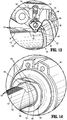
- the proximal portion 512a of the housing 512 defines a counterbore 512c ( FIG.
- proximal face 512d defines a bore or opening 512d' extending through the distal portion 512b of the housing 512 that is configured to slidably receive the elongated shaft 520 therein, as will be described in further detail hereinbelow.
- An exterior surface 512e of the housing 512 defines a pair of opposed transverse through-holes 512f configured to fixedly receive the pair of pins 518 using any suitable means, such as interference fit, friction fit, adhesives, welding, or the like.
- the hub 516 of the housing assembly 510 defines a proximal portion 516a and a distal portion 516b ( FIG. 32B ) and is configured to be slidably received within the counterbore 512c of the housing 512.
- the hub 516 defines an external profile similar to a profile of the counterbore 512c of the housing 512, although it is contemplated that the hub 516 may define any suitable profile capable of being slidably received within the counterbore 512c.
- the proximal and distal portions 516a, 516b of the hub 516 define a through-hole 516c that extends therethrough and is configured to receive the elongated shaft 520 therein.
- the proximal portion 516a of the hub 516 defines a chamfer or bevel 516d configured to abut a corresponding flare 522 defined on a proximal portion of the elongated shaft 520, as will be described in further detail hereinbelow.
- An outer surface 516e of the hub 516 defines a pair of transverse, longitudinally extending, channels or slots 516f at a medial portion thereof that extends longitudinally therealong.
- the transverse channels 516f of the hub 516 are configured to slidably receive the pair of pins 518 in order to prevent rotation of the hub 516 with respect to the housing housing 512, as will be described in further detail hereinbelow.
- the transverse channels 516f of the hub 516 are configured to permit the hub 516 to translate in a proximal or distal direction with the counterbore 512c of the housing 512. In this manner, the transverse channels 516f act as a travel limiter for the hub 516, such that the pair of pins 518 abuts a proximal or distal portion of the transverse channels 516f to inhibit further movement in a proximal or distal direction.
- the biasing element 514 of the housing assembly 510 is interposed between the proximal face 512d of the housing 512 and the distal portion 516b of the hub 516 and is concentrically disposed about the elongated shaft 520 ( e.g., the elongate shaft 520 passes through the biasing element 514).
- the biasing element 514 may be any suitable biasing element or elements capable of being concentrically disposed over the elongated shaft 520, such as one or more Belleville washers, one or more curved disc springs, one or more wave washers, hydraulic, pneumatic, or the like.
- the biasing element 514 biases the hub 516 in a proximal direction to ensure that the bevel 516d of the hub 516 remains in contact with the flare 522 of the elongated shaft 520 and provides a biasing force against distal movement of the hub 516 and the elongated shaft 520.
- the biasing element 514 includes a biasing force (e.g., predetermined spring constant) sufficient to enable the first and second jaw members 560a, 560b to fully close and form a surgical clip, as will be described in further detail hereinbelow.
- the biasing element 514 includes a predetermined spring constant that is greater than the force required to close, fire, or form a surgical clip, but is sufficiently small to allow the biasing element to compress before the pair of jaws 560a, 560b become damaged or deformed, as will be described in further detail hereinbelow.
- endoscopic assembly 500 is utilized in a similar manner to that of endoscopic assembly 400, and therefore, for purposes of brevity, only the differences therebetween will be described in detail hereinbelow.
- the trigger 122 of the trigger assembly 120 is initially squeezed and the drive bar 132 is urged in a distal direction, an inner shaft 531 of the elongated shaft 520 is translated distally such that a surgical clip (not shown) is loaded between the first and second jaw members 560a, 560b.
- the first and second jaw members 560a, 560b are transitioned from an open position to a closed or approximated position to form the surgical clip about the tissue.
- closure of the jaws over large, thick, or dense tissue, or over a separate surgical clip may prevent closure of the first and second jaw members 560a, 560b, and therefore, inhibit the trigger 122 from returning to its original, un-actuated position. In this instance, the first and second jaw members 560a, 560b are also prevented from returning to an un-actuated position, thereby inhibiting the closure of any further surgical clips.
- Continued actuation of the trigger 122 causes an increasing amount of force to be translated along the inner shaft 531 of the elongated shaft 520, and ultimately, to the first and second jaw members 560a, 560b that are rotatably disposed on the elongated shaft 520.
- the increasing force applied to the first and second jaw members 560a, 560b may cause the first and second jaw members 560a, 560b to become deformed or otherwise damaged.
- the force applied to the first and second jaw members 560a, 560b by the inner shaft 531 is translated to the elongated shaft 520 and biases the elongated shaft 520 in a distal direction (e.g., applies a force to the elongated shaft 520 in distal direction).
- the flare 522 of the elongated shaft abuts the bevel 516d of the hub 516 and acts to compress the biasing element 514.
- the biasing force provided by the biasing element 514 inhibits distal advancement of the hub 516, and therefore, inhibits distal advancement of the elongated shaft 520.
- the trigger 122 increases the force applied to the first and second jaw members 560a, 560b, and therefore, increases the force applied to the hub 516 in a distal direction, which overcomes the predetermined spring constant and causes the biasing element 514 to compress, allowing the hub 516, along with the elongated shaft 520, to be urged in a distal direction, preventing damage to the first and second jaw members 560a, 560b.
- the trigger 122 is permitted to return to the un-actuated position, and the surgical clip applier may be used for form another surgical clip.
- inner shaft 531 may be split into a proximal portion and a distal portion in a similar manner as disclosed above with respect to inner shaft 322.
- the components and operation of this embodiment of inner shaft 531 are similar to that of inner shaft 322, and therefore, for purposes of brevity, a detailed description of the components and operation thereof will not be described in detail hereinbelow.
- endoscopic assemblies including a pair of jaws having a unique and diverse closure stroke length thereof, may be provided for use with handle assembly 100 for ratcheting use or non-ratcheting use, similarly as detailed above with respect to endoscopic assemblies 300, 400, and 500 ( FIGS. 15-21 , 22-28 , and 30-33 , respectively).
- Such a configuration accommodates various different endoscopic assemblies having different configurations and/or different closure stroke lengths while providing a constant actuation stroke length of trigger 122.
- various endoscopic assemblies, constructed in accordance with the principles of the present disclosure may be provided which are also capable of firing or forming or closing surgical clips of various sizes, materials, and configurations, across multiple platforms for multiple different manufactures.
- Surgical instruments such as the clip appliers described herein may also be configured to work with robotic surgical systems and what is commonly referred to as "Telesurgery.”
- Such systems employ various robotic elements to assist the surgeon and allow remote operation (or partial remote operation) of surgical instrumentation.
- Various robotic arms, gears, cams, pulleys, electric and mechanical motors, etc. may be employed for this purpose and may be designed with a robotic surgical system to assist the surgeon during the course of an operation or treatment.
- Such robotic systems may include remotely steerable systems, automatically flexible surgical systems, remotely flexible surgical systems, remotely articulating surgical systems, wireless surgical systems, modular or selectively configurable remotely operated surgical systems, etc.
- the robotic surgical systems may be employed with one or more consoles that are next to the operating theater or located in a remote location.
- one team of surgeons or nurses may prep the patient for surgery and configure the robotic surgical system with one or more of the instruments disclosed herein while another surgeon (or group of surgeons) remotely control the instruments via the robotic surgical system.
- a highly skilled surgeon may perform multiple operations in multiple locations without leaving his/her remote console which can be both economically advantageous and a benefit to the patient or a series of patients.
- the robotic arms of the surgical system are typically coupled to a pair of master handles by a controller.
- the handles can be moved by the surgeon to produce a corresponding movement of the working ends of any type of surgical instrument (e.g., end effectors, graspers, knifes, scissors, etc.) which may complement the use of one or more of the embodiments described herein.
- the movement of the master handles may be scaled so that the working ends have a corresponding movement that is different, smaller or larger, than the movement performed by the operating hands of the surgeon.
- the scale factor or gearing ratio may be adjustable so that the operator can control the resolution of the working ends of the surgical instrument(s).
- the master handles may include various sensors to provide feedback to the surgeon relating to various tissue parameters or conditions, e.g., tissue resistance due to manipulation, cutting or otherwise treating, pressure by the instrument onto the tissue, tissue temperature, tissue impedance, etc. As can be appreciated, such sensors provide the surgeon with enhanced tactile feedback simulating actual operating conditions.
- the master handles may also include a variety of different actuators for delicate tissue manipulation or treatment further enhancing the surgeon's ability to mimic actual operating conditions.
- a medical work station is shown generally as work station 1000 and generally may include a plurality of robot arms 1002, 1003; a control device 1004; and an operating console 1005 coupled with control device 1004.
- Operating console 1005 may include a display device 1006, which may be set up in particular to display three-dimensional images; and manual input devices 1007, 1008, by means of which a person (not shown), for example a surgeon, may be able to telemanipulate robot arms 1002, 1003 in a first operating mode.
- Each of the robot arms 1002, 1003 may include a plurality of members, which are connected through joints, and an attaching device 1009, 1011, to which may be attached, for example, a surgical tool "ST" supporting an end effector 1100, in accordance with any one of several embodiments disclosed herein, as will be described in greater detail below.
- Robot arms 1002, 1003 may be driven by electric drives (not shown) that are connected to control device 1004.
- Control device 1004 e.g., a computer
- Control device 1004 may be set up to activate the drives, in particular by means of a computer program, in such a way that robot arms 1002, 1003, their attaching devices 1009, 1011 and thus the surgical tool (including end effector 1100) execute a desired movement according to a movement defined by means of manual input devices 1007, 1008.
- Control device 1004 may also be set up in such a way that it regulates the movement of robot arms 1002, 1003 and/or of the drives.
- Medical work station 1000 may be configured for use on a patient 1013 lying on a patient table 1012 to be treated in a minimally invasive manner by means of end effector 1100. Medical work station 1000 may also include more than two robot arms 1002, 1003, the additional robot arms likewise being connected to control device 1004 and being telemanipulatable by means of operating console 1005. A medical instrument or surgical tool (including an end effector 1100) may also be attached to the additional robot arm. Medical work station 1000 may include a database 1014, in particular coupled to with control device 1004, in which are stored, for example, pre-operative data from patient/living being 1013 and/or anatomical atlases.
- endoscopic assemblies including a pair of jaws having a unique and diverse closure stroke length thereof
- a drive assembly similar to any of the drive assemblies described herein, for accommodating and adapting the closure stroke length for the pair of jaws thereof to the constant trigger stroke length.
- various endoscopic assemblies constructed in accordance with the principles of the present disclosure, which are also capable of firing or forming or closing surgical clips of various sizes, materials, and configurations, across multiple platforms for multiple different manufactures.
Landscapes
- Health & Medical Sciences (AREA)
- Surgery (AREA)
- Life Sciences & Earth Sciences (AREA)
- Engineering & Computer Science (AREA)
- Molecular Biology (AREA)
- Public Health (AREA)
- Heart & Thoracic Surgery (AREA)
- Medical Informatics (AREA)
- Nuclear Medicine, Radiotherapy & Molecular Imaging (AREA)
- Animal Behavior & Ethology (AREA)
- General Health & Medical Sciences (AREA)
- Biomedical Technology (AREA)
- Veterinary Medicine (AREA)
- Robotics (AREA)
- Reproductive Health (AREA)
- Vascular Medicine (AREA)
- Surgical Instruments (AREA)
- Endoscopes (AREA)
Abstract
Description
- This application claims the benefit of and priority to
U.S. Provisional Patent Application No. 62/474,820 filed March 22, 2017 - The technical field relates to surgical clip appliers. More particularly, the present disclosure relates to endoscopic surgical clip appliers having handle assemblies configured for use with various different endoscopic assemblies.
- Endoscopic surgical staplers and surgical clip appliers are known in the art and are used for a number of distinct and useful surgical procedures. In the case of a laparoscopic surgical procedure, access to the interior of an abdomen is achieved through narrow tubes or cannulas inserted through a small entrance incision in the skin. Minimally invasive procedures performed elsewhere in the body are often generally referred to as endoscopic procedures. Typically, a tube or cannula device is extended into the patient's body through the entrance incision to provide an access port. The port allows the surgeon to insert a number of different surgical instruments therethrough using a trocar and for performing surgical procedures far removed from the incision.
- During a majority of these procedures, the surgeon must often terminate the flow of blood or another fluid through one or more vessels. The surgeon will often use a particular endoscopic surgical clip applier to apply a surgical clip to a blood vessel or another duct to prevent the flow of body fluids therethrough during the procedure.
- Endoscopic surgical clip appliers having various sizes (e.g., diameters), that are configured to apply a variety of diverse surgical clips, are known in the art, and which are capable of applying a single or multiple surgical clips during an entry to the body cavity. Such surgical clips are typically fabricated from a biocompatible material and are usually compressed over a vessel. Once applied to the vessel, the compressed surgical clip terminates the flow of fluid therethrough.
- Endoscopic surgical clip appliers that are able to apply multiple clips in endoscopic or laparoscopic procedures during a single entry into the body cavity are described in commonly-assigned
U.S. Pat. Nos. 5,084,057 and5,100,420 to Green et al. , which are both incorporated by reference in their entirety. Another multiple endoscopic surgical clip applier is disclosed in commonly-assignedU.S. Pat. No. 5,607,436 by Pratt et al. , the contents of which is also hereby incorporated by reference herein in its entirety. These devices are typically, though not necessarily, used during a single surgical procedure.U.S. Pat. No. 5,695,502 to Pier et al. , the disclosure of which is hereby incorporated by reference herein, discloses a resterilizable endoscopic surgical clip applier. The endoscopic surgical clip applier advances and forms multiple clips during a single insertion into the body cavity. This resterilizable endoscopic surgical clip applier is configured to receive and cooperate with an interchangeable clip magazine so as to advance and form multiple clips during a single entry into a body cavity. - During endoscopic or laparoscopic procedures it may be desirable and/or necessary to use different size surgical clips or different configured surgical clips depending on the underlying tissue or vessels to be ligated. In order to reduce overall costs of an endoscopic surgical clip applier, it is desirable for a single endoscopic surgical clip applier to be loadable with and capable of firing different size surgical clips as needed.
- Accordingly, a need exists for endoscopic surgical clip appliers that include handle assemblies configured for use with various different endoscopic assemblies having different clips loaded therein and/or configured for performing various different surgical tasks.
- As detailed herein and shown in the drawing figures, as is traditional when referring to relative positioning on a surgical instrument, the term "proximal" refers to the end of the apparatus or component thereof which is closer to the user and the term "distal" refers to the end of the apparatus or component thereof which is further away from the user. Further, to the extent consistent, any or all of the aspects and features detailed herein may be used in conjunction with any or all of the other aspects and features detailed herein.
- Provided in accordance with aspects of the present disclosure is a reposable surgical clip applier including a shaft assembly having an elongated shaft and a housing assembly disposed about a proximal portion of the elongated shaft. The housing assembly includes a housing and a hub. The housing defines a counterbore and the hub is slidably disposed within the counter bore. The hub defines a throughhole configured to receive the elongate shaft therein and is operably coupled to the elongated shaft. A force applied to the elongated shaft in a distal direction causes the hub to distally advance within the housing.
- The housing assembly may further include a biasing element interposed between the housing and the hub that includes a predetermined spring constant.
- In embodiments, when a force applied to the elongated shaft exceeds the predetermined spring constant the hub may be distally advanced within the housing and compress the biasing element.
- The shaft assembly may further include first and second jaw members pivotably disposed on a distal portion of the elongated shaft that are configured to transition between a first, open position, to a second, approximated position.
- In embodiments, when the first and second jaw members are inhibited from transition to the second, approximated position, the elongated shaft and hub may exert a force on the biasing element that exceeds the predetermined spring constant to distally advance the hub within the housing.
- The reposable surgical clip applier may further include a handle assembly that includes a housing and a trigger rotatably supported on the handle assembly. The trigger is in mechanical communication with the first and second jaw members.
- The hub may be configured to distally advance a predetermined distance to permit the trigger to return to a first, unactuated position, and therefore, permit the first and second jaw members to return to the first, open, position.
- The biasing element may include a predetermined spring constant that is greater than a force required to form a surgical clip disposed within the first and second jaw members.
- The housing may define a pair of transverse through-holes configured to fixedly receive a pair of pins.
- The hub may define a pair of transverse channels configured to slidably receive the pair of pins.
- A proximal portion of the elongated shaft may define a flare configured to abut a chamfer defined on a proximal portion of the hub. The flare is configured to inhibit distal translation of the elongated shaft relative to the hub.
- According to another aspect of the present disclosure, a shaft assembly for use with a reposable surgical clip applier is provided. The shaft assembly includes an elongated shaft and a housing assembly that is disposed on a proximal portion of the elongated shaft. The housing assembly includes a housing and a hub that is operably coupled to the elongated shaft. The housing defines a counterbore and the hub is slidably disposed within the counterbore. The hub defines a throughhole configured to receive the elongated shaft therein. A force applied to the elongated shaft in a distal direction causes the hub to distally advance within the housing.
- The housing assembly may further include a biasing element interposed between the housing and the hub that includes a predetermined spring constant.
- In embodiments, when a force applied to the elongated shaft exceeds the predetermined spring constant the hub may be distally advanced within the housing and compresses the biasing element.
- The shaft assembly may further include first and second jaw members pivotably disposed on a distal portion of the elongated shaft that are configured to transition between a first, open position, to a second, approximated position.
- In embodiments, when the first and second jaws are inhibited from transition to the second, approximated position, the elongated shaft and hub may exert a force on the biasing element that exceeds the predetermined spring constant to distally advance the hub within the housing.
- The biasing element may include a predetermined spring constant that is greater than a force required to form a surgical clip disposed within the first and second jaw members.
- The housing may define a pair of transverse through-holes configured to fixedly retain a pair of pins.
- The hub may define a pair of transverse channels configured to slidably receive the pair of pins.
- A proximal portion of the elongated shaft may define a flare configured to abut a chamfer defined on a proximal portion of the hub. The flare is configured to inhibit distal translation of the elongated shaft relative to the hub.
- Aspects and features of the presently-disclosed endoscopic surgical clip applier are described in detail with reference to the drawing figures wherein like reference numerals identify similar or identical structural elements and:
-
FIG. 1 is a perspective view of the proximal portion of an endoscopic surgical clip applier provided in accordance with the present disclosure including a handle assembly having an endoscopic assembly engaged therewith; -
FIG. 2 is perspective view of the endoscopic surgical clip applier ofFIG. 1 with the endoscopic assembly removed from the handle assembly; -
FIG. 3 is an enlarged, perspective view of the area of detail indicated as "3" inFIG. 2 ; -
FIG. 4 is a transverse, cross-sectional view taken across section line 4-4 inFIG. 3 ; -
FIG. 5 is a transverse, cross-sectional view taken across section line 5-5 inFIG. 3 ; -
FIG. 6 is a transverse, cross-sectional view taken across section line 6-6 inFIG. 1 ; -
FIG. 7 is a longitudinal, cross-sectional view taken across section line 7-7 inFIG. 6 ; -
FIG. 8 is a longitudinal, cross-sectional view of handle assembly ofFIG. 1 ; -
FIG. 9 is an exploded view of the handle assembly ofFIG. 1 ; -
FIG. 10 is a perspective view of the handle assembly ofFIG. 1 with a portion of the housing removed to illustrate the internal components therein; -
FIG. 11 is a perspective view of the internal assemblies of the handle assembly ofFIG. 1 ; -
FIG. 12 is an enlarged, longitudinal, cross-sectional view of the area of detail indicated as "12" inFIG. 8 ; -
FIG. 13 is an enlarged, perspective view of the area of detail indicated as "13" inFIG. 10 ; -
FIG. 14 is an enlarged, perspective view of the area of detail indicated as "14" inFIG. 11 ; -
FIG. 15 is a perspective view of another endoscopic assembly configured for use with the handle assembly ofFIG. 1 ; -
FIG. 16 is an enlarged, perspective view of the distal portion of the endoscopic assembly ofFIG. 15 ; -
FIG. 17 is an enlarged, perspective view of the proximal portion of the endoscopic assembly ofFIG. 15 ; -
FIG. 18 is an enlarged, perspective, of the proximal portion of the endoscopic assembly ofFIG. 15 with a portion of the outer housing shown in phantom to illustrate the internal components therein; -
FIG. 19 is a longitudinal, cross-sectional view of the endoscopic assembly ofFIG. 15 ; -
FIG. 20 is an enlarged, longitudinal, cross-sectional view of the proximal portion of the endoscopic assembly ofFIG. 15 ; -
FIG. 21 is an enlarged, longitudinal, cross-sectional view illustrating the operable engagement between the handle assembly ofFIG. 1 and the endoscopic assembly ofFIG. 15 ; -
FIG. 22 is a perspective view of another endoscopic assembly configured for use with the handle assembly ofFIG. 1 ; -
FIG. 23 is an enlarged, perspective view of the distal portion of the endoscopic assembly ofFIG. 22 ; -
FIG. 24 is an enlarged, perspective view of the proximal portion of the endoscopic assembly ofFIG. 22 ; -
FIG. 25 is an enlarged, perspective, of the proximal portion of the endoscopic assembly ofFIG. 22 with a portion of the outer housing shown in phantom to illustrate the internal components therein; -
FIG. 26 is a longitudinal, cross-sectional view of the endoscopic assembly ofFIG. 22 ; -
FIG. 27 is a longitudinal, cross-sectional view of the proximal portion of the endoscopic assembly ofFIG. 22 ; -
FIG. 28 is an enlarged, longitudinal, cross-sectional view illustrating the operable engagement between the handle assembly ofFIG. 1 and the endoscopic assembly ofFIG. 22 ; -
FIG. 29 is a top, cross-sectional view illustrating an alternate embodiment of an endoscopic assembly provided in accordance with the present disclosure; -
FIG. 30 is a perspective view of yet another embodiment of an endoscopic assembly provided in accordance with the present disclosure; -
FIG. 31 is a cross-sectional view of the endoscopic assembly ofFIG. 30 , taken along section line 31-31; -
FIG. 32 is an enlarged view of the area of detail indicated inFIG. 31 ; -
FIG. 32A is a side, cross-sectional view, of a housing of the endoscopic assembly ofFIG. 30 ; -
FIG. 32B is a side, cross-sectional view, of a hub of the endoscopic assembly ofFIG. 30 ; -
FIG. 33 is an rear, perspective view, of the endoscopic assembly ofFIG. 30 illustrated with the housing removed; and -
FIG. 34 is a schematic illustration of a robotic surgical system configured for use in accordance with the present disclosure. - Turning to
FIGS. 1 and2 , an endoscopic surgical clip applier provided in accordance with the present disclosure is identified byreference numeral 10.Surgical clip applier 10 generally includes ahandle assembly 100 and a plurality ofendoscopic assemblies 200 selectively connectable to and extendable distally fromhandle assembly 100.Handle assembly 100 is advantageously configured to operate each of the plurality ofendoscopic assemblies 200, upon connection thereto, and may be configured as a sterilizable, reusable component such that handleassembly 100 may be repeatedly used with different and/or additionalendoscopic assemblies 200 during the course of one or more surgical procedures. Theendoscopic assemblies 200 may be configured as single-use disposable components, limited-use disposable components, or reusable components, depending upon a particular purpose and/or the configuration of the particularendoscopic assembly 200. In either configuration, the need formultiple handle assemblies 100 is obviated and, instead, the surgeon need only select an appropriateendoscopic assembly 200 and connect thatendoscopic assembly 200 to handleassembly 100 in preparation for use. -
Handle assembly 100 is initially detailed for use in connection with a genericendoscopic assembly 200 that includes features common to any endoscopic assembly usable withhandle assembly 100. Exemplary embodiments of particular endoscopic assemblies, e.g., endoscopic assembly 300 (FIG. 15 ) and endoscopic assembly 400 (FIG. 22 ), are thereafter detailed below. Endoscopic assembly 300 (FIG. 15 ), for example, is configured for grasping and manipulating tissue, retrieving a surgical clip, and firing and forming the surgical clip about tissue. Endoscopic assembly 400 (FIG. 22 ), as another example, includes at least one surgical clip loaded therein and is configured to sequentially fire and form the at least one surgical clip about tissue. It is also envisioned that various other endoscopic assemblies for performing various different surgical tasks and/or having various different configurations may be provided for use withhandle assembly 100. - Continuing with reference to
FIGS. 1 and2 , as noted above,endoscopic assembly 200 is configured to selectively connect to and extend distally fromhandle assembly 100.Endoscopic assembly 200 includes aproximal hub 210 configured for insertion into and releasable engagement withinhandle assembly 100, anelongated shaft 220 extending distally fromproximal hub 210, and an end effector assembly (not shown) disposed at the distal end ofelongated shaft 220. Internal drive components (not shown) extend throughproximal hub 210 andelongated shaft 220 so as to operably couple the end effector assembly (not shown) withhandle assembly 100 upon engagement ofendoscopic assembly 200 withhandle assembly 100, e.g., to enable performing the one or more surgical tasks of theendoscopic assembly 200.Proximal hub 210 defines a generally tubular configuration and includes a longitudinally-extendingslot 212 defined therein and anannular groove 214 defined therein. Longitudinally-extendingslot 212 defines an open proximal end 213.Annular groove 214 extends circumferentially aboutproximal hub 210 and intersects longitudinally-extendingslot 212, although other non-intersecting configurations are also contemplated. - Referring additionally to
FIGS. 3-5 , handleassembly 100 includes areceiver assembly 170 configured to receiveproximal hub 210 ofendoscopic assembly 200 and enable releasable engagement ofendoscopic assembly 200 withhandle assembly 100.Receiver assembly 170 includes anouter collar 172 and an innertubular member 174. Innertubular member 174 defines an interior diameter slightly larger than an exterior diameter ofproximal hub 210 ofendoscopic assembly 200 to enable slidable insertion ofproximal hub 210 into innertubular member 174 without significant play therebetween. Innertubular member 174 further includes a plurality ofapertures 176 defined therethrough and positioned circumferentially about innertubular member 174.Apertures 176 define reducedinterior openings 177a as comparted to theexterior openings 177b thereof. Aball bearing 178 is disposed within each of theapertures 176. Although a portion of eachball bearing 178 protrudes inwardly through the reducedinterior opening 177a of itsrespective aperture 176, the reducedinterior openings 177a inhibitball bearings 178 from passing entirely therethrough.Outer collar 172 is positioned so as to block theexterior openings 177b of apertures, thereby retainingball bearings 178 withinapertures 176 betweenouter collar 172 and the reducedinterior openings 177a (except for the portions ofball bearings 178 extending through the reducedinterior openings 177a). - A
pin 180 extends through apin aperture 182 defined within innertubular member 174 and at least partially through apin slot 184 defined withinouter collar 172.Pin 180 extends at least partially into the interior of innertubular member 174 and, as detailed below, is configured to facilitate alignment ofendoscopic assembly 200 upon insertion ofendoscopic assembly 200 intohandle assembly 100.Pin 180 is further configured to retainouter collar 172 and innertubular member 174 in fixed rotational orientation relative to one another.Outer collar 172 is engaged withrotation knob 190 ofhandle assembly 100 in fixed rotational orientation such that, withpin 180 rotatably couplingouter collar 172 and innertubular member 174, rotation ofrotation knob 190 can be effected to similarly rotatereceiver assembly 170.Rotation knob 190 includes analignment indicator 192 disposed thereon that is aligned withpin 180 to enable alignment ofendoscopic assembly 200 withreceiver assembly 170 without the need to directly view the position ofpin 180. - With reference to
FIGS. 1 ,2 ,6 and 7 , in order to engageendoscopic assembly 200 withhandle assembly 100,endoscopic assembly 200 is oriented such that longitudinally-extendingslot 212 thereof is aligned withpin 180 ofreceiver assembly 170. As noted above, rather than having to viewpin 180 directly, alignment of longitudinally-extendingslot 212 and pin 180 can be achieved via aligning longitudinally-extendingslot 212 withalignment indicator 192 ofrotation knob 190 ofhandle assembly 100. Once alignment has been achieved,proximal hub 210 ofendoscopic assembly 200 is slid proximally into innertubular member 174 ofreceiver assembly 170. Alignment of longitudinally-extendingslot 212 andpin 180 ensures that, upon proximal sliding ofproximal hub 210 into innertubular member 174,pin 180 is translated through longitudinally-extendingslot 212. - As
proximal hub 210 is slid proximally into innertubular member 174,ball bearings 178 apply radially-inward force on the exterior ofproximal hub 210 causingproximal hub 210,outer collar 172, innertubular member 174, and/orball bearings 178 to move or flex to accommodateproximal hub 210 betweenball bearings 178.Ball bearings 178 are permitted to rotate withinapertures 176 asproximal hub 210 is slid proximally into innertubular member 174, reducing friction and permitting relatively easy sliding ofproximal hub 210 into innertubular member 174. Upon full insertion ofproximal hub 210 into innertubular member 174, e.g., uponpin 180 reaching the closed, distal end of longitudinally-extendingslot 212,ball bearings 178 are moved into position aboutannular groove 214. As a result of the radially-inward force imparted byball bearings 178, once the fully inserted position has been achieved,ball bearings 178 are urged intoannular groove 214 to thereby releasably lockproximal hub 210 ofendoscopic assembly 200 in engagement withinreceiver assembly 170 ofhandle assembly 100. The operable coupling ofendoscopic assembly 200 withhandle assembly 100 to enable operation thereof to perform one or more surgical tasks depends upon the type ofendoscopic assembly 200 engaged withhandle assembly 100 and will be detailed below with respect to exemplary endoscopic assemblies 300 (FIG. 15 ) and 400 (FIG. 22 ). - In order to remove
endoscopic assembly 200 fromhandle assembly 100,endoscopic assembly 200 is pulled distally relative to handleassembly 100 under sufficient urging so as to dislodgeball bearings 178 fromannular groove 214, thus permittingproximal hub 210 ofendoscopic assembly 200 to be slid distally out ofreceiver assembly 170 ofhandle assembly 100. - Referring to
FIGS. 1 ,2 , and8-10 ,handle assembly 100 generally includes ahousing 110, atrigger assembly 120 pivotably coupled tohousing 110, a ratchetingdrive assembly 130 operably coupled to triggerassembly 120, abypass assembly 150 operably coupled to ratchetingdrive assembly 130,receiver assembly 170 which extends distally fromhousing 110, androtation knob 190 which is operably disposed aboutreceiver assembly 170. -
Housing 110 defines abody portion 111 and a fixedhandle portion 112 extending downwardly frombody portion 111.Housing 110 is formed from first andsecond housing components second housing components Housing 110 is configured to house the internal working components ofhandle assembly 100.Body portion 111 includes adistal nose 114 defining anannular slot 115 on the interior thereof. More specifically, first andsecond housing components second housing components housing 110,annular slot 115 is formed.Receiver assembly 170 ofhandle assembly 100 includes aretention clip 186 disposed about the proximal end of innertubular member 174 thereof.Retention clip 186 is captured withinannular slot 115 defined withindistal nose 114 ofhousing 110, e.g., upon engagement of first andsecond housing components Retention clip 186 is captured withinannular slot 115 to rotatably engagereceiver assembly 170 withhousing 110.Rotation knob 190 ofhandle assembly 100 is operably engaged aboutreceiver assembly 170, e.g., viaouter collar 172, biasingmember 194, and elastomeric C-ring 196, in fixed rotational orientation relative thereto such that rotation ofrotation knob 190 relative tohousing 110 effects similar rotation ofreceiver assembly 170 relative tohousing 110. Thus, withendoscopic assembly 200 engaged withinreceiver assembly 170,rotation knob 190 may be rotated relative tohousing 100 to similarly rotateendoscopic assembly 200 relative tohousing 110. -
Body portion 111 ofhousing 110 further incudes aninternal pivot post 116 extending transversely betweenhousing components guide track 117 defined within one or both ofhousing components handle portion 112 ofhousing 110 is configured to facilitate grasping ofhandle assembly 100 and manipulation thereof and is monolithically formed withbody portion 111, although other configurations are also contemplated. - With additional reference to
FIG. 11 ,trigger assembly 120 generally includes atrigger 122, a biasingmember 127, and alinkage 128.Trigger 122 includes a graspingportion 123, anintermediate pivot portion 124, and aproximal extension portion 125. Graspingportion 123 oftrigger 122 extend downwardly frombody portion 111 ofhousing 110 in opposed relation relative to fixedhandle portion 112 ofhousing 110. Graspingportion 123 is configured to facilitate grasping and manipulation oftrigger 122.Intermediate pivot portion 124 oftrigger 122 is at least partially disposed withinhousing 110 and defines apivot aperture 126a that is configured to receivepivot post 116 ofhousing 110 so as to enable pivoting oftrigger 122 aboutpivot post 116 and relative tohousing 110, e.g., between an un-actuated position, wherein graspingportion 123 oftrigger 122 is spaced-apart relative to fixedhandle portion 112, and an actuated position, wherein graspingportion 123 oftrigger 122 is approximated relative to fixedhandle portion 112. -
Proximal extension portion 125 oftrigger 122 oftrigger assembly 120 is disposed on an opposite side ofintermediate pivot portion 124 and, thus,pivot post 116, as compared to graspingportion 123 oftrigger 122. As such, pivoting of graspingportion 123 proximally, e.g., towards the actuated position, urgesproximal extension portion 125 distally.Proximal extension portion 125 includes afirst aperture 126b configured to receive a first end of biasingmember 127, and a pair ofsecond apertures 126c configured to receive afirst pin 129a for pivotably coupling the proximal end oflinkage 128 andproximal extension portion 125 oftrigger 122 with each other. The second end of biasingmember 127 is engaged about anarm 118 extending transversely within fixedhandle portion 112.Biasing member 127 is disposed in an at-rest condition in the un-actuated position of graspingportion 123 oftrigger 122. Pivoting of graspingportion 123 towards the actuated position elongates biasingmember 127 storing energy therein such that, upon release of graspingportion 123, graspingportion 123 is returned towards the un-actuated position under the bias of biasingmember 127. Although illustrated as an extension coil spring, biasingmember 127 may define any suitable configuration for biasinggrasping portion 123 oftrigger 122 towards the un-actuated position. - As noted above,
linkage 128 is coupled at its proximal end toproximal extension portion 125 oftrigger 122 viafirst pin 129a.Linkage 128 is also pivotably coupled, at its distal end, toproximal extension 134 ofdrive bar 132 of ratchetingdrive assembly 130 via asecond pin 129b.Second pin 129b extends outwardly from either or both sides ofproximal extension 134 ofdrive bar 132 and is received within the longitudinally-extending guide track(s) 117 defined withinhousing component 113a and/orhousing component 113b. As a result of this configuration, pivoting of graspingportion 123 towards the actuated position urgesproximal extension portion 125 distally which, in turn, urgeslinkage 128 distally such thatsecond pin 129b is translated distally through longitudinally-extending guide track(s) 117. - Continuing with reference to
FIGS. 1 ,2 , and8-11 , ratchetingdrive assembly 130 ofhandle assembly 100 includes adrive bar 132 and apawl assembly 140.Drive bar 132 includes aproximal extension 134, aratchet rack 136, and distal andproximal recesses Proximal extension 134 is disposed at the proximal end of thedrive bar 132 and defines anaperture 135 configured to receivesecond pin 129b oftrigger assembly 120 so as to pivotably couple the distal end oflinkage 128 and drivebar 132 with one another, as noted above. As such, upon pivoting of graspingportion 123 towards the actuated position to urgesecond pin 129b distally through longitudinally-extending guide track(s) 117,drive bar 132 is translated distally throughbody portion 111 ofhousing 110.Ratchet rack 136 ofdrive bar 132 defines a plurality ofteeth 137 and extends longitudinally alongdrive bar 132 on an upper surface thereof. Distal andproximal recesses drive bar 132 and are positioned distallyadjacent ratchet rack 136 and proximallyadjacent ratchet rack 136, respectively. - Referring also to
FIG. 12 ,pawl assembly 140 of ratchetingdrive assembly 130 includes aratchet pawl 142, apawl pin 144, and apawl biasing member 146.Ratchet pawl 142 is pivotably coupled tobody portion 111 ofhousing 110 bypawl pin 144 so as to enable operable engagement ofratchet pawl 142 withratchet rack 136 when anendoscopic assembly 200 that uses the ratcheting function is connected to handleassembly 100, and to enable pivoting ofratchet pawl 142 to a bypass position when aendoscopic assembly 200 that does not use the ratcheting function is connected to handleassembly 100.Ratchet pawl 142 further includes a pair of outwardly-extendingtabs 143 extending transversely from either side thereof, the importance of which are detailed below. -
Pawl biasing member 146 ofpawl assembly 140 is coupled betweenratchet pawl 142 andbody portion 111 ofhousing 110 so as to biasratchet pawl 142 towards a use position and away from the bypass position. In the use position, ratchetpawl 142 is oriented to operably engageratchet rack 136 upon distal advancement ofdrive bar 132. However, in the proximal-most position ofdrive bar 132, corresponding to the un-actuated position oftrigger 122, ratchetpawl 142 is disposed at least partially withindistal recess 138 ofdrive bar 132. Accordingly, at least initially, ratchetpawl 142 is disengaged fromratchet rack 136. - With reference to
FIGS. 8-14 ,bypass assembly 150 is operably positioned betweenpawl assembly 140 andreceiver assembly 170 and is configured, in response to engagement ofhandle assembly 100 with anendoscopic assembly 200 that does not use the ratcheting function, to pivotratchet pawl 142 to the bypass position, thereby inhibiting ratcheting upon advancement ofdrive bar 132. When anendoscopic assembly 200 that uses the ratcheting function is connected to handleassembly 100,bypass assembly 150 remains idle such thatratchet pawl 142 remains in the use position to enable ratcheting ofratchet pawl 142 alongratchet rack 136 upon advancement ofdrive bar 132. -
Bypass assembly 150 includes asleeve 152, a biasingmember 154, and acamming clip 156.Sleeve 152 extends into the proximal end of innertubular member 174 ofreceiver assembly 170 and is disposed about the distal end ofdrive bar 132 ofdrive assembly 130 in slidable relation relative to both innertubular member 174 and drivebar 132.Biasing member 154 is disposed within innertubular member 174 ofreceiver assembly 170 and aboutsleeve 152. More specifically, biasingmember 154 is retained aboutsleeve 152 between adistal rim 153 ofsleeve 152 and anannular shoulder 179 defined within the interior of innertubular member 174 at the proximal end thereof. As a result of this configuration, biasingmember 154biases sleeve 152 proximally into the interior of innertubular member 174.Distal rim 153 ofsleeve 152 is radially-spaced from the interior wall defining innertubular member 174 so as to define an annular spacing "A1" therebetween.Sleeve 152 further defines an internal diameter "D1." -
Camming clip 156 ofbypass assembly 150 is engaged within anannular groove 157 defined about the exterior ofsleeve 152 towards the proximal end thereof.Camming clip 156 is sufficiently dimensioned so as to inhibit passage into the interior of innertubular member 174 and, thus, inhibitssleeve 152 from fully entering innertubular member 174 under the bias of biasingmember 154.Camming clip 156 further include a pair of opposed, inwardly extendingfingers 158 at the free ends thereof.Fingers 158 are positioned such that, upon sufficient proximal urging ofsleeve 152 against the bias of biasingmember 154,fingers 158 contactrespective tabs 143 ofratchet pawl 142. Thus, upon further proximal movement ofsleeve 152,fingers 158 urgerespective tabs 143 proximally, ultimately such thatratchet pawl 142 is urged to rotate aboutpawl pin 144 and against the bias ofpawl biasing member 146 from the use position to the bypass position. - Turning to
FIGS. 15-21 , andendoscopic assembly 300 provided in accordance with the present disclosure and configured for use withhandle assembly 100 is shown.Endoscopic assembly 300 is configured for non-ratcheting use and, thus, upon engagement ofendoscopic assembly 300 withhandle assembly 100, as detailed below, ratchetpawl 142 is pivoted to and retained in the bypass position, thus enabling such non-ratcheting use.Endoscopic assembly 300 generally includes aproximal hub 310, aninner drive assembly 320 disposed within and extending throughproximal hub 310, anelongated shaft 340 extending distally fromproximal hub 310, and anend effector assembly 350 including a pair ofjaw members elongated shaft 340.Endoscopic assembly 300 is configured to grasp and/or manipulate tissue, retrieve a surgical clip, and to close, fire, or form the surgical clip about tissue. It is contemplated thatendoscopic assembly 300 be configured to close, fire or form surgical clips similar to those shown and described inU.S. Patent No. 4,834,096 , the entire contents of which are incorporated herein by reference. - With additional reference to
FIGS. 1 ,2 ,6, and 7 ,proximal hub 310 ofendoscopic assembly 300 defines a generally tubular configuration and an exterior diameter slightly smaller than that of innertubular member 174 ofreceiver assembly 170 ofhandle assembly 100 to enable slidable insertion ofproximal hub 310 into innertubular member 174 without significant play therebetween.Proximal hub 310 further includes features similar to those detailed above with respect toendoscopic assembly 200 so as to enable engagement ofproximal hub 310 withinreceiver assembly 170 ofhandle assembly 100 in a similar fashion. More specifically, proximal hub 310 a longitudinally-extendingslot 311 configured to receivepin 180 ofreceiver assembly 170 to ensure proper alignment ofendoscopic assembly 300 relative to handleassembly 100, and anannular groove 312 configured to receive at least a portion of eachball bearing 178 to releasably lockproximal hub 310 ofendoscopic assembly 300 in engagement withinreceiver assembly 170 ofhandle assembly 100. - Referring again to
FIGS. 15-21 ,proximal hub 310 ofendoscopic assembly 300 further defines aninternal bore 313 having an openproximal end 314 and a reduced-diameter distal opening as compared to the diameter ofbore 313 so as to define ashoulder 315 therebetween. Aferrule 316 is seated within the open proximal end ofproximal hub 310 and secured therein in any suitable fashion, e.g., welding, gluing, press-fitting, mechanical engagement, etc. -
Ferrule 316 ofproximal hub 310 defines anaperture 317 extending longitudinally therethrough and a proximally-facingsurface 318 surroundingaperture 317 such that proximally-facingsurface 318 defines a ring-shaped configuration.Aperture 317 is disposed in communication with the interior ofproximal hub 310 so as to provide access toinner drive assembly 320, as detailed below, and defines a diameter "D2" that is sufficiently large so as to permit slidable insertion ofdrive bar 132 of ratchetingdrive assembly 130 ofhandle assembly 100 therethrough. However, diameter "D2" ofaperture 317 is smaller than internal diameter "D1" ofsleeve 152. Proximally-facingsurface 318 offerrule 316 defines an annular width "A2" that is larger than the annular spacing "A1" defined betweendistal rim 153 ofsleeve 152 and the interior wall defining innertubular member 174. As a result of diameter "D2" being smaller than diameter "D1" and annular width "A2" being larger than annular spacing "A1,"proximal hub 310 is inhibited from passing into the interior ofsleeve 152 and is likewise inhibited from passing about the exterior ofsleeve 152. Rather, upon proximal urging ofproximal hub 310 ofendoscopic assembly 300 into innertubular member 174 ofreceiver assembly 170 ofhandle assembly 100, e.g., to engageendoscopic assembly 300 withhandle assembly 100, proximally-facingsurface 318 offerrule 316 eventually contactsdistal rim 153 ofsleeve 152 such that further proximal urging ofproximal hub 310 into innertubular member 174 urgessleeve 152 proximally against the bias of biasingmember 154. - As noted above,
endoscopic assembly 300 is configured for non-ratcheting use. Accordingly, the above-detailed configuration regarding the relative dimensions of the components ofproximal hub 310 and those ofbypass assembly 150 ensures thatproximal hub 310 urgesratchet pawl 142 from the use position to the bypass position upon engagement ofendoscopic assembly 300 withhandle assembly 100, thus disabling the ratcheting components of ratchetingdrive assembly 130. More specifically, withpin 180 received within longitudinally-extendingslot 311 andproximal hub 310 sliding proximally into innertubular member 174 ofreceiver assembly 170, but prior to engagement ofball bearings 178 withinannular groove 312, proximally-facingsurface 318 offerrule 316 contactsdistal rim 153 ofsleeve 152 and urgessleeve 152 proximally such thatfingers 158 ofcamming clip 156urge tabs 143 ofratchet pawl 142 proximally to thereby rotateratchet pawl 142 aboutpawl pin 144 from the use position towards the bypass position. Accordingly, upon reaching the engaged position ofproximal hub 310 within innertubular member 174, e.g., upon engagement ofball bearings 178 withinannular groove 312, as shown inFIG. 21 ,ferrule 316 has urgedsleeve 152 to a proximal-most position whereinratchet pawl 142 is pivoted to and retained in the bypass position. Thus, whenendoscopic assembly 300 is engaged withhandle assembly 100, ratcheting of ratchetingdrive assembly 130 is disabled. - Referring still to
FIGS. 15-21 ,inner drive assembly 320 ofendoscopic assembly 300 includes aninner shaft 322 slidably disposed within bothproximal hub 310 andelongated shaft 340 ofendoscopic assembly 300.Inner shaft 322 includes aproximal end 323 supporting atransverse pin 324 disposed withinbore 313 ofproximal hub 310, and adistal end 325 supporting acam pin 326 disposed towards thedistal end 344 ofelongated shaft 340. As detailed below,cam pin 326 is disposed within cam slots (not shown) ofjaw members end effector assembly 350 to enable pivoting ofjaw members inner shaft 322 throughelongated shaft 340. -
Inner drive assembly 320 further includes aplunger 328 and first andsecond biasing members Plunger 328 is slidably disposed withinbore 313 ofproximal hub 310 and is retained therein betweenshoulder 315 andferrule 316.Plunger 328 defines aninternal cavity 329 within whichtransverse pin 324 ofproximal end 323 ofinner shaft 322 is slidably confined. - First biasing
member 330 ofinner drive assembly 320 is disposed withininternal bore 313 ofproximal hub 310 and interposed betweenshoulder 315 ofproximal hub 310 andtransverse pin 324 ofinner shaft 322. First biasingmember 330 has a first spring constant "K1" which is less than a second spring constant "K2" ofsecond biasing member 332, the importance of which is detailed below. Second biasingmember 332 is disposed withincavity 329 ofplunger 328 and is interdisposed betweentransverse pin 324 ofinner shaft 322 and the proximal end ofplunger 328. As detailed below, first andsecond biasing members inner shaft 322 throughproximal hub 310 andelongated shaft 340 to open and close jaw members 340a, 340b, and to enable full actuation of trigger 122 (FIG. 1 ), as detailed below. -
Elongated shaft 340 ofendoscopic assembly 300 defines a generally tubular configuration and extends between and interconnectsproximal hub 310 and endeffector assembly 350. More specifically, theproximal end 342 ofelongated shaft 340 is secured toproximal hub 310, while thedistal end 344 ofelongated shaft 340 supports aclevis 346 configured to pivotably engagejaw members end effector assembly 350 atdistal end 344 ofelongated shaft 340 via apivot pin 352. -
End effector assembly 350, as noted above, includes first andsecond jaw members Jaw members clevis 346 viapivot pin 352 so as to permit pivoting ofjaw members elongated shaft 340 between an open position and a closed position. Eachjaw member proximal end distal end proximal end jaw member cam pin 326 ofinner shaft 322 such that translation ofinner shaft 322 pivotsjaw members jaw members U.S. Patent No. 4,834,096 , previously incorporated herein by reference. - Referring momentarily to
FIG. 29 , an alternate embodiment ofinner drive assembly 320 is illustrated. In this embodiment,inner shaft 322 ofendoscopic assembly 300 is divided into a proximal portion 322' and adistal portion 322". Aproximal end 322a" ofdistal portion 322" includes abore 322b" defined therein configured to slidably receive anelongate member 322b' disposed on adistal end 322a' of proximal portion 322'. Atransverse slot 322c" is defined throughdistal portion 322" ofinner shaft 322 and is configured to slidably retain atransverse pin 320a'.Transverse pin 320a' is fixedly retained within an aperture (not shown) defined in thedistal end 322a' of proximal portion 322' using any suitable means, such as friction fit, welding, adhesives, or the like. A biasingmember 320b' is disposed between proximal portion 322' anddistal portion 322" ofinner shaft 322 and acts uponproximal end 322a" ofdistal portion 322" and anannular surface 322c' disposed on adistal end 322a' of proximal portion 322'. In this manner, biasing member (e.g., a spring or the like) 320b' is initially compressed such that proximal portion 322' anddistal portion 322" are maintained in spaced relation.Transverse pin 320a' inhibits proximal portion 322' anddistal portion 322" from being urged apart by biasingmember 320b' astransverse pin 320b' is at a proximal most position in the stroke oftransverse slot 322c". - In operation, if the closure of the
jaw members jaw members drive assembly 130 ofhandle assembly 100 may be fully completed (wherein a distal driving force of proximal portion 322' ofinner shaft 322 axiallycompresses biasing member 320b' having a spring constant "K3", which is greater than that of "K1" or "K2") in order to permit a re-set or a reversal of ratchetingdrive assembly 130 andpermit trigger 122 to open. - The use of
handle assembly 100 in conjunction withendoscopic assembly 300 is now detailed with reference toFIGS. 8-21 . Initially,endoscopic assembly 300 is engaged withhandle assembly 100, as detailed above. Such engagement ofendoscopic assembly 300 withhandle assembly 100, as also detailed above, effects pivoting ofratchet pawl 142 to and retention ofratchet pawl 142 in the bypass position. Onceendoscopic assembly 300 and handleassembly 100 are engaged withratchet pawl 142 in the bypass position, handleassembly 100 andendoscopic assembly 300 are together ready for use. - In use,
trigger 122 is initially disposed in the un-actuated position under the bias of biasingmember 127. Withtrigger 122 disposed in the un-actuated position, drivebar 132 is disposed in a proximal-most position. Further,inner shaft 322 is disposed in a proximal-most position under the bias of first andsecond biasing members jaw members jaw members jaw members Jaw members end effector assembly 350 may be used to retrieve or pick-up a surgical clip from a clip holder (not shown), the surgical clip may be manually loaded by the user,end effector assembly 350 may be pre-loaded by the manufacturer, or the surgical clip may be placed betweenjaw members - In or to close, fire, or form the surgical clip loaded between
jaw members trigger 122 is urged from the un-actuated position to the actuated position. More specifically, graspingportion 123 oftrigger 122 is pivoted towards fixedhandle portion 112 ofhousing 110 to urgelinkage 128 distally which, in turn, urges drivebar 132 distally throughhousing 110,receiver assembly 170, and intobore 313 ofproximal hub 310 ofendoscopic assembly 300. Astrigger 122 is pivoted further towards the actuated position, drivebar 132 eventually contacts plunger 328 ofdrive assembly 320 ofendoscopic assembly 300. Due to first spring constant "K1" of first biasingmember 330 being less than second spring constant "K2" ofsecond biasing member 332, asdrive bar 132 is initially urged intoplunger 328,plunger 328 andinner shaft 322 translate together distally such that first biasingmember 330 is compressed while second biasingmember 332 remains substantially un-compressed. - As
inner shaft 322 is translated distally,cam pin 326 is translated through the cam slots ofjaw members jaw members end effector assembly 350.Cam pin 326 is advanced distally untilcam pin 326 reaches an end of the cam slots ofjaw members jaw members inner shaft 322 to fully form the surgical clip may vary. As the distance of travel fortrigger 122 between the un-actuated and actuated positions does not vary, it isendoscopic assembly 300 that accounts for this variation, as detailed below. - Once
jaw members cam pin 326 has reached the end of the cam slots ofjaw members inner shaft 322 is no longer permitted to travel further distally. Thus, upon further distal urging ofdrive bar 132, e.g., to complete the actuation stroke oftrigger 122,plunger 328 is advanced distally independently ofinner shaft 322 to compresssecond biasing member 332. Thus, the compression ofsecond biasing member 332 enablesinner shaft 322 to remain in position while the full actuation stroke oftrigger 122 is completed. - Once the surgical clip has been fully formed,
trigger 122 may be released and allowed to return under bias to the un-actuated position, thereby pullingdrive bar 132 back to its proximal-most position and allowingjaw members jaw members end effector assembly 350 may be used to grasp and/or manipulate tissue as desired prior to or after formation of one or more surgical clips. - Turning to
FIGS. 22-28 , anotherendoscopic assembly 400 provided in accordance with the present disclosure and configured for use with handle assembly 100 (FIG. 1 ) is shown.Endoscopic assembly 400 is configured for ratcheting use and, thus, upon engagement ofendoscopic assembly 400 withhandle assembly 100, as detailed below, ratchetpawl 142 remains in the use position to enable ratcheting use.Endoscopic assembly 400 generally includes aproximal hub 410, anelongated shaft 420 extending distally fromproximal hub 410, adrive assembly 430 disposed withinproximal hub 410 andelongated shaft 420, and a pair ofjaw members elongated shaft 420.Endoscopic assembly 400 is configured to close, fire, or form one or more surgical clips about tissue. More specifically, it is contemplated thatendoscopic assembly 400 may be configured to close, fire or form surgical clips similar to those shown and described inU.S. Patent Nos. 7,819,886 or7,905,890 , the entire contents of each of which is incorporated herein by reference. - With reference also to
FIGS. 1 ,2 ,6, and 7 ,proximal hub 410 further includes features similar to those detailed above with respect toendoscopic assembly 200 so as to enable engagement ofproximal hub 410 withinreceiver assembly 170 ofhandle assembly 100 in a similar fashion. More specifically, proximal hub 410 a longitudinally-extendingslot 411 configured to receivepin 180 ofreceiver assembly 170 to ensure proper alignment ofendoscopic assembly 400 relative to handleassembly 100, and anannular groove 412 configured to receive at least a portion of eachball bearing 178 to releasably lockproximal hub 410 ofendoscopic assembly 400 in engagement withinreceiver assembly 170 ofhandle assembly 100. - As noted above,
endoscopic assembly 400 is configured for ratcheting use and, thus, upon engagement ofendoscopic assembly 400 withhandle assembly 100ratchet pawl 142 remains in the use position to enable ratcheting use. To allow such,proximal hub 410 defines a ring-shapedaperture 414 annularly disposed between the outer housing definingproximal hub 410 andplunger 435 ofdrive assembly 430, which is slidably disposed withinproximal hub 410. This ring-shapedaperture 414 is positioned and dimensioned to receivedistal rim 153 ofsleeve 152 upon insertion ofendoscopic assembly 400 intoreceiver assembly 170. Thus, upon insertion ofproximal hub 410 ofendoscopic assembly 400 into innertubular member 174 ofreceiver assembly 170 ofhandle assembly 100, e.g., to engageendoscopic assembly 400 withhandle assembly 100,distal rim 153 ofsleeve 152 passes intoproximal hub 410 through ring-shapedaperture 414 undisturbed such thatsleeve 152 is maintained in its distal-most position under the bias of biasingmember 154. Withsleeve 152 in its distal-most position, ratchetpawl 142 remains in the use position, thus enabling ratcheting use of ratchetingdrive assembly 130 ofhandle assembly 100. - Referring back to
FIGS. 22-28 , as mentioned above,endoscopic assembly 400 includes anelongated shaft 420 extending distally fromproximal hub 410.Elongated shaft 420 includes aproximal end 422 secured toproximal hub 410 and adistal end 424 supporting first andsecond jaw members -
Drive assembly 430 includes aninner shaft 431 slidably supported within the interior ofelongated shaft 420 andproximal hub 410.Inner shaft 431 includes aproximal end 433 and adistal end 434. Theproximal end 433 ofinner shaft 431 extends intointernal bore 413 ofproximal hub 410 and is operably coupled toplunger 435 ofdrive assembly 430 via receipt oftransverse pin 436 ofinner shaft 431 withinlongitudinal slots 437 ofplunger 435.Distal end 434 ofinner shaft 431 is configured to transition first andsecond jaw members second jaw members inner shaft 431 throughelongated shaft 420. - It is contemplated that
inner shaft 431 may be split into a proximal portion and a distal portion in a similar manner as disclosed above with respect toinner shaft 322. The components and operation of this embodiment ofinner shaft 431 are similar to that ofinner shaft 322, and therefore, a detailed description of the components and operation thereof will not be described hereinbelow. -
Drive assembly 430 further includes astop ring 438 and first andsecond biasing members inner shaft 431.Stop ring 438 is fixedly engaged aboutinner shaft 431 and disposed withininternal bore 413 ofproximal hub 410. First biasingmember 439a is positioned distally ofstop ring 438 and is retained betweenstop ring 438 and the distal end ofproximal hub 410. Second biasingmember 439b is positioned proximally ofstop ring 438 and is retained betweenstop ring 438 and the distal end ofplunger 435. First biasingmember 439a has a first spring constant "KK1" which is less than a second spring constant "KK2" ofsecond biasing member 439b, the importance of which is detailed below. - The use of
handle assembly 100 in conjunction withendoscopic assembly 400 is now detailed with reference toFIGS. 8-14 and22-28 . Initially,endoscopic assembly 400 is engaged withhandle assembly 100, as detailed above. Sinceendoscopic assembly 400 is configured for ratcheting use of ratchetingdrive assembly 130, ratchetpawl 142 remains disposed in the use position upon engagement ofendoscopic assembly 400 withhandle assembly 100. More specifically, due to the relative positions and dimensions of ring-shapedaperture 414 ofproximal hub 410 andsleeve 152 ofbypass assembly 150, asproximal hub 410 is inserted intoreceiver assembly 170,sleeve 152 is received within ring-shapedaperture 414, thereby enablingsleeve 152 to remain in its distal-most position under the bias of biasingmember 154. Withsleeve 152 remaining in its distal-most position, ratchetpawl 142 is retained in the use position under the bias ofpawl biasing member 146. Thus, as detailed below, ratcheting use ofhandle assembly 100 andendoscopic assembly 400 is enabled. Onceendoscopic assembly 400 and handleassembly 100 are engaged withratchet pawl 142 remaining in the use position, handleassembly 100 andendoscopic assembly 400 are together ready for use. - In use,
trigger 122 is initially disposed in the un-actuated position under the bias of biasingmember 127. Withtrigger 122 disposed in the un-actuated position, drivebar 132 is disposed in a proximal-most position such thatratchet pawl 142 is disposed withindistal recess 138 ofdrive bar 132. Further, withdrive bar 132 disposed in the proximal-most position,inner shaft 431 ofdrive assembly 430 is disposed in a proximal-most position under the bias of first andsecond biasing members jaw members jaw members jaw members jaw members elongated shaft 420 betweenjaw members jaw members elongated shaft 420 for sequential firing in a similar manner. However, other suitable surgical clips and/or configurations for firing thereof are also contemplated. - In order to close, fire, or form the surgical clip loaded between
jaw members trigger 122 is urged from the un-actuated position to the actuated position. More specifically, graspingportion 123 oftrigger 122 is pivoted towards fixedhandle portion 112 ofhousing 110 to urgelinkage 128 distally which, in turn, urges drivebar 132 distally. Asdrive bar 132 is urged distally, ratchetpawl 142 moves out ofdistal recess 138 ofdrive bar 132 and into engagement withratchet rack 136. Onceratchet pawl 142 is engaged withratchet rack 136,trigger 122 may not return towards the un-actuated position and, thus, drivebar 132 may not return proximally untiltrigger 122 reaches the actuated position, completing a full actuation stroke thereof. - As
drive bar 132 is translated distally,drive bar 132 is advanced throughhousing 110,receiver assembly 170, and intobore 413 ofproximal hub 410 ofendoscopic assembly 400. Eventually, drivebar 132 contacts plunger 435 ofdrive assembly 430 ofendoscopic assembly 400. Due to first spring constant "KK1" offirst biasing member 439a being less than second spring constant "KK2" ofsecond biasing member 439b, asdrive bar 132 is initially urged intoplunger 435,plunger 435 andinner shaft 431 translate together distally such that first biasingmember 439a is compressed while second biasingmember 439b remains substantially un-compressed. Asinner shaft 431 is translated distally, a surgical clip is first loaded between first andsecond jaw members second jaw members - As noted above with respect to endoscopic assembly 300 (
FIGS. 15-21 ), depending upon the particular endoscopic assembly used, the configuration of the surgical clip being formed, and/or other factors, the required travel distance ofinner shaft 431 to fully form the surgical clip may vary. As also mentioned above, onceratchet pawl 142 is engaged withratchet rack 136,trigger 122 may not return towards the un-actuated position untiltrigger 122 reaches the actuated position, completing a full actuation stroke thereof. Thus, in order to enable return oftrigger 122 to the un-actuated position in instances where the required length of travel ofdrive bar 132 to fully form the surgical clip is insufficient forratchet pawl 142 toclear ratchet rack 136 and enterproximal recess 139 ofdrive bar 132,endoscopic assembly 400 must allow further travel ofdrive bar 132, as detailed below. - As
trigger 122 is further actuated to complete the full actuation stroke thereof,plunger 435 is continued to be driven distally. However, sinceinner shaft 431 cannot travel further distally, second biasingmember 439b is compressed, thus allowingplunger 435 to translate distally independently ofinner shaft 431. That is, the compression ofsecond biasing member 439b enablesinner shaft 431 to remain in position while the full actuation stroke oftrigger 122 is completed. - Upon full actuation of
trigger 122, e.g., upon reaching the actuated position oftrigger 122, ratchetpawl 142 is moved intoproximal recess 139 ofdrive bar 132. Withratchet pawl 142 disposed withinproximal recess 139,trigger 122 may be released and returned to the un-actuated position under the bias of biasingmember 127. Thereafter, the above-detailed use may be repeated to close, fire, or form additional surgical clips. - Referring to
FIGS. 30-33 , yet another embodiment of an endoscopic assembly is provided and generally identified byreference numeral 500.Endoscopic assembly 500 is configured for ratcheting use and, thus, upon engagement ofendoscopic assembly 500 withhandle assembly 100, as detailed above, ratchetpawl 142 remains in the use position to enable ratcheting use.Endoscopic assembly 500 generally includes ahousing assembly 510, anelongated shaft 520 slidably supported within thehousing assembly 510 and extending distally therefrom, adrive assembly 530 disposed within theelongated shaft 520, and a pair ofjaw members 560a, 560b pivotably supported on a distal portion of theelongated shaft 520.Endoscopic assembly 500 is configured to close, fire, or form one or more surgical clips about tissue in a similar manner toendoscopic assembly 400, and therefore, in the interest of brevity, only the differences therebetween will be described in detail hereinbelow. - As best illustrated in
FIG. 32 , thehousing assembly 510 generally includes ahousing 512, biasingelement 514,hub 516 and a pair ofpins 518. Thehousing 512 defines aproximal portion 512a and adistal portion 512b and is configured to selectively engage thereceiver assembly 170 of thehandle assembly 100 in a similar manner toproximal hub 410 detailed hereinabove. Although generally illustrated as having a cylindrical configuration, it is contemplated that thehousing 512 may include any suitable configuration capable of being received by thereceiver assembly 170 of thehandle assembly 100, such as square, rectangular, hexagonal, oval, or the like. Theproximal portion 512a of thehousing 512 defines acounterbore 512c (FIG. 32A ) that extends in a distal direction and terminates in aproximal face 512d. Theproximal face 512d defines a bore or opening 512d' extending through thedistal portion 512b of thehousing 512 that is configured to slidably receive theelongated shaft 520 therein, as will be described in further detail hereinbelow. Anexterior surface 512e of thehousing 512 defines a pair of opposed transverse through-holes 512f configured to fixedly receive the pair ofpins 518 using any suitable means, such as interference fit, friction fit, adhesives, welding, or the like. - The
hub 516 of thehousing assembly 510 defines aproximal portion 516a and adistal portion 516b (FIG. 32B ) and is configured to be slidably received within thecounterbore 512c of thehousing 512. In this manner, thehub 516 defines an external profile similar to a profile of thecounterbore 512c of thehousing 512, although it is contemplated that thehub 516 may define any suitable profile capable of being slidably received within thecounterbore 512c. The proximal anddistal portions hub 516 define a through-hole 516c that extends therethrough and is configured to receive theelongated shaft 520 therein. Theproximal portion 516a of thehub 516 defines a chamfer orbevel 516d configured to abut acorresponding flare 522 defined on a proximal portion of theelongated shaft 520, as will be described in further detail hereinbelow. Anouter surface 516e of thehub 516 defines a pair of transverse, longitudinally extending, channels orslots 516f at a medial portion thereof that extends longitudinally therealong. Thetransverse channels 516f of thehub 516 are configured to slidably receive the pair ofpins 518 in order to prevent rotation of thehub 516 with respect to thehousing housing 512, as will be described in further detail hereinbelow. Thetransverse channels 516f of thehub 516 are configured to permit thehub 516 to translate in a proximal or distal direction with thecounterbore 512c of thehousing 512. In this manner, thetransverse channels 516f act as a travel limiter for thehub 516, such that the pair ofpins 518 abuts a proximal or distal portion of thetransverse channels 516f to inhibit further movement in a proximal or distal direction. - The biasing
element 514 of thehousing assembly 510 is interposed between theproximal face 512d of thehousing 512 and thedistal portion 516b of thehub 516 and is concentrically disposed about the elongated shaft 520 (e.g., theelongate shaft 520 passes through the biasing element 514). Although generally illustrated as being a coil spring, it is contemplated that the biasingelement 514 may be any suitable biasing element or elements capable of being concentrically disposed over theelongated shaft 520, such as one or more Belleville washers, one or more curved disc springs, one or more wave washers, hydraulic, pneumatic, or the like. The biasingelement 514 biases thehub 516 in a proximal direction to ensure that thebevel 516d of thehub 516 remains in contact with theflare 522 of theelongated shaft 520 and provides a biasing force against distal movement of thehub 516 and theelongated shaft 520. In this manner, the biasingelement 514 includes a biasing force (e.g., predetermined spring constant) sufficient to enable the first andsecond jaw members 560a, 560b to fully close and form a surgical clip, as will be described in further detail hereinbelow. As can be appreciated, the biasingelement 514 includes a predetermined spring constant that is greater than the force required to close, fire, or form a surgical clip, but is sufficiently small to allow the biasing element to compress before the pair ofjaws 560a, 560b become damaged or deformed, as will be described in further detail hereinbelow. - In operation, the
endoscopic assembly 500 is utilized in a similar manner to that ofendoscopic assembly 400, and therefore, for purposes of brevity, only the differences therebetween will be described in detail hereinbelow. - In operation, as the
trigger 122 of thetrigger assembly 120 is initially squeezed and thedrive bar 132 is urged in a distal direction, aninner shaft 531 of theelongated shaft 520 is translated distally such that a surgical clip (not shown) is loaded between the first andsecond jaw members 560a, 560b. As thetrigger 122 is further squeezed, the first andsecond jaw members 560a, 560b are transitioned from an open position to a closed or approximated position to form the surgical clip about the tissue. - As can be appreciated, closure of the jaws over large, thick, or dense tissue, or over a separate surgical clip may prevent closure of the first and
second jaw members 560a, 560b, and therefore, inhibit thetrigger 122 from returning to its original, un-actuated position. In this instance, the first andsecond jaw members 560a, 560b are also prevented from returning to an un-actuated position, thereby inhibiting the closure of any further surgical clips. Continued actuation of thetrigger 122 causes an increasing amount of force to be translated along theinner shaft 531 of theelongated shaft 520, and ultimately, to the first andsecond jaw members 560a, 560b that are rotatably disposed on theelongated shaft 520. As can be appreciated, the increasing force applied to the first andsecond jaw members 560a, 560b may cause the first andsecond jaw members 560a, 560b to become deformed or otherwise damaged. - Thus, as the
trigger 122 is further actuated, the force applied to the first andsecond jaw members 560a, 560b by theinner shaft 531 is translated to theelongated shaft 520 and biases theelongated shaft 520 in a distal direction (e.g., applies a force to theelongated shaft 520 in distal direction). In this manner, theflare 522 of the elongated shaft abuts thebevel 516d of thehub 516 and acts to compress thebiasing element 514. Initially, the biasing force provided by the biasingelement 514 inhibits distal advancement of thehub 516, and therefore, inhibits distal advancement of theelongated shaft 520. Continued actuation of thetrigger 122 increases the force applied to the first andsecond jaw members 560a, 560b, and therefore, increases the force applied to thehub 516 in a distal direction, which overcomes the predetermined spring constant and causes thebiasing element 514 to compress, allowing thehub 516, along with theelongated shaft 520, to be urged in a distal direction, preventing damage to the first andsecond jaw members 560a, 560b. Once thehub 516 has been urged in a distal direction a predetermined distance, thetrigger 122 is permitted to return to the un-actuated position, and the surgical clip applier may be used for form another surgical clip. - It is contemplated that
inner shaft 531 may be split into a proximal portion and a distal portion in a similar manner as disclosed above with respect toinner shaft 322. The components and operation of this embodiment ofinner shaft 531 are similar to that ofinner shaft 322, and therefore, for purposes of brevity, a detailed description of the components and operation thereof will not be described in detail hereinbelow. - It is contemplated, and within the scope of the present disclosure, that other endoscopic assemblies, including a pair of jaws having a unique and diverse closure stroke length thereof, may be provided for use with
handle assembly 100 for ratcheting use or non-ratcheting use, similarly as detailed above with respect toendoscopic assemblies FIGS. 15-21 ,22-28 , and30-33 , respectively). Such a configuration accommodates various different endoscopic assemblies having different configurations and/or different closure stroke lengths while providing a constant actuation stroke length oftrigger 122. Accordingly, various endoscopic assemblies, constructed in accordance with the principles of the present disclosure, may be provided which are also capable of firing or forming or closing surgical clips of various sizes, materials, and configurations, across multiple platforms for multiple different manufactures. - Surgical instruments such as the clip appliers described herein may also be configured to work with robotic surgical systems and what is commonly referred to as "Telesurgery." Such systems employ various robotic elements to assist the surgeon and allow remote operation (or partial remote operation) of surgical instrumentation. Various robotic arms, gears, cams, pulleys, electric and mechanical motors, etc. may be employed for this purpose and may be designed with a robotic surgical system to assist the surgeon during the course of an operation or treatment. Such robotic systems may include remotely steerable systems, automatically flexible surgical systems, remotely flexible surgical systems, remotely articulating surgical systems, wireless surgical systems, modular or selectively configurable remotely operated surgical systems, etc.
- The robotic surgical systems may be employed with one or more consoles that are next to the operating theater or located in a remote location. In this instance, one team of surgeons or nurses may prep the patient for surgery and configure the robotic surgical system with one or more of the instruments disclosed herein while another surgeon (or group of surgeons) remotely control the instruments via the robotic surgical system. As can be appreciated, a highly skilled surgeon may perform multiple operations in multiple locations without leaving his/her remote console which can be both economically advantageous and a benefit to the patient or a series of patients.
- The robotic arms of the surgical system are typically coupled to a pair of master handles by a controller. The handles can be moved by the surgeon to produce a corresponding movement of the working ends of any type of surgical instrument (e.g., end effectors, graspers, knifes, scissors, etc.) which may complement the use of one or more of the embodiments described herein. The movement of the master handles may be scaled so that the working ends have a corresponding movement that is different, smaller or larger, than the movement performed by the operating hands of the surgeon. The scale factor or gearing ratio may be adjustable so that the operator can control the resolution of the working ends of the surgical instrument(s).
- The master handles may include various sensors to provide feedback to the surgeon relating to various tissue parameters or conditions, e.g., tissue resistance due to manipulation, cutting or otherwise treating, pressure by the instrument onto the tissue, tissue temperature, tissue impedance, etc. As can be appreciated, such sensors provide the surgeon with enhanced tactile feedback simulating actual operating conditions. The master handles may also include a variety of different actuators for delicate tissue manipulation or treatment further enhancing the surgeon's ability to mimic actual operating conditions.
- Referring to
FIG. 34 , a medical work station is shown generally aswork station 1000 and generally may include a plurality ofrobot arms control device 1004; and anoperating console 1005 coupled withcontrol device 1004.Operating console 1005 may include adisplay device 1006, which may be set up in particular to display three-dimensional images; andmanual input devices robot arms - Each of the
robot arms device end effector 1100, in accordance with any one of several embodiments disclosed herein, as will be described in greater detail below. -
Robot arms device 1004. Control device 1004 (e.g., a computer) may be set up to activate the drives, in particular by means of a computer program, in such a way thatrobot arms devices manual input devices Control device 1004 may also be set up in such a way that it regulates the movement ofrobot arms -
Medical work station 1000 may be configured for use on apatient 1013 lying on a patient table 1012 to be treated in a minimally invasive manner by means ofend effector 1100.Medical work station 1000 may also include more than tworobot arms device 1004 and being telemanipulatable by means ofoperating console 1005. A medical instrument or surgical tool (including an end effector 1100) may also be attached to the additional robot arm.Medical work station 1000 may include adatabase 1014, in particular coupled to withcontrol device 1004, in which are stored, for example, pre-operative data from patient/living being 1013 and/or anatomical atlases. - Reference is made herein to
U.S. Patent No.8,828,023 to Neff et al. , entitled "Medical Workstation," the entire content of which is incorporated herein by reference, for a more detailed discussion of the construction and operation of an exemplary robotic surgical system. - It is contemplated, and within the scope of the present disclosure, that other endoscopic assemblies, including a pair of jaws having a unique and diverse closure stroke length thereof, may be provided with a drive assembly, similar to any of the drive assemblies described herein, for accommodating and adapting the closure stroke length for the pair of jaws thereof to the constant trigger stroke length.
- Accordingly, various endoscopic assemblies, constructed in accordance with the principles of the present disclosure, may be provided which are also capable of firing or forming or closing surgical clips of various sizes, materials, and configurations, across multiple platforms for multiple different manufactures.
- It should be understood that the foregoing description is only illustrative of the present disclosure. Various alternatives and modifications can be devised by those skilled in the art without departing from the disclosure. Accordingly, the present disclosure is intended to embrace all such alternatives, modifications and variances. The embodiments described with reference to the attached drawing figures are presented only to demonstrate certain examples of the disclosure. Other elements, steps, methods and techniques that are insubstantially different from those described above and/or in the appended claims are also intended to be within the scope of the disclosure.
- It should be understood that the foregoing description is only illustrative of the present disclosure. Various alternatives and modifications can be devised by those skilled in the art without departing from the disclosure. Accordingly, the present disclosure is intended to embrace all such alternatives, modifications and variances. The embodiments described with reference to the attached drawing figures are presented only to demonstrate certain examples of the disclosure. Other elements, steps, methods and techniques that are insubstantially different from those described above and/or in the appended claims are also intended to be within the scope of the disclosure.
- The invention may be described by reference to the following numbered paragraphs:-
- 1. A reposable surgical clip applier, comprising:
- a shaft assembly including:
- an elongated shaft; and
- a housing assembly disposed about a proximal portion of the elongated shaft, the housing assembly including:
- a housing defining a counterbore; and
- a hub slidably disposed within the counterbore, the hub defining a throughhole configured to receive the elongated shaft therein, wherein the hub is operably coupled to the elongated shaft,
- wherein a force applied to the elongated shaft in a distal direction causes the hub to distally advance within the housing.
- a shaft assembly including:
- 2. The reposable surgical clip applier according to
paragraph 1, wherein the housing assembly further includes a biasing element interposed between the housing and the hub, wherein the biasing element includes a predetermined spring constant. - 3. The reposable surgical clip applier according to paragraph 2, wherein when a force applied to the elongated shaft exceeds the predetermined spring constant the hub is distally advanced within the housing and compresses the biasing element.
- 4. The reposable surgical clip applier according to
paragraph 3, wherein the shaft assembly further includes first and second jaw members pivotably disposed on a distal portion of the elongated shaft, the first and second jaw members configured to transition between a first, open position, to a second, approximated position. - 5. The reposable surgical clip applier according to
paragraph 4, wherein when the first and second jaw members are inhibited from transitioning to the second, approximated position, the elongated shaft and hub exert a force on the biasing element that exceeds the predetermined spring constant to distally advance the hub within the housing. - 6. The reposable surgical clip applier according to
paragraph 5, further including a handle assembly including a housing and a trigger rotatably supported on the handle assembly, the trigger being in mechanical communication with the first and second jaw members. - 7. The reposable surgical clip applier according to
paragraph 6, wherein the hub is configured to distally advance a predetermined distance to permit the trigger to return to a first, unactuated position, and therefore, permit the first and second jaw members to return to the first, open, position. - 8. The reposable surgical clip applier according to
paragraph 4, wherein the biasing element includes a predetermined spring constant that is greater than a force required to form a surgical clip disposed within the first and second jaw members. - 9. The reposable surgical clip applier according to
paragraph 1, wherein the housing defines a pair of transverse through-holes configured to fixedly receive a pair of pins. - 10. The reposable surgical clip applier according to paragraph 9, wherein the hub defines a pair of transverse channels configured to slidably receive the pair of pins.
- 11. The reposable surgical clip applier according to
paragraph 1, wherein a proximal portion of the elongated shaft defines a flare configured to abut a chamfer defined on a proximal portion of the hub, the flare configured to inhibit distal translation of the elongated shaft relative to the hub. - 12. A shaft assembly for use with a reposable surgical clip applier, comprising:
- an elongated shaft; and
- a housing assembly disposed on a proximal portion of the elongated shaft, the housing assembly including:
- a housing defining a counterbore; and
- a hub slidably disposed within the counterbore, the hub defining a throughhole configured to receive the elongated shaft therein, wherein the hub is operably coupled to the elongated shaft,
- wherein a force applied to the elongated shaft in a distal direction causes the hub to distally advance within the housing.
- 13. The shaft assembly according to
paragraph 12, wherein the housing assembly further includes a biasing element interposed between the housing and the hub, wherein the biasing element includes a predetermined spring constant. - 14. The shaft assembly according to
paragraph 13, wherein when a force applied to the elongated shaft exceeds the predetermined spring constant the hub is distally advanced within the housing and compresses the biasing element. - 15. The shaft assembly according to
paragraph 14, wherein the shaft assembly further includes first and second jaw members pivotably disposed on a distal portion of the elongated shaft, the first and second jaw members configured to transition between a first, open position, to a second, approximated position. - 16. The shaft assembly according to paragraph 15, wherein when the first and second jaw members are inhibited from transitioning to the second, approximated position, the elongated shaft and hub exert a force on the biasing element that exceeds the predetermined spring constant to distally advance the hub within the housing.
- 17. The shaft assembly according to paragraph 15, wherein the biasing element includes a predetermined spring constant that is greater than a force required to form a surgical clip disposed within the first and second jaw members.
- 18. The shaft assembly according to
paragraph 12, wherein the housing defines a pair of transverse through-holes configured to fixedly receive a pair of pins. - 19. The shaft assembly according to paragraph 18, wherein the hub defines a pair of transverse channels configured to slidably receive the pair of pins.
- 20. The shaft assembly according to
paragraph 12, wherein a proximal portion of the elongated shaft defines a flare configured to abut a chamfer defined on a proximal portion of the hub, the flare configured to inhibit distal translation of the elongated shaft relative to the hub.
Claims (15)
- A reposable surgical clip applier, comprising:a shaft assembly including:an elongated shaft; anda housing assembly disposed about a proximal portion of the elongated shaft, the housing assembly including:a housing defining a counterbore; anda hub slidably disposed within the counterbore, the hub defining a throughhole configured to receive the elongated shaft therein, wherein the hub is operably coupled to the elongated shaft,wherein a force applied to the elongated shaft in a distal direction causes the hub to distally advance within the housing.
- The reposable surgical clip applier according to claim 1, wherein the housing assembly further includes a biasing element interposed between the housing and the hub, wherein the biasing element includes a predetermined spring constant.
- The reposable surgical clip applier according to claim 2, wherein when a force applied to the elongated shaft exceeds the predetermined spring constant the hub is distally advanced within the housing and compresses the biasing element; preferably wherein the shaft assembly further includes first and second jaw members pivotably disposed on a distal portion of the elongated shaft, the first and second jaw members configured to transition between a first, open position, to a second, approximated position.
- The reposable surgical clip applier according to claim 3, wherein when the first and second jaw members are inhibited from transitioning to the second, approximated position, the elongated shaft and hub exert a force on the biasing element that exceeds the predetermined spring constant to distally advance the hub within the housing; preferably further including a handle assembly including a housing and a trigger rotatably supported on the handle assembly, the trigger being in mechanical communication with the first and second jaw members.
- The reposable surgical clip applier according to claim 4, wherein the hub is configured to distally advance a predetermined distance to permit the trigger to return to a first, unactuated position, and therefore, permit the first and second jaw members to return to the first, open, position; and/or wherein the biasing element includes a predetermined spring constant that is greater than a force required to form a surgical clip disposed within the first and second jaw members.
- The reposable surgical clip applier according to any preceding claim, wherein the housing defines a pair of transverse through-holes configured to fixedly receive a pair of pins; preferably wherein the hub defines a pair of transverse channels configured to slidably receive the pair of pins.
- The reposable surgical clip applier according to any preceding claim, wherein a proximal portion of the elongated shaft defines a flare configured to abut a chamfer defined on a proximal portion of the hub, the flare configured to inhibit distal translation of the elongated shaft relative to the hub.
- A shaft assembly for use with a reposable surgical clip applier, comprising:an elongated shaft; anda housing assembly disposed on a proximal portion of the elongated shaft, the housing assembly including:a housing defining a counterbore; anda hub slidably disposed within the counterbore, the hub defining a throughhole configured to receive the elongated shaft therein, wherein the hub is operably coupled to the elongated shaft,wherein a force applied to the elongated shaft in a distal direction causes the hub to distally advance within the housing.
- The shaft assembly according to claim 8, wherein the housing assembly further includes a biasing element interposed between the housing and the hub, wherein the biasing element includes a predetermined spring constant.
- The shaft assembly according to claim 8 or claim 9, wherein when a force applied to the elongated shaft exceeds the predetermined spring constant the hub is distally advanced within the housing and compresses the biasing element; preferably wherein the shaft assembly further includes first and second jaw members pivotably disposed on a distal portion of the elongated shaft, the first and second jaw members configured to transition between a first, open position, to a second, approximated position.
- The shaft assembly according to claim 10, wherein when the first and second jaw members are inhibited from transitioning to the second, approximated position, the elongated shaft and hub exert a force on the biasing element that exceeds the predetermined spring constant to distally advance the hub within the housing.
- The shaft assembly according to claim 10 or claim 11, wherein the biasing element includes a predetermined spring constant that is greater than a force required to form a surgical clip disposed within the first and second jaw members.
- The shaft assembly according to any of claims 8 to 12, wherein the housing defines a pair of transverse through-holes configured to fixedly receive a pair of pins.
- The shaft assembly according to claim 13, wherein the hub defines a pair of transverse channels configured to slidably receive the pair of pins.
- The shaft assembly according to any of claims 8 to 14, wherein a proximal portion of the elongated shaft defines a flare configured to abut a chamfer defined on a proximal portion of the hub, the flare configured to inhibit distal translation of the elongated shaft relative to the hub.
Applications Claiming Priority (2)
| Application Number | Priority Date | Filing Date | Title |
|---|---|---|---|
| US201762474820P | 2017-03-22 | 2017-03-22 | |
| US15/863,827 US20180271526A1 (en) | 2017-03-22 | 2018-01-05 | Endoscopic surgical clip applier |
Publications (1)
| Publication Number | Publication Date |
|---|---|
| EP3395268A1 true EP3395268A1 (en) | 2018-10-31 |
Family
ID=63581738
Family Applications (1)
| Application Number | Title | Priority Date | Filing Date |
|---|---|---|---|
| EP18163041.9A Withdrawn EP3395268A1 (en) | 2017-03-22 | 2018-03-21 | Endoscopic surgical clip applier |
Country Status (4)
| Country | Link |
|---|---|
| US (1) | US20180271526A1 (en) |
| EP (1) | EP3395268A1 (en) |
| JP (1) | JP2018158106A (en) |
| CN (1) | CN108720878A (en) |
Cited By (1)
| Publication number | Priority date | Publication date | Assignee | Title |
|---|---|---|---|---|
| EP3420977A1 (en) * | 2017-06-30 | 2019-01-02 | Covidien LP | Endoscopic reposable surgical clip applier |
Families Citing this family (125)
| Publication number | Priority date | Publication date | Assignee | Title |
|---|---|---|---|---|
| US20070084897A1 (en) | 2003-05-20 | 2007-04-19 | Shelton Frederick E Iv | Articulating surgical stapling instrument incorporating a two-piece e-beam firing mechanism |
| US9060770B2 (en) | 2003-05-20 | 2015-06-23 | Ethicon Endo-Surgery, Inc. | Robotically-driven surgical instrument with E-beam driver |
| US11890012B2 (en) | 2004-07-28 | 2024-02-06 | Cilag Gmbh International | Staple cartridge comprising cartridge body and attached support |
| CA2582716C (en) | 2004-10-08 | 2013-05-28 | Ernest Aranyi | Apparatus for applying surgical clips |
| US7669746B2 (en) | 2005-08-31 | 2010-03-02 | Ethicon Endo-Surgery, Inc. | Staple cartridges for forming staples having differing formed staple heights |
| US10159482B2 (en) | 2005-08-31 | 2018-12-25 | Ethicon Llc | Fastener cartridge assembly comprising a fixed anvil and different staple heights |
| US11246590B2 (en) | 2005-08-31 | 2022-02-15 | Cilag Gmbh International | Staple cartridge including staple drivers having different unfired heights |
| US7845537B2 (en) | 2006-01-31 | 2010-12-07 | Ethicon Endo-Surgery, Inc. | Surgical instrument having recording capabilities |
| US11793518B2 (en) | 2006-01-31 | 2023-10-24 | Cilag Gmbh International | Powered surgical instruments with firing system lockout arrangements |
| US8186555B2 (en) | 2006-01-31 | 2012-05-29 | Ethicon Endo-Surgery, Inc. | Motor-driven surgical cutting and fastening instrument with mechanical closure system |
| US8708213B2 (en) | 2006-01-31 | 2014-04-29 | Ethicon Endo-Surgery, Inc. | Surgical instrument having a feedback system |
| US11980366B2 (en) | 2006-10-03 | 2024-05-14 | Cilag Gmbh International | Surgical instrument |
| US8684253B2 (en) | 2007-01-10 | 2014-04-01 | Ethicon Endo-Surgery, Inc. | Surgical instrument with wireless communication between a control unit of a robotic system and remote sensor |
| ES2645490T3 (en) | 2007-03-26 | 2017-12-05 | Covidien Lp | Endoscopic surgical clip applier |
| US8931682B2 (en) | 2007-06-04 | 2015-01-13 | Ethicon Endo-Surgery, Inc. | Robotically-controlled shaft based rotary drive systems for surgical instruments |
| US11564682B2 (en) | 2007-06-04 | 2023-01-31 | Cilag Gmbh International | Surgical stapler device |
| US11849941B2 (en) | 2007-06-29 | 2023-12-26 | Cilag Gmbh International | Staple cartridge having staple cavities extending at a transverse angle relative to a longitudinal cartridge axis |
| US11986183B2 (en) | 2008-02-14 | 2024-05-21 | Cilag Gmbh International | Surgical cutting and fastening instrument comprising a plurality of sensors to measure an electrical parameter |
| US8465502B2 (en) | 2008-08-25 | 2013-06-18 | Covidien Lp | Surgical clip applier and method of assembly |
| US9005230B2 (en) | 2008-09-23 | 2015-04-14 | Ethicon Endo-Surgery, Inc. | Motorized surgical instrument |
| US9186136B2 (en) | 2009-12-09 | 2015-11-17 | Covidien Lp | Surgical clip applier |
| US8545486B2 (en) | 2009-12-15 | 2013-10-01 | Covidien Lp | Surgical clip applier |
| US8403945B2 (en) | 2010-02-25 | 2013-03-26 | Covidien Lp | Articulating endoscopic surgical clip applier |
| US8968337B2 (en) | 2010-07-28 | 2015-03-03 | Covidien Lp | Articulating clip applier |
| US10945731B2 (en) | 2010-09-30 | 2021-03-16 | Ethicon Llc | Tissue thickness compensator comprising controlled release and expansion |
| US11812965B2 (en) | 2010-09-30 | 2023-11-14 | Cilag Gmbh International | Layer of material for a surgical end effector |
| US11849952B2 (en) | 2010-09-30 | 2023-12-26 | Cilag Gmbh International | Staple cartridge comprising staples positioned within a compressible portion thereof |
| US9282962B2 (en) | 2010-09-30 | 2016-03-15 | Ethicon Endo-Surgery, Llc | Adhesive film laminate |
| US9320523B2 (en) | 2012-03-28 | 2016-04-26 | Ethicon Endo-Surgery, Llc | Tissue thickness compensator comprising tissue ingrowth features |
| US9629814B2 (en) | 2010-09-30 | 2017-04-25 | Ethicon Endo-Surgery, Llc | Tissue thickness compensator configured to redistribute compressive forces |
| US9072535B2 (en) | 2011-05-27 | 2015-07-07 | Ethicon Endo-Surgery, Inc. | Surgical stapling instruments with rotatable staple deployment arrangements |
| US20130131697A1 (en) | 2011-11-21 | 2013-05-23 | Covidien Lp | Surgical clip applier |
| US9364216B2 (en) | 2011-12-29 | 2016-06-14 | Covidien Lp | Surgical clip applier with integrated clip counter |
| BR112014024098B1 (en) | 2012-03-28 | 2021-05-25 | Ethicon Endo-Surgery, Inc. | staple cartridge |
| MX358135B (en) | 2012-03-28 | 2018-08-06 | Ethicon Endo Surgery Inc | Tissue thickness compensator comprising a plurality of layers. |
| US9532787B2 (en) | 2012-05-31 | 2017-01-03 | Covidien Lp | Endoscopic clip applier |
| US20140001231A1 (en) | 2012-06-28 | 2014-01-02 | Ethicon Endo-Surgery, Inc. | Firing system lockout arrangements for surgical instruments |
| US9289256B2 (en) | 2012-06-28 | 2016-03-22 | Ethicon Endo-Surgery, Llc | Surgical end effectors having angled tissue-contacting surfaces |
| US9113892B2 (en) | 2013-01-08 | 2015-08-25 | Covidien Lp | Surgical clip applier |
| US9750500B2 (en) | 2013-01-18 | 2017-09-05 | Covidien Lp | Surgical clip applier |
| MX368026B (en) | 2013-03-01 | 2019-09-12 | Ethicon Endo Surgery Inc | Articulatable surgical instruments with conductive pathways for signal communication. |
| US9775624B2 (en) | 2013-08-27 | 2017-10-03 | Covidien Lp | Surgical clip applier |
| CN106456176B (en) | 2014-04-16 | 2019-06-28 | 伊西康内外科有限责任公司 | Fastener cartridge including the extension with various configuration |
| JP6612256B2 (en) | 2014-04-16 | 2019-11-27 | エシコン エルエルシー | Fastener cartridge with non-uniform fastener |
| US20150297222A1 (en) | 2014-04-16 | 2015-10-22 | Ethicon Endo-Surgery, Inc. | Fastener cartridges including extensions having different configurations |
| JP6532889B2 (en) | 2014-04-16 | 2019-06-19 | エシコン エルエルシーEthicon LLC | Fastener cartridge assembly and staple holder cover arrangement |
| US9924944B2 (en) | 2014-10-16 | 2018-03-27 | Ethicon Llc | Staple cartridge comprising an adjunct material |
| US9931124B2 (en) | 2015-01-07 | 2018-04-03 | Covidien Lp | Reposable clip applier |
| WO2016112509A1 (en) | 2015-01-15 | 2016-07-21 | Covidien Lp | Endoscopic reposable surgical clip applier |
| US10159491B2 (en) | 2015-03-10 | 2018-12-25 | Covidien Lp | Endoscopic reposable surgical clip applier |
| US10433844B2 (en) | 2015-03-31 | 2019-10-08 | Ethicon Llc | Surgical instrument with selectively disengageable threaded drive systems |
| US10105139B2 (en) | 2015-09-23 | 2018-10-23 | Ethicon Llc | Surgical stapler having downstream current-based motor control |
| US11890015B2 (en) | 2015-09-30 | 2024-02-06 | Cilag Gmbh International | Compressible adjunct with crossing spacer fibers |
| CN108135622B (en) | 2015-10-10 | 2020-11-27 | 柯惠有限合伙公司 | Endoscopic surgical clip applier |
| EP3370625B1 (en) | 2015-11-03 | 2020-07-01 | Covidien LP | Endoscopic surgical clip applier |
| CA2999907A1 (en) | 2015-11-10 | 2017-05-18 | Covidien Lp | Endoscopic reposable surgical clip applier |
| WO2017079890A1 (en) | 2015-11-10 | 2017-05-18 | Covidien Lp | Endoscopic reposable surgical clip applier |
| US10292704B2 (en) | 2015-12-30 | 2019-05-21 | Ethicon Llc | Mechanisms for compensating for battery pack failure in powered surgical instruments |
| JP6642955B2 (en) | 2016-01-11 | 2020-02-12 | コヴィディエン リミテッド パートナーシップ | Partially disposable surgical clip applier for endoscopes |
| WO2017124217A1 (en) | 2016-01-18 | 2017-07-27 | Covidien Lp | Endoscopic surgical clip applier |
| CA2958160A1 (en) | 2016-02-24 | 2017-08-24 | Covidien Lp | Endoscopic reposable surgical clip applier |
| US10357247B2 (en) | 2016-04-15 | 2019-07-23 | Ethicon Llc | Surgical instrument with multiple program responses during a firing motion |
| US20170296173A1 (en) | 2016-04-18 | 2017-10-19 | Ethicon Endo-Surgery, Llc | Method for operating a surgical instrument |
| EP3496628A4 (en) | 2016-08-11 | 2020-04-22 | Covidien LP | Endoscopic surgical clip applier and clip applying systems |
| WO2018035796A1 (en) | 2016-08-25 | 2018-03-01 | Covidien Lp | Endoscopic surgical clip applier and clip applying systems |
| US10660651B2 (en) | 2016-10-31 | 2020-05-26 | Covidien Lp | Endoscopic reposable surgical clip applier |
| US10639044B2 (en) | 2016-10-31 | 2020-05-05 | Covidien Lp | Ligation clip module and clip applier |
| US10426489B2 (en) | 2016-11-01 | 2019-10-01 | Covidien Lp | Endoscopic reposable surgical clip applier |
| US10610236B2 (en) | 2016-11-01 | 2020-04-07 | Covidien Lp | Endoscopic reposable surgical clip applier |
| JP7010956B2 (en) | 2016-12-21 | 2022-01-26 | エシコン エルエルシー | How to staple tissue |
| US20180168625A1 (en) | 2016-12-21 | 2018-06-21 | Ethicon Endo-Surgery, Llc | Surgical stapling instruments with smart staple cartridges |
| US10709455B2 (en) | 2017-02-02 | 2020-07-14 | Covidien Lp | Endoscopic surgical clip applier |
| US10758244B2 (en) | 2017-02-06 | 2020-09-01 | Covidien Lp | Endoscopic surgical clip applier |
| WO2018141110A1 (en) | 2017-02-06 | 2018-08-09 | Covidien Lp | Surgical clip applier with user feedback feature |
| US10660725B2 (en) | 2017-02-14 | 2020-05-26 | Covidien Lp | Endoscopic surgical clip applier including counter assembly |
| US10603038B2 (en) | 2017-02-22 | 2020-03-31 | Covidien Lp | Surgical clip applier including inserts for jaw assembly |
| US10548602B2 (en) | 2017-02-23 | 2020-02-04 | Covidien Lp | Endoscopic surgical clip applier |
| US11583291B2 (en) | 2017-02-23 | 2023-02-21 | Covidien Lp | Endoscopic surgical clip applier |
| US10675043B2 (en) | 2017-05-04 | 2020-06-09 | Covidien Lp | Reposable multi-fire surgical clip applier |
| US10722235B2 (en) | 2017-05-11 | 2020-07-28 | Covidien Lp | Spring-release surgical clip |
| US10307170B2 (en) | 2017-06-20 | 2019-06-04 | Ethicon Llc | Method for closed loop control of motor velocity of a surgical stapling and cutting instrument |
| US10932772B2 (en) | 2017-06-29 | 2021-03-02 | Ethicon Llc | Methods for closed loop velocity control for robotic surgical instrument |
| US10639032B2 (en) | 2017-06-30 | 2020-05-05 | Covidien Lp | Endoscopic surgical clip applier including counter assembly |
| US11974742B2 (en) | 2017-08-03 | 2024-05-07 | Cilag Gmbh International | Surgical system comprising an articulation bailout |
| US10675112B2 (en) | 2017-08-07 | 2020-06-09 | Covidien Lp | Endoscopic surgical clip applier including counter assembly |
| US10863992B2 (en) | 2017-08-08 | 2020-12-15 | Covidien Lp | Endoscopic surgical clip applier |
| US10932790B2 (en) | 2017-08-08 | 2021-03-02 | Covidien Lp | Geared actuation mechanism and surgical clip applier including the same |
| US10786262B2 (en) | 2017-08-09 | 2020-09-29 | Covidien Lp | Endoscopic reposable surgical clip applier |
| US10786263B2 (en) | 2017-08-15 | 2020-09-29 | Covidien Lp | Endoscopic reposable surgical clip applier |
| US10835341B2 (en) | 2017-09-12 | 2020-11-17 | Covidien Lp | Endoscopic surgical clip applier and handle assemblies for use therewith |
| US10758245B2 (en) | 2017-09-13 | 2020-09-01 | Covidien Lp | Clip counting mechanism for surgical clip applier |
| US10653429B2 (en) | 2017-09-13 | 2020-05-19 | Covidien Lp | Endoscopic surgical clip applier |
| US10835260B2 (en) | 2017-09-13 | 2020-11-17 | Covidien Lp | Endoscopic surgical clip applier and handle assemblies for use therewith |
| US10842490B2 (en) | 2017-10-31 | 2020-11-24 | Ethicon Llc | Cartridge body design with force reduction based on firing completion |
| US10828036B2 (en) | 2017-11-03 | 2020-11-10 | Covidien Lp | Endoscopic surgical clip applier and handle assemblies for use therewith |
| US10932791B2 (en) | 2017-11-03 | 2021-03-02 | Covidien Lp | Reposable multi-fire surgical clip applier |
| US11376015B2 (en) | 2017-11-03 | 2022-07-05 | Covidien Lp | Endoscopic surgical clip applier and handle assemblies for use therewith |
| US11116513B2 (en) | 2017-11-03 | 2021-09-14 | Covidien Lp | Modular surgical clip cartridge |
| US10945734B2 (en) | 2017-11-03 | 2021-03-16 | Covidien Lp | Rotation knob assemblies and surgical instruments including the same |
| US10722236B2 (en) | 2017-12-12 | 2020-07-28 | Covidien Lp | Endoscopic reposable surgical clip applier |
| US10959737B2 (en) | 2017-12-13 | 2021-03-30 | Covidien Lp | Reposable multi-fire surgical clip applier |
| US10849630B2 (en) | 2017-12-13 | 2020-12-01 | Covidien Lp | Reposable multi-fire surgical clip applier |
| US10743887B2 (en) | 2017-12-13 | 2020-08-18 | Covidien Lp | Reposable multi-fire surgical clip applier |
| US10779826B2 (en) | 2017-12-15 | 2020-09-22 | Ethicon Llc | Methods of operating surgical end effectors |
| US11051827B2 (en) | 2018-01-16 | 2021-07-06 | Covidien Lp | Endoscopic surgical instrument and handle assemblies for use therewith |
| US10993721B2 (en) | 2018-04-25 | 2021-05-04 | Covidien Lp | Surgical clip applier |
| US10786273B2 (en) | 2018-07-13 | 2020-09-29 | Covidien Lp | Rotation knob assemblies for handle assemblies |
| US11219463B2 (en) | 2018-08-13 | 2022-01-11 | Covidien Lp | Bilateral spring for surgical instruments and surgical instruments including the same |
| US11278267B2 (en) | 2018-08-13 | 2022-03-22 | Covidien Lp | Latch assemblies and surgical instruments including the same |
| US11051828B2 (en) | 2018-08-13 | 2021-07-06 | Covidien Lp | Rotation knob assemblies and surgical instruments including same |
| US11246601B2 (en) | 2018-08-13 | 2022-02-15 | Covidien Lp | Elongated assemblies for surgical clip appliers and surgical clip appliers incorporating the same |
| US11344316B2 (en) | 2018-08-13 | 2022-05-31 | Covidien Lp | Elongated assemblies for surgical clip appliers and surgical clip appliers incorporating the same |
| US11291440B2 (en) * | 2018-08-20 | 2022-04-05 | Cilag Gmbh International | Method for operating a powered articulatable surgical instrument |
| US11147566B2 (en) | 2018-10-01 | 2021-10-19 | Covidien Lp | Endoscopic surgical clip applier |
| US11524398B2 (en) | 2019-03-19 | 2022-12-13 | Covidien Lp | Gear drive mechanisms for surgical instruments |
| US11779340B2 (en) | 2020-01-02 | 2023-10-10 | Covidien Lp | Ligation clip loading device |
| US11723669B2 (en) | 2020-01-08 | 2023-08-15 | Covidien Lp | Clip applier with clip cartridge interface |
| USD1013170S1 (en) | 2020-10-29 | 2024-01-30 | Cilag Gmbh International | Surgical instrument assembly |
| US11812964B2 (en) | 2021-02-26 | 2023-11-14 | Cilag Gmbh International | Staple cartridge comprising a power management circuit |
| US11826042B2 (en) | 2021-03-22 | 2023-11-28 | Cilag Gmbh International | Surgical instrument comprising a firing drive including a selectable leverage mechanism |
| US11806011B2 (en) | 2021-03-22 | 2023-11-07 | Cilag Gmbh International | Stapling instrument comprising tissue compression systems |
| US11826012B2 (en) | 2021-03-22 | 2023-11-28 | Cilag Gmbh International | Stapling instrument comprising a pulsed motor-driven firing rack |
| US11849945B2 (en) | 2021-03-24 | 2023-12-26 | Cilag Gmbh International | Rotary-driven surgical stapling assembly comprising eccentrically driven firing member |
| US20220378425A1 (en) | 2021-05-28 | 2022-12-01 | Cilag Gmbh International | Stapling instrument comprising a control system that controls a firing stroke length |
| US11937816B2 (en) | 2021-10-28 | 2024-03-26 | Cilag Gmbh International | Electrical lead arrangements for surgical instruments |
Citations (14)
| Publication number | Priority date | Publication date | Assignee | Title |
|---|---|---|---|---|
| US4834096A (en) | 1987-10-26 | 1989-05-30 | Edward Weck Incorporated | Plastic ligating clips |
| US5084057A (en) | 1989-07-18 | 1992-01-28 | United States Surgical Corporation | Apparatus and method for applying surgical clips in laparoscopic or endoscopic procedures |
| US5100420A (en) | 1989-07-18 | 1992-03-31 | United States Surgical Corporation | Apparatus and method for applying surgical clips in laparoscopic or endoscopic procedures |
| US5607436A (en) | 1993-10-08 | 1997-03-04 | United States Surgical Corporation | Apparatus for applying surgical clips |
| US5695502A (en) | 1994-09-29 | 1997-12-09 | United States Surgical Corporation | Surgical clip applicator |
| US20070093856A1 (en) * | 2004-10-08 | 2007-04-26 | Tyco Healthcare Group Lp | Endoscopic surgical clip applier |
| EP2098170A2 (en) * | 2008-02-14 | 2009-09-09 | Ethicon Endo-Surgery, Inc. | Interchangeable tools for surgical instruments |
| EP2158853A1 (en) * | 2008-08-29 | 2010-03-03 | Tyco Healthcare Group LP | Endoscopic surgical clip applier with wedge plate |
| US7905890B2 (en) | 2004-10-08 | 2011-03-15 | Tyco Healthcare Group Lp | Endoscopic surgical clip applier |
| JP2012166042A (en) * | 2005-06-25 | 2012-09-06 | Stryker Corp | Attachment for surgical tool |
| US8828023B2 (en) | 2010-11-08 | 2014-09-09 | Kuka Laboratories Gmbh | Medical workstation |
| WO2016197350A1 (en) * | 2015-06-11 | 2016-12-15 | Covidien Lp | Endoscopic reposable surgical clip applier |
| EP3170460A1 (en) * | 2015-11-10 | 2017-05-24 | Covidien LP | Endoscopic reposable surgical clip applier |
| WO2017124217A1 (en) * | 2016-01-18 | 2017-07-27 | Covidien Lp | Endoscopic surgical clip applier |
Family Cites Families (4)
| Publication number | Priority date | Publication date | Assignee | Title |
|---|---|---|---|---|
| US8409222B2 (en) * | 2004-10-08 | 2013-04-02 | Covidien Lp | Endoscopic surgical clip applier |
| JP6678592B2 (en) * | 2014-01-10 | 2020-04-08 | コンメッド コーポレーション | Device for applying surgical clips |
| WO2016112509A1 (en) * | 2015-01-15 | 2016-07-21 | Covidien Lp | Endoscopic reposable surgical clip applier |
| US10159471B2 (en) * | 2015-05-13 | 2018-12-25 | C.R. Bard, Inc. | Actuation lockout for a surgical instrument |
-
2018
- 2018-01-05 US US15/863,827 patent/US20180271526A1/en not_active Abandoned
- 2018-03-16 CN CN201810219430.0A patent/CN108720878A/en active Pending
- 2018-03-19 JP JP2018050994A patent/JP2018158106A/en active Pending
- 2018-03-21 EP EP18163041.9A patent/EP3395268A1/en not_active Withdrawn
Patent Citations (15)
| Publication number | Priority date | Publication date | Assignee | Title |
|---|---|---|---|---|
| US4834096A (en) | 1987-10-26 | 1989-05-30 | Edward Weck Incorporated | Plastic ligating clips |
| US5084057A (en) | 1989-07-18 | 1992-01-28 | United States Surgical Corporation | Apparatus and method for applying surgical clips in laparoscopic or endoscopic procedures |
| US5100420A (en) | 1989-07-18 | 1992-03-31 | United States Surgical Corporation | Apparatus and method for applying surgical clips in laparoscopic or endoscopic procedures |
| US5607436A (en) | 1993-10-08 | 1997-03-04 | United States Surgical Corporation | Apparatus for applying surgical clips |
| US5695502A (en) | 1994-09-29 | 1997-12-09 | United States Surgical Corporation | Surgical clip applicator |
| US7905890B2 (en) | 2004-10-08 | 2011-03-15 | Tyco Healthcare Group Lp | Endoscopic surgical clip applier |
| US7819886B2 (en) | 2004-10-08 | 2010-10-26 | Tyco Healthcare Group Lp | Endoscopic surgical clip applier |
| US20070093856A1 (en) * | 2004-10-08 | 2007-04-26 | Tyco Healthcare Group Lp | Endoscopic surgical clip applier |
| JP2012166042A (en) * | 2005-06-25 | 2012-09-06 | Stryker Corp | Attachment for surgical tool |
| EP2098170A2 (en) * | 2008-02-14 | 2009-09-09 | Ethicon Endo-Surgery, Inc. | Interchangeable tools for surgical instruments |
| EP2158853A1 (en) * | 2008-08-29 | 2010-03-03 | Tyco Healthcare Group LP | Endoscopic surgical clip applier with wedge plate |
| US8828023B2 (en) | 2010-11-08 | 2014-09-09 | Kuka Laboratories Gmbh | Medical workstation |
| WO2016197350A1 (en) * | 2015-06-11 | 2016-12-15 | Covidien Lp | Endoscopic reposable surgical clip applier |
| EP3170460A1 (en) * | 2015-11-10 | 2017-05-24 | Covidien LP | Endoscopic reposable surgical clip applier |
| WO2017124217A1 (en) * | 2016-01-18 | 2017-07-27 | Covidien Lp | Endoscopic surgical clip applier |
Cited By (1)
| Publication number | Priority date | Publication date | Assignee | Title |
|---|---|---|---|---|
| EP3420977A1 (en) * | 2017-06-30 | 2019-01-02 | Covidien LP | Endoscopic reposable surgical clip applier |
Also Published As
| Publication number | Publication date |
|---|---|
| JP2018158106A (en) | 2018-10-11 |
| CN108720878A (en) | 2018-11-02 |
| US20180271526A1 (en) | 2018-09-27 |
Similar Documents
| Publication | Publication Date | Title |
|---|---|---|
| EP3395268A1 (en) | Endoscopic surgical clip applier | |
| US11376015B2 (en) | Endoscopic surgical clip applier and handle assemblies for use therewith | |
| US10828036B2 (en) | Endoscopic surgical clip applier and handle assemblies for use therewith | |
| US10835260B2 (en) | Endoscopic surgical clip applier and handle assemblies for use therewith | |
| EP3510944B1 (en) | Endoscopic surgical instrument and handle assemblies for use therewith | |
| EP3405116B1 (en) | Endoscopic surgical clip applier | |
| US10835341B2 (en) | Endoscopic surgical clip applier and handle assemblies for use therewith | |
| US11298135B2 (en) | Endoscopic reposable surgical clip applier | |
| US10722236B2 (en) | Endoscopic reposable surgical clip applier | |
| US10426489B2 (en) | Endoscopic reposable surgical clip applier | |
| EP3373830B1 (en) | Endoscopic reposable surgical clip applier | |
| US20170340325A1 (en) | Endoscopic reposable surgical clip applier |
Legal Events
| Date | Code | Title | Description |
|---|---|---|---|
| PUAI | Public reference made under article 153(3) epc to a published international application that has entered the european phase |
Free format text: ORIGINAL CODE: 0009012 |
|
| STAA | Information on the status of an ep patent application or granted ep patent |
Free format text: STATUS: THE APPLICATION HAS BEEN PUBLISHED |
|
| AK | Designated contracting states |
Kind code of ref document: A1 Designated state(s): AL AT BE BG CH CY CZ DE DK EE ES FI FR GB GR HR HU IE IS IT LI LT LU LV MC MK MT NL NO PL PT RO RS SE SI SK SM TR |
|
| AX | Request for extension of the european patent |
Extension state: BA ME |
|
| STAA | Information on the status of an ep patent application or granted ep patent |
Free format text: STATUS: REQUEST FOR EXAMINATION WAS MADE |
|
| 17P | Request for examination filed |
Effective date: 20190430 |
|
| RBV | Designated contracting states (corrected) |
Designated state(s): AL AT BE BG CH CY CZ DE DK EE ES FI FR GB GR HR HU IE IS IT LI LT LU LV MC MK MT NL NO PL PT RO RS SE SI SK SM TR |
|
| STAA | Information on the status of an ep patent application or granted ep patent |
Free format text: STATUS: THE APPLICATION IS DEEMED TO BE WITHDRAWN |
|
| 18D | Application deemed to be withdrawn |
Effective date: 20211001 |