EP3395246A1 - Systems and methods for determining magnetic location of wireless tools - Google Patents
Systems and methods for determining magnetic location of wireless tools Download PDFInfo
- Publication number
- EP3395246A1 EP3395246A1 EP18168987.8A EP18168987A EP3395246A1 EP 3395246 A1 EP3395246 A1 EP 3395246A1 EP 18168987 A EP18168987 A EP 18168987A EP 3395246 A1 EP3395246 A1 EP 3395246A1
- Authority
- EP
- European Patent Office
- Prior art keywords
- tool
- location
- data
- available
- acceleration
- Prior art date
- Legal status (The legal status is an assumption and is not a legal conclusion. Google has not performed a legal analysis and makes no representation as to the accuracy of the status listed.)
- Granted
Links
- 238000000034 method Methods 0.000 title claims abstract description 58
- 230000001133 acceleration Effects 0.000 claims abstract description 64
- 238000004891 communication Methods 0.000 claims description 13
- 238000004364 calculation method Methods 0.000 claims description 12
- 238000001914 filtration Methods 0.000 claims description 4
- 210000003484 anatomy Anatomy 0.000 description 6
- 230000006870 function Effects 0.000 description 6
- 239000000523 sample Substances 0.000 description 6
- 238000010586 diagram Methods 0.000 description 4
- 238000013507 mapping Methods 0.000 description 4
- 238000003860 storage Methods 0.000 description 4
- 238000004519 manufacturing process Methods 0.000 description 3
- 230000005540 biological transmission Effects 0.000 description 2
- 210000005003 heart tissue Anatomy 0.000 description 2
- 230000003287 optical effect Effects 0.000 description 2
- 239000004065 semiconductor Substances 0.000 description 2
- 230000001225 therapeutic effect Effects 0.000 description 2
- 238000003491 array Methods 0.000 description 1
- 238000004590 computer program Methods 0.000 description 1
- 238000005520 cutting process Methods 0.000 description 1
- 229910003460 diamond Inorganic materials 0.000 description 1
- 239000010432 diamond Substances 0.000 description 1
- 238000005516 engineering process Methods 0.000 description 1
- 210000004072 lung Anatomy 0.000 description 1
- 230000028161 membrane depolarization Effects 0.000 description 1
- 210000000056 organ Anatomy 0.000 description 1
- 230000001766 physiological effect Effects 0.000 description 1
- 230000010287 polarization Effects 0.000 description 1
- 230000029058 respiratory gaseous exchange Effects 0.000 description 1
- 239000000758 substrate Substances 0.000 description 1
- 210000001519 tissue Anatomy 0.000 description 1
- 230000002792 vascular Effects 0.000 description 1
Images


Classifications
-
- A—HUMAN NECESSITIES
- A61—MEDICAL OR VETERINARY SCIENCE; HYGIENE
- A61B—DIAGNOSIS; SURGERY; IDENTIFICATION
- A61B5/00—Measuring for diagnostic purposes; Identification of persons
- A61B5/06—Devices, other than using radiation, for detecting or locating foreign bodies ; determining position of probes within or on the body of the patient
-
- G—PHYSICS
- G16—INFORMATION AND COMMUNICATION TECHNOLOGY [ICT] SPECIALLY ADAPTED FOR SPECIFIC APPLICATION FIELDS
- G16H—HEALTHCARE INFORMATICS, i.e. INFORMATION AND COMMUNICATION TECHNOLOGY [ICT] SPECIALLY ADAPTED FOR THE HANDLING OR PROCESSING OF MEDICAL OR HEALTHCARE DATA
- G16H40/00—ICT specially adapted for the management or administration of healthcare resources or facilities; ICT specially adapted for the management or operation of medical equipment or devices
- G16H40/60—ICT specially adapted for the management or administration of healthcare resources or facilities; ICT specially adapted for the management or operation of medical equipment or devices for the operation of medical equipment or devices
-
- A—HUMAN NECESSITIES
- A61—MEDICAL OR VETERINARY SCIENCE; HYGIENE
- A61B—DIAGNOSIS; SURGERY; IDENTIFICATION
- A61B34/00—Computer-aided surgery; Manipulators or robots specially adapted for use in surgery
- A61B34/20—Surgical navigation systems; Devices for tracking or guiding surgical instruments, e.g. for frameless stereotaxis
-
- A—HUMAN NECESSITIES
- A61—MEDICAL OR VETERINARY SCIENCE; HYGIENE
- A61B—DIAGNOSIS; SURGERY; IDENTIFICATION
- A61B5/00—Measuring for diagnostic purposes; Identification of persons
- A61B5/06—Devices, other than using radiation, for detecting or locating foreign bodies ; determining position of probes within or on the body of the patient
- A61B5/061—Determining position of a probe within the body employing means separate from the probe, e.g. sensing internal probe position employing impedance electrodes on the surface of the body
- A61B5/062—Determining position of a probe within the body employing means separate from the probe, e.g. sensing internal probe position employing impedance electrodes on the surface of the body using magnetic field
-
- A—HUMAN NECESSITIES
- A61—MEDICAL OR VETERINARY SCIENCE; HYGIENE
- A61B—DIAGNOSIS; SURGERY; IDENTIFICATION
- A61B5/00—Measuring for diagnostic purposes; Identification of persons
- A61B5/06—Devices, other than using radiation, for detecting or locating foreign bodies ; determining position of probes within or on the body of the patient
- A61B5/065—Determining position of the probe employing exclusively positioning means located on or in the probe, e.g. using position sensors arranged on the probe
- A61B5/067—Determining position of the probe employing exclusively positioning means located on or in the probe, e.g. using position sensors arranged on the probe using accelerometers or gyroscopes
-
- A—HUMAN NECESSITIES
- A61—MEDICAL OR VETERINARY SCIENCE; HYGIENE
- A61B—DIAGNOSIS; SURGERY; IDENTIFICATION
- A61B34/00—Computer-aided surgery; Manipulators or robots specially adapted for use in surgery
- A61B34/20—Surgical navigation systems; Devices for tracking or guiding surgical instruments, e.g. for frameless stereotaxis
- A61B2034/2046—Tracking techniques
- A61B2034/2048—Tracking techniques using an accelerometer or inertia sensor
-
- A—HUMAN NECESSITIES
- A61—MEDICAL OR VETERINARY SCIENCE; HYGIENE
- A61B—DIAGNOSIS; SURGERY; IDENTIFICATION
- A61B34/00—Computer-aided surgery; Manipulators or robots specially adapted for use in surgery
- A61B34/20—Surgical navigation systems; Devices for tracking or guiding surgical instruments, e.g. for frameless stereotaxis
- A61B2034/2046—Tracking techniques
- A61B2034/2051—Electromagnetic tracking systems
-
- A—HUMAN NECESSITIES
- A61—MEDICAL OR VETERINARY SCIENCE; HYGIENE
- A61B—DIAGNOSIS; SURGERY; IDENTIFICATION
- A61B34/00—Computer-aided surgery; Manipulators or robots specially adapted for use in surgery
- A61B34/20—Surgical navigation systems; Devices for tracking or guiding surgical instruments, e.g. for frameless stereotaxis
- A61B2034/2046—Tracking techniques
- A61B2034/2065—Tracking using image or pattern recognition
Definitions
- a method for locating a tool in a three dimensional (3D) space includes determining whether location data, corresponding to a location of the tool, is available. If the location data is available, the method includes providing the location data for presenting the location of the tool. If the location data is not available, the method includes determining an estimated location of the tool based on a velocity of the tool and an acceleration of the tool, generating estimated location data corresponding to the estimated location of the tool and providing the estimated location data for presenting the estimated location as the location of the tool. The method also includes determining whether accelerometer data is available. If accelerometer data is available, the method includes using the accelerometer data to estimate the location of the tool.
- An electromagnetic navigation system for locating a tool in a 3D space includes memory configured to store data and a processor, in communication with the memory.
- the processor is configured to determine whether location data, corresponding to a location of the tool, is available. If the location data is available, the processor is configured to provide the location data for presenting the location of the tool. If the location data is not available, the processor is configured to determine an estimated location of the tool based on a velocity of the tool and an acceleration of the tool, generate estimated location data corresponding to the estimated location of the tool and provide the estimated location data for presenting the estimated location as the location of the tool.
- a non-transitory computer readable medium has instructions which when executed cause a computer to perform a method of locating a tool in a 3D space.
- the method includes determining whether location data, corresponding to a location of the tool, is available. If the location data is available, the method includes providing the location data for presenting the location of the tool. If the location data is not available, the method includes determining an estimated location of the tool based on a velocity of the tool and an acceleration of the tool, generating estimated location data corresponding to the estimated location of the tool and providing the estimated location data for presenting the estimated location as the location of the tool.
- the method also includes determining whether accelerometer data is available. If accelerometer data is available, the method includes using the accelerometer data to estimate the location of the tool.
- Electromagnetic navigation systems are used to determine the location of medical tools in a 3-D space during a medical procedure.
- medical tools generate and transmit signals (e.g., electrical signals based on the amplitude and phase of magnetic fields) to facilitate the determination of their locations.
- signals e.g., electrical signals based on the amplitude and phase of magnetic fields
- the signals are transmitted to system components via a wired medium (e.g., cable).
- the present application discloses systems, apparatuses and methods of using magnetic fields to calculate the location of medical tools in a 3-D space.
- Each tool is configured to wirelessly send data (e.g., location data using the magnetic fields (hereinafter "location data"), velocity data and acceleration data) to a processing device for mapping the location of the tool in the 3-D space.
- location data e.g., location data using the magnetic fields
- velocity data e.g., velocity data
- acceleration data e.g., velocity data using the velocity data
- the processing device uses previously calculated data to estimate the tool's location in a 3-D space. For example, the processing device uses previously calculated data corresponding to the tool's velocity and acceleration at different locations over time.
- the velocity and acceleration of the tool may be continually calculated during operation such that calculated data is available for processing to estimate the location of the tool when the location data is not available for processing.
- the processing device may also determine whether accelerometer data (i.e., acceleration data from an accelerometer at the tool) is available for processing and use the accelerometer data, in addition to or alternative to the previously calculated data, to estimate the tool's location in the 3-D space.
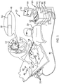
- FIG. 1 an illustration of an example medical system 20 is shown that may be used to generate and display information 52 (e.g., a chart, anatomical models of a portion of a patient and signal information).
- the system 20 and the tool 22 shown in FIG. 1 are merely by example.
- Medical tools, such as tool 22, can be any tool used for diagnostic or therapeutic treatment, such as for mapping electrical potentials in a heart 26 of a patient 28.
- tools may be used, mutatis mutandis, for other therapeutic and/or diagnostic purposes of different portions of anatomy, such as in the heart, lungs or other body organs, such as the ear, nose, and throat (ENT).
- Tools may include, for example, probes, catheters, cutting tools and suction devices.
- An operator 30 may insert the tool 22, which may include a non-tip section 54 and a tip 56 into a portion of patient anatomy, such as the vascular system of the patient 28 so that the tip 56 of the tool 22 enters a chamber of the heart 26.
- the control console 24 may use magnetic position sensing to determine position coordinates of the tool 22 (e.g., coordinates of the tip 56) in 3-D space inside the heart 26.
- a driver circuit 34 in the control console 24 may drive, via connector 44, field generators 36 to generate magnetic fields within the anatomy of the patient 28.
- the field generators 36 include one or more emitter coils (not shown in FIG. 1 ), placed at known positions external to the patient 28, which are configured to generate magnetic fields in a predefined working volume that contains a portion of interest of the patient anatomy. Each of the emitting coils is driven by a different frequency to emit a constant magnetic field in 3-D space. For example, in the example medical system 20 shown in FIG. 1 , one or more emitter coils can be placed below the torso of the patient 28 and each configured to generate magnetic fields in a predefined working volume that contains the heart 26 of the patient.
- a magnetic field location sensor 38 is disposed at the tip 56 of tool 22.
- the magnetic field location sensor 38 is used to determine the position of the receiving coil in 3-D space and generate electrical signals based on the amplitude and phase of the magnetic fields.
- a tool can include one or more magnetic field location sensors each disposed at any portion of the tool.
- the signals are wirelessly communicated to the control console 24 via a wireless communication interface at the tool 22 that may communicate with a corresponding input/output (I/O) interface 42 in the control console 24.
- the wireless communication interface and the I/O interface 42 may operate in accordance with any suitable wireless communication standard that is known in the art, such as for example, infrared (IR), radio frequency (RF), Bluetooth, one of the IEEE 802.11 family of standards (e.g., Wi-Fi), or the HiperLAN standard.
- the body surface electrodes 46 may include one or more wireless sensor nodes integrated on a flexible substrate.
- the one or more wireless sensor nodes may include a wireless transmit/receive unit (WTRU) enabling local digital signal processing, a radio link, and a miniaturized rechargeable battery, as described in more detail below.
- WTRU wireless transmit/receive unit
- the I/O interface 42 may enable the control console 24 to interact with the tool 22, the body surface electrodes 46 and the position sensors (not shown). Based on the electrical impulses received from the body surface electrodes 46 and the electrical signals received from the tool 22 via the I/O interface 42 and other components of medical system 20, the processor 40 may determine the location of the tool in 3-D space and generate the display information 52, which may be shown on a display 50. Although display information 52 is shown on a display 50, it is possible to generate and present the location of the tool 22 in any known manner such as audibly.
- Processor 40 which may include one or more processors, is configured to process the signals (e.g. process information contained in signal packets) to determine the position coordinates of the tip 56 in 3-D space, including both location and orientation coordinates.
- the location data can include points in 3-D space, strength of the magnetic field and a time stamp.
- the processor 40 may be also used to implement any portion of the methods for locating a tool in a 3D space described herein, such as determining the availability of location data and accelerometer data, determining the location of the tool 22 based on the location data, estimating the location of the tool 22 based on accelerometer data and previously calculated data (e.g., velocity and acceleration data), filtering (e.g., via a Kalman filter) estimated location data and generating the display information 52, which may be shown on a display 50.
- determining the availability of location data and accelerometer data determining the location of the tool 22 based on the location data, estimating the location of the tool 22 based on accelerometer data and previously calculated data (e.g., velocity and acceleration data), filtering (e.g., via a Kalman filter) estimated location data and generating the display information 52, which may be shown on a display 50.
- the magnetic field location sensor 38 transmits a signal to the control console 24 which indicates the location data of the tool 22 (e.g., location coordinates of the tip 56) in 3-D space.
- the magnetic field location sensor 38 may include one or more miniature receiving coils and may include multiple miniature coils oriented along different axes.
- the magnetic field location sensor 38 may include another type of magnetic sensor or position transducers of other types, such as impedance-based or ultrasonic location sensors.
- FIG. 1 shows the tool 22 having a single location sensor, embodiments may include tools with more than one location sensor. Magnetic position tracking techniques are described, for example, in U.S. Pat. Nos. 5,391,199 , 5,443,489 , 6,788,967 , 6,690,963 , 5,558,091 , 6,172,499 6,177,792 , whose disclosures are incorporated herein by reference.
- the tool 22 may also include an electrode 48 coupled to the tip 56 and configured to function as an impedance-based position transducer. Additionally or alternatively, the electrode 48 may be configured to measure a certain physiological property, for example the local surface electrical potential (e.g., of cardiac tissue) at one or more locations. The electrode 48 may be configured to apply RF energy to ablate endocardial tissue in the heart 26.
- an electrode 48 coupled to the tip 56 and configured to function as an impedance-based position transducer. Additionally or alternatively, the electrode 48 may be configured to measure a certain physiological property, for example the local surface electrical potential (e.g., of cardiac tissue) at one or more locations. The electrode 48 may be configured to apply RF energy to ablate endocardial tissue in the heart 26.
- a certain physiological property for example the local surface electrical potential (e.g., of cardiac tissue) at one or more locations.
- the electrode 48 may be configured to apply RF energy to ablate endocardial tissue in the heart 26.
- the processor 40 may be included in a general-purpose computer, with a suitable front end and interface circuits for receiving signals from the tool 22 and controlling the other components of the control console 24.
- the processor 40 may be programmed, using software, to perform the functions that are described herein.
- the software may be downloaded to the control console 24 in electronic form, over a network, for example, or it may be provided on non-transitory tangible media, such as optical, magnetic or electronic memory media.
- some or all of the functions of the processor 40 may be performed by dedicated or programmable digital hardware components.
- the control console 24 is connected, via cable 44, to body surface electrodes 46, each of which are attached to patient 28 using patches (e.g., indicated in FIG. 1 as circles around the electrodes 46) that adhere to the skin of the patient.
- body surface electrodes 46 may also be positioned on the patient using articles worn by patient 28 which include the body surface electrodes 46 and may also include one or more position sensors (not shown) indicating the location of the worn article.
- body surface electrodes 46 can be embedded in a vest that is configured to be worn by the patient 28.
- the body surface electrodes 46 assist in providing a location of the tool (e.g., catheter) in 3-D space by detecting electrical impulses generated by the polarization and depolarization of cardiac tissue and transmitting information to the control console 24, via the cable 44.
- the body surface electrodes 46 can be equipped with magnetic location tracking and can help identify and track the respiration cycle of the patient 28.
- the tool 22, the body surface electrodes 46 and other sensors may communicate with the control console 24 and one another via a wireless interface.
- a wireless catheter which is not physically connected to signal processing and/or computing apparatus and is incorporated herein by reference. Rather, a transmitter/receiver is attached to the proximal end of the catheter. The transmitter/receiver communicates with a signal processing and/or computer apparatus using wireless communication methods, such as IR, RF, Bluetooth, or acoustic transmissions.
- the processor 40 may present the display information 52 and may store data representing the information 52 in a memory 58.
- the memory 58 may include any suitable volatile and/or non-volatile memory, such as random access memory or a hard disk drive.
- the operator 30 may be able to manipulate the display information 52 using one or more input devices 59.
- the medical system 20 may include a second operator that manipulates the control console 24 while the operator 30 manipulates the tool 22. It should be noted that the configuration shown in FIG. 1 is exemplary. Any suitable configuration of the medical system 20 may be used and implemented.
- FIG. 2 is a block diagram illustrating example components of an example medical system 200 in which features described herein can be implemented.
- the system 200 includes tool 202, processing device 204 and display device 206.
- the display device 206 e.g., display 50 in FIG. 1
- the display device 206 may be in wired communication, wireless communication or a combination of wired and wireless communication, via one or more networks (e.g., the Internet, a local area network (LAN), or a wide area network (WAN)) with processing device 204.
- Display device 206 may include one or more displays each configured to display different information, such as the location of the tool over time and maps of patient anatomy (e.g., map of a patient heart).
- processing device 204 includes processor 214, memory 212 (e.g., for storing information and instructions to be executed by processor 214) and storage 220 (e.g., a hard disk or a removable media drive).
- the processing device 204 and display device 206 may, for example, be part of the exemplary control console 24 shown in FIG. 1 .
- tool 202 includes sensors 216.
- Sensors 216 may include one or more sensors (e.g., magnetic field location sensor 38 shown in FIG. 1 or sensors 316 shown in FIG. 3 ) for providing location signals to indicate the location of the tool 202 in 3-D space.
- the system 200 may also include additional sensors 210.
- the additional sensors 210 which may include one or more sensors separate from the tool 202, such as surface electrodes 46 as shown in FIG. 1 , for providing location signals indicating the location of the tool 202 in 3-D space.
- processing device 204 includes processor 214, which may include one or more processors.
- Processor 214 may process electromagnetic signals, record electromagnetic signals over time, filter electromagnetic signals, and generate and combine electromagnetic signal information, provide information for display and control display device 206 for displaying information on display device 206.
- Processor 214 may generate and interpolate mapping information for displaying maps of the heart on display device 206.
- Processor 214 may process the location information acquired from one or more sensors (e.g., one or more additional sensors 210 and one or more tool sensors 216) to determine location and orientation coordinates of the tool 202 (e.g., a tip portion of the tool).
- Processor 214 which is in communication with memory 212, may be used to implement any portion of the methods for locating a tool in a 3D space described herein. For example, processor 214 may calculate the velocity and acceleration data based on signals acquired via sensors 216 and estimate location data based on the velocity and acceleration data. In addition, processor 214 may determine whether location data, obtained at the tool 202, which corresponds to a location of the tool 202, is available for processing. If the location data is available, processor 214 provides the location data for displaying the location of the tool 202.
- processor 214 estimated location data, corresponding to an estimated location of the tool 202, based on the calculated velocity and an acceleration of the tool 202, and provides (e.g., to a display processor or to the display device 206) the estimated location data for displaying the location of the tool 202 according to the estimated location.
- Processor 214 may also drive display device 206 to display the location of the tool 202.
- tool 202 may include an accelerometer 208, which is shown in phantom in FIG. 2 , for detecting the acceleration of the tool 202 over time.
- tool 202 may also include a processor 218, which is also shown in phantom in FIG. 2 .
- Processor 218 may be used to perform one or more functions that are performed by processor 214. For example, processor 218 may be used to calculate the velocity and acceleration data of the tool 202 based on signals acquired via sensors 216. The calculated velocity and acceleration data may then be transmitted to the processing device 204. The processing device 204 may then determine the estimated location based on the velocity and acceleration data calculated by processor 218 at the tool 202. Processor 218 may also be used to generate estimated location data, corresponding to an estimated location of the tool 202 based on the calculated velocity and acceleration data, and transmit the estimated location data to the processing device 204. The velocity and acceleration data and the estimated location data can be transmitted from the tool 202 to processor 214 using any of a number of short range wireless transmission protocols.
- the accelerometer 208, processor 218, sensors 216 and additional sensors 210 shown in FIG. 2 may be in wired or wireless communication with processing device 204.
- Display device 206 may also be in wired or wireless communication with processing device 204.
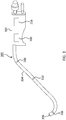
- FIG. 3 is an illustration of an example wireless tool 300 for use with embodiments described herein.
- tool 300 includes accelerometer 208 and processor 218.
- Wireless tool 300 includes a handle portion 302 and a probe portion 304.
- Probe portion 304 includes a tip 306 and sensors 316 disposed at different locations on the probe portion 304.
- the accelerometer 208 and processor 218 is disposed at the handle portion 302 of the wireless tool 300.
- the size and shape of tool 300 shown in FIG. 3 is merely exemplary.
- the location of each component (e.g., sensors 216, accelerometer 208 and processor 218) shown in FIG. 3 is also exemplary.
- the handle portion 302 is configured to be held by medical personnel for maneuvering the tool in 3-D space.
- the probe portion 304 is configured to be inserted into a patient during a medical procedure. As shown in FIG. 3 , the handle portion 302 is attached to the probe portion 304.
- the sensors 316 are, for example, used to determine the location of the tool 300 and may include an inductor (not shown) and resistors (not shown) for transmitting signals (e.g. voltage) to a processor (e.g., processor 214 in FIG. 2 ) remote from the tool 300.
- the number of sensors 316 shown in FIG. 3 is by way of example. Embodiments include tools having any number of sensors, including one sensor, disposed at any number of tool locations.
- the accelerometer 208, processor 218 and sensors 316 may be in wired or wireless communication with a processing device remote from the tool 300, such as processing device 204 shown in FIG. 2 .
- FIG. 4 is a flow diagram illustrating an example method 400 of locating the tool in 3-D space.
- the method 400 includes obtaining location data which corresponds to a location of a tool (e.g., tool 202) in 3D space over time.
- the location data may be obtained at the tool using one or more sensors (e.g. magnetic field location sensor 38 shown in FIG. 1 , or sensors 216 shown in FIG. 2 ) disposed at the tool.
- the location data includes, for example, locations (e.g., points, coordinates) in the 3-D space, the strength of the magnetic data, times at which data is acquired (e.g., time stamps), and any other information indicating a location of the tool in the 3D space over time.
- the method 400 includes calculating the velocity and the acceleration of the tool, at block 404, and estimating the location of the tool, at block 406.
- the velocity and acceleration may be calculated at the tool or remote from the tool.
- the location of the tool may be estimated at the tool or remote from the tool.
- the location data, obtained at the tool may be transmitted from the tool and the velocity and the acceleration of the tool may be calculated remote from the tool (e.g., via processor 214) using the received location data.
- the location of the tool may then be estimated remote from the tool (e.g., via processor 214) from the calculated velocity and the acceleration.
- the velocity and the acceleration of the tool may be calculated at the tool (e.g., via processor 218) using the obtained location data.
- the calculated velocity and acceleration may then be transmitted from the tool and the location of the tool may be estimated remote from the tool (e.g., via processor 214) from the calculated velocity and the acceleration calculated at the tool.
- the velocity and the acceleration of the tool may be calculated at the tool and the location of the tool may be estimated at the tool. The estimated location of the tool may then be provided remote from the tool to be displayed.
- the velocity of the tool is calculated using a change in location and a change in time.
- x is a previously acquired position of a tool acquired from block 402.
- V 2 x 2 ⁇ x 1 / dt
- x 1 , “x 2 ,” and “x 3 " are previously acquired positions of the tool at different times based on the location data obtained at block 402
- dt is the change in time between when two positions of the tool were acquired.
- the acceleration may then be calculated (e.g., via processor 218 or 214) using two previously calculated velocities (e.g., V 1 and V 2 ) of the tool.
- V 1 and V 2 previously calculated velocities
- the calculated velocity and acceleration of the tool may then be used to estimate a location of the tool, at block 406.
- the location data, obtained via the magnetic fields, is continually obtained over time such that location data, corresponding to a plurality of locations of the tool at different times, is obtained.
- the velocity and acceleration of the tool are also continually calculated for locations over time.
- estimated location data is determined based on the continually calculated velocity and acceleration.
- blocks 402-406 may be repeated, at equal intervals (e.g., 5 millisecond intervals), to continually estimate the location of the tool at the different locations over time.
- Each of blocks 402-406 may be repeated together (i.e., at the same equal intervals) or separate and independent from each other (i.e., at different intervals). Blocks 402-406 may also be repeated at unequal intervals, or performed upon the occurrence of an event or upon request.
- location data e.g., most recently obtained location data corresponding to the location of the tool
- Location data may be determined not to be available for a variety of reasons. For example, location data may not be available if location signals (e.g., signals from magnetic field location sensor 38) are not received, if location signals are not strong enough to obtain information or the location data is determined to be inaccurate.
- location signals e.g., signals from magnetic field location sensor 38
- the location data is determined not to be available at block 408, an estimation of the tool's location is performed. As shown in block 412, a determination is made as to whether accelerometer data is available for processing (e.g., by processor 214 or 218).
- the accelerometer data may not be available for a variety of reasons. For example, the accelerometer data may not be available if the tool is not equipped with an accelerometer, if the signals are not received, strong enough to acquire information end accelerometer data, or the accelerometer data is determined to be inaccurate.
- the data calculated at block 404 e.g., one or more calculated accelerations
- the estimated location data determined at block 406 is obtained (e.g., from the tool or from memory 212 or storage 220).
- the location of the tool estimated from the relative velocity and acceleration i.e., time when one or more velocities and accelerations are calculated relative to the current estimation
- estimated location data of the tool is generated if it is determined that the location data is not available.
- the calculated velocity and acceleration is obtained at 414 and then the estimated location data is generated using the relative velocity and acceleration.
- the accelerometer data is obtained at block 416 and the relative acceleration data of the accelerometer data obtained from the accelerometer is used to estimate the location of the tool at block 418.
- One or more previous velocity calculations performed in block 404 and one or more previous acceleration calculations, or accelerometer data may be used to estimate the location of the tool. For example, more recently (e.g., most recent) obtained velocity data, acceleration data and accelerometer data is used to estimate the location of the tool. In addition to or alternative to the more recently obtained data, other data prior to the more recently obtained data may be used, for example, because the more recent data may be inaccurate, include errors in calculation or may not be processable (e.g., signal including the data is not strong enough or signals are not received).
- a filter may be applied to the relative velocity and acceleration, obtained at block 418, to estimate the location of the tool.
- a Kalman filter is used.
- the estimated location data corresponding to an estimated location of the tool, is provided (e.g., to a display, a display processor, speaker) for presentation and the location of the tool is presented (e.g., visually displayed, aurally presented, or any other known method of presenting information) at the location indicated by the location data.
- the method proceeds back to block 402.
- processors include, by way of example, a general purpose processor, a special purpose processor, a conventional processor, a digital signal processor (DSP), a plurality of microprocessors, one or more microprocessors in association with a DSP core, a controller, a microcontroller, Application Specific Integrated Circuits (ASICs), Field Programmable Gate Arrays (FPGAs) circuits, any other type of integrated circuit (IC), and/or a state machine.
- DSP digital signal processor
- ASICs Application Specific Integrated Circuits
- FPGAs Field Programmable Gate Arrays
- Such processors can be manufactured by configuring a manufacturing process using the results of processed hardware description language (HDL) instructions and other intermediary data including netlists (such instructions capable of being stored on a computer readable media).
- HDL hardware description language
- netlists such instructions capable of being stored on a computer readable media.
- the results of such processing can be maskworks that are then used in a semiconductor manufacturing process to manufacture a processor which implements features of the disclosure.
- Non-transitory computer-readable storage mediums include a read only memory (ROM), a random access memory (RAM), a register, cache memory, semiconductor memory devices, magnetic media such as internal hard disks and removable disks, magneto-optical media, and optical media such as CD-ROM disks, and digital versatile disks (DVDs).
- ROM read only memory
- RAM random access memory
- register cache memory
- semiconductor memory devices magnetic media such as internal hard disks and removable disks, magneto-optical media, and optical media such as CD-ROM disks, and digital versatile disks (DVDs).
Abstract
Description
- A method for locating a tool in a three dimensional (3D) space is provided. The method includes determining whether location data, corresponding to a location of the tool, is available. If the location data is available, the method includes providing the location data for presenting the location of the tool. If the location data is not available, the method includes determining an estimated location of the tool based on a velocity of the tool and an acceleration of the tool, generating estimated location data corresponding to the estimated location of the tool and providing the estimated location data for presenting the estimated location as the location of the tool. The method also includes determining whether accelerometer data is available. If accelerometer data is available, the method includes using the accelerometer data to estimate the location of the tool.
- An electromagnetic navigation system for locating a tool in a 3D space is provided. The system includes memory configured to store data and a processor, in communication with the memory. The processor is configured to determine whether location data, corresponding to a location of the tool, is available. If the location data is available, the processor is configured to provide the location data for presenting the location of the tool. If the location data is not available, the processor is configured to determine an estimated location of the tool based on a velocity of the tool and an acceleration of the tool, generate estimated location data corresponding to the estimated location of the tool and provide the estimated location data for presenting the estimated location as the location of the tool.
- A non-transitory computer readable medium is provided. The computer readable medium has instructions which when executed cause a computer to perform a method of locating a tool in a 3D space. The method includes determining whether location data, corresponding to a location of the tool, is available. If the location data is available, the method includes providing the location data for presenting the location of the tool. If the location data is not available, the method includes determining an estimated location of the tool based on a velocity of the tool and an acceleration of the tool, generating estimated location data corresponding to the estimated location of the tool and providing the estimated location data for presenting the estimated location as the location of the tool. The method also includes determining whether accelerometer data is available. If accelerometer data is available, the method includes using the accelerometer data to estimate the location of the tool.
- A more detailed understanding can be had from the following description, given by way of example in conjunction with the accompanying drawings wherein:
-
FIG. 1 is an illustration of an example medical system for navigating a tool in a 3-D space within which embodiments disclosed herein may be implemented; -
FIG. 2 is a block diagram illustrating components of an example medical system for use with embodiments described herein; -
FIG. 3 is an illustration of an example wireless tool for use with embodiments described herein; and -
FIG. 4 is a flow diagram illustrating an example method of locating the tool in 3-D space according to an embodiment. - Electromagnetic navigation systems are used to determine the location of medical tools in a 3-D space during a medical procedure. During the procedures, medical tools generate and transmit signals (e.g., electrical signals based on the amplitude and phase of magnetic fields) to facilitate the determination of their locations. In some conventional systems, the signals are transmitted to system components via a wired medium (e.g., cable).
- Due to the advancement in short-range radio technology, however, some systems utilize tools that are wirelessly connected to the system components and the signals are wirelessly transmitted to the system components via various short range wireless protocols (Institute of Electrical Engineers (IEEE) 802.11g IrDA (infrared data) and Ericsson Bluetooth™). For example, medical personnel (e.g., ear, nose and throat (ENT) physicians and cardiologists) use battery-powered tools, such as catheters, for performing the medical procedures on patient anatomy. Based on the determined locations of the tools, anatomical information of a patient is presented (e.g., displayed) to the medical personnel. Accordingly, the efficiency and success of the procedures rely on continually providing the locations of the tools.
- The present application discloses systems, apparatuses and methods of using magnetic fields to calculate the location of medical tools in a 3-D space. Each tool is configured to wirelessly send data (e.g., location data using the magnetic fields (hereinafter "location data"), velocity data and acceleration data) to a processing device for mapping the location of the tool in the 3-D space. When the location data, corresponding to the location of the tool in the 3-D space at a point in time or time period, is not available (e.g., the location data is not received at the processing device, the data is inaccurate) for processing, the processing device uses previously calculated data to estimate the tool's location in a 3-D space. For example, the processing device uses previously calculated data corresponding to the tool's velocity and acceleration at different locations over time. The velocity and acceleration of the tool may be continually calculated during operation such that calculated data is available for processing to estimate the location of the tool when the location data is not available for processing. The processing device may also determine whether accelerometer data (i.e., acceleration data from an accelerometer at the tool) is available for processing and use the accelerometer data, in addition to or alternative to the previously calculated data, to estimate the tool's location in the 3-D space.
- Referring now to
FIG. 1 , an illustration of an examplemedical system 20 is shown that may be used to generate and display information 52 (e.g., a chart, anatomical models of a portion of a patient and signal information). Thesystem 20 and thetool 22 shown inFIG. 1 are merely by example. Medical tools, such astool 22, can be any tool used for diagnostic or therapeutic treatment, such as for mapping electrical potentials in aheart 26 of apatient 28. Alternatively, tools may be used, mutatis mutandis, for other therapeutic and/or diagnostic purposes of different portions of anatomy, such as in the heart, lungs or other body organs, such as the ear, nose, and throat (ENT). Tools may include, for example, probes, catheters, cutting tools and suction devices. - An
operator 30 may insert thetool 22, which may include anon-tip section 54 and atip 56 into a portion of patient anatomy, such as the vascular system of thepatient 28 so that thetip 56 of thetool 22 enters a chamber of theheart 26. Thecontrol console 24 may use magnetic position sensing to determine position coordinates of the tool 22 (e.g., coordinates of the tip 56) in 3-D space inside theheart 26. To determine the position coordinates, adriver circuit 34 in thecontrol console 24 may drive, viaconnector 44,field generators 36 to generate magnetic fields within the anatomy of thepatient 28. - The
field generators 36 include one or more emitter coils (not shown inFIG. 1 ), placed at known positions external to thepatient 28, which are configured to generate magnetic fields in a predefined working volume that contains a portion of interest of the patient anatomy. Each of the emitting coils is driven by a different frequency to emit a constant magnetic field in 3-D space. For example, in the examplemedical system 20 shown inFIG. 1 , one or more emitter coils can be placed below the torso of thepatient 28 and each configured to generate magnetic fields in a predefined working volume that contains theheart 26 of the patient. - As shown in
FIG. 1 , a magneticfield location sensor 38 is disposed at thetip 56 oftool 22. The magneticfield location sensor 38 is used to determine the position of the receiving coil in 3-D space and generate electrical signals based on the amplitude and phase of the magnetic fields. Although the magneticfield location sensor 38 is disposed at thetip 56 oftool 22, a tool can include one or more magnetic field location sensors each disposed at any portion of the tool. - The signals are wirelessly communicated to the
control console 24 via a wireless communication interface at thetool 22 that may communicate with a corresponding input/output (I/O)interface 42 in thecontrol console 24. The wireless communication interface and the I/O interface 42 may operate in accordance with any suitable wireless communication standard that is known in the art, such as for example, infrared (IR), radio frequency (RF), Bluetooth, one of the IEEE 802.11 family of standards (e.g., Wi-Fi), or the HiperLAN standard. Thebody surface electrodes 46 may include one or more wireless sensor nodes integrated on a flexible substrate. The one or more wireless sensor nodes may include a wireless transmit/receive unit (WTRU) enabling local digital signal processing, a radio link, and a miniaturized rechargeable battery, as described in more detail below. - The I/
O interface 42 may enable thecontrol console 24 to interact with thetool 22, thebody surface electrodes 46 and the position sensors (not shown). Based on the electrical impulses received from thebody surface electrodes 46 and the electrical signals received from thetool 22 via the I/O interface 42 and other components ofmedical system 20, theprocessor 40 may determine the location of the tool in 3-D space and generate thedisplay information 52, which may be shown on adisplay 50. Althoughdisplay information 52 is shown on adisplay 50, it is possible to generate and present the location of thetool 22 in any known manner such as audibly. -
Processor 40, which may include one or more processors, is configured to process the signals (e.g. process information contained in signal packets) to determine the position coordinates of thetip 56 in 3-D space, including both location and orientation coordinates. The location data can include points in 3-D space, strength of the magnetic field and a time stamp. Theprocessor 40 may be also used to implement any portion of the methods for locating a tool in a 3D space described herein, such as determining the availability of location data and accelerometer data, determining the location of thetool 22 based on the location data, estimating the location of thetool 22 based on accelerometer data and previously calculated data (e.g., velocity and acceleration data), filtering (e.g., via a Kalman filter) estimated location data and generating thedisplay information 52, which may be shown on adisplay 50. - The method of position sensing described hereinabove is implemented in the CART mapping system produced by Biosense Webster Inc., of Diamond Bar, Calif., and is described in detail in the patents and the patent applications cited herein.
- The magnetic
field location sensor 38 transmits a signal to thecontrol console 24 which indicates the location data of the tool 22 (e.g., location coordinates of the tip 56) in 3-D space. The magneticfield location sensor 38 may include one or more miniature receiving coils and may include multiple miniature coils oriented along different axes. Alternatively, the magneticfield location sensor 38 may include another type of magnetic sensor or position transducers of other types, such as impedance-based or ultrasonic location sensors. AlthoughFIG. 1 shows thetool 22 having a single location sensor, embodiments may include tools with more than one location sensor. Magnetic position tracking techniques are described, for example, inU.S. Pat. Nos. 5,391,199 ,5,443,489 ,6,788,967 ,6,690,963 ,5,558,091 ,6,172,499 6,177,792 , whose disclosures are incorporated herein by reference. - The
tool 22 may also include anelectrode 48 coupled to thetip 56 and configured to function as an impedance-based position transducer. Additionally or alternatively, theelectrode 48 may be configured to measure a certain physiological property, for example the local surface electrical potential (e.g., of cardiac tissue) at one or more locations. Theelectrode 48 may be configured to apply RF energy to ablate endocardial tissue in theheart 26. - The
processor 40 may be included in a general-purpose computer, with a suitable front end and interface circuits for receiving signals from thetool 22 and controlling the other components of thecontrol console 24. Theprocessor 40 may be programmed, using software, to perform the functions that are described herein. The software may be downloaded to thecontrol console 24 in electronic form, over a network, for example, or it may be provided on non-transitory tangible media, such as optical, magnetic or electronic memory media. Alternatively, some or all of the functions of theprocessor 40 may be performed by dedicated or programmable digital hardware components. - In the example shown at
FIG. 1 , thecontrol console 24 is connected, viacable 44, tobody surface electrodes 46, each of which are attached topatient 28 using patches (e.g., indicated inFIG. 1 as circles around the electrodes 46) that adhere to the skin of the patient. In addition or alternative to the patches,body surface electrodes 46 may also be positioned on the patient using articles worn bypatient 28 which include thebody surface electrodes 46 and may also include one or more position sensors (not shown) indicating the location of the worn article. For example,body surface electrodes 46 can be embedded in a vest that is configured to be worn by thepatient 28. During operation, thebody surface electrodes 46 assist in providing a location of the tool (e.g., catheter) in 3-D space by detecting electrical impulses generated by the polarization and depolarization of cardiac tissue and transmitting information to thecontrol console 24, via thecable 44. Thebody surface electrodes 46 can be equipped with magnetic location tracking and can help identify and track the respiration cycle of thepatient 28. - Additionally or alternatively, the
tool 22, thebody surface electrodes 46 and other sensors (not shown) may communicate with thecontrol console 24 and one another via a wireless interface. For example,U.S. Pat. No. 6,266,551 , whose disclosure is incorporated herein by reference, describes, inter alia, a wireless catheter, which is not physically connected to signal processing and/or computing apparatus and is incorporated herein by reference. Rather, a transmitter/receiver is attached to the proximal end of the catheter. The transmitter/receiver communicates with a signal processing and/or computer apparatus using wireless communication methods, such as IR, RF, Bluetooth, or acoustic transmissions. - During the diagnostic treatment, the
processor 40 may present thedisplay information 52 and may store data representing theinformation 52 in amemory 58. Thememory 58 may include any suitable volatile and/or non-volatile memory, such as random access memory or a hard disk drive. Theoperator 30 may be able to manipulate thedisplay information 52 using one ormore input devices 59. Alternatively, themedical system 20 may include a second operator that manipulates thecontrol console 24 while theoperator 30 manipulates thetool 22. It should be noted that the configuration shown inFIG. 1 is exemplary. Any suitable configuration of themedical system 20 may be used and implemented. -
FIG. 2 is a block diagram illustrating example components of an examplemedical system 200 in which features described herein can be implemented. As shown inFIG. 2 , thesystem 200 includestool 202,processing device 204 anddisplay device 206. The display device 206 (e.g.,display 50 inFIG. 1 ) may be in wired communication, wireless communication or a combination of wired and wireless communication, via one or more networks (e.g., the Internet, a local area network (LAN), or a wide area network (WAN)) withprocessing device 204.Display device 206 may include one or more displays each configured to display different information, such as the location of the tool over time and maps of patient anatomy (e.g., map of a patient heart). - As shown in
FIG. 2 ,processing device 204 includesprocessor 214, memory 212 (e.g., for storing information and instructions to be executed by processor 214) and storage 220 (e.g., a hard disk or a removable media drive). Theprocessing device 204 anddisplay device 206 may, for example, be part of theexemplary control console 24 shown inFIG. 1 . - As shown in
FIG. 2 ,tool 202 includessensors 216.Sensors 216 may include one or more sensors (e.g., magneticfield location sensor 38 shown inFIG. 1 orsensors 316 shown inFIG. 3 ) for providing location signals to indicate the location of thetool 202 in 3-D space. As shown inFIG. 2 , thesystem 200 may also includeadditional sensors 210. Theadditional sensors 210, which may include one or more sensors separate from thetool 202, such assurface electrodes 46 as shown inFIG. 1 , for providing location signals indicating the location of thetool 202 in 3-D space. - As shown in
FIG. 2 ,processing device 204 includesprocessor 214, which may include one or more processors.Processor 214 may process electromagnetic signals, record electromagnetic signals over time, filter electromagnetic signals, and generate and combine electromagnetic signal information, provide information for display andcontrol display device 206 for displaying information ondisplay device 206.Processor 214 may generate and interpolate mapping information for displaying maps of the heart ondisplay device 206.Processor 214 may process the location information acquired from one or more sensors (e.g., one or moreadditional sensors 210 and one or more tool sensors 216) to determine location and orientation coordinates of the tool 202 (e.g., a tip portion of the tool). -
Processor 214, which is in communication withmemory 212, may be used to implement any portion of the methods for locating a tool in a 3D space described herein. For example,processor 214 may calculate the velocity and acceleration data based on signals acquired viasensors 216 and estimate location data based on the velocity and acceleration data. In addition,processor 214 may determine whether location data, obtained at thetool 202, which corresponds to a location of thetool 202, is available for processing. If the location data is available,processor 214 provides the location data for displaying the location of thetool 202. If the location data is not available,processor 214 estimated location data, corresponding to an estimated location of thetool 202, based on the calculated velocity and an acceleration of thetool 202, and provides (e.g., to a display processor or to the display device 206) the estimated location data for displaying the location of thetool 202 according to the estimated location.Processor 214 may also drivedisplay device 206 to display the location of thetool 202. - In some embodiments,
tool 202 may include anaccelerometer 208, which is shown in phantom inFIG. 2 , for detecting the acceleration of thetool 202 over time. In some embodiments,tool 202 may also include aprocessor 218, which is also shown in phantom inFIG. 2 . -
Processor 218 may be used to perform one or more functions that are performed byprocessor 214. For example,processor 218 may be used to calculate the velocity and acceleration data of thetool 202 based on signals acquired viasensors 216. The calculated velocity and acceleration data may then be transmitted to theprocessing device 204. Theprocessing device 204 may then determine the estimated location based on the velocity and acceleration data calculated byprocessor 218 at thetool 202.Processor 218 may also be used to generate estimated location data, corresponding to an estimated location of thetool 202 based on the calculated velocity and acceleration data, and transmit the estimated location data to theprocessing device 204. The velocity and acceleration data and the estimated location data can be transmitted from thetool 202 toprocessor 214 using any of a number of short range wireless transmission protocols. - The
accelerometer 208,processor 218,sensors 216 andadditional sensors 210 shown inFIG. 2 may be in wired or wireless communication withprocessing device 204.Display device 206 may also be in wired or wireless communication withprocessing device 204. -
FIG. 3 is an illustration of anexample wireless tool 300 for use with embodiments described herein. As shown inFIG. 3 ,tool 300 includesaccelerometer 208 andprocessor 218.Wireless tool 300 includes ahandle portion 302 and aprobe portion 304.Probe portion 304 includes atip 306 andsensors 316 disposed at different locations on theprobe portion 304. As shown inFIG. 3 , theaccelerometer 208 andprocessor 218 is disposed at thehandle portion 302 of thewireless tool 300. The size and shape oftool 300 shown inFIG. 3 is merely exemplary. In addition, the location of each component (e.g.,sensors 216,accelerometer 208 and processor 218) shown inFIG. 3 is also exemplary. - The
handle portion 302 is configured to be held by medical personnel for maneuvering the tool in 3-D space. Theprobe portion 304 is configured to be inserted into a patient during a medical procedure. As shown inFIG. 3 , thehandle portion 302 is attached to theprobe portion 304. Thesensors 316 are, for example, used to determine the location of thetool 300 and may include an inductor (not shown) and resistors (not shown) for transmitting signals (e.g. voltage) to a processor (e.g.,processor 214 inFIG. 2 ) remote from thetool 300. The number ofsensors 316 shown inFIG. 3 is by way of example. Embodiments include tools having any number of sensors, including one sensor, disposed at any number of tool locations. - The
accelerometer 208,processor 218 andsensors 316 may be in wired or wireless communication with a processing device remote from thetool 300, such asprocessing device 204 shown inFIG. 2 . -
FIG. 4 is a flow diagram illustrating anexample method 400 of locating the tool in 3-D space. As shown inblock 402, themethod 400 includes obtaining location data which corresponds to a location of a tool (e.g., tool 202) in 3D space over time. The location data may be obtained at the tool using one or more sensors (e.g. magneticfield location sensor 38 shown inFIG. 1 , orsensors 216 shown inFIG. 2 ) disposed at the tool. The location data includes, for example, locations (e.g., points, coordinates) in the 3-D space, the strength of the magnetic data, times at which data is acquired (e.g., time stamps), and any other information indicating a location of the tool in the 3D space over time. - As shown in
FIG. 4 , themethod 400 includes calculating the velocity and the acceleration of the tool, atblock 404, and estimating the location of the tool, atblock 406. The velocity and acceleration may be calculated at the tool or remote from the tool. In addition, the location of the tool may be estimated at the tool or remote from the tool. - For example, in one embodiment, the location data, obtained at the tool, may be transmitted from the tool and the velocity and the acceleration of the tool may be calculated remote from the tool (e.g., via processor 214) using the received location data. The location of the tool may then be estimated remote from the tool (e.g., via processor 214) from the calculated velocity and the acceleration. In another embodiment, the velocity and the acceleration of the tool may be calculated at the tool (e.g., via processor 218) using the obtained location data. The calculated velocity and acceleration may then be transmitted from the tool and the location of the tool may be estimated remote from the tool (e.g., via processor 214) from the calculated velocity and the acceleration calculated at the tool. In yet another embodiment, the velocity and the acceleration of the tool may be calculated at the tool and the location of the tool may be estimated at the tool. The estimated location of the tool may then be provided remote from the tool to be displayed.
- In an example embodiment, the velocity of the tool is calculated using a change in location and a change in time. For example, assume that "x" is a previously acquired position of a tool acquired from
block 402. A first velocity V1 may be calculated using the Equation 1:
- A second velocity, V2 may be calculated using Equation 2:

block 402, and dt is the change in time between when two positions of the tool were acquired. - The acceleration may then be calculated (e.g., via
processor 218 or 214) using two previously calculated velocities (e.g., V1 and V2) of the tool. For example, an acceleration "a" of the tool may be calculated using Equation 3:
- The calculated velocity and acceleration of the tool may then be used to estimate a location of the tool, at
block 406. For example, the estimated location of the tool may be calculated using the sum of a previous location, a calculated velocity and a calculated acceleration, such as Equation 4:
- The equations described above, used to calculate the velocity and acceleration and estimate the location, are merely used as an example.
- The location data, obtained via the magnetic fields, is continually obtained over time such that location data, corresponding to a plurality of locations of the tool at different times, is obtained. The velocity and acceleration of the tool are also continually calculated for locations over time. As shown at
block 406, estimated location data is determined based on the continually calculated velocity and acceleration. For example, blocks 402-406 may be repeated, at equal intervals (e.g., 5 millisecond intervals), to continually estimate the location of the tool at the different locations over time. Each of blocks 402-406 may be repeated together (i.e., at the same equal intervals) or separate and independent from each other (i.e., at different intervals). Blocks 402-406 may also be repeated at unequal intervals, or performed upon the occurrence of an event or upon request. - As shown at
block 408 ofFIG. 4 , a determination is made as to whether location data (e.g., most recently obtained location data corresponding to the location of the tool), obtained fromblock 402, is available for processing (e.g., processing byprocessor 214 or 218). That is, a determination is made as to whether location data, obtained via the magnetic fields, is available. If the location data is determined to be available, the location data is provided (e.g., to a display, a display processor, speaker), for presentation atblock 410 and the location of the tool is presented (e.g., visually displayed, aurally presented, or any other known method of presenting information) at the location indicated by the location data. After the location of the tool is provided atblock 410, the method proceeds back to block 402. - Location data may be determined not to be available for a variety of reasons. For example, location data may not be available if location signals (e.g., signals from magnetic field location sensor 38) are not received, if location signals are not strong enough to obtain information or the location data is determined to be inaccurate.
- If the location data is determined not to be available at
block 408, an estimation of the tool's location is performed. As shown inblock 412, a determination is made as to whether accelerometer data is available for processing (e.g., byprocessor 214 or 218). The accelerometer data may not be available for a variety of reasons. For example, the accelerometer data may not be available if the tool is not equipped with an accelerometer, if the signals are not received, strong enough to acquire information end accelerometer data, or the accelerometer data is determined to be inaccurate. - As shown at
block 414, if it is determined that the accelerometer data is not available, the data calculated at block 404 (e.g., one or more calculated accelerations) and the estimated location data determined atblock 406, is obtained (e.g., from the tool or frommemory 212 or storage 220). The location of the tool estimated from the relative velocity and acceleration (i.e., time when one or more velocities and accelerations are calculated relative to the current estimation), is used atblock 418 to estimate the location (e.g., the current location) of the tool. That is, in the example shown atFIG. 4 , estimated location data of the tool is continually generated over time (e.g., at equal intervals) atblock 406, based on the calculated velocity and acceleration of the tool atblock 404, prior to determining whether the location data is available atblock 408. - In another example, estimated location data of the tool is generated if it is determined that the location data is not available. In this example, the calculated velocity and acceleration is obtained at 414 and then the estimated location data is generated using the relative velocity and acceleration.
- If the accelerometer data is determined to be available, the accelerometer data is obtained at
block 416 and the relative acceleration data of the accelerometer data obtained from the accelerometer is used to estimate the location of the tool atblock 418. - One or more previous velocity calculations performed in
block 404 and one or more previous acceleration calculations, or accelerometer data, may be used to estimate the location of the tool. For example, more recently (e.g., most recent) obtained velocity data, acceleration data and accelerometer data is used to estimate the location of the tool. In addition to or alternative to the more recently obtained data, other data prior to the more recently obtained data may be used, for example, because the more recent data may be inaccurate, include errors in calculation or may not be processable (e.g., signal including the data is not strong enough or signals are not received). - As shown in
block 420, a filter may be applied to the relative velocity and acceleration, obtained atblock 418, to estimate the location of the tool. In one exemplary embodiment, a Kalman filter is used. For example, Equation 5 may be used to estimate the location of the tool:
- As shown at
block 422, the estimated location data, corresponding to an estimated location of the tool, is provided (e.g., to a display, a display processor, speaker) for presentation and the location of the tool is presented (e.g., visually displayed, aurally presented, or any other known method of presenting information) at the location indicated by the location data. After the estimated location of the tool is provided atblock 422, the method proceeds back to block 402. - Any of the functions and methods described herein can be implemented in a general purpose computer, a processor, or a processor core. Suitable processors include, by way of example, a general purpose processor, a special purpose processor, a conventional processor, a digital signal processor (DSP), a plurality of microprocessors, one or more microprocessors in association with a DSP core, a controller, a microcontroller, Application Specific Integrated Circuits (ASICs), Field Programmable Gate Arrays (FPGAs) circuits, any other type of integrated circuit (IC), and/or a state machine. Such processors can be manufactured by configuring a manufacturing process using the results of processed hardware description language (HDL) instructions and other intermediary data including netlists (such instructions capable of being stored on a computer readable media). The results of such processing can be maskworks that are then used in a semiconductor manufacturing process to manufacture a processor which implements features of the disclosure.
- Any of the functions and methods described herein can be implemented in a computer program, software, or firmware incorporated in a non-transitory computer-readable storage medium for execution by a general purpose computer or a processor. Examples of non-transitory computer-readable storage mediums include a read only memory (ROM), a random access memory (RAM), a register, cache memory, semiconductor memory devices, magnetic media such as internal hard disks and removable disks, magneto-optical media, and optical media such as CD-ROM disks, and digital versatile disks (DVDs).
- It should be understood that many variations are possible based on the disclosure herein. Although features and elements are described above in particular combinations, each feature or element can be used alone without the other features and elements or in various combinations with or without other features and elements.
Claims (20)
- A method for locating a tool in a three dimensional (3D) space, comprising:determining whether location data, corresponding to a location of the tool, is available;if the location data is available, providing the location data for presenting the location of the tool;if the location data is not available:determining an estimated location of the tool based on a velocity of the tool and an acceleration of the tool;generating estimated location data corresponding to the estimated location of the tool; andproviding the estimated location data for presenting the estimated location as the location of the tool.
- The method of claim 1, further comprising:receiving an indication of the location of the tool; andgenerating the indication of the location of the tool.
- The method of claim 1, wherein if the location data is not available,
determining whether accelerometer data, which indicates the acceleration of the tool, is available; and
if the accelerometer data is available, determining the estimated location of the tool based on the accelerometer data. - The method of claim 1, further comprising:calculating the velocity of the tool and acceleration of the tool for a plurality of locations over time, anddetermining whether accelerometer data, which indicates the acceleration of the tool, is available; andif the accelerometer data is not available, determining the estimated location of the tool using one or more previous velocity calculations and one or more previous acceleration calculations of the tool.
- The method of claim 4, wherein:the one or more previous velocity calculations comprise calculating the velocity of the tool based on a change in location and a change in time; andthe one or more previous acceleration calculations comprise calculating the acceleration based on a change in the velocity and a change in time.
- The method of claim 1, wherein the estimated location of the tool is determined remote from the tool.
- The method of claim 1, wherein the estimated location of the tool is determined remote at the tool.
- The method of claim 1, wherein if the location data is not available:filtering, via a Kalman filter, the estimated location data to provide filtered estimated location data; andproviding the filtered estimated location data for presenting the estimated location of the tool.
- An electromagnetic navigation system for locating a tool in a three dimensional (3D) space, the system comprising:memory configured to store data; anda processor, in communication with the memory, configured to:determine whether location data, corresponding to a location of the tool, is available;if the location data is available, provide the location data for presenting the location of the tool;if the location data is not available:determine an estimated location of the tool based on a velocity of the tool and an acceleration of the tool;generate estimated location data corresponding to the estimated location of the tool; andprovide the estimated location data for presenting the estimated location as the location of the tool.
- The electromagnetic navigation system of claim 9, wherein the processor is further configured to:receive electrical signals indicating a plurality of locations of the tool over time; andgenerate the location data based on the electrical signals.
- The electromagnetic navigation system of claim 9, wherein if the location data is not available, the processor is further configured to determine whether accelerometer data, which indicates the acceleration of the tool, is available; and
if the accelerometer data is available, the processor is further configured to determine the estimated location of the tool based on the velocity of the tool and the accelerometer data. - The electromagnetic navigation system of claim 9, wherein the velocity and acceleration of the tool are calculated, over time, for each of a plurality of locations, and
the processor is further configured to determine whether accelerometer data, which indicates the acceleration of the tool, is available; and
if the accelerometer data is not available, the processor is further configured to determine the estimated location of the tool by using one or more previous velocity calculations and one or more previous acceleration calculations of the tool. - The electromagnetic navigation system of claim 12, wherein:the one or more previous velocity calculations comprise calculating the velocity of the tool based on a change in location and a change in time; andthe one or more previous acceleration calculations comprise calculating the acceleration based on a change in the velocity and a change in time.
- The electromagnetic navigation system of claim 9, wherein if the location data is not available:filtering, via a Kalman filter, the estimated location data to provide filtered estimated location data; andproviding the filtered estimated location data for presenting the estimated location of the tool.
- A non-transitory computer readable medium having instructions which, when executed, cause a computer to perform a method of locating a tool in a three dimensional (3D) space, comprising:determining whether location data, corresponding to a location of the tool, is available;if the location data is available, providing the location data for presenting the location of the tool;if the location data is not available:determining estimated location data, corresponding to an estimated location of the tool based on a velocity of the tool and an acceleration of the tool; andproviding the estimated location data for presenting the estimated location of the tool.
- The non-transitory computer readable medium according to claim 15, wherein the method further comprises:receiving electrical signals indicating the location of the tool; andgenerating the location data based on the electrical signals.
- The non-transitory computer readable medium according to claim 15, wherein if the location data is not available, the method further comprises:determining whether accelerometer data, which indicates the acceleration of the tool, is available; andif the accelerometer data is available, determining the estimated location of the tool based on the velocity of the tool and the accelerometer data.
- The non-transitory computer readable medium according to claim 15, wherein the method further comprises:calculating the velocity and acceleration of the tool for a plurality of locations over time; anddetermining whether accelerometer data, which indicates the acceleration of the tool, is available; andif the accelerometer data is not available, determining the estimated location of the tool further comprises determining a current estimated location of the tool using one or more previous velocity and acceleration calculations of the tool at one or more previous locations.
- The non-transitory computer readable medium according to claim 18, wherein the method further comprises:calculating the velocity of the tool based on a change in location and a change in time; andcalculating the acceleration based on a change in the velocity and a change in time.
- The non-transitory computer readable medium of claim 15, wherein the method further comprises:
if the location data is not available:filtering, via a Kalman filter, the estimated location data to provide filtered estimated location data; andproviding the filtered estimated location data for presenting the estimated location of the tool.
Applications Claiming Priority (2)
| Application Number | Priority Date | Filing Date | Title |
|---|---|---|---|
| US201762489019P | 2017-04-24 | 2017-04-24 | |
| US15/935,777 US11646113B2 (en) | 2017-04-24 | 2018-03-26 | Systems and methods for determining magnetic location of wireless tools |
Publications (2)
| Publication Number | Publication Date |
|---|---|
| EP3395246A1 true EP3395246A1 (en) | 2018-10-31 |
| EP3395246B1 EP3395246B1 (en) | 2020-11-04 |
Family
ID=62062905
Family Applications (1)
| Application Number | Title | Priority Date | Filing Date |
|---|---|---|---|
| EP18168987.8A Active EP3395246B1 (en) | 2017-04-24 | 2018-04-24 | Systems and methods for determining magnetic location of wireless tools |
Country Status (7)
| Country | Link |
|---|---|
| US (1) | US11646113B2 (en) |
| EP (1) | EP3395246B1 (en) |
| JP (1) | JP7134689B2 (en) |
| CN (1) | CN108836335B (en) |
| AU (1) | AU2018202621A1 (en) |
| CA (1) | CA3002313A1 (en) |
| IL (1) | IL258605B (en) |
Families Citing this family (2)
| Publication number | Priority date | Publication date | Assignee | Title |
|---|---|---|---|---|
| CN109620303B (en) * | 2018-11-26 | 2022-09-02 | 苏州朗开医疗技术有限公司 | Lung auxiliary diagnosis method and device |
| CN116098707B (en) * | 2023-04-13 | 2023-07-11 | 青岛大学附属医院 | Wireless electromagnetic wave guided teleoperation system |
Citations (11)
| Publication number | Priority date | Publication date | Assignee | Title |
|---|---|---|---|---|
| US5391199A (en) | 1993-07-20 | 1995-02-21 | Biosense, Inc. | Apparatus and method for treating cardiac arrhythmias |
| US5558091A (en) | 1993-10-06 | 1996-09-24 | Biosense, Inc. | Magnetic determination of position and orientation |
| US6172499B1 (en) | 1999-10-29 | 2001-01-09 | Ascension Technology Corporation | Eddy current error-reduced AC magnetic position measurement system |
| US6177792B1 (en) | 1996-03-26 | 2001-01-23 | Bisense, Inc. | Mutual induction correction for radiator coils of an objects tracking system |
| EP1096268A2 (en) * | 1999-10-28 | 2001-05-02 | Northern Digital Inc. | System for determining the spatial position and/or orientation of one or more objects |
| US6266551B1 (en) | 1996-02-15 | 2001-07-24 | Biosense, Inc. | Catheter calibration and usage monitoring system |
| US6611141B1 (en) * | 1998-12-23 | 2003-08-26 | Howmedica Leibinger Inc | Hybrid 3-D probe tracked by multiple sensors |
| US6690963B2 (en) | 1995-01-24 | 2004-02-10 | Biosense, Inc. | System for determining the location and orientation of an invasive medical instrument |
| US20090149740A1 (en) * | 2007-12-11 | 2009-06-11 | Siemens Aktiengesellschaft | A medical intervention device |
| EP2632381A1 (en) * | 2010-10-29 | 2013-09-04 | Medtronic, Inc. | Error correction techniques in surgical navigation |
| US20140128739A1 (en) * | 2012-11-07 | 2014-05-08 | General Electric Company | Ultrasound imaging system and method |
Family Cites Families (42)
| Publication number | Priority date | Publication date | Assignee | Title |
|---|---|---|---|---|
| US7343195B2 (en) * | 1999-05-18 | 2008-03-11 | Mediguide Ltd. | Method and apparatus for real time quantitative three-dimensional image reconstruction of a moving organ and intra-body navigation |
| US6735465B2 (en) * | 2001-10-24 | 2004-05-11 | Scimed Life Systems, Inc. | Systems and processes for refining a registered map of a body cavity |
| US20040039420A1 (en) * | 2002-08-26 | 2004-02-26 | Medtronic Physio-Control Manufacturing Corp. | Apparatus, software, and methods for cardiac pulse detection using accelerometer data |
| DE602004030110D1 (en) | 2003-05-21 | 2010-12-30 | Philips Intellectual Property | DEVICE FOR NAVIGATING A CATHETER |
| US8235055B2 (en) * | 2005-01-11 | 2012-08-07 | Uti Limited Partnership | Magnetic levitation of intraluminal microelectronic capsule |
| US20060287824A1 (en) * | 2005-01-29 | 2006-12-21 | American Gnc Corporation | Interruption free navigator |
| US20060241397A1 (en) * | 2005-02-22 | 2006-10-26 | Assaf Govari | Reference pad for position sensing |
| US9492226B2 (en) * | 2005-12-06 | 2016-11-15 | St. Jude Medical, Atrial Fibrillation Division, Inc. | Graphical user interface for real-time RF lesion depth display |
| US20070270686A1 (en) * | 2006-05-03 | 2007-11-22 | Ritter Rogers C | Apparatus and methods for using inertial sensing to navigate a medical device |
| US20160317843A9 (en) * | 2006-05-12 | 2016-11-03 | Vytronus, Inc. | Integrated ablation and mapping system |
| US20140051968A1 (en) * | 2007-01-16 | 2014-02-20 | Radiadyne, Llc | Rectal balloon with sensor cable |
| US8543189B2 (en) * | 2007-04-23 | 2013-09-24 | Medtronic Navigation, Inc. | Method and apparatus for electromagnetic navigation of a magnetic stimulation probe |
| US8797214B2 (en) * | 2007-07-06 | 2014-08-05 | Qualcomm Incorporated | Tracking implementing geopositioning and local modes |
| US20090082660A1 (en) * | 2007-09-20 | 2009-03-26 | Norbert Rahn | Clinical workflow for treatment of atrial fibrulation by ablation using 3d visualization of pulmonary vein antrum in 2d fluoroscopic images |
| US10299753B2 (en) * | 2007-11-29 | 2019-05-28 | Biosense Webster, Inc. | Flashlight view of an anatomical structure |
| CN102470014B (en) * | 2009-06-29 | 2016-07-20 | 皇家飞利浦电子股份有限公司 | For the method and apparatus being tracked in medical procedure |
| US20120095330A1 (en) * | 2009-06-29 | 2012-04-19 | Koninklijke Philips Electronics N.V. | Method and system for position determination |
| US20110071759A1 (en) * | 2009-09-22 | 2011-03-24 | Texas Instruments Incorporated | Performance of a Navigation Receiver Operating in a Power-Save Mode with the Aid of Sensors |
| US8454589B2 (en) * | 2009-11-20 | 2013-06-04 | St. Jude Medical, Atrial Fibrillation Division, Inc. | System and method for assessing effective delivery of ablation therapy |
| US20120232377A1 (en) * | 2011-03-10 | 2012-09-13 | Nottmeier Eric W | Surgical navigation for revision surgical procedure |
| US9151823B2 (en) * | 2012-02-24 | 2015-10-06 | Broadcom Corporation | Wireless communication device capable of accurately performing position estimations |
| US10282064B2 (en) * | 2012-06-20 | 2019-05-07 | Koninklijke Philips N.V. | Graphical user interface for medical instruments |
| US9052391B2 (en) * | 2012-08-01 | 2015-06-09 | Caterpillar Inc. | Backup velocity estimation utilizing traction device speed |
| US8923959B2 (en) * | 2012-08-27 | 2014-12-30 | Birinder Robert Boveja | Methods and system for real-time cardiac mapping |
| WO2014036439A2 (en) * | 2012-08-31 | 2014-03-06 | Acutus Medical, Inc. | Catheter system and methods of medical uses of same, including diagnostic and treatment uses for the heart |
| US8457880B1 (en) * | 2012-11-28 | 2013-06-04 | Cambridge Mobile Telematics | Telematics using personal mobile devices |
| US9820677B2 (en) | 2013-01-03 | 2017-11-21 | St. Jude Medical, Atrial Fibrillation Division, Inc. | Cointegration filter for a catheter navigation system |
| JP6273355B2 (en) * | 2013-10-30 | 2018-01-31 | セント・ジュード・メディカル,カーディオロジー・ディヴィジョン,インコーポレイテッド | Cardiac mapping system and method for voltage-based assessment of electrograms |
| US20150305823A1 (en) | 2014-04-25 | 2015-10-29 | General Electric Company | System and method for processing navigational sensor data |
| WO2015166487A1 (en) * | 2014-04-28 | 2015-11-05 | Mazor Robotics Ltd. | Ultrasound guided hand held robot |
| EP3182874B1 (en) * | 2014-08-22 | 2023-06-14 | Parmar, Jaywant P. | Advanced electromagnetic motion and tracking peripherally inserted central venous catheter system with extended endovascular applications |
| CN107072573B (en) * | 2014-10-15 | 2018-11-16 | 圣犹达医疗用品心脏病学部门有限公司 | For generating the method and system for being directed to the integrated substrate-based mapping figure of arrhythmia cordis |
| US20160146616A1 (en) * | 2014-11-21 | 2016-05-26 | Alpine Electronics, Inc. | Vehicle positioning by map matching as feedback for ins/gps navigation system during gps signal loss |
| WO2016154274A2 (en) * | 2015-03-24 | 2016-09-29 | Zoll Medical Corporation | Systems and methods of determining location using a medical device |
| US9436993B1 (en) * | 2015-04-17 | 2016-09-06 | Clear Guide Medical, Inc | System and method for fused image based navigation with late marker placement |
| US10238350B2 (en) * | 2015-05-08 | 2019-03-26 | St. Jude Medical, Cardiology Division, Inc. | System and method for real-time electrophysiological mapping |
| US20160354158A1 (en) * | 2015-06-05 | 2016-12-08 | Pacesetter, Inc. | Methods and systems for virtual venous imaging |
| WO2017019754A1 (en) * | 2015-07-27 | 2017-02-02 | Paul Kessman | Systems, apparatus, and methods for electro-anatomical mapping of a catheter with electode contact assessment and rotor projection |
| US20170065353A1 (en) * | 2015-09-04 | 2017-03-09 | Biosense Webster (Israel) Ltd. | Identifying and presenting suspected map shifts |
| CN108601925B (en) * | 2015-12-04 | 2021-06-29 | 项目莫里股份有限公司 | Input and articulation system for catheters and other uses |
| US9791279B1 (en) * | 2016-06-30 | 2017-10-17 | U-Blox Ag | System for and method of determining angular position of a vehicle |
| FR3059541B1 (en) * | 2016-12-07 | 2021-05-07 | Bay Labs Inc | GUIDED NAVIGATION OF AN ULTRASONIC PROBE |
-
2018
- 2018-03-26 US US15/935,777 patent/US11646113B2/en active Active
- 2018-04-10 IL IL258605A patent/IL258605B/en active IP Right Grant
- 2018-04-16 AU AU2018202621A patent/AU2018202621A1/en not_active Abandoned
- 2018-04-20 CA CA3002313A patent/CA3002313A1/en not_active Abandoned
- 2018-04-23 JP JP2018082063A patent/JP7134689B2/en active Active
- 2018-04-24 EP EP18168987.8A patent/EP3395246B1/en active Active
- 2018-04-24 CN CN201810376949.XA patent/CN108836335B/en active Active
Patent Citations (13)
| Publication number | Priority date | Publication date | Assignee | Title |
|---|---|---|---|---|
| US5443489A (en) | 1993-07-20 | 1995-08-22 | Biosense, Inc. | Apparatus and method for ablation |
| US5391199A (en) | 1993-07-20 | 1995-02-21 | Biosense, Inc. | Apparatus and method for treating cardiac arrhythmias |
| US5558091A (en) | 1993-10-06 | 1996-09-24 | Biosense, Inc. | Magnetic determination of position and orientation |
| US6690963B2 (en) | 1995-01-24 | 2004-02-10 | Biosense, Inc. | System for determining the location and orientation of an invasive medical instrument |
| US6266551B1 (en) | 1996-02-15 | 2001-07-24 | Biosense, Inc. | Catheter calibration and usage monitoring system |
| US6177792B1 (en) | 1996-03-26 | 2001-01-23 | Bisense, Inc. | Mutual induction correction for radiator coils of an objects tracking system |
| US6788967B2 (en) | 1997-05-14 | 2004-09-07 | Biosense, Inc. | Medical diagnosis, treatment and imaging systems |
| US6611141B1 (en) * | 1998-12-23 | 2003-08-26 | Howmedica Leibinger Inc | Hybrid 3-D probe tracked by multiple sensors |
| EP1096268A2 (en) * | 1999-10-28 | 2001-05-02 | Northern Digital Inc. | System for determining the spatial position and/or orientation of one or more objects |
| US6172499B1 (en) | 1999-10-29 | 2001-01-09 | Ascension Technology Corporation | Eddy current error-reduced AC magnetic position measurement system |
| US20090149740A1 (en) * | 2007-12-11 | 2009-06-11 | Siemens Aktiengesellschaft | A medical intervention device |
| EP2632381A1 (en) * | 2010-10-29 | 2013-09-04 | Medtronic, Inc. | Error correction techniques in surgical navigation |
| US20140128739A1 (en) * | 2012-11-07 | 2014-05-08 | General Electric Company | Ultrasound imaging system and method |
Also Published As
| Publication number | Publication date |
|---|---|
| US20180308577A1 (en) | 2018-10-25 |
| US11646113B2 (en) | 2023-05-09 |
| CN108836335B (en) | 2022-09-27 |
| AU2018202621A1 (en) | 2018-11-08 |
| CN108836335A (en) | 2018-11-20 |
| CA3002313A1 (en) | 2018-10-24 |
| IL258605B (en) | 2021-04-29 |
| EP3395246B1 (en) | 2020-11-04 |
| JP7134689B2 (en) | 2022-09-12 |
| JP2018183584A (en) | 2018-11-22 |
| IL258605A (en) | 2018-06-28 |
Similar Documents
| Publication | Publication Date | Title |
|---|---|---|
| CN109589091B (en) | Interactive display for selected ECG channels | |
| EP3461446B1 (en) | Ablation size estimation and visual representation | |
| EP3395246B1 (en) | Systems and methods for determining magnetic location of wireless tools | |
| US11701050B2 (en) | Data reuse for filling in missing data points | |
| EP3396810B1 (en) | Using location transmission signals for charging a wireless tool of an electromagnetic navigation system | |
| EP3444822B1 (en) | System and method of managing ecg data for user defined map |
Legal Events
| Date | Code | Title | Description |
|---|---|---|---|
| PUAI | Public reference made under article 153(3) epc to a published international application that has entered the european phase |
Free format text: ORIGINAL CODE: 0009012 |
|
| STAA | Information on the status of an ep patent application or granted ep patent |
Free format text: STATUS: THE APPLICATION HAS BEEN PUBLISHED |
|
| AK | Designated contracting states |
Kind code of ref document: A1 Designated state(s): AL AT BE BG CH CY CZ DE DK EE ES FI FR GB GR HR HU IE IS IT LI LT LU LV MC MK MT NL NO PL PT RO RS SE SI SK SM TR |
|
| AX | Request for extension of the european patent |
Extension state: BA ME |
|
| STAA | Information on the status of an ep patent application or granted ep patent |
Free format text: STATUS: REQUEST FOR EXAMINATION WAS MADE |
|
| 17P | Request for examination filed |
Effective date: 20181212 |
|
| RBV | Designated contracting states (corrected) |
Designated state(s): AL AT BE BG CH CY CZ DE DK EE ES FI FR GB GR HR HU IE IS IT LI LT LU LV MC MK MT NL NO PL PT RO RS SE SI SK SM TR |
|
| GRAP | Despatch of communication of intention to grant a patent |
Free format text: ORIGINAL CODE: EPIDOSNIGR1 |
|
| STAA | Information on the status of an ep patent application or granted ep patent |
Free format text: STATUS: GRANT OF PATENT IS INTENDED |
|
| INTG | Intention to grant announced |
Effective date: 20200520 |
|
| GRAS | Grant fee paid |
Free format text: ORIGINAL CODE: EPIDOSNIGR3 |
|
| GRAA | (expected) grant |
Free format text: ORIGINAL CODE: 0009210 |
|
| STAA | Information on the status of an ep patent application or granted ep patent |
Free format text: STATUS: THE PATENT HAS BEEN GRANTED |
|
| AK | Designated contracting states |
Kind code of ref document: B1 Designated state(s): AL AT BE BG CH CY CZ DE DK EE ES FI FR GB GR HR HU IE IS IT LI LT LU LV MC MK MT NL NO PL PT RO RS SE SI SK SM TR |
|
| REG | Reference to a national code |
Ref country code: GB Ref legal event code: FG4D |
|
| REG | Reference to a national code |
Ref country code: CH Ref legal event code: EP |
|
| REG | Reference to a national code |
Ref country code: AT Ref legal event code: REF Ref document number: 1329762 Country of ref document: AT Kind code of ref document: T Effective date: 20201115 |
|
| REG | Reference to a national code |
Ref country code: IE Ref legal event code: FG4D |
|
| REG | Reference to a national code |
Ref country code: DE Ref legal event code: R096 Ref document number: 602018009295 Country of ref document: DE |
|
| REG | Reference to a national code |
Ref country code: NL Ref legal event code: FP |
|
| REG | Reference to a national code |
Ref country code: AT Ref legal event code: MK05 Ref document number: 1329762 Country of ref document: AT Kind code of ref document: T Effective date: 20201104 |
|
| PG25 | Lapsed in a contracting state [announced via postgrant information from national office to epo] |
Ref country code: RS Free format text: LAPSE BECAUSE OF FAILURE TO SUBMIT A TRANSLATION OF THE DESCRIPTION OR TO PAY THE FEE WITHIN THE PRESCRIBED TIME-LIMIT Effective date: 20201104 Ref country code: PT Free format text: LAPSE BECAUSE OF FAILURE TO SUBMIT A TRANSLATION OF THE DESCRIPTION OR TO PAY THE FEE WITHIN THE PRESCRIBED TIME-LIMIT Effective date: 20210304 Ref country code: FI Free format text: LAPSE BECAUSE OF FAILURE TO SUBMIT A TRANSLATION OF THE DESCRIPTION OR TO PAY THE FEE WITHIN THE PRESCRIBED TIME-LIMIT Effective date: 20201104 Ref country code: GR Free format text: LAPSE BECAUSE OF FAILURE TO SUBMIT A TRANSLATION OF THE DESCRIPTION OR TO PAY THE FEE WITHIN THE PRESCRIBED TIME-LIMIT Effective date: 20210205 Ref country code: NO Free format text: LAPSE BECAUSE OF FAILURE TO SUBMIT A TRANSLATION OF THE DESCRIPTION OR TO PAY THE FEE WITHIN THE PRESCRIBED TIME-LIMIT Effective date: 20210204 |
|
| PG25 | Lapsed in a contracting state [announced via postgrant information from national office to epo] |
Ref country code: AT Free format text: LAPSE BECAUSE OF FAILURE TO SUBMIT A TRANSLATION OF THE DESCRIPTION OR TO PAY THE FEE WITHIN THE PRESCRIBED TIME-LIMIT Effective date: 20201104 Ref country code: ES Free format text: LAPSE BECAUSE OF FAILURE TO SUBMIT A TRANSLATION OF THE DESCRIPTION OR TO PAY THE FEE WITHIN THE PRESCRIBED TIME-LIMIT Effective date: 20201104 Ref country code: BG Free format text: LAPSE BECAUSE OF FAILURE TO SUBMIT A TRANSLATION OF THE DESCRIPTION OR TO PAY THE FEE WITHIN THE PRESCRIBED TIME-LIMIT Effective date: 20210204 Ref country code: SE Free format text: LAPSE BECAUSE OF FAILURE TO SUBMIT A TRANSLATION OF THE DESCRIPTION OR TO PAY THE FEE WITHIN THE PRESCRIBED TIME-LIMIT Effective date: 20201104 Ref country code: PL Free format text: LAPSE BECAUSE OF FAILURE TO SUBMIT A TRANSLATION OF THE DESCRIPTION OR TO PAY THE FEE WITHIN THE PRESCRIBED TIME-LIMIT Effective date: 20201104 Ref country code: LV Free format text: LAPSE BECAUSE OF FAILURE TO SUBMIT A TRANSLATION OF THE DESCRIPTION OR TO PAY THE FEE WITHIN THE PRESCRIBED TIME-LIMIT Effective date: 20201104 Ref country code: IS Free format text: LAPSE BECAUSE OF FAILURE TO SUBMIT A TRANSLATION OF THE DESCRIPTION OR TO PAY THE FEE WITHIN THE PRESCRIBED TIME-LIMIT Effective date: 20210304 |
|
| REG | Reference to a national code |
Ref country code: LT Ref legal event code: MG9D |
|
| PG25 | Lapsed in a contracting state [announced via postgrant information from national office to epo] |
Ref country code: HR Free format text: LAPSE BECAUSE OF FAILURE TO SUBMIT A TRANSLATION OF THE DESCRIPTION OR TO PAY THE FEE WITHIN THE PRESCRIBED TIME-LIMIT Effective date: 20201104 |
|
| PG25 | Lapsed in a contracting state [announced via postgrant information from national office to epo] |
Ref country code: EE Free format text: LAPSE BECAUSE OF FAILURE TO SUBMIT A TRANSLATION OF THE DESCRIPTION OR TO PAY THE FEE WITHIN THE PRESCRIBED TIME-LIMIT Effective date: 20201104 Ref country code: CZ Free format text: LAPSE BECAUSE OF FAILURE TO SUBMIT A TRANSLATION OF THE DESCRIPTION OR TO PAY THE FEE WITHIN THE PRESCRIBED TIME-LIMIT Effective date: 20201104 Ref country code: SM Free format text: LAPSE BECAUSE OF FAILURE TO SUBMIT A TRANSLATION OF THE DESCRIPTION OR TO PAY THE FEE WITHIN THE PRESCRIBED TIME-LIMIT Effective date: 20201104 Ref country code: LT Free format text: LAPSE BECAUSE OF FAILURE TO SUBMIT A TRANSLATION OF THE DESCRIPTION OR TO PAY THE FEE WITHIN THE PRESCRIBED TIME-LIMIT Effective date: 20201104 Ref country code: SK Free format text: LAPSE BECAUSE OF FAILURE TO SUBMIT A TRANSLATION OF THE DESCRIPTION OR TO PAY THE FEE WITHIN THE PRESCRIBED TIME-LIMIT Effective date: 20201104 Ref country code: RO Free format text: LAPSE BECAUSE OF FAILURE TO SUBMIT A TRANSLATION OF THE DESCRIPTION OR TO PAY THE FEE WITHIN THE PRESCRIBED TIME-LIMIT Effective date: 20201104 |
|
| REG | Reference to a national code |
Ref country code: DE Ref legal event code: R097 Ref document number: 602018009295 Country of ref document: DE |
|
| PG25 | Lapsed in a contracting state [announced via postgrant information from national office to epo] |
Ref country code: DK Free format text: LAPSE BECAUSE OF FAILURE TO SUBMIT A TRANSLATION OF THE DESCRIPTION OR TO PAY THE FEE WITHIN THE PRESCRIBED TIME-LIMIT Effective date: 20201104 |
|
| PLBE | No opposition filed within time limit |
Free format text: ORIGINAL CODE: 0009261 |
|
| STAA | Information on the status of an ep patent application or granted ep patent |
Free format text: STATUS: NO OPPOSITION FILED WITHIN TIME LIMIT |
|
| 26N | No opposition filed |
Effective date: 20210805 |
|
| PG25 | Lapsed in a contracting state [announced via postgrant information from national office to epo] |
Ref country code: AL Free format text: LAPSE BECAUSE OF FAILURE TO SUBMIT A TRANSLATION OF THE DESCRIPTION OR TO PAY THE FEE WITHIN THE PRESCRIBED TIME-LIMIT Effective date: 20201104 |
|
| PG25 | Lapsed in a contracting state [announced via postgrant information from national office to epo] |
Ref country code: SI Free format text: LAPSE BECAUSE OF FAILURE TO SUBMIT A TRANSLATION OF THE DESCRIPTION OR TO PAY THE FEE WITHIN THE PRESCRIBED TIME-LIMIT Effective date: 20201104 Ref country code: MC Free format text: LAPSE BECAUSE OF FAILURE TO SUBMIT A TRANSLATION OF THE DESCRIPTION OR TO PAY THE FEE WITHIN THE PRESCRIBED TIME-LIMIT Effective date: 20201104 |
|
| PG25 | Lapsed in a contracting state [announced via postgrant information from national office to epo] |
Ref country code: LU Free format text: LAPSE BECAUSE OF NON-PAYMENT OF DUE FEES Effective date: 20210424 |
|
| REG | Reference to a national code |
Ref country code: BE Ref legal event code: MM Effective date: 20210430 |
|
| PG25 | Lapsed in a contracting state [announced via postgrant information from national office to epo] |
Ref country code: LI Free format text: LAPSE BECAUSE OF NON-PAYMENT OF DUE FEES Effective date: 20210430 Ref country code: CH Free format text: LAPSE BECAUSE OF NON-PAYMENT OF DUE FEES Effective date: 20210430 |
|
| PG25 | Lapsed in a contracting state [announced via postgrant information from national office to epo] |
Ref country code: IE Free format text: LAPSE BECAUSE OF NON-PAYMENT OF DUE FEES Effective date: 20210424 |
|
| PG25 | Lapsed in a contracting state [announced via postgrant information from national office to epo] |
Ref country code: IS Free format text: LAPSE BECAUSE OF FAILURE TO SUBMIT A TRANSLATION OF THE DESCRIPTION OR TO PAY THE FEE WITHIN THE PRESCRIBED TIME-LIMIT Effective date: 20210304 |
|
| PGFP | Annual fee paid to national office [announced via postgrant information from national office to epo] |
Ref country code: NL Payment date: 20220314 Year of fee payment: 5 |
|
| PG25 | Lapsed in a contracting state [announced via postgrant information from national office to epo] |
Ref country code: BE Free format text: LAPSE BECAUSE OF NON-PAYMENT OF DUE FEES Effective date: 20210430 |
|
| PGFP | Annual fee paid to national office [announced via postgrant information from national office to epo] |
Ref country code: FR Payment date: 20230309 Year of fee payment: 6 |
|
| PGFP | Annual fee paid to national office [announced via postgrant information from national office to epo] |
Ref country code: IT Payment date: 20230310 Year of fee payment: 6 |
|
| PG25 | Lapsed in a contracting state [announced via postgrant information from national office to epo] |
Ref country code: CY Free format text: LAPSE BECAUSE OF FAILURE TO SUBMIT A TRANSLATION OF THE DESCRIPTION OR TO PAY THE FEE WITHIN THE PRESCRIBED TIME-LIMIT Effective date: 20201104 |
|
| PG25 | Lapsed in a contracting state [announced via postgrant information from national office to epo] |
Ref country code: HU Free format text: LAPSE BECAUSE OF FAILURE TO SUBMIT A TRANSLATION OF THE DESCRIPTION OR TO PAY THE FEE WITHIN THE PRESCRIBED TIME-LIMIT; INVALID AB INITIO Effective date: 20180424 |
|
| PGFP | Annual fee paid to national office [announced via postgrant information from national office to epo] |
Ref country code: DE Payment date: 20230228 Year of fee payment: 6 |
|
| REG | Reference to a national code |
Ref country code: NL Ref legal event code: MM Effective date: 20230501 |
|
| PG25 | Lapsed in a contracting state [announced via postgrant information from national office to epo] |
Ref country code: NL Free format text: LAPSE BECAUSE OF NON-PAYMENT OF DUE FEES Effective date: 20230501 |
|
| PG25 | Lapsed in a contracting state [announced via postgrant information from national office to epo] |
Ref country code: MK Free format text: LAPSE BECAUSE OF FAILURE TO SUBMIT A TRANSLATION OF THE DESCRIPTION OR TO PAY THE FEE WITHIN THE PRESCRIBED TIME-LIMIT Effective date: 20201104 |
|
| PGFP | Annual fee paid to national office [announced via postgrant information from national office to epo] |
Ref country code: GB Payment date: 20240229 Year of fee payment: 7 |