EP3389780B1 - Method for determining a patient specific locally varying margin - Google Patents
Method for determining a patient specific locally varying margin Download PDFInfo
- Publication number
- EP3389780B1 EP3389780B1 EP16822441.8A EP16822441A EP3389780B1 EP 3389780 B1 EP3389780 B1 EP 3389780B1 EP 16822441 A EP16822441 A EP 16822441A EP 3389780 B1 EP3389780 B1 EP 3389780B1
- Authority
- EP
- European Patent Office
- Prior art keywords
- medical image
- treatment target
- patient specific
- location
- determining
- Prior art date
- Legal status (The legal status is an assumption and is not a legal conclusion. Google has not performed a legal analysis and makes no representation as to the accuracy of the status listed.)
- Active
Links
- 238000000034 method Methods 0.000 title claims description 34
- 238000011282 treatment Methods 0.000 claims description 53
- 210000000920 organ at risk Anatomy 0.000 claims description 32
- 238000001959 radiotherapy Methods 0.000 claims description 32
- 238000006073 displacement reaction Methods 0.000 claims description 18
- 238000004590 computer program Methods 0.000 claims description 12
- 230000011218 segmentation Effects 0.000 claims description 10
- 238000002059 diagnostic imaging Methods 0.000 claims description 6
- 238000004364 calculation method Methods 0.000 claims description 3
- 230000036962 time dependent Effects 0.000 claims description 2
- 210000003918 fraction a Anatomy 0.000 claims 1
- 238000002595 magnetic resonance imaging Methods 0.000 description 11
- 206010028980 Neoplasm Diseases 0.000 description 5
- 210000002307 prostate Anatomy 0.000 description 5
- 230000005855 radiation Effects 0.000 description 4
- 201000011510 cancer Diseases 0.000 description 3
- 210000000664 rectum Anatomy 0.000 description 3
- 238000013213 extrapolation Methods 0.000 description 2
- 238000010191 image analysis Methods 0.000 description 2
- 210000000056 organ Anatomy 0.000 description 2
- 206010060862 Prostate cancer Diseases 0.000 description 1
- 208000000236 Prostatic Neoplasms Diseases 0.000 description 1
- 230000003542 behavioural effect Effects 0.000 description 1
- 210000000988 bone and bone Anatomy 0.000 description 1
- 230000001419 dependent effect Effects 0.000 description 1
- 230000035622 drinking Effects 0.000 description 1
- 230000005672 electromagnetic field Effects 0.000 description 1
- 230000005284 excitation Effects 0.000 description 1
- 238000011337 individualized treatment Methods 0.000 description 1
- 210000004072 lung Anatomy 0.000 description 1
- 239000003550 marker Substances 0.000 description 1
- 238000011002 quantification Methods 0.000 description 1
- 230000002040 relaxant effect Effects 0.000 description 1
- 230000029058 respiratory gaseous exchange Effects 0.000 description 1
- 230000009897 systematic effect Effects 0.000 description 1
- 239000013598 vector Substances 0.000 description 1
Images

Classifications
-
- A—HUMAN NECESSITIES
- A61—MEDICAL OR VETERINARY SCIENCE; HYGIENE
- A61N—ELECTROTHERAPY; MAGNETOTHERAPY; RADIATION THERAPY; ULTRASOUND THERAPY
- A61N5/00—Radiation therapy
- A61N5/10—X-ray therapy; Gamma-ray therapy; Particle-irradiation therapy
- A61N5/103—Treatment planning systems
- A61N5/1037—Treatment planning systems taking into account the movement of the target, e.g. 4D-image based planning
-
- A—HUMAN NECESSITIES
- A61—MEDICAL OR VETERINARY SCIENCE; HYGIENE
- A61N—ELECTROTHERAPY; MAGNETOTHERAPY; RADIATION THERAPY; ULTRASOUND THERAPY
- A61N5/00—Radiation therapy
- A61N5/10—X-ray therapy; Gamma-ray therapy; Particle-irradiation therapy
- A61N5/103—Treatment planning systems
- A61N5/1039—Treatment planning systems using functional images, e.g. PET or MRI
-
- A—HUMAN NECESSITIES
- A61—MEDICAL OR VETERINARY SCIENCE; HYGIENE
- A61N—ELECTROTHERAPY; MAGNETOTHERAPY; RADIATION THERAPY; ULTRASOUND THERAPY
- A61N5/00—Radiation therapy
- A61N5/10—X-ray therapy; Gamma-ray therapy; Particle-irradiation therapy
- A61N5/103—Treatment planning systems
- A61N5/1038—Treatment planning systems taking into account previously administered plans applied to the same patient, i.e. adaptive radiotherapy
Definitions
- the invention relates to the field of radiation therapy.
- Radiation therapy planning is a complex process, comprising four steps:
- the challenge in the whole process is to distribute a high dose to the cancer cells and a low dose to the healthy cells, especially to sensitive organs at risk.
- a number of unknown parameters have to be estimated, e.g., the tumor spread, the patient motion and positioning inaccuracy. This estimation must achieve a fine balance between sufficient dose to the treatment target while keeping organs at risk below a maximum tolerable dose.
- the patient motion is compensated for with a margin or treatment margin all around a specific structure (treatment target or organ at risk).
- a margin or treatment margin all around a specific structure (treatment target or organ at risk).
- radiotherapy planning e.g., by elongating a target volume in the lung with the help of a breathing phase reconstructed 4D CT.
- some motion uncertainty is being compensated by strict behavioral protocols, such as drinking and eating protocols for prostate patients to achieve a consistent bladder and rectum filling during irradiation.
- US 20140073833 A1 describes methods, systems and computer-readable storage media that relate to determining individualized treatment planning margins.
- the methods may include processing motion data of a target obtained from at least one marker for one or more periods. Each period may include a plurality of time intervals.
- the processing may include processing the motion data to determine an isocenter for each time interval along at least one of the axes of motion.
- the axes can include the x axis, the y axis, and/or the z axis.
- the method may include determining motion prediction data for each of the at least one of the axes; and determining treatment planning margins for each of the at least one of the axes based on the motion prediction data.
- Some patient motion during radiotherapy is highly inhomogeneous and varies greatly between individuals. Examples are the filling of the bladder or movement of the rectum during the time of prostate irradiation. Currently, this motion is compensated for with generic margins around the treatment target and / or organ at risk.
- motion quantification can be location specific: there could be regions of the treatment target and / or organ at risk, which will not move due to outer forces: e.g., because of bone restrictions.
- the first and second location could be anatomical landmarks, but they could also be implanted markers.
- more than 2 medical images are acquired over the acquisition time interval.
- the patient specific and locally varying margin is determined based on a measure of variation in the positions of the first and second locations.
- the first medical image is an MRI image suitable to be used for a generation of a pseudo CT image of the treatment target.
- This embodiment is advantageous, because in this way an image that needs to be acquired anyway in an MRI based radiotherapy workflow can in addition be used to determine the patient specific locally varying margin.
- the second medical image is an image suitable to be used for segmentation of the treatment target.
- This embodiment is advantageous, because in this way an image that needs to be acquired anyway in order to delineate the treatment target can be used in addition to determine the patient specific locally varying margin.
- This embodiment is even more advantageous when the second medical image is an MRI image and when the first medical image is an MRI image suitable to be used for a generation of a pseudo CT image of the treatment target.
- the images that need to be acquired anyway to support an MRI based radiotherapy planning can be used in addition to determine the patient specific locally varying margin. In this way, the information on which the patient specific locally varying margin is based can be almost or completely obtained for free in the sense that no extra time is needed for the image acquisition.
- the method further comprises a step of displaying the displacement of the first location and the displacement of the second location between the acquisition of the first medical image and the acquisition of the second medical image to a user.
- the method further comprises a step of calculating an interpolated position and / or extrapolated position of the first location and the second location and displaying the interpolated position and / or extrapolated position to the user.
- This embodiment is advantageous, because it provides the clinician more freedom on how to apply a margin.
- the positions determined by the first medical image could be assumed to be at 0%.
- the positions determined by the second medical image could be assumed to be at 100%. If a clinician wants to be on the safe side for a certain structure, he may want to apply a margin on the extrapolated positions or contour (e.g. 120%). In this way he is more certain that the objectives for this structure will be met in practice. On the other hand, conservative margins on one structure may make it more complicated to meet the objectives for the other structures. Therefore, the clinician may also want to choose an interpolated margin for some structures.
- the position of the first and second location are determined based on segmentation of the treatment target and/or organ at risk. This is advantageous because this method is relatively easy to automate and will thereby result in more reproducible results. Segmentation is not the only way how positions could be determined. Alternative solutions are known to the skilled person, e.g. he could decide to look for the displacement of individual landmarks in the first medical image and second medical image.
- this object is also achieved according to computer program product according to claim 12.
- This computer program product is configured for image analysis. This is advantageous, because in this way image analysis could also be performed at a stand-alone workstation.
- the computer program product further comprises program code means for causing a computer to carry out the steps of a method of acquiring the first medical image of the treatment target and /or organ at risk and acquiring the second medical image of the treatment target and / or organ at risk, wherein the time between the acquisition of the first medical image and the second medical image is similar to a radiotherapy fraction time interval.
- This embodiment is especially advantageous when the computer program product is installed on a medical imaging system. In this way, the medical image system can analyze the image directly after acquisition.
- the computer program product is configured to perform any of the method steps described above.
- this object is achieved by a medical imaging system according to claim 15.
- the medical imaging system could be configured such that it is suitable to perform any of the methods described above.
- FIG. 1 illustrates diagrammatically a medical imaging system, in this case a magnetic resonance imaging (MRI) system in which the invention is used.
- the MRI system comprises a main magnet 10 which generates a steady homogeneous main magnetic field within the examination zone 14. This main magnetic field causes a partial orientation of the spins in the object to be examined along the field lines of the main magnetic field.
- An RF system is provided with one or more RF antennae 12 to emit an RF excitation electromagnetic field into the examination zone 14 to excite spins in the body of the object to be examined.
- the relaxing spins emit magnetic resonance signals in the RF range which are picked up by the RF antennae 12, notably in the form of RF receiving coils.
- gradient coils 16 are provided to generate temporary magnetic gradient fields, notably read gradient pulses and phase encoding gradients. These gradient fields usually are orientated in mutual orthogonal directions and impose spatial encoding on the magnetic resonance signals.
- Gradient amplifiers (GradAmp(x,y,z)) 18 are provided to activate the gradient coils 16 to generate the magnetic gradient encoding fields.
- the magnetic resonance signals picked up by the RF receiver antennae 12 are applied to an MRI data acquisition (MRIacq) 19 system which comprises a spectrometer.
- the MRI data acquisition system provides the data to a host computer (HC) 20, which in turn provides it to a reconstructor (Recon) 22, which reconstructs an image from the data.
- the host computer could further comprise a computer program product, which will be configured to perform the methods steps as described below.
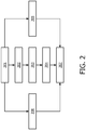
- Figure 2 illustrates diagrammatically a method according to the invention.
- Figure 2 is a flow chart. The method is further illustrated by means of the example shown in figure 3.
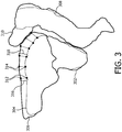
- Figure 3 illustrates diagrammatically segmentations of a treatment target and organs at risk based on a first medical image and a second medical image.
- the method according to embodiments of the invention is a method for determining a patient specific locally varying margin on a treatment target 302 ( figure 3 ) and / or an organ at risk 304, 308 ( figure 3 ) in order to compensate for local intrafraction motion expected during a radiotherapy fraction to be delivered over a radiotherapy fraction time interval.
- the radiotherapy time interval is dependent on the organ to be treated and on the complexity of the radiotherapy plan.
- the organ to be treated is known beforehand and the clinician can decide beforehand about the desired complexity of the plan (e.g. conformal, intensity modulated radiotherapy, VMAT). Therefore, the radiotherapy time interval is predictable before the actual creation of the radiotherapy plan. For a prostate cancer treatment the radiotherapy time interval is nowadays most often between 5-15 minutes.
- the patient specific locally varying margin is determined based on a displacement and / or an estimate of the displacement of at least a first location 312 ( figure 3 ) and a second location 314 ( figure 3 ) on the treatment target and / or organ at risk.
- the method to determine the patient specific locally varying margin comprises the following steps:
- the displacement of the first location, second location and optionally further locations can be displayed to a user in many different ways.
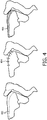
- Figure 4 shows a few examples of how the displacement of the first location, second location and optionally further locations can be displayed to a user.
- the displacement can be displayed by an overlay of two segmentations 402.
- displacement vectors could be displayed to the user 404.
- line thickness can be varied to indicate the extent of displacement 406.
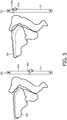
- Figure 5 illustrates diagrammatically an example of how an interpolation and extrapolation of the contour 502, 506 can be displayed to the user.
- a slider 501 is provided by which means the user can indicated what interpolated or extrapolated contour he wishes to see.
- a slider position at 50% 504 shows contour 502.
- a slider position at 120% 508 shows contour 506.
- the user can use this information to decide which of these margins he wants to use during treatment in order to compensate for intrafraction motion. Also he may decide to use multiple margins during a single fraction.
Landscapes
- Health & Medical Sciences (AREA)
- Engineering & Computer Science (AREA)
- Biomedical Technology (AREA)
- Pathology (AREA)
- Nuclear Medicine, Radiotherapy & Molecular Imaging (AREA)
- Radiology & Medical Imaging (AREA)
- Life Sciences & Earth Sciences (AREA)
- Animal Behavior & Ethology (AREA)
- General Health & Medical Sciences (AREA)
- Public Health (AREA)
- Veterinary Medicine (AREA)
- Radiation-Therapy Devices (AREA)
- Magnetic Resonance Imaging Apparatus (AREA)
Description
- The invention relates to the field of radiation therapy.
- Radiation therapy planning is a complex process, comprising four steps:
- 1. On a given patient image a treatment target and one or more organs at risk are delineated (manually or by (semi-)automatic methods).
- 2. Several margins for irradiation inaccuracy, patient motion, or sub-clinical cancer cells outside the visible tumor are added.
- 3. Then the treatment target and one or more organs at risk are equipped with a number of objectives for the radiation, e.g. maximal/minimal doses.
- 4. Then a computer program optimizes beam parameters to get as close as possible to those objectives.
- The challenge in the whole process is to distribute a high dose to the cancer cells and a low dose to the healthy cells, especially to sensitive organs at risk. For this, a number of unknown parameters have to be estimated, e.g., the tumor spread, the patient motion and positioning inaccuracy. This estimation must achieve a fine balance between sufficient dose to the treatment target while keeping organs at risk below a maximum tolerable dose.
- Often, the patient motion is compensated for with a margin or treatment margin all around a specific structure (treatment target or organ at risk). There are efforts to quantify systematic errors and include them in radiotherapy planning, e.g., by elongating a target volume in the lung with the help of a breathing phase reconstructed 4D CT. Furthermore, some motion uncertainty is being compensated by strict behavioral protocols, such as drinking and eating protocols for prostate patients to achieve a consistent bladder and rectum filling during irradiation.
- Steiner, E. et al. Prostate and Patient Intrafraction Motion: Impact on Treatment Time-Dependent Planning Margins for Patients With Endorectal Balloon, IJROBP Vol. 86, No. 4, pp. 755e761, 2013 describes the determination of motion for a patient group during treatment.
-
US 20140073833 A1 describes methods, systems and computer-readable storage media that relate to determining individualized treatment planning margins. The methods may include processing motion data of a target obtained from at least one marker for one or more periods. Each period may include a plurality of time intervals. The processing may include processing the motion data to determine an isocenter for each time interval along at least one of the axes of motion. The axes can include the x axis, the y axis, and/or the z axis. The method may include determining motion prediction data for each of the at least one of the axes; and determining treatment planning margins for each of the at least one of the axes based on the motion prediction data. - It is an object of the invention to provide for an improved radiation treatment. The invention is defined in the claims, other embodiments being merely exemplary.
- Some patient motion during radiotherapy is highly inhomogeneous and varies greatly between individuals. Examples are the filling of the bladder or movement of the rectum during the time of prostate irradiation. Currently, this motion is compensated for with generic margins around the treatment target and / or organ at risk.
- It is an insight of the inventors that although some motion is highly variable between individuals, it is quite specific and reproducible for a given individual. Also, motion quantification can be location specific: there could be regions of the treatment target and / or organ at risk, which will not move due to outer forces: e.g., because of bone restrictions.
- It is a further insight of the inventors that the use of patient specific and a locally varying margin may therefore better suit the situation for the individual patient. By using such a margin one may achieve a better balance between sufficient dose to the treatment target while keeping organs at risk below a maximum tolerable dose. By having two medical images with a time interval between the acquisition of the first medical image and the second medical image, which is similar to the radiotherapy fraction time interval, a patient specific and locally varying margin can be determined, which is representative for the patient and location specific displacement of the treatment target and / or organ at risk during the radiotherapy fraction. Thereby, radiation treatment may be improved. This application focused on margins to compensate for intrafraction motion. Those skilled in the art may want to extent those margins further for example to in addition compensate for sub-clinical cancer cells or set up errors.
- The first and second location could be anatomical landmarks, but they could also be implanted markers.
- According to embodiments of the invention, more than 2 medical images are acquired over the acquisition time interval. The patient specific and locally varying margin is determined based on a measure of variation in the positions of the first and second locations.
- According to further embodiments of the invention, the first medical image is an MRI image suitable to be used for a generation of a pseudo CT image of the treatment target. This could for example be a T1-DIXON or UTE-DIXON image. This embodiment is advantageous, because in this way an image that needs to be acquired anyway in an MRI based radiotherapy workflow can in addition be used to determine the patient specific locally varying margin.
- According to further embodiments of the invention, the second medical image is an image suitable to be used for segmentation of the treatment target. This could for example be a T2w image. This embodiment is advantageous, because in this way an image that needs to be acquired anyway in order to delineate the treatment target can be used in addition to determine the patient specific locally varying margin. This embodiment is even more advantageous when the second medical image is an MRI image and when the first medical image is an MRI image suitable to be used for a generation of a pseudo CT image of the treatment target. This is even more advantageous, because in this way the images that need to be acquired anyway to support an MRI based radiotherapy planning can be used in addition to determine the patient specific locally varying margin. In this way, the information on which the patient specific locally varying margin is based can be almost or completely obtained for free in the sense that no extra time is needed for the image acquisition.
- According to further embodiments of the invention, the method further comprises a step of displaying the displacement of the first location and the displacement of the second location between the acquisition of the first medical image and the acquisition of the second medical image to a user. This is advantageous, because it may be more insightful for a clinician responsible for the radiation treatment.
- According to further embodiments of the invention, the method further comprises a step of calculating an interpolated position and / or extrapolated position of the first location and the second location and displaying the interpolated position and / or extrapolated position to the user. This embodiment is advantageous, because it provides the clinician more freedom on how to apply a margin. The positions determined by the first medical image could be assumed to be at 0%. The positions determined by the second medical image could be assumed to be at 100%. If a clinician wants to be on the safe side for a certain structure, he may want to apply a margin on the extrapolated positions or contour (e.g. 120%). In this way he is more certain that the objectives for this structure will be met in practice. On the other hand, conservative margins on one structure may make it more complicated to meet the objectives for the other structures. Therefore, the clinician may also want to choose an interpolated margin for some structures.
- According to further embodiments of the invention the position of the first and second location are determined based on segmentation of the treatment target and/or organ at risk. This is advantageous because this method is relatively easy to automate and will thereby result in more reproducible results. Segmentation is not the only way how positions could be determined. Alternative solutions are known to the skilled person, e.g. he could decide to look for the displacement of individual landmarks in the first medical image and second medical image.
- According to a further aspect of the invention, this object is also achieved according to computer program product according to
claim 12. This computer program product is configured for image analysis. This is advantageous, because in this way image analysis could also be performed at a stand-alone workstation. According to further embodiments the computer program product further comprises program code means for causing a computer to carry out the steps of a method of acquiring the first medical image of the treatment target and /or organ at risk and acquiring the second medical image of the treatment target and / or organ at risk, wherein the time between the acquisition of the first medical image and the second medical image is similar to a radiotherapy fraction time interval. This embodiment is especially advantageous when the computer program product is installed on a medical imaging system. In this way, the medical image system can analyze the image directly after acquisition. According to further embodiments of the invention, the computer program product is configured to perform any of the method steps described above. - According to a further aspect of the invention, this object is achieved by a medical imaging system according to claim 15. The medical imaging system could be configured such that it is suitable to perform any of the methods described above.
- These and other aspects of the invention will be apparent from and elucidated with reference to the embodiments described hereinafter.
-
-
Figure 1 illustrates diagrammatically a medical imaging system and -
Figure 2 illustrates diagrammatically a method according to the invention and -
Figure 3 illustrates diagrammatically segmentations of a treatment target and organs at risk based on a first medical image and a second medical image and -
Figure 4 shows a few examples of how the displacement of the first location, second location and optionally further locations can be displayed to a user and -
Figure 5 illustrates diagrammatically an example of how an interpolation and extrapolation of the contour can be displayed to the user. -
Figure 1 illustrates diagrammatically a medical imaging system, in this case a magnetic resonance imaging (MRI) system in which the invention is used. The MRI system comprises amain magnet 10 which generates a steady homogeneous main magnetic field within theexamination zone 14. This main magnetic field causes a partial orientation of the spins in the object to be examined along the field lines of the main magnetic field. An RF system is provided with one or more RF antennae 12 to emit an RF excitation electromagnetic field into theexamination zone 14 to excite spins in the body of the object to be examined. The relaxing spins emit magnetic resonance signals in the RF range which are picked up by theRF antennae 12, notably in the form of RF receiving coils. Further, gradient coils 16 are provided to generate temporary magnetic gradient fields, notably read gradient pulses and phase encoding gradients. These gradient fields usually are orientated in mutual orthogonal directions and impose spatial encoding on the magnetic resonance signals. Gradient amplifiers (GradAmp(x,y,z)) 18 are provided to activate the gradient coils 16 to generate the magnetic gradient encoding fields. The magnetic resonance signals picked up by theRF receiver antennae 12 are applied to an MRI data acquisition (MRIacq) 19 system which comprises a spectrometer. The MRI data acquisition system provides the data to a host computer (HC) 20, which in turn provides it to a reconstructor (Recon) 22, which reconstructs an image from the data. The host computer could further comprise a computer program product, which will be configured to perform the methods steps as described below. -
Figure 2 illustrates diagrammatically a method according to the invention.Figure 2 is a flow chart. The method is further illustrated by means of the example shown infigure 3. Figure 3 illustrates diagrammatically segmentations of a treatment target and organs at risk based on a first medical image and a second medical image. - The method according to embodiments of the invention is a method for determining a patient specific locally varying margin on a treatment target 302 (
figure 3 ) and / or an organ atrisk 304, 308 (figure 3 ) in order to compensate for local intrafraction motion expected during a radiotherapy fraction to be delivered over a radiotherapy fraction time interval. The radiotherapy time interval is dependent on the organ to be treated and on the complexity of the radiotherapy plan. The organ to be treated is known beforehand and the clinician can decide beforehand about the desired complexity of the plan (e.g. conformal, intensity modulated radiotherapy, VMAT). Therefore, the radiotherapy time interval is predictable before the actual creation of the radiotherapy plan. For a prostate cancer treatment the radiotherapy time interval is nowadays most often between 5-15 minutes. The patient specific locally varying margin is determined based on a displacement and / or an estimate of the displacement of at least a first location 312 (figure 3 ) and a second location 314 (figure 3 ) on the treatment target and / or organ at risk. The method to determine the patient specific locally varying margin comprises the following steps: - Acquiring a first medical image of the treatment target and / or the organ at
risk 201. The first medical image could for example be a UTE-DIXON MRI or a T1-DIXON image. This UTE-DIXON image could instep 208 be used to generate a pseudo-CT or attenuation map. In turn, the pseudo-CT or attenuation map could serve as an input for the calculation of aradiotherapy plan 208. - Acquiring a second medical image of the treatment target and / or the organ at
risk 202, wherein the time between the acquisition of the first medical image and the second medical image is similar to the radiotherapy fraction time interval. In a prostate case the time between the acquisition of the first medical image and the second medical image will be in the order of 5-15 minutes. The second medical image could be a T2w MRI image. This T2w image could be used by a clinician to delineate thetreatment target volume 209. Treatment objectives will be set for the treatment target. The delineated treatment target and its treatment objective will serve as an input for the calculation of theradiotherapy plan 207. - Determining of positions of the first location 312 (
figure 3 ) and the second location 314 (figure 3 ) in the first medical image and in the secondmedical image 203. The first location and second location could be positioned on a contour line 304 (figure 3 ) around a structure of interest, but could also be individual landmarks. Preferably, segmentations of one or more structures of interest are used to identify the first location, second location and further locations, as can be seen infigure 3 wherein abladder 304,prostate 302 andrectum 308 are segmented based on the first medical image.Contours figure 3 represent the segmentations of the bladder and bowel respectively, based on their positions and shapes in the second medical image. - Using the determined positions for determining the patient specific locally varying
margin risk 204. This could for example be the distance between the first contour and second contour or an interpolated or extrapolated version thereof. Also the patient specific locally varying margin could be a distance between a first hull comprising the first location and second location and a second hull comprising the first and second location. In the given example, the margin is defined on anchor points of a triangulated surface mesh and is de-facto contuously varying around the structure. - calculating a radiotherapy plan using the patient specific locally varying
margin 207. - The displacement of the first location, second location and optionally further locations can be displayed to a user in many different ways.
Figure 4 shows a few examples of how the displacement of the first location, second location and optionally further locations can be displayed to a user. For example the displacement can be displayed by an overlay of twosegmentations 402. Alternatively, displacement vectors could be displayed to theuser 404. Also, line thickness can be varied to indicate the extent ofdisplacement 406. -
Figure 5 illustrates diagrammatically an example of how an interpolation and extrapolation of thecontour slider 501 is provided by which means the user can indicated what interpolated or extrapolated contour he wishes to see. A slider position at 50% 504 showscontour 502. A slider position at 120% 508 showscontour 506. The user can use this information to decide which of these margins he wants to use during treatment in order to compensate for intrafraction motion. Also he may decide to use multiple margins during a single fraction. For example he could start with a margin to compensate for the intrafraction motion which is slightly larger than the 0% contour, later in the fraction the margin to compensate for the intrafraction motion could be set at slightly larger than 50% and toward the end of the fraction the margin could be set at slightly larger than 100%. These values are purely exemplary, other values could be chosen as well. These multiple margins could be incorporated in the radiotherapy plan.
Claims (14)
- A method for determining a patient specific locally varying margin on a treatment target and / or an organ at risk in order to compensate for local intrafraction motion expected during a radiotherapy fraction to be delivered over a radiotherapy fraction time interval, wherein the patient specific locally varying margin is determined based on a displacement and / or an estimate for the displacement of at least a first location and a second location on the treatment target and / or organ at risk, wherein the method comprises steps of:- acquiring a first medical image of the treatment target and / or the organ at risk, and- acquiring a second medical image of the treatment target and / or the organ at risk, wherein the time between the acquisition of the first medical image and the second medical image is similar to the radiotherapy fraction time interval and- determining of positions of the first location and the second location in the first medical image and in the second medical image and- using the determined positions for determining the patient specific locally varying margin around the treatment target and / or organ at risk;characterised in that
the first medical image is an MRI image suitable to be used for a generation of a pseudo CT image of the treatment target. - A method for determining a patient specific locally varying margin as claimed in claim 1, wherein the patient specific locally varying margin is determined based on multiple locations defining a first contour around the treatment target or organ at risk in the first medical image and defining a second contour around the treatment target or organ at risk in the second medical image.
- A method for determining a patient specific locally varying margin as claimed in any of claims 1 or 2, further comprising the step of calculating a radiotherapy plan using the patient specific margin.
- A method for determining a patient specific locally varying margin as claimed in claim 3, wherein multiple margins are determined, such that during the radiotherapy fraction a time dependent margin can be used and wherein the multiple margins are taken into account for the calculation of the radiotherapy plan.
- A method for determining a patient specific locally varying margin as claimed in any of the preceding claims, wherein the second medical image is an image suitable to be used for segmentation of the treatment target.
- A method for determining a patient specific locally varying margin as claimed in claim 1, wherein the first image is one out of a T1-DIXON image, a UTE-DIXON image.
- A method for determining a patient specific locally varying margin as claimed in claim 5, wherein the second MRI image is a T2w image.
- A method for determining a patient specific locally varying margin as claimed in any of the preceding claims further comprising a step of displaying a displacement of the first location and a displacement of the second location between the acquisition of the first medical image and the acquisition of the second medical image to a user.
- A method for determining a patient specific locally varying margin as claimed in claim 5, further comprising a step calculating an interpolated position and / or extrapolated position of the first location and the second location and displaying the interpolated position and / or extrapolated position to the user.
- A method for determining a patient specific locally varying margin as claimed in any of the preceding claims, wherein the position of the first location and second location are determined based on segmentation of the treatment target.
- Computer program product configured for determination of a patient specific locally varying margin around a treatment target and / or organ at risk, in order to compensate for local intrafraction motion expected during a radiotherapy fraction to be delivered over a radiotherapy fraction time interval, wherein the patient specific locally varying margin is determined based on a displacement and / or an estimate for the displacement of at least a first location and a second location on the treatment target and / or organ at risk, wherein the computer program product comprises program code means for causing a computer to carry out the steps of a method of:- determining of a position of a first location and second location on a treatment target and / or organ at risk in a first medical image and in a second medical image, wherein the first medical image is an MRI image suitable to be used for a generation of a pseudo CT image of the treatment target, wherein the time between the acquisition of the first medical image and the second medical image is similar to the radiotherapy fraction time interval and- using the determined positions for determining the patient specific locally varying margin around the treatment target and / or organ at risk.
- Computer program product as claimed in claim 11 further comprising program code means for causing a computer to carry out the steps of a method of:- acquiring the first medical image of the treatment target and /or organ at risk and- acquiring the second medical image of the treatment target and / or organ at risk, wherein the time between the acquisition of the first medical image and the second medical image is similar to a radiotherapy fraction time interval.
- Computer program product as claimed in claim 12 further comprising program code means for causing a computer to carry out the steps of a method according to any of claims 2-10.
- Medical imaging system comprising a processor, wherein the processor comprises the computer program product as claimed in any of claims 11-13.
Applications Claiming Priority (2)
| Application Number | Priority Date | Filing Date | Title |
|---|---|---|---|
| EP15201291 | 2015-12-18 | ||
| PCT/EP2016/081620 WO2017103237A1 (en) | 2015-12-18 | 2016-12-16 | Method for determining a patient specific locally varying margin |
Publications (2)
| Publication Number | Publication Date |
|---|---|
| EP3389780A1 EP3389780A1 (en) | 2018-10-24 |
| EP3389780B1 true EP3389780B1 (en) | 2019-10-23 |
Family
ID=54979481
Family Applications (1)
| Application Number | Title | Priority Date | Filing Date |
|---|---|---|---|
| EP16822441.8A Active EP3389780B1 (en) | 2015-12-18 | 2016-12-16 | Method for determining a patient specific locally varying margin |
Country Status (5)
| Country | Link |
|---|---|
| US (1) | US10792515B2 (en) |
| EP (1) | EP3389780B1 (en) |
| JP (1) | JP6748207B2 (en) |
| CN (1) | CN108430578B (en) |
| WO (1) | WO2017103237A1 (en) |
Families Citing this family (3)
| Publication number | Priority date | Publication date | Assignee | Title |
|---|---|---|---|---|
| CN109562278B (en) * | 2016-08-11 | 2021-10-26 | 皇家飞利浦有限公司 | Medical product configured for image-based radiation therapy planning |
| GB2598127B (en) * | 2020-08-19 | 2022-08-10 | Elekta ltd | Control of a radiotherapy device |
| JP7482048B2 (en) | 2021-01-04 | 2024-05-13 | 株式会社日立製作所 | Treatment planning device, treatment planning method and computer program |
Family Cites Families (15)
| Publication number | Priority date | Publication date | Assignee | Title |
|---|---|---|---|---|
| US20040073833A1 (en) * | 2002-10-10 | 2004-04-15 | Sun Microsystems, Inc. | Apparatus and methods for redundant management of computer systems |
| EP1673146B1 (en) * | 2003-09-30 | 2012-11-14 | Koninklijke Philips Electronics N.V. | Target tracking apparatus for radiation treatment planning and delivery |
| US7907987B2 (en) | 2004-02-20 | 2011-03-15 | University Of Florida Research Foundation, Inc. | System for delivering conformal radiation therapy while simultaneously imaging soft tissue |
| US7532705B2 (en) * | 2006-04-10 | 2009-05-12 | Duke University | Systems and methods for localizing a target for radiotherapy based on digital tomosynthesis |
| US20070286342A1 (en) * | 2006-06-07 | 2007-12-13 | Fuller Donald B | Systems and methods for performing radiosurgery using stereotactic techniques |
| US7609810B2 (en) | 2006-12-14 | 2009-10-27 | Byong Yong Yi | Treatment-speed regulated tumor-tracking |
| CN101820827A (en) * | 2007-10-25 | 2010-09-01 | 断层放疗公司 | The method of the fractionation of radiation dosage of accommodation radiotherapy dosage |
| WO2011073820A1 (en) * | 2009-12-16 | 2011-06-23 | Koninklijke Philips Electronics N.V. | Use of collection of plans to develop new optimization objectives |
| DE102011076771A1 (en) | 2011-04-15 | 2012-10-18 | Siemens Aktiengesellschaft | Method and device for radiation planning |
| WO2013179221A1 (en) * | 2012-05-29 | 2013-12-05 | Koninklijke Philips N.V. | Elasticity imaging-based methods for improved gating efficiency and dynamic margin adjustment in radiation therapy |
| CN103678837A (en) * | 2012-08-31 | 2014-03-26 | 西门子公司 | Method and device for determining processing remains of target area |
| US9649508B2 (en) * | 2012-09-13 | 2017-05-16 | Emory University | Methods, systems and computer readable storage media storing instructions for determining patient specific treatment planning margins |
| US10223794B2 (en) * | 2014-03-28 | 2019-03-05 | Koninklijke Philips N.V. | Method and device for generating one or more computer tomography images based on magnetic resonance images with the help of tissue class separation |
| US10102451B2 (en) * | 2015-10-13 | 2018-10-16 | Elekta, Inc. | Pseudo-CT generation from MR data using tissue parameter estimation |
| US10307108B2 (en) * | 2015-10-13 | 2019-06-04 | Elekta, Inc. | Pseudo-CT generation from MR data using a feature regression model |
-
2016
- 2016-12-16 JP JP2018529276A patent/JP6748207B2/en active Active
- 2016-12-16 WO PCT/EP2016/081620 patent/WO2017103237A1/en active Application Filing
- 2016-12-16 EP EP16822441.8A patent/EP3389780B1/en active Active
- 2016-12-16 US US15/775,021 patent/US10792515B2/en active Active
- 2016-12-16 CN CN201680073391.7A patent/CN108430578B/en active Active
Non-Patent Citations (1)
| Title |
|---|
| None * |
Also Published As
| Publication number | Publication date |
|---|---|
| WO2017103237A1 (en) | 2017-06-22 |
| JP6748207B2 (en) | 2020-08-26 |
| JP2019500099A (en) | 2019-01-10 |
| US20180318604A1 (en) | 2018-11-08 |
| EP3389780A1 (en) | 2018-10-24 |
| US10792515B2 (en) | 2020-10-06 |
| CN108430578B (en) | 2020-12-01 |
| CN108430578A (en) | 2018-08-21 |
Similar Documents
| Publication | Publication Date | Title |
|---|---|---|
| US10987522B2 (en) | Three dimensional localization and tracking for adaptive radiation therapy | |
| Lagendijk et al. | MR guidance in radiotherapy | |
| US10152790B2 (en) | Three dimensional localization of a moving target for adaptive radiation therapy | |
| JP6142073B2 (en) | Radiotherapy system with real-time magnetic resonance monitoring | |
| JP6169573B2 (en) | Reduction of radio frequency transmission field within a given volume during magnetic resonance imaging | |
| EP3389780B1 (en) | Method for determining a patient specific locally varying margin | |
| Beld et al. | MR-based source localization for MR-guided HDR brachytherapy | |
| US11357419B2 (en) | Magnetic resonance imaging guided therapy system | |
| WO2021030466A1 (en) | Simultaneous multi-orientation magnetic resonance imaging |
Legal Events
| Date | Code | Title | Description |
|---|---|---|---|
| STAA | Information on the status of an ep patent application or granted ep patent |
Free format text: STATUS: UNKNOWN |
|
| STAA | Information on the status of an ep patent application or granted ep patent |
Free format text: STATUS: THE INTERNATIONAL PUBLICATION HAS BEEN MADE |
|
| PUAI | Public reference made under article 153(3) epc to a published international application that has entered the european phase |
Free format text: ORIGINAL CODE: 0009012 |
|
| STAA | Information on the status of an ep patent application or granted ep patent |
Free format text: STATUS: REQUEST FOR EXAMINATION WAS MADE |
|
| 17P | Request for examination filed |
Effective date: 20180718 |
|
| AK | Designated contracting states |
Kind code of ref document: A1 Designated state(s): AL AT BE BG CH CY CZ DE DK EE ES FI FR GB GR HR HU IE IS IT LI LT LU LV MC MK MT NL NO PL PT RO RS SE SI SK SM TR |
|
| AX | Request for extension of the european patent |
Extension state: BA ME |
|
| STAA | Information on the status of an ep patent application or granted ep patent |
Free format text: STATUS: EXAMINATION IS IN PROGRESS |
|
| 17Q | First examination report despatched |
Effective date: 20190130 |
|
| DAV | Request for validation of the european patent (deleted) | ||
| DAX | Request for extension of the european patent (deleted) | ||
| GRAP | Despatch of communication of intention to grant a patent |
Free format text: ORIGINAL CODE: EPIDOSNIGR1 |
|
| STAA | Information on the status of an ep patent application or granted ep patent |
Free format text: STATUS: GRANT OF PATENT IS INTENDED |
|
| INTG | Intention to grant announced |
Effective date: 20190510 |
|
| GRAS | Grant fee paid |
Free format text: ORIGINAL CODE: EPIDOSNIGR3 |
|
| GRAA | (expected) grant |
Free format text: ORIGINAL CODE: 0009210 |
|
| STAA | Information on the status of an ep patent application or granted ep patent |
Free format text: STATUS: THE PATENT HAS BEEN GRANTED |
|
| AK | Designated contracting states |
Kind code of ref document: B1 Designated state(s): AL AT BE BG CH CY CZ DE DK EE ES FI FR GB GR HR HU IE IS IT LI LT LU LV MC MK MT NL NO PL PT RO RS SE SI SK SM TR |
|
| REG | Reference to a national code |
Ref country code: GB Ref legal event code: FG4D |
|
| REG | Reference to a national code |
Ref country code: CH Ref legal event code: EP |
|
| REG | Reference to a national code |
Ref country code: IE Ref legal event code: FG4D |
|
| REG | Reference to a national code |
Ref country code: DE Ref legal event code: R096 Ref document number: 602016023101 Country of ref document: DE |
|
| REG | Reference to a national code |
Ref country code: AT Ref legal event code: REF Ref document number: 1193004 Country of ref document: AT Kind code of ref document: T Effective date: 20191115 |
|
| REG | Reference to a national code |
Ref country code: NL Ref legal event code: MP Effective date: 20191023 |
|
| REG | Reference to a national code |
Ref country code: LT Ref legal event code: MG4D |
|
| RAP2 | Party data changed (patent owner data changed or rights of a patent transferred) |
Owner name: KONINKLIJKE PHILIPS N.V. |
|
| PG25 | Lapsed in a contracting state [announced via postgrant information from national office to epo] |
Ref country code: PT Free format text: LAPSE BECAUSE OF FAILURE TO SUBMIT A TRANSLATION OF THE DESCRIPTION OR TO PAY THE FEE WITHIN THE PRESCRIBED TIME-LIMIT Effective date: 20200224 Ref country code: FI Free format text: LAPSE BECAUSE OF FAILURE TO SUBMIT A TRANSLATION OF THE DESCRIPTION OR TO PAY THE FEE WITHIN THE PRESCRIBED TIME-LIMIT Effective date: 20191023 Ref country code: BG Free format text: LAPSE BECAUSE OF FAILURE TO SUBMIT A TRANSLATION OF THE DESCRIPTION OR TO PAY THE FEE WITHIN THE PRESCRIBED TIME-LIMIT Effective date: 20200123 Ref country code: LT Free format text: LAPSE BECAUSE OF FAILURE TO SUBMIT A TRANSLATION OF THE DESCRIPTION OR TO PAY THE FEE WITHIN THE PRESCRIBED TIME-LIMIT Effective date: 20191023 Ref country code: SE Free format text: LAPSE BECAUSE OF FAILURE TO SUBMIT A TRANSLATION OF THE DESCRIPTION OR TO PAY THE FEE WITHIN THE PRESCRIBED TIME-LIMIT Effective date: 20191023 Ref country code: LV Free format text: LAPSE BECAUSE OF FAILURE TO SUBMIT A TRANSLATION OF THE DESCRIPTION OR TO PAY THE FEE WITHIN THE PRESCRIBED TIME-LIMIT Effective date: 20191023 Ref country code: NL Free format text: LAPSE BECAUSE OF FAILURE TO SUBMIT A TRANSLATION OF THE DESCRIPTION OR TO PAY THE FEE WITHIN THE PRESCRIBED TIME-LIMIT Effective date: 20191023 Ref country code: NO Free format text: LAPSE BECAUSE OF FAILURE TO SUBMIT A TRANSLATION OF THE DESCRIPTION OR TO PAY THE FEE WITHIN THE PRESCRIBED TIME-LIMIT Effective date: 20200123 Ref country code: GR Free format text: LAPSE BECAUSE OF FAILURE TO SUBMIT A TRANSLATION OF THE DESCRIPTION OR TO PAY THE FEE WITHIN THE PRESCRIBED TIME-LIMIT Effective date: 20200124 Ref country code: PL Free format text: LAPSE BECAUSE OF FAILURE TO SUBMIT A TRANSLATION OF THE DESCRIPTION OR TO PAY THE FEE WITHIN THE PRESCRIBED TIME-LIMIT Effective date: 20191023 |
|
| PG25 | Lapsed in a contracting state [announced via postgrant information from national office to epo] |
Ref country code: HR Free format text: LAPSE BECAUSE OF FAILURE TO SUBMIT A TRANSLATION OF THE DESCRIPTION OR TO PAY THE FEE WITHIN THE PRESCRIBED TIME-LIMIT Effective date: 20191023 Ref country code: IS Free format text: LAPSE BECAUSE OF FAILURE TO SUBMIT A TRANSLATION OF THE DESCRIPTION OR TO PAY THE FEE WITHIN THE PRESCRIBED TIME-LIMIT Effective date: 20200224 Ref country code: RS Free format text: LAPSE BECAUSE OF FAILURE TO SUBMIT A TRANSLATION OF THE DESCRIPTION OR TO PAY THE FEE WITHIN THE PRESCRIBED TIME-LIMIT Effective date: 20191023 |
|
| PG25 | Lapsed in a contracting state [announced via postgrant information from national office to epo] |
Ref country code: AL Free format text: LAPSE BECAUSE OF FAILURE TO SUBMIT A TRANSLATION OF THE DESCRIPTION OR TO PAY THE FEE WITHIN THE PRESCRIBED TIME-LIMIT Effective date: 20191023 |
|
| REG | Reference to a national code |
Ref country code: DE Ref legal event code: R097 Ref document number: 602016023101 Country of ref document: DE |
|
| PG2D | Information on lapse in contracting state deleted |
Ref country code: IS |
|
| PG25 | Lapsed in a contracting state [announced via postgrant information from national office to epo] |
Ref country code: EE Free format text: LAPSE BECAUSE OF FAILURE TO SUBMIT A TRANSLATION OF THE DESCRIPTION OR TO PAY THE FEE WITHIN THE PRESCRIBED TIME-LIMIT Effective date: 20191023 Ref country code: RO Free format text: LAPSE BECAUSE OF FAILURE TO SUBMIT A TRANSLATION OF THE DESCRIPTION OR TO PAY THE FEE WITHIN THE PRESCRIBED TIME-LIMIT Effective date: 20191023 Ref country code: ES Free format text: LAPSE BECAUSE OF FAILURE TO SUBMIT A TRANSLATION OF THE DESCRIPTION OR TO PAY THE FEE WITHIN THE PRESCRIBED TIME-LIMIT Effective date: 20191023 Ref country code: CZ Free format text: LAPSE BECAUSE OF FAILURE TO SUBMIT A TRANSLATION OF THE DESCRIPTION OR TO PAY THE FEE WITHIN THE PRESCRIBED TIME-LIMIT Effective date: 20191023 Ref country code: DK Free format text: LAPSE BECAUSE OF FAILURE TO SUBMIT A TRANSLATION OF THE DESCRIPTION OR TO PAY THE FEE WITHIN THE PRESCRIBED TIME-LIMIT Effective date: 20191023 Ref country code: IS Free format text: LAPSE BECAUSE OF FAILURE TO SUBMIT A TRANSLATION OF THE DESCRIPTION OR TO PAY THE FEE WITHIN THE PRESCRIBED TIME-LIMIT Effective date: 20200223 |
|
| REG | Reference to a national code |
Ref country code: CH Ref legal event code: PL |
|
| REG | Reference to a national code |
Ref country code: AT Ref legal event code: MK05 Ref document number: 1193004 Country of ref document: AT Kind code of ref document: T Effective date: 20191023 |
|
| REG | Reference to a national code |
Ref country code: BE Ref legal event code: MM Effective date: 20191231 |
|
| PLBE | No opposition filed within time limit |
Free format text: ORIGINAL CODE: 0009261 |
|
| STAA | Information on the status of an ep patent application or granted ep patent |
Free format text: STATUS: NO OPPOSITION FILED WITHIN TIME LIMIT |
|
| PG25 | Lapsed in a contracting state [announced via postgrant information from national office to epo] |
Ref country code: MC Free format text: LAPSE BECAUSE OF FAILURE TO SUBMIT A TRANSLATION OF THE DESCRIPTION OR TO PAY THE FEE WITHIN THE PRESCRIBED TIME-LIMIT Effective date: 20191023 Ref country code: IT Free format text: LAPSE BECAUSE OF FAILURE TO SUBMIT A TRANSLATION OF THE DESCRIPTION OR TO PAY THE FEE WITHIN THE PRESCRIBED TIME-LIMIT Effective date: 20191023 Ref country code: SK Free format text: LAPSE BECAUSE OF FAILURE TO SUBMIT A TRANSLATION OF THE DESCRIPTION OR TO PAY THE FEE WITHIN THE PRESCRIBED TIME-LIMIT Effective date: 20191023 Ref country code: SM Free format text: LAPSE BECAUSE OF FAILURE TO SUBMIT A TRANSLATION OF THE DESCRIPTION OR TO PAY THE FEE WITHIN THE PRESCRIBED TIME-LIMIT Effective date: 20191023 |
|
| 26N | No opposition filed |
Effective date: 20200724 |
|
| PG25 | Lapsed in a contracting state [announced via postgrant information from national office to epo] |
Ref country code: LU Free format text: LAPSE BECAUSE OF NON-PAYMENT OF DUE FEES Effective date: 20191216 Ref country code: IE Free format text: LAPSE BECAUSE OF NON-PAYMENT OF DUE FEES Effective date: 20191216 |
|
| PG25 | Lapsed in a contracting state [announced via postgrant information from national office to epo] |
Ref country code: CH Free format text: LAPSE BECAUSE OF NON-PAYMENT OF DUE FEES Effective date: 20191231 Ref country code: SI Free format text: LAPSE BECAUSE OF FAILURE TO SUBMIT A TRANSLATION OF THE DESCRIPTION OR TO PAY THE FEE WITHIN THE PRESCRIBED TIME-LIMIT Effective date: 20191023 Ref country code: AT Free format text: LAPSE BECAUSE OF FAILURE TO SUBMIT A TRANSLATION OF THE DESCRIPTION OR TO PAY THE FEE WITHIN THE PRESCRIBED TIME-LIMIT Effective date: 20191023 Ref country code: LI Free format text: LAPSE BECAUSE OF NON-PAYMENT OF DUE FEES Effective date: 20191231 Ref country code: BE Free format text: LAPSE BECAUSE OF NON-PAYMENT OF DUE FEES Effective date: 20191231 |
|
| PG25 | Lapsed in a contracting state [announced via postgrant information from national office to epo] |
Ref country code: CY Free format text: LAPSE BECAUSE OF FAILURE TO SUBMIT A TRANSLATION OF THE DESCRIPTION OR TO PAY THE FEE WITHIN THE PRESCRIBED TIME-LIMIT Effective date: 20191023 |
|
| PG25 | Lapsed in a contracting state [announced via postgrant information from national office to epo] |
Ref country code: MT Free format text: LAPSE BECAUSE OF FAILURE TO SUBMIT A TRANSLATION OF THE DESCRIPTION OR TO PAY THE FEE WITHIN THE PRESCRIBED TIME-LIMIT Effective date: 20191023 Ref country code: HU Free format text: LAPSE BECAUSE OF FAILURE TO SUBMIT A TRANSLATION OF THE DESCRIPTION OR TO PAY THE FEE WITHIN THE PRESCRIBED TIME-LIMIT; INVALID AB INITIO Effective date: 20161216 |
|
| GBPC | Gb: european patent ceased through non-payment of renewal fee |
Effective date: 20201216 |
|
| PG25 | Lapsed in a contracting state [announced via postgrant information from national office to epo] |
Ref country code: GB Free format text: LAPSE BECAUSE OF NON-PAYMENT OF DUE FEES Effective date: 20201216 |
|
| PG25 | Lapsed in a contracting state [announced via postgrant information from national office to epo] |
Ref country code: TR Free format text: LAPSE BECAUSE OF FAILURE TO SUBMIT A TRANSLATION OF THE DESCRIPTION OR TO PAY THE FEE WITHIN THE PRESCRIBED TIME-LIMIT Effective date: 20191023 |
|
| PG25 | Lapsed in a contracting state [announced via postgrant information from national office to epo] |
Ref country code: MK Free format text: LAPSE BECAUSE OF FAILURE TO SUBMIT A TRANSLATION OF THE DESCRIPTION OR TO PAY THE FEE WITHIN THE PRESCRIBED TIME-LIMIT Effective date: 20191023 |
|
| PGFP | Annual fee paid to national office [announced via postgrant information from national office to epo] |
Ref country code: FR Payment date: 20221222 Year of fee payment: 7 |
|
| REG | Reference to a national code |
Ref country code: DE Ref legal event code: R084 Ref document number: 602016023101 Country of ref document: DE |
|
| PGFP | Annual fee paid to national office [announced via postgrant information from national office to epo] |
Ref country code: DE Payment date: 20231227 Year of fee payment: 8 |