EP3386444B1 - Porous interbody spacer - Google Patents
Porous interbody spacer Download PDFInfo
- Publication number
- EP3386444B1 EP3386444B1 EP16873797.1A EP16873797A EP3386444B1 EP 3386444 B1 EP3386444 B1 EP 3386444B1 EP 16873797 A EP16873797 A EP 16873797A EP 3386444 B1 EP3386444 B1 EP 3386444B1
- Authority
- EP
- European Patent Office
- Prior art keywords
- implant
- coil
- mpa
- stiffness
- microns
- Prior art date
- Legal status (The legal status is an assumption and is not a legal conclusion. Google has not performed a legal analysis and makes no representation as to the accuracy of the status listed.)
- Active
Links
- 125000006850 spacer group Chemical group 0.000 title claims description 10
- 239000007943 implant Substances 0.000 claims description 181
- 239000000463 material Substances 0.000 claims description 57
- 239000011148 porous material Substances 0.000 claims description 54
- 230000000278 osteoconductive effect Effects 0.000 claims description 32
- RTAQQCXQSZGOHL-UHFFFAOYSA-N Titanium Chemical compound [Ti] RTAQQCXQSZGOHL-UHFFFAOYSA-N 0.000 claims description 24
- 238000004519 manufacturing process Methods 0.000 claims description 24
- 238000010276 construction Methods 0.000 claims description 23
- 239000000654 additive Substances 0.000 claims description 22
- 230000000996 additive effect Effects 0.000 claims description 22
- 239000010936 titanium Substances 0.000 claims description 22
- 229910052719 titanium Inorganic materials 0.000 claims description 22
- 229910045601 alloy Inorganic materials 0.000 claims description 16
- 239000000956 alloy Substances 0.000 claims description 16
- GUVRBAGPIYLISA-UHFFFAOYSA-N tantalum atom Chemical compound [Ta] GUVRBAGPIYLISA-UHFFFAOYSA-N 0.000 claims description 16
- 229910052715 tantalum Inorganic materials 0.000 claims description 11
- 210000000988 bone and bone Anatomy 0.000 description 61
- 230000008468 bone growth Effects 0.000 description 30
- 230000000399 orthopedic effect Effects 0.000 description 10
- 239000004696 Poly ether ether ketone Substances 0.000 description 7
- 229920002530 polyetherether ketone Polymers 0.000 description 7
- 238000000034 method Methods 0.000 description 6
- 230000004927 fusion Effects 0.000 description 4
- 239000007787 solid Substances 0.000 description 4
- 239000000126 substance Substances 0.000 description 4
- 210000002449 bone cell Anatomy 0.000 description 3
- 210000004027 cell Anatomy 0.000 description 3
- 229910003460 diamond Inorganic materials 0.000 description 3
- 239000010432 diamond Substances 0.000 description 3
- 230000012010 growth Effects 0.000 description 3
- 210000004409 osteocyte Anatomy 0.000 description 3
- XEEYBQQBJWHFJM-UHFFFAOYSA-N Iron Chemical compound [Fe] XEEYBQQBJWHFJM-UHFFFAOYSA-N 0.000 description 2
- 229910001069 Ti alloy Inorganic materials 0.000 description 2
- 210000004204 blood vessel Anatomy 0.000 description 2
- 230000001054 cortical effect Effects 0.000 description 2
- 230000001419 dependent effect Effects 0.000 description 2
- 238000006073 displacement reaction Methods 0.000 description 2
- 238000002513 implantation Methods 0.000 description 2
- 239000011295 pitch Substances 0.000 description 2
- 239000011800 void material Substances 0.000 description 2
- 229910001362 Ta alloys Inorganic materials 0.000 description 1
- 229910052782 aluminium Inorganic materials 0.000 description 1
- XAGFODPZIPBFFR-UHFFFAOYSA-N aluminium Chemical compound [Al] XAGFODPZIPBFFR-UHFFFAOYSA-N 0.000 description 1
- 238000013459 approach Methods 0.000 description 1
- QVGXLLKOCUKJST-UHFFFAOYSA-N atomic oxygen Chemical compound [O] QVGXLLKOCUKJST-UHFFFAOYSA-N 0.000 description 1
- 230000015572 biosynthetic process Effects 0.000 description 1
- 230000003247 decreasing effect Effects 0.000 description 1
- 230000000694 effects Effects 0.000 description 1
- 230000001747 exhibiting effect Effects 0.000 description 1
- 230000035876 healing Effects 0.000 description 1
- 229910052742 iron Inorganic materials 0.000 description 1
- 230000000116 mitigating effect Effects 0.000 description 1
- 235000015097 nutrients Nutrition 0.000 description 1
- 230000011164 ossification Effects 0.000 description 1
- 210000000963 osteoblast Anatomy 0.000 description 1
- 229910052760 oxygen Inorganic materials 0.000 description 1
- 239000001301 oxygen Substances 0.000 description 1
- 230000001737 promoting effect Effects 0.000 description 1
- 239000010935 stainless steel Substances 0.000 description 1
- 229910001220 stainless steel Inorganic materials 0.000 description 1
- 230000004936 stimulating effect Effects 0.000 description 1
- 238000001356 surgical procedure Methods 0.000 description 1
- 238000010408 sweeping Methods 0.000 description 1
- 229910052720 vanadium Inorganic materials 0.000 description 1
- LEONUFNNVUYDNQ-UHFFFAOYSA-N vanadium atom Chemical compound [V] LEONUFNNVUYDNQ-UHFFFAOYSA-N 0.000 description 1
Images


Classifications
-
- A—HUMAN NECESSITIES
- A61—MEDICAL OR VETERINARY SCIENCE; HYGIENE
- A61F—FILTERS IMPLANTABLE INTO BLOOD VESSELS; PROSTHESES; DEVICES PROVIDING PATENCY TO, OR PREVENTING COLLAPSING OF, TUBULAR STRUCTURES OF THE BODY, e.g. STENTS; ORTHOPAEDIC, NURSING OR CONTRACEPTIVE DEVICES; FOMENTATION; TREATMENT OR PROTECTION OF EYES OR EARS; BANDAGES, DRESSINGS OR ABSORBENT PADS; FIRST-AID KITS
- A61F2/00—Filters implantable into blood vessels; Prostheses, i.e. artificial substitutes or replacements for parts of the body; Appliances for connecting them with the body; Devices providing patency to, or preventing collapsing of, tubular structures of the body, e.g. stents
- A61F2/02—Prostheses implantable into the body
- A61F2/30—Joints
- A61F2/44—Joints for the spine, e.g. vertebrae, spinal discs
- A61F2/4455—Joints for the spine, e.g. vertebrae, spinal discs for the fusion of spinal bodies, e.g. intervertebral fusion of adjacent spinal bodies, e.g. fusion cages
- A61F2/447—Joints for the spine, e.g. vertebrae, spinal discs for the fusion of spinal bodies, e.g. intervertebral fusion of adjacent spinal bodies, e.g. fusion cages substantially parallelepipedal, e.g. having a rectangular or trapezoidal cross-section
-
- A—HUMAN NECESSITIES
- A61—MEDICAL OR VETERINARY SCIENCE; HYGIENE
- A61F—FILTERS IMPLANTABLE INTO BLOOD VESSELS; PROSTHESES; DEVICES PROVIDING PATENCY TO, OR PREVENTING COLLAPSING OF, TUBULAR STRUCTURES OF THE BODY, e.g. STENTS; ORTHOPAEDIC, NURSING OR CONTRACEPTIVE DEVICES; FOMENTATION; TREATMENT OR PROTECTION OF EYES OR EARS; BANDAGES, DRESSINGS OR ABSORBENT PADS; FIRST-AID KITS
- A61F2/00—Filters implantable into blood vessels; Prostheses, i.e. artificial substitutes or replacements for parts of the body; Appliances for connecting them with the body; Devices providing patency to, or preventing collapsing of, tubular structures of the body, e.g. stents
- A61F2/0077—Special surfaces of prostheses, e.g. for improving ingrowth
-
- A—HUMAN NECESSITIES
- A61—MEDICAL OR VETERINARY SCIENCE; HYGIENE
- A61F—FILTERS IMPLANTABLE INTO BLOOD VESSELS; PROSTHESES; DEVICES PROVIDING PATENCY TO, OR PREVENTING COLLAPSING OF, TUBULAR STRUCTURES OF THE BODY, e.g. STENTS; ORTHOPAEDIC, NURSING OR CONTRACEPTIVE DEVICES; FOMENTATION; TREATMENT OR PROTECTION OF EYES OR EARS; BANDAGES, DRESSINGS OR ABSORBENT PADS; FIRST-AID KITS
- A61F2/00—Filters implantable into blood vessels; Prostheses, i.e. artificial substitutes or replacements for parts of the body; Appliances for connecting them with the body; Devices providing patency to, or preventing collapsing of, tubular structures of the body, e.g. stents
- A61F2/02—Prostheses implantable into the body
- A61F2/30—Joints
- A61F2/44—Joints for the spine, e.g. vertebrae, spinal discs
- A61F2/4455—Joints for the spine, e.g. vertebrae, spinal discs for the fusion of spinal bodies, e.g. intervertebral fusion of adjacent spinal bodies, e.g. fusion cages
-
- A—HUMAN NECESSITIES
- A61—MEDICAL OR VETERINARY SCIENCE; HYGIENE
- A61F—FILTERS IMPLANTABLE INTO BLOOD VESSELS; PROSTHESES; DEVICES PROVIDING PATENCY TO, OR PREVENTING COLLAPSING OF, TUBULAR STRUCTURES OF THE BODY, e.g. STENTS; ORTHOPAEDIC, NURSING OR CONTRACEPTIVE DEVICES; FOMENTATION; TREATMENT OR PROTECTION OF EYES OR EARS; BANDAGES, DRESSINGS OR ABSORBENT PADS; FIRST-AID KITS
- A61F2/00—Filters implantable into blood vessels; Prostheses, i.e. artificial substitutes or replacements for parts of the body; Appliances for connecting them with the body; Devices providing patency to, or preventing collapsing of, tubular structures of the body, e.g. stents
- A61F2/0077—Special surfaces of prostheses, e.g. for improving ingrowth
- A61F2002/0081—Special surfaces of prostheses, e.g. for improving ingrowth directly machined on the prosthetic surface, e.g. holes, grooves
-
- A—HUMAN NECESSITIES
- A61—MEDICAL OR VETERINARY SCIENCE; HYGIENE
- A61F—FILTERS IMPLANTABLE INTO BLOOD VESSELS; PROSTHESES; DEVICES PROVIDING PATENCY TO, OR PREVENTING COLLAPSING OF, TUBULAR STRUCTURES OF THE BODY, e.g. STENTS; ORTHOPAEDIC, NURSING OR CONTRACEPTIVE DEVICES; FOMENTATION; TREATMENT OR PROTECTION OF EYES OR EARS; BANDAGES, DRESSINGS OR ABSORBENT PADS; FIRST-AID KITS
- A61F2/00—Filters implantable into blood vessels; Prostheses, i.e. artificial substitutes or replacements for parts of the body; Appliances for connecting them with the body; Devices providing patency to, or preventing collapsing of, tubular structures of the body, e.g. stents
- A61F2/02—Prostheses implantable into the body
- A61F2/30—Joints
- A61F2002/30001—Additional features of subject-matter classified in A61F2/28, A61F2/30 and subgroups thereof
- A61F2002/30108—Shapes
- A61F2002/3011—Cross-sections or two-dimensional shapes
- A61F2002/30138—Convex polygonal shapes
- A61F2002/30146—Convex polygonal shapes octagonal
-
- A—HUMAN NECESSITIES
- A61—MEDICAL OR VETERINARY SCIENCE; HYGIENE
- A61F—FILTERS IMPLANTABLE INTO BLOOD VESSELS; PROSTHESES; DEVICES PROVIDING PATENCY TO, OR PREVENTING COLLAPSING OF, TUBULAR STRUCTURES OF THE BODY, e.g. STENTS; ORTHOPAEDIC, NURSING OR CONTRACEPTIVE DEVICES; FOMENTATION; TREATMENT OR PROTECTION OF EYES OR EARS; BANDAGES, DRESSINGS OR ABSORBENT PADS; FIRST-AID KITS
- A61F2/00—Filters implantable into blood vessels; Prostheses, i.e. artificial substitutes or replacements for parts of the body; Appliances for connecting them with the body; Devices providing patency to, or preventing collapsing of, tubular structures of the body, e.g. stents
- A61F2/02—Prostheses implantable into the body
- A61F2/30—Joints
- A61F2002/30001—Additional features of subject-matter classified in A61F2/28, A61F2/30 and subgroups thereof
- A61F2002/30108—Shapes
- A61F2002/3011—Cross-sections or two-dimensional shapes
- A61F2002/30138—Convex polygonal shapes
- A61F2002/30149—Convex polygonal shapes pentagonal
-
- A—HUMAN NECESSITIES
- A61—MEDICAL OR VETERINARY SCIENCE; HYGIENE
- A61F—FILTERS IMPLANTABLE INTO BLOOD VESSELS; PROSTHESES; DEVICES PROVIDING PATENCY TO, OR PREVENTING COLLAPSING OF, TUBULAR STRUCTURES OF THE BODY, e.g. STENTS; ORTHOPAEDIC, NURSING OR CONTRACEPTIVE DEVICES; FOMENTATION; TREATMENT OR PROTECTION OF EYES OR EARS; BANDAGES, DRESSINGS OR ABSORBENT PADS; FIRST-AID KITS
- A61F2/00—Filters implantable into blood vessels; Prostheses, i.e. artificial substitutes or replacements for parts of the body; Appliances for connecting them with the body; Devices providing patency to, or preventing collapsing of, tubular structures of the body, e.g. stents
- A61F2/02—Prostheses implantable into the body
- A61F2/30—Joints
- A61F2002/30001—Additional features of subject-matter classified in A61F2/28, A61F2/30 and subgroups thereof
- A61F2002/30108—Shapes
- A61F2002/3011—Cross-sections or two-dimensional shapes
- A61F2002/30138—Convex polygonal shapes
- A61F2002/30153—Convex polygonal shapes rectangular
-
- A—HUMAN NECESSITIES
- A61—MEDICAL OR VETERINARY SCIENCE; HYGIENE
- A61F—FILTERS IMPLANTABLE INTO BLOOD VESSELS; PROSTHESES; DEVICES PROVIDING PATENCY TO, OR PREVENTING COLLAPSING OF, TUBULAR STRUCTURES OF THE BODY, e.g. STENTS; ORTHOPAEDIC, NURSING OR CONTRACEPTIVE DEVICES; FOMENTATION; TREATMENT OR PROTECTION OF EYES OR EARS; BANDAGES, DRESSINGS OR ABSORBENT PADS; FIRST-AID KITS
- A61F2/00—Filters implantable into blood vessels; Prostheses, i.e. artificial substitutes or replacements for parts of the body; Appliances for connecting them with the body; Devices providing patency to, or preventing collapsing of, tubular structures of the body, e.g. stents
- A61F2/02—Prostheses implantable into the body
- A61F2/30—Joints
- A61F2002/30001—Additional features of subject-matter classified in A61F2/28, A61F2/30 and subgroups thereof
- A61F2002/30108—Shapes
- A61F2002/3011—Cross-sections or two-dimensional shapes
- A61F2002/30138—Convex polygonal shapes
- A61F2002/30154—Convex polygonal shapes square
-
- A—HUMAN NECESSITIES
- A61—MEDICAL OR VETERINARY SCIENCE; HYGIENE
- A61F—FILTERS IMPLANTABLE INTO BLOOD VESSELS; PROSTHESES; DEVICES PROVIDING PATENCY TO, OR PREVENTING COLLAPSING OF, TUBULAR STRUCTURES OF THE BODY, e.g. STENTS; ORTHOPAEDIC, NURSING OR CONTRACEPTIVE DEVICES; FOMENTATION; TREATMENT OR PROTECTION OF EYES OR EARS; BANDAGES, DRESSINGS OR ABSORBENT PADS; FIRST-AID KITS
- A61F2/00—Filters implantable into blood vessels; Prostheses, i.e. artificial substitutes or replacements for parts of the body; Appliances for connecting them with the body; Devices providing patency to, or preventing collapsing of, tubular structures of the body, e.g. stents
- A61F2/02—Prostheses implantable into the body
- A61F2/30—Joints
- A61F2002/30001—Additional features of subject-matter classified in A61F2/28, A61F2/30 and subgroups thereof
- A61F2002/30108—Shapes
- A61F2002/30199—Three-dimensional shapes
- A61F2002/30289—Three-dimensional shapes helically-coiled
-
- A—HUMAN NECESSITIES
- A61—MEDICAL OR VETERINARY SCIENCE; HYGIENE
- A61F—FILTERS IMPLANTABLE INTO BLOOD VESSELS; PROSTHESES; DEVICES PROVIDING PATENCY TO, OR PREVENTING COLLAPSING OF, TUBULAR STRUCTURES OF THE BODY, e.g. STENTS; ORTHOPAEDIC, NURSING OR CONTRACEPTIVE DEVICES; FOMENTATION; TREATMENT OR PROTECTION OF EYES OR EARS; BANDAGES, DRESSINGS OR ABSORBENT PADS; FIRST-AID KITS
- A61F2/00—Filters implantable into blood vessels; Prostheses, i.e. artificial substitutes or replacements for parts of the body; Appliances for connecting them with the body; Devices providing patency to, or preventing collapsing of, tubular structures of the body, e.g. stents
- A61F2/02—Prostheses implantable into the body
- A61F2/30—Joints
- A61F2002/30001—Additional features of subject-matter classified in A61F2/28, A61F2/30 and subgroups thereof
- A61F2002/30316—The prosthesis having different structural features at different locations within the same prosthesis; Connections between prosthetic parts; Special structural features of bone or joint prostheses not otherwise provided for
- A61F2002/30535—Special structural features of bone or joint prostheses not otherwise provided for
- A61F2002/30565—Special structural features of bone or joint prostheses not otherwise provided for having spring elements
- A61F2002/30566—Helical springs
- A61F2002/30568—Multiple spring systems including two or more helical springs
-
- A—HUMAN NECESSITIES
- A61—MEDICAL OR VETERINARY SCIENCE; HYGIENE
- A61F—FILTERS IMPLANTABLE INTO BLOOD VESSELS; PROSTHESES; DEVICES PROVIDING PATENCY TO, OR PREVENTING COLLAPSING OF, TUBULAR STRUCTURES OF THE BODY, e.g. STENTS; ORTHOPAEDIC, NURSING OR CONTRACEPTIVE DEVICES; FOMENTATION; TREATMENT OR PROTECTION OF EYES OR EARS; BANDAGES, DRESSINGS OR ABSORBENT PADS; FIRST-AID KITS
- A61F2/00—Filters implantable into blood vessels; Prostheses, i.e. artificial substitutes or replacements for parts of the body; Appliances for connecting them with the body; Devices providing patency to, or preventing collapsing of, tubular structures of the body, e.g. stents
- A61F2/02—Prostheses implantable into the body
- A61F2/30—Joints
- A61F2002/30001—Additional features of subject-matter classified in A61F2/28, A61F2/30 and subgroups thereof
- A61F2002/30316—The prosthesis having different structural features at different locations within the same prosthesis; Connections between prosthetic parts; Special structural features of bone or joint prostheses not otherwise provided for
- A61F2002/30535—Special structural features of bone or joint prostheses not otherwise provided for
- A61F2002/30593—Special structural features of bone or joint prostheses not otherwise provided for hollow
-
- A—HUMAN NECESSITIES
- A61—MEDICAL OR VETERINARY SCIENCE; HYGIENE
- A61F—FILTERS IMPLANTABLE INTO BLOOD VESSELS; PROSTHESES; DEVICES PROVIDING PATENCY TO, OR PREVENTING COLLAPSING OF, TUBULAR STRUCTURES OF THE BODY, e.g. STENTS; ORTHOPAEDIC, NURSING OR CONTRACEPTIVE DEVICES; FOMENTATION; TREATMENT OR PROTECTION OF EYES OR EARS; BANDAGES, DRESSINGS OR ABSORBENT PADS; FIRST-AID KITS
- A61F2/00—Filters implantable into blood vessels; Prostheses, i.e. artificial substitutes or replacements for parts of the body; Appliances for connecting them with the body; Devices providing patency to, or preventing collapsing of, tubular structures of the body, e.g. stents
- A61F2/02—Prostheses implantable into the body
- A61F2/30—Joints
- A61F2/30767—Special external or bone-contacting surface, e.g. coating for improving bone ingrowth
- A61F2/30771—Special external or bone-contacting surface, e.g. coating for improving bone ingrowth applied in original prostheses, e.g. holes or grooves
- A61F2002/30772—Apertures or holes, e.g. of circular cross section
- A61F2002/30784—Plurality of holes
-
- A—HUMAN NECESSITIES
- A61—MEDICAL OR VETERINARY SCIENCE; HYGIENE
- A61F—FILTERS IMPLANTABLE INTO BLOOD VESSELS; PROSTHESES; DEVICES PROVIDING PATENCY TO, OR PREVENTING COLLAPSING OF, TUBULAR STRUCTURES OF THE BODY, e.g. STENTS; ORTHOPAEDIC, NURSING OR CONTRACEPTIVE DEVICES; FOMENTATION; TREATMENT OR PROTECTION OF EYES OR EARS; BANDAGES, DRESSINGS OR ABSORBENT PADS; FIRST-AID KITS
- A61F2/00—Filters implantable into blood vessels; Prostheses, i.e. artificial substitutes or replacements for parts of the body; Appliances for connecting them with the body; Devices providing patency to, or preventing collapsing of, tubular structures of the body, e.g. stents
- A61F2/02—Prostheses implantable into the body
- A61F2/30—Joints
- A61F2/30767—Special external or bone-contacting surface, e.g. coating for improving bone ingrowth
- A61F2002/3092—Special external or bone-contacting surface, e.g. coating for improving bone ingrowth having an open-celled or open-pored structure
-
- A—HUMAN NECESSITIES
- A61—MEDICAL OR VETERINARY SCIENCE; HYGIENE
- A61F—FILTERS IMPLANTABLE INTO BLOOD VESSELS; PROSTHESES; DEVICES PROVIDING PATENCY TO, OR PREVENTING COLLAPSING OF, TUBULAR STRUCTURES OF THE BODY, e.g. STENTS; ORTHOPAEDIC, NURSING OR CONTRACEPTIVE DEVICES; FOMENTATION; TREATMENT OR PROTECTION OF EYES OR EARS; BANDAGES, DRESSINGS OR ABSORBENT PADS; FIRST-AID KITS
- A61F2/00—Filters implantable into blood vessels; Prostheses, i.e. artificial substitutes or replacements for parts of the body; Appliances for connecting them with the body; Devices providing patency to, or preventing collapsing of, tubular structures of the body, e.g. stents
- A61F2/02—Prostheses implantable into the body
- A61F2/30—Joints
- A61F2/30767—Special external or bone-contacting surface, e.g. coating for improving bone ingrowth
- A61F2002/3093—Special external or bone-contacting surface, e.g. coating for improving bone ingrowth for promoting ingrowth of bone tissue
-
- A—HUMAN NECESSITIES
- A61—MEDICAL OR VETERINARY SCIENCE; HYGIENE
- A61F—FILTERS IMPLANTABLE INTO BLOOD VESSELS; PROSTHESES; DEVICES PROVIDING PATENCY TO, OR PREVENTING COLLAPSING OF, TUBULAR STRUCTURES OF THE BODY, e.g. STENTS; ORTHOPAEDIC, NURSING OR CONTRACEPTIVE DEVICES; FOMENTATION; TREATMENT OR PROTECTION OF EYES OR EARS; BANDAGES, DRESSINGS OR ABSORBENT PADS; FIRST-AID KITS
- A61F2/00—Filters implantable into blood vessels; Prostheses, i.e. artificial substitutes or replacements for parts of the body; Appliances for connecting them with the body; Devices providing patency to, or preventing collapsing of, tubular structures of the body, e.g. stents
- A61F2/02—Prostheses implantable into the body
- A61F2/30—Joints
- A61F2/3094—Designing or manufacturing processes
- A61F2002/3097—Designing or manufacturing processes using laser
-
- A—HUMAN NECESSITIES
- A61—MEDICAL OR VETERINARY SCIENCE; HYGIENE
- A61F—FILTERS IMPLANTABLE INTO BLOOD VESSELS; PROSTHESES; DEVICES PROVIDING PATENCY TO, OR PREVENTING COLLAPSING OF, TUBULAR STRUCTURES OF THE BODY, e.g. STENTS; ORTHOPAEDIC, NURSING OR CONTRACEPTIVE DEVICES; FOMENTATION; TREATMENT OR PROTECTION OF EYES OR EARS; BANDAGES, DRESSINGS OR ABSORBENT PADS; FIRST-AID KITS
- A61F2/00—Filters implantable into blood vessels; Prostheses, i.e. artificial substitutes or replacements for parts of the body; Appliances for connecting them with the body; Devices providing patency to, or preventing collapsing of, tubular structures of the body, e.g. stents
- A61F2/02—Prostheses implantable into the body
- A61F2/30—Joints
- A61F2/44—Joints for the spine, e.g. vertebrae, spinal discs
- A61F2002/4495—Joints for the spine, e.g. vertebrae, spinal discs having a fabric structure, e.g. made from wires or fibres
-
- A—HUMAN NECESSITIES
- A61—MEDICAL OR VETERINARY SCIENCE; HYGIENE
- A61F—FILTERS IMPLANTABLE INTO BLOOD VESSELS; PROSTHESES; DEVICES PROVIDING PATENCY TO, OR PREVENTING COLLAPSING OF, TUBULAR STRUCTURES OF THE BODY, e.g. STENTS; ORTHOPAEDIC, NURSING OR CONTRACEPTIVE DEVICES; FOMENTATION; TREATMENT OR PROTECTION OF EYES OR EARS; BANDAGES, DRESSINGS OR ABSORBENT PADS; FIRST-AID KITS
- A61F2310/00—Prostheses classified in A61F2/28 or A61F2/30 - A61F2/44 being constructed from or coated with a particular material
- A61F2310/00005—The prosthesis being constructed from a particular material
- A61F2310/00011—Metals or alloys
- A61F2310/00023—Titanium or titanium-based alloys, e.g. Ti-Ni alloys
-
- A—HUMAN NECESSITIES
- A61—MEDICAL OR VETERINARY SCIENCE; HYGIENE
- A61F—FILTERS IMPLANTABLE INTO BLOOD VESSELS; PROSTHESES; DEVICES PROVIDING PATENCY TO, OR PREVENTING COLLAPSING OF, TUBULAR STRUCTURES OF THE BODY, e.g. STENTS; ORTHOPAEDIC, NURSING OR CONTRACEPTIVE DEVICES; FOMENTATION; TREATMENT OR PROTECTION OF EYES OR EARS; BANDAGES, DRESSINGS OR ABSORBENT PADS; FIRST-AID KITS
- A61F2310/00—Prostheses classified in A61F2/28 or A61F2/30 - A61F2/44 being constructed from or coated with a particular material
- A61F2310/00005—The prosthesis being constructed from a particular material
- A61F2310/00011—Metals or alloys
- A61F2310/00035—Other metals or alloys
- A61F2310/00131—Tantalum or Ta-based alloys
Definitions
- the TM-S® cervical fusion device and the TM Ardis® interbody system by Zimmer Biomet are made using elemental tantalum ("trabecular metal") and achieve a pore size on the order of 550 microns.
- the stiffness of the implant is determined by the size and shape of the material between the pores, and remains at least twice and as much as ten times the desired stiffness. Due to the lack of proper loading, bone does not grow within the Zimmer devices to a significant extent.
- US 2005/0112397 discloses a porous structure having a plurality of bonded sheets each sheet having at least one aperture that partially overlaps an aperture of at least one other sheet. US 2005/0112397 also provides for the use of springs in the implant body, but is silent on coil springs formed of an osteoconductive material with a particular pore size and a particular stiffness.
- a method of manufacturing an implant includes a step of forming an implant body using an additive manufacturing process.
- the step of forming an implant body may include forming a plurality of coils of an osteoconductive material.
- the coils so formed may have a vertical coil spacing and a coil diameter chosen to impart certain physical characteristics to the implant while facilitating use of the additive manufacturing process.
- the implant body so formed may have a stiffness of between 400 MPa and 1,200 MPa, and may include a plurality of pores having an average size of between 150 microns and 600 microns.
- the implant may be manufactured using an additive manufacturing process.
- the implant may have a coil spring construction.
- the coil spring construction may have a vertical spacing between coils of between 250 microns and 350 microns.
- the coil spring construction may have a coil diameter of between 400 microns and 600 microns.
- the implant may have a nested coil spring construction.
- the implant may also or alternatively have a plurality of overlapping coil packs. Where present, the plurality of overlapping coil packs may include coils that are connected and coils that are intertwined without connecting.
- the implant may have a plurality of coil springs joined in clockwise to counter-clockwise sweep directions.
- the implant so formed may have a nested coil spring construction.
- the implant may also or alternatively have a plurality of overlapping coil packs. Where present, the plurality of overlapping coil packs may include coils that are connected and coils that are intertwined without connecting.
- the implant may have a plurality of coil springs joined in clockwise to counter-clockwise sweep directions.
- the coil pack or swept coil of each coil pack has a stiffness and strength that depends on the base diameter of the coil pack, which can be chosen to facilitate bone growth.
- the stiffness and strength are also dependent on the pitch of the coils in the coil pack, which can further be chosen to facilitate bone growth by defining a proper size space between coils.
- the stiffness and strength are also dependent on the wire diameter and modulus of rigidity of the chosen material.
- the individual spring coils of each coil pack 12, 14 may be unitarily formed or joined at their points of intersection.
- the individual coils of the coil pack are unitarily formed such that while the coils of the coil packs may be conceptually viewed as separate coils, they are actually united in a way that provides a measure of overall structure to the implant 10.
- this construction overcomes limitations of the additive manufacturing process, allowing for creation of the ideal pore size. This type of construction effectively avoids the additive manufacturing process's limitations, as the additive manufacturing process views each spring coil as an independent structure.
- the overlapping coil packs have the added advantages of tailored shear stiffness and strength as well as load sharing between adjacent coil packs.
Landscapes
- Health & Medical Sciences (AREA)
- Engineering & Computer Science (AREA)
- Biomedical Technology (AREA)
- Neurology (AREA)
- Orthopedic Medicine & Surgery (AREA)
- Cardiology (AREA)
- Oral & Maxillofacial Surgery (AREA)
- Transplantation (AREA)
- Heart & Thoracic Surgery (AREA)
- Vascular Medicine (AREA)
- Life Sciences & Earth Sciences (AREA)
- Animal Behavior & Ethology (AREA)
- General Health & Medical Sciences (AREA)
- Public Health (AREA)
- Veterinary Medicine (AREA)
- Prostheses (AREA)
Description
- The present invention relates to spinal fusion implants, and more particularly to a porous interbody spacer having advantageous properties to facilitate support and bone growth into the implant.
- Human bones are generally formed of two types of structural bone tissue: cortical bone and trabecular or cancellous bone. Cortical bone generally forms the outer shell of most bones, and is more dense, harder, stronger, and stiffer than trabecular bone. Trabecular bone is typically found at the ends of long bones proximal to joints, as well as in the interior of vertebrae. Trabecular bone is highly vascularized and has a generally porous or spongy structure through which blood vessels pass. Generally, trabecular bone has pores that are on the order of 150 to 650 microns in size. Not all trabecular bone has the same porosity: different bones have different trabecular bone porosity.
- The physical characteristics of bone are important for physiological purposes related to the growth and formation of bone both originally as well as during the healing process. The cells responsible for bone growth, including osteocytes and osteoblasts, work together to form bone as needed within the body, but will only form bone under proper conditions, including when the cells experience proper loads and stresses, when a network of blood vessels is available to supply needed nutrients, and when gaps to be filled by bone are of a proper size. When proper conditions are not available, bone cannot or will not grow. For example, when bone does not experience loading, it will not grow and can even be resorbed. Additionally, when gaps to be filled are too large or too small, bone cannot bridge the gap and will not grow.
- In addition to proper physical conditions, bone growth only occurs when certain conditions are met. First, there must be a kernel of living bone to start the process. The living bone supplies the cells necessary for bone growth and formation. Additionally, a cascade of chemical triggers is required for bone to grow. Finally, because bone growth is impeded by the presence of certain materials and/or chemicals, an absence of such materials and chemicals is required for proper bone growth.
- One example of where it is generally recognized as advantageous to promote bone growth is in the orthopedic implant industry. One goal with many orthopedic implants is for bone growth at the interface to fuse or secure the implant to the bone. For this reason, many orthopedic implants are provided with a porous surface at the bone-implant interface, with the expectation that bone will grow into the porous surface of the implant. Other implants may be provided with one or more cavities or voids to receive bone growth (e.g., a graft window), and during surgery any such cavities or voids may be filled with a material intended to promote bone growth, including morcellized bone graft material. These techniques have been used in implants for years with varying degrees of success, but the success of such devices has been limited by the devices' ongoing failure to provide physical and chemical characteristics most conducive to bone growth. Even when a graft is present in a cavity or void, any bone that does form on or around the device is of lesser quality and quantity.
- Generally, current implants have one or more characteristics that are not maximally conducive to facilitating bone growth into the implant. For example, some implants may provide a pore size that is generally within a desirable range, but may have a stiffness that is too high to allow bone within the porous structure of the implant to be properly loaded. As a result, the bone will not take advantage of the correct porosity and pore size of such implants, and will grow only minimally, if at all, in the porous structure of such implants. In other implants, the stiffness may be generally within a desirable range, but in order to achieve the desired stiffness, the device manufacturer creates pores that are too large or too small to facilitate proper bone growth. As a result, while the bone cells can be properly loaded, they are unable to grow bone in the available pores.
- Some manufacturers have used the material polyetheretherketone (PEEK) in orthopedic implants, as PEEK has a bulk stiffness (4 gigapascals (GPa)) that is close to that of bone (0.3 GPa < bone stiffness < 4 GPa). Unfortnuately, PEEK is not chemically a bone-friendly material. As a result, when PEEK is used for implants, a fibrous layer is formed by the body around the implant to protect the body from the PEEK, and bone growth does not occur. Other commonly used materials are titanium and tantalum, which are osteoconductive but have a relatively high bulk stiffness (approximately 116 GPa) that shields the bone from appropriate mechanical stimulus necessary for proper bone growth. Stainless steel, another possible implant material, is not very osteoconductive and also has a very high bulk stiffness (approximately 210 GPa).
- Many currently available implants made of titanium have a stiffness that approaches the stiffness of a block of solid titanium. These devices are typically too stiff even in their porous regions. Additionally, many devices have porous regions contained within a solid surrounding structure that prevents the intervening porous region from being loaded in a way conducive to bone growth. Trabecular metal is one of the least stiff predicate materials that is still more than twice as stiff as the maximum desired stiffness desired to promote bone growth through proper loading.
- One particular type of implant that is illustrative of the difficulties encountered with predicate devices is an interbody spacer intended for placement between vertebral bodies in spinal fusion procedures. Predicate devices have focused almost exclusively on providing support for the spine, giving little to no attention to promoting or stimulating bone growth. As a result, while such devices may achieve bone on-growth at the surface of the device, such devices do not achieve ingrowth that extends throughout the devices.
- For example, the TM-S® cervical fusion device and the TM Ardis® interbody system by Zimmer Biomet are made using elemental tantalum ("trabecular metal") and achieve a pore size on the order of 550 microns. Despite having a pore size that is generally within the desired range, the stiffness of the implant is determined by the size and shape of the material between the pores, and remains at least twice and as much as ten times the desired stiffness. Due to the lack of proper loading, bone does not grow within the Zimmer devices to a significant extent.
- Similarly, Stryker's Tritanium® PL posterior lumbar cage has a pore size of 616 microns, only slightly exceeding the desired pore size. Again, however, the device's stiffness is determined by the size and shape of the material between the pores and at the margins of the device itself. As a result, any bone that does enter the pores of the device cannot be properly loaded, and ingrowth does not occur. The stiffness of the Stryker device may exceed the stiffness of the Zimmer devices.
- Other devices, such as the 4WEB® Medical Spine Truss system, the K2M Cascadia™ devices, the Titan Endoskeleton® TO device, and the Signus-Mobis® II ST devices all have even larger pore sizes as well as portions of solid non-porous titanium along leading and trailing edges of the devices. Thus, even if portions of such devices have a stiffness that is generally correct, such portions cannot be loaded due to the solid portions of the devices. The lack of loading prevents bone growth in the interior of the devices. Additionally, the large pore sizes (e.g., on the order of greater than 1700 microns) cannot be bridged by bone.
-
US 2005/0112397 discloses a porous structure having a plurality of bonded sheets each sheet having at least one aperture that partially overlaps an aperture of at least one other sheet.US 2005/0112397 also provides for the use of springs in the implant body, but is silent on coil springs formed of an osteoconductive material with a particular pore size and a particular stiffness. -
US 2012/016480 andUS 2011/0029087 disclose artificial intervertebral disc implants. - Thus, there remains an unmet need in the orthopedic implant industry for implants that provide stiffness and pore sizes that are conducive to bone growth using materials that are also conducive to bone growth. This need is especially felt in the spinal implant industry, for example with respect to interbody spacers.
- Implementation of the invention provides orthopedic implants, particularly interbody spacers, having a combination of correct pore size and stiffness/flexibility and also provides methods for producing such orthopedic implants. When the implants have the proper pore size and stiffness, osteocytes are able to properly bridge the pores of the implant and then experience a proper compressive load to stimulate the bone cells to form bone within the pores throughout the implants according to Wolff's law.
- According to implementations of the invention, an implant includes a body formed of an osteoconductive material. The body has a stiffness of between 400 megapascals (MPa) and 1,200 MPa. Additionally, the body includes a plurality of pores having an average size of between 150 microns and 600 microns. The pores may be interconnected and permit the growth of bone therein. The implant may be an interbody spacer.
- The osteoconductive material may be any of a variety of materials such as titanium, tantalum, and alloys thereof or titanium and alloys thereof. Alternatively, the osteoconductive material may be any material now known or later discovered to be biocompatible and osteoconductive and providing characteristics in line with those discussed herein. In certain implementations, the implant has a stiffness of between 600 MPa and 1,000 MPa. In other implementations, the implant has a stiffness of between 750 MPa and 850 MPa. In still other implementations, the implant has a stiffness of between 950 MPa and 1,050 MPa. In additional implementations, the implant has a stiffness of between 750 MPa and 1,050 MPa.
- The implant may be manufactured using an additive manufacturing process. The implant may have a coil spring construction. The coil spring construction may have a vertical spacing between coils of between 250 microns and 350 microns. The coil spring construction may have a coil diameter of between 400 microns and 600 microns. The implant may have a nested coil spring construction. The implant may also or alternatively have a plurality of overlapping coil packs. Where present, the plurality of overlapping coil packs may include coils that are connected and coils that are intertwined without connecting. The implant may have a plurality of coil springs joined in clockwise to counter-clockwise sweep directions.
- According to an aspect of the invention, an implant includes a body comprising a plurality of coil springs formed of an osteoconductive material. The body has a stiffness of between 400 MPa and 1,200 MPa. The body also includes a plurality of pores having an average size of between 150 microns and 600 microns.
- The osteoconductive material may be any of a variety of materials such as titanium, tantalum, and alloys thereof or titanium and alloys thereof. Alternatively, the osteoconductive material may be any material now known or later discovered to be biocompatible and osteoconductive and providing characteristics in line with those discussed herein. In certain implementations, the implant has a stiffness of between 600 MPa and 1,000 MPa. In other implementations, the implant has a stiffness of between 750 MPa and 850 MPa. In still other implementations, the implant has a stiffness of between 950 MPa and 1,050 MPa. In additional implementations, the implant has a stiffness of between 750 MPa and 1,050 MPa.
- The implant may be manufactured using an additive manufacturing process. The coil springs of the body may have a vertical spacing between coils of between 250 microns and 350 microns. The coil springs of the body may have a coil diameter of between 400 microns and 600 microns. The implant may have a nested coil spring construction. The implant may also or alternatively have a plurality of overlapping coil packs. Where present, the plurality of overlapping coil packs may include coils that are connected and coils that are intertwined without connecting. The implant may have a plurality of coil springs joined in clockwise to counter-clockwise sweep directions.
- According to alternate implementations of the invention, an implant includes a body comprising a plurality of coil springs manufactured using an additive manufacturing process. The coil springs may be arranged into a plurality of overlapping coil packs having coils that are connected and coils that are intertwined without connecting. The coil springs may include coils having a clockwise sweep direction and coils having a counterclockwise sweep direction. The body may have a stiffness of between 400 MPa and 1,200 MPa. The body may have a plurality of pores having an average size of between 150 microns and 600 microns.
- The osteoconductive material may be any of a variety of materials such as titanium, tantalum, and alloys thereof or titanium and alloys thereof. Alternatively, the osteoconductive material may be any material now known or later discovered to be biocompatible and osteoconductive and providing characteristics in line with those discussed herein. In certain implementations, the implant has a stiffness of between 600 MPa and 1,000 MPa. In other implementations, the implant has a stiffness of between 750 MPa and 850 MPa. In still other implementations, the implant has a stiffness of between 950 MPa and 1,050 MPa. In additional implementations, the implant has a stiffness of between 750 MPa and 1,050 MPa.
- The coil springs of the body may have a vertical spacing between coils of between 250 microns and 350 microns. The coil springs of the body may have a coil diameter of between 400 microns and 600 microns. The implant may have a nested coil spring construction.
- According to further implementations of the invention, a method of manufacturing an implant includes a step of forming an implant body using an additive manufacturing process. The step of forming an implant body may include forming a plurality of coils of an osteoconductive material. The coils so formed may have a vertical coil spacing and a coil diameter chosen to impart certain physical characteristics to the implant while facilitating use of the additive manufacturing process. The implant body so formed may have a stiffness of between 400 MPa and 1,200 MPa, and may include a plurality of pores having an average size of between 150 microns and 600 microns.
- In certain implementations, the implant body so formed has a stiffness of between 600 MPa and 1,000 MPa. In other implementations, the implant body so formed has a stiffness of between 750 MPa and 850 MPa. In still other implementations, the implant body so formed has a stiffness of between 950 MPa and 1,050 MPa. In additional implementations, the implant body so formed has a stiffness of between 750 MPa and 1,050 MPa.
- The coil springs of the body may have a vertical spacing between coils of between 250 microns and 350 microns. The coil springs of the body may have a coil diameter of between 400 microns and 600 microns. The implant may have a nested coil spring construction.
- The implant so formed may have a nested coil spring construction. The implant may also or alternatively have a plurality of overlapping coil packs. Where present, the plurality of overlapping coil packs may include coils that are connected and coils that are intertwined without connecting. The implant may have a plurality of coil springs joined in clockwise to counter-clockwise sweep directions.
- The objects and features of the present invention will become more fully apparent from the following description and appended claims, taken in conjunction with the accompanying drawings. Understanding that these drawings depict only typical embodiments of the invention and are, therefore, not to be considered limiting of its scope, the invention will be described and explained with additional specificity and detail through the use of the accompanying drawings in which:
-
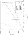
Figure 1 shows a force-displacement graph of various bulk materials; -
Figure 2 shows a perspective view of a representative implant; -
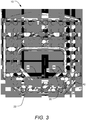
Figure 3 shows a top view of the implant ofFigure 2 ; -
Figure 4 shows a perspective view of various coil packs for use with implants; -
Figure 5 shows a cross-sectional view of an illustrative coil pack; -
Figure 6 shows a perspective view of illustrative adjacent coil packs having clockwise and counter-clockwise sweep directions; and -
Figure 7 shows a perspective view of illustrative alternate coil packs. - A description of embodiments of the present invention will now be given with reference to the Figures. It is expected that the present invention may take many other forms and shapes, hence the following disclosure is intended to be illustrative and not limiting, and the scope of the invention should be determined by reference to the appended claims.
- Embodiments of the invention provide orthopedic implants, particularly implemented in the current examples as interbody spacers, the implants having a combination of correct pore size and stiffness/flexibility. Embodiments of the invention also provide methods for producing such orthopedic implants. When the implants have the proper pore size and stiffness, osteocytes are able to properly bridge the pores of the implant and then experience a proper compressive load to stimulate the bone cells to form bone within the pores throughout the implants according to Wolff's law.
- According to embodiments of the invention, an implant includes a body formed of an osteoconductive material. The body may have a stiffness of between 400 megapascals (MPa) and 1,200 MPa. Additionally, the body may include a plurality of pores having an average size of between 150 microns and 600 microns. The pores may be interconnected and permit the growth of bone therein. The implant may be an interbody spacer.
- The osteoconductive material may be any of a variety of materials such as titanium, tantalum, and alloys thereof or titanium and alloys thereof such as, for example Ti 6-4 (approximately 6% aluminum, 4% vanadium, up to 0.25% iron, up to 0.2% oxygen and the remainder titanium) and other recognized alloys used for implants. Alternatively, the osteoconductive material may be any material now known or later discovered to be biocompatible and osteoconductive and providing characteristics in line with those discussed herein. In certain embodiments, the implant has a stiffness of between 600 MPa and 1,000 MPa. In other embodiments, the implant has a stiffness of between 750 MPa and 850 MPa. In still other embodiments, the implant has a stiffness of between 950 MPa and 1,050 MPa. In additional embodiments, the implant has a stiffness of between 750 MPa and 1,050 MPa.
- The implant may be manufactured using an additive manufacturing process. The implant may have a coil spring construction. The coil spring construction may have a vertical spacing between coils of between 250 microns and 350 microns. The coil spring construction may have a coil diameter of between 400 microns and 600 microns. The implant may have a nested coil spring construction. The implant may also or alternatively have a plurality of overlapping coil packs. Where present, the plurality of overlapping coil packs may include coils that are connected and coils that are intertwined without connecting. The implant may have a plurality of coil springs joined in clockwise to counter-clockwise sweep directions.
- According to alternate embodiments of the invention, an implant includes a body comprising a plurality of coil springs formed of an osteoconductive material. The body may have a stiffness of between 400 MPa and 1,200 MPa. The body may also include a plurality of pores having an average size of between 150 microns and 600 microns.
- The osteoconductive material may be any of a variety of materials such as titanium, tantalum, and alloys thereof or titanium and alloys thereof. Alternatively, the osteoconductive material may be any material now known or later discovered to be biocompatible and osteoconductive and providing characteristics in line with those discussed herein. In certain embodiments, the implant has a stiffness of between 600 MPa and 1,000 MPa. In other embodiments, the implant has a stiffness of between 750 MPa and 850 MPa. In still other embodiments, the implant has a stiffness of between 950 MPa and 1,050 MPa. In additional embodiments, the implant has a stiffness of between 750 MPa and 1,050 MPa.
- The implant may be manufactured using an additive manufacturing process. The coil springs of the body may have a vertical spacing between coils of between 250 microns and 350 microns. The coil springs of the body may have a coil diameter of between 400 microns and 600 microns. The implant may have a nested coil spring construction. The implant may also or alternatively have a plurality of overlapping coil packs. Where present, the plurality of overlapping coil packs may include coils that are connected and coils that are intertwined without connecting. The implant may have a plurality of coil springs joined in clockwise to counter-clockwise sweep directions.
- According to alternate embodiments of the invention, an implant includes a body comprising a plurality of coil springs manufactured using an additive manufacturing process. The coil springs may be arranged into a plurality of overlapping coil packs having coils that are connected and coils that are intertwined without connecting. The coil springs may include coils having a clockwise sweep direction and coils having a counterclockwise sweep direction. The body may have a stiffness of between 400 MPa and 1,200 MPa. The body may have a plurality of pores having an average size of between 150 microns and 600 microns.
- The osteoconductive material may be any of a variety of materials such as titanium, tantalum, and alloys thereof or titanium and alloys thereof. Alternatively, the osteoconductive material may be any material now known or later discovered to be biocompatible and osteoconductive and providing characteristics in line with those discussed herein. In certain embodiments, the implant has a stiffness of between 600 MPa and 1,000 MPa. In other embodiments, the implant has a stiffness of between 750 MPa and 850 MPa. In still other embodiments, the implant has a stiffness of between 950 MPa and 1,050 MPa. In additional embodiments, the implant has a stiffness of between 750 MPa and 1,050 MPa.
- The coil springs of the body may have a vertical spacing between coils of between 250 microns and 350 microns. The coil springs of the body may have a coil diameter of between 400 microns and 600 microns. The implant may have a nested coil spring construction.
- According to further embodiments of the invention, a method of manufacturing an implant includes a step of forming an implant body using an additive manufacturing process. The step of forming an implant body may include forming a plurality of coils of an osteoconductive material. The coils so formed may have a vertical coil spacing and a coil diameter chosen to impart certain physical characteristics to the implant while facilitating use of the additive manufacturing process. The implant body so formed may have a stiffness of between 400 MPa and 1,200 MPa, and may include a plurality of pores having an average size of between 150 microns and 600 microns.
- In certain embodiments, the implant body so formed has a stiffness of between 600 MPa and 1,000 MPa. In other embodiments, the implant body so formed has a stiffness of between 750 MPa and 850 MPa. In still other embodiments, the implant body so formed has a stiffness of between 950 MPa and 1,050 MPa. In additional embodiments, the implant body so formed has a stiffness of between 750 MPa and 1,050 MPa.
- The coil springs of the body may have a vertical spacing between coils of between 250 microns and 350 microns. The coil springs of the body may have a coil diameter of between 400 microns and 600 microns. The implant may have a nested coil spring construction.
- The implant so formed may have a nested coil spring construction. The implant may also or alternatively have a plurality of overlapping coil packs. Where present, the plurality of overlapping coil packs may include coils that are connected and coils that are intertwined without connecting. The implant may have a plurality of coil springs joined in clockwise to counter-clockwise sweep directions.
- As discussed above, it would be ideal for an implant to provide porosity and stiffness generally similar to actual bone using materials that are conducive to bone growth. In addition to an ideal pore size of 150 microns to 650 microns, an ideal implant would have a stiffness of between 400 MPa and 1.2 gigapascals (GPa) (1,200 MPa). Additionally, when pores are at the larger end of the ideal range, the implant will allow for the fastest and greatest extent of vascularization. Bones that experience larger loads generally have smaller pores and greater stiffness. To grow denser, stronger bone requires an implant with upper-range pore sizes and lower-range stiffness to allow the bone to experience more of the load. In this way, the implant avoids shielding bone within the implant from stress that would cause the bone to grow. Additionally, the larger pores allow the bone to better occupy the available space.
-
Figure 1 shows a force-displacement graph of various materials, illustrating the stiffness of the various materials. The line with the steepest slope and thus greatest stiffness is bulk titanium. As shown inFigure 1 , the next stiffest materials are PEEK and trabecular metal (tantalum). In contrast, the stiffness of trabecular bone (shown as exhibiting a range of stiffnesses due to the varying stiffness of different areas of trabecular bone in the body) is still significantly less than even trabecular metal. In contrast, a "tranquility" implant in accordance with embodiments of the invention, though made from titanium or a titanium alloy in this example, achieves a stiffness near the lower end of the stiffness range of trabecular bone. As will be described further below, the exact configuration of coil springs, including coil spacing, etc., in the implant can be varied to achieve varying implant stiffnesses while achieving a desired pore size - something that cannot be achieved with other implant systems. -
Figure 2 shows a perspective view of anillustrative implant 10 demonstrating features in accordance with embodiments of the invention.Figure 3 shows a top view of theillustrative implant 10. The illustrative implant includes a plurality of two types of coil packs arranged in an alternating arrangement. In the alternating arrangement, afirst coil pack 12 having a clockwise sweep direction alternates with asecond coil pack 14 having a counterclockwise sweep direction. Eachcoil pack Figures 2 and3 , eachcoil pack -
Figure 4 illustrates how illustrative coil packs may be formed of one or more spring coils.Figure 4 illustrates three different exemplary coil packs. The left coil pack includes a single spring coil, namelyfirst spring coil 30. The central coil pack includes two spring coils, namelyfirst spring coil 30 andsecond spring coil 32. In this central example, the spring coils 30, 32 are concentric in that they have a common axis about which eachspring coil first spring coil 30 and thesecond spring coil 32. Alternatively, if desired, the wire diameter and/or coil diameter of thefirst spring coil 30 may differ from the wire diameter and/or coil diameter of thesecond spring coil 32 if desired to impart different stiffness or other characteristics to theimplant 10 in which the coil pack is incorporated. - In any coil pack embodiment, the vertical spacing, wire diameter, and/or coil diameter may be varied as desired to vary the stiffness and other characteristics of the
implant 10 in which the coil pack is incorporated. For example, in comparing the left coil pack ofFigure 4 to the middle coil pack ofFigure 4 , it may be seen that the total number of wire turns in each example is similar, even though the turns of the central example are split between two spring coils while the turns of the left example are formed from a single spring coil. In each example ofFigure 4 , the wire diameter and coil diameter is similar. The stiffness of each example is varied by the differing coil pitches achieved by having two spring coils as opposed to a single spring coil. -
Figure 4 includes a third example of a coil pack on the right side. This example is formed of four spring coils, namelyfirst spring coil 30,second spring coil 32,third spring coil 34, andfourth spring coil 36. This example further illustrates that the number of spring coils forming each spring pack may be varied as desired, and it will be a matter of straightforward experimentation with varied numbers of spring coils, spring wire thickness, and vertical coil spacing to achieve a desired stiffness of each coil pack. In each of the coil packs ofFigure 4 , the spring coils (and the coil packs themselves) have a clockwise sweep direction. Essentially identical coil packs may be formed having counter-clockwise sweep direction, even though such are not illustrated inFigure 4 . - The spring coils of each coil pack may assume any desired cross-sectional shape. For example,
Figure 5 shows a cross-sectional view of a four-wire coil pack formed offirst spring coil 30,second spring coil 32,third spring coil 34, andfourth spring coil 36. In this example, the wire of each spring coil has a square cross-sectional shape with radiused edges, but essentially any cross-sectional shape may be used. For example, the spring coils may have a round cross-sectional shape, an elliptical cross-sectional shape, a square cross-sectional shape, a rectangular cross-sectional shape, or a cross-sectional shape of any desired number of sides (pentagonal, octagonal, etc.), with or without rounded or radiused edges. Further examples of illustrative shapes and configurations of spring coils and coil packs are shown inFigure 7 , as discussed below. - The coil pack or swept coil of each coil pack has a stiffness and strength that depends on the base diameter of the coil pack, which can be chosen to facilitate bone growth. The stiffness and strength are also dependent on the pitch of the coils in the coil pack, which can further be chosen to facilitate bone growth by defining a proper size space between coils. The stiffness and strength are also dependent on the wire diameter and modulus of rigidity of the chosen material. When coils are placed together to form coil packs, the needed pore spacing for bone growth is created while the bulk strength is increased and the bulk stiffness of the device is decreased.
- Forming the body of the
implant 10 as coil packs 12, 14 allows an additive manufacturing process to be used with traditionally biocompatible and osteoconductive materials (e.g. titanium and alloys thereof) while still maintaining a desired stiffness. Additionally, this type of construction allows the additive manufacturing process to be used while still achieving the desired pore size. Traditionally, additive manufacturing processes were incapable of being used to provide the desired pore size. Specifically, the pores of prior devices were conceived in negative, thus limiting the pore size to the minimum feature size of the additive manufacturing process, which in turn determines the bulk stiffness (typically much higher than the stiffness of trabecular bone). - Using the coil pack construction discussed herein allows for the creation of pores by stacking overlapping geometry. In effect, the overlapping geometry allows the pore size to be smaller and better shaped without reducing the minimum feature size of the additive manufacturing process. While the smaller pore size achieved in this way would traditionally increase stiffness, the clever geometry of the coil packs allows the bulk flexibility to be increased as governed by the following equation:

- In this way, the
implant 10 may have a micro-porous structure effectively formed of flexible micro struts that in concert decrease the bulk stiffness of the device, allowing for use of osteoconductive materials such as Ti 6-4, tantalum, or other alloys of titanium or tantalum. The pore size thus achieved is large enough for vascularization and rapid bone growth, and not too large for bone bridging, and the bone is able to grow both on and throughout the device. The contact area between the device and the bone can be increased, mitigating overloading of local bone at the bone-to-device interface. - As illustrated in
Figures 2 and3 , the coil packs 12, 14 may be arranged in a way so as to overlap/intersect. This overlapping/intersecting of clockwise and counter-clockwise sweeping coil packs is illustrated in more detail inFigure 6 . In this Figure, a full set of coil packs is shown at the left, and the right shows what may either be an entire set of coil packs, or merely a single set of spring coils from the coil pack at the left ofFigure 6 . In the left illustrated example ofFigure 6 , thefirst coil pack 12 has four individual spring coils, namely,first spring coil 30,second spring coil 32,third spring coil 34 andfourth spring coil 36, all having a clockwise sweep direction, while thesecond coil pack 14 has three individual spring coils, namely,first spring coil 40,second spring coil 42, andthird spring coil 44. Thus, thefirst coil pack 12 has an additional spring coil,fourth spring coil 36 that is unpaired and has no corresponding spring coil in thesecond coil pack 14. This may be by design to decrease stiffness of theimplant 10 containing the joined coil packs 12, 14. - As may be seen in Figure 16, and particularly in the single-spring-coil example at the right of
Figure 6 , the individual spring coils of eachcoil pack implant 10 is formed in the additive manufacturing process, the individual coils of the coil pack are unitarily formed such that while the coils of the coil packs may be conceptually viewed as separate coils, they are actually united in a way that provides a measure of overall structure to theimplant 10. Additionally, this construction overcomes limitations of the additive manufacturing process, allowing for creation of the ideal pore size. This type of construction effectively avoids the additive manufacturing process's limitations, as the additive manufacturing process views each spring coil as an independent structure. The overlapping coil packs have the added advantages of tailored shear stiffness and strength as well as load sharing between adjacent coil packs. - The top view of the
implant 10 shown inFigure 3 illustrates how the coils of adjacent coil packs are joined at one cross-sectional point, namely, the top surface of theimplant 10. In this Figure, thethird spring coil 34 of one of the first coil packs 12 is joined to thethird spring coil 44 of one of the second coil packs 14. Thesecond spring coil 32 of thatfirst coil pack 12 is joined to thesecond spring coil 42 of a differentsecond coil pack 14, and thefirst spring coil 30 of thatfirst coil pack 12 is joined to thefirst spring coil 40 of yet another differentsecond coil pack 14. Thus eachcoil pack implant 10 as a unitary, though relatively flexible body. - If desired, the
implant 10 may include some areas of additional structure, rigidity, and strength at locations where the normal increased flexibility is not needed or is not desired. For example, theimplant 10 shown inFigures 2 and3 may include anouter bottom rim 20, an inner bottom rim (not shown) an outertop rim 22, and an innertop rim 24. The innertop rim 24 and the inner bottom rim may define top and bottom edges of a void adapted to receive a bone graft material such as morcellized bone (living bone) prior to implantation of theimplant 10, thereby providing a seed to better initiate bone growth into theimplant 10 after implantation, as is known in the art. Additionally, theimplant 10 may include arigid strut 26 formed on one side of theimplant 10, if it is determined that theimplant 10 should be more rigid on one side thereof. - As discussed above, the cross-sectional form of each coil spring may be varied, and the configuration of the coil packs may also take other forms as long as they achieve the purposes discussed herein. To this end,
Figure 7 illustrates alternate embodiments of coil packs that could be used with embodiments of theimplant 10. The left coil pack ofFigure 7 includesfirst spring coil 30,second spring coil 32,third spring coil 34, andfourth spring coil 36, as did one of the examples ofFigure 4 . In this example, however, the spring coils 30, 32, 34, and 36 have a non-rounded square cross-sectional profile. - In the right coil pack of
Figure 7 , the coil pack includes afirst diamond structure 50 and asecond diamond structure 52, illustrating that the coil packs need not be formed solely of standard sweep coils, but that coil packs may be formed of any microstructure that is capable of being manufactured using an additive manufacturing process while providing a proper pore size and bulk stiffness. The interlocking diamond shape of the right coil pack ofFigure 7 achieves this in a different fashion than the coil packs illustrated and discussed previously, but still provides an interlocking structure and a known small pore size within the constraints of existing additive manufacturing processes. - The illustrated implant embodiment of
Figures 2 and3 is an interbody spacer aimed at facilitating bony fusion of adjacent segments of the spine. Theimplant 10 can be placed in an intervertebral space to provide support to the spine during bone growth, but furthermore can work to promote and stimulate bone growth. Unlike prior devices, theimplant 10 can simultaneously promote and stimulate bone growth throughout the device (not just onto the surface of the device) while maintaining stable support. - It is envisioned that the systems and methods illustrated herein may be useful in other types of orthopedic implants, and that the stiffness and pore sizes may be modified as appropriate to achieve the desired characteristics at the location where such implants are to be used.
- The present invention may be embodied in other specific forms without departing from essential characteristics. The described embodiments are to be considered in all respects only as illustrative and not restrictive. The scope of the invention is, therefore, indicated by the appended claims, rather than by the foregoing description. All changes which come within the meaning and range of equivalency of the claims are to be embraced within their scope.
Claims (15)
- An implant (10) comprising:a body comprising a plurality of coil springs (30, 32, 40, 42) formed of an osteoconductive material;the body comprising a stiffness of between 400 megapascals (MPa) and 1,200 MPa; andthe body comprising a plurality of pores having an average size of between 150 microns and 600 microns.
- An implant according to claim 1, wherein the osteoconductive material comprises a material selected from the group consisting of titanium, tantalum, and alloys thereof.
- An implant according to claim 1, wherein the osteoconductive material comprises a material selected from the group consisting of titanium and alloys thereof.
- An implant according to claim 1, wherein the implant comprises a stiffness of between 600 MPa and 1,000 MPa.
- An implant according to claim 1, wherein the implant comprises a stiffness of between 750 MPa and 850 MPa.
- An implant according to claim 1 wherein the implant comprises a stiffness of between 950 MPa and 1,050 MPa.
- An implant according to claim 1, wherein the implant is manufactured using an additive manufacturing process.
- An implant according to claim 1, wherein the coil spring construction comprises a vertical spacing between coils of between 250 microns and 350 microns.
- An implant according to claim 1, wherein the coil spring construction comprises a coil diameter of between 400 microns and 600 microns.
- An implant according to claim 1, wherein the implant comprises a nested coil spring construction.
- An implant according to claim 1, wherein the implant comprises a plurality of overlapping coil packs.
- An implant according to claim 11, wherein the plurality of overlapping coil packs comprise coils that are connected and coils that are intertwined without connecting.
- An implant according to claim 1, wherein the implant comprises a plurality of coil springs joined in clockwise to counter-clockwise sweep directions.
- An implant according to claim 13, wherein the plurality of coil springs comprises coils that are connected and coils that are intertwined without connecting.
- An implant according to claim 13, wherein the implant is an interbody spacer.
Applications Claiming Priority (3)
| Application Number | Priority Date | Filing Date | Title |
|---|---|---|---|
| US201562264217P | 2015-12-07 | 2015-12-07 | |
| US201662355789P | 2016-06-28 | 2016-06-28 | |
| PCT/US2016/065452 WO2017100366A1 (en) | 2015-12-07 | 2016-12-07 | Porous interbody spacer |
Publications (3)
| Publication Number | Publication Date |
|---|---|
| EP3386444A1 EP3386444A1 (en) | 2018-10-17 |
| EP3386444A4 EP3386444A4 (en) | 2019-07-31 |
| EP3386444B1 true EP3386444B1 (en) | 2020-11-18 |
Family
ID=58800090
Family Applications (1)
| Application Number | Title | Priority Date | Filing Date |
|---|---|---|---|
| EP16873797.1A Active EP3386444B1 (en) | 2015-12-07 | 2016-12-07 | Porous interbody spacer |
Country Status (4)
| Country | Link |
|---|---|
| US (1) | US20170156880A1 (en) |
| EP (1) | EP3386444B1 (en) |
| AU (1) | AU2016366191B2 (en) |
| WO (1) | WO2017100366A1 (en) |
Families Citing this family (58)
| Publication number | Priority date | Publication date | Assignee | Title |
|---|---|---|---|---|
| US20180228621A1 (en) | 2004-08-09 | 2018-08-16 | Mark A. Reiley | Apparatus, systems, and methods for the fixation or fusion of bone |
| US10363140B2 (en) | 2012-03-09 | 2019-07-30 | Si-Bone Inc. | Systems, device, and methods for joint fusion |
| US11147688B2 (en) | 2013-10-15 | 2021-10-19 | Si-Bone Inc. | Implant placement |
| US9662157B2 (en) * | 2014-09-18 | 2017-05-30 | Si-Bone Inc. | Matrix implant |
| US10449051B2 (en) * | 2015-04-29 | 2019-10-22 | Institute for Musculoskeletal Science and Education, Ltd. | Implant with curved bone contacting elements |
| JP6768001B2 (en) * | 2015-04-29 | 2020-10-14 | インスティテュート フォー マスキュロスケレタル サイエンス アンド エジュケイション,リミテッド | Coiled implants and systems and how to make them |
| US10492921B2 (en) | 2015-04-29 | 2019-12-03 | Institute for Musculoskeletal Science and Education, Ltd. | Implant with arched bone contacting elements |
| US10709570B2 (en) | 2015-04-29 | 2020-07-14 | Institute for Musculoskeletal Science and Education, Ltd. | Implant with a diagonal insertion axis |
| WO2018031801A1 (en) * | 2016-08-11 | 2018-02-15 | Amnon Yadin | Intervertebral disc replacement |
| US20190254840A1 (en) | 2016-09-16 | 2019-08-22 | Mirus Llc | Interbody fusion devices and related methods of manufacture |
| US10478312B2 (en) | 2016-10-25 | 2019-11-19 | Institute for Musculoskeletal Science and Education, Ltd. | Implant with protected fusion zones |
| US11033394B2 (en) | 2016-10-25 | 2021-06-15 | Institute for Musculoskeletal Science and Education, Ltd. | Implant with multi-layer bone interfacing lattice |
| US10357377B2 (en) | 2017-03-13 | 2019-07-23 | Institute for Musculoskeletal Science and Education, Ltd. | Implant with bone contacting elements having helical and undulating planar geometries |
| US10512549B2 (en) | 2017-03-13 | 2019-12-24 | Institute for Musculoskeletal Science and Education, Ltd. | Implant with structural members arranged around a ring |
| GB2561293A (en) * | 2017-03-14 | 2018-10-10 | Alphatec Spine Inc | Intervertebral Cage with porosity gradient |
| KR101806140B1 (en) * | 2017-06-29 | 2017-12-15 | 주식회사 멘티스로지텍 | Spinal implant with unit structure printed 3d printer |
| WO2019051260A1 (en) | 2017-09-08 | 2019-03-14 | Pioneer Surgical Technology, Inc. | Intervertebral implants, instruments, and methods |
| WO2019067584A1 (en) | 2017-09-26 | 2019-04-04 | Si-Bone Inc. | Systems and methods for decorticating the sacroiliac joint |
| USD907771S1 (en) | 2017-10-09 | 2021-01-12 | Pioneer Surgical Technology, Inc. | Intervertebral implant |
| CN107790719B (en) * | 2017-11-13 | 2018-09-11 | 成都优材科技有限公司 | Based on selective laser molten metal fine cellular structure forming method |
| US10940015B2 (en) | 2017-11-21 | 2021-03-09 | Institute for Musculoskeletal Science and Education, Ltd. | Implant with improved flow characteristics |
| US10744001B2 (en) | 2017-11-21 | 2020-08-18 | Institute for Musculoskeletal Science and Education, Ltd. | Implant with improved bone contact |
| US11039933B2 (en) * | 2017-12-15 | 2021-06-22 | Innovasis, Inc. | Interbody spinal fusion implant with support struts |
| USD870890S1 (en) | 2018-03-02 | 2019-12-24 | Restor3D, Inc. | Spiral airway stent |
| USD870888S1 (en) | 2018-03-02 | 2019-12-24 | Restor3D, Inc. | Accordion airway stent |
| US10183442B1 (en) | 2018-03-02 | 2019-01-22 | Additive Device, Inc. | Medical devices and methods for producing the same |
| USD870889S1 (en) | 2018-03-02 | 2019-12-24 | Restor3D, Inc. | Cutout airway stent |
| USD871577S1 (en) | 2018-03-02 | 2019-12-31 | Restor3D, Inc. | Studded airway stent |
| WO2019173778A1 (en) | 2018-03-08 | 2019-09-12 | Nexus Spine, LLC | Stand-alone interbody fusion |
| US11583413B2 (en) * | 2018-03-08 | 2023-02-21 | Nexus Spine, L.L.C. | Expanding interbody spacers |
| US10682238B2 (en) | 2018-05-08 | 2020-06-16 | Globus Medical, Inc. | Intervertebral spinal implant |
| US10744003B2 (en) | 2018-05-08 | 2020-08-18 | Globus Medical, Inc. | Intervertebral spinal implant |
| US10555819B2 (en) | 2018-05-08 | 2020-02-11 | Globus Medical, Inc. | Intervertebral spinal implant |
| CN210644254U (en) * | 2018-06-12 | 2020-06-02 | 深圳市立心科学有限公司 | Intervertebral fusion device with buffer part |
| US11534305B2 (en) | 2018-09-26 | 2022-12-27 | Nexus Spine, L.L.C. | Expanding, conforming interbody spacer |
| CN109481092A (en) * | 2018-12-04 | 2019-03-19 | 北京市春立正达医疗器械股份有限公司 | Trabecular bone structure and the prosthese for applying it |
| US11039931B2 (en) | 2019-02-01 | 2021-06-22 | Globus Medical, Inc. | Intervertebral spinal implant |
| US11369419B2 (en) | 2019-02-14 | 2022-06-28 | Si-Bone Inc. | Implants for spinal fixation and or fusion |
| WO2020168269A1 (en) | 2019-02-14 | 2020-08-20 | Si-Bone Inc. | Implants for spinal fixation and or fusion |
| US10889053B1 (en) | 2019-03-25 | 2021-01-12 | Restor3D, Inc. | Custom surgical devices and method for manufacturing the same |
| US11273048B2 (en) * | 2019-09-25 | 2022-03-15 | Mirus Llc | Interbody lattice structure |
| EP3809232B1 (en) * | 2019-10-19 | 2024-04-24 | Goodrich Corporation | Pressure-regulating valve |
| EP4065015A4 (en) | 2019-11-27 | 2024-01-03 | Si Bone Inc | Bone stabilizing implants and methods of placement across si joints |
| USD920515S1 (en) | 2020-01-08 | 2021-05-25 | Restor3D, Inc. | Spinal implant |
| USD920517S1 (en) | 2020-01-08 | 2021-05-25 | Restor3D, Inc. | Osteotomy wedge |
| USD920516S1 (en) | 2020-01-08 | 2021-05-25 | Restor3D, Inc. | Osteotomy wedge |
| US10772732B1 (en) | 2020-01-08 | 2020-09-15 | Restor3D, Inc. | Sheet based triply periodic minimal surface implants for promoting osseointegration and methods for producing same |
| US11707361B2 (en) * | 2020-02-05 | 2023-07-25 | K2M, Inc. | Flexible interbody implant |
| DE102020103015A1 (en) * | 2020-02-06 | 2021-08-12 | Aesculap Ag | Intervertebral implant |
| US11957600B2 (en) | 2020-02-18 | 2024-04-16 | Mirus Llc | Anterior lumbar interbody fusion device with bidirectional screws |
| USD942623S1 (en) | 2020-11-13 | 2022-02-01 | Mirus Llc | Spinal implant |
| USD942624S1 (en) | 2020-11-13 | 2022-02-01 | Mirus Llc | Spinal implant |
| USD944400S1 (en) | 2020-11-13 | 2022-02-22 | Mirus Llc | Spinal implant |
| USD942011S1 (en) | 2020-11-13 | 2022-01-25 | Mirus Llc | Spinal implant |
| JP2023553120A (en) | 2020-12-09 | 2023-12-20 | エスアイ-ボーン・インコーポレイテッド | Sacroiliac joint stabilization implants and implant methods |
| US11850144B1 (en) | 2022-09-28 | 2023-12-26 | Restor3D, Inc. | Ligament docking implants and processes for making and using same |
| US11806028B1 (en) | 2022-10-04 | 2023-11-07 | Restor3D, Inc. | Surgical guides and processes for producing and using the same |
| US11960266B1 (en) | 2023-08-23 | 2024-04-16 | Restor3D, Inc. | Patient-specific medical devices and additive manufacturing processes for producing the same |
Family Cites Families (17)
| Publication number | Priority date | Publication date | Assignee | Title |
|---|---|---|---|---|
| SE391122B (en) * | 1971-01-25 | 1977-02-07 | Cutter Lab | PROTESTS IN THE FORM OF A SPINE BONIC DISC AND PROCEDURES FOR MANUFACTURE THEREOF |
| US4309777A (en) * | 1980-11-13 | 1982-01-12 | Patil Arun A | Artificial intervertebral disc |
| US6296664B1 (en) * | 1998-06-17 | 2001-10-02 | Surgical Dynamics, Inc. | Artificial intervertebral disc |
| US20020128714A1 (en) * | 1999-06-04 | 2002-09-12 | Mark Manasas | Orthopedic implant and method of making metal articles |
| US6827743B2 (en) * | 2001-02-28 | 2004-12-07 | Sdgi Holdings, Inc. | Woven orthopedic implants |
| BR0313499A (en) | 2002-08-15 | 2005-07-05 | David Gerber | Intervertebral disc |
| JP2006528515A (en) * | 2003-07-24 | 2006-12-21 | テコメット・インコーポレーテッド | Spongy structure |
| AU2003257319A1 (en) * | 2003-08-08 | 2005-02-25 | Biorthex Inc. | Biocompatible porous ti-ni material |
| US7309357B2 (en) * | 2004-12-30 | 2007-12-18 | Infinesse, Corporation | Prosthetic spinal discs |
| US7517228B2 (en) * | 2005-12-22 | 2009-04-14 | Intel Corporation | Surface mounted micro-scale springs for separable interconnection of package substrate and high-speed flex-circuit |
| US8298286B2 (en) * | 2006-12-19 | 2012-10-30 | Warsaw Orthopedic, Inc. | Non-linear vertebral mesh |
| EP1961433A1 (en) * | 2007-02-20 | 2008-08-27 | National University of Ireland Galway | Porous substrates for implantation |
| EP2280666A4 (en) | 2008-04-04 | 2013-07-03 | Thomas Haider Patents | Intervertebral prostheses with compliant filler material for supporting adjacent vertebral bodies and method |
| JP2013528067A (en) * | 2010-05-11 | 2013-07-08 | アラーガン、インコーポレイテッド | Porogen materials, manufacturing methods, and uses |
| WO2016061148A1 (en) * | 2014-10-16 | 2016-04-21 | Additive Innovations, Llc | Additive manufactured titanium bone device |
| JP6768001B2 (en) * | 2015-04-29 | 2020-10-14 | インスティテュート フォー マスキュロスケレタル サイエンス アンド エジュケイション,リミテッド | Coiled implants and systems and how to make them |
| US10390959B2 (en) * | 2015-11-24 | 2019-08-27 | Agada Medical Ltd. | Intervertebral disc replacement |
-
2016
- 2016-12-07 AU AU2016366191A patent/AU2016366191B2/en active Active
- 2016-12-07 US US15/372,290 patent/US20170156880A1/en not_active Abandoned
- 2016-12-07 WO PCT/US2016/065452 patent/WO2017100366A1/en active Application Filing
- 2016-12-07 EP EP16873797.1A patent/EP3386444B1/en active Active
Non-Patent Citations (1)
| Title |
|---|
| None * |
Also Published As
| Publication number | Publication date |
|---|---|
| EP3386444A1 (en) | 2018-10-17 |
| WO2017100366A1 (en) | 2017-06-15 |
| EP3386444A4 (en) | 2019-07-31 |
| US20170156880A1 (en) | 2017-06-08 |
| AU2016366191B2 (en) | 2019-10-03 |
| AU2016366191A1 (en) | 2018-06-21 |
Similar Documents
| Publication | Publication Date | Title |
|---|---|---|
| EP3386444B1 (en) | Porous interbody spacer | |
| JP7301111B2 (en) | Porous spinal fusion implant | |
| US11944552B2 (en) | Stand-alone interbody fusion | |
| US10405983B2 (en) | Implant with independent endplates | |
| US20200297505A1 (en) | Internal Bone Fixation Device | |
| EP1779812A1 (en) | An osseointegration implant | |
| US20130030531A1 (en) | Radiolucent Spinal Fusion Cage | |
| US20050177238A1 (en) | Radiolucent bone graft | |
| US20190117410A1 (en) | Porous implantable interbody devices | |
| CN111529144B (en) | Self-adaptive intervertebral fusion device | |
| CN111839832B (en) | Intervertebral fusion device with multiple buffer units | |
| WO2014140916A2 (en) | Intervertebral fusion implant cage | |
| CN108670507B (en) | Self-adaptive intervertebral fusion device | |
| CN208910605U (en) | Fusion device | |
| US20180353302A1 (en) | Adjustable, Implantable Spinal Disc Device for Deformity Correction in Intervertebral Fusion Procedures | |
| CN210250170U (en) | Oblique side interbody fusion cage | |
| EP1477190A1 (en) | Porous block of metallic spheres for growing bone tissue on the inside | |
| CN210250171U (en) | Anterior cervical interbody fusion cage | |
| CN210204992U (en) | Lumbar vertebrae side way interbody fusion cage | |
| CN209437430U (en) | Fusion device | |
| CN210277414U (en) | Intervertebral fusion device with buffer part |
Legal Events
| Date | Code | Title | Description |
|---|---|---|---|
| STAA | Information on the status of an ep patent application or granted ep patent |
Free format text: STATUS: THE INTERNATIONAL PUBLICATION HAS BEEN MADE |
|
| PUAI | Public reference made under article 153(3) epc to a published international application that has entered the european phase |
Free format text: ORIGINAL CODE: 0009012 |
|
| STAA | Information on the status of an ep patent application or granted ep patent |
Free format text: STATUS: REQUEST FOR EXAMINATION WAS MADE |
|
| 17P | Request for examination filed |
Effective date: 20180706 |
|
| AK | Designated contracting states |
Kind code of ref document: A1 Designated state(s): AL AT BE BG CH CY CZ DE DK EE ES FI FR GB GR HR HU IE IS IT LI LT LU LV MC MK MT NL NO PL PT RO RS SE SI SK SM TR |
|
| AX | Request for extension of the european patent |
Extension state: BA ME |
|
| DAV | Request for validation of the european patent (deleted) | ||
| DAX | Request for extension of the european patent (deleted) | ||
| A4 | Supplementary search report drawn up and despatched |
Effective date: 20190701 |
|
| RIC1 | Information provided on ipc code assigned before grant |
Ipc: A61F 2/30 20060101ALI20190625BHEP Ipc: A61F 2/00 20060101ALI20190625BHEP Ipc: A61B 17/70 20060101ALI20190625BHEP Ipc: A61F 2/44 20060101AFI20190625BHEP |
|
| GRAP | Despatch of communication of intention to grant a patent |
Free format text: ORIGINAL CODE: EPIDOSNIGR1 |
|
| STAA | Information on the status of an ep patent application or granted ep patent |
Free format text: STATUS: GRANT OF PATENT IS INTENDED |
|
| INTG | Intention to grant announced |
Effective date: 20200616 |
|
| RAP1 | Party data changed (applicant data changed or rights of an application transferred) |
Owner name: NEXUS SPINE, L.L.C. |
|
| GRAS | Grant fee paid |
Free format text: ORIGINAL CODE: EPIDOSNIGR3 |
|
| GRAA | (expected) grant |
Free format text: ORIGINAL CODE: 0009210 |
|
| STAA | Information on the status of an ep patent application or granted ep patent |
Free format text: STATUS: THE PATENT HAS BEEN GRANTED |
|
| AK | Designated contracting states |
Kind code of ref document: B1 Designated state(s): AL AT BE BG CH CY CZ DE DK EE ES FI FR GB GR HR HU IE IS IT LI LT LU LV MC MK MT NL NO PL PT RO RS SE SI SK SM TR |
|
| REG | Reference to a national code |
Ref country code: GB Ref legal event code: FG4D |
|
| REG | Reference to a national code |
Ref country code: CH Ref legal event code: EP |
|
| REG | Reference to a national code |
Ref country code: IE Ref legal event code: FG4D |
|
| REG | Reference to a national code |
Ref country code: DE Ref legal event code: R096 Ref document number: 602016048324 Country of ref document: DE |
|
| REG | Reference to a national code |
Ref country code: AT Ref legal event code: REF Ref document number: 1334918 Country of ref document: AT Kind code of ref document: T Effective date: 20201215 |
|
| REG | Reference to a national code |
Ref country code: AT Ref legal event code: MK05 Ref document number: 1334918 Country of ref document: AT Kind code of ref document: T Effective date: 20201118 |
|
| REG | Reference to a national code |
Ref country code: NL Ref legal event code: MP Effective date: 20201118 |
|
| PG25 | Lapsed in a contracting state [announced via postgrant information from national office to epo] |
Ref country code: FI Free format text: LAPSE BECAUSE OF FAILURE TO SUBMIT A TRANSLATION OF THE DESCRIPTION OR TO PAY THE FEE WITHIN THE PRESCRIBED TIME-LIMIT Effective date: 20201118 Ref country code: GR Free format text: LAPSE BECAUSE OF FAILURE TO SUBMIT A TRANSLATION OF THE DESCRIPTION OR TO PAY THE FEE WITHIN THE PRESCRIBED TIME-LIMIT Effective date: 20210219 Ref country code: PT Free format text: LAPSE BECAUSE OF FAILURE TO SUBMIT A TRANSLATION OF THE DESCRIPTION OR TO PAY THE FEE WITHIN THE PRESCRIBED TIME-LIMIT Effective date: 20210318 Ref country code: RS Free format text: LAPSE BECAUSE OF FAILURE TO SUBMIT A TRANSLATION OF THE DESCRIPTION OR TO PAY THE FEE WITHIN THE PRESCRIBED TIME-LIMIT Effective date: 20201118 Ref country code: NO Free format text: LAPSE BECAUSE OF FAILURE TO SUBMIT A TRANSLATION OF THE DESCRIPTION OR TO PAY THE FEE WITHIN THE PRESCRIBED TIME-LIMIT Effective date: 20210218 |
|
| PG25 | Lapsed in a contracting state [announced via postgrant information from national office to epo] |
Ref country code: AT Free format text: LAPSE BECAUSE OF FAILURE TO SUBMIT A TRANSLATION OF THE DESCRIPTION OR TO PAY THE FEE WITHIN THE PRESCRIBED TIME-LIMIT Effective date: 20201118 Ref country code: BG Free format text: LAPSE BECAUSE OF FAILURE TO SUBMIT A TRANSLATION OF THE DESCRIPTION OR TO PAY THE FEE WITHIN THE PRESCRIBED TIME-LIMIT Effective date: 20210218 Ref country code: LV Free format text: LAPSE BECAUSE OF FAILURE TO SUBMIT A TRANSLATION OF THE DESCRIPTION OR TO PAY THE FEE WITHIN THE PRESCRIBED TIME-LIMIT Effective date: 20201118 Ref country code: IS Free format text: LAPSE BECAUSE OF FAILURE TO SUBMIT A TRANSLATION OF THE DESCRIPTION OR TO PAY THE FEE WITHIN THE PRESCRIBED TIME-LIMIT Effective date: 20210318 Ref country code: PL Free format text: LAPSE BECAUSE OF FAILURE TO SUBMIT A TRANSLATION OF THE DESCRIPTION OR TO PAY THE FEE WITHIN THE PRESCRIBED TIME-LIMIT Effective date: 20201118 Ref country code: SE Free format text: LAPSE BECAUSE OF FAILURE TO SUBMIT A TRANSLATION OF THE DESCRIPTION OR TO PAY THE FEE WITHIN THE PRESCRIBED TIME-LIMIT Effective date: 20201118 |
|
| REG | Reference to a national code |
Ref country code: LT Ref legal event code: MG9D |
|
| PG25 | Lapsed in a contracting state [announced via postgrant information from national office to epo] |
Ref country code: HR Free format text: LAPSE BECAUSE OF FAILURE TO SUBMIT A TRANSLATION OF THE DESCRIPTION OR TO PAY THE FEE WITHIN THE PRESCRIBED TIME-LIMIT Effective date: 20201118 |
|
| PG25 | Lapsed in a contracting state [announced via postgrant information from national office to epo] |
Ref country code: SK Free format text: LAPSE BECAUSE OF FAILURE TO SUBMIT A TRANSLATION OF THE DESCRIPTION OR TO PAY THE FEE WITHIN THE PRESCRIBED TIME-LIMIT Effective date: 20201118 Ref country code: RO Free format text: LAPSE BECAUSE OF FAILURE TO SUBMIT A TRANSLATION OF THE DESCRIPTION OR TO PAY THE FEE WITHIN THE PRESCRIBED TIME-LIMIT Effective date: 20201118 Ref country code: CZ Free format text: LAPSE BECAUSE OF FAILURE TO SUBMIT A TRANSLATION OF THE DESCRIPTION OR TO PAY THE FEE WITHIN THE PRESCRIBED TIME-LIMIT Effective date: 20201118 Ref country code: EE Free format text: LAPSE BECAUSE OF FAILURE TO SUBMIT A TRANSLATION OF THE DESCRIPTION OR TO PAY THE FEE WITHIN THE PRESCRIBED TIME-LIMIT Effective date: 20201118 Ref country code: SM Free format text: LAPSE BECAUSE OF FAILURE TO SUBMIT A TRANSLATION OF THE DESCRIPTION OR TO PAY THE FEE WITHIN THE PRESCRIBED TIME-LIMIT Effective date: 20201118 Ref country code: LT Free format text: LAPSE BECAUSE OF FAILURE TO SUBMIT A TRANSLATION OF THE DESCRIPTION OR TO PAY THE FEE WITHIN THE PRESCRIBED TIME-LIMIT Effective date: 20201118 |
|
| REG | Reference to a national code |
Ref country code: CH Ref legal event code: PL |
|
| REG | Reference to a national code |
Ref country code: DE Ref legal event code: R097 Ref document number: 602016048324 Country of ref document: DE |
|
| PG25 | Lapsed in a contracting state [announced via postgrant information from national office to epo] |
Ref country code: MC Free format text: LAPSE BECAUSE OF FAILURE TO SUBMIT A TRANSLATION OF THE DESCRIPTION OR TO PAY THE FEE WITHIN THE PRESCRIBED TIME-LIMIT Effective date: 20201118 Ref country code: DK Free format text: LAPSE BECAUSE OF FAILURE TO SUBMIT A TRANSLATION OF THE DESCRIPTION OR TO PAY THE FEE WITHIN THE PRESCRIBED TIME-LIMIT Effective date: 20201118 |
|
| REG | Reference to a national code |
Ref country code: BE Ref legal event code: MM Effective date: 20201231 |
|
| PLBE | No opposition filed within time limit |
Free format text: ORIGINAL CODE: 0009261 |
|
| STAA | Information on the status of an ep patent application or granted ep patent |
Free format text: STATUS: NO OPPOSITION FILED WITHIN TIME LIMIT |
|
| 26N | No opposition filed |
Effective date: 20210819 |
|
| PG25 | Lapsed in a contracting state [announced via postgrant information from national office to epo] |
Ref country code: IE Free format text: LAPSE BECAUSE OF NON-PAYMENT OF DUE FEES Effective date: 20201207 Ref country code: AL Free format text: LAPSE BECAUSE OF FAILURE TO SUBMIT A TRANSLATION OF THE DESCRIPTION OR TO PAY THE FEE WITHIN THE PRESCRIBED TIME-LIMIT Effective date: 20201118 Ref country code: NL Free format text: LAPSE BECAUSE OF FAILURE TO SUBMIT A TRANSLATION OF THE DESCRIPTION OR TO PAY THE FEE WITHIN THE PRESCRIBED TIME-LIMIT Effective date: 20201118 Ref country code: IT Free format text: LAPSE BECAUSE OF FAILURE TO SUBMIT A TRANSLATION OF THE DESCRIPTION OR TO PAY THE FEE WITHIN THE PRESCRIBED TIME-LIMIT Effective date: 20201118 Ref country code: LU Free format text: LAPSE BECAUSE OF NON-PAYMENT OF DUE FEES Effective date: 20201207 |
|
| PG25 | Lapsed in a contracting state [announced via postgrant information from national office to epo] |
Ref country code: LI Free format text: LAPSE BECAUSE OF NON-PAYMENT OF DUE FEES Effective date: 20201231 Ref country code: CH Free format text: LAPSE BECAUSE OF NON-PAYMENT OF DUE FEES Effective date: 20201231 Ref country code: SI Free format text: LAPSE BECAUSE OF FAILURE TO SUBMIT A TRANSLATION OF THE DESCRIPTION OR TO PAY THE FEE WITHIN THE PRESCRIBED TIME-LIMIT Effective date: 20201118 |
|
| PG25 | Lapsed in a contracting state [announced via postgrant information from national office to epo] |
Ref country code: ES Free format text: LAPSE BECAUSE OF FAILURE TO SUBMIT A TRANSLATION OF THE DESCRIPTION OR TO PAY THE FEE WITHIN THE PRESCRIBED TIME-LIMIT Effective date: 20201118 |
|
| PG25 | Lapsed in a contracting state [announced via postgrant information from national office to epo] |
Ref country code: IS Free format text: LAPSE BECAUSE OF FAILURE TO SUBMIT A TRANSLATION OF THE DESCRIPTION OR TO PAY THE FEE WITHIN THE PRESCRIBED TIME-LIMIT Effective date: 20210318 Ref country code: TR Free format text: LAPSE BECAUSE OF FAILURE TO SUBMIT A TRANSLATION OF THE DESCRIPTION OR TO PAY THE FEE WITHIN THE PRESCRIBED TIME-LIMIT Effective date: 20201118 Ref country code: MT Free format text: LAPSE BECAUSE OF FAILURE TO SUBMIT A TRANSLATION OF THE DESCRIPTION OR TO PAY THE FEE WITHIN THE PRESCRIBED TIME-LIMIT Effective date: 20201118 Ref country code: CY Free format text: LAPSE BECAUSE OF FAILURE TO SUBMIT A TRANSLATION OF THE DESCRIPTION OR TO PAY THE FEE WITHIN THE PRESCRIBED TIME-LIMIT Effective date: 20201118 |
|
| PG25 | Lapsed in a contracting state [announced via postgrant information from national office to epo] |
Ref country code: MK Free format text: LAPSE BECAUSE OF FAILURE TO SUBMIT A TRANSLATION OF THE DESCRIPTION OR TO PAY THE FEE WITHIN THE PRESCRIBED TIME-LIMIT Effective date: 20201118 |
|
| PG25 | Lapsed in a contracting state [announced via postgrant information from national office to epo] |
Ref country code: BE Free format text: LAPSE BECAUSE OF NON-PAYMENT OF DUE FEES Effective date: 20201231 |
|
| P01 | Opt-out of the competence of the unified patent court (upc) registered |
Effective date: 20230527 |
|
| PGFP | Annual fee paid to national office [announced via postgrant information from national office to epo] |
Ref country code: GB Payment date: 20231121 Year of fee payment: 8 |
|
| PGFP | Annual fee paid to national office [announced via postgrant information from national office to epo] |
Ref country code: FR Payment date: 20231122 Year of fee payment: 8 Ref country code: DE Payment date: 20231121 Year of fee payment: 8 |