EP3386270B1 - Induction heating method and system - Google Patents
Induction heating method and system Download PDFInfo
- Publication number
- EP3386270B1 EP3386270B1 EP17164842.1A EP17164842A EP3386270B1 EP 3386270 B1 EP3386270 B1 EP 3386270B1 EP 17164842 A EP17164842 A EP 17164842A EP 3386270 B1 EP3386270 B1 EP 3386270B1
- Authority
- EP
- European Patent Office
- Prior art keywords
- actuation frequency
- current
- actuation
- sequence
- value
- Prior art date
- Legal status (The legal status is an assumption and is not a legal conclusion. Google has not performed a legal analysis and makes no representation as to the accuracy of the status listed.)
- Active
Links
Images


Classifications
-
- H—ELECTRICITY
- H05—ELECTRIC TECHNIQUES NOT OTHERWISE PROVIDED FOR
- H05B—ELECTRIC HEATING; ELECTRIC LIGHT SOURCES NOT OTHERWISE PROVIDED FOR; CIRCUIT ARRANGEMENTS FOR ELECTRIC LIGHT SOURCES, IN GENERAL
- H05B6/00—Heating by electric, magnetic or electromagnetic fields
- H05B6/02—Induction heating
- H05B6/06—Control, e.g. of temperature, of power
- H05B6/062—Control, e.g. of temperature, of power for cooking plates or the like
-
- H—ELECTRICITY
- H05—ELECTRIC TECHNIQUES NOT OTHERWISE PROVIDED FOR
- H05B—ELECTRIC HEATING; ELECTRIC LIGHT SOURCES NOT OTHERWISE PROVIDED FOR; CIRCUIT ARRANGEMENTS FOR ELECTRIC LIGHT SOURCES, IN GENERAL
- H05B2213/00—Aspects relating both to resistive heating and to induction heating, covered by H05B3/00 and H05B6/00
- H05B2213/04—Heating plates with overheat protection means
Definitions
- the present invention generally relates to the field of induction heating. More specifically, the present invention relates to monitoring heating during induction heating.
- Induction heating is a well-known method for heating an electrically conducting load by inducing eddy currents in the load through a time-varying magnetic field generated by an alternating current (hereinafter, simply AC current) flowing in an induction heating coil.
- the internal resistance of the load causes the induced eddy currents to generate heat in the load itself.
- Induction heating is used in the field of induction cooking, particularly in induction ovens, induction cooktops and induction hobs.
- induction hob induction heating coils are located under a cooking hob surface for heating cooking pans made (or including portions) of electrically ferromagnetic material placed on the cooking hob surface.
- the amount of heat generated in the load depends on the electric power delivered to the load through the induction heating coil, which in turn depends on the frequency of the AC current flowing through the latter, the coupling between the load and the induction heating coil, and the time spent by the load at the induction heating coil.
- the AC current used to generate the time-varying magnetic field is generated by means of an inverter circuit, such as a half bridge inverter, a full bridge inverter, or a quasi-resonant inverter, comprising a switching section including power switching elements, such as for example Insulated-Gate Bipolar Transistors (IGBT), and a resonant section comprising inductor(s) and capacitor(s), with the induction heating coil that is an inductor of the latter section.
- IGBT Insulated-Gate Bipolar Transistors
- the inverter circuit is configured to receive an input alternating voltage (hereinafter, simply AC voltage), such as the mains voltage taken from the power grid, and to accordingly generate an AC current (flowing through the induction heating coil) oscillating at a frequency corresponding to actuation frequency of the power switching elements (i.e ., the frequency with which they are switched between the on and the off state) and having an envelope following the input AC voltage, with the amplitude of the envelope that depends in turn on the actuation frequency itself (the lower the actuation frequency, the higher the amplitude thereof).
- the current flowing through the induction heating coil is sourced/drained by the power switching elements of the switching section.
- the electric power delivered to the load through the induction heating coil depends on the frequency of the AC current flowing through the latter.
- the electric power provided to the load is at its maximum when the current flowing through the induction heating coil oscillates at the resonance frequency of the resonant section, i.e., when the actuation frequency is equal to the resonance frequency.
- the electric power delivered to the load strongly depends on the coupling between the induction heating coil and the load, i.e., it depends from a series of unpredictable features such as the type of load, the distance between load and induction heating coil, the geometry of the load and of the induction heating coil.
- unpredictable features such as the type of load, the distance between load and induction heating coil, the geometry of the load and of the induction heating coil.
- the resonance frequency strongly depends on the coupling between the induction heating coil and the load, i.e., it depends from a series of unpredictable features such as the type of load, the distance between load and induction heating coil, the geometry of the load and of the induction heating coil.
- Devices which exploit induction heating should be provided with a control unit specifically designed to carry out dynamic measurements so as to obtain an indication about how the actuation frequency and the electric power delivered to the load are related to each other.
- control unit When a user of a device of this kind is requesting a specific electric power (e.g ., corresponding to a specific temperature to be reached by a cooking pan), such control unit has to carry out measurements to assess the actuation frequency/electric power relation corresponding to the actual condition (e.g ., corresponding to the actual coupling between the induction heating coil and the load); then, the control unit is configured to dispense the requested electric power by setting the actuation frequency according to the assessed actuation frequency/electric power relation.
- actuation frequency/electric power relation corresponding to the actual condition
- the control unit is configured to dispense the requested electric power by setting the actuation frequency according to the assessed actuation frequency/electric power relation.
- control unit may be configured to set the electric power to a safe level different from the requested one.
- the envelope of the AC current flowing through the induction heating coil has an amplitude that depends on the actuation frequency (the lower the actuation frequency, the higher the amplitude thereof), it is not possible to known a priori whether a selected actuation frequency corresponds to a current flowing through the induction heating coil that is lower than the maximum current or not.
- EP 1734789 A1 discloses a method involving providing an alternating supply voltage and a frequency converter with an adjustable switching unit.
- the operating frequency of the switching unit and/or the frequency converter is increased from a frequency base in the course of half cycle of the voltage.
- the frequency is then decreased to the base, so that the frequency amounts to the base, at the zero crossing of the supply voltage.
- WO 2016/041684 A1 there is disclosed an induction hob having a vibrational sensor for detecting audible sound generated when substances are boiling on the heating zones of the induction hob. Taking into consideration signals received from the vibrational sensor, the controller of the induction hob may control the cooking process, such as by lowering the power supplied to the respective heating zone, so as to avoid overboiling or to provide for simmering of the food articles being cooked at a constant cooking temperature.
- EP 1732357 A2 discloses a method for monitoring the cooking temperature in an induction hob, in which method the frequency of alternating current flowing through the inductor is set to a fixed value, and an electrical parameter of the hob is monitored, which is correlated to the power of the inductor, such as coil current.
- the method described in EP 1732357 A2 has several disadvantages, such as that during the measuring process the power supply has to be set to a predetermined power level which may substantially differ from the power level that corresponds to the temperature selected by the use.
- WO 2013/064332 A1 there is disclosed a method for boiling detection in an induction heating system as it is defined in the pre-characterizing portion of claim 1 and an induction heating system as it is defined in the pre-characterizing portion of claim 12.
- Applicant has observed that it would be advantageous to provide an induction heating system with a control unit which has the capability of rapidly obtaining an indication about how the actuation frequency and the electric power delivered to the load are related to each other in the actual condition (e.g., corresponding to the actual coupling between the induction heating coil and the load), wherein by evaluating the amount of electric power delivered to the load the temperature variation of the load can be determined.
- a control unit which has the capability of rapidly obtaining an indication about how the actuation frequency and the electric power delivered to the load are related to each other in the actual condition (e.g., corresponding to the actual coupling between the induction heating coil and the load), wherein by evaluating the amount of electric power delivered to the load the temperature variation of the load can be determined.
- the present invention in a first aspect, is a method for managing an induction heating system as it is defined in claim 1.
- the induction heating system comprises an electrically conducting load and an inverter circuit comprising a switching section and a resonant section.
- the switching section comprises switching devices adapted to generate an AC current from an AC input voltage comprising a plurality of half-waves.
- the resonant section comprises an induction heating coil adapted to receive the AC current for generating a corresponding time-varying magnetic field in order to generate heat in the electrically conducting load by inductive coupling.
- the AC current oscillates at an actuation frequency of the switching devices and has an envelope comprising a plurality of half-waves corresponding to the half-waves of the AC input voltage.
- the amount of heat generated in the load depends on the frequency of the AC current.
- the method comprises performing at least once a sequence of steps in which:
- the above procedure preferably is carried out either continuously for a predetermined duration, during which a number of consecutive measurements is made, or is repeated at a certain frequency, such as every 3 seconds until boiling is detected.
- the method suggested herein can be performed any time during operation of the induction heating system, such as during heating up the heating element by providing electric power to the heating element, or at a point in time when the power delivery is turned off.
- the procedure of varying the actuation frequency is effected within a single half-wave of the envelope, and hence only a very short time is required to carry out these procedures, such frequency scan provides for minimal interference with the power delivery to the heating element. Therefore, the method suggested herein when carried out during heating up the heating element does noticeably prolongate the heating procedure, because the power delivery at the optimum activation frequency is interrupted only for a very short time.
- the method also may be carried out when the power delivery is turned off, such as when the heating element has been heated to a selected temperature and thus the power delivery is interrupted until the temperature of the heating element has fallen below a predetermined margin. Given the short time needed to carry out the present method, the power delivered during the frequency scan is so small that it does not provide for noticeable heating.
- the present invention is an induction heating system for heating an electrically conducting load as it is defined in claim 12.
- a boiling condition is determined when variations in the current peak/actuation frequency relations are less than a predetermined minimum value. While in the "ideal" case boiling is detected when there is no variation and thus the incline of the relation of current peak to actuation frequency has decreased to zero, in order to allow for measuring inaccuracies a boiling condition can be assumed when the variations in the current peak/actuation frequency relations fall within a certain minimum range.
- the method further comprises averaging variations in the current peak/actuation frequency relations generated for plural actuation frequencies, and determining a boiling condition when a thus obtained average variation in the current peak/actuation frequency relations is less than a predetermined minimum value.
- a boiling condition is determined when said variation or said average variation is less than a predetermined minimum value in a predetermined number of subsequent time increments, in each of which the sequence of steps (a) to (c) is performed.
- the method may comprise considering a subset of the overall current peak/actuation frequency relations generated for plural actuation frequencies, and determining a boiling condition when at least one variation in the said subset is less than a predetermined minimum value.
- a boiling condition can be determined when the variation in any selected number of these relations is less than a predetermined minimum value. That is, assuming that for example 10 frequencies are evaluated, a boiling condition can be assumed when for example a minimum of for example 4 of the 10 current peak/actuation frequency curves exhibit a plateau in which the variations, i.e. the slope of the curves, falls below a predetermined minimum value.
- a mean value can be determined from all or selected of the relations that are determined.
- a further option to avoid or minimize the effects of noise in the determined relations is to determine the variations in the individual relations and provide for weighing the variations. Thus, for example by introducing a weight that is inversely proportional to the noise, those relations can be neglected that exhibit the largest variations.
- said sequence of actuation frequency values comprises a first sequence portion starting from a first actuation frequency value and then proceeding with lower actuation frequency values at every time interval corresponding to a fraction of the duration of the half-wave of the envelope.
- said sequence of actuation frequency values preferably comprises a second sequence portion starting from the last actuation frequency value of the first sequence portion and then proceeding with higher actuation frequency values at every time interval corresponding to a fraction of the duration of the half-wave of the envelope.
- said sequence of actuation frequency values comprises a first sequence portion starting from a first actuation frequency value and then proceeding with higher actuation frequency values at every time interval corresponding to a fraction of the duration of the half-wave of the envelope.
- said sequence of actuation frequency values preferably comprises a second sequence portion starting from the last actuation frequency value of the first sequence portion and then proceeding with lower actuation frequency values at every time interval corresponding to a fraction of the duration of the half-wave of the envelope.
- said step of varying, within a same half-wave of the envelope, the actuation frequency comprises setting each new actuation frequency value of the sequence except the first one based on the distance of the previous actuation frequency value in the sequence with respect to the actual resonance frequency.
- said phase of calculating, for each actuation frequency value of the sequence, the corresponding current peak value can comprise normalizing each one of the absolute value peaks of the corresponding set of at least one absolute value peak according to the position of the corresponding time interval with respect to said half-wave to obtain a corresponding set of at least one normalised current peak value, and then calculating the peak value based on the normalised current peak values of the set.
- the step of calculating the peak value based on the normalised current peak values of the set can comprise calculating an average value of said at least two absolute value peaks.
- said inverter circuit can be selected one among:
- the induction heating system of the present invention may be part of any inducting heating system that is designed to heat a food item, such as an induction oven, wherein said electrically conducting load is an induction shelf and said induction heating coil is mounted along a bottom, top or sidewall of said induction oven, or a cooking hob, in which said induction heating coil is mounted below a cooking plate or zone and said electrically conducting load is a portion of a cooking pan or pot, or a water heater, wherein said electrically conducting load is a water tank and said induction heating coil is mounted below the tank.
- a food item such as an induction oven
- said electrically conducting load is an induction shelf and said induction heating coil is mounted along a bottom, top or sidewall of said induction oven, or a cooking hob, in which said induction heating coil is mounted below a cooking plate or zone and said electrically conducting load is a portion of a cooking pan or pot, or a water heater, wherein said electrically conducting load is a water tank and said induction heating coil
- Figure 1 illustrates an exemplary induction cooking system 100 wherein the concepts of the solution according to embodiments of the invention can be applied.
- the induction cooking system 100 comprises a (e.g ., glass-ceramic) cooking surface 165.
- a number of induction coils 135 are placed underneath the cooking surface 165.
- the induction coils 135 are selectively operable for defining one or more cooking zones 170, wherein plural individual cooking zones 170 also may be combined into a combined cooking zone 190.
- each induction coil 135 is selectively operable to be fed with AC current provided by a respective inverter circuit 140.
- the inverter circuit(s) 140 causes an AC current to flow through the (one or more) respective induction coil(s) 135.
- This current flow generates a time-varying magnetic field 145, which is capable of inducing eddy currents in the cooking pan 180 (or in the portions thereof made of ferromagnetic material).
- the induced eddy currents cause the cooking pan 180 (or the portions thereof made of ferromagnetic material) to rapidly heat up to a desired working temperature.
- the thermal energy lost by contact with the (non-illustrated) food contained in the cooking pan 180 is replaced continuously by the current provided by the inverter circuit 140.
- the induction cooking system 100 comprises a control unit 160 configured to control the inverter circuits 140 in order to regulate the frequency of the AC current flowing in the induction coils 135 in such a way to regulate the electric power transferred from the generic inverter circuit 140 to the corresponding cooking pan 180, and therefore, the temperature of the latter.
- Figure 2A is an exemplary circuit diagram of an inverter circuit 140 for feeding AC current to an induction coil 135 of the induction cooking system 100 wherein the concepts of the solution according to embodiments of the invention can be applied.
- the inverter circuit 140 is a half-bridge inverter circuit, however similar considerations apply in case different types of inverter circuits arrangements are used, such as a full-bridge inverter circuit or a quasi-resonant inverter circuit.
- the inverter circuit 140 comprises two main sections: a switching section 205 and a resonant section 210.
- the switching section 205 comprises two insulated-gate bipolar transistors (IGBT) 212h, 2121 connected in series between the line terminal 215 and the neutral terminal 220 of the power grid.
- An input AC voltage Vin (the mains voltage) develops between the line terminal 215 and the neutral terminal 220, oscillating at a mains frequency Fm , such as 50 Hz.
- the IGBT 212h has a collector terminal connected to the line terminal 215, a gate terminal for receiving a control signal A1, and an emitter terminal connected to the collector terminal of the IGBT 2121, defining a circuit node 222 therewith.
- the IGBT 2121 has an emitter terminal connected to neutral terminal 220 and a gate terminal for receiving a control signal A2.
- the control signals A1 and A2 are digital periodic signals oscillating at a same frequency, hereinafter referred to as actuation frequency Fa, between a high value and a low value, with a mutual phase difference of 180°, so that when the IGBT 212h is turned on, the IGBT 2121 is turned off, and vice versa. Similar considerations apply if different types of electronic switching devices are employed in place of IGBTs.
- the resonant section 210 comprises the induction coil 135 and two resonance capacitors 225, 230.
- the resonance capacitor 225 has a first terminal connected to the collector terminal of the IGBT 212h and a second terminal connected to a first terminal of the resonance capacitor 230, defining a circuit node 223 therewith.
- the resonance capacitor 230 has a second terminal connected to the emitter terminal of the IGBT 2121.
- the induction heating coil 135 is connected between circuit nodes 222 and 223.
- the current Ic flowing through the induction heating coil 135 is alternatively sourced by the IGBT 212h (when the IGBT 212h is on and the IGBT 2121 is off) and drained by the IGBT 2121 (when the IGBT 212h is off and the IGBT 2121 is on).
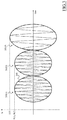
- the induction heating coil current Ic oscillates at the actuation frequency Fa, and has an envelope 300 that follows the input AC voltage Vin, i.e., it comprises a plurality of half waves 310(i), each one corresponding to a respective half wave of the input AC voltage Vin and therefore having a duration equal to the semiperiod of the input AC voltage Vin ( i.e ., 1/(2* Fm )) .
- the induction heating coil current Ic returns to zero (if an actuation with a suitable load is performed).
- the envelope 300 has an amplitude that depends on the actuation frequency Fa : the lower the actuation frequency Fa , the higher the amplitude.
- the portion of the envelope 300 of the induction heating coil current Ic illustrated in Figure 3 has three half waves 310(1), 310(2), 310(3), each one having a corresponding amplitude E(1), E(2), E(3).
- the first two half waves 310(1), 310(2) of the envelope 300 correspond to an actuation frequency Fa higher than the one corresponding to the third half wave 310(3). Therefore, the amplitude E(3) of the third half wave 310(3) is higher than the one of the first two half waves 310(1), 310(2).
- an inverter circuit 140 of the quasi-resonant type such as the one illustrated in Figure 2B , comprising a rectifier 250 (for example, a bridge rectifier) adapted to rectify the input AC voltage Vin, a quasi-resonant circuit 260 (for example comprising an inductor in parallel to a capacitor) corresponding to the resonant section 210 of the half-bridge inverter circuit 140 of Figure 2A , and a switching circuit 270 (for example comprising a single transistor) corresponding to the switching section 205 of the half-bridge inverter circuit 140 of Figure 2A .
- a rectifier 250 for example, a bridge rectifier
- a quasi-resonant circuit 260 for example comprising an inductor in parallel to a capacitor
- switching circuit 270 for example comprising a single transistor
- the actuation frequency Fa should be set higher than the resonance frequency Fr.
- the actuation frequency Fa should be set higher than the current limit frequency Fc, as will be explained in further detail below.
- the control unit 160 when the temperature setting provided by the user of the cooking system 100 involves the request of a specific amount of electric power to be delivered, the control unit 160 is configured to check whether such electric power request corresponds to an actuation frequency Fa which falls within a safe frequency range.
- control unit 160 advantageously is configured to dynamically (i.e., during the operation of the cooking system 100) determine, or at least assess, the resonance frequency Fr as well as the current limit frequency Fc, or checking whether a certain actuation frequency range is a safe range (in the sense that the above-mentioned frequency limits are respected). In this way, account is taken of the fact that both the resonance frequency Fr and the current limit frequency Fc strongly depend on the actual coupling between the cooking pan 180 and the induction heating coil 135.
- a preliminary inspection phase can be carried out ( i.e., before the actual power delivery phase) in which the actuation frequency Fa is varied step by step according to a sequence of predetermined actuation frequency values, with each actuation frequency value of the sequence that is maintained for a respective half wave (or also more than one consecutive half waves) of the envelope of the AC voltage Vin.
- known resonance identification procedures such as by measuring the distance between the zero crossing time of the induction heating coil current Ic and the zero crossing time of the induction heating coil voltage, a check is made during each half wave of the envelope of the AC voltage Vin to evaluate the closeness of the corresponding actuation frequency value to the resonance frequency Fr.
- actuation frequency is varied within a single half-wave.
- the power delivery phase may be immediately initiated by setting the actuation frequency Fa step by step, with each actuation frequency value of the sequence that is maintained for a respective half wave of the envelope of the AC voltage Vin, starting from a safe (e.g., high) actuation frequency value, and continuing until the desired power value is reached or until a frequency close to the resonance frequency Fr is reached (if the latter actuation frequency occurs prior the one corresponding to desired power value) .
- a safe e.g., high
- a possible method may provide for varying the actuation frequency step by step according to a sequence of (decreasing) predetermined actuation frequency values, with each actuation frequency value of the sequence that is maintained for a respective half wave of the envelope of the AC voltage Vin, until the limit is reached. Then, the value taken by the actuation frequency during the half wave of the envelope of the AC voltage Vin in which the maximum current is approached is identified as the current limit frequency Fc, i.e. the minimum actuation frequency value for which the AC current Ic flowing through the induction heating coil is lower than the maximum current that can be sustained (for a relatively prolonged) by the power switching elements.
- the maximum peak current value is advantageously measured within the corresponding half wave of the envelope of the AC voltage Vin, so as to be able to construct an induction heating coil current characteristic curve, expressing how the maximum peak current varies in function of the actuation frequency.
- the coupling between the load (i.e ., the cooking pan 180) and the induction heating coil 135 may change in a very fast way (e.g ., within 0.1-0.5 sec), which is not compatible with the time required by the inspection methods mentioned above.
- the load-coil coupling may change every time the position of the cooking pan 180 changes with respect to the position of the induction heating coil 135. Therefore, the inspection methods mentioned above may not be efficient from the power delivery point of view.
- the induction heating system employed in the present invention preferably is designed such that when the temperature setting provided by the user of the cooking system 100 involves the request of a specific amount of electric power Pt to be delivered, the control unit 160 is configured to dynamically carry out an actuation frequency selection procedure adapted to asses a value Fa* of the actuation frequency Fa that corresponds to the requested electric power Pt.
- control unit 160 is configured to actually set the frequency of the AC current flowing in the induction coils 135 (i.e ., the actuation frequency Fa ) taking into consideration the assessed value Fa* , in such a way to regulate the delivered electric power according to the request of the user.
- a preferred actuation frequency selection procedure comprises a first phase in which the control unit 160 varies step by step the actuation frequency Fa of the control signals A1, A2 according to a sequence of actuation frequency values TFa(j) within a same half wave 310(i) of the envelope 300 of the current Ic, for measuring corresponding peak values of the induction heating coil current Ic to generate a corresponding actuation frequency/current peak relation.
- the first phase is initiated by the control unit 160 by setting the actuation frequency Fa to the first actuation frequency value TFa(1) of the sequence as soon as a half-wave 310(i) of the envelope 300 of the induction heating coil current Ic is initiated.
- This can be detected by assessing the zero crossing time of the input AC voltage Vin (which identifies the beginning of a half-wave 310(i) of the envelope 300) through a proper zero voltage crossing circuit (not illustrated).
- the following actuation frequency values TFa(j) of the sequence are then set step by step by the control unit 160 within the same half-wave 310(i) of the envelope 300.
- the control unit 160 measures corresponding peak values of the induction heating coil current Ic.
- the sequence of actuation frequency values TFa(j) is a predefined sequence, for example stored in the control unit itself 160 in form of tables or defined by means of a mathematic relationship, such as for example "decreasing by an amount X multiplied by a factor related to the distance from the resonance frequency Fr " .
- control unit 160 is configured to assess whether the frequency range spanned by the sequence of actuation frequency values TFa(j) is a safe actuation frequency range for the operation of the system by taking into consideration the closeness of each actuation frequency value TFa(j) of the sequence to the resonance frequency Fr ( e.g., by calculating for each actuation frequency value TFa(j) the distance between the zero crossing time of the induction heating coil voltage and the zero crossing time of the induction heating coil current Ic).
- the control unit 160 is aware of the possibility to set (for power delivery) the actuation frequency Fa to any value comprised in said actuation frequency range without incurring in the risk of reaching and going below the resonance frequency Fr.
- the control unit 160 cannot freely set the actuation frequency Fa to any value comprised in said actuation frequency range, because at least a portion of such actuation frequency range comprises frequencies which are lower than the resonance frequency Fr.
- control unit 160 may select a safe actuation frequency subrange from the spanned frequency range based on the closeness of the actuation frequency values TFa(j) of the sequence to the resonance frequency Fr, such as for example by setting a lower boundary for such subrange equal to or higher than the actuation frequency value TFa(j) which has been assessed to be the closest one to the resonance frequency Fr.
- Figures 4A and 4B illustrate the evolution in time of the actuation frequency Fa of the control signals A1, A2 set by the control unit 160 during a procedure as may be used in the method suggested herein following two exemplary different predefined sequences of actuation frequency values TFa(j).
- the predefined sequence of actuation frequency values TFa(j) provides for starting from a first actuation frequency value TFa(1), then proceeding with lower and lower actuation frequency values TFa(j) every time interval tj equal to a fraction of the semiperiod of the input AC voltage Vin (and therefore equal to a fraction of the duration of the half wave 310(i) of the envelope 300), until substantially reaching the centre of the half wave 310(i); then, the predefined sequence of actuation frequency values TFa(j) provides for proceeding with higher and higher actuation frequency values TFa(j) every time interval tj until reaching the end of the half wave 310(i).
- tj may be equal to 0,3 msec.
- the evolution in time of the actuation frequency Fa comprises a decreasing ramp followed by an increasing ramp.
- the predefined sequence of actuation frequency values TFa(j) provides for starting from a first actuation frequency value TFa(1), then proceeding with higher and higher actuation frequency values TFa(j) every time interval tj equal to a fraction of the semiperiod of the input AC voltage Vin (and therefore equal to a fraction of the duration of the half wave 310(i) of the envelope 300), until substantially reaching the centre of the half wave 310(i); then, the predefined sequence of actuation frequency values TFa(j) provides for proceeding with lower and lower actuation frequency values TFa(j) every time interval tj until reaching the end of the half wave 310(i).
- the evolution in time of the actuation frequency Fa comprises an increasing ramp followed by a decreasing ramp.
- the higher actuation frequency value TFa(j) of the sequence i.e., the one corresponding to substantially the centre of the half wave 310(i)
- the procedure can be configured such that as soon as the control unit 160 assesses that an actuation frequency value TFa(j) results to be very close to the resonance frequency Fr (e.g., when the distance between the zero crossing time of the induction heating coil voltage and the zero crossing time of the induction heating coil current Ic is lower than a safe threshold), the actuation frequency Fa is clamped to said actuation frequency value TFa(j) (or also to a higher value) for the rest of the half-wave 310(i), or for more than one subsequent half-waves for allowing a fast high power delivery, or even for the rest of the half-wave in which the user has requested a power corresponding to a lower actuation frequency.
- each new actuation frequency value TFa(j) in the sequence also can be dynamically calculated by the control unit 160 based, for instance, on the distance of the previous actuation frequency value TFa(j) in the sequence with respect to the actual resonance frequency Fr (wherein said distance may be evaluated according to one of the previously mentioned methods). In this way, it is possible to refine the resonance frequency Fr search when in the proximity of the resonance frequency Fr itself.
- An example of a sequence of actuation frequency values TFa(j) calculated in a dynamic way is illustrated in Figure 4C .
- the actuation frequency can be dynamically adjusted to provide for a temperature control which precisely reflects a temperature setting selected by the user of the induction cooking system 100, in the following the procedure for boiling detection in accordance with the present invention will be explained in detail.
- Figure 5 there is illustrated an example of an actuation frequency profile as may be employed in the method suggested herein, wherein the profile shown in Figure 5 is symmetric about a minimum frequency similar as that shown in Figure 4A , but wherein the frequency is varied from step to step not in a constant fashion as in Figure 4A , but is dynamically varied similarly as the in the profile shown Figure 4C .
- the distance among the actuation frequency values TFa(j) of the sequence with respect to the actual resonance frequency Fr can be evaluated by calculating the power factor cos ⁇ corresponding to the induction coil 135 (the closer the power factor cos ⁇ to 1, the closer the actuation frequency value TFa(j) to the resonance frequency Fr ).
- the inverter circuit 140 may be provided with a clamping circuit (not illustrated) configured to clamp the induction heating coil current Ic when it reaches the maximum current that can be sustained by the IGBTs 212h, 212l. Additionally, or alternatively, a software protection may be provided, configured to clamp the actuation frequency Fa of the control signals A1, A2 before the induction heating coil current Ic reaches the maximum current that can be sustained by the IGBTs 212h, 212l.
- the procedure for assessing the safe actuation frequency range having regard to current limit frequency Fc can be carried out by the control unit 160 by varying step by step the actuation frequency Fa of the control signals A1, A2 in the same way as for the procedure for assessing the safe actuation frequency range having regard to resonance frequency, i.e., according to a sequence of actuation frequency values TFa(j) within a same half wave 310(i) of the envelope 300 of the current Ic, until a condition of maximum allowable current is approached, requiring to clamp the actuation frequency Fa to an actuation frequency value TFa(j) corresponding to an induction heating coil current Ic value close to the maximum current that can be sustained by the IGBTs 212h, 2121, or until a suitable range of actuation frequencies TFa(j) is explored.
- the considerations about the sequence of actuation frequency values TFa(j) carried out for the procedure for assessing the safe actuation frequency range having regard to the resonance frequency apply as well to the procedure for
- control unit 160 measures at each j-th step of the sequence:
- Figure 6 illustrates, as a result of a test performed by the Applicant, a current peak/actuation (i.e. time) relation of the positive peaks Pk + and the negative peaks Pk - measured by the control unit 160 with respect to time during an actuation frequency Fa step by step variation within an half wave 310(i) of the envelope 300.
- the normalised positive and negative peaks Pk + , Pk - can be obtained by modifying each corresponding positive and negative peak Pk + , Pk - according to the position of the time interval tj of the measure with respect to the half wave 310(i).
- the normalised positive and negative peaks Pk + COMP , Pk - COMP are obtained by modifying each corresponding positive and negative peak Pk + , Pk - through ( e.g ., by multiplying them by) an expansion coefficient ec(j) whose value depends on the position of the time interval tj of the measure with respect to the half wave 310(i).
- such expansion coefficient can be selected such that the more the time interval tj is far from the centre of the half wave 310(i), the higher the expansion coefficient ec(j) .
- the position of the time interval tj with respect to the half wave 310(i) can be determined by measuring the value of the input AC voltage Vin during the time interval tj.
- An estimation of the current limit frequency Fc can be calculated by taking into account the actuation frequency value TFa(j) which is the one whose corresponding normalised positive or negative peak Pk + COMP , Pk - COMP is the closest one to the maximum current that can be sustained by the IGBTs 212h, 212l.
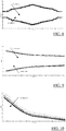
- Figure 10 is an illustration similar of determined current peak vs frequency curves similar as those shown in Figure 9 , wherein Figure 10 shows the positive current peak curves in further detail.
- the present method provides a current over time curve for each actuation frequency that has been set during the frequency sweep, so that there are obtained a plurality of measuring curves virtually simultaneously, i.e. within a single half-wave.
- the reliability of the boiling detection can be substantially improved.
- the negative peaks and compensated values for both parameters can be obtained at different frequencies, which allows to evaluate the measurements by using statistical methods to more precisely detect the variations of the curves.
- the thus obtained measuring data allows to select a set of frequency curves in which the variation is maximum, so to provide for a better resolution which is independent from the type of load. That is, while the curves obtained are dependent on the specific cooking pan or pot used as well as on the load which is heated therein, the method for boiling detection suggested herein can easily be adapted to the specific circumstances of the cooking situation encountered.
- the procedures described herein are particularly beneficial because they provide for an indirect measurement of physical parameters (temperature of the load) which is effected by monitoring electrical parameters, such as the coil current. Given that due to the short time needed to carry out these procedures, and which thus provide for minimal interference with the power delivery phases, the measures useful for the sensing procedure can be performed in any moment of the cooking process.
- the measurements described herein can be performed also at a time when the power delivery is turned off, such as when the boiling condition is reached and hence less power is required as compared with the phase of heating-up the cooking site.
- the induction coils can be operated intermittently so as to maintain a boiling condition, wherein the above measurements can be effected at a chosen repetition rate, such as every 30s, so as to provide for a continuous monitoring of the pot.
- a power delivery cycle upon reaching the boiling condition is illustrated in Figure 13 .
- the induction coils can be operated intermittently, i.e. can be turned off until it is determined that the temperature has fallen below a chosen temperature threshold, at which time the power delivery is reactivated automatically so as to assure that the temperature swing of the pot is kept within a certain temperature range.
- the thermal status of the pot thus can be evaluated by an indirect measurement of electrical parameters, such as the current provided to the induction coil that is heating the pot.
- electrical parameters such as the current provided to the induction coil that is heating the pot.
- the measurements by a frequency sweep within a single half-wave should be repeated more often when approaching the boiling condition.
Landscapes
- Physics & Mathematics (AREA)
- Electromagnetism (AREA)
- General Induction Heating (AREA)
- Induction Heating Cooking Devices (AREA)
Description
- The present invention generally relates to the field of induction heating. More specifically, the present invention relates to monitoring heating during induction heating.
- Induction heating is a well-known method for heating an electrically conducting load by inducing eddy currents in the load through a time-varying magnetic field generated by an alternating current (hereinafter, simply AC current) flowing in an induction heating coil. The internal resistance of the load causes the induced eddy currents to generate heat in the load itself.
- Induction heating is used in the field of induction cooking, particularly in induction ovens, induction cooktops and induction hobs. Thus, for example in an induction hob induction heating coils are located under a cooking hob surface for heating cooking pans made (or including portions) of electrically ferromagnetic material placed on the cooking hob surface.
- The amount of heat generated in the load depends on the electric power delivered to the load through the induction heating coil, which in turn depends on the frequency of the AC current flowing through the latter, the coupling between the load and the induction heating coil, and the time spent by the load at the induction heating coil.
- Usually, the AC current used to generate the time-varying magnetic field is generated by means of an inverter circuit, such as a half bridge inverter, a full bridge inverter, or a quasi-resonant inverter, comprising a switching section including power switching elements, such as for example Insulated-Gate Bipolar Transistors (IGBT), and a resonant section comprising inductor(s) and capacitor(s), with the induction heating coil that is an inductor of the latter section. The inverter circuit is configured to receive an input alternating voltage (hereinafter, simply AC voltage), such as the mains voltage taken from the power grid, and to accordingly generate an AC current (flowing through the induction heating coil) oscillating at a frequency corresponding to actuation frequency of the power switching elements (i.e., the frequency with which they are switched between the on and the off state) and having an envelope following the input AC voltage, with the amplitude of the envelope that depends in turn on the actuation frequency itself (the lower the actuation frequency, the higher the amplitude thereof). The current flowing through the induction heating coil is sourced/drained by the power switching elements of the switching section.
- As already mentioned above, the electric power delivered to the load through the induction heating coil depends on the frequency of the AC current flowing through the latter. With an inverter circuit of the type described above, the electric power provided to the load is at its maximum when the current flowing through the induction heating coil oscillates at the resonance frequency of the resonant section, i.e., when the actuation frequency is equal to the resonance frequency.
- As it is well known to those skilled in the art the electric power delivered to the load (and the resonance frequency as well), strongly depends on the coupling between the induction heating coil and the load, i.e., it depends from a series of unpredictable features such as the type of load, the distance between load and induction heating coil, the geometry of the load and of the induction heating coil. In other words, because of these unpredictable features, it is not possible to known any a priori relation between the actuation frequency and the electric power delivered to the load, since said relation would change as at least one of said unpredictable features changes.
- The resonance frequency strongly depends on the coupling between the induction heating coil and the load, i.e., it depends from a series of unpredictable features such as the type of load, the distance between load and induction heating coil, the geometry of the load and of the induction heating coil.
- Devices which exploit induction heating should be provided with a control unit specifically designed to carry out dynamic measurements so as to obtain an indication about how the actuation frequency and the electric power delivered to the load are related to each other.
- When a user of a device of this kind is requesting a specific electric power (e.g., corresponding to a specific temperature to be reached by a cooking pan), such control unit has to carry out measurements to assess the actuation frequency/electric power relation corresponding to the actual condition (e.g., corresponding to the actual coupling between the induction heating coil and the load); then, the control unit is configured to dispense the requested electric power by setting the actuation frequency according to the assessed actuation frequency/electric power relation. If the exact request of the user cannot be satisfied because according to the assessed relation the requested electric power corresponds to an unfeasible actuation frequency (e.g., lower than the resonance frequency), the control unit may be configured to set the electric power to a safe level different from the requested one.
- Since the envelope of the AC current flowing through the induction heating coil has an amplitude that depends on the actuation frequency (the lower the actuation frequency, the higher the amplitude thereof), it is not possible to known a priori whether a selected actuation frequency corresponds to a current flowing through the induction heating coil that is lower than the maximum current or not.
-
EP 1734789 A1 discloses a method involving providing an alternating supply voltage and a frequency converter with an adjustable switching unit. The operating frequency of the switching unit and/or the frequency converter is increased from a frequency base in the course of half cycle of the voltage. The frequency is then decreased to the base, so that the frequency amounts to the base, at the zero crossing of the supply voltage. - In the prior art methods were suggested for determining the temperature of food articles during a cooking process. Thus, in
WO 2016/041684 A1 there is disclosed an induction hob having a vibrational sensor for detecting audible sound generated when substances are boiling on the heating zones of the induction hob. Taking into consideration signals received from the vibrational sensor, the controller of the induction hob may control the cooking process, such as by lowering the power supplied to the respective heating zone, so as to avoid overboiling or to provide for simmering of the food articles being cooked at a constant cooking temperature. -
EP 1732357 A2 discloses a method for monitoring the cooking temperature in an induction hob, in which method the frequency of alternating current flowing through the inductor is set to a fixed value, and an electrical parameter of the hob is monitored, which is correlated to the power of the inductor, such as coil current. The method described inEP 1732357 A2 has several disadvantages, such as that during the measuring process the power supply has to be set to a predetermined power level which may substantially differ from the power level that corresponds to the temperature selected by the use. - In
WO 2013/064332 A1 there is disclosed a method for boiling detection in an induction heating system as it is defined in the pre-characterizing portion ofclaim 1 and an induction heating system as it is defined in the pre-characterizing portion of claim 12. - Another method for boiling detection in an induction heating system is disclosed in
EP 1 420 613 A2 - Applicant has observed that it would be advantageous to provide an induction heating system with a control unit which has the capability of rapidly obtaining an indication about how the actuation frequency and the electric power delivered to the load are related to each other in the actual condition (e.g., corresponding to the actual coupling between the induction heating coil and the load), wherein by evaluating the amount of electric power delivered to the load the temperature variation of the load can be determined.
- It is an object of the present invention to provide a method for managing an induction heating system, and to provide a corresponding induction heating system, which allows for a reliable boiling detection.
- The present invention, in a first aspect, is a method for managing an induction heating system as it is defined in
claim 1. The induction heating system comprises an electrically conducting load and an inverter circuit comprising a switching section and a resonant section. The switching section comprises switching devices adapted to generate an AC current from an AC input voltage comprising a plurality of half-waves. The resonant section comprises an induction heating coil adapted to receive the AC current for generating a corresponding time-varying magnetic field in order to generate heat in the electrically conducting load by inductive coupling. The AC current oscillates at an actuation frequency of the switching devices and has an envelope comprising a plurality of half-waves corresponding to the half-waves of the AC input voltage. The amount of heat generated in the load depends on the frequency of the AC current. The method comprises performing at least once a sequence of steps in which: - (a) within a same half-wave of the envelope, the actuation frequency is varied according to a sequence of actuation frequency values, each actuation frequency value of the sequence being set for a corresponding time interval corresponding to a fraction of the duration of the half-wave of the envelope;
- (b) for each actuation frequency value of the sequence, a corresponding current peak value is calculated based on a corresponding set of at least one absolute value peak assumed by the AC current during the corresponding time interval, so as to generate a corresponding current peak/actuation frequency relation; and
- (c) based on evaluating variations in the current peak/actuation frequency relations generated for plural actuation frequencies, a boiling condition is determined.
- It is to be understood that in order to determine the said variations, the above procedure preferably is carried out either continuously for a predetermined duration, during which a number of consecutive measurements is made, or is repeated at a certain frequency, such as every 3 seconds until boiling is detected.
- The method suggested herein can be performed any time during operation of the induction heating system, such as during heating up the heating element by providing electric power to the heating element, or at a point in time when the power delivery is turned off. In particular, given that the procedure of varying the actuation frequency is effected within a single half-wave of the envelope, and hence only a very short time is required to carry out these procedures, such frequency scan provides for minimal interference with the power delivery to the heating element. Therefore, the method suggested herein when carried out during heating up the heating element does noticeably prolongate the heating procedure, because the power delivery at the optimum activation frequency is interrupted only for a very short time. Similarly, the method also may be carried out when the power delivery is turned off, such as when the heating element has been heated to a selected temperature and thus the power delivery is interrupted until the temperature of the heating element has fallen below a predetermined margin. Given the short time needed to carry out the present method, the power delivered during the frequency scan is so small that it does not provide for noticeable heating.
- In a second aspect the present invention is an induction heating system for heating an electrically conducting load as it is defined in claim 12.
- Preferred embodiments of the invention are defined in the dependent claims.
- According to an embodiment of the present invention, a boiling condition is determined when variations in the current peak/actuation frequency relations are less than a predetermined minimum value. While in the "ideal" case boiling is detected when there is no variation and thus the incline of the relation of current peak to actuation frequency has decreased to zero, in order to allow for measuring inaccuracies a boiling condition can be assumed when the variations in the current peak/actuation frequency relations fall within a certain minimum range. According to an embodiment of the present invention, the method further comprises averaging variations in the current peak/actuation frequency relations generated for plural actuation frequencies, and determining a boiling condition when a thus obtained average variation in the current peak/actuation frequency relations is less than a predetermined minimum value.
- In embodiments of the present invention a boiling condition is determined when said variation or said average variation is less than a predetermined minimum value in a predetermined number of subsequent time increments, in each of which the sequence of steps (a) to (c) is performed.
- According to an embodiment of the present invention the method may comprise considering a subset of the overall current peak/actuation frequency relations generated for plural actuation frequencies, and determining a boiling condition when at least one variation in the said subset is less than a predetermined minimum value. Thus, while the current peak/actuation frequency relations are determined for plural actuation frequencies, a boiling condition can be determined when the variation in any selected number of these relations is less than a predetermined minimum value. That is, assuming that for example 10 frequencies are evaluated, a boiling condition can be assumed when for example a minimum of for example 4 of the 10 current peak/actuation frequency curves exhibit a plateau in which the variations, i.e. the slope of the curves, falls below a predetermined minimum value. In the alternative, a mean value can be determined from all or selected of the relations that are determined. A further option to avoid or minimize the effects of noise in the determined relations, is to determine the variations in the individual relations and provide for weighing the variations. Thus, for example by introducing a weight that is inversely proportional to the noise, those relations can be neglected that exhibit the largest variations.
- More in general, while by obtaining the current peak/actuation frequency relations for the applied activation frequencies plural such relations, i.e. plural variations of current over time, are obtained, any known method of avoiding or minimizing measuring errors can be applied.
- According to an embodiment of the present invention said sequence of actuation frequency values comprises a first sequence portion starting from a first actuation frequency value and then proceeding with lower actuation frequency values at every time interval corresponding to a fraction of the duration of the half-wave of the envelope.
- In such embodiment, said sequence of actuation frequency values preferably comprises a second sequence portion starting from the last actuation frequency value of the first sequence portion and then proceeding with higher actuation frequency values at every time interval corresponding to a fraction of the duration of the half-wave of the envelope.
- In another embodiment of the present invention said sequence of actuation frequency values comprises a first sequence portion starting from a first actuation frequency value and then proceeding with higher actuation frequency values at every time interval corresponding to a fraction of the duration of the half-wave of the envelope.
- In this embodiment, said sequence of actuation frequency values preferably comprises a second sequence portion starting from the last actuation frequency value of the first sequence portion and then proceeding with lower actuation frequency values at every time interval corresponding to a fraction of the duration of the half-wave of the envelope.
- In embodiments of the present invention said step of varying, within a same half-wave of the envelope, the actuation frequency comprises setting each new actuation frequency value of the sequence except the first one based on the distance of the previous actuation frequency value in the sequence with respect to the actual resonance frequency.
- In the method suggested herein said phase of calculating, for each actuation frequency value of the sequence, the corresponding current peak value can comprise normalizing each one of the absolute value peaks of the corresponding set of at least one absolute value peak according to the position of the corresponding time interval with respect to said half-wave to obtain a corresponding set of at least one normalised current peak value, and then calculating the peak value based on the normalised current peak values of the set.
- In such latter embodiment, if said set of at least one absolute value peak comprises at least two absolute value peaks, the step of calculating the peak value based on the normalised current peak values of the set can comprise calculating an average value of said at least two absolute value peaks.
- In preferred embodiments of the induction heating system of the present invention, said inverter circuit can be selected one among:
- a half-bridge inverter circuit;
- a full-bridge inverter circuit, and
- a quasi-resonant inverter circuit.
- The induction heating system of the present invention may be part of any inducting heating system that is designed to heat a food item, such as an induction oven, wherein said electrically conducting load is an induction shelf and said induction heating coil is mounted along a bottom, top or sidewall of said induction oven, or a cooking hob, in which said induction heating coil is mounted below a cooking plate or zone and said electrically conducting load is a portion of a cooking pan or pot, or a water heater, wherein said electrically conducting load is a water tank and said induction heating coil is mounted below the tank.
- These, and others, features and advantages of the solution according to the present invention will be better understood by reading the following detailed description of some embodiments thereof, provided merely by way of exemplary and non-limitative examples, to be read in conjunction with the attached drawings, wherein:
-
Figure 1 illustrates an exemplary cooking hob system; -
Figure 2A is an exemplary circuit diagram of an inverter circuit for feeding AC current to an induction coil of the cooking hob system ofFigure 1 ; -
Figure 2B is an exemplary circuit of another inverter circuit for feeding AC current to an induction coil of the cooking hob system ofFigure 1 ; -
Figure 3 illustrates a time trend of the induction heating coil current of the inverter circuit ofFigure 2A , as well as the envelope of such current; -
Figures 4A and 4B illustrate the evolution in time of the actuation frequency of control signals of the inverter circuit ofFigure 2A during a procedure of varying the actuation frequency within a same half-wave according to embodiments of the invention following two exemplary different predefined sequences of actuation frequency values; -
Figure 4C illustrates the evolution in time of the actuation frequency of control signals of the inverter circuit ofFigure 2A during a procedure of varying the actuation frequency within a same half-wave according to an embodiment of the invention following an exemplary dynamically calculated sequence of actuation frequency values; -
Figure 5 illustrates an example of a frequency profile obtained in the method suggested herein; -
Figure 6 illustrates an example of coil current peak curve obtained in the method suggested herein; -
Figure 7 illustrates a relation of current peak, positive and negative, vs. actuation frequency calculated from the frequency profile ofFigure 5 and the coil current peak curve ofFigure 6 ; -
Figure 8 illustrates positive and negative current peaks measurements vs. actuation which were determined at different times; -
Figure 9 illustrates current, positive and negative, vs. frequency curves which were determined at different times; -
Figure 10 shows curves indicating positive normalized peak current vs. frequency which were determined at different times; -
Figure 11 illustrates current curves over time obtained for various frequencies; -
Figure 12 illustrates a current curve over time obtained by averaging the plural current curves illustrated inFigure 11 ; and -
Figure 13 shows an example of providing for power delivery phases for temperature control based on the method of boiling detection suggested herein. - With reference to the drawings,
Figure 1 illustrates an exemplaryinduction cooking system 100 wherein the concepts of the solution according to embodiments of the invention can be applied. - The
induction cooking system 100 comprises a (e.g., glass-ceramic)cooking surface 165. A number ofinduction coils 135 are placed underneath thecooking surface 165. - The induction coils 135 are selectively operable for defining one or
more cooking zones 170, wherein pluralindividual cooking zones 170 also may be combined into a combinedcooking zone 190. In a preferred embodiment eachinduction coil 135 is selectively operable to be fed with AC current provided by arespective inverter circuit 140. - During operation, after a
cooking pan 180 made (or including portions) of ferromagnetic material (such as stainless steel or iron) and containing food to be cooked is rested on thecooking surface 165 at acooking zone 170, the inverter circuit(s) 140 causes an AC current to flow through the (one or more) respective induction coil(s) 135. This current flow generates a time-varyingmagnetic field 145, which is capable of inducing eddy currents in the cooking pan 180 (or in the portions thereof made of ferromagnetic material). The induced eddy currents cause the cooking pan 180 (or the portions thereof made of ferromagnetic material) to rapidly heat up to a desired working temperature. The thermal energy lost by contact with the (non-illustrated) food contained in thecooking pan 180 is replaced continuously by the current provided by theinverter circuit 140. - The
induction cooking system 100 comprises acontrol unit 160 configured to control theinverter circuits 140 in order to regulate the frequency of the AC current flowing in the induction coils 135 in such a way to regulate the electric power transferred from thegeneric inverter circuit 140 to thecorresponding cooking pan 180, and therefore, the temperature of the latter. -
Figure 2A is an exemplary circuit diagram of aninverter circuit 140 for feeding AC current to aninduction coil 135 of theinduction cooking system 100 wherein the concepts of the solution according to embodiments of the invention can be applied. In the example at issue, theinverter circuit 140 is a half-bridge inverter circuit, however similar considerations apply in case different types of inverter circuits arrangements are used, such as a full-bridge inverter circuit or a quasi-resonant inverter circuit. - The
inverter circuit 140 comprises two main sections: a switchingsection 205 and aresonant section 210. - The
switching section 205 comprises two insulated-gate bipolar transistors (IGBT) 212h, 2121 connected in series between theline terminal 215 and theneutral terminal 220 of the power grid. An input AC voltage Vin (the mains voltage) develops between theline terminal 215 and theneutral terminal 220, oscillating at a mains frequency Fm, such as 50 Hz. TheIGBT 212h has a collector terminal connected to theline terminal 215, a gate terminal for receiving a control signal A1, and an emitter terminal connected to the collector terminal of theIGBT 2121, defining acircuit node 222 therewith. TheIGBT 2121 has an emitter terminal connected toneutral terminal 220 and a gate terminal for receiving a control signal A2. The control signals A1 and A2 are digital periodic signals oscillating at a same frequency, hereinafter referred to as actuation frequency Fa, between a high value and a low value, with a mutual phase difference of 180°, so that when theIGBT 212h is turned on, theIGBT 2121 is turned off, and vice versa. Similar considerations apply if different types of electronic switching devices are employed in place of IGBTs. - The
resonant section 210 comprises theinduction coil 135 and tworesonance capacitors resonance capacitor 225 has a first terminal connected to the collector terminal of theIGBT 212h and a second terminal connected to a first terminal of theresonance capacitor 230, defining a circuit node 223 therewith. Theresonance capacitor 230 has a second terminal connected to the emitter terminal of theIGBT 2121. - The
induction heating coil 135 is connected betweencircuit nodes 222 and 223. - During operation, the current Ic flowing through the
induction heating coil 135 is alternatively sourced by theIGBT 212h (when theIGBT 212h is on and theIGBT 2121 is off) and drained by the IGBT 2121 (when theIGBT 212h is off and theIGBT 2121 is on). - As illustrated in
Figure 3 , the induction heating coil current Ic oscillates at the actuation frequency Fa, and has anenvelope 300 that follows the input AC voltage Vin, i.e., it comprises a plurality of half waves 310(i), each one corresponding to a respective half wave of the input AC voltage Vin and therefore having a duration equal to the semiperiod of the input AC voltage Vin (i.e., 1/(2*Fm)). At the end of each half wave of theenvelope 300, the induction heating coil current Ic returns to zero (if an actuation with a suitable load is performed). Theenvelope 300 has an amplitude that depends on the actuation frequency Fa: the lower the actuation frequency Fa, the higher the amplitude. The portion of theenvelope 300 of the induction heating coil current Ic illustrated inFigure 3 has three half waves 310(1), 310(2), 310(3), each one having a corresponding amplitude E(1), E(2), E(3). The first two half waves 310(1), 310(2) of theenvelope 300 correspond to an actuation frequency Fa higher than the one corresponding to the third half wave 310(3). Therefore, the amplitude E(3) of the third half wave 310(3) is higher than the one of the first two half waves 310(1), 310(2). - As mentioned above, the concepts of the present invention can be applied as well to an
inverter circuit 140 of the quasi-resonant type, such as the one illustrated inFigure 2B , comprising a rectifier 250 (for example, a bridge rectifier) adapted to rectify the input AC voltage Vin, a quasi-resonant circuit 260 (for example comprising an inductor in parallel to a capacitor) corresponding to theresonant section 210 of the half-bridge inverter circuit 140 ofFigure 2A , and a switching circuit 270 (for example comprising a single transistor) corresponding to theswitching section 205 of the half-bridge inverter circuit 140 ofFigure 2A . - To ensure safe actuation of the
inverter circuits 140 without causing damage to theIGBTs 212h, 212l, the actuation frequency Fa should be set higher than the resonance frequency Fr. - Moreover, in order to be sure that the induction heating coil current Ic is lower than the maximum current the
IGBTs - The above conditions (Fa > Fr, Fa > Fc) define limits for safe actuation frequency ranges.
- Therefore, in preferred embodiments of the present invention, when the temperature setting provided by the user of the
cooking system 100 involves the request of a specific amount of electric power to be delivered, thecontrol unit 160 is configured to check whether such electric power request corresponds to an actuation frequency Fa which falls within a safe frequency range. - In order to perform this task, the
control unit 160 advantageously is configured to dynamically (i.e., during the operation of the cooking system 100) determine, or at least assess, the resonance frequency Fr as well as the current limit frequency Fc, or checking whether a certain actuation frequency range is a safe range (in the sense that the above-mentioned frequency limits are respected). In this way, account is taken of the fact that both the resonance frequency Fr and the current limit frequency Fc strongly depend on the actual coupling between thecooking pan 180 and theinduction heating coil 135. - In the present induction heating systems a preliminary inspection phase can be carried out (i.e., before the actual power delivery phase) in which the actuation frequency Fa is varied step by step according to a sequence of predetermined actuation frequency values, with each actuation frequency value of the sequence that is maintained for a respective half wave (or also more than one consecutive half waves) of the envelope of the AC voltage Vin. Using known resonance identification procedures, such as by measuring the distance between the zero crossing time of the induction heating coil current Ic and the zero crossing time of the induction heating coil voltage, a check is made during each half wave of the envelope of the AC voltage Vin to evaluate the closeness of the corresponding actuation frequency value to the resonance frequency Fr. Moreover, for each actuation frequency value, a corresponding power measurement is carried out. A power characteristic curve is then construed from such measurements, expressing how the power deliverable to the load varies in function of the actuation frequency. Whereas in order to provide for an evaluation of different actuation frequencies, the relationships of peak current versus actuation frequency could be obtained by varying the actuation frequency of the respective induction coil over plural periods of the envelope wave, such approach would be time consuming and hence interfere with the temperature control of the respective cooking site. Therefore, in accordance with the method suggested herein, the actuation frequency is varied within a single half-wave.
- Instead of carrying out a dedicated preliminary inspection phase, the power delivery phase may be immediately initiated by setting the actuation frequency Fa step by step, with each actuation frequency value of the sequence that is maintained for a respective half wave of the envelope of the AC voltage Vin, starting from a safe (e.g., high) actuation frequency value, and continuing until the desired power value is reached or until a frequency close to the resonance frequency Fr is reached (if the latter actuation frequency occurs prior the one corresponding to desired power value) .
- Regarding instead the current limit frequency Fc, a possible method may provide for varying the actuation frequency step by step according to a sequence of (decreasing) predetermined actuation frequency values, with each actuation frequency value of the sequence that is maintained for a respective half wave of the envelope of the AC voltage Vin, until the limit is reached. Then, the value taken by the actuation frequency during the half wave of the envelope of the AC voltage Vin in which the maximum current is approached is identified as the current limit frequency Fc, i.e. the minimum actuation frequency value for which the AC current Ic flowing through the induction heating coil is lower than the maximum current that can be sustained (for a relatively prolonged) by the power switching elements. Moreover, for each actuation frequency value, the maximum peak current value is advantageously measured within the corresponding half wave of the envelope of the AC voltage Vin, so as to be able to construct an induction heating coil current characteristic curve, expressing how the maximum peak current varies in function of the actuation frequency.
- Applicant has observed that such methods described above are time consuming and require to perform operation every half wave of the envelope of the AC voltage Vin. Thus, they are capable of obtaining results only after relatively long time periods, such as for example from 0,1 sec up to 2 sec (with an input AC voltage Vin oscillating at 50 Hz, it means 10 to 200 half-waves).
- Applicant has observed that in several applications, such as in induction cooking, the coupling between the load (i.e., the cooking pan 180) and the
induction heating coil 135 may change in a very fast way (e.g., within 0.1-0.5 sec), which is not compatible with the time required by the inspection methods mentioned above. Indeed, since cooking processes can be rather dynamic and user dependent, such as during pan frying, the load-coil coupling may change every time the position of thecooking pan 180 changes with respect to the position of theinduction heating coil 135. Therefore, the inspection methods mentioned above may not be efficient from the power delivery point of view. - To overcome these problems, the induction heating system employed in the present invention preferably is designed such that when the temperature setting provided by the user of the
cooking system 100 involves the request of a specific amount of electric power Pt to be delivered, thecontrol unit 160 is configured to dynamically carry out an actuation frequency selection procedure adapted to asses a value Fa* of the actuation frequency Fa that corresponds to the requested electric power Pt. - Then, the
control unit 160 is configured to actually set the frequency of the AC current flowing in the induction coils 135 (i.e., the actuation frequency Fa) taking into consideration the assessed value Fa*, in such a way to regulate the delivered electric power according to the request of the user. - A preferred actuation frequency selection procedure comprises a first phase in which the
control unit 160 varies step by step the actuation frequency Fa of the control signals A1, A2 according to a sequence of actuation frequency values TFa(j) within a same half wave 310(i) of theenvelope 300 of the current Ic, for measuring corresponding peak values of the induction heating coil current Ic to generate a corresponding actuation frequency/current peak relation. - In such procedure, the first phase is initiated by the
control unit 160 by setting the actuation frequency Fa to the first actuation frequency value TFa(1) of the sequence as soon as a half-wave 310(i) of theenvelope 300 of the induction heating coil current Ic is initiated. This can be detected by assessing the zero crossing time of the input AC voltage Vin (which identifies the beginning of a half-wave 310(i) of the envelope 300) through a proper zero voltage crossing circuit (not illustrated). The following actuation frequency values TFa(j) of the sequence are then set step by step by thecontrol unit 160 within the same half-wave 310(i) of theenvelope 300. Therefore, for an input AC voltage Vin oscillating at a mains frequency Fm of 50 Hz, the first phase lasts at most 10 ms. As will be described in detail in the following of the description, as soon as the actuation frequency Fa is set to a new actuation frequency value TFa(j), thecontrol unit 160 measures corresponding peak values of the induction heating coil current Ic. - Preferably, the sequence of actuation frequency values TFa(j) is a predefined sequence, for example stored in the control unit itself 160 in form of tables or defined by means of a mathematic relationship, such as for example "decreasing by an amount X multiplied by a factor related to the distance from the resonance frequency Fr".
- Advantageously., the
control unit 160 is configured to assess whether the frequency range spanned by the sequence of actuation frequency values TFa(j) is a safe actuation frequency range for the operation of the system by taking into consideration the closeness of each actuation frequency value TFa(j) of the sequence to the resonance frequency Fr (e.g., by calculating for each actuation frequency value TFa(j) the distance between the zero crossing time of the induction heating coil voltage and the zero crossing time of the induction heating coil current Ic). - If the frequency range spanned by the sequence of actuation frequency values TFa(j) has been assessed not to include the resonance frequency Fr because both the higher and lower boundaries of the spanned frequency range have been assessed to be higher than the resonance frequency Fr, such frequency range can be considered as a safe actuation frequency range (at least from the resonance frequency Fr point of view). This means that the
control unit 160 is aware of the possibility to set (for power delivery) the actuation frequency Fa to any value comprised in said actuation frequency range without incurring in the risk of reaching and going below the resonance frequency Fr. - If instead the frequency range spanned by the sequence of actuation frequency values TFa(j) has been recognised to include the resonance frequency Fr because the
control unit 160 has assessed that one or more of the actuation frequency values TFa(j) of the sequence are lower than the resonance frequency Fr, such frequency range cannot be considered as a safe range as a whole. Therefore, thecontrol unit 160 cannot freely set the actuation frequency Fa to any value comprised in said actuation frequency range, because at least a portion of such actuation frequency range comprises frequencies which are lower than the resonance frequency Fr. In this case, thecontrol unit 160 may select a safe actuation frequency subrange from the spanned frequency range based on the closeness of the actuation frequency values TFa(j) of the sequence to the resonance frequency Fr, such as for example by setting a lower boundary for such subrange equal to or higher than the actuation frequency value TFa(j) which has been assessed to be the closest one to the resonance frequency Fr. -
Figures 4A and 4B illustrate the evolution in time of the actuation frequency Fa of the control signals A1, A2 set by thecontrol unit 160 during a procedure as may be used in the method suggested herein following two exemplary different predefined sequences of actuation frequency values TFa(j). - In the example illustrated in
Figure 4A , the predefined sequence of actuation frequency values TFa(j) provides for starting from a first actuation frequency value TFa(1), then proceeding with lower and lower actuation frequency values TFa(j) every time interval tj equal to a fraction of the semiperiod of the input AC voltage Vin (and therefore equal to a fraction of the duration of the half wave 310(i) of the envelope 300), until substantially reaching the centre of the half wave 310(i); then, the predefined sequence of actuation frequency values TFa(j) provides for proceeding with higher and higher actuation frequency values TFa(j) every time interval tj until reaching the end of the half wave 310(i). For example, tj may be equal to 0,3 msec. In this way, as visible inFigure 4A , the evolution in time of the actuation frequency Fa comprises a decreasing ramp followed by an increasing ramp. - In the example illustrated in
Figure 4B , the predefined sequence of actuation frequency values TFa(j) provides for starting from a first actuation frequency value TFa(1), then proceeding with higher and higher actuation frequency values TFa(j) every time interval tj equal to a fraction of the semiperiod of the input AC voltage Vin (and therefore equal to a fraction of the duration of the half wave 310(i) of the envelope 300), until substantially reaching the centre of the half wave 310(i); then, the predefined sequence of actuation frequency values TFa(j) provides for proceeding with lower and lower actuation frequency values TFa(j) every time interval tj until reaching the end of the half wave 310(i). In this way, as shown inFigure 4B , the evolution in time of the actuation frequency Fa comprises an increasing ramp followed by a decreasing ramp. The higher actuation frequency value TFa(j) of the sequence (i.e., the one corresponding to substantially the centre of the half wave 310(i)) can advantageously be set to the maximum switching frequency Fmax of the IGBTs. - The symmetry of the predefined sequence of actuation frequency values TFa(j) illustrated in
Figure 4A (i.e., with a decreasing ramp followed by an increasing ramp) and inFigure 4B (i.e., with an increasing ramp followed by a decreasing ramp) allows to advantageously carry out a double measurement, improving the reliability of the result. However similar considerations apply in case such symmetry is not present, such as for example with a single decreasing ramp or a single increasing ramp. Moreover, the concepts described herein can be applied as well to different types of predefined sequences of actuation frequency values TFa(j), having any profile, provided that the actuation frequency Fa is varied within the half wave 310(i) of theenvelope 300. - Advantageously the procedure can be configured such that as soon as the
control unit 160 assesses that an actuation frequency value TFa(j) results to be very close to the resonance frequency Fr (e.g., when the distance between the zero crossing time of the induction heating coil voltage and the zero crossing time of the induction heating coil current Ic is lower than a safe threshold), the actuation frequency Fa is clamped to said actuation frequency value TFa(j) (or also to a higher value) for the rest of the half-wave 310(i), or for more than one subsequent half-waves for allowing a fast high power delivery, or even for the rest of the half-wave in which the user has requested a power corresponding to a lower actuation frequency. - Instead of having a predefined sequence of actuation frequency values TFa(j), each new actuation frequency value TFa(j) in the sequence also can be dynamically calculated by the
control unit 160 based, for instance, on the distance of the previous actuation frequency value TFa(j) in the sequence with respect to the actual resonance frequency Fr (wherein said distance may be evaluated according to one of the previously mentioned methods). In this way, it is possible to refine the resonance frequency Fr search when in the proximity of the resonance frequency Fr itself. An example of a sequence of actuation frequency values TFa(j) calculated in a dynamic way is illustrated inFigure 4C . - While by the afore-mentioned procedures the actuation frequency can be dynamically adjusted to provide for a temperature control which precisely reflects a temperature setting selected by the user of the
induction cooking system 100, in the following the procedure for boiling detection in accordance with the present invention will be explained in detail. - In
Figure 5 there is illustrated an example of an actuation frequency profile as may be employed in the method suggested herein, wherein the profile shown inFigure 5 is symmetric about a minimum frequency similar as that shown inFigure 4A , but wherein the frequency is varied from step to step not in a constant fashion as inFigure 4A , but is dynamically varied similarly as the in the profile shownFigure 4C . - The distance among the actuation frequency values TFa(j) of the sequence with respect to the actual resonance frequency Fr can be evaluated by calculating the power factor cosϕ corresponding to the induction coil 135 (the closer the power factor cosϕ to 1, the closer the actuation frequency value TFa(j) to the resonance frequency Fr). The power factor cosϕ may be calculated by comparing for each actuation frequency value TFa(j) the distance between the zero crossing time of the induction heating coil voltage and the zero crossing time of the induction heating coil current Ic related to the actuation period Ta = 1/Fa.
- By such procedure it is possible to assess the resonance frequency Fr and/or the safe actuation frequency range in a very short time (for an input AC voltage Vin oscillating at a mains frequency Fm of 50 Hz, the procedure for assessing the resonance frequency Fr lasts at most 10 ms), which is fully compatible with any fast changes of the coupling between the load and the induction heating coil typical of induction heating. Therefore, compared with the known procedures, the proposed procedure is more efficient from the time execution speed and the power delivery points of view.
- As already mentioned above, the
inverter circuit 140 may be provided with a clamping circuit (not illustrated) configured to clamp the induction heating coil current Ic when it reaches the maximum current that can be sustained by theIGBTs 212h, 212l. Additionally, or alternatively, a software protection may be provided, configured to clamp the actuation frequency Fa of the control signals A1, A2 before the induction heating coil current Ic reaches the maximum current that can be sustained by theIGBTs 212h, 212l. - The procedure for assessing the safe actuation frequency range having regard to current limit frequency Fc can be carried out by the
control unit 160 by varying step by step the actuation frequency Fa of the control signals A1, A2 in the same way as for the procedure for assessing the safe actuation frequency range having regard to resonance frequency, i.e., according to a sequence of actuation frequency values TFa(j) within a same half wave 310(i) of theenvelope 300 of the current Ic, until a condition of maximum allowable current is approached, requiring to clamp the actuation frequency Fa to an actuation frequency value TFa(j) corresponding to an induction heating coil current Ic value close to the maximum current that can be sustained by theIGBTs - In an example of such a procedure the
control unit 160 measures at each j-th step of the sequence: - a corresponding positive peak Ipp(j) of the induction heating coil current Ic, i.e., the highest positive value assumed by the induction heating coil current Ic oscillating at the frequency Fa = TFa(j) during the time interval tj, and
- a corresponding negative peak Inp(j) of the induction heating coil current Ic, i.e., the lowest negative value assumed by the induction heating coil current Ic oscillating at the frequency Fa = TFa(j) during the time interval tj.
-
Figure 6 illustrates, as a result of a test performed by the Applicant, a current peak/actuation (i.e. time) relation of the positive peaks Pk+ and the negative peaks Pk- measured by thecontrol unit 160 with respect to time during an actuation frequency Fa step by step variation within an half wave 310(i) of theenvelope 300. - It has to be appreciated that the measures are carried out by varying the actuation frequency Fa within a same half wave 310(i) of the
envelope 300, and the values of the positive and negative peaks Pk+, Pk- also depend on the position of the respective time interval tj with respect to the half wave 310(i) (for the same frequency, the more the time interval tj is close to the centre of the half wave 310(i), the higher the positive and negative peaks Pk+, Pk- (in absolute value)). Therefore, said measured values of the positive and negative peaks Pk+, Pk- are not indicative of the actual current peaks that could be measured using the actuation frequency value Fa = TFa(j) for the whole duration of the half wave 310(i). Indeed, if a current peak Pk+, Pk- measured at the begin or at the end of the half wave 310(i) was just barely lower than the maximum current that can be sustained by theIGBTs IGBTs - For this purpose, the
control unit 160 may further be configured to process (e.g., normalize) said measures so as to obtain corresponding compensated (e.g., normalised) positive and negative peaks Pk+ COMP, Pk- COMP which are shown inFigure 6 in shaded lines and which express an estimate of how such positive and negative peaks Pk+, Pk- would be if the measure was carried out during a time interval tj corresponding to the whole duration of the half wave 310(i) and therefore with a corresponding actuation frequency value Fa = TFa(j) set for the whole duration of the half wave 310 (i) . - The normalised positive and negative peaks Pk+, Pk- can be obtained by modifying each corresponding positive and negative peak Pk+, Pk- according to the position of the time interval tj of the measure with respect to the half wave 310(i). For example, according to an embodiment of the present invention, the normalised positive and negative peaks Pk+ COMP, Pk- COMP are obtained by modifying each corresponding positive and negative peak Pk+, Pk- through (e.g., by multiplying them by) an expansion coefficient ec(j) whose value depends on the position of the time interval tj of the measure with respect to the half wave 310(i). For example, such expansion coefficient can be selected such that the more the time interval tj is far from the centre of the half wave 310(i), the higher the expansion coefficient ec(j). The position of the time interval tj with respect to the half wave 310(i) can be determined by measuring the value of the input AC voltage Vin during the time interval tj.
- By setting into relation the normalised positive and negative peaks Pk+ COMP, Pk- COMP to the actuation frequency Fa, a normalised current peak/actuation frequency relation NCFR can be obtained as is illustrated in
Figure 7 . - Using the normalised positive and negative peaks Pk+ COMP, Pk- COMP, the
control unit 160 is thus capable of assessing which is the maximum induction heating coil current Ic that flows through theIGBTs 212h, 212l for each one of the considered actuation frequency values Fa = TFa(j), in such a way to assess the current limit frequency Fc (i.e., the minimum actuation frequency Fa value for which the induction heating coil current Ic is lower than the maximum current that can be sustained by theIGBTs 212h, 212l). The current limit frequency Fc can be assessed by comparing for each one of the considered actuation frequency values Fa = TFa(j) the corresponding normalised positive and negative peaks Pk+ COMP, Pk- COMP with the maximum current that can be sustained by theIGBTs 212h, 212l. - An estimation of the current limit frequency Fc can be calculated by taking into account the actuation frequency value TFa(j) which is the one whose corresponding normalised positive or negative peak Pk+ COMP, Pk- COMP is the closest one to the maximum current that can be sustained by the
IGBTs 212h, 212l. - As is illustrated in
Figure 8 in proceeding as described above, a number of coil current curves are acquired at different instants of time. As depicted inFigure 8 by dashed arrows, a plurality of coil current curves is obtained over time, the amplitude of which slightly decreases in the example shown inFigure 8 . - From each of the curves of coil current vs. actuation illustrated in
Figure 8 a current peak vs frequency curve is obtained, similar as the one shown inFigure 7 . In this manner, a plurality of current peak vs frequency curves is obtained as is illustrated inFigure 9 . - Similarly as the curves of
Figure 8 , also the current peak vs frequency curves ofFigure 9 exhibit a slightly decreasing amplitude over time during the heating process, as is depicted also inFigure 9 by dashed arrows. -
Figure 10 is an illustration similar of determined current peak vs frequency curves similar as those shown inFigure 9 , whereinFigure 10 shows the positive current peak curves in further detail. - When the temperature of the pot approaches the boiling condition, less power is consumed by the induction coil, so that on reaching the boiling condition the variation of the curves decreases until virtually no more variation is measured. Thus, by comparing the current variation over time with a predetermined threshold, it can be detected that the boiling condition has been reached.
- As illustrated in
Figure 11 the present method provides a current over time curve for each actuation frequency that has been set during the frequency sweep, so that there are obtained a plurality of measuring curves virtually simultaneously, i.e. within a single half-wave. By averaging the results obtained for the plurality of frequencies, the reliability of the boiling detection can be substantially improved. - Thus, for each frequency sweep the positive peaks, the negative peaks and compensated values for both parameters can be obtained at different frequencies, which allows to evaluate the measurements by using statistical methods to more precisely detect the variations of the curves.
- Given that plural current curves as illustrated in
Figure 11 are obtained for each measuring cycle, which as such has the duration of only a single half-wave, the thus obtained measuring data allows to select a set of frequency curves in which the variation is maximum, so to provide for a better resolution which is independent from the type of load. That is, while the curves obtained are dependent on the specific cooking pan or pot used as well as on the load which is heated therein, the method for boiling detection suggested herein can easily be adapted to the specific circumstances of the cooking situation encountered. - The above procedures for changing the actuation frequency within an half-wave, and correspondingly by inference of detecting a boiling condition, are much faster than prior methods which require to acquire measurements at different frequencies by collecting the information serially one every half-wave. In contrast to known methods, the procedures described herein provide for a frequency sweep that is performed within a single half-wave. Since the data is collected within a very short time interval, there is practically no disturbance of the process of heating the load.
- The procedures described herein are particularly beneficial because they provide for an indirect measurement of physical parameters (temperature of the load) which is effected by monitoring electrical parameters, such as the coil current. Given that due to the short time needed to carry out these procedures, and which thus provide for minimal interference with the power delivery phases, the measures useful for the sensing procedure can be performed in any moment of the cooking process.
- In view of the fact that the power delivered to the food product being processed during a single half-wave is very small and thus practically is effected without power delivery to the load, the measurements described herein can be performed also at a time when the power delivery is turned off, such as when the boiling condition is reached and hence less power is required as compared with the phase of heating-up the cooking site. When the boiling condition is reached, the induction coils can be operated intermittently so as to maintain a boiling condition, wherein the above measurements can be effected at a chosen repetition rate, such as every 30s, so as to provide for a continuous monitoring of the pot. Such a power delivery cycle upon reaching the boiling condition is illustrated in
Figure 13 . - As shown in
Figure 13 , during power delivery, i.e. during heating acooking zone 170, repeatedly a fast sweep procedure is carried out during which within a single half-wave of the envelope the actuation frequency of the induction coil is varied according to a sequence of actuation frequency values. The time between subsequent fast sweep procedures, which inFigure 13 are depicted by arrows, can be varied, and particularly may be shortened when approaching a boiling condition, as is illustrated in the second power delivery phase shown inFigure 13 . - When a boiling condition is reached, the induction coils can be operated intermittently, i.e. can be turned off until it is determined that the temperature has fallen below a chosen temperature threshold, at which time the power delivery is reactivated automatically so as to assure that the temperature swing of the pot is kept within a certain temperature range.
- In the method suggested herein the thermal status of the pot thus can be evaluated by an indirect measurement of electrical parameters, such as the current provided to the induction coil that is heating the pot. To increase the detection resolution, the measurements by a frequency sweep within a single half-wave should be repeated more often when approaching the boiling condition.
Claims (14)
- A method for boiling detection in an induction heating system (100), the induction heating system comprising:- an electrically conducting load;- an inverter circuit (140) comprising a switching section (205) and a resonant section (210), the switching section comprising switching devices (212h, 212l) adapted to generate an AC current from an AC input voltage comprising a plurality of half-waves, and the resonant section comprising an induction heating coil adapted to receive the AC current for generating a corresponding time-varying magnetic field in order to generate heat in the electrically conducting load by inductive coupling, wherein the AC current oscillates at an actuation frequency of the switching devices and has an envelope (300) comprising a plurality of half-waves (310(i)) corresponding to the half-waves of the AC input voltage, and wherein the amount of heat generated in the load depends on the frequency of the AC current,characterized in that the method comprises performing at least once the following sequence of steps:(a) varying, within a same half-wave (310(i)) of the envelope (300), the actuation frequency according to a sequence of actuation frequency values (TFa(j)), each actuation frequency value of the sequence being set for a corresponding time interval (tj) corresponding to a fraction of the duration of the half-wave of the envelope;(b) for each actuation frequency value of the sequence, calculating a corresponding current peak value based on a corresponding set of at least one absolute value peak assumed by the AC current during the corresponding time interval, so as to generate a corresponding current peak/actuation frequency relation; and(c) based on evaluating variations in the current peak/actuation frequency relations generated for plural actuation frequencies, determining a boiling condition, wherein a boiling condition is assumed when said variations fall within a certain minimum range.
- The method of claim 1, wherein a boiling condition is determined when variations in the current peak/actuation frequency relations are less than a predetermined minimum value.
- The method of claim 1 or 2, further comprising averaging variations in the current peak/actuation frequency relations generated for plural actuation frequencies, and determining a boiling condition when a thus obtained average variation in the current peak/actuation frequency relations is less than a predetermined minimum value.
- The method of claim 2 or 3, wherein a boiling condition is determined when said variation or said average variation is less than a predetermined minimum value in a predetermined number of subsequent time increments, in each of which the sequence of steps (a) to (c) is performed.
- The method of any one of the preceding claims, wherein said sequence of actuation frequency values (TFa(j)) comprises a first sequence portion starting from a first actuation frequency value and then proceeding with lower actuation frequency values at every time interval corresponding to a fraction of the duration of the half-wave of the envelope.
- The method of claim 5, wherein said sequence of actuation frequency values (TFa(j)) comprises a second sequence portion starting from the last actuation frequency value of the first sequence portion and then proceeding with higher actuation frequency values at every time interval corresponding to a fraction of the duration of the half-wave of the envelope.
- The method of any one of claims 1 to 4, wherein said sequence of actuation frequency values (TFa(j)) comprises a first sequence portion starting from a first actuation frequency value and then proceeding with higher actuation frequency values at every time interval corresponding to a fraction of the duration of the half-wave of the envelope.
- The method of claim 7, wherein said sequence of actuation frequency values (TFa(j)) comprises a second sequence portion starting from the last actuation frequency value of the first sequence portion and then proceeding with lower actuation frequency values at every time interval corresponding to a fraction of the duration of the half-wave of the envelope.
- The method of any of the preceding claims, wherein said step of varying, within a same half-wave (310(i)) of the envelope (300), the actuation frequency comprises setting each new actuation frequency value of the sequence except the first one based on the distance of the previous actuation frequency value in the sequence with respect to the actual resonance frequency.
- The method of any one among the preceding claims, wherein said phase of calculating, for each actuation frequency value of the sequence, the corresponding current peak value comprises normalizing each one of the absolute value peaks of the corresponding set of at least one absolute value peak according to the position of the corresponding time interval with respect to said half-wave (310(i)) to obtain a corresponding set of at least one normalised current peak value, and then calculating the peak value based on the normalised current peak values of the set.
- The method of claim 10, wherein if said set of at least one absolute value peak comprises at least two absolute value peaks, said calculating the peak value based on the normalised current peak values of the set comprising calculating an average value of said at least two absolute value peaks.
- An induction heating system (100) for heating an electrically conducting load, the induction heating system comprising:an inverter circuit (140) comprising a switching section (205) and a resonant section (210), the switching section comprising switching devices adapted to generate an AC current from an AC input voltage comprising a plurality of half-waves, and the resonant section comprising an induction heating coil (135) adapted to receive the AC current for generating a corresponding time-varying magnetic field in order to generate heat in the electrically conducting load by inductive coupling, wherein the AC current oscillates at an actuation frequency of the switching devices and has an envelope comprising a plurality of half-waves corresponding to the half-waves of the AC input voltage, and wherein the amount of heat generated in the load depends on the frequency of the AC current,characterized by a control unit configured to:(a) vary, within a same half-wave (310(i)) of the envelope (300), the actuation frequency according to a sequence of actuation frequency values (TFa(j)), each actuation frequency value of the sequence being set for a corresponding time interval corresponding to a fraction of the duration of the half-wave of the envelope;(b) for each actuation frequency value of the sequence, calculate a corresponding current peak value based on a corresponding set of at least one absolute value peak assumed by the AC current during the corresponding time interval, so as to generate a corresponding current peak/actuation frequency relation; and(c) based on evaluating variations in the current peak/actuation frequency relations generated for plural actuation frequencies, determine a boiling condition, wherein a boiling condition is assumed when said variations fall within a certain minimum range.
- The induction heating system of claim 12, wherein said inverter circuit (140) is a selected one among:- a half-bridge inverter circuit;- a full-bridge inverter circuit, and- a quasi-resonant inverter circuit.
- The induction heating system of claim 12 or claim 13, wherein:- said electrically conducting load is an induction shelf of an induction oven and said induction heating coil is mounted along a bottom, top or sidewall of said induction oven, or- said electrically conducting load is a portion of a cooking pan (180), and said induction heating coil (135) is mounted in a cooking hob, or- said electrically conducting load is a tank of a water heater, and said induction heating coil is mounted in a water heater.
Priority Applications (2)
| Application Number | Priority Date | Filing Date | Title |
|---|---|---|---|
| EP17164842.1A EP3386270B1 (en) | 2017-04-04 | 2017-04-04 | Induction heating method and system |
| PCT/EP2018/057648 WO2018184893A1 (en) | 2017-04-04 | 2018-03-26 | Induction heating method and system |
Applications Claiming Priority (1)
| Application Number | Priority Date | Filing Date | Title |
|---|---|---|---|
| EP17164842.1A EP3386270B1 (en) | 2017-04-04 | 2017-04-04 | Induction heating method and system |
Publications (2)
| Publication Number | Publication Date |
|---|---|
| EP3386270A1 EP3386270A1 (en) | 2018-10-10 |
| EP3386270B1 true EP3386270B1 (en) | 2019-11-27 |
Family
ID=58489263
Family Applications (1)
| Application Number | Title | Priority Date | Filing Date |
|---|---|---|---|
| EP17164842.1A Active EP3386270B1 (en) | 2017-04-04 | 2017-04-04 | Induction heating method and system |
Country Status (2)
| Country | Link |
|---|---|
| EP (1) | EP3386270B1 (en) |
| WO (1) | WO2018184893A1 (en) |
Families Citing this family (2)
| Publication number | Priority date | Publication date | Assignee | Title |
|---|---|---|---|---|
| ES2713379A1 (en) * | 2017-11-20 | 2019-05-21 | Bsh Electrodomesticos Espana Sa | PROCEDURE FOR ASSEMBLY OF A COOKING SYSTEM (Machine-translation by Google Translate, not legally binding) |
| FR3092464B1 (en) * | 2019-02-06 | 2023-04-28 | Groupe Brandt | Method for determining a minimum continuous power induced in a container. |
Family Cites Families (6)
| Publication number | Priority date | Publication date | Assignee | Title |
|---|---|---|---|---|
| DE10262141B4 (en) * | 2002-11-15 | 2009-10-15 | Electrolux Home Products Corporation N.V. | Method and device for thermal monitoring of an inductively heated cooking vessel |
| ES2292299B1 (en) | 2005-06-08 | 2008-10-16 | Bsh Electrodomesticos España, S.A. | HEATING DEVICE FOR AN INDUCTION KITCHEN. |
| DE102005028829A1 (en) | 2005-06-14 | 2007-01-11 | E.G.O. Elektro-Gerätebau GmbH | Method and arrangement for supplying power to an induction heater |
| US20120305546A1 (en) * | 2011-06-06 | 2012-12-06 | Mariano Pablo Filippa | Induction cooktop pan sensing |
| ES2549219T3 (en) * | 2011-11-03 | 2015-10-26 | Arçelik Anonim Sirketi | Induction heating cooker |
| EP2999301B1 (en) | 2014-09-18 | 2019-03-06 | Electrolux Appliances Aktiebolag | Induction hob with boiling detection and induction energy control, method for heating food with an induction hob and computer program product |
-
2017
- 2017-04-04 EP EP17164842.1A patent/EP3386270B1/en active Active
-
2018
- 2018-03-26 WO PCT/EP2018/057648 patent/WO2018184893A1/en active Application Filing
Non-Patent Citations (1)
| Title |
|---|
| None * |
Also Published As
| Publication number | Publication date |
|---|---|
| WO2018184893A1 (en) | 2018-10-11 |
| EP3386270A1 (en) | 2018-10-10 |
Similar Documents
| Publication | Publication Date | Title |
|---|---|---|
| JP6110619B2 (en) | Method for preparing food by induction heating device and induction heating device | |
| CN107990995A (en) | A kind of method for measuring assessment vessel for electromagnetic cooker temperature | |
| CN106895451B (en) | Method for operating an induction hob | |
| EP3386270B1 (en) | Induction heating method and system | |
| US11268921B2 (en) | Determining material composition of cookware in induction heating systems | |
| CN111385927B (en) | Electromagnetic heating appliance and control method and control device thereof | |
| US10448463B2 (en) | Induction heating method and system | |
| CN112714512B (en) | Electromagnetic heating cooking utensil, temperature measuring method thereof and computer readable storage medium | |
| US10219327B2 (en) | Method for temperature determination | |
| US10448460B2 (en) | Induction heating method and system | |
| CN108627541B (en) | Method and circuit for judging material of heated device and electromagnetic heating equipment | |
| CN112714522B (en) | Electromagnetic heating equipment and temperature measuring method and device thereof | |
| CN111380627A (en) | Electromagnetic heating appliance and temperature detection method and device thereof | |
| CN111380086A (en) | Electromagnetic heating appliance, temperature control method and detection device thereof | |
| KR20190110808A (en) | Cooker performing resonance frequency tracking and Operating method thereof | |
| JPH01260787A (en) | Induction heating cooker | |
| CN112714521B (en) | Electromagnetic heating equipment and heating control system and control method thereof | |
| JP6005281B2 (en) | Induction heating cooker | |
| JP2599110B2 (en) | Induction heating cooker | |
| CN115435920A (en) | Pot temperature detection subassembly and cooking device | |
| WO2017149055A1 (en) | Induction heating cooker power control circuit | |
| JP2014229425A (en) | Induction heating cooker | |
| KR20230079748A (en) | Induction heating type cooktop | |
| JP2013164908A (en) | Heating cooker and method of driving the same | |
| JPS63307689A (en) | Induction heating cooking utensil |
Legal Events
| Date | Code | Title | Description |
|---|---|---|---|
| PUAI | Public reference made under article 153(3) epc to a published international application that has entered the european phase |
Free format text: ORIGINAL CODE: 0009012 |
|
| STAA | Information on the status of an ep patent application or granted ep patent |
Free format text: STATUS: THE APPLICATION HAS BEEN PUBLISHED |
|
| AK | Designated contracting states |
Kind code of ref document: A1 Designated state(s): AL AT BE BG CH CY CZ DE DK EE ES FI FR GB GR HR HU IE IS IT LI LT LU LV MC MK MT NL NO PL PT RO RS SE SI SK SM TR |
|
| AX | Request for extension of the european patent |
Extension state: BA ME |
|
| STAA | Information on the status of an ep patent application or granted ep patent |
Free format text: STATUS: REQUEST FOR EXAMINATION WAS MADE |
|
| 17P | Request for examination filed |
Effective date: 20190410 |
|
| RBV | Designated contracting states (corrected) |
Designated state(s): AL AT BE BG CH CY CZ DE DK EE ES FI FR GB GR HR HU IE IS IT LI LT LU LV MC MK MT NL NO PL PT RO RS SE SI SK SM TR |
|
| GRAP | Despatch of communication of intention to grant a patent |
Free format text: ORIGINAL CODE: EPIDOSNIGR1 |
|
| STAA | Information on the status of an ep patent application or granted ep patent |
Free format text: STATUS: GRANT OF PATENT IS INTENDED |
|
| INTG | Intention to grant announced |
Effective date: 20190621 |
|
| GRAS | Grant fee paid |
Free format text: ORIGINAL CODE: EPIDOSNIGR3 |
|
| GRAA | (expected) grant |
Free format text: ORIGINAL CODE: 0009210 |
|
| STAA | Information on the status of an ep patent application or granted ep patent |
Free format text: STATUS: THE PATENT HAS BEEN GRANTED |
|
| AK | Designated contracting states |
Kind code of ref document: B1 Designated state(s): AL AT BE BG CH CY CZ DE DK EE ES FI FR GB GR HR HU IE IS IT LI LT LU LV MC MK MT NL NO PL PT RO RS SE SI SK SM TR |
|
| REG | Reference to a national code |
Ref country code: GB Ref legal event code: FG4D |
|
| REG | Reference to a national code |
Ref country code: CH Ref legal event code: EP |
|
| REG | Reference to a national code |
Ref country code: AT Ref legal event code: REF Ref document number: 1208187 Country of ref document: AT Kind code of ref document: T Effective date: 20191215 |
|
| REG | Reference to a national code |
Ref country code: DE Ref legal event code: R096 Ref document number: 602017009006 Country of ref document: DE |
|
| REG | Reference to a national code |
Ref country code: IE Ref legal event code: FG4D |
|
| REG | Reference to a national code |
Ref country code: NL Ref legal event code: MP Effective date: 20191127 |
|
| REG | Reference to a national code |
Ref country code: LT Ref legal event code: MG4D |
|
| PG25 | Lapsed in a contracting state [announced via postgrant information from national office to epo] |
Ref country code: LV Free format text: LAPSE BECAUSE OF FAILURE TO SUBMIT A TRANSLATION OF THE DESCRIPTION OR TO PAY THE FEE WITHIN THE PRESCRIBED TIME-LIMIT Effective date: 20191127 Ref country code: SE Free format text: LAPSE BECAUSE OF FAILURE TO SUBMIT A TRANSLATION OF THE DESCRIPTION OR TO PAY THE FEE WITHIN THE PRESCRIBED TIME-LIMIT Effective date: 20191127 Ref country code: NO Free format text: LAPSE BECAUSE OF FAILURE TO SUBMIT A TRANSLATION OF THE DESCRIPTION OR TO PAY THE FEE WITHIN THE PRESCRIBED TIME-LIMIT Effective date: 20200227 Ref country code: FI Free format text: LAPSE BECAUSE OF FAILURE TO SUBMIT A TRANSLATION OF THE DESCRIPTION OR TO PAY THE FEE WITHIN THE PRESCRIBED TIME-LIMIT Effective date: 20191127 Ref country code: BG Free format text: LAPSE BECAUSE OF FAILURE TO SUBMIT A TRANSLATION OF THE DESCRIPTION OR TO PAY THE FEE WITHIN THE PRESCRIBED TIME-LIMIT Effective date: 20200227 Ref country code: GR Free format text: LAPSE BECAUSE OF FAILURE TO SUBMIT A TRANSLATION OF THE DESCRIPTION OR TO PAY THE FEE WITHIN THE PRESCRIBED TIME-LIMIT Effective date: 20200228 Ref country code: LT Free format text: LAPSE BECAUSE OF FAILURE TO SUBMIT A TRANSLATION OF THE DESCRIPTION OR TO PAY THE FEE WITHIN THE PRESCRIBED TIME-LIMIT Effective date: 20191127 Ref country code: NL Free format text: LAPSE BECAUSE OF FAILURE TO SUBMIT A TRANSLATION OF THE DESCRIPTION OR TO PAY THE FEE WITHIN THE PRESCRIBED TIME-LIMIT Effective date: 20191127 |
|
| PG25 | Lapsed in a contracting state [announced via postgrant information from national office to epo] |
Ref country code: HR Free format text: LAPSE BECAUSE OF FAILURE TO SUBMIT A TRANSLATION OF THE DESCRIPTION OR TO PAY THE FEE WITHIN THE PRESCRIBED TIME-LIMIT Effective date: 20191127 Ref country code: IS Free format text: LAPSE BECAUSE OF FAILURE TO SUBMIT A TRANSLATION OF THE DESCRIPTION OR TO PAY THE FEE WITHIN THE PRESCRIBED TIME-LIMIT Effective date: 20200327 Ref country code: RS Free format text: LAPSE BECAUSE OF FAILURE TO SUBMIT A TRANSLATION OF THE DESCRIPTION OR TO PAY THE FEE WITHIN THE PRESCRIBED TIME-LIMIT Effective date: 20191127 |
|
| PG25 | Lapsed in a contracting state [announced via postgrant information from national office to epo] |
Ref country code: AL Free format text: LAPSE BECAUSE OF FAILURE TO SUBMIT A TRANSLATION OF THE DESCRIPTION OR TO PAY THE FEE WITHIN THE PRESCRIBED TIME-LIMIT Effective date: 20191127 |
|
| PG25 | Lapsed in a contracting state [announced via postgrant information from national office to epo] |
Ref country code: RO Free format text: LAPSE BECAUSE OF FAILURE TO SUBMIT A TRANSLATION OF THE DESCRIPTION OR TO PAY THE FEE WITHIN THE PRESCRIBED TIME-LIMIT Effective date: 20191127 Ref country code: CZ Free format text: LAPSE BECAUSE OF FAILURE TO SUBMIT A TRANSLATION OF THE DESCRIPTION OR TO PAY THE FEE WITHIN THE PRESCRIBED TIME-LIMIT Effective date: 20191127 Ref country code: PT Free format text: LAPSE BECAUSE OF FAILURE TO SUBMIT A TRANSLATION OF THE DESCRIPTION OR TO PAY THE FEE WITHIN THE PRESCRIBED TIME-LIMIT Effective date: 20200419 Ref country code: EE Free format text: LAPSE BECAUSE OF FAILURE TO SUBMIT A TRANSLATION OF THE DESCRIPTION OR TO PAY THE FEE WITHIN THE PRESCRIBED TIME-LIMIT Effective date: 20191127 Ref country code: DK Free format text: LAPSE BECAUSE OF FAILURE TO SUBMIT A TRANSLATION OF THE DESCRIPTION OR TO PAY THE FEE WITHIN THE PRESCRIBED TIME-LIMIT Effective date: 20191127 Ref country code: ES Free format text: LAPSE BECAUSE OF FAILURE TO SUBMIT A TRANSLATION OF THE DESCRIPTION OR TO PAY THE FEE WITHIN THE PRESCRIBED TIME-LIMIT Effective date: 20191127 |
|
| REG | Reference to a national code |
Ref country code: DE Ref legal event code: R097 Ref document number: 602017009006 Country of ref document: DE |
|
| PG25 | Lapsed in a contracting state [announced via postgrant information from national office to epo] |
Ref country code: SM Free format text: LAPSE BECAUSE OF FAILURE TO SUBMIT A TRANSLATION OF THE DESCRIPTION OR TO PAY THE FEE WITHIN THE PRESCRIBED TIME-LIMIT Effective date: 20191127 Ref country code: SK Free format text: LAPSE BECAUSE OF FAILURE TO SUBMIT A TRANSLATION OF THE DESCRIPTION OR TO PAY THE FEE WITHIN THE PRESCRIBED TIME-LIMIT Effective date: 20191127 |
|
| REG | Reference to a national code |
Ref country code: AT Ref legal event code: MK05 Ref document number: 1208187 Country of ref document: AT Kind code of ref document: T Effective date: 20191127 |
|
| PLBE | No opposition filed within time limit |
Free format text: ORIGINAL CODE: 0009261 |
|
| STAA | Information on the status of an ep patent application or granted ep patent |
Free format text: STATUS: NO OPPOSITION FILED WITHIN TIME LIMIT |
|
| 26N | No opposition filed |
Effective date: 20200828 |
|
| PG25 | Lapsed in a contracting state [announced via postgrant information from national office to epo] |
Ref country code: MC Free format text: LAPSE BECAUSE OF FAILURE TO SUBMIT A TRANSLATION OF THE DESCRIPTION OR TO PAY THE FEE WITHIN THE PRESCRIBED TIME-LIMIT Effective date: 20191127 Ref country code: AT Free format text: LAPSE BECAUSE OF FAILURE TO SUBMIT A TRANSLATION OF THE DESCRIPTION OR TO PAY THE FEE WITHIN THE PRESCRIBED TIME-LIMIT Effective date: 20191127 Ref country code: SI Free format text: LAPSE BECAUSE OF FAILURE TO SUBMIT A TRANSLATION OF THE DESCRIPTION OR TO PAY THE FEE WITHIN THE PRESCRIBED TIME-LIMIT Effective date: 20191127 Ref country code: PL Free format text: LAPSE BECAUSE OF FAILURE TO SUBMIT A TRANSLATION OF THE DESCRIPTION OR TO PAY THE FEE WITHIN THE PRESCRIBED TIME-LIMIT Effective date: 20191127 |
|
| REG | Reference to a national code |
Ref country code: CH Ref legal event code: PL |
|
| PG25 | Lapsed in a contracting state [announced via postgrant information from national office to epo] |
Ref country code: CH Free format text: LAPSE BECAUSE OF NON-PAYMENT OF DUE FEES Effective date: 20200430 Ref country code: LI Free format text: LAPSE BECAUSE OF NON-PAYMENT OF DUE FEES Effective date: 20200430 Ref country code: LU Free format text: LAPSE BECAUSE OF NON-PAYMENT OF DUE FEES Effective date: 20200404 |
|
| REG | Reference to a national code |
Ref country code: BE Ref legal event code: MM Effective date: 20200430 |
|
| PG25 | Lapsed in a contracting state [announced via postgrant information from national office to epo] |
Ref country code: BE Free format text: LAPSE BECAUSE OF NON-PAYMENT OF DUE FEES Effective date: 20200430 |
|
| PG25 | Lapsed in a contracting state [announced via postgrant information from national office to epo] |
Ref country code: IE Free format text: LAPSE BECAUSE OF NON-PAYMENT OF DUE FEES Effective date: 20200404 |
|
| PGFP | Annual fee paid to national office [announced via postgrant information from national office to epo] |
Ref country code: IT Payment date: 20210427 Year of fee payment: 5 Ref country code: DE Payment date: 20210420 Year of fee payment: 5 Ref country code: FR Payment date: 20210423 Year of fee payment: 5 |
|
| GBPC | Gb: european patent ceased through non-payment of renewal fee |
Effective date: 20210404 |
|
| PG25 | Lapsed in a contracting state [announced via postgrant information from national office to epo] |
Ref country code: GB Free format text: LAPSE BECAUSE OF NON-PAYMENT OF DUE FEES Effective date: 20210404 |
|
| PG25 | Lapsed in a contracting state [announced via postgrant information from national office to epo] |
Ref country code: TR Free format text: LAPSE BECAUSE OF FAILURE TO SUBMIT A TRANSLATION OF THE DESCRIPTION OR TO PAY THE FEE WITHIN THE PRESCRIBED TIME-LIMIT Effective date: 20191127 Ref country code: MT Free format text: LAPSE BECAUSE OF FAILURE TO SUBMIT A TRANSLATION OF THE DESCRIPTION OR TO PAY THE FEE WITHIN THE PRESCRIBED TIME-LIMIT Effective date: 20191127 Ref country code: CY Free format text: LAPSE BECAUSE OF FAILURE TO SUBMIT A TRANSLATION OF THE DESCRIPTION OR TO PAY THE FEE WITHIN THE PRESCRIBED TIME-LIMIT Effective date: 20191127 |
|
| PG25 | Lapsed in a contracting state [announced via postgrant information from national office to epo] |
Ref country code: MK Free format text: LAPSE BECAUSE OF FAILURE TO SUBMIT A TRANSLATION OF THE DESCRIPTION OR TO PAY THE FEE WITHIN THE PRESCRIBED TIME-LIMIT Effective date: 20191127 |
|
| REG | Reference to a national code |
Ref country code: DE Ref legal event code: R119 Ref document number: 602017009006 Country of ref document: DE |
|
| PG25 | Lapsed in a contracting state [announced via postgrant information from national office to epo] |
Ref country code: FR Free format text: LAPSE BECAUSE OF NON-PAYMENT OF DUE FEES Effective date: 20220430 Ref country code: DE Free format text: LAPSE BECAUSE OF NON-PAYMENT OF DUE FEES Effective date: 20221103 |
|
| PG25 | Lapsed in a contracting state [announced via postgrant information from national office to epo] |
Ref country code: IT Free format text: LAPSE BECAUSE OF NON-PAYMENT OF DUE FEES Effective date: 20220404 |