EP3383464B1 - Method of co2 measurement during non-invasive ventilation - Google Patents
Method of co2 measurement during non-invasive ventilation Download PDFInfo
- Publication number
- EP3383464B1 EP3383464B1 EP16805524.2A EP16805524A EP3383464B1 EP 3383464 B1 EP3383464 B1 EP 3383464B1 EP 16805524 A EP16805524 A EP 16805524A EP 3383464 B1 EP3383464 B1 EP 3383464B1
- Authority
- EP
- European Patent Office
- Prior art keywords
- controller
- measurement
- patient
- invasive
- invasive ventilator
- Prior art date
- Legal status (The legal status is an assumption and is not a legal conclusion. Google has not performed a legal analysis and makes no representation as to the accuracy of the status listed.)
- Active
Links
- 238000005259 measurement Methods 0.000 title claims description 76
- 238000009423 ventilation Methods 0.000 title description 31
- 238000000034 method Methods 0.000 title description 13
- 230000003434 inspiratory effect Effects 0.000 claims description 11
- 230000004044 response Effects 0.000 claims description 4
- 230000000694 effects Effects 0.000 claims description 3
- CURLTUGMZLYLDI-UHFFFAOYSA-N Carbon dioxide Chemical compound O=C=O CURLTUGMZLYLDI-UHFFFAOYSA-N 0.000 description 110
- 229910002092 carbon dioxide Inorganic materials 0.000 description 106
- 239000007789 gas Substances 0.000 description 20
- 238000004891 communication Methods 0.000 description 12
- 230000006870 function Effects 0.000 description 12
- 230000007246 mechanism Effects 0.000 description 6
- 238000004590 computer program Methods 0.000 description 4
- 230000000737 periodic effect Effects 0.000 description 4
- 238000003491 array Methods 0.000 description 3
- QVGXLLKOCUKJST-UHFFFAOYSA-N atomic oxygen Chemical compound [O] QVGXLLKOCUKJST-UHFFFAOYSA-N 0.000 description 3
- 239000001569 carbon dioxide Substances 0.000 description 3
- 230000008859 change Effects 0.000 description 3
- 239000001301 oxygen Substances 0.000 description 3
- 229910052760 oxygen Inorganic materials 0.000 description 3
- 230000029058 respiratory gaseous exchange Effects 0.000 description 3
- 238000005070 sampling Methods 0.000 description 3
- 238000002627 tracheal intubation Methods 0.000 description 3
- 206010003497 Asphyxia Diseases 0.000 description 2
- IJGRMHOSHXDMSA-UHFFFAOYSA-N Atomic nitrogen Chemical compound N#N IJGRMHOSHXDMSA-UHFFFAOYSA-N 0.000 description 2
- 239000003570 air Substances 0.000 description 2
- 238000013459 approach Methods 0.000 description 2
- 230000008901 benefit Effects 0.000 description 2
- 239000008280 blood Substances 0.000 description 2
- 210000004369 blood Anatomy 0.000 description 2
- 239000000203 mixture Substances 0.000 description 2
- 238000012544 monitoring process Methods 0.000 description 2
- 210000002345 respiratory system Anatomy 0.000 description 2
- 230000001960 triggered effect Effects 0.000 description 2
- 208000035874 Excoriation Diseases 0.000 description 1
- 206010020591 Hypercapnia Diseases 0.000 description 1
- 206010039897 Sedation Diseases 0.000 description 1
- 238000005299 abrasion Methods 0.000 description 1
- 230000003213 activating effect Effects 0.000 description 1
- 230000004913 activation Effects 0.000 description 1
- 230000002411 adverse Effects 0.000 description 1
- 239000012080 ambient air Substances 0.000 description 1
- 230000009286 beneficial effect Effects 0.000 description 1
- 238000010586 diagram Methods 0.000 description 1
- 238000010790 dilution Methods 0.000 description 1
- 239000012895 dilution Substances 0.000 description 1
- 230000007613 environmental effect Effects 0.000 description 1
- 208000015181 infectious disease Diseases 0.000 description 1
- 210000004072 lung Anatomy 0.000 description 1
- 229910052757 nitrogen Inorganic materials 0.000 description 1
- 230000003287 optical effect Effects 0.000 description 1
- 230000002441 reversible effect Effects 0.000 description 1
- 230000000630 rising effect Effects 0.000 description 1
- 230000036280 sedation Effects 0.000 description 1
- 238000002560 therapeutic procedure Methods 0.000 description 1
- 210000003437 trachea Anatomy 0.000 description 1
Images


Classifications
-
- A—HUMAN NECESSITIES
- A61—MEDICAL OR VETERINARY SCIENCE; HYGIENE
- A61M—DEVICES FOR INTRODUCING MEDIA INTO, OR ONTO, THE BODY; DEVICES FOR TRANSDUCING BODY MEDIA OR FOR TAKING MEDIA FROM THE BODY; DEVICES FOR PRODUCING OR ENDING SLEEP OR STUPOR
- A61M16/00—Devices for influencing the respiratory system of patients by gas treatment, e.g. mouth-to-mouth respiration; Tracheal tubes
- A61M16/021—Devices for influencing the respiratory system of patients by gas treatment, e.g. mouth-to-mouth respiration; Tracheal tubes operated by electrical means
- A61M16/022—Control means therefor
- A61M16/024—Control means therefor including calculation means, e.g. using a processor
-
- A—HUMAN NECESSITIES
- A61—MEDICAL OR VETERINARY SCIENCE; HYGIENE
- A61M—DEVICES FOR INTRODUCING MEDIA INTO, OR ONTO, THE BODY; DEVICES FOR TRANSDUCING BODY MEDIA OR FOR TAKING MEDIA FROM THE BODY; DEVICES FOR PRODUCING OR ENDING SLEEP OR STUPOR
- A61M16/00—Devices for influencing the respiratory system of patients by gas treatment, e.g. mouth-to-mouth respiration; Tracheal tubes
- A61M16/0057—Pumps therefor
- A61M16/0066—Blowers or centrifugal pumps
-
- A—HUMAN NECESSITIES
- A61—MEDICAL OR VETERINARY SCIENCE; HYGIENE
- A61M—DEVICES FOR INTRODUCING MEDIA INTO, OR ONTO, THE BODY; DEVICES FOR TRANSDUCING BODY MEDIA OR FOR TAKING MEDIA FROM THE BODY; DEVICES FOR PRODUCING OR ENDING SLEEP OR STUPOR
- A61M16/00—Devices for influencing the respiratory system of patients by gas treatment, e.g. mouth-to-mouth respiration; Tracheal tubes
- A61M16/06—Respiratory or anaesthetic masks
-
- A—HUMAN NECESSITIES
- A61—MEDICAL OR VETERINARY SCIENCE; HYGIENE
- A61M—DEVICES FOR INTRODUCING MEDIA INTO, OR ONTO, THE BODY; DEVICES FOR TRANSDUCING BODY MEDIA OR FOR TAKING MEDIA FROM THE BODY; DEVICES FOR PRODUCING OR ENDING SLEEP OR STUPOR
- A61M16/00—Devices for influencing the respiratory system of patients by gas treatment, e.g. mouth-to-mouth respiration; Tracheal tubes
- A61M16/08—Bellows; Connecting tubes ; Water traps; Patient circuits
- A61M16/0816—Joints or connectors
- A61M16/0841—Joints or connectors for sampling
- A61M16/085—Gas sampling
-
- A—HUMAN NECESSITIES
- A61—MEDICAL OR VETERINARY SCIENCE; HYGIENE
- A61M—DEVICES FOR INTRODUCING MEDIA INTO, OR ONTO, THE BODY; DEVICES FOR TRANSDUCING BODY MEDIA OR FOR TAKING MEDIA FROM THE BODY; DEVICES FOR PRODUCING OR ENDING SLEEP OR STUPOR
- A61M16/00—Devices for influencing the respiratory system of patients by gas treatment, e.g. mouth-to-mouth respiration; Tracheal tubes
- A61M16/0003—Accessories therefor, e.g. sensors, vibrators, negative pressure
- A61M2016/0015—Accessories therefor, e.g. sensors, vibrators, negative pressure inhalation detectors
-
- A—HUMAN NECESSITIES
- A61—MEDICAL OR VETERINARY SCIENCE; HYGIENE
- A61M—DEVICES FOR INTRODUCING MEDIA INTO, OR ONTO, THE BODY; DEVICES FOR TRANSDUCING BODY MEDIA OR FOR TAKING MEDIA FROM THE BODY; DEVICES FOR PRODUCING OR ENDING SLEEP OR STUPOR
- A61M2205/00—General characteristics of the apparatus
- A61M2205/50—General characteristics of the apparatus with microprocessors or computers
- A61M2205/502—User interfaces, e.g. screens or keyboards
- A61M2205/505—Touch-screens; Virtual keyboard or keypads; Virtual buttons; Soft keys; Mouse touches
-
- A—HUMAN NECESSITIES
- A61—MEDICAL OR VETERINARY SCIENCE; HYGIENE
- A61M—DEVICES FOR INTRODUCING MEDIA INTO, OR ONTO, THE BODY; DEVICES FOR TRANSDUCING BODY MEDIA OR FOR TAKING MEDIA FROM THE BODY; DEVICES FOR PRODUCING OR ENDING SLEEP OR STUPOR
- A61M2205/00—General characteristics of the apparatus
- A61M2205/50—General characteristics of the apparatus with microprocessors or computers
- A61M2205/52—General characteristics of the apparatus with microprocessors or computers with memories providing a history of measured variating parameters of apparatus or patient
-
- A—HUMAN NECESSITIES
- A61—MEDICAL OR VETERINARY SCIENCE; HYGIENE
- A61M—DEVICES FOR INTRODUCING MEDIA INTO, OR ONTO, THE BODY; DEVICES FOR TRANSDUCING BODY MEDIA OR FOR TAKING MEDIA FROM THE BODY; DEVICES FOR PRODUCING OR ENDING SLEEP OR STUPOR
- A61M2230/00—Measuring parameters of the user
- A61M2230/40—Respiratory characteristics
- A61M2230/43—Composition of exhalation
- A61M2230/432—Composition of exhalation partial CO2 pressure (P-CO2)
Definitions
- the present disclosure is directed generally to systems for measuring CO 2 levels in a non-invasive ventilator system.
- intubation offers the best means of clinically managing the airway and maintaining lung inflation, but it introduce significant risks including tissue abrasion, infection, and sedation of the patient due to extreme discomfort. Accordingly, intubation is appropriately called invasive ventilation, and the clinician's decision to intubate must be carefully considered. For a select group of hospitalized patients requiring breathing support, the risks leading to adverse side effects of intubation can outweigh the benefits.
- NMV non-invasive positive pressure ventilation
- invasive ventilation uses a dual-limb connecting circuit that separately carries exhaled gases, which prevents rebreathing of CO 2 in invasive ventilation which therefore requires no leak.
- the methods for CO 2 monitoring during non-invasive ventilation include arterial blood gases (ABGs) for partial pressure of arterial carbon dioxide (PaCO 2 ) measurement or continuous sampling of exhaled flow with a mainstream or a sidestream sensor for end-tidal carbon dioxide (etCO 2 ) measurement.
- ABSGs arterial blood gases
- mainstream sensor measurements can be based on the exhaled flow that flows back to the sensor placed between the mask elbow and the exhalation port connected to the patient circuit, for single-limb non-invasive ventilation.
- the mainstream sensor can be placed between the non-vented mask port and the patient circuit wye, the wye being the connector that joins the inspiratory and expiratory limbs of a two-limb patient circuit to the patient airway.
- the sidestream sensor can be connected to the sampling cannula placed under the mask to collect the exhaled flow via the nasal and oral prongs placed at the nares and mouth.
- the delivery of non-invasive ventilation is usually associated with high leaks around the mask seal on the face, which leads to exhaled gas escaping through the leaks around the mask before a substantial amount reaches the mainstream sensor.
- the sidestream sensor with its sampling cannula placed in the nares may provide better CO 2 measurement, but is affected by the dilution of exhaled flow with the gas flow from the ventilator to maintain expiratory positive airway pressure (EPAP). Additionally, the placement of the cannula under the mask may lead to an increase in the leak around the mask.
- a minimum EPAP level of approximately four (4) cmH 2 O, of air, O 2 , or a mixture thereof is typically maintained during exhalation to allow the exhaled gas to escape out of the exhalation port(s) and from the leaks around the mask seal on the face.
- the ventilator delivers more gas to maintain EPAP and thus more of the exhaled gas escapes out of the exhalation port.
- more exhaled gas escapes through mask leaks during higher leak scenarios hardly any exhaled gas with CO 2 reaches the CO 2 sensor and the CO 2 measurements are erroneous.
- International patent application publication WO 2011/070472 A1 discloses a system for pressure support therapy while determining concentrations of gas exhaled by the patient, in which CO 2 concentration is determined by lowering the EPAP.
- the current invention discloses a controller of a non-invasive ventilator system configured to measure a patient's expired CO 2 level while maintaining a positive inspiratory pressure.
- the controller is configured to: receive, from a user interface of the non-invasive ventilator system, a signal comprising an instruction to obtain a CO 2 measurement from a patient; lower, in response to the signal for a first time period comprising one or more breaths, (i) the expiratory positive airway pressure of the non-invasive ventilator system from a first, higher level to a second, lower level, and (ii) the inspiratory airway pressure of the non-invasive ventilator system from a third, higher level to a fourth lower level; send a signal to a CO 2 sensor of the non-invasive ventilator system, the signal comprising instructions to obtain the CO 2 measurement during the first time period; and return, after the first time period, the expiratory positive airway pressure to the first, higher level and the inspiratory positive airway pressure to the third, higher level.
- controller is used generally to describe various apparatus relating to the operation of a ventilator apparatus, system, or method.
- a controller can be implemented in numerous ways (e.g., such as with dedicated hardware) to perform various functions discussed herein.
- a "processor” is one example of a controller which employs one or more microprocessors that may be programmed using software (e.g., microcode) to perform various functions discussed herein.
- a controller may be implemented with or without employing a processor, and also may be implemented as a combination of dedicated hardware to perform some functions and a processor (e.g., one or more programmed microprocessors and associated circuitry) to perform other functions. Examples of controller components that may be employed in various embodiments of the present disclosure include, but are not limited to, conventional microprocessors, application specific integrated circuits (ASICs), and field-programmable gate arrays (FPGAs).
- ASICs application specific integrated circuits
- FPGAs field-programmable gate arrays
- a processor or controller may be associated with one or more storage media (generically referred to herein as "memory,” e.g., volatile and non-volatile computer memory such as RAM, PROM, EPROM, and EEPROM, floppy disks, compact disks, optical disks, magnetic tape, etc.).
- the storage media may be encoded with one or more programs that, when executed on one or more processors and/or controllers, perform at least some of the functions discussed herein.
- Various storage media may be fixed within a processor or controller or may be transportable, such that the one or more programs stored thereon can be loaded into a processor or controller so as to implement various aspects of the present invention discussed herein.
- program or “computer program” are used herein in a generic sense to refer to any type of computer code (e.g., software or microcode) that can be employed to program one or more processors or controllers.
- user interface refers to an interface between a human user or operator and one or more devices that enables communication between the user and the device(s).
- user interfaces that may be employed in various implementations of the present disclosure include, but are not limited to, switches, potentiometers, buttons, dials, sliders, track balls, display screens, various types of graphical user interfaces (GUIs), touch screens, microphones and other types of sensors that may receive some form of human-generated stimulus and generate a signal in response thereto.
- GUIs graphical user interfaces
- the present disclosure describes various embodiments of a ventilator system. More generally, Applicant has recognized and appreciated that it would be beneficial to provide a non-invasive ventilation system that accurately measures CO 2 levels using a standalone or integrated CO 2 sensor.
- the EPAP level of the non-invasive ventilator system is reduced by the clinician for a predetermined number of breaths during which time CO 2 measurements are obtained by the CO 2 sensor.
- the system includes a controller, in communication with the CO 2 sensor, that controls the EPAP level changes and monitors the number of breaths to determine when to take CO 2 measurements and when to return the EPAP to normal levels.
- the system is a single limb ventilator such that there is a leak flow near the patient connection, and such that patient-exhaled gas has the potential to travel in a reverse direction through the blower during exhalation.
- the system includes a controller 120, which can be a conventional microprocessor, an application specific integrated circuit (ASIC), a system on chip (SOC), and/or a field-programmable gate arrays (FPGA), among other types of controllers.
- a controller may be implemented with or without employing a processor, and also may be implemented as a combination of dedicated hardware to perform some functions and a processor (e.g., one or more programmed microprocessors and associated circuitry) to perform other functions.
- the controller 120 can be coupled with or otherwise in communication with any needed memory, power supply, I/O devices, control circuitry, and/or other devices necessary for operation of the system according to the embodiments described or otherwise envisioned herein.
- a processor or controller may be associated with one or more storage media.
- the storage media may be encoded with one or more programs that, when executed on one or more processors and/or controllers, perform at least some of the functions discussed herein.
- Various storage media may be fixed within a processor or controller or may be transportable, such that the one or more programs stored thereon can be loaded into a processor or controller so as to implement various aspects of the present invention discussed herein.
- the terms "program” or "computer program” are used herein in a generic sense to refer to any type of computer code (e.g., software or microcode) that can be employed to program one or more processors or controllers.
- the non-invasive ventilation system includes a tube or tubing 130 that delivers gas from the remote ventilator component 140 to the patient interface 150.
- Patient interface 150 can be, for example, a face mask that covers all or a portion of the patient's mouth and/or nose. There may be masks of many different sizes to accommodate patients or individuals of different sizes, and/or the mask may be adjustable. As another alternative, patient interface 150 may fit within or on, or otherwise interact with, a tracheostomy tube. Accordingly, the patient interface 150 may be a variety of sizes to accommodate tracheostomies of different shapes and sizes. The patient interface is configured to fit with at least a portion of the patient's airway.
- Tubing 130 and/or patient interface 150 can also include a CO 2 sensor 160.
- the CO 2 sensor 160 is located near the elbow 162 of patient interface 150 or tubing 130.
- the CO 2 sensor 160 is in wired or wireless communication with controller 120. It should be noted that although CO 2 sensor 160 is depicted as an integral CO 2 sensor in FIG. 1 , the sensor may be separate from the ventilator, tubing, or mask.
- System 100 also includes a blower 180 with a motor, which generates flow and pressure for the system.
- the blower motor is controlled by a blower motor controller, which can control, for example, the speed of the motor.
- the blower motor is a component of the blower, which can include an impeller, housing, and motor.
- the flow and pressure of the system is determined in part by the speed of the blower motor, the activity of which in turn is controlled by the blower motor controller.
- the blower motor controller can be the same controller as controller 120, or can be a separate controller preferably in communication with controller 120.
- the controller can be any processor, and can be coupled with or otherwise in communication with any needed memory, power supply, I/O devices, control circuitry, and/or other devices necessary for operation of the system according to the embodiments described or otherwise envisioned herein.
- system 100 uses both ambient air and a high-pressure gas source, such as an oxygen source, to produce the gas delivered to the patient.
- the gas source can be any gas source that might be utilized, such as surrounding environmental air, an oxygen tank, a nitrogen tank, mixtures thereof, as well as a very wide variety of other gas sources.
- the non-invasive ventilation system 100 also includes a user interface (UI) 170.
- UI 170 includes graphical, textual and/or auditory information that the system presents to the user, such as a clinician, as well as the control sequences - such as keystrokes, computer mouse movements or selections, and/or touchscreen movements or selections, among other control sequences - that the user utilizes to control the system.
- the UI 170 is a graphical user interface.
- UI 170 includes a display screen 172.
- Display screen 172 may include, for example, a touchscreen enabling the user to change one or more settings of the non-invasive ventilation system 100, as well as a graphical output that displays breathing and ventilation information to the user.
- user interface 170 includes an interface such as a button or switch that the user pushes, slides, switches, or otherwise activates in order to activate the CO 2 measurement.
- the display screen can include a touchscreen CO 2 measurement button or other input mechanism using touch, a stylus, or another selection mechanism.
- the user interface can also provide the user with options and variables for the CO 2 measurement routine, including the selection of the inspiratory positive airway pressure (IPAP) and/or expiratory positive airway pressure (EPAP) level during CO 2 measurement, as well as the time period or number of breaths over which the CO 2 measurement will occur.
- IIPAP inspiratory positive airway pressure
- EPAP expiratory positive airway pressure
- user interface 170 and controller 120 operate cooperatively to configure the non-invasive ventilator to obtain a CO 2 measurement.
- the user interface 170 can be in communication with controller 120 such that when the user configures the system by selecting one or more functions or options, the controller 120 stores the information and activates the CO 2 measurement accordingly.
- the user can select, via user interface 170, an EPAP level of 1 cmH 2 O for a period of two breaths during a CO 2 measurement that will be obtained immediately.
- the controller 120 receives the user input from the user interface and activates the CO 2 measurement.
- the user can select, via user interface 170, an EPAP level of 0 cmH 2 O for a period of four breaths during a CO 2 measurement which will be obtained every 10 minutes.
- the controller 120 receives the user input from the user interface and activates a timing mechanism for the next CO 2 measurement.
- the user may also utilize the user interface to direct the controller to activate a CO 2 measurement if a selected condition is detected, such as a change in average breath rate. Accordingly, the controller 120 receives the information from the user interface 170 and begins monitoring for the triggering condition for CO 2 measurement.
- a non-invasive ventilation system 100 is provided.
- the system is any of the non-invasive ventilation systems described or otherwise envisioned herein, and can include, for example, a controller 120, a blower 180, tubing 130, patient interface 150, and CO 2 sensor 160, among other components.
- the user activates a CO 2 measurement from the patient.
- a clinician may determine - after reviewing the patient's condition, lab results, or other information relevant to a CO 2 measurement - that a CO 2 measurement is needed immediately.
- the clinician may determine that a regular or periodic CO 2 measurement is necessary, and thus will configure the system to obtain a CO 2 measurement at regular or periodic intervals.
- the interval may be, for example, every 3 to 5 minutes, every hour, every few hours, or any other desired interval.
- the clinician may alternatively determine that a CO 2 measurement is necessary if a certain condition is triggered, such as a change in patient-triggered breathing or some other trigger.
- the clinician can activate a CO 2 measurement using the UI 170.
- the non-invasive ventilator system receives a signal, such as a signal from the UI, comprising an instruction to obtain a CO 2 measurement from a patient.
- the UI can include a button or switch that the user pushes, slides, switches, or otherwise activates in order to activate the CO 2 measurement.
- the display screen can include a touchscreen CO 2 measurement button or other input mechanism using touch, a stylus, or another selection mechanism. The button or touchscreen button activates a pre-programmed routine that lowers the EPAP to a predetermined level for a predetermined number of breaths before raising the EPAP back to normal levels.
- the UI allows the user to select one or both of an EPAP level and a number of breaths for the CO 2 measurement.
- the clinician can select a pre-programmed CO 2 measurement program or setting that adjusts the EPAP level to one (1) cmH 2 O for a period of two (2) breaths by the patient.
- the maximum number of breaths for a CO 2 measurement can be based on the low leak alarm setting of the non-invasive ventilator system, which can vary by platform.
- the EPAP level is preferably set to a level equal to or greater than 0 cmH 2 O and lower than 4 cmH 2 O during expiration.
- a setting of one (1) cmH 2 O during expiration provides positive pressure that prevents a mask flap - such as the anti-asphyxiation valve - from opening during CO 2 measurement.
- An open anti-asphyxiation valve would negatively affect the CO 2 measurement as exhaled gas from the patient will escape through the open valve before reaching the CO2 sensor.
- a setting of three (3) cmH 2 O during expiration will push too much gas into the system and similarly negatively affect the CO 2 measurement.
- the non-invasive ventilation system 100 lowers the EPAP level for a period of one or more patient breaths.
- the controller 120 receives input from the user activating a pre-programmed CO 2 measurement routine and/or determining one or more settings of a CO 2 measurement routine.
- the controller can for example, execute a program stored in memory to accomplish the lowered EPAP. Since most non-invasive ventilator systems utilize flow from a blower 180 to control inspiratory and expiratory pressures, the controller 120 can send a control signal to the blower 180 to control or adjust the EPAP.
- the system includes a counting mechanism to determine how many breaths are given to or taken by the patient.
- the controller 120 may include a timer and/or counter that tracks the number of breaths, or may use one or more of a pressure or airflow sensing to sense a patient breath.
- the non-invasive ventilation system 100 can be configured to interrupt, disrupt, or otherwise adjust leak compensation in order to lower the EPAP level and obtain the CO 2 measurement.
- Obtaining a CO 2 measurement using the methods and systems described or otherwise envisioned herein may be especially important during periods of high leaks in the non-invasive ventilator system when a larger amount of gas is flowing from the ventilator to the patient in order to compensate for the large leak. This dilutes normal CO 2 measurements, since almost no exhaled flow may reach the CO 2 sensor, and thus increases the need for the CO 2 measurement embodiments described herein.
- the non-invasive ventilation system may include an override to deactivate or pause the leak compensation and allow for proper CO 2 measurements using the described embodiments.
- System 100 can include a standalone or integrated CO 2 sensor such as CO 2 sensor 160 is located near the elbow 162 of patient interface 150 or tubing 130 in FIG. 1 .
- the CO 2 sensor can be a standalone sensor in wired or wireless communication with non-invasive ventilator system 100.
- the system such as controller 120, sends a signal to the CO 2 sensor with instructions to obtain one or more CO 2 measurements during the period of lowered EPAP levels.
- the controller 120 may send a wireless signal to the standalone CO 2 sensor.
- the non-invasive ventilation system 100 returns the EPAP to its original pressure.
- the controller 120 determines that the lowered EPAP phase of the selected or pre-programmed CO 2 measurement routine is complete and that the EPAP should be returned to normal levels. Accordingly, the controller 120 sends a control signal to the blower 180 to control or adjust the EPAP.
- controller 120 may include, for example, a timer and/or clock that determines when the next CO 2 measurement is required. In other systems, CO 2 measurements are only obtained in direct response to a user's selection or activation.
- the non-invasive ventilation system 100 provides the output of the CO 2 measurement to the user. This output could be provided, for example, via UI 170 and display screen 172.
- the CO 2 measurement can be presented as a percentage, a concentration, or any other measurement.
- the method can return to step 230 at the appropriate time.
- the clock or timer of controller 120 or another clock or timer of the system, can determine that a predetermined number of breaths or amount of time has expired, and that, according to the pre-programmed routine, a new CO 2 measurement is necessary.
- the system can return to normal EPAP levels and await a user instruction to activate a CO 2 measurement at step 220.
- FIG. 3 in one embodiment, is a block diagram of a computer system 300, such as a computer system of ventilator system 100, in accordance with an embodiment.
- the computer system 300 includes, for example, a controller 120, memory 330, and I/O interface 350, among other possible components.
- Controller 120 can be a processor, an application specific integrated circuit (ASIC), a system on chip (SOC), and/or a field-programmable gate arrays (FPGA), among other types of controllers.
- the controller may be implemented with or without employing a processor, and also may be implemented as a combination of dedicated hardware to perform some functions and a processor (e.g., one or more programmed microprocessors and associated circuitry) to perform other functions.
- the controller 120 is coupled with or otherwise in communication with storage media such as memory 330.
- the storage media may be encoded with one or more computer programs that, when executed on one or more processors and/or controllers, perform at least some of the functions discussed herein.
- memory 330 may include one or more computer program products 335 configured to execute one or more embodiments of the CO 2 measurement system.
- Computer system 300 communicates with one or more external devices, such as a CO 2 sensor or measurement device 160, blower 180, and/or user interface 170, all described herein. Communication with any one of these devices can be achieved via an input/output (I/O) interface 350. Communication can also or alternatively occur with any one of these devices via a direct wired connection, or via one or more networks 360, for example, the Internet, a local area network, a wide area network, and/or a wireless network.
- the CO 2 sensor or measurement device 160 is an external device, and the computer system 300 communicates via network 360.
- the CO 2 sensor or measurement device is an integrated component of the system and the computer system communicates via a direct connection.
- FIG. 3 is a graph 400 showing an exemplary non-invasive ventilator pressure curve 410 in cmH 2 O.
- the curve illustrates the pressure applied to the patient with rising portions 420 of the curve to create the prescribed inspiratory positive airway pressure (IPAP) to the patient's respiratory system during inhalation, and on falling portions 430 of the curve when exhalation begins to create the prescribed expiratory positive airway pressure (EPAP) to the respiratory system during exhalation.
- the IPAP is approximately 10 cmH 2 O
- the EPAP is approximately 4 cmH 2 O.
- the pressure is controlled by controlling the blower as described herein.
- the user activates the system to obtain a CO 2 measurement from the patient.
- the clinician may determine that a CO 2 measurement is needed immediately, or may determine that a regular or periodic CO 2 measurement is necessary, and thus will configure the system to obtain a CO 2 measurement at regular or periodic intervals.
- the non-invasive ventilation system 100 lowers the IPAP and/or EPAP levels for a period of one or more patient breaths.
- the controller 120 applies a signal to the blower 180 to establish the lower prescribed IPAP pressure during inhalation and the lower prescribed EPAP pressure during exhalation. As shown in the curve in FIG. 4 , the lowered IPAP is approximately 7 cmH 2 O, and the lowered EPAP is approximately 1 cmH 2 O, for a period of two breaths during time T .
- System 100 can include a standalone or integrated CO 2 sensor such as CO 2 sensor 160 is located near the elbow 162 of patient interface 150 or tubing 130 in FIG. 1 .
- the CO 2 sensor can be a standalone sensor in wired or wireless communication with non-invasive ventilator system 100.
- the system such as controller 120, sends a signal to the CO 2 sensor to obtain one or more CO 2 measurements during the period of lowered EPAP levels.
- the controller 120 may send a wireless signal to the standalone CO 2 sensor.
- the non-invasive ventilation system 100 raises the IPAP and EPAP levels to pre-measurement levels. As shown in the curve in FIG. 4 , the IPAP level is returned to approximately 10 cmH 2 O, and the EPAP is returned to approximately 4 cmH 2 O. According to an embodiment, the controller 120 determines that the lowered EPAP phase of the selected or pre-programmed CO 2 measurement routine is complete and that the EPAP should be returned to normal levels. Accordingly, the controller 120 sends a signal to the blower 180 to control or adjust the EPAP.
- the phrase "at least one,” in reference to a list of one or more elements, should be understood to mean at least one element selected from any one or more of the elements in the list of elements, but not necessarily including at least one of each and every element specifically listed within the list of elements and not excluding any combinations of elements in the list of elements.
- This definition also allows that elements may optionally be present other than the elements specifically identified within the list of elements to which the phrase "at least one" refers, whether related or unrelated to those elements specifically identified.
Description
- The present disclosure is directed generally to systems for measuring CO2 levels in a non-invasive ventilator system.
- The most common means of providing critical care ventilation requires intubating patients with an endotracheal tube that seals within the trachea using an inflatable cuff. Intubation offers the best means of clinically managing the airway and maintaining lung inflation, but it introduce significant risks including tissue abrasion, infection, and sedation of the patient due to extreme discomfort. Accordingly, intubation is appropriately called invasive ventilation, and the clinician's decision to intubate must be carefully considered. For a select group of hospitalized patients requiring breathing support, the risks leading to adverse side effects of intubation can outweigh the benefits.
- In light of significant risks of invasive ventilation, an alternative approach was developed from home care ventilation that offers the benefit of applying support through the airway, however using a connection by means of a mask over the patient's mouth and nose, or a tracheostomy tube. This approach is called non-invasive positive pressure ventilation, or simply non-invasive ventilation (NIV). For non-invasive ventilation, some leak is expected and often purposely introduced in order to reduce end-tidal CO2 that would otherwise be rebreathed by the patient, since a single limb circuit connects the ventilator to the mask in a non-invasive ventilation system. In comparison, invasive ventilation uses a dual-limb connecting circuit that separately carries exhaled gases, which prevents rebreathing of CO2 in invasive ventilation which therefore requires no leak.
- To ensure proper oxygen delivery and to deter conditions such as hypercapnia - an excess concentration of carbon dioxide in the blood - the concentration of CO2 in the system is carefully monitored. The methods for CO2 monitoring during non-invasive ventilation include arterial blood gases (ABGs) for partial pressure of arterial carbon dioxide (PaCO2) measurement or continuous sampling of exhaled flow with a mainstream or a sidestream sensor for end-tidal carbon dioxide (etCO2) measurement. For example, mainstream sensor measurements can be based on the exhaled flow that flows back to the sensor placed between the mask elbow and the exhalation port connected to the patient circuit, for single-limb non-invasive ventilation. For dual-limb non-invasive ventilation, the mainstream sensor can be placed between the non-vented mask port and the patient circuit wye, the wye being the connector that joins the inspiratory and expiratory limbs of a two-limb patient circuit to the patient airway. Alternatively, the sidestream sensor can be connected to the sampling cannula placed under the mask to collect the exhaled flow via the nasal and oral prongs placed at the nares and mouth.
- However, the delivery of non-invasive ventilation is usually associated with high leaks around the mask seal on the face, which leads to exhaled gas escaping through the leaks around the mask before a substantial amount reaches the mainstream sensor. The sidestream sensor with its sampling cannula placed in the nares may provide better CO2 measurement, but is affected by the dilution of exhaled flow with the gas flow from the ventilator to maintain expiratory positive airway pressure (EPAP). Additionally, the placement of the cannula under the mask may lead to an increase in the leak around the mask. During single-limb non-invasive ventilation, for example, a minimum EPAP level of approximately four (4) cmH2O, of air, O2, or a mixture thereof, is typically maintained during exhalation to allow the exhaled gas to escape out of the exhalation port(s) and from the leaks around the mask seal on the face. When the leak around the mask is higher, then the ventilator delivers more gas to maintain EPAP and thus more of the exhaled gas escapes out of the exhalation port. As more exhaled gas escapes through mask leaks during higher leak scenarios, hardly any exhaled gas with CO2 reaches the CO2 sensor and the CO2 measurements are erroneous. International patent application publication
WO 2011/070472 A1 discloses a system for pressure support therapy while determining concentrations of gas exhaled by the patient, in which CO2 concentration is determined by lowering the EPAP. - Accordingly, there is a need in the art for non-invasive ventilator systems that more precisely measure CO2 levels despite leaks, and while maintaining expiratory positive airway pressure in the system.
- The current invention discloses a controller of a non-invasive ventilator system configured to measure a patient's expired CO2 level while maintaining a positive inspiratory pressure is provided. The controller is configured to: receive, from a user interface of the non-invasive ventilator system, a signal comprising an instruction to obtain a CO2 measurement from a patient; lower, in response to the signal for a first time period comprising one or more breaths, (i) the expiratory positive airway pressure of the non-invasive ventilator system from a first, higher level to a second, lower level, and (ii) the inspiratory airway pressure of the non-invasive ventilator system from a third, higher level to a fourth lower level; send a signal to a CO2 sensor of the non-invasive ventilator system, the signal comprising instructions to obtain the CO2 measurement during the first time period; and return, after the first time period, the expiratory positive airway pressure to the first, higher level and the inspiratory positive airway pressure to the third, higher level.
- As used herein for purposes of the present disclosure, the term "controller" is used generally to describe various apparatus relating to the operation of a ventilator apparatus, system, or method. A controller can be implemented in numerous ways (e.g., such as with dedicated hardware) to perform various functions discussed herein. A "processor" is one example of a controller which employs one or more microprocessors that may be programmed using software (e.g., microcode) to perform various functions discussed herein. A controller may be implemented with or without employing a processor, and also may be implemented as a combination of dedicated hardware to perform some functions and a processor (e.g., one or more programmed microprocessors and associated circuitry) to perform other functions. Examples of controller components that may be employed in various embodiments of the present disclosure include, but are not limited to, conventional microprocessors, application specific integrated circuits (ASICs), and field-programmable gate arrays (FPGAs).
- In various implementations, a processor or controller may be associated with one or more storage media (generically referred to herein as "memory," e.g., volatile and non-volatile computer memory such as RAM, PROM, EPROM, and EEPROM, floppy disks, compact disks, optical disks, magnetic tape, etc.). In some implementations, the storage media may be encoded with one or more programs that, when executed on one or more processors and/or controllers, perform at least some of the functions discussed herein. Various storage media may be fixed within a processor or controller or may be transportable, such that the one or more programs stored thereon can be loaded into a processor or controller so as to implement various aspects of the present invention discussed herein. The terms "program" or "computer program" are used herein in a generic sense to refer to any type of computer code (e.g., software or microcode) that can be employed to program one or more processors or controllers.
- The term "user interface" as used herein refers to an interface between a human user or operator and one or more devices that enables communication between the user and the device(s). Examples of user interfaces that may be employed in various implementations of the present disclosure include, but are not limited to, switches, potentiometers, buttons, dials, sliders, track balls, display screens, various types of graphical user interfaces (GUIs), touch screens, microphones and other types of sensors that may receive some form of human-generated stimulus and generate a signal in response thereto.
- The present invention is disclosed by the appended claims.
- In the drawings, like reference characters generally refer to the same parts throughout the different views. Also, the drawings are not necessarily to scale, emphasis instead generally being placed upon illustrating the principles of the invention.
-
FIG. 1 is a schematic representation of a non-invasive ventilator system in accordance with an embodiment. -
FIG. 2 is a flowchart of a method for measuring CO2 using a non-invasive ventilator system, said method not being part of the invention. -
FIG. 3 is a schematic representation of a computer system of a non-invasive ventilator configured to obtain CO2 measurements, in accordance with an embodiment. -
FIG. 4 is a graph showing a pressure waveform for a non-invasive ventilator system, in accordance with an embodiment. - The present disclosure describes various embodiments of a ventilator system. More generally, Applicant has recognized and appreciated that it would be beneficial to provide a non-invasive ventilation system that accurately measures CO2 levels using a standalone or integrated CO2 sensor. To obtain a measurement of CO2 level, the EPAP level of the non-invasive ventilator system is reduced by the clinician for a predetermined number of breaths during which time CO2 measurements are obtained by the CO2 sensor. The system includes a controller, in communication with the CO2 sensor, that controls the EPAP level changes and monitors the number of breaths to determine when to take CO2 measurements and when to return the EPAP to normal levels.
- Referring to
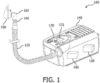
FIG. 1 , in one embodiment, is a representation of an examplenon-invasive ventilation system 100. In this embodiment, the system is a single limb ventilator such that there is a leak flow near the patient connection, and such that patient-exhaled gas has the potential to travel in a reverse direction through the blower during exhalation. The system includes acontroller 120, which can be a conventional microprocessor, an application specific integrated circuit (ASIC), a system on chip (SOC), and/or a field-programmable gate arrays (FPGA), among other types of controllers. A controller may be implemented with or without employing a processor, and also may be implemented as a combination of dedicated hardware to perform some functions and a processor (e.g., one or more programmed microprocessors and associated circuitry) to perform other functions. - The
controller 120 can be coupled with or otherwise in communication with any needed memory, power supply, I/O devices, control circuitry, and/or other devices necessary for operation of the system according to the embodiments described or otherwise envisioned herein. For example, in various implementations, a processor or controller may be associated with one or more storage media. In some implementations, the storage media may be encoded with one or more programs that, when executed on one or more processors and/or controllers, perform at least some of the functions discussed herein. Various storage media may be fixed within a processor or controller or may be transportable, such that the one or more programs stored thereon can be loaded into a processor or controller so as to implement various aspects of the present invention discussed herein. The terms "program" or "computer program" are used herein in a generic sense to refer to any type of computer code (e.g., software or microcode) that can be employed to program one or more processors or controllers. - According to an embodiment, the non-invasive ventilation system includes a tube or
tubing 130 that delivers gas from theremote ventilator component 140 to thepatient interface 150.Patient interface 150 can be, for example, a face mask that covers all or a portion of the patient's mouth and/or nose. There may be masks of many different sizes to accommodate patients or individuals of different sizes, and/or the mask may be adjustable. As another alternative,patient interface 150 may fit within or on, or otherwise interact with, a tracheostomy tube. Accordingly, thepatient interface 150 may be a variety of sizes to accommodate tracheostomies of different shapes and sizes. The patient interface is configured to fit with at least a portion of the patient's airway. -
Tubing 130 and/orpatient interface 150 can also include a CO2 sensor 160. InFIG. 1 , for example, the CO2 sensor 160 is located near theelbow 162 ofpatient interface 150 ortubing 130. According to an embodiment, the CO2 sensor 160 is in wired or wireless communication withcontroller 120. It should be noted that although CO2 sensor 160 is depicted as an integral CO2 sensor inFIG. 1 , the sensor may be separate from the ventilator, tubing, or mask. -
System 100 also includes ablower 180 with a motor, which generates flow and pressure for the system. The blower motor is controlled by a blower motor controller, which can control, for example, the speed of the motor. According to an embodiment, the blower motor is a component of the blower, which can include an impeller, housing, and motor. The flow and pressure of the system is determined in part by the speed of the blower motor, the activity of which in turn is controlled by the blower motor controller. The blower motor controller can be the same controller ascontroller 120, or can be a separate controller preferably in communication withcontroller 120. The controller can be any processor, and can be coupled with or otherwise in communication with any needed memory, power supply, I/O devices, control circuitry, and/or other devices necessary for operation of the system according to the embodiments described or otherwise envisioned herein. - According to an embodiment,
system 100 uses both ambient air and a high-pressure gas source, such as an oxygen source, to produce the gas delivered to the patient. The gas source can be any gas source that might be utilized, such as surrounding environmental air, an oxygen tank, a nitrogen tank, mixtures thereof, as well as a very wide variety of other gas sources. - According to an embodiment, the
non-invasive ventilation system 100 also includes a user interface (UI) 170.UI 170 includes graphical, textual and/or auditory information that the system presents to the user, such as a clinician, as well as the control sequences - such as keystrokes, computer mouse movements or selections, and/or touchscreen movements or selections, among other control sequences - that the user utilizes to control the system. In one embodiment, theUI 170 is a graphical user interface. For example, as shown inFIG. 1 ,UI 170 includes adisplay screen 172.Display screen 172 may include, for example, a touchscreen enabling the user to change one or more settings of thenon-invasive ventilation system 100, as well as a graphical output that displays breathing and ventilation information to the user. - For example, according to an embodiment,
user interface 170 includes an interface such as a button or switch that the user pushes, slides, switches, or otherwise activates in order to activate the CO2 measurement. As another example, the display screen can include a touchscreen CO2 measurement button or other input mechanism using touch, a stylus, or another selection mechanism. The user interface can also provide the user with options and variables for the CO2 measurement routine, including the selection of the inspiratory positive airway pressure (IPAP) and/or expiratory positive airway pressure (EPAP) level during CO2 measurement, as well as the time period or number of breaths over which the CO2 measurement will occur. - According to an embodiment,
user interface 170 andcontroller 120 operate cooperatively to configure the non-invasive ventilator to obtain a CO2 measurement. Theuser interface 170 can be in communication withcontroller 120 such that when the user configures the system by selecting one or more functions or options, thecontroller 120 stores the information and activates the CO2 measurement accordingly. For example, the user can select, viauser interface 170, an EPAP level of 1 cmH2O for a period of two breaths during a CO2 measurement that will be obtained immediately. Thecontroller 120 receives the user input from the user interface and activates the CO2 measurement. Alternatively, the user can select, viauser interface 170, an EPAP level of 0 cmH2O for a period of four breaths during a CO2 measurement which will be obtained every 10 minutes. Thecontroller 120 receives the user input from the user interface and activates a timing mechanism for the next CO2 measurement. The user may also utilize the user interface to direct the controller to activate a CO2 measurement if a selected condition is detected, such as a change in average breath rate. Accordingly, thecontroller 120 receives the information from theuser interface 170 and begins monitoring for the triggering condition for CO2 measurement. - Referring to
FIG. 2 , there is a flowchart of amethod 200 for measuring CO2 in a non-invasive ventilator system. Atstep 210, anon-invasive ventilation system 100 is provided. The system is any of the non-invasive ventilation systems described or otherwise envisioned herein, and can include, for example, acontroller 120, ablower 180,tubing 130,patient interface 150, and CO2 sensor 160, among other components. - At
step 220 of the method, the user activates a CO2 measurement from the patient. For example, a clinician may determine - after reviewing the patient's condition, lab results, or other information relevant to a CO2 measurement - that a CO2 measurement is needed immediately. As yet another example, the clinician may determine that a regular or periodic CO2 measurement is necessary, and thus will configure the system to obtain a CO2 measurement at regular or periodic intervals. The interval may be, for example, every 3 to 5 minutes, every hour, every few hours, or any other desired interval. The clinician may alternatively determine that a CO2 measurement is necessary if a certain condition is triggered, such as a change in patient-triggered breathing or some other trigger. - The clinician can activate a CO2 measurement using the
UI 170. The non-invasive ventilator system receives a signal, such as a signal from the UI, comprising an instruction to obtain a CO2 measurement from a patient. For example, the UI can include a button or switch that the user pushes, slides, switches, or otherwise activates in order to activate the CO2 measurement. As another example, the display screen can include a touchscreen CO2 measurement button or other input mechanism using touch, a stylus, or another selection mechanism. The button or touchscreen button activates a pre-programmed routine that lowers the EPAP to a predetermined level for a predetermined number of breaths before raising the EPAP back to normal levels. The UI allows the user to select one or both of an EPAP level and a number of breaths for the CO2 measurement. For example, the clinician can select a pre-programmed CO2 measurement program or setting that adjusts the EPAP level to one (1) cmH2O for a period of two (2) breaths by the patient. The maximum number of breaths for a CO2 measurement can be based on the low leak alarm setting of the non-invasive ventilator system, which can vary by platform. - The EPAP level is preferably set to a level equal to or greater than 0 cmH2O and lower than 4 cmH2O during expiration. In some systems or scenarios, a setting of one (1) cmH2O during expiration, for example, provides positive pressure that prevents a mask flap - such as the anti-asphyxiation valve - from opening during CO2 measurement. An open anti-asphyxiation valve would negatively affect the CO2 measurement as exhaled gas from the patient will escape through the open valve before reaching the CO2 sensor. In contrast, in some systems or scenarios a setting of three (3) cmH2O during expiration will push too much gas into the system and similarly negatively affect the CO2 measurement.
- At
step 230 of the method, thenon-invasive ventilation system 100 lowers the EPAP level for a period of one or more patient breaths. Thecontroller 120 receives input from the user activating a pre-programmed CO2 measurement routine and/or determining one or more settings of a CO2 measurement routine. The controller can for example, execute a program stored in memory to accomplish the lowered EPAP. Since most non-invasive ventilator systems utilize flow from ablower 180 to control inspiratory and expiratory pressures, thecontroller 120 can send a control signal to theblower 180 to control or adjust the EPAP. To ensure that the routine includes only the prescribed number of patient breaths, the system includes a counting mechanism to determine how many breaths are given to or taken by the patient. For example, thecontroller 120 may include a timer and/or counter that tracks the number of breaths, or may use one or more of a pressure or airflow sensing to sense a patient breath. - The
non-invasive ventilation system 100 can be configured to interrupt, disrupt, or otherwise adjust leak compensation in order to lower the EPAP level and obtain the CO2 measurement. Obtaining a CO2 measurement using the methods and systems described or otherwise envisioned herein may be especially important during periods of high leaks in the non-invasive ventilator system when a larger amount of gas is flowing from the ventilator to the patient in order to compensate for the large leak. This dilutes normal CO2 measurements, since almost no exhaled flow may reach the CO2 sensor, and thus increases the need for the CO2 measurement embodiments described herein. Accordingly, the non-invasive ventilation system may include an override to deactivate or pause the leak compensation and allow for proper CO2 measurements using the described embodiments. - At
step 240 of the method, one or more CO2 measurements are obtained.System 100 can include a standalone or integrated CO2 sensor such as CO2 sensor 160 is located near theelbow 162 ofpatient interface 150 ortubing 130 inFIG. 1 . Alternatively, the CO2 sensor can be a standalone sensor in wired or wireless communication withnon-invasive ventilator system 100. The system, such ascontroller 120, sends a signal to the CO2 sensor with instructions to obtain one or more CO2 measurements during the period of lowered EPAP levels. In the case of a wireless standalone CO2 sensor, thecontroller 120 may send a wireless signal to the standalone CO2 sensor. - At
step 250 of the method, thenon-invasive ventilation system 100 returns the EPAP to its original pressure. Thecontroller 120 determines that the lowered EPAP phase of the selected or pre-programmed CO2 measurement routine is complete and that the EPAP should be returned to normal levels. Accordingly, thecontroller 120 sends a control signal to theblower 180 to control or adjust the EPAP. - In an automated or pre-programmed CO2 measurement routine, the completion of the lowered EPAP phase or the return of the EPAP to normal levels can trigger a countdown to the next lowered EPAP phase. Accordingly,
controller 120 may include, for example, a timer and/or clock that determines when the next CO2 measurement is required. In other systems, CO2 measurements are only obtained in direct response to a user's selection or activation. - At
step 260 of the method, thenon-invasive ventilation system 100 provides the output of the CO2 measurement to the user. This output could be provided, for example, viaUI 170 anddisplay screen 172. The CO2 measurement can be presented as a percentage, a concentration, or any other measurement. - If the system is executing a pre-programmed CO2 measurement routine, the method can return to step 230 at the appropriate time. For example, the clock or timer of
controller 120, or another clock or timer of the system, can determine that a predetermined number of breaths or amount of time has expired, and that, according to the pre-programmed routine, a new CO2 measurement is necessary. Alternatively, the system can return to normal EPAP levels and await a user instruction to activate a CO2 measurement atstep 220. - Referring to
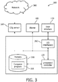
FIG. 3 , in one embodiment, is a block diagram of acomputer system 300, such as a computer system ofventilator system 100, in accordance with an embodiment. Thecomputer system 300 includes, for example, acontroller 120,memory 330, and I/O interface 350, among other possible components. -
Controller 120 can be a processor, an application specific integrated circuit (ASIC), a system on chip (SOC), and/or a field-programmable gate arrays (FPGA), among other types of controllers. The controller may be implemented with or without employing a processor, and also may be implemented as a combination of dedicated hardware to perform some functions and a processor (e.g., one or more programmed microprocessors and associated circuitry) to perform other functions. According to an embodiment, thecontroller 120 is coupled with or otherwise in communication with storage media such asmemory 330. In some implementations, the storage media may be encoded with one or more computer programs that, when executed on one or more processors and/or controllers, perform at least some of the functions discussed herein. Various storage media may be fixed within a processor or controller or may be transportable, such that the one or more programs stored thereon can be loaded into a processor or controller so as to implement various aspects of the present invention discussed herein. According to an embodiment,memory 330 may include one or morecomputer program products 335 configured to execute one or more embodiments of the CO2 measurement system. -
Computer system 300 communicates with one or more external devices, such as a CO2 sensor ormeasurement device 160,blower 180, and/oruser interface 170, all described herein. Communication with any one of these devices can be achieved via an input/output (I/O)interface 350. Communication can also or alternatively occur with any one of these devices via a direct wired connection, or via one ormore networks 360, for example, the Internet, a local area network, a wide area network, and/or a wireless network. For example, according to an embodiment the CO2 sensor ormeasurement device 160 is an external device, and thecomputer system 300 communicates vianetwork 360. Alternatively, the CO2 sensor or measurement device is an integrated component of the system and the computer system communicates via a direct connection. - Referring to
FIG. 3 , in one embodiment, is agraph 400 showing an exemplary non-invasiveventilator pressure curve 410 in cmH2O. The curve illustrates the pressure applied to the patient with risingportions 420 of the curve to create the prescribed inspiratory positive airway pressure (IPAP) to the patient's respiratory system during inhalation, and on fallingportions 430 of the curve when exhalation begins to create the prescribed expiratory positive airway pressure (EPAP) to the respiratory system during exhalation. As shown in the curve inFIG. 4 , the IPAP is approximately 10 cmH2O, and the EPAP is approximately 4 cmH2O. According to an embodiment, the pressure is controlled by controlling the blower as described herein. - According to an embodiment, at some time prior to time T1, the user activates the system to obtain a CO2 measurement from the patient. For example, the clinician may determine that a CO2 measurement is needed immediately, or may determine that a regular or periodic CO2 measurement is necessary, and thus will configure the system to obtain a CO2 measurement at regular or periodic intervals. At time T1, the
non-invasive ventilation system 100 lowers the IPAP and/or EPAP levels for a period of one or more patient breaths. According to an embodiment, thecontroller 120 applies a signal to theblower 180 to establish the lower prescribed IPAP pressure during inhalation and the lower prescribed EPAP pressure during exhalation. As shown in the curve inFIG. 4 , the lowered IPAP is approximately 7 cmH2O, and the lowered EPAP is approximately 1 cmH2O, for a period of two breaths during time T. - During time T, one or more CO2 measurements are obtained.
System 100 can include a standalone or integrated CO2 sensor such as CO2 sensor 160 is located near theelbow 162 ofpatient interface 150 ortubing 130 inFIG. 1 . Alternatively, the CO2 sensor can be a standalone sensor in wired or wireless communication withnon-invasive ventilator system 100. The system, such ascontroller 120, sends a signal to the CO2 sensor to obtain one or more CO2 measurements during the period of lowered EPAP levels. In the case of a wireless standalone CO2 sensor, thecontroller 120 may send a wireless signal to the standalone CO2 sensor. - At time T2, the
non-invasive ventilation system 100 raises the IPAP and EPAP levels to pre-measurement levels. As shown in the curve inFIG. 4 , the IPAP level is returned to approximately 10 cmH2O, and the EPAP is returned to approximately 4 cmH2O. According to an embodiment, thecontroller 120 determines that the lowered EPAP phase of the selected or pre-programmed CO2 measurement routine is complete and that the EPAP should be returned to normal levels. Accordingly, thecontroller 120 sends a signal to theblower 180 to control or adjust the EPAP. - The indefinite articles "a" and "an," as used herein in the specification and in the claims, unless clearly indicated to the contrary, should be understood to mean "at least one."
- The phrase "and/or," as used herein in the specification and in the claims, should be understood to mean "either or both" of the elements so conjoined, i.e., elements that are conjunctively present in some cases and disjunctively present in other cases. Multiple elements listed with "and/or" should be construed in the same fashion, i.e., "one or more" of the elements so conjoined. Other elements may optionally be present other than the elements specifically identified by the "and/or" clause, whether related or unrelated to those elements specifically identified.
- As used herein in the specification and in the claims, "or" should be understood to have the same meaning as "and/or" as defined above. For example, when separating items in a list, "or" or "and/or" shall be interpreted as being inclusive, i.e., the inclusion of at least one, but also including more than one, of a number or list of elements, and, optionally, additional unlisted items. Only terms clearly indicated to the contrary, such as "only one of' or "exactly one of," or, when used in the claims, "consisting of," will refer to the inclusion of exactly one element of a number or list of elements. In general, the term "or" as used herein shall only be interpreted as indicating exclusive alternatives (i.e. "one or the other but not both") when preceded by terms of exclusivity, such as "either," "one of," "only one of," or "exactly one of."
- As used herein in the specification and in the claims, the phrase "at least one," in reference to a list of one or more elements, should be understood to mean at least one element selected from any one or more of the elements in the list of elements, but not necessarily including at least one of each and every element specifically listed within the list of elements and not excluding any combinations of elements in the list of elements. This definition also allows that elements may optionally be present other than the elements specifically identified within the list of elements to which the phrase "at least one" refers, whether related or unrelated to those elements specifically identified.
- In the claims, as well as in the specification above, all transitional phrases such as "comprising," "including," "carrying," "having," "containing," "involving," "holding," "composed of," and the like are to be understood to be open-ended, i.e., to mean including but not limited to. Only the transitional phrases "consisting of' and "consisting essentially of' shall be closed or semi-closed transitional phrases, respectively.
Claims (10)
- A controller (120) of a non-invasive ventilator system (100) configured to measure a patient's expired CO2 level while maintaining a positive inspiratory pressure, the controller configured to:receive, from a user interface (170) of the non-invasive ventilator system, a signal comprising an instruction to obtain a CO2 measurement from a patient;lower, in response to the signal for a first time period comprising one or more breaths, (i) the expiratory positive airway pressure of the non-invasive ventilator system from a first, higher level to a second, lower level, and (ii) the inspiratory positive airway pressure of the non-invasive ventilator system from a third, higher level to a fourth lower level;send a signal to a CO2 sensor (160) of the non-invasive ventilator system, the signal comprising instructions to obtain the CO2 measurement during the first time period; andreturn, after the first time period, the expiratory positive airway pressure to the first, higher level and the inspiratory positive airway pressure to the third, higher level.
- The controller of claim 1, wherein the controller is configured to lower the expiratory positive airway pressure from a first, higher level to a second, lower level by sending a control signal to a blower (180) of the non-invasive ventilator system.
- The controller of claim 1, wherein the second, lower level is approximately 1 cmH20.
- The controller of claim 1, wherein the first time period is approximately two breaths.
- The controller of claim 1, wherein the controller is further configured to provide the CO2 measurement to a user via a display screen (172) configured to display the obtained CO2 measurement.
- A non-invasive ventilator (100) configured to measure a patient's expired CO2 level while maintaining a positive inspiratory pressure, the non-invasive ventilator comprising:a user interface (170),a CO2 sensor (160), andthe controller (120) of claim 1.
- The non-invasive ventilator of claim 6, wherein the controller is configured to lower the expiratory positive airway pressure by controlling the activity of a blower (180) of the non-invasive ventilator.
- The non-invasive ventilator of claim 6, wherein the CO2 sensor is an integrated sensor located near a patient interface (150).
- The non-invasive ventilator of claim 6, further comprising a display screen (172) configured to display the obtained CO2 measurement.
- The non-invasive ventilator of claim 6, wherein the user interface is a button.
Applications Claiming Priority (2)
| Application Number | Priority Date | Filing Date | Title |
|---|---|---|---|
| US201562261924P | 2015-12-02 | 2015-12-02 | |
| PCT/IB2016/057086 WO2017093862A1 (en) | 2015-12-02 | 2016-11-24 | Method of co2 measurement during non-invasive ventilation |
Publications (2)
| Publication Number | Publication Date |
|---|---|
| EP3383464A1 EP3383464A1 (en) | 2018-10-10 |
| EP3383464B1 true EP3383464B1 (en) | 2020-10-28 |
Family
ID=57471945
Family Applications (1)
| Application Number | Title | Priority Date | Filing Date |
|---|---|---|---|
| EP16805524.2A Active EP3383464B1 (en) | 2015-12-02 | 2016-11-24 | Method of co2 measurement during non-invasive ventilation |
Country Status (6)
| Country | Link |
|---|---|
| US (1) | US10869978B2 (en) |
| EP (1) | EP3383464B1 (en) |
| JP (1) | JP6980657B2 (en) |
| CN (1) | CN108472465B (en) |
| RU (1) | RU2732449C2 (en) |
| WO (1) | WO2017093862A1 (en) |
Families Citing this family (4)
| Publication number | Priority date | Publication date | Assignee | Title |
|---|---|---|---|---|
| CN108939231B (en) * | 2018-06-06 | 2020-05-22 | 山东大学 | Has CO2Remote management noninvasive ventilator with monitoring function and working method thereof |
| US20230338691A1 (en) * | 2020-06-30 | 2023-10-26 | ResMed Asia Pte. Ltd. | A patient interface and a positioning and stabilising structure for a patient interface |
| USD989290S1 (en) * | 2020-12-31 | 2023-06-13 | Corvent Medical, Inc. | Ventilator tubing assembly |
| USD989291S1 (en) * | 2020-12-31 | 2023-06-13 | Corvent Medical, Inc. | Ventilator tubing assembly |
Family Cites Families (22)
| Publication number | Priority date | Publication date | Assignee | Title |
|---|---|---|---|---|
| US6371113B1 (en) | 1996-10-10 | 2002-04-16 | Datex-Ohmeda, Inc. | Zero flow pause during volume ventilation |
| US6099481A (en) * | 1997-11-03 | 2000-08-08 | Ntc Technology, Inc. | Respiratory profile parameter determination method and apparatus |
| US6990980B2 (en) * | 2000-09-28 | 2006-01-31 | Invacare Corporation | Carbon dioxide-based Bi-level CPAP control |
| US6981947B2 (en) * | 2002-01-22 | 2006-01-03 | University Of Florida Research Foundation, Inc. | Method and apparatus for monitoring respiratory gases during anesthesia |
| DE10139881B4 (en) * | 2001-08-20 | 2017-06-08 | Resmed R&D Germany Gmbh | Apparatus for supplying a breathing gas and method for controlling the same |
| US7938114B2 (en) * | 2001-10-12 | 2011-05-10 | Ric Investments Llc | Auto-titration bi-level pressure support system and method of using same |
| US7886740B2 (en) * | 2003-01-28 | 2011-02-15 | Beth Israel Deaconess Medical Center, Inc. | Gas systems and methods for enabling respiratory stability |
| AU2008323625A1 (en) * | 2007-11-16 | 2009-05-22 | Philip John Peyton | System and method for monitoring cardiac output |
| AT507187B1 (en) * | 2008-10-23 | 2010-03-15 | Helmut Dr Buchberger | INHALER |
| US9567047B2 (en) * | 2009-08-24 | 2017-02-14 | Kevin Gurr | Rebreather control parameter system and dive resource management system |
| JP5795590B2 (en) * | 2009-11-03 | 2015-10-14 | コーニンクレッカ フィリップス エヌ ヴェ | System and method for monitoring respiration |
| BR112012013548B1 (en) * | 2009-12-07 | 2020-03-24 | Koninklijke Philips N.V. | PRESSURE SUPPORT SYSTEM |
| JP5858927B2 (en) * | 2009-12-28 | 2016-02-10 | ユニバーシティ オブ フロリダ リサーチ ファンデーション インコーポレーティッド | A system for evaluating real-time lung mechanics |
| WO2011080701A1 (en) * | 2009-12-29 | 2011-07-07 | Koninklijke Philips Electronics N.V. | System and method for detecting valid breaths from a capnometry signal |
| RU2013133854A (en) * | 2010-12-21 | 2015-01-27 | Конинклейке Филипс Электроникс Н.В. | SYSTEM AND METHOD FOR DETERMINING CARBON DIOXIDE DISTRIBUTED IN THE PROCESS OF NON-INVASIVE LUNG VENTILATION |
| US20120272962A1 (en) * | 2011-04-29 | 2012-11-01 | Nellcor Puritan Bennett Llc | Methods and systems for managing a ventilator patient with a capnometer |
| US20130053717A1 (en) * | 2011-08-30 | 2013-02-28 | Nellcor Puritan Bennett Llc | Automatic ventilator challenge to induce spontaneous breathing efforts |
| US8985107B2 (en) | 2012-02-28 | 2015-03-24 | General Electric Company | Method, arrangement and computer program product for respiratory gas monitoring of ventilated patients |
| DE102012024672A1 (en) * | 2012-12-18 | 2014-06-18 | Dräger Medical GmbH | Respirator and method of operating a ventilator |
| WO2015048766A1 (en) * | 2013-09-30 | 2015-04-02 | The Arizona Board Of Regents On Behalf Of The University Of Arizona | A home-based heliox system with carbon dioxide removal |
| US10532174B2 (en) * | 2014-02-21 | 2020-01-14 | Masimo Corporation | Assistive capnography device |
| CN204671691U (en) * | 2015-05-22 | 2015-09-30 | 刁玉刚 | A kind of oropharyngeal airway with respiration monitoring function |
-
2016
- 2016-11-24 EP EP16805524.2A patent/EP3383464B1/en active Active
- 2016-11-24 JP JP2018528008A patent/JP6980657B2/en active Active
- 2016-11-24 WO PCT/IB2016/057086 patent/WO2017093862A1/en active Application Filing
- 2016-11-24 US US15/780,432 patent/US10869978B2/en active Active
- 2016-11-24 CN CN201680077527.1A patent/CN108472465B/en active Active
- 2016-11-24 RU RU2018123996A patent/RU2732449C2/en active
Non-Patent Citations (1)
| Title |
|---|
| None * |
Also Published As
| Publication number | Publication date |
|---|---|
| WO2017093862A1 (en) | 2017-06-08 |
| JP2019500933A (en) | 2019-01-17 |
| US10869978B2 (en) | 2020-12-22 |
| CN108472465B (en) | 2021-08-31 |
| RU2018123996A3 (en) | 2020-04-14 |
| RU2018123996A (en) | 2020-01-09 |
| CN108472465A (en) | 2018-08-31 |
| EP3383464A1 (en) | 2018-10-10 |
| JP6980657B2 (en) | 2021-12-15 |
| US20180361091A1 (en) | 2018-12-20 |
| RU2732449C2 (en) | 2020-09-17 |
Similar Documents
| Publication | Publication Date | Title |
|---|---|---|
| US20190374733A1 (en) | Automatic peep selection for mechanical ventilation | |
| JP6200425B2 (en) | Automatic patient synchronization for noninvasive ventilation | |
| JP6223340B2 (en) | Method and apparatus for controlling a ventilator device | |
| EP2509668B1 (en) | System for providing support therapy while determining concentrations of a molecular gaseous expired by a subject receiving pressure support therapy | |
| JP6165632B2 (en) | System and method for providing forced inspiration-expiration to a subject | |
| JP6173320B2 (en) | Non-invasive ventilation measurement | |
| EP3383464B1 (en) | Method of co2 measurement during non-invasive ventilation | |
| US10758157B2 (en) | Determining if airway clearance is required during respiratory therapy | |
| US20150040903A1 (en) | Starting pressure for respiratory therapy devices | |
| US9642976B2 (en) | Systems and methods for intra-pulmonary percussive ventilation integrated in a ventilator | |
| JP2014506163A5 (en) | ||
| US20160325061A1 (en) | Patient ventilator asynchrony detection | |
| US20140326242A1 (en) | Sysems and methods for using partial co2 rebreathing integrated in a ventilator and measurements thereof to determine noninvasive cardiac output | |
| US9950132B2 (en) | Systems and methods to determine the fraction of inhaled oxygen during ventilation | |
| US11291786B2 (en) | Reducing hypercapnic respiratory failure during mechanical ventilation | |
| JP2015519119A5 (en) | ||
| US10881821B2 (en) | Mechanical ventilation based on alveolar ventilation |
Legal Events
| Date | Code | Title | Description |
|---|---|---|---|
| STAA | Information on the status of an ep patent application or granted ep patent |
Free format text: STATUS: UNKNOWN |
|
| STAA | Information on the status of an ep patent application or granted ep patent |
Free format text: STATUS: THE INTERNATIONAL PUBLICATION HAS BEEN MADE |
|
| PUAI | Public reference made under article 153(3) epc to a published international application that has entered the european phase |
Free format text: ORIGINAL CODE: 0009012 |
|
| STAA | Information on the status of an ep patent application or granted ep patent |
Free format text: STATUS: REQUEST FOR EXAMINATION WAS MADE |
|
| 17P | Request for examination filed |
Effective date: 20180702 |
|
| AK | Designated contracting states |
Kind code of ref document: A1 Designated state(s): AL AT BE BG CH CY CZ DE DK EE ES FI FR GB GR HR HU IE IS IT LI LT LU LV MC MK MT NL NO PL PT RO RS SE SI SK SM TR |
|
| AX | Request for extension of the european patent |
Extension state: BA ME |
|
| DAV | Request for validation of the european patent (deleted) | ||
| DAX | Request for extension of the european patent (deleted) | ||
| RAP1 | Party data changed (applicant data changed or rights of an application transferred) |
Owner name: KONINKLIJKE PHILIPS N.V. |
|
| GRAP | Despatch of communication of intention to grant a patent |
Free format text: ORIGINAL CODE: EPIDOSNIGR1 |
|
| STAA | Information on the status of an ep patent application or granted ep patent |
Free format text: STATUS: GRANT OF PATENT IS INTENDED |
|
| INTG | Intention to grant announced |
Effective date: 20200529 |
|
| GRAS | Grant fee paid |
Free format text: ORIGINAL CODE: EPIDOSNIGR3 |
|
| GRAA | (expected) grant |
Free format text: ORIGINAL CODE: 0009210 |
|
| STAA | Information on the status of an ep patent application or granted ep patent |
Free format text: STATUS: THE PATENT HAS BEEN GRANTED |
|
| AK | Designated contracting states |
Kind code of ref document: B1 Designated state(s): AL AT BE BG CH CY CZ DE DK EE ES FI FR GB GR HR HU IE IS IT LI LT LU LV MC MK MT NL NO PL PT RO RS SE SI SK SM TR |
|
| REG | Reference to a national code |
Ref country code: GB Ref legal event code: FG4D |
|
| REG | Reference to a national code |
Ref country code: CH Ref legal event code: EP |
|
| REG | Reference to a national code |
Ref country code: AT Ref legal event code: REF Ref document number: 1327585 Country of ref document: AT Kind code of ref document: T Effective date: 20201115 |
|
| REG | Reference to a national code |
Ref country code: DE Ref legal event code: R096 Ref document number: 602016046801 Country of ref document: DE |
|
| REG | Reference to a national code |
Ref country code: IE Ref legal event code: FG4D |
|
| REG | Reference to a national code |
Ref country code: AT Ref legal event code: MK05 Ref document number: 1327585 Country of ref document: AT Kind code of ref document: T Effective date: 20201028 |
|
| REG | Reference to a national code |
Ref country code: NL Ref legal event code: MP Effective date: 20201028 |
|
| PG25 | Lapsed in a contracting state [announced via postgrant information from national office to epo] |
Ref country code: NO Free format text: LAPSE BECAUSE OF FAILURE TO SUBMIT A TRANSLATION OF THE DESCRIPTION OR TO PAY THE FEE WITHIN THE PRESCRIBED TIME-LIMIT Effective date: 20210128 Ref country code: RS Free format text: LAPSE BECAUSE OF FAILURE TO SUBMIT A TRANSLATION OF THE DESCRIPTION OR TO PAY THE FEE WITHIN THE PRESCRIBED TIME-LIMIT Effective date: 20201028 Ref country code: PT Free format text: LAPSE BECAUSE OF FAILURE TO SUBMIT A TRANSLATION OF THE DESCRIPTION OR TO PAY THE FEE WITHIN THE PRESCRIBED TIME-LIMIT Effective date: 20210301 Ref country code: GR Free format text: LAPSE BECAUSE OF FAILURE TO SUBMIT A TRANSLATION OF THE DESCRIPTION OR TO PAY THE FEE WITHIN THE PRESCRIBED TIME-LIMIT Effective date: 20210129 Ref country code: FI Free format text: LAPSE BECAUSE OF FAILURE TO SUBMIT A TRANSLATION OF THE DESCRIPTION OR TO PAY THE FEE WITHIN THE PRESCRIBED TIME-LIMIT Effective date: 20201028 |
|
| REG | Reference to a national code |
Ref country code: LT Ref legal event code: MG4D |
|
| PG25 | Lapsed in a contracting state [announced via postgrant information from national office to epo] |
Ref country code: SE Free format text: LAPSE BECAUSE OF FAILURE TO SUBMIT A TRANSLATION OF THE DESCRIPTION OR TO PAY THE FEE WITHIN THE PRESCRIBED TIME-LIMIT Effective date: 20201028 Ref country code: BG Free format text: LAPSE BECAUSE OF FAILURE TO SUBMIT A TRANSLATION OF THE DESCRIPTION OR TO PAY THE FEE WITHIN THE PRESCRIBED TIME-LIMIT Effective date: 20210128 Ref country code: LV Free format text: LAPSE BECAUSE OF FAILURE TO SUBMIT A TRANSLATION OF THE DESCRIPTION OR TO PAY THE FEE WITHIN THE PRESCRIBED TIME-LIMIT Effective date: 20201028 Ref country code: PL Free format text: LAPSE BECAUSE OF FAILURE TO SUBMIT A TRANSLATION OF THE DESCRIPTION OR TO PAY THE FEE WITHIN THE PRESCRIBED TIME-LIMIT Effective date: 20201028 Ref country code: IS Free format text: LAPSE BECAUSE OF FAILURE TO SUBMIT A TRANSLATION OF THE DESCRIPTION OR TO PAY THE FEE WITHIN THE PRESCRIBED TIME-LIMIT Effective date: 20210228 Ref country code: AT Free format text: LAPSE BECAUSE OF FAILURE TO SUBMIT A TRANSLATION OF THE DESCRIPTION OR TO PAY THE FEE WITHIN THE PRESCRIBED TIME-LIMIT Effective date: 20201028 Ref country code: ES Free format text: LAPSE BECAUSE OF FAILURE TO SUBMIT A TRANSLATION OF THE DESCRIPTION OR TO PAY THE FEE WITHIN THE PRESCRIBED TIME-LIMIT Effective date: 20201028 |
|
| PG25 | Lapsed in a contracting state [announced via postgrant information from national office to epo] |
Ref country code: HR Free format text: LAPSE BECAUSE OF FAILURE TO SUBMIT A TRANSLATION OF THE DESCRIPTION OR TO PAY THE FEE WITHIN THE PRESCRIBED TIME-LIMIT Effective date: 20201028 Ref country code: NL Free format text: LAPSE BECAUSE OF FAILURE TO SUBMIT A TRANSLATION OF THE DESCRIPTION OR TO PAY THE FEE WITHIN THE PRESCRIBED TIME-LIMIT Effective date: 20201028 |
|
| REG | Reference to a national code |
Ref country code: CH Ref legal event code: PL |
|
| REG | Reference to a national code |
Ref country code: DE Ref legal event code: R097 Ref document number: 602016046801 Country of ref document: DE |
|
| PG25 | Lapsed in a contracting state [announced via postgrant information from national office to epo] |
Ref country code: RO Free format text: LAPSE BECAUSE OF FAILURE TO SUBMIT A TRANSLATION OF THE DESCRIPTION OR TO PAY THE FEE WITHIN THE PRESCRIBED TIME-LIMIT Effective date: 20201028 Ref country code: SK Free format text: LAPSE BECAUSE OF FAILURE TO SUBMIT A TRANSLATION OF THE DESCRIPTION OR TO PAY THE FEE WITHIN THE PRESCRIBED TIME-LIMIT Effective date: 20201028 Ref country code: EE Free format text: LAPSE BECAUSE OF FAILURE TO SUBMIT A TRANSLATION OF THE DESCRIPTION OR TO PAY THE FEE WITHIN THE PRESCRIBED TIME-LIMIT Effective date: 20201028 Ref country code: CZ Free format text: LAPSE BECAUSE OF FAILURE TO SUBMIT A TRANSLATION OF THE DESCRIPTION OR TO PAY THE FEE WITHIN THE PRESCRIBED TIME-LIMIT Effective date: 20201028 Ref country code: SM Free format text: LAPSE BECAUSE OF FAILURE TO SUBMIT A TRANSLATION OF THE DESCRIPTION OR TO PAY THE FEE WITHIN THE PRESCRIBED TIME-LIMIT Effective date: 20201028 Ref country code: LT Free format text: LAPSE BECAUSE OF FAILURE TO SUBMIT A TRANSLATION OF THE DESCRIPTION OR TO PAY THE FEE WITHIN THE PRESCRIBED TIME-LIMIT Effective date: 20201028 Ref country code: LU Free format text: LAPSE BECAUSE OF NON-PAYMENT OF DUE FEES Effective date: 20201124 Ref country code: MC Free format text: LAPSE BECAUSE OF FAILURE TO SUBMIT A TRANSLATION OF THE DESCRIPTION OR TO PAY THE FEE WITHIN THE PRESCRIBED TIME-LIMIT Effective date: 20201028 |
|
| REG | Reference to a national code |
Ref country code: BE Ref legal event code: MM Effective date: 20201130 |
|
| PG25 | Lapsed in a contracting state [announced via postgrant information from national office to epo] |
Ref country code: LI Free format text: LAPSE BECAUSE OF NON-PAYMENT OF DUE FEES Effective date: 20201130 Ref country code: CH Free format text: LAPSE BECAUSE OF NON-PAYMENT OF DUE FEES Effective date: 20201130 Ref country code: DK Free format text: LAPSE BECAUSE OF FAILURE TO SUBMIT A TRANSLATION OF THE DESCRIPTION OR TO PAY THE FEE WITHIN THE PRESCRIBED TIME-LIMIT Effective date: 20201028 |
|
| PLBE | No opposition filed within time limit |
Free format text: ORIGINAL CODE: 0009261 |
|
| STAA | Information on the status of an ep patent application or granted ep patent |
Free format text: STATUS: NO OPPOSITION FILED WITHIN TIME LIMIT |
|
| GBPC | Gb: european patent ceased through non-payment of renewal fee |
Effective date: 20210128 |
|
| 26N | No opposition filed |
Effective date: 20210729 |
|
| PG25 | Lapsed in a contracting state [announced via postgrant information from national office to epo] |
Ref country code: FR Free format text: LAPSE BECAUSE OF NON-PAYMENT OF DUE FEES Effective date: 20201228 Ref country code: AL Free format text: LAPSE BECAUSE OF FAILURE TO SUBMIT A TRANSLATION OF THE DESCRIPTION OR TO PAY THE FEE WITHIN THE PRESCRIBED TIME-LIMIT Effective date: 20201028 Ref country code: IE Free format text: LAPSE BECAUSE OF NON-PAYMENT OF DUE FEES Effective date: 20201124 Ref country code: IT Free format text: LAPSE BECAUSE OF FAILURE TO SUBMIT A TRANSLATION OF THE DESCRIPTION OR TO PAY THE FEE WITHIN THE PRESCRIBED TIME-LIMIT Effective date: 20201028 |
|
| PG25 | Lapsed in a contracting state [announced via postgrant information from national office to epo] |
Ref country code: SI Free format text: LAPSE BECAUSE OF FAILURE TO SUBMIT A TRANSLATION OF THE DESCRIPTION OR TO PAY THE FEE WITHIN THE PRESCRIBED TIME-LIMIT Effective date: 20201028 Ref country code: GB Free format text: LAPSE BECAUSE OF NON-PAYMENT OF DUE FEES Effective date: 20210128 |
|
| PG25 | Lapsed in a contracting state [announced via postgrant information from national office to epo] |
Ref country code: IS Free format text: LAPSE BECAUSE OF FAILURE TO SUBMIT A TRANSLATION OF THE DESCRIPTION OR TO PAY THE FEE WITHIN THE PRESCRIBED TIME-LIMIT Effective date: 20210228 Ref country code: TR Free format text: LAPSE BECAUSE OF FAILURE TO SUBMIT A TRANSLATION OF THE DESCRIPTION OR TO PAY THE FEE WITHIN THE PRESCRIBED TIME-LIMIT Effective date: 20201028 Ref country code: MT Free format text: LAPSE BECAUSE OF FAILURE TO SUBMIT A TRANSLATION OF THE DESCRIPTION OR TO PAY THE FEE WITHIN THE PRESCRIBED TIME-LIMIT Effective date: 20201028 Ref country code: CY Free format text: LAPSE BECAUSE OF FAILURE TO SUBMIT A TRANSLATION OF THE DESCRIPTION OR TO PAY THE FEE WITHIN THE PRESCRIBED TIME-LIMIT Effective date: 20201028 |
|
| PG25 | Lapsed in a contracting state [announced via postgrant information from national office to epo] |
Ref country code: MK Free format text: LAPSE BECAUSE OF FAILURE TO SUBMIT A TRANSLATION OF THE DESCRIPTION OR TO PAY THE FEE WITHIN THE PRESCRIBED TIME-LIMIT Effective date: 20201028 |
|
| PG25 | Lapsed in a contracting state [announced via postgrant information from national office to epo] |
Ref country code: BE Free format text: LAPSE BECAUSE OF NON-PAYMENT OF DUE FEES Effective date: 20201130 |
|
| PGFP | Annual fee paid to national office [announced via postgrant information from national office to epo] |
Ref country code: DE Payment date: 20231127 Year of fee payment: 8 |