EP3381393A1 - An ablation probe - Google Patents
An ablation probe Download PDFInfo
- Publication number
- EP3381393A1 EP3381393A1 EP17164403.2A EP17164403A EP3381393A1 EP 3381393 A1 EP3381393 A1 EP 3381393A1 EP 17164403 A EP17164403 A EP 17164403A EP 3381393 A1 EP3381393 A1 EP 3381393A1
- Authority
- EP
- European Patent Office
- Prior art keywords
- coolant
- ablation probe
- applicator
- deformable member
- feeding cable
- Prior art date
- Legal status (The legal status is an assumption and is not a legal conclusion. Google has not performed a legal analysis and makes no representation as to the accuracy of the status listed.)
- Withdrawn
Links
Images


Classifications
-
- A—HUMAN NECESSITIES
- A61—MEDICAL OR VETERINARY SCIENCE; HYGIENE
- A61B—DIAGNOSIS; SURGERY; IDENTIFICATION
- A61B18/00—Surgical instruments, devices or methods for transferring non-mechanical forms of energy to or from the body
- A61B18/04—Surgical instruments, devices or methods for transferring non-mechanical forms of energy to or from the body by heating
- A61B18/12—Surgical instruments, devices or methods for transferring non-mechanical forms of energy to or from the body by heating by passing a current through the tissue to be heated, e.g. high-frequency current
- A61B18/14—Probes or electrodes therefor
- A61B18/1477—Needle-like probes
-
- A—HUMAN NECESSITIES
- A61—MEDICAL OR VETERINARY SCIENCE; HYGIENE
- A61B—DIAGNOSIS; SURGERY; IDENTIFICATION
- A61B1/00—Instruments for performing medical examinations of the interior of cavities or tubes of the body by visual or photographical inspection, e.g. endoscopes; Illuminating arrangements therefor
- A61B1/00064—Constructional details of the endoscope body
- A61B1/00071—Insertion part of the endoscope body
- A61B1/0008—Insertion part of the endoscope body characterised by distal tip features
- A61B1/00087—Tools
-
- A—HUMAN NECESSITIES
- A61—MEDICAL OR VETERINARY SCIENCE; HYGIENE
- A61B—DIAGNOSIS; SURGERY; IDENTIFICATION
- A61B1/00—Instruments for performing medical examinations of the interior of cavities or tubes of the body by visual or photographical inspection, e.g. endoscopes; Illuminating arrangements therefor
- A61B1/012—Instruments for performing medical examinations of the interior of cavities or tubes of the body by visual or photographical inspection, e.g. endoscopes; Illuminating arrangements therefor characterised by internal passages or accessories therefor
- A61B1/018—Instruments for performing medical examinations of the interior of cavities or tubes of the body by visual or photographical inspection, e.g. endoscopes; Illuminating arrangements therefor characterised by internal passages or accessories therefor for receiving instruments
-
- A—HUMAN NECESSITIES
- A61—MEDICAL OR VETERINARY SCIENCE; HYGIENE
- A61B—DIAGNOSIS; SURGERY; IDENTIFICATION
- A61B1/00—Instruments for performing medical examinations of the interior of cavities or tubes of the body by visual or photographical inspection, e.g. endoscopes; Illuminating arrangements therefor
- A61B1/267—Instruments for performing medical examinations of the interior of cavities or tubes of the body by visual or photographical inspection, e.g. endoscopes; Illuminating arrangements therefor for the respiratory tract, e.g. laryngoscopes, bronchoscopes
- A61B1/2676—Bronchoscopes
-
- A—HUMAN NECESSITIES
- A61—MEDICAL OR VETERINARY SCIENCE; HYGIENE
- A61B—DIAGNOSIS; SURGERY; IDENTIFICATION
- A61B18/00—Surgical instruments, devices or methods for transferring non-mechanical forms of energy to or from the body
- A61B18/04—Surgical instruments, devices or methods for transferring non-mechanical forms of energy to or from the body by heating
- A61B18/12—Surgical instruments, devices or methods for transferring non-mechanical forms of energy to or from the body by heating by passing a current through the tissue to be heated, e.g. high-frequency current
- A61B18/14—Probes or electrodes therefor
- A61B18/1492—Probes or electrodes therefor having a flexible, catheter-like structure, e.g. for heart ablation
-
- A—HUMAN NECESSITIES
- A61—MEDICAL OR VETERINARY SCIENCE; HYGIENE
- A61B—DIAGNOSIS; SURGERY; IDENTIFICATION
- A61B18/00—Surgical instruments, devices or methods for transferring non-mechanical forms of energy to or from the body
- A61B18/18—Surgical instruments, devices or methods for transferring non-mechanical forms of energy to or from the body by applying electromagnetic radiation, e.g. microwaves
- A61B18/1815—Surgical instruments, devices or methods for transferring non-mechanical forms of energy to or from the body by applying electromagnetic radiation, e.g. microwaves using microwaves
-
- A—HUMAN NECESSITIES
- A61—MEDICAL OR VETERINARY SCIENCE; HYGIENE
- A61B—DIAGNOSIS; SURGERY; IDENTIFICATION
- A61B17/00—Surgical instruments, devices or methods, e.g. tourniquets
- A61B2017/00477—Coupling
-
- A—HUMAN NECESSITIES
- A61—MEDICAL OR VETERINARY SCIENCE; HYGIENE
- A61B—DIAGNOSIS; SURGERY; IDENTIFICATION
- A61B17/00—Surgical instruments, devices or methods, e.g. tourniquets
- A61B2017/00831—Material properties
- A61B2017/00862—Material properties elastic or resilient
-
- A—HUMAN NECESSITIES
- A61—MEDICAL OR VETERINARY SCIENCE; HYGIENE
- A61B—DIAGNOSIS; SURGERY; IDENTIFICATION
- A61B17/00—Surgical instruments, devices or methods, e.g. tourniquets
- A61B2017/00831—Material properties
- A61B2017/00867—Material properties shape memory effect
-
- A—HUMAN NECESSITIES
- A61—MEDICAL OR VETERINARY SCIENCE; HYGIENE
- A61B—DIAGNOSIS; SURGERY; IDENTIFICATION
- A61B18/00—Surgical instruments, devices or methods for transferring non-mechanical forms of energy to or from the body
- A61B2018/00005—Cooling or heating of the probe or tissue immediately surrounding the probe
- A61B2018/00011—Cooling or heating of the probe or tissue immediately surrounding the probe with fluids
- A61B2018/00023—Cooling or heating of the probe or tissue immediately surrounding the probe with fluids closed, i.e. without wound contact by the fluid
-
- A—HUMAN NECESSITIES
- A61—MEDICAL OR VETERINARY SCIENCE; HYGIENE
- A61B—DIAGNOSIS; SURGERY; IDENTIFICATION
- A61B18/00—Surgical instruments, devices or methods for transferring non-mechanical forms of energy to or from the body
- A61B2018/00053—Mechanical features of the instrument of device
- A61B2018/00059—Material properties
- A61B2018/00071—Electrical conductivity
- A61B2018/00077—Electrical conductivity high, i.e. electrically conducting
-
- A—HUMAN NECESSITIES
- A61—MEDICAL OR VETERINARY SCIENCE; HYGIENE
- A61B—DIAGNOSIS; SURGERY; IDENTIFICATION
- A61B18/00—Surgical instruments, devices or methods for transferring non-mechanical forms of energy to or from the body
- A61B2018/00053—Mechanical features of the instrument of device
- A61B2018/00059—Material properties
- A61B2018/00071—Electrical conductivity
- A61B2018/00083—Electrical conductivity low, i.e. electrically insulating
-
- A—HUMAN NECESSITIES
- A61—MEDICAL OR VETERINARY SCIENCE; HYGIENE
- A61B—DIAGNOSIS; SURGERY; IDENTIFICATION
- A61B18/00—Surgical instruments, devices or methods for transferring non-mechanical forms of energy to or from the body
- A61B2018/00053—Mechanical features of the instrument of device
- A61B2018/00273—Anchoring means for temporary attachment of a device to tissue
- A61B2018/00279—Anchoring means for temporary attachment of a device to tissue deployable
- A61B2018/00285—Balloons
-
- A—HUMAN NECESSITIES
- A61—MEDICAL OR VETERINARY SCIENCE; HYGIENE
- A61B—DIAGNOSIS; SURGERY; IDENTIFICATION
- A61B18/00—Surgical instruments, devices or methods for transferring non-mechanical forms of energy to or from the body
- A61B2018/00571—Surgical instruments, devices or methods for transferring non-mechanical forms of energy to or from the body for achieving a particular surgical effect
- A61B2018/00577—Ablation
-
- A—HUMAN NECESSITIES
- A61—MEDICAL OR VETERINARY SCIENCE; HYGIENE
- A61B—DIAGNOSIS; SURGERY; IDENTIFICATION
- A61B18/00—Surgical instruments, devices or methods for transferring non-mechanical forms of energy to or from the body
- A61B2018/00636—Sensing and controlling the application of energy
- A61B2018/00773—Sensed parameters
- A61B2018/00791—Temperature
-
- A—HUMAN NECESSITIES
- A61—MEDICAL OR VETERINARY SCIENCE; HYGIENE
- A61B—DIAGNOSIS; SURGERY; IDENTIFICATION
- A61B18/00—Surgical instruments, devices or methods for transferring non-mechanical forms of energy to or from the body
- A61B2018/00636—Sensing and controlling the application of energy
- A61B2018/00773—Sensed parameters
- A61B2018/00875—Resistance or impedance
-
- A—HUMAN NECESSITIES
- A61—MEDICAL OR VETERINARY SCIENCE; HYGIENE
- A61B—DIAGNOSIS; SURGERY; IDENTIFICATION
- A61B18/00—Surgical instruments, devices or methods for transferring non-mechanical forms of energy to or from the body
- A61B2018/00982—Surgical instruments, devices or methods for transferring non-mechanical forms of energy to or from the body combined with or comprising means for visual or photographic inspections inside the body, e.g. endoscopes
-
- A—HUMAN NECESSITIES
- A61—MEDICAL OR VETERINARY SCIENCE; HYGIENE
- A61B—DIAGNOSIS; SURGERY; IDENTIFICATION
- A61B18/00—Surgical instruments, devices or methods for transferring non-mechanical forms of energy to or from the body
- A61B18/18—Surgical instruments, devices or methods for transferring non-mechanical forms of energy to or from the body by applying electromagnetic radiation, e.g. microwaves
- A61B18/1815—Surgical instruments, devices or methods for transferring non-mechanical forms of energy to or from the body by applying electromagnetic radiation, e.g. microwaves using microwaves
- A61B2018/1861—Surgical instruments, devices or methods for transferring non-mechanical forms of energy to or from the body by applying electromagnetic radiation, e.g. microwaves using microwaves with an instrument inserted into a body lumen or cavity, e.g. a catheter
-
- A—HUMAN NECESSITIES
- A61—MEDICAL OR VETERINARY SCIENCE; HYGIENE
- A61B—DIAGNOSIS; SURGERY; IDENTIFICATION
- A61B18/00—Surgical instruments, devices or methods for transferring non-mechanical forms of energy to or from the body
- A61B18/18—Surgical instruments, devices or methods for transferring non-mechanical forms of energy to or from the body by applying electromagnetic radiation, e.g. microwaves
- A61B18/1815—Surgical instruments, devices or methods for transferring non-mechanical forms of energy to or from the body by applying electromagnetic radiation, e.g. microwaves using microwaves
- A61B2018/1869—Surgical instruments, devices or methods for transferring non-mechanical forms of energy to or from the body by applying electromagnetic radiation, e.g. microwaves using microwaves with an instrument interstitially inserted into the body, e.g. needles
Definitions
- This application relates to an ablation probe.
- this application relates to an ablation probe that may be used to generate heat within tissue to destroy tissue growths.
- Thermal ablation can be used to destroy tissue growths within the body which can be malignant.
- Current ablation systems use applicators that deliver Radio Frequency (RF) energy (or microwave energy) to the tissue surrounding the applicator tip. This causes localised heating and destruction of the malignant cells.
- RF Radio Frequency
- These applicators may be designed for percutaneous delivery and are therefore relatively short in length and large in diameter.
- many disease locations cannot be safely or easily accessed percutaneously. For example, the location of the pancreas behind the liver makes it difficult to access percutaneously.
- access to the lung through the chest wall can cause a pneumothorax. Large diameter applicators may also cause undesired tissue damage during insertion. This limits the range of indications where thermal ablation therapy can be successfully delivered using existing percutaneous applicators.
- An endoscope can be used to access a number of disease locations that border the gastrointestinal tract. These include the pancreas, biliary tree, lymph nodes and a number of significant blood vessels.
- Endoscopic Ultrasound (EUS) systems provide a means of identifying lesions in tissue adjacent to the gastrointestinal tract using an ultrasound imaging system that is integrated within the endoscope.
- a biopsy needle can be delivered through the EUS system and directed to the target site under ultrasound guidance.
- Similar endoscopes are available to assess disease locations in the lung using both ultrasound and navigation systems. This technology can be used to guide an extended working channel or steerable catheter to the disease location.
- Known applicator designs are not particularly suited for delivery through the working channel of an endoscope as they are typically too large in cross section and are of insufficient length and flexibility.
- the present application provides an ablation probe, comprising: an applicator arranged to apply radiation to heat surrounding tissue; a feeding cable arranged to supply electromagnetic energy to the applicator; a first coolant flow path via which coolant is able to flow; and a deformable member arranged to move between an insertion configuration in which insertion of the probe is facilitated and a deployed configuration, wherein a second coolant path, via which coolant is able to flow, is provided by the deformable member when in the deployed configuration.
- the ablation probe When the deformable member is in the insertion configuration, the ablation probe may have a profile suitable to aid insertion. This may be a small and compact profile, or a suitable shape or geometry. In the insertion configuration, the ablation probe may be inserted into tissue while reducing undesired tissue injury. The insertion profile may also aid delivery of the ablation probe via an endoscope.
- the deformable member Once in the desired position, the deformable member may be moved to the deployed configuration to provide a return coolant path. The ablation probe may therefore have a small profile during insertion when cooling is not required. Once in position, the deformable member may be deployed to then provide cooling during use of the ablation probe.
- the second coolant path is provided only by the deformable member along at least a portion of a length of the probe.
- the deformable member is fluidly connected to a distal end of the first coolant path.
- a distal portion of the feeding cable has a distal cross sectional size
- a proximal portion of the feeding cable has a proximal cross sectional size, wherein the distal cross sectional size is less than the proximal cross sectional size
- the probe comprises: a) needle portion comprising the deformable member, the applicator, the distal portion of the feeding cable and a distal portion of the first coolant path; and b) a catheter portion comprising a proximal portion of the feeding cable, the proximal portion of the first coolant path, and a non-deformable coolant conduit, wherein the deformable member is fluidly connected to the non- deformable coolant conduit at a boundary between the needle portion and the catheter portion.
- the deformable member is arranged to at least partly surround the applicator in the deployed configuration.
- the deformable member when in the deployed configuration, is shaped to anchor the ablation probe relative to the surrounding tissue.
- the deformable member comprises one or more elongate deformable channels running along the length of the ablation probe.
- the one or more deformable channels comprise a plurality of channels equally spaced around a circumference of the ablation probe.
- the deformable member is arranged to expand to a maximum threshold size in the deployed configuration.
- the deformable member comprises: a) a compliant or semi-compliant material arranged to expand or contract in size in order to move between the insertion and deployed configurations; and/or b) a non-compliant material arranged to fold or unfold in order to move between the insertion and deployed configurations.
- the ablation probe further comprises a coupling member formed from an electrically insulating material, the coupling member arranged to couple the deformable member to the applicator.
- the first coolant path comprises a coolant channel formed between an inside surface of a tube surrounding the feeding cable and an outside surface of the feeding cable.
- the first coolant path comprises one or more coolant channels formed in the body of a tube housing the feeding cable.
- the feeding cable comprises an inner conductor arranged to transmit a signal to the applicator, the inner conductor being surrounded by an insulating material, and an outer conductor arranged to shield the inner conductor, and wherein the first coolant path comprises one or more coolant channels formed in the outer conductor.
- the one or more coolant channels comprise one or more slots in an outer surface of the tube or an outer surface of the outer conductor and wherein the ablation probe further comprises a membrane disposed around the tube or the outer conductor, the membrane arranged to separate the first coolant path and from the second coolant path,
- the one or more coolant channels are disposed along a length of the outer conductor or along a length of the tube surrounding the feeding cable.
- the one or more coolant channels comprise a plurality of channels spaced equally around a circumference of the outer conductor or tube surrounding the feeding cable.
- the plurality of channels comprises four channels spaced equally around the circumference of the outer conductor or the tube.
- the applicator further comprises one or more coolant channels fluidly connected to the first coolant path.
- ablation probe further comprises a sensor arranged to sense whether the deformable member has moved into the deployed configuration.
- the senor is arranged to sense one or more properties of the applicator or the energy applied to the surrounding tissue to determine the configuration of the deformable member.
- the one or more sensors are provided within the deformable member.
- the one or more sensors comprise one or more temperature sensors and/or one or more impedance sensors.
- the probe further comprises a choke element disposed at a proximal end of the applicator.
- the choke element is formed at least partly from a flexible material, and preferably wherein the choke is formed from a mixture of a ceramic and a metallic material.
- the choke element is cooled by the coolant flowing via the first coolant path.
- the choke element is integrated with a tube housing the feeding cable.
- the choke element comprises a portion of the applicator extending between the outer conductor of the feeding cable and a tube housing the feeding cable and preferably extending a distance equivalent to one quarter of a wavelength of the radiation applied by the applicator.
- the feeding cable is formed by an outer and an inner conductor, and wherein an electrical connection is formed between the outer conductor and a tube housing the conductor, and preferably formed at a distance of about one-quarter wavelength of the radiation applied by the applicator proximally from a distal end of the tube.
- An ablation probe 100 is shown schematically in Figures 1a and 1b .
- the ablation probe 100 of the present disclosure may be suitable for insertion into the body to reach a desired treatment site, such as a malignant tissue growth.
- the ablation probe 100 may be used endoscopically in order to reach a variety of disease locations within the body.
- the ablation probe may therefore have an overall flexibility such that it can be inserted through the working channel of the endoscope.
- the ablation probe 100 may also be used percutaneously, or using any other suitable technique, e.g. inserted through an existing aperture of the body.
- the ablation probe may be generally rigid so that it can be inserted.
- the ablation probe 100 comprises an applicator 102 arranged to apply radiation to heat surrounding tissue.
- the applied radiation may be adapted to cause localised heating and destruction of malignant cells around or near to the applicator 102.
- the applicator 102 may be arranged to apply any suitable form of radiation to surrounding tissue such that the desired heating is caused.
- the applicator 102 may, for example, be arranged to emit microwave or RF radiation, or may emit any other suitable radiation to cause heating.
- the applicator 102 may be arranged at or near a distal end of the ablation probe 100 so that it can be positioned in a desired position relative to the tissue to be treated.
- distal and proximal are taken relative to the user operating the ablation probe and the treatment site when the ablation probe is positioned for use - the distal end of the ablation probe 100 is that closest to the treatment site and the proximal end is that closest to the user.
- a control means such as a handle may be provided at the proximal end of the ablation probe 100 so that it can be manipulated and positioned by the user.
- the ablation probe 100 further comprises a feeding cable 104 which is arranged to supply electromagnetic energy to the applicator 102.
- the feeding cable may be any elongate member suitable for supplying electromagnetic energy to the applicator (e.g. a conductor).
- the feeding cable 104 may run along at least part of the length of the ablation probe 100 to deliver a supply of energy to the applicator 102.
- a distal end of the feeding cable 104 is coupled to a proximal end of the applicator 102 and a proximal end of the feeding cable 104 is coupled to a generation means (not shown in Figures 1a or 1b ) suitable for generating the desired signal to supply energy to the applicator 102.
- the ablation probe 100 further comprises a first coolant path.
- the first coolant path is a coolant delivery path 106 via which coolant is able to flow towards the applicator 102.
- the coolant delivery path 106 may deliver a flow of coolant towards the distal end of the ablation probe 100 from a coolant supply means (not shown in the Figures) coupled to the coolant delivery path 106 at the proximal end of the ablation probe 100.
- the flow of coolant may help control the temperature of the ablation probe 100 during use. This may allow energy to be delivered to the surrounding tissue for an extended period of time without the ablation probe 100 overheating and being damaged, or causing injury to healthy tissue.
- the coolant delivery path may be formed by one or more coolant channels as will be described later.
- the coolant may be a fluid, and may be water, saline solution, a cryogenic gas or any other suitable coolant known in the art.
- the ablation probe 100 further comprises a second coolant path.
- the second coolant path is a coolant return path 108 via which coolant can return from the applicator.
- the coolant return path 108 may therefore return the supply of coolant from the distal end of the ablation probe 100 to the proximal end.
- the ablation probe 100 further comprises a deformable member 110 which is arranged to move between an insertion configuration (shown in Figure 1a ) in which insertion of the ablation probe 100 is facilitated and a deployed configuration (shown in Figure 1b ). When in the deployed configuration, the coolant return path 108 is provided by the deformable member 110. In some embodiments, no coolant return path may be provided when the deformable member is in the insertion configuration.
- the insertion configuration therefore provides a configuration in which the ablation probe 100 may be suitable for delivery to the desired location within the body.
- the insertion configuration may, for example, correspond to a suitable size and/or shape adapted to allow insertion with reduced risk of undesired tissue damage.
- the ablation probe 100 may, for example, have a low profile (e.g. small cross sectional size) for ease of insertion through tissue without causing injury or insertion through the working channel of an endoscope.
- the first coolant path may act as a coolant return path.
- the first coolant path is arranged to carry a flow of coolant away from the applicator.
- the second coolant path may act as a coolant delivery path arranged to carry a flow of coolant towards the applicator.
- a combination of the first and second coolant paths may therefore form a coolant circuit arranged to deliver a flow of coolant to and away from the applicator, where the coolant can flow in either direction along each of the first and second coolant paths.
- the first coolant path acting as the coolant delivery path may allow a flow of colder coolant close to the feeding cable.
- colder coolant may be delivered to the applicator first to aid cooling of the applicator.
- the ablation probe 100 may therefore be delivered to the desired location whilst the deformable member 110 is in the insertion configuration. Once at the desired location, the deformable member 110 may be moved to the deployed configuration to allow flow of the coolant away from the applicator 102. The coolant can then flow via the coolant delivery and return paths to cool the ablation probe 100 during use. The deformable member 110 therefore is able to provide an insertion configuration suitable for delivery to the ablation site when the coolant flow is not required. Once the ablation probe is in position, the deformable member 110 may be moved to a configuration suitable to provide a flow of coolant as required during delivery of energy from the applicator 102. When in the deformable member is in the insertion configuration the overall diameter of the ablation probe may be between about 13 to about 25 gauge (approximately 2.5 to 0.5 mm). This may allow easy insertion.
- the coolant return path 110 may be provided only by the deformable member along at least a portion of a length of the ablation probe 100.
- no other channels or conduits to carry returning coolant may be provided in addition to the coolant return path 108 formed by the deformable member 110. This may allow the ablation probe 100 to have a small cross sectional size when the deformable member is in the insertion configuration. Any additional coolant return paths would require additional space within the body of the ablation probe 100 and so would not provide a low profile.
- the deformable member 110 is fluidly connected to a distal end of the coolant delivery path 106 (e.g. the distal end of the coolant delivery path may be joined to the distal end of the fluid return path to form a single path along which coolant may flow towards and then away from the applicator (in either direction)).
- the coolant delivery path 106 therefore runs along the inside of the coolant return path 108 when the deformable member 110 is in the deployed configuration. This arrangement allows the overall size of the ablation probe 100 to be reduced when the deformable member 110 is in the insertion configuration.
- FIG. 2 to 8 An example embodiment of an ablation probe 200 according to this disclosure is shown in more detail in Figures 2 to 8 .
- the embodiment shown in the Figures is only one such example.
- the ablation probe 200 generally comprises two portions: a needle portion 212 and a catheter portion 214.
- the needle portion 212 may be arranged at the distal end of the ablation probe 200 and is adapted to be inserted into tissue during use to reach the desired ablation location.
- the catheter portion 214 may be provided at the proximal end of the ablation probe 200 and is arranged to supply electromagnetic energy and a flow of coolant to and from the needle portion 212.
- the ablation probe 200 further comprises a handle portion 216 via which the ablation probe may be manipulated and positioned during use.
- the catheter portion may have an extended length and flexibility for endoscopic use as shown in Figure 2 . In other embodiments, a shorter, more rigid catheter portion may be provided for percutaneous use.
- the needle portion may form a small part of the overall length of the ablation probe.
- the needle portion may be approximately 5 mm to 2000 mm in length, and preferably may be around 70 mm in length.
- the length of the needle portion may be chosen according to the anatomy to be accessed. A length of around 70 mm may be advantageous for providing good access to ablation sites in the pancreas. A longer length of needle portion may be more suitable for accessing parts of the lung, for example.
- the catheter portion may be around 1000 mm to 2000 mm in length, and preferably around 1400 mm in length. The length of the catheter portion may be chosen according to the position of the ablation site which must be reached.
- the needle portion of the ablation probe e.g.
- the deformable member may form a greater proportion of the length of the ablation probe.
- the entire length of the ablation probe may be formed by the needle portion.
- the deformable member may extend along the majority or all of the length of the ablation probe.
- the catheter portion may not be required. For example, if the ablation probe is to be used percutaneously the catheter portion may be shorter than for endoscopic use, or may not be required.
- the needle portion 212 may comprise a deformable member 210, an applicator 202, a distal portion of the feeding cable 204a and a distal portion of the coolant delivery path.
- An exploded view of the catheter portion is shown in Figure 4 .
- the catheter portion 214 may comprise a proximal portion of the feeding cable 204b, a proximal portion of the coolant delivery path, and a coolant return conduit (which may be non-deformable).
- the proximal portion of the coolant delivery path may be formed by a space between a tube 218 housing the proximal portion of the feeding cable 204b and a surrounding coolant delivery tube 220.
- the coolant return path may be formed by a space between the coolant delivery tube 220 and a surrounding coolant return tube 222.
- any other suitable arrangement of channels or conduits may be provided to form the coolant return and coolant delivery paths within the catheter portion 214.
- the catheter portion comprises two lumens each forming one of the coolant return and coolant delivery paths.
- the catheter portion comprises four lumens forming the coolant return path and coolant delivery path. Two of the lumens may form the coolant return path, and two of the lumens may form the coolant delivery path. This embodiment may provide better kink resistance and strength.
- the lumens may not be equally sized as shown in Figures 5a and 5b . An example of this is shown in Figure 5c in which three lumens are provided.
- a first and second lumen may provide the coolant return and delivery paths, with the third lumen provided to include other components such as a sensor or the like.
- the third lumen may be small in size compared to the first and second lumens to provide adequate space for the flow of coolant.
- the feeding cable is formed by two lengths of cable (the distal portion 204a and the proximal portion 204b) joined at the boundary between the needle portion 212 and the catheter portion 214 (shown in more detail in the close up view of Figure 6 ).
- the feeding cable may be formed by two lengths of coaxial cable to form an electrical circuit to deliver electromagnetic energy to the applicator 202.
- any other suitable conductor may be provided to deliver a supply of suitable electromagnetic energy to the applicator 202.
- the ablation probe 200 may further comprise a connector 224 arranged to mechanically and electrically splice the distal portion of the feeding cable 204a to the proximal portion of the feeding cable 204b.
- the connector 224 may connect the different portions of the feeding cable 204a, 204b while maintaining an effective impedance match, minimising electrical losses and ensuring a compact configuration of the ablation probe 200.
- the distal portion of the feeding cable 204a has a corresponding distal cross sectional size
- a proximal portion of the feeding cable 204b has a corresponding proximal cross sectional size, wherein the distal cross sectional size is less than the proximal cross sectional size.
- the size (e.g. diameter) of the conductor is therefore optimised based on its position within the ablation probe 200.
- the cross sectional sizes may be chosen to optimise (e.g.
- the length of the smaller cross section portion of the feeding cable is minimised by connecting it to a larger cross section feeding cable (e.g. a more efficient cable) for the portion of the ablation probe 200 outside of the needle portion 212.
- This part of the ablation probe 200 does not need to be inserted into tissue so a small profile is not as important.
- the cross section of the feeding cable in the catheter portion 212 is therefore increased to reduce power loss where a small cross section is less important.
- the needle portion 212 may further comprise a tube 226 (e.g. a hypotube) arranged to house the distal portion of the feeding cable 204a.
- the tube 226 may be formed from a metal material which has sufficient rigidity to allow the needle portion 212 to be inserted into tissue.
- the tube 226 may be formed from any other suitable material and may be formed from a superelastic material, for example Nitinol.
- the coolant delivery path is provided by a channel formed between the feeding cable and inside wall of the tube 226.
- clearance between the feeding cable and the inside wall of the tube 226 may provide space for coolant to flow.
- slots may be cut into the inside wall of the tube 226 to provide a space through which coolant can flow. The amount of clearance may be specified to ensure an adequate flow of cooling is achieved while maximising the power carrying capacity of the feeding cable.
- the coolant delivery path comprises one or more coolant channels formed in the body of the tube 226.
- the coolant therefore may partly surround the feeding cable to aid cooling.
- the width and number of the channels may be chosen to optimise (e.g. maximise) the mechanical strength of the ablation probe 100 and the performance of the cooling.
- the one or more channels may be cut into the wall of tube 226 to allow cooling fluid to flow adjacent to the distal portion of the feeding cable 204a.
- the one or more channels may be formed by one or more slots formed in the outer surface of the tube 226.
- the ablation probe 200 may further comprise a membrane 228 disposed around the tube 226.
- the membrane 228 may be arranged to separate the coolant delivery path from the coolant return path (e.g. it forms a boundary between them).
- the one or more channels may extend distally past a distal end of the membrane 228 so that coolant can flow from the one or more channels into the deformable member 210.
- one or more apertures may be provided in the membrane 228 to fluidly connect the one or more channels with the deformable member 210.
- the membrane 228 may be formed from a thin layer of material (for example a polymer heat shrink) located over the tube 226 to form an enclosed conduit for the cooling fluid.
- the channels may be formed within the wall of the tube 226, in which case the membrane 228 may not be required.
- the distal portion of the feeding cable 204a may comprise an inner conductor arranged to transmit a signal to the applicator 202 and an outer conductor arranged to shield the inner conductor (e.g. it may be a coaxial cable).
- the coolant delivery path may comprise one or more coolant channels formed in the outer conductor.
- the coolant channels may, for example, be formed by one or more slots in an outer surface of the outer conductor.
- the coolant and the split outer conductor may thus form a mixed media outer conductor arranged to shield the electrically insulating material.
- a membrane may be formed around the outer conductor to form a conduit for the cooling fluid.
- the feeding cable may be formed by a coaxial cable in which the outer conductor is manufactured from a robust material (for example stainless steel) to form a ridged body of the needle portion.
- the coolant delivery path may be formed by channels in the outer conductor, rather than in the tube 228. In such an embodiment, the tube may therefore not be required, thus saving space. In other embodiments, the tube may also be provided.
- the cooling channels may also more effectively cool the feeding cable as well as deliver coolant to the applicator 202.
- the one or more channels formed in the outer conductor may be aligned with the central axis of the feeding cable.
- the width and number of the channels may be chosen to optimise the mechanical strength of the feeding cable and the performance of the cooling, while minimising electrical losses and ensuring impedance matching between portions of the feeding cable having channels in the outer conductor and portions of the feeding cable in which the channels are not present (e.g. in the catheter portion).
- the one or more coolant channels described above forming the coolant delivery path may be disposed along a length of the ablation probe as can be seen in the close up view of the tube 226 shown in Figure 7 .
- a plurality of channels may be provided such that they are spaced equally around a circumference of the outer conductor or tube 226 housing the feeding cable. In Figure 7 only one of the channels is visible (labelled 230).
- the plurality of channels may comprise four channels spaced equally around the circumference of the outer conductor or tube 226 housing the feeding cable. In other embodiments, other numbers and arrangements of channels may be provided according to the cooling requirements and mechanical strength requirements of the ablation probe.
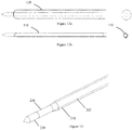
- the inner conductor of the distal portion of the feeding cable 204a is coupled to the applicator 202 as shown in the detailed view of Figure 8 .
- a distal end of the distal portion of the feeding cable is connected to a proximal end of the applicator 202.
- the inner conductor may be attached to the applicator 202 to ensure efficient transfer of electromagnetic energy to the applicator material.
- the applicator 202 may be formed from a ceramic material with suitable dielectric properties (for example zirconia) according to the energy it is arranged to apply.
- An internal bore may be provided in the applicator 202 to receive a portion of the inner conductor to ensure a strong mechanical joint that may also be glued in position.
- the applicator 202 may further be coupled to the tube 226 housing the feeding cable where it is provided.
- the proximal end of the applicator 202 may be connected to the tube 226 via a bore to receive the tube or a set of interlocking fingers to maximise the mechanical strength of the bond between them.
- any other suitable connection means between the tube 226 and the applicator 202, or the distal portion of the feeding cable 204a and the applicator 202 may be provided.
- the applicator 202 may further comprise one or more coolant channels 232 fluidly connected to the coolant delivery path.
- the channels may be formed in the applicator 202 as shown in the close up view of the applicator 202 shown in Figure 9 .
- the channels 232 may allow the cooling fluid to flow past the applicator surface toward the distal tip of the applicator 202 (e.g. along part of or all of the length of the applicator 202).
- a thin layer of material for example a polymer heat shrink
- the one or more channels 232 in the applicator may extend partially along the length of the applicator from the proximal end as shown in Figure 9 to target the cooling fluid to allow a controlled ablation heating zone to be generated.
- the ablation probe 202 may comprise a pointed tip adapted to pierce tissue during use.
- the distal end of the applicator 202 may form the pointed tip (labelled 234 in Figure 9 ).
- the distal tip of the applicator 202 may therefore be pointed to ensure the applicator 202 can effectively pierce through tissue for delivery to the ablation site.
- the ablation probe 200 may further comprise a coupling member 236 formed from an electrically insulating material.
- the coupling member 236 may be coupled to the distal end of the applicator 202.
- a separate tip member 238 comprising a pointed tip is coupled to the coupling member 336 to form the pointed tip at the distal end of the ablation probe 200.
- the tip member 238 and the coupling member 236 may be formed by a single component.
- the coupling member 236 may be formed from a material with a low electrical permittivity (e.g. a polymer).
- heating effects may be confined (or partly confined) to the applicator 202, thus providing a cool portion onto which the deformable member 210 can be bonded such that it is coupled to the applicator 202 via the coupling member 236.
- the flexural stiffness of the coupling member 236 may be chosen to optimise the flexibility of the ablation probe 200 to facilitate delivery within a tortuous anatomy (for example in the lung).
- a coupling member may additionally or alternatively be provided at the proximal end of the applicator 202 to provide a coupling between the deformable member and the proximal end of the applicator 202.
- the probe may comprise a blunt tip adapted to prevent or reduce the piercing of tissue during use.
- the applicator 202 or coupling member 236 may have a blunt distal end which is less likely to pierce tissue during use. This may be advantageous for some treatment sites such as in the lungs.
- the needle portion further comprises the deformable member 210 as shown in the exploded view of Figure 3 .
- the deformable member 210 is formed by an inflatable member arranged to move between a deflated configuration when the deformable member 210 is in the insertion configuration and an inflated configuration when the deformable member 210 is in the deployed configuration.
- the inflatable member may thus form a balloon which may be inflated by the flow of coolant (e.g. the inflatable member may inflate due to the pressure of the coolant).
- the inflatable member has an inside diameter that matches the outside diameter of the tube 226 (or the membrane 228 surrounding the tube 228 or the outer conductor or insulating material respectively).
- the inflating member may inflate to a larger diameter when the cooling system is pressurised. This may therefore form a conduit for the cooling fluid to return from the applicator 202.
- some, or all, of the inflating member may change shape (e.g. expand) to allow space for the coolant to flow.
- the inflation member is deflated, the insertion profile of the ablation probe 200 may be reduced (e.g. minimised) to aid delivery to the target ablation site.
- the inflation member may be deflated so that it returns to its original diameter to facilitate removal.
- the inflatable member may be arranged to inflate or expand to a maximum threshold size in the inflated deployed configuration. This may facilitate easy insertion of the ablation probe 200.
- the inflatable member may comprise a compliant or semi-compliant material arranged to expand or contract in size in order to move between the deflated insertion and inflated deployed configurations.
- the inflatable member material and geometry may have the necessary properties to allow it to expand by a suitable amount and elastically to return to its original shape or diameter.
- a vacuum may be applied to the coolant return path after therapy delivery to help the inflatable member to collapse and aid removal of the ablation probe 200.
- the vacuum may be provided in addition to, or to replace, the elastic function of the inflatable member.
- the inflatable member may be formed from a thin wall material to minimise the overall profile of the ablation probe 200.
- the inflatable member may have low friction properties or may be coated with a lubricious material (for example parylene) to aid insertion.
- the inflatable member material (or coating) may also allow the inflatable member to be easily separated from the other components forming the ablation probe when it inflates (e.g. the membrane).
- An example of the compliant or semi-compliant deformable member 110 moving from the deflated to the inflated configurations is shown schematically in Figures 11a and 11b .
- the inflatable member may be formed from a non-compliant material arranged to fold or unfold in order to move between the deflated insertion and inflated deployed configurations.
- the inflatable member may be wrapped and/or folded when deflated and unfurls when pressurised by the cooling fluid.
- the inflatable member may, for example, be compactly folded before use of the ablation probe to provide a compact insertion configuration.
- a folded portion of the inflatable member may be stored within a channel (e.g. in the tube 226) to minimise the insertion profile of the ablation probe 200 when in the insertion configuration.
- the use of a non-compliant material may allow an inflatable member with a larger deployed size, or stepped/tapered profile as will be described later.
- the inflatable member may be adapted to optimise the wall thickness and minimise the overall profile of the ablation probe.
- the inflatable member may be manufactured by blow moulding a preform to give the desired shape.
- the preform may be shaped such that a thin walled inflatable member is produced once it has been blown into the mould.
- the preform may be shaped, e.g. by grinding, to control the wall thickness of the inflatable member once blown into the mould. This can be used to achieve low wall thickness in portions of the inflatable member where there is low stretch ratio, e.g. in the edges (e.g. sleeves) of the inflatable member.
- a vacuum may again be used to collapse the deformable member once ablation therapy is complete.
- the inflatable member When refolded using a vacuum the inflatable member may not return to the same neat folded configuration it started in before insertion, but may collapse sufficiently to allow removal of the ablation probe.
- An example of the non-compliant inflatable member moving from the deflated to the inflated configurations is shown schematically in Figures 12a and 12b .
- the inflatable member may be formed from a mixture of compliant, semi-compliant and non-compliant materials.
- the deformable member 110 may extend along at least part of the length of the needle portion 212 as shown in the Figures.
- the deformable member 110 may, for example, extend from at or near the boundary between the needle portion 212 and the catheter portion 214 and end at or near the proximal end of the applicator 202.
- the deformable member 210 may be fluidly connected to the non-deformable coolant return conduit at a boundary between the needle portion 212 and the catheter portion 214. The coolant may therefore flow through the deformable member 110 (when in the deployed configuration) and then through the non-deformable coolant return conduit in the catheter portion to reach the proximal end of the ablation probe 200.
- the deformable member may terminate at or near the proximal end of the applicator 202.
- the distal end of the deformable member may be coupled to the tube 226, a proximal portion of the applicator 202, or a separate coupling member as previously described.
- the deformable member 110 is arranged to at least partly surround the applicator 202 as shown in Figure 13 .
- the applicator 202 is therefore located at least partly within the deformable member 210 and is therefore surrounded by the cooling fluid. This may help to reduce charring effects in surrounding tissue during therapy delivery.
- the cooling fluid may be water or a similar substance with a suitable electrical permittivity to effectively transfer of the microwave energy into the surrounding tissue.
- the deformable member 210 may surround all of the circumference of the ablation probe 200 as shown Figure 13 to form a coolant conduit around the tube 226 (and membrane 228 and/or applicator 202 respectively) when in the deployed configuration. In other embodiments, the deformable member 210 may surround only part of the tube 226 (and membrane 228 and/or applicator 202 respectively).
- the deformable member 210 comprises one or more elongate deformable channels 240 running along at least part of the length of the ablation probe 200.
- the one or more deformable channels 240 may comprise a plurality of channels equally spaced around a circumference of the ablation probe 200 as shown in Figure 13 . In the described embodiment, four equally spaced deformable channels may be provided.
- the deformable channels 240 may be arranged in between the channels 230 forming the coolant delivery path. In other embodiments, any or suitable arrangement, number, or geometry of channels may be provided.
- the deformable channels 240 may be linked by a portion or portions of the inflatable member which do not change shape when the inflatable member moves to the inflated configuration. These non-inflatable portions may be arranged to cover the channels 230 in the tube 226 to provide a boundary of the coolant delivery path. This may mean that the membrane is not required (e.g. it is replaced by a non-expanding portion(s) of the inflatable member). An example of this is shown in Figure 15 . In this embodiment, four deformable channels 240 are provided around the circumference of the ablation probe (shown in a deployed or inflated state in Figure 15 ). The deformable channels 240 are interspersed by four channels 230 in the tube 226.
- the channels 230 are equally spaced at 12 o'clock, 3 o'clock, 6 o'clock, and 9 o'clock positions, with the deformable channels 240 spaced equally between them.
- the channels and deformable channels may have other numbers and arrangements and may not be equally spaced.
- the deformable member 210 may be arranged, when in the deployed configuration, to control any one or more of the shape, size and position of an ablation zone produced by the applicator 202.
- the shape and position of the deformable member 210 when in the deployed configuration may be adapted to control the ablation zone.
- the deformable member 210 may be adapted to provide an advantageous ablation zone to efficiently heat the tissue which is to be treated, and to reduce the heating of other tissue.
- the deformable member 210 in the second configuration is arranged to generate a generally spherical ablation zone. This may provide a uniform distribution of energy over the ablation zone and provide improved heating.
- other shaped ablation zones may be generated by appropriate size, shape and positioning of the deformable member 210.
- the deformable member 210 when in the deployed configuration, may have a larger size at or near a proximal end of the applicator 202 to control the ablation zone. This may ensure a significant volume of the cooling fluid is positioned adjacent to the proximal end of the applicator 202 to provide a heat sink to control heating effects and, therefore, the shape of the ablation zone.
- the deformable member 210 forms any one of a non-uniform tapered, bulbous or conical shape when in the deployed configuration to control the ablation zone. An example of this can be seen in Figure 16 where a large diameter section 210a of the deformable member 210 is provided to control the ablation zone.
- the deformable member 210 may be arranged such that movement to the deployed configuration causes flexing of the ablation probe 200 to direct the energy applied by the applicator 202.
- the deformable member 210 may be arranged to direct the applicator 202 to deliver energy in a directed orientation.
- the deformable member may bias the bending of the ablation probe through the biasing of the deformable member position and/or its material properties.
- the inflation of the deformable member 210 may thus cause bending or flexure of the ablation probe 200 so as to direct the energy. This may be achieved by coupling the deformable member on one side of the ablation probe 200 (e.g.
- FIG. 17a an off-axis deformable member is shown. When the off axis deformable member is deployed the ablation probe may flex as shown in Figure 17b .
- the deformable member 210 When in the deployed configuration, the deformable member 210 may be shaped to anchor the ablation probe relative to the surrounding tissue. The deformable member 210 may therefore act to provide a return path for coolant along as well as anchoring the ablation probe. The may avoid the need for a second anchoring means, which may reduce the size of the ablation probe 200. By anchoring the ablation probe 200, the deformable member 210 may act to combat undesirable movement of the applicator 202 during the ablation procedure. It may, for example, reduce movement due to the displacements associated with breathing.
- the deformable member 210 profile when in the deployed configuration may be optimised (for example by adding a bulbous or tapered section) to further improve anchoring and as well as mitigating undesirable heating effects that influence the ablation zone as described above.
- the deformable member 210 may therefore provide a number of different functions (return flow of coolant and/or control of the ablation zone and/or anchoring) in a single structure. This may reduce the overall size of the ablation probe 200.
- additional anchoring may be provided through the use of a separate anchoring mechanism (not shown in the Figures).
- the anchoring mechanism may comprise a helical wire or hollow screw thread at the distal portion of the antenna. This helical wire may act to anchor the antenna 202 in position by rotating the ablation probe 200 such that the screw is anchored into the adjacent tissue.
- the helical screw anchor may be male or female in construction and may be located distal to or concentric with the distal tip of the antenna 202.
- the material used for the anchor may be selected to ensure it is compatible with the energy modality and applicator configuration. For example, a non-metallic material may be used if a microwave probe is used.
- the ablation probe 200 may comprise one or more sensors (not shown in the figures) arranged to sense whether the deformable member has moved into the deployed configuration.
- the sensor(s) may be arranged to sense one or more properties of the applicator 202 or the energy applied to the surrounding tissue to determine the configuration of the deformable member 210.
- the successful inflation of the deformable member 210 may be determined by monitoring the reflected power from the applicator, which is minimised only when the deformable member 210 is inflated. This may be used to provide feedback to the physician during therapy delivery.
- the deformable member 210 behaviour may also be determined by monitoring the pressure of the cooling fluid. For example, when the cooling fluid is pressurised, it can be inferred that the deformable member 210 is inflated and when a vacuum is applied it is deflated.
- the volume of the coolant may be used to determine the status of the deformable member, where the volume of cooling fluid delivered is used to determine if the deformable member has inflated correctly.
- the ablation probe 200 may comprise a sensor or series of sensors to monitor tissue properties to ensure correct placement of the device or track the progress of the ablation.
- the sensor(s) may comprise temperature sensor(s) (e.g. thermocouples) or an electrical impedance sensor(s).
- the sensor(s) may be provided at any suitable location in the ablation probe 200.
- the sensor(s) may be provided within the deformable member 210 (e.g. may be within one of the deformable channels shown in Figure 15 ).
- the geometry of the deformable member 210 may be optimised to facilitate the sensor placement and provide suitable feedback on the tissue properties and ablation process.
- the sensor(s) may be positioned in the wall of the deformable member 210, or in the coolant return path formed by the deformable member 210. In other embodiments, the sensor(s) may be provided within the coolant return path or within the applicator 202.
- the ablation probe 200 may further comprise a separate choke element.
- the choke element may be disposed at the distal end of the applicator 202 so as to control the shape of the ablation zone.
- the choke element may be formed at least partly from a flexible material so as not to impede the overall flexibility of the ablation probe.
- the choke element may be formed from a mixture of a ceramic and a metallic material.
- the choke element may be positioned such that it is cooled by the coolant flowing via the coolant delivery path to help keep the choke cool during use.
- the choke element may, for example, be integrated with the tube housing the feeding cable to provide a compact arrangement.
- the choke element 242 may form a short circuited balun which is active at microwave frequencies.
- the choke element 242 may be integrated at the proximal end of the applicator 202 where it is attached to the tube 226 housing the feeding cable 204a.
- the choke element 242 may be active when the ablation probe operates with microwave ablation energy.
- the choke element 242 may provide a high impedance condition at or near the proximal end of the applicator 202 to minimise reflected power flowing along the conductor.
- the choke element 242 may be formed by the insertion of the material forming the applicator between the tube 226 housing the feeding cable.
- the applicator material may extend for a distance of about one-quarter wavelength from the distal end of the tube 226 housing the feeding cable to the distal end of the outer conductor (e.g. the applicator material may overlap the outer conductor).
- the portion of the applicator material extending over the feeding cable 204 may be formed by one or more finger portions (two of which are shown in Figure 18 ) extending from the proximal end of the applicator 202.
- an electrical connection may be made between the outer conductor of the feeding cable 204 and the tube 226 housing the feeding cable at a distance of about one-quarter wavelength proximally from a distal end of the tube.
- the term "wavelength" refers to the wavelength of electromagnetic energy corresponding to the operating frequency of the ablation probe.
- the choke element 242 may be miniaturised so as not to impair the flexibility of the ablation probe 200. In yet further embodiments, the choke element 242 may be cooled by the coolant delivery or return path to mitigate over heating during the treatment process.
Abstract
An ablation probe (100; 200), comprising: an applicator (102; 202) arranged to apply radiation to heat surrounding tissue; a feeding cable (104; 204) arranged to supply electromagnetic energy to the applicator (102; 202); a first coolant flow path (106) via which coolant is able to flow; and a deformable member (110; 210) arranged to move between an insertion configuration in which insertion of the probe is facilitated and a deployed configuration, wherein a second coolant path (108), via which coolant is able to flow, is provided by the deformable member (110; 210) when in the deployed configuration.
Description
- This application relates to an ablation probe. In particular, this application relates to an ablation probe that may be used to generate heat within tissue to destroy tissue growths.
- Thermal ablation can be used to destroy tissue growths within the body which can be malignant. Current ablation systems use applicators that deliver Radio Frequency (RF) energy (or microwave energy) to the tissue surrounding the applicator tip. This causes localised heating and destruction of the malignant cells. These applicators may be designed for percutaneous delivery and are therefore relatively short in length and large in diameter. However, many disease locations cannot be safely or easily accessed percutaneously. For example, the location of the pancreas behind the liver makes it difficult to access percutaneously. Similarly, access to the lung through the chest wall can cause a pneumothorax. Large diameter applicators may also cause undesired tissue damage during insertion. This limits the range of indications where thermal ablation therapy can be successfully delivered using existing percutaneous applicators.
- An endoscope can be used to access a number of disease locations that border the gastrointestinal tract. These include the pancreas, biliary tree, lymph nodes and a number of significant blood vessels. Furthermore, Endoscopic Ultrasound (EUS) systems provide a means of identifying lesions in tissue adjacent to the gastrointestinal tract using an ultrasound imaging system that is integrated within the endoscope. A biopsy needle can be delivered through the EUS system and directed to the target site under ultrasound guidance. Similar endoscopes are available to assess disease locations in the lung using both ultrasound and navigation systems. This technology can be used to guide an extended working channel or steerable catheter to the disease location. Known applicator designs are not particularly suited for delivery through the working channel of an endoscope as they are typically too large in cross section and are of insufficient length and flexibility.
- There are significant challenges associated with miniaturising and extending the length of ablation applicators (particularly microwave applicators) to make them suitable for endoscope delivery. Smaller devices can carry less power due to electrical losses in the power cable used to supply energy to the applicator tip. Electrical losses reduce power that reaches the applicator tip, meaning less heat is generated at the tip and the therapy takes longer to deliver. These losses are manifested as heat along the length of the cable and must be controlled using a cooling system to prevent damage to the cable or endoscope, or injury to the patient. To maintain cooling along the length of a narrow cable, a high pressure cooling fluid is required. Furthermore, the applicator must have a minimal profile and favourable mechanical properties to pierce into the organ and reach the target lesion.
- In one aspect, the present application provides an ablation probe, comprising: an applicator arranged to apply radiation to heat surrounding tissue; a feeding cable arranged to supply electromagnetic energy to the applicator; a first coolant flow path via which coolant is able to flow; and a deformable member arranged to move between an insertion configuration in which insertion of the probe is facilitated and a deployed configuration, wherein a second coolant path, via which coolant is able to flow, is provided by the deformable member when in the deployed configuration.
- When the deformable member is in the insertion configuration, the ablation probe may have a profile suitable to aid insertion. This may be a small and compact profile, or a suitable shape or geometry. In the insertion configuration, the ablation probe may be inserted into tissue while reducing undesired tissue injury. The insertion profile may also aid delivery of the ablation probe via an endoscope. Once in the desired position, the deformable member may be moved to the deployed configuration to provide a return coolant path. The ablation probe may therefore have a small profile during insertion when cooling is not required. Once in position, the deformable member may be deployed to then provide cooling during use of the ablation probe.
- Optionally, the second coolant path is provided only by the deformable member along at least a portion of a length of the probe.
- Optionally, the deformable member is fluidly connected to a distal end of the first coolant path.
- Optionally, a distal portion of the feeding cable has a distal cross sectional size, and a proximal portion of the feeding cable has a proximal cross sectional size, wherein the distal cross sectional size is less than the proximal cross sectional size.
- Optionally, the probe comprises: a) needle portion comprising the deformable member, the applicator, the distal portion of the feeding cable and a distal portion of the first coolant path; and b) a catheter portion comprising a proximal portion of the feeding cable, the proximal portion of the first coolant path, and a non-deformable coolant conduit, wherein the deformable member is fluidly connected to the non- deformable coolant conduit at a boundary between the needle portion and the catheter portion.
- Optionally, the deformable member is arranged to at least partly surround the applicator in the deployed configuration.
- Optionally, when in the deployed configuration, the deformable member is shaped to anchor the ablation probe relative to the surrounding tissue.
- Optionally, the deformable member comprises one or more elongate deformable channels running along the length of the ablation probe.
- Optionally, the one or more deformable channels comprise a plurality of channels equally spaced around a circumference of the ablation probe.
- Optionally, the deformable member is arranged to expand to a maximum threshold size in the deployed configuration.
- Optionally, the deformable member comprises: a) a compliant or semi-compliant material arranged to expand or contract in size in order to move between the insertion and deployed configurations; and/or b) a non-compliant material arranged to fold or unfold in order to move between the insertion and deployed configurations.
- Optionally, the ablation probe further comprises a coupling member formed from an electrically insulating material, the coupling member arranged to couple the deformable member to the applicator.
- Optionally, the first coolant path comprises a coolant channel formed between an inside surface of a tube surrounding the feeding cable and an outside surface of the feeding cable.
- Optionally, the first coolant path comprises one or more coolant channels formed in the body of a tube housing the feeding cable.
- Optionally, the feeding cable comprises an inner conductor arranged to transmit a signal to the applicator, the inner conductor being surrounded by an insulating material, and an outer conductor arranged to shield the inner conductor, and wherein the first coolant path comprises one or more coolant channels formed in the outer conductor.
- Optionally, the one or more coolant channels comprise one or more slots in an outer surface of the tube or an outer surface of the outer conductor and wherein the ablation probe further comprises a membrane disposed around the tube or the outer conductor, the membrane arranged to separate the first coolant path and from the second coolant path,
- Optionally, the one or more coolant channels are disposed along a length of the outer conductor or along a length of the tube surrounding the feeding cable.
- Optionally, the one or more coolant channels comprise a plurality of channels spaced equally around a circumference of the outer conductor or tube surrounding the feeding cable. Optionally, the plurality of channels comprises four channels spaced equally around the circumference of the outer conductor or the tube.
- Optionally, the applicator further comprises one or more coolant channels fluidly connected to the first coolant path.
- Optionally, ablation probe further comprises a sensor arranged to sense whether the deformable member has moved into the deployed configuration.
- Optionally, the sensor is arranged to sense one or more properties of the applicator or the energy applied to the surrounding tissue to determine the configuration of the deformable member.
- Optionally, the one or more sensors are provided within the deformable member.
- Optionally, the one or more sensors comprise one or more temperature sensors and/or one or more impedance sensors.
- Optionally, the probe further comprises a choke element disposed at a proximal end of the applicator.
- Optionally, the choke element is formed at least partly from a flexible material, and preferably wherein the choke is formed from a mixture of a ceramic and a metallic material.
- Optionally, the choke element is cooled by the coolant flowing via the first coolant path. Optionally, the choke element is integrated with a tube housing the feeding cable. Optionally, the choke element comprises a portion of the applicator extending between the outer conductor of the feeding cable and a tube housing the feeding cable and preferably extending a distance equivalent to one quarter of a wavelength of the radiation applied by the applicator. Optionally, the feeding cable is formed by an outer and an inner conductor, and wherein an electrical connection is formed between the outer conductor and a tube housing the conductor, and preferably formed at a distance of about one-quarter wavelength of the radiation applied by the applicator proximally from a distal end of the tube.
- Embodiments of the invention will now be described, by way of example only, with reference to the accompanying drawings, in which:
-
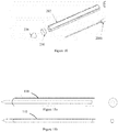
Figures 1a and 1b show a schematic view of part of an ablation probe according to an embodiment; -
Figure 2 shows a perspective view of an ablation probe according to an embodiment; -
Figure 3 shows an exploded view of a needle portion of the ablation probe shown inFigure 2 ; -
Figure 4 shows an exploded view of a catheter portion of the ablation probe shown inFigure 2 ; -
Figures 5a, 5b, and 5b show cross section views through a catheter portion of an ablation probe according to different embodiments; -
Figure 6 shows a close up view of the boundary between the needle portion and the catheter portion of the ablation probe shown inFigure 2 ; -
Figure 7 shows a close up view of a tube forming part of the ablation probe shown inFigure 2 ; -
Figure 8 shows another close up view of an embodiment of an applicator which may form part of the ablation probe shown inFigure 2 ; -
Figure 9 shows a close up view of an applicator forming part of the ablation probe shown inFigure 2 ; -
Figure 10 shows a close up view of a part of a needle portion of an ablation probe according to an embodiment; -
Figures 11a and 11b show schematic side and cross section views of an inflation member of the ablation probe of an embodiment moving between an inflated and deflated configuration; -
Figures 12a and 12b show schematic side and cross section views of an inflation member of the ablation probe of another embodiment moving between an inflated and deflated configuration; -
Figure 13 shows another close up view of a part of a needle portion of an ablation probe according to an embodiment; -
Figure 14 shows another close up view of a part of a needle portion of an ablation probe according to an embodiment; -
Figure 15 shows a cross section through a needle portion of an ablation probe according to an embodiment; -
Figure 16 shows another close up view of a part of a needle portion of an ablation probe according to an embodiment; -
Figures 17a and 17b show an off-axis deformable member according to an embodiment; and -
Figure 18 shows another close up view of a choke element according to an embodiment. - An
ablation probe 100 according to one embodiment is shown schematically inFigures 1a and 1b . Theablation probe 100 of the present disclosure may be suitable for insertion into the body to reach a desired treatment site, such as a malignant tissue growth. Theablation probe 100 may be used endoscopically in order to reach a variety of disease locations within the body. The ablation probe may therefore have an overall flexibility such that it can be inserted through the working channel of the endoscope. In other embodiments, theablation probe 100 may also be used percutaneously, or using any other suitable technique, e.g. inserted through an existing aperture of the body. For percutaneous use, the ablation probe may be generally rigid so that it can be inserted. - The
ablation probe 100 comprises anapplicator 102 arranged to apply radiation to heat surrounding tissue. The applied radiation may be adapted to cause localised heating and destruction of malignant cells around or near to theapplicator 102. Theapplicator 102 may be arranged to apply any suitable form of radiation to surrounding tissue such that the desired heating is caused. Theapplicator 102 may, for example, be arranged to emit microwave or RF radiation, or may emit any other suitable radiation to cause heating. Theapplicator 102 may be arranged at or near a distal end of theablation probe 100 so that it can be positioned in a desired position relative to the tissue to be treated. In the following, the terms "distal" and "proximal" are taken relative to the user operating the ablation probe and the treatment site when the ablation probe is positioned for use - the distal end of theablation probe 100 is that closest to the treatment site and the proximal end is that closest to the user. A control means (not shown in the Figures) such as a handle may be provided at the proximal end of theablation probe 100 so that it can be manipulated and positioned by the user. - The
ablation probe 100 further comprises a feedingcable 104 which is arranged to supply electromagnetic energy to theapplicator 102. The feeding cable may be any elongate member suitable for supplying electromagnetic energy to the applicator (e.g. a conductor). The feedingcable 104 may run along at least part of the length of theablation probe 100 to deliver a supply of energy to theapplicator 102. In the described embodiment, a distal end of the feedingcable 104 is coupled to a proximal end of theapplicator 102 and a proximal end of the feedingcable 104 is coupled to a generation means (not shown inFigures 1a or 1b ) suitable for generating the desired signal to supply energy to theapplicator 102. - The
ablation probe 100 further comprises a first coolant path. In the described embodiment, the first coolant path is acoolant delivery path 106 via which coolant is able to flow towards theapplicator 102. For example, thecoolant delivery path 106 may deliver a flow of coolant towards the distal end of theablation probe 100 from a coolant supply means (not shown in the Figures) coupled to thecoolant delivery path 106 at the proximal end of theablation probe 100. The flow of coolant may help control the temperature of theablation probe 100 during use. This may allow energy to be delivered to the surrounding tissue for an extended period of time without theablation probe 100 overheating and being damaged, or causing injury to healthy tissue. The coolant delivery path may be formed by one or more coolant channels as will be described later. The coolant may be a fluid, and may be water, saline solution, a cryogenic gas or any other suitable coolant known in the art. - The
ablation probe 100 further comprises a second coolant path. In the described embodiment, the second coolant path is acoolant return path 108 via which coolant can return from the applicator. Thecoolant return path 108 may therefore return the supply of coolant from the distal end of theablation probe 100 to the proximal end. Theablation probe 100 further comprises adeformable member 110 which is arranged to move between an insertion configuration (shown inFigure 1a ) in which insertion of theablation probe 100 is facilitated and a deployed configuration (shown inFigure 1b ). When in the deployed configuration, thecoolant return path 108 is provided by thedeformable member 110. In some embodiments, no coolant return path may be provided when the deformable member is in the insertion configuration. This may allow the profile of the ablation probe to be minimised. In other embodiments, the return path may not be completely absent when the deformable member is in the insertion configuration. The insertion configuration therefore provides a configuration in which theablation probe 100 may be suitable for delivery to the desired location within the body. The insertion configuration may, for example, correspond to a suitable size and/or shape adapted to allow insertion with reduced risk of undesired tissue damage. When in the insertion configuration, theablation probe 100 may, for example, have a low profile (e.g. small cross sectional size) for ease of insertion through tissue without causing injury or insertion through the working channel of an endoscope. - In other embodiments, the first coolant path may act as a coolant return path. In this embodiment, the first coolant path is arranged to carry a flow of coolant away from the applicator. In this embodiment, the second coolant path may act as a coolant delivery path arranged to carry a flow of coolant towards the applicator. A combination of the first and second coolant paths may therefore form a coolant circuit arranged to deliver a flow of coolant to and away from the applicator, where the coolant can flow in either direction along each of the first and second coolant paths. In the embodiment shown in the figures, the first coolant path acting as the coolant delivery path may allow a flow of colder coolant close to the feeding cable. This may aid cooling of the ablation probe as a significant amount of heat may be generated in the feeding cable. In other embodiments, where the second coolant path acts as the coolant delivery path, colder coolant may be delivered to the applicator first to aid cooling of the applicator.
- The
ablation probe 100 may therefore be delivered to the desired location whilst thedeformable member 110 is in the insertion configuration. Once at the desired location, thedeformable member 110 may be moved to the deployed configuration to allow flow of the coolant away from theapplicator 102. The coolant can then flow via the coolant delivery and return paths to cool theablation probe 100 during use. Thedeformable member 110 therefore is able to provide an insertion configuration suitable for delivery to the ablation site when the coolant flow is not required. Once the ablation probe is in position, thedeformable member 110 may be moved to a configuration suitable to provide a flow of coolant as required during delivery of energy from theapplicator 102. When in the deformable member is in the insertion configuration the overall diameter of the ablation probe may be between about 13 to about 25 gauge (approximately 2.5 to 0.5 mm). This may allow easy insertion. - As can be seen in
Figures 1a and 1b , thecoolant return path 110 may be provided only by the deformable member along at least a portion of a length of theablation probe 100. For example, along at least part of the length of theablation probe 100, no other channels or conduits to carry returning coolant may be provided in addition to thecoolant return path 108 formed by thedeformable member 110. This may allow theablation probe 100 to have a small cross sectional size when the deformable member is in the insertion configuration. Any additional coolant return paths would require additional space within the body of theablation probe 100 and so would not provide a low profile. - In the embodiment of
Figures 1a and 1b , thedeformable member 110 is fluidly connected to a distal end of the coolant delivery path 106 (e.g. the distal end of the coolant delivery path may be joined to the distal end of the fluid return path to form a single path along which coolant may flow towards and then away from the applicator (in either direction)). Thecoolant delivery path 106 therefore runs along the inside of thecoolant return path 108 when thedeformable member 110 is in the deployed configuration. This arrangement allows the overall size of theablation probe 100 to be reduced when thedeformable member 110 is in the insertion configuration. - An example embodiment of an
ablation probe 200 according to this disclosure is shown in more detail inFigures 2 to 8 . The embodiment shown in the Figures is only one such example. - As can be seen in
Figure 2 , in this embodiment, theablation probe 200 generally comprises two portions: aneedle portion 212 and acatheter portion 214. Theneedle portion 212 may be arranged at the distal end of theablation probe 200 and is adapted to be inserted into tissue during use to reach the desired ablation location. Thecatheter portion 214 may be provided at the proximal end of theablation probe 200 and is arranged to supply electromagnetic energy and a flow of coolant to and from theneedle portion 212. In the embodiment shown in the Figures, theablation probe 200 further comprises ahandle portion 216 via which the ablation probe may be manipulated and positioned during use. The catheter portion may have an extended length and flexibility for endoscopic use as shown inFigure 2 . In other embodiments, a shorter, more rigid catheter portion may be provided for percutaneous use. - In some embodiments, the needle portion may form a small part of the overall length of the ablation probe. For example, the needle portion may be approximately 5 mm to 2000 mm in length, and preferably may be around 70 mm in length. The length of the needle portion may be chosen according to the anatomy to be accessed. A length of around 70 mm may be advantageous for providing good access to ablation sites in the pancreas. A longer length of needle portion may be more suitable for accessing parts of the lung, for example. The catheter portion may be around 1000 mm to 2000 mm in length, and preferably around 1400 mm in length. The length of the catheter portion may be chosen according to the position of the ablation site which must be reached. In other embodiments, the needle portion of the ablation probe (e.g. that having the deformable member) may form a greater proportion of the length of the ablation probe. In some embodiments, the entire length of the ablation probe may be formed by the needle portion. In such an embodiment, the deformable member may extend along the majority or all of the length of the ablation probe. In such an embodiment, the catheter portion may not be required. For example, if the ablation probe is to be used percutaneously the catheter portion may be shorter than for endoscopic use, or may not be required.
- An exploded view of the needle portion is shown in
Figure 3 . Theneedle portion 212 may comprise adeformable member 210, anapplicator 202, a distal portion of the feedingcable 204a and a distal portion of the coolant delivery path. An exploded view of the catheter portion is shown inFigure 4 . In this embodiment, thecatheter portion 214 may comprise a proximal portion of the feedingcable 204b, a proximal portion of the coolant delivery path, and a coolant return conduit (which may be non-deformable). The proximal portion of the coolant delivery path may be formed by a space between atube 218 housing the proximal portion of the feedingcable 204b and a surroundingcoolant delivery tube 220. The coolant return path may be formed by a space between thecoolant delivery tube 220 and a surroundingcoolant return tube 222. In other embodiments, any other suitable arrangement of channels or conduits may be provided to form the coolant return and coolant delivery paths within thecatheter portion 214. - Examples of suitable arrangements of channels forming the coolant return and coolant delivery paths are shown in the cross sectional views of
Figures 5a to 5c . InFigure 5a , the catheter portion comprises two lumens each forming one of the coolant return and coolant delivery paths. InFigure 5b , the catheter portion comprises four lumens forming the coolant return path and coolant delivery path. Two of the lumens may form the coolant return path, and two of the lumens may form the coolant delivery path. This embodiment may provide better kink resistance and strength. The lumens may not be equally sized as shown inFigures 5a and 5b . An example of this is shown inFigure 5c in which three lumens are provided. A first and second lumen may provide the coolant return and delivery paths, with the third lumen provided to include other components such as a sensor or the like. The third lumen may be small in size compared to the first and second lumens to provide adequate space for the flow of coolant. - In the described embodiment, the feeding cable is formed by two lengths of cable (the
distal portion 204a and theproximal portion 204b) joined at the boundary between theneedle portion 212 and the catheter portion 214 (shown in more detail in the close up view ofFigure 6 ). The feeding cable may be formed by two lengths of coaxial cable to form an electrical circuit to deliver electromagnetic energy to theapplicator 202. In other embodiments, any other suitable conductor may be provided to deliver a supply of suitable electromagnetic energy to theapplicator 202. Theablation probe 200 may further comprise aconnector 224 arranged to mechanically and electrically splice the distal portion of the feedingcable 204a to the proximal portion of the feedingcable 204b. Theconnector 224 may connect the different portions of the feedingcable ablation probe 200. In the described embodiment, the distal portion of the feedingcable 204a has a corresponding distal cross sectional size, and a proximal portion of the feedingcable 204b has a corresponding proximal cross sectional size, wherein the distal cross sectional size is less than the proximal cross sectional size. The size (e.g. diameter) of the conductor is therefore optimised based on its position within theablation probe 200. The cross sectional sizes may be chosen to optimise (e.g. maximise) the feeding cable power handling, while also reducing electrical losses and optimising the mechanical strength of theablation probe 200. In other words, the length of the smaller cross section portion of the feeding cable is minimised by connecting it to a larger cross section feeding cable (e.g. a more efficient cable) for the portion of theablation probe 200 outside of theneedle portion 212. This part of theablation probe 200 does not need to be inserted into tissue so a small profile is not as important. The cross section of the feeding cable in thecatheter portion 212 is therefore increased to reduce power loss where a small cross section is less important. - The
needle portion 212 may further comprise a tube 226 (e.g. a hypotube) arranged to house the distal portion of the feedingcable 204a. Thetube 226 may be formed from a metal material which has sufficient rigidity to allow theneedle portion 212 to be inserted into tissue. In other embodiments, thetube 226 may be formed from any other suitable material and may be formed from a superelastic material, for example Nitinol. - In one embodiment, the coolant delivery path is provided by a channel formed between the feeding cable and inside wall of the
tube 226. For example, clearance between the feeding cable and the inside wall of thetube 226 may provide space for coolant to flow. In other embodiments, slots may be cut into the inside wall of thetube 226 to provide a space through which coolant can flow. The amount of clearance may be specified to ensure an adequate flow of cooling is achieved while maximising the power carrying capacity of the feeding cable. - In the embodiment shown in the Figures, the coolant delivery path comprises one or more coolant channels formed in the body of the
tube 226. The coolant therefore may partly surround the feeding cable to aid cooling. The width and number of the channels may be chosen to optimise (e.g. maximise) the mechanical strength of theablation probe 100 and the performance of the cooling. - The one or more channels may be cut into the wall of
tube 226 to allow cooling fluid to flow adjacent to the distal portion of the feedingcable 204a. In the described embodiment, the one or more channels may be formed by one or more slots formed in the outer surface of thetube 226. In this embodiment, theablation probe 200 may further comprise amembrane 228 disposed around thetube 226. Themembrane 228 may be arranged to separate the coolant delivery path from the coolant return path (e.g. it forms a boundary between them). In some embodiments, the one or more channels may extend distally past a distal end of themembrane 228 so that coolant can flow from the one or more channels into thedeformable member 210. In other embodiments, one or more apertures may be provided in themembrane 228 to fluidly connect the one or more channels with thedeformable member 210. Themembrane 228 may be formed from a thin layer of material (for example a polymer heat shrink) located over thetube 226 to form an enclosed conduit for the cooling fluid. In other embodiments, the channels may be formed within the wall of thetube 226, in which case themembrane 228 may not be required. - In other embodiments (not shown in the Figures), the distal portion of the feeding
cable 204a may comprise an inner conductor arranged to transmit a signal to theapplicator 202 and an outer conductor arranged to shield the inner conductor (e.g. it may be a coaxial cable). The coolant delivery path may comprise one or more coolant channels formed in the outer conductor. The coolant channels may, for example, be formed by one or more slots in an outer surface of the outer conductor. The coolant and the split outer conductor may thus form a mixed media outer conductor arranged to shield the electrically insulating material. A membrane may be formed around the outer conductor to form a conduit for the cooling fluid. In some embodiments, the feeding cable may be formed by a coaxial cable in which the outer conductor is manufactured from a robust material (for example stainless steel) to form a ridged body of the needle portion. In this embodiment, the coolant delivery path may be formed by channels in the outer conductor, rather than in thetube 228. In such an embodiment, the tube may therefore not be required, thus saving space. In other embodiments, the tube may also be provided. The cooling channels may also more effectively cool the feeding cable as well as deliver coolant to theapplicator 202. In some embodiments, the one or more channels formed in the outer conductor may be aligned with the central axis of the feeding cable. The width and number of the channels may be chosen to optimise the mechanical strength of the feeding cable and the performance of the cooling, while minimising electrical losses and ensuring impedance matching between portions of the feeding cable having channels in the outer conductor and portions of the feeding cable in which the channels are not present (e.g. in the catheter portion). - The one or more coolant channels described above forming the coolant delivery path may be disposed along a length of the ablation probe as can be seen in the close up view of the
tube 226 shown inFigure 7 . In some embodiments, a plurality of channels may be provided such that they are spaced equally around a circumference of the outer conductor ortube 226 housing the feeding cable. InFigure 7 only one of the channels is visible (labelled 230). In some embodiments, the plurality of channels may comprise four channels spaced equally around the circumference of the outer conductor ortube 226 housing the feeding cable. In other embodiments, other numbers and arrangements of channels may be provided according to the cooling requirements and mechanical strength requirements of the ablation probe. - The inner conductor of the distal portion of the feeding
cable 204a is coupled to theapplicator 202 as shown in the detailed view ofFigure 8 . In this embodiment, a distal end of the distal portion of the feeding cable is connected to a proximal end of theapplicator 202. Where the feeding cable is formed from an inner and outer conductor, the inner conductor may be attached to theapplicator 202 to ensure efficient transfer of electromagnetic energy to the applicator material. Theapplicator 202 may be formed from a ceramic material with suitable dielectric properties (for example zirconia) according to the energy it is arranged to apply. An internal bore may be provided in theapplicator 202 to receive a portion of the inner conductor to ensure a strong mechanical joint that may also be glued in position. Theapplicator 202 may further be coupled to thetube 226 housing the feeding cable where it is provided. In such an embodiment, the proximal end of theapplicator 202 may be connected to thetube 226 via a bore to receive the tube or a set of interlocking fingers to maximise the mechanical strength of the bond between them. In other embodiments, any other suitable connection means between thetube 226 and theapplicator 202, or the distal portion of the feedingcable 204a and theapplicator 202 may be provided. - In some embodiments, the
applicator 202 may further comprise one ormore coolant channels 232 fluidly connected to the coolant delivery path. In this embodiment, the channels may be formed in theapplicator 202 as shown in the close up view of theapplicator 202 shown inFigure 9 . Thechannels 232 may allow the cooling fluid to flow past the applicator surface toward the distal tip of the applicator 202 (e.g. along part of or all of the length of the applicator 202). A thin layer of material (for example a polymer heat shrink) may be arranged over the applicator to enclose thechannels 230 and form a conduit for the cooling fluid. This arrangement may reduce the risk of tissue charring at the antenna surface and associated losses in heating performance. In some embodiments, the one ormore channels 232 in the applicator may extend partially along the length of the applicator from the proximal end as shown inFigure 9 to target the cooling fluid to allow a controlled ablation heating zone to be generated. - In the described embodiment, the
ablation probe 202 may comprise a pointed tip adapted to pierce tissue during use. In embodiments where theapplicator 202 is located at the distal end of theablation probe 200, the distal end of theapplicator 202 may form the pointed tip (labelled 234 inFigure 9 ). The distal tip of theapplicator 202 may therefore be pointed to ensure theapplicator 202 can effectively pierce through tissue for delivery to the ablation site. - In other embodiments (as shown in the exploded view of
Figure 10 ), theablation probe 200 may further comprise acoupling member 236 formed from an electrically insulating material. Thecoupling member 236 may be coupled to the distal end of theapplicator 202. In the embodiment shown in the Figures, aseparate tip member 238 comprising a pointed tip is coupled to the coupling member 336 to form the pointed tip at the distal end of theablation probe 200. In other embodiments, thetip member 238 and thecoupling member 236 may be formed by a single component. Thecoupling member 236 may be formed from a material with a low electrical permittivity (e.g. a polymer). In this embodiment, heating effects may be confined (or partly confined) to theapplicator 202, thus providing a cool portion onto which thedeformable member 210 can be bonded such that it is coupled to theapplicator 202 via thecoupling member 236. Furthermore, the flexural stiffness of thecoupling member 236 may be chosen to optimise the flexibility of theablation probe 200 to facilitate delivery within a tortuous anatomy (for example in the lung). In other embodiments, a coupling member may additionally or alternatively be provided at the proximal end of theapplicator 202 to provide a coupling between the deformable member and the proximal end of theapplicator 202. - In other embodiments, the probe may comprise a blunt tip adapted to prevent or reduce the piercing of tissue during use. In such an embodiment, the
applicator 202 orcoupling member 236 may have a blunt distal end which is less likely to pierce tissue during use. This may be advantageous for some treatment sites such as in the lungs. - The needle portion further comprises the
deformable member 210 as shown in the exploded view ofFigure 3 . In the described embodiment, thedeformable member 210 is formed by an inflatable member arranged to move between a deflated configuration when thedeformable member 210 is in the insertion configuration and an inflated configuration when thedeformable member 210 is in the deployed configuration. The inflatable member may thus form a balloon which may be inflated by the flow of coolant (e.g. the inflatable member may inflate due to the pressure of the coolant). In the described embodiment, the inflatable member has an inside diameter that matches the outside diameter of the tube 226 (or themembrane 228 surrounding thetube 228 or the outer conductor or insulating material respectively). The inflating member may inflate to a larger diameter when the cooling system is pressurised. This may therefore form a conduit for the cooling fluid to return from theapplicator 202. When moving to the inflated configuration, some, or all, of the inflating member may change shape (e.g. expand) to allow space for the coolant to flow. When the inflation member is deflated, the insertion profile of theablation probe 200 may be reduced (e.g. minimised) to aid delivery to the target ablation site. When the ablation therapy has been delivered, the inflation member may be deflated so that it returns to its original diameter to facilitate removal. - The inflatable member may be arranged to inflate or expand to a maximum threshold size in the inflated deployed configuration. This may facilitate easy insertion of the
ablation probe 200. In some embodiments, the inflatable member may comprise a compliant or semi-compliant material arranged to expand or contract in size in order to move between the deflated insertion and inflated deployed configurations. The inflatable member material and geometry may have the necessary properties to allow it to expand by a suitable amount and elastically to return to its original shape or diameter. In some embodiments, a vacuum may be applied to the coolant return path after therapy delivery to help the inflatable member to collapse and aid removal of theablation probe 200. The vacuum may be provided in addition to, or to replace, the elastic function of the inflatable member. The inflatable member may be formed from a thin wall material to minimise the overall profile of theablation probe 200. In some embodiments, the inflatable member may have low friction properties or may be coated with a lubricious material (for example parylene) to aid insertion. In some embodiments, the inflatable member material (or coating) may also allow the inflatable member to be easily separated from the other components forming the ablation probe when it inflates (e.g. the membrane). An example of the compliant or semi-compliantdeformable member 110 moving from the deflated to the inflated configurations is shown schematically inFigures 11a and 11b . - In other embodiments, the inflatable member may be formed from a non-compliant material arranged to fold or unfold in order to move between the deflated insertion and inflated deployed configurations. In this embodiment, the inflatable member may be wrapped and/or folded when deflated and unfurls when pressurised by the cooling fluid. The inflatable member may, for example, be compactly folded before use of the ablation probe to provide a compact insertion configuration. A folded portion of the inflatable member may be stored within a channel (e.g. in the tube 226) to minimise the insertion profile of the
ablation probe 200 when in the insertion configuration. The use of a non-compliant material may allow an inflatable member with a larger deployed size, or stepped/tapered profile as will be described later. The inflatable member may be adapted to optimise the wall thickness and minimise the overall profile of the ablation probe. For example, the inflatable member may be manufactured by blow moulding a preform to give the desired shape. The preform may be shaped such that a thin walled inflatable member is produced once it has been blown into the mould. For example, the preform may be shaped, e.g. by grinding, to control the wall thickness of the inflatable member once blown into the mould. This can be used to achieve low wall thickness in portions of the inflatable member where there is low stretch ratio, e.g. in the edges (e.g. sleeves) of the inflatable member. A vacuum may again be used to collapse the deformable member once ablation therapy is complete. When refolded using a vacuum the inflatable member may not return to the same neat folded configuration it started in before insertion, but may collapse sufficiently to allow removal of the ablation probe. An example of the non-compliant inflatable member moving from the deflated to the inflated configurations is shown schematically inFigures 12a and 12b . In yet other embodiments, the inflatable member may be formed from a mixture of compliant, semi-compliant and non-compliant materials. - The
deformable member 110 may extend along at least part of the length of theneedle portion 212 as shown in the Figures. Thedeformable member 110 may, for example, extend from at or near the boundary between theneedle portion 212 and thecatheter portion 214 and end at or near the proximal end of theapplicator 202. Thedeformable member 210 may be fluidly connected to the non-deformable coolant return conduit at a boundary between theneedle portion 212 and thecatheter portion 214. The coolant may therefore flow through the deformable member 110 (when in the deployed configuration) and then through the non-deformable coolant return conduit in the catheter portion to reach the proximal end of theablation probe 200. - In some embodiments, the deformable member may terminate at or near the proximal end of the
applicator 202. In such an embodiment, the distal end of the deformable member may be coupled to thetube 226, a proximal portion of theapplicator 202, or a separate coupling member as previously described. In other embodiments, thedeformable member 110 is arranged to at least partly surround theapplicator 202 as shown inFigure 13 . In such an embodiment, theapplicator 202 is therefore located at least partly within thedeformable member 210 and is therefore surrounded by the cooling fluid. This may help to reduce charring effects in surrounding tissue during therapy delivery. In this embodiment, the cooling fluid may be water or a similar substance with a suitable electrical permittivity to effectively transfer of the microwave energy into the surrounding tissue. - The
deformable member 210 may surround all of the circumference of theablation probe 200 as shownFigure 13 to form a coolant conduit around the tube 226 (andmembrane 228 and/orapplicator 202 respectively) when in the deployed configuration. In other embodiments, thedeformable member 210 may surround only part of the tube 226 (andmembrane 228 and/orapplicator 202 respectively). In one embodiment, as shown inFigure 14 , thedeformable member 210 comprises one or more elongatedeformable channels 240 running along at least part of the length of theablation probe 200. The one or moredeformable channels 240 may comprise a plurality of channels equally spaced around a circumference of theablation probe 200 as shown inFigure 13 . In the described embodiment, four equally spaced deformable channels may be provided. Thedeformable channels 240 may be arranged in between thechannels 230 forming the coolant delivery path. In other embodiments, any or suitable arrangement, number, or geometry of channels may be provided. - In some embodiments, the
deformable channels 240 may be linked by a portion or portions of the inflatable member which do not change shape when the inflatable member moves to the inflated configuration. These non-inflatable portions may be arranged to cover thechannels 230 in thetube 226 to provide a boundary of the coolant delivery path. This may mean that the membrane is not required (e.g. it is replaced by a non-expanding portion(s) of the inflatable member). An example of this is shown inFigure 15 . In this embodiment, fourdeformable channels 240 are provided around the circumference of the ablation probe (shown in a deployed or inflated state inFigure 15 ). Thedeformable channels 240 are interspersed by fourchannels 230 in thetube 226. In this embodiment, thechannels 230 are equally spaced at 12 o'clock, 3 o'clock, 6 o'clock, and 9 o'clock positions, with thedeformable channels 240 spaced equally between them. In other embodiments, the channels and deformable channels may have other numbers and arrangements and may not be equally spaced. - In some embodiments, the
deformable member 210 may be arranged, when in the deployed configuration, to control any one or more of the shape, size and position of an ablation zone produced by theapplicator 202. For example, the shape and position of thedeformable member 210 when in the deployed configuration may be adapted to control the ablation zone. Thedeformable member 210 may be adapted to provide an advantageous ablation zone to efficiently heat the tissue which is to be treated, and to reduce the heating of other tissue. In some embodiments, thedeformable member 210 in the second configuration is arranged to generate a generally spherical ablation zone. This may provide a uniform distribution of energy over the ablation zone and provide improved heating. In other embodiments, other shaped ablation zones may be generated by appropriate size, shape and positioning of thedeformable member 210. - In some embodiments, when in the deployed configuration, the
deformable member 210 may have a larger size at or near a proximal end of theapplicator 202 to control the ablation zone. This may ensure a significant volume of the cooling fluid is positioned adjacent to the proximal end of theapplicator 202 to provide a heat sink to control heating effects and, therefore, the shape of the ablation zone. In the described embodiment, thedeformable member 210 forms any one of a non-uniform tapered, bulbous or conical shape when in the deployed configuration to control the ablation zone. An example of this can be seen inFigure 16 where alarge diameter section 210a of thedeformable member 210 is provided to control the ablation zone. - In yet other embodiments, the
deformable member 210 may be arranged such that movement to the deployed configuration causes flexing of theablation probe 200 to direct the energy applied by theapplicator 202. In this embodiment, thedeformable member 210 may be arranged to direct theapplicator 202 to deliver energy in a directed orientation. The deformable member may bias the bending of the ablation probe through the biasing of the deformable member position and/or its material properties. The inflation of thedeformable member 210 may thus cause bending or flexure of theablation probe 200 so as to direct the energy. This may be achieved by coupling the deformable member on one side of the ablation probe 200 (e.g. so it extends around only part of its circumference) such that inflation of the deformable member causes the surface to which it is coupled (or in between its proximal and distal bonding locations) to be axially placed in tension or compression, hence causing bending of theablation probe 200. An example of this can be seen inFigures 17a and 17b . InFigure 17a an off-axis deformable member is shown. When the off axis deformable member is deployed the ablation probe may flex as shown inFigure 17b . - When in the deployed configuration, the
deformable member 210 may be shaped to anchor the ablation probe relative to the surrounding tissue. Thedeformable member 210 may therefore act to provide a return path for coolant along as well as anchoring the ablation probe. The may avoid the need for a second anchoring means, which may reduce the size of theablation probe 200. By anchoring theablation probe 200, thedeformable member 210 may act to combat undesirable movement of theapplicator 202 during the ablation procedure. It may, for example, reduce movement due to the displacements associated with breathing. Moreover, thedeformable member 210 profile when in the deployed configuration may be optimised (for example by adding a bulbous or tapered section) to further improve anchoring and as well as mitigating undesirable heating effects that influence the ablation zone as described above. Thedeformable member 210 may therefore provide a number of different functions (return flow of coolant and/or control of the ablation zone and/or anchoring) in a single structure. This may reduce the overall size of theablation probe 200. - In other embodiments, additional anchoring may be provided through the use of a separate anchoring mechanism (not shown in the Figures). The anchoring mechanism may comprise a helical wire or hollow screw thread at the distal portion of the antenna. This helical wire may act to anchor the
antenna 202 in position by rotating theablation probe 200 such that the screw is anchored into the adjacent tissue. The helical screw anchor may be male or female in construction and may be located distal to or concentric with the distal tip of theantenna 202. The material used for the anchor may be selected to ensure it is compatible with the energy modality and applicator configuration. For example, a non-metallic material may be used if a microwave probe is used. - In some embodiments, the
ablation probe 200 may comprise one or more sensors (not shown in the figures) arranged to sense whether the deformable member has moved into the deployed configuration. The sensor(s) may be arranged to sense one or more properties of theapplicator 202 or the energy applied to the surrounding tissue to determine the configuration of thedeformable member 210. - In some embodiments, the successful inflation of the
deformable member 210 may be determined by monitoring the reflected power from the applicator, which is minimised only when thedeformable member 210 is inflated. This may be used to provide feedback to the physician during therapy delivery. Thedeformable member 210 behaviour may also be determined by monitoring the pressure of the cooling fluid. For example, when the cooling fluid is pressurised, it can be inferred that thedeformable member 210 is inflated and when a vacuum is applied it is deflated. Alternatively, the volume of the coolant may be used to determine the status of the deformable member, where the volume of cooling fluid delivered is used to determine if the deformable member has inflated correctly. - In yet other embodiments, the
ablation probe 200 may comprise a sensor or series of sensors to monitor tissue properties to ensure correct placement of the device or track the progress of the ablation. For example, the sensor(s) may comprise temperature sensor(s) (e.g. thermocouples) or an electrical impedance sensor(s). - The sensor(s) may be provided at any suitable location in the
ablation probe 200. For example, the sensor(s) may be provided within the deformable member 210 (e.g. may be within one of the deformable channels shown inFigure 15 ). The geometry of thedeformable member 210 may be optimised to facilitate the sensor placement and provide suitable feedback on the tissue properties and ablation process. For example, the sensor(s) may be positioned in the wall of thedeformable member 210, or in the coolant return path formed by thedeformable member 210. In other embodiments, the sensor(s) may be provided within the coolant return path or within theapplicator 202. - In some embodiments, the
ablation probe 200 may further comprise a separate choke element. The choke element may be disposed at the distal end of theapplicator 202 so as to control the shape of the ablation zone. In some embodiments, the choke element may be formed at least partly from a flexible material so as not to impede the overall flexibility of the ablation probe. For example, the choke element may be formed from a mixture of a ceramic and a metallic material. In some embodiments, the choke element may be positioned such that it is cooled by the coolant flowing via the coolant delivery path to help keep the choke cool during use. The choke element may, for example, be integrated with the tube housing the feeding cable to provide a compact arrangement. - A schematic view of the
choke element 242 is shown inFigure 18 . Thechoke element 242 may form a short circuited balun which is active at microwave frequencies. Thechoke element 242 may be integrated at the proximal end of theapplicator 202 where it is attached to thetube 226 housing the feedingcable 204a. - The
choke element 242 may be active when the ablation probe operates with microwave ablation energy. Thechoke element 242 may provide a high impedance condition at or near the proximal end of theapplicator 202 to minimise reflected power flowing along the conductor. In some embodiments, thechoke element 242 may be formed by the insertion of the material forming the applicator between thetube 226 housing the feeding cable. The applicator material may extend for a distance of about one-quarter wavelength from the distal end of thetube 226 housing the feeding cable to the distal end of the outer conductor (e.g. the applicator material may overlap the outer conductor). In some embodiments, the portion of the applicator material extending over the feedingcable 204 may be formed by one or more finger portions (two of which are shown inFigure 18 ) extending from the proximal end of theapplicator 202. In other embodiments, an electrical connection may be made between the outer conductor of the feedingcable 204 and thetube 226 housing the feeding cable at a distance of about one-quarter wavelength proximally from a distal end of the tube. In these embodiments, the term "wavelength" refers to the wavelength of electromagnetic energy corresponding to the operating frequency of the ablation probe. In some embodiments, thechoke element 242 may be miniaturised so as not to impair the flexibility of theablation probe 200. In yet further embodiments, thechoke element 242 may be cooled by the coolant delivery or return path to mitigate over heating during the treatment process. - Various modifications will be apparent to the skilled person without departing form the scope of the claims.
- The work leading to this invention has received funding from the European Research Council under the European Union's Horizon-2020 Programme (H2020) / ERC grant agreement n° 637780.
Claims (15)
- An ablation probe, comprising:an applicator arranged to apply radiation to heat surrounding tissue;a feeding cable arranged to supply electromagnetic energy to the applicator;a first coolant flow path via which coolant is able to flow; anda deformable member arranged to move between an insertion configuration in which insertion of the probe is facilitated and a deployed configuration,wherein a second coolant path, via which coolant is able to flow, is provided by the deformable member when in the deployed configuration.
- An ablation probe according to claim 1, wherein the second coolant path is provided only by the deformable member along at least a portion of a length of the probe.
- An ablation probe according to claim 1 or claim 2, wherein the deformable member is fluidly connected to a distal end of the first coolant path.
- An ablation probe according to any preceding claim, wherein a distal portion of the feeding cable has a distal cross sectional size, and a proximal portion of the feeding cable has a proximal cross sectional size, wherein the distal cross sectional size is less than the proximal cross sectional size.
- An ablation probe according to claim 4, wherein the probe comprises:a. a needle portion comprising the deformable member, the applicator, the distal portion of the feeding cable and a distal portion of the first coolant path, and:b. a catheter portion comprising a proximal portion of the feeding cable, the proximal portion of the first coolant path, and a non-deformable coolant conduit,wherein the deformable member is fluidly connected to the non-deformable coolant conduit at a boundary between the needle portion and the catheter portion.
- An ablation probe according to any preceding claim, wherein the deformable member is arranged to at least partly surround the applicator in the deployed configuration.
- An ablation probe according to any preceding claim, wherein when in the deployed configuration, the deformable member is shaped to anchor the ablation probe relative to the surrounding tissue.
- An ablation probe according to any preceding claim, wherein the deformable member comprises one or more elongate deformable channels running along the length of the ablation probe, and optionally wherein the one or more deformable channels comprises a plurality of channels equally spaced around a circumference of the ablation probe.
- An ablation probe according to any preceding claim, wherein the deformable member is arranged to expand to a maximum threshold size in the deployed configuration and optionally:wherein the deformable member comprises:a) a compliant or semi-compliant material arranged to expand or contract in size in order to move between the insertion and deployed configurations; orb) a non-compliant material arranged to fold or unfold in order to move between the insertion and deployed configurations.
- An ablation probe according to any preceding claim, wherein the ablation probe further comprises a coupling member formed from an electrically insulating material, the coupling member arranged to couple the deformable member to the applicator.
- An ablation probe according to any preceding claim, wherein any one or more of:a) the first coolant path comprises a coolant channel formed between an inside surface of a tube surrounding the feeding cable and an outside surface of the feeding cable;b) the first coolant path comprises one or more coolant channels formed in the body of a tube housing the feeding cable; andc) the feeding cable comprises an inner conductor arranged to transmit a signal to the applicator and an outer conductor arranged to shield the inner conductor, and wherein the first coolant path comprises one or more coolant channels formed in the outer conductor.
- An ablation probe according to claim 11, wherein the one or more coolant channels comprise one or more slots in an outer surface of the tube or an outer surface of the outer conductor, and wherein the ablation probe further comprises a membrane disposed around the tube or the outer conductor, the membrane arranged to separate the first coolant path and from the second coolant path, and/or
wherein the one or more coolant channels are disposed along a length of the outer conductor or the tube; and/or
wherein the one or more coolant channels comprise a plurality of channels spaced equally around a circumference of the outer conductor or the tube, and preferably wherein the plurality of channels comprises four channels spaced equally around the circumference of the outer conductor or the tube. - An ablation probe according to any preceding claim, wherein the applicator further comprises one or more coolant channels fluidly connected to the first coolant path.
- An ablation probe according to any preceding claim, further comprising a sensor arranged to sense whether the deformable member has moved into the deployed configuration, wherein optionally the sensor is arranged to sense one or more properties of the applicator or the energy applied to the surrounding tissue to determine the configuration of the deformable member, and further optionally either or both of:a) wherein the one or more sensors are provided within the deformable member; andb) wherein the one or more sensors comprise one or more temperature sensors and/or one or more impedance sensors.
- An ablation probe according to any preceding claim, wherein the probe further comprises a choke element disposed at a proximal end of the applicator, and optionally any one or more of:a) wherein the choke element is formed at least partly from a flexible material, and preferably wherein the choke is formed from a mixture of a ceramic and a metallic material;b) wherein the choke element is cooled by the coolant flowing via the first coolant path;c) wherein the choke element is integrated with a tube housing the feeding cable;d) wherein the choke element comprises a portion of the applicator extending between the outer conductor of the feeding cable and a tube housing the feeding cable and preferably extending a distance equivalent to one quarter of a wavelength of the radiation applied by the applicator; ande) wherein the feeding cable is formed by an outer and an inner conductor, and wherein an electrical connection is formed between the outer conductor and a tube housing the conductor, and preferably formed at a distance of about one-quarter wavelength of the radiation applied by the applicator proximally from a distal end of the tube.
Priority Applications (12)
| Application Number | Priority Date | Filing Date | Title |
|---|---|---|---|
| EP17164403.2A EP3381393A1 (en) | 2017-03-31 | 2017-03-31 | An ablation probe |
| PCT/EP2018/058252 WO2018178317A1 (en) | 2017-03-31 | 2018-03-29 | An ablation probe |
| CN201880035175.2A CN111107799B (en) | 2017-03-31 | 2018-03-29 | Ablation probe |
| US16/499,401 US20210161586A1 (en) | 2017-03-31 | 2018-03-29 | An ablation probe |
| JP2019554411A JP7282381B2 (en) | 2017-03-31 | 2018-03-29 | ablation probe |
| CA3058534A CA3058534A1 (en) | 2017-03-31 | 2018-03-29 | An ablation probe |
| AU2018242139A AU2018242139B2 (en) | 2017-03-31 | 2018-03-29 | An ablation probe |
| EP18713962.1A EP3600102A1 (en) | 2017-03-31 | 2018-03-29 | An ablation probe |
| CA3095592A CA3095592A1 (en) | 2017-03-31 | 2019-03-29 | An ablation probe |
| AU2019240944A AU2019240944A1 (en) | 2017-03-31 | 2019-03-29 | An ablation probe |
| JP2020552853A JP2021519644A (en) | 2017-03-31 | 2019-03-29 | Ablation probe |
| CN201980035660.4A CN112243365A (en) | 2017-03-31 | 2019-03-29 | Ablation probe |
Applications Claiming Priority (1)
| Application Number | Priority Date | Filing Date | Title |
|---|---|---|---|
| EP17164403.2A EP3381393A1 (en) | 2017-03-31 | 2017-03-31 | An ablation probe |
Publications (1)
| Publication Number | Publication Date |
|---|---|
| EP3381393A1 true EP3381393A1 (en) | 2018-10-03 |
Family
ID=58464458
Family Applications (2)
| Application Number | Title | Priority Date | Filing Date |
|---|---|---|---|
| EP17164403.2A Withdrawn EP3381393A1 (en) | 2017-03-31 | 2017-03-31 | An ablation probe |
| EP18713962.1A Pending EP3600102A1 (en) | 2017-03-31 | 2018-03-29 | An ablation probe |
Family Applications After (1)
| Application Number | Title | Priority Date | Filing Date |
|---|---|---|---|
| EP18713962.1A Pending EP3600102A1 (en) | 2017-03-31 | 2018-03-29 | An ablation probe |
Country Status (7)
| Country | Link |
|---|---|
| US (1) | US20210161586A1 (en) |
| EP (2) | EP3381393A1 (en) |
| JP (2) | JP7282381B2 (en) |
| CN (2) | CN111107799B (en) |
| AU (2) | AU2018242139B2 (en) |
| CA (2) | CA3058534A1 (en) |
| WO (1) | WO2018178317A1 (en) |
Cited By (2)
| Publication number | Priority date | Publication date | Assignee | Title |
|---|---|---|---|---|
| WO2020165375A1 (en) * | 2019-02-13 | 2020-08-20 | National University Of Ireland, Galway | An ablation probe |
| WO2020221749A1 (en) * | 2019-04-30 | 2020-11-05 | Creo Medical Limited | Electrosurgical system |
Families Citing this family (5)
| Publication number | Priority date | Publication date | Assignee | Title |
|---|---|---|---|---|
| CN111012485A (en) * | 2020-01-07 | 2020-04-17 | 南京康友医疗科技有限公司 | Microwave ablation needle head and microwave ablation needle |
| CN111685867B (en) * | 2020-06-22 | 2020-12-01 | 镇江恒生涓恩医疗器械有限公司 | Multistage stable form ablation electrode |
| CN112932657A (en) * | 2021-02-25 | 2021-06-11 | 南京康友医疗科技有限公司 | Radio frequency ablation electrode |
| CN114569242A (en) * | 2022-03-05 | 2022-06-03 | 南京德文医学科技有限公司 | Non-water-cooled microwave ablation catheter |
| US20230414281A1 (en) * | 2022-06-24 | 2023-12-28 | Varian Medical Systems, Inc. | Fluid-cooled low-profile microwave ablation probe with spherical ablation zone |
Citations (5)
| Publication number | Priority date | Publication date | Assignee | Title |
|---|---|---|---|---|
| US20050015081A1 (en) * | 2003-07-18 | 2005-01-20 | Roman Turovskiy | Devices and methods for cooling microwave antennas |
| WO2009137819A1 (en) * | 2008-05-09 | 2009-11-12 | Innovative Pulmonary Solutions, Inc. | Systems, assemblies, and methods for treating a bronchial tree |
| WO2011140087A2 (en) * | 2010-05-03 | 2011-11-10 | Neuwave Medical, Inc. | Energy delivery systems and uses thereof |
| US20130178841A1 (en) * | 2012-01-05 | 2013-07-11 | Vivant Medical, Inc. | Ablation Systems, Probes, and Methods for Reducing Radiation from an Ablation Probe into the Environment |
| US20130345699A1 (en) * | 2012-06-26 | 2013-12-26 | Covidien Lp | Ablation device having an expandable chamber for anchoring the ablation device to tissue |
Family Cites Families (13)
| Publication number | Priority date | Publication date | Assignee | Title |
|---|---|---|---|---|
| JPH0357174A (en) * | 1989-07-26 | 1991-03-12 | Fujitsu Ltd | Connection of coaxial cables of different diameters |
| US20080051776A1 (en) * | 2001-05-21 | 2008-02-28 | Galil Medical Ltd. | Thin uninsulated cryoprobe and insulating probe introducer |
| JP4138468B2 (en) | 2002-12-06 | 2008-08-27 | アルフレッサファーマ株式会社 | Microwave surgical device |
| US20050245920A1 (en) * | 2004-04-30 | 2005-11-03 | Vitullo Jeffrey M | Cell necrosis apparatus with cooled microwave antenna |
| US8353901B2 (en) * | 2007-05-22 | 2013-01-15 | Vivant Medical, Inc. | Energy delivery conduits for use with electrosurgical devices |
| WO2010033940A1 (en) * | 2008-09-22 | 2010-03-25 | Minnow Medical, Inc | Inducing desirable temperature effects on body tissue using alternate energy sources |
| US20120232549A1 (en) | 2011-03-09 | 2012-09-13 | Vivant Medical, Inc. | Systems for thermal-feedback-controlled rate of fluid flow to fluid-cooled antenna assembly and methods of directing energy to tissue using same |
| US9579150B2 (en) * | 2011-04-08 | 2017-02-28 | Covidien Lp | Microwave ablation instrument with interchangeable antenna probe |
| JP5593467B2 (en) * | 2011-04-08 | 2014-09-24 | コビディエン エルピー | Flexible microwave catheter for innate or artificial lumen |
| ITMO20120041A1 (en) * | 2012-02-17 | 2013-08-18 | Hs Hospital Service Spa | MICROWAVE DEVICE FOR FABRIC EXTRACTION |
| US9119650B2 (en) * | 2013-03-15 | 2015-09-01 | Covidien Lp | Microwave energy-delivery device and system |
| GB2543509B (en) * | 2015-10-19 | 2020-10-14 | Creo Medical Ltd | Electrosurgical instrument |
| US11000332B2 (en) * | 2016-08-02 | 2021-05-11 | Covidien Lp | Ablation cable assemblies having a large diameter coaxial feed cable reduced to a small diameter at intended site |
-
2017
- 2017-03-31 EP EP17164403.2A patent/EP3381393A1/en not_active Withdrawn
-
2018
- 2018-03-29 EP EP18713962.1A patent/EP3600102A1/en active Pending
- 2018-03-29 AU AU2018242139A patent/AU2018242139B2/en active Active
- 2018-03-29 CA CA3058534A patent/CA3058534A1/en active Pending
- 2018-03-29 WO PCT/EP2018/058252 patent/WO2018178317A1/en active Application Filing
- 2018-03-29 JP JP2019554411A patent/JP7282381B2/en active Active
- 2018-03-29 US US16/499,401 patent/US20210161586A1/en active Pending
- 2018-03-29 CN CN201880035175.2A patent/CN111107799B/en active Active
-
2019
- 2019-03-29 AU AU2019240944A patent/AU2019240944A1/en active Pending
- 2019-03-29 JP JP2020552853A patent/JP2021519644A/en active Pending
- 2019-03-29 CA CA3095592A patent/CA3095592A1/en active Pending
- 2019-03-29 CN CN201980035660.4A patent/CN112243365A/en active Pending
Patent Citations (5)
| Publication number | Priority date | Publication date | Assignee | Title |
|---|---|---|---|---|
| US20050015081A1 (en) * | 2003-07-18 | 2005-01-20 | Roman Turovskiy | Devices and methods for cooling microwave antennas |
| WO2009137819A1 (en) * | 2008-05-09 | 2009-11-12 | Innovative Pulmonary Solutions, Inc. | Systems, assemblies, and methods for treating a bronchial tree |
| WO2011140087A2 (en) * | 2010-05-03 | 2011-11-10 | Neuwave Medical, Inc. | Energy delivery systems and uses thereof |
| US20130178841A1 (en) * | 2012-01-05 | 2013-07-11 | Vivant Medical, Inc. | Ablation Systems, Probes, and Methods for Reducing Radiation from an Ablation Probe into the Environment |
| US20130345699A1 (en) * | 2012-06-26 | 2013-12-26 | Covidien Lp | Ablation device having an expandable chamber for anchoring the ablation device to tissue |
Cited By (3)
| Publication number | Priority date | Publication date | Assignee | Title |
|---|---|---|---|---|
| WO2020165375A1 (en) * | 2019-02-13 | 2020-08-20 | National University Of Ireland, Galway | An ablation probe |
| CN113727667A (en) * | 2019-02-13 | 2021-11-30 | 爱尔兰国立高威大学 | Ablation probe |
| WO2020221749A1 (en) * | 2019-04-30 | 2020-11-05 | Creo Medical Limited | Electrosurgical system |
Also Published As
| Publication number | Publication date |
|---|---|
| EP3600102A1 (en) | 2020-02-05 |
| CA3095592A1 (en) | 2019-10-03 |
| CA3058534A1 (en) | 2018-10-04 |
| WO2018178317A1 (en) | 2018-10-04 |
| AU2019240944A1 (en) | 2020-10-22 |
| US20210161586A1 (en) | 2021-06-03 |
| CN111107799B (en) | 2024-01-05 |
| AU2018242139B2 (en) | 2023-10-26 |
| JP7282381B2 (en) | 2023-05-29 |
| JP2021519644A (en) | 2021-08-12 |
| CN111107799A (en) | 2020-05-05 |
| AU2018242139A1 (en) | 2019-11-14 |
| JP2020512156A (en) | 2020-04-23 |
| CN112243365A (en) | 2021-01-19 |
Similar Documents
| Publication | Publication Date | Title |
|---|---|---|
| EP3381393A1 (en) | An ablation probe | |
| AU2021203021B2 (en) | Electrosurgical probe for delivering microwave energy | |
| US9023040B2 (en) | Electrosurgical cutting devices | |
| US20220202490A1 (en) | Electrosurgical system | |
| EP3413824B1 (en) | Systems for determining the status of a fluid-cooled microwave ablation system | |
| JP7218014B2 (en) | Electrosurgical device and method | |
| AU2024200363A1 (en) | An Ablation Probe | |
| US20210113261A1 (en) | An ablation probe | |
| EP3545889A1 (en) | An ablation probe | |
| WO2022051654A1 (en) | Microwave catheters for high-power thermal ablation |
Legal Events
| Date | Code | Title | Description |
|---|---|---|---|
| PUAI | Public reference made under article 153(3) epc to a published international application that has entered the european phase |
Free format text: ORIGINAL CODE: 0009012 |
|
| AK | Designated contracting states |
Kind code of ref document: A1 Designated state(s): AL AT BE BG CH CY CZ DE DK EE ES FI FR GB GR HR HU IE IS IT LI LT LU LV MC MK MT NL NO PL PT RO RS SE SI SK SM TR |
|
| AX | Request for extension of the european patent |
Extension state: BA ME |
|
| STAA | Information on the status of an ep patent application or granted ep patent |
Free format text: STATUS: THE APPLICATION IS DEEMED TO BE WITHDRAWN |
|
| 18D | Application deemed to be withdrawn |
Effective date: 20190404 |