EP3379021A1 - Downhole plug and abandonment system - Google Patents
Downhole plug and abandonment system Download PDFInfo
- Publication number
- EP3379021A1 EP3379021A1 EP17162047.9A EP17162047A EP3379021A1 EP 3379021 A1 EP3379021 A1 EP 3379021A1 EP 17162047 A EP17162047 A EP 17162047A EP 3379021 A1 EP3379021 A1 EP 3379021A1
- Authority
- EP
- European Patent Office
- Prior art keywords
- plug
- abandonment
- downhole
- pressure
- tubular structure
- Prior art date
- Legal status (The legal status is an assumption and is not a legal conclusion. Google has not performed a legal analysis and makes no representation as to the accuracy of the status listed.)
- Withdrawn
Links
- 238000004891 communication Methods 0.000 claims abstract description 24
- 238000000034 method Methods 0.000 claims abstract description 14
- 238000007789 sealing Methods 0.000 claims abstract description 7
- 239000004568 cement Substances 0.000 claims description 25
- 238000005259 measurement Methods 0.000 claims description 24
- 238000010438 heat treatment Methods 0.000 claims description 6
- 238000004873 anchoring Methods 0.000 claims description 5
- 230000005670 electromagnetic radiation Effects 0.000 claims description 5
- 239000007789 gas Substances 0.000 description 14
- 239000012530 fluid Substances 0.000 description 11
- 239000003921 oil Substances 0.000 description 9
- 238000012545 processing Methods 0.000 description 6
- VNWKTOKETHGBQD-UHFFFAOYSA-N methane Chemical compound C VNWKTOKETHGBQD-UHFFFAOYSA-N 0.000 description 4
- 238000012360 testing method Methods 0.000 description 4
- XLYOFNOQVPJJNP-UHFFFAOYSA-N water Substances O XLYOFNOQVPJJNP-UHFFFAOYSA-N 0.000 description 3
- 239000010779 crude oil Substances 0.000 description 2
- 238000013500 data storage Methods 0.000 description 2
- 230000009969 flowable effect Effects 0.000 description 2
- 238000004519 manufacturing process Methods 0.000 description 2
- 239000003345 natural gas Substances 0.000 description 2
- 230000005540 biological transmission Effects 0.000 description 1
- 238000002144 chemical decomposition reaction Methods 0.000 description 1
- 238000006243 chemical reaction Methods 0.000 description 1
- 238000002485 combustion reaction Methods 0.000 description 1
- 230000003750 conditioning effect Effects 0.000 description 1
- 238000013480 data collection Methods 0.000 description 1
- 238000010586 diagram Methods 0.000 description 1
- 238000009826 distribution Methods 0.000 description 1
- 238000005553 drilling Methods 0.000 description 1
- 229930195733 hydrocarbon Natural products 0.000 description 1
- 150000002430 hydrocarbons Chemical class 0.000 description 1
- 239000011499 joint compound Substances 0.000 description 1
- 238000012986 modification Methods 0.000 description 1
- 230000004048 modification Effects 0.000 description 1
- 239000007787 solid Substances 0.000 description 1
- 238000003860 storage Methods 0.000 description 1
- 239000000126 substance Substances 0.000 description 1
- 238000012795 verification Methods 0.000 description 1
Images


Classifications
-
- E—FIXED CONSTRUCTIONS
- E21—EARTH OR ROCK DRILLING; MINING
- E21B—EARTH OR ROCK DRILLING; OBTAINING OIL, GAS, WATER, SOLUBLE OR MELTABLE MATERIALS OR A SLURRY OF MINERALS FROM WELLS
- E21B47/00—Survey of boreholes or wells
- E21B47/06—Measuring temperature or pressure
-
- E—FIXED CONSTRUCTIONS
- E21—EARTH OR ROCK DRILLING; MINING
- E21B—EARTH OR ROCK DRILLING; OBTAINING OIL, GAS, WATER, SOLUBLE OR MELTABLE MATERIALS OR A SLURRY OF MINERALS FROM WELLS
- E21B33/00—Sealing or packing boreholes or wells
- E21B33/10—Sealing or packing boreholes or wells in the borehole
- E21B33/13—Methods or devices for cementing, for plugging holes, crevices or the like
-
- E—FIXED CONSTRUCTIONS
- E21—EARTH OR ROCK DRILLING; MINING
- E21B—EARTH OR ROCK DRILLING; OBTAINING OIL, GAS, WATER, SOLUBLE OR MELTABLE MATERIALS OR A SLURRY OF MINERALS FROM WELLS
- E21B36/00—Heating, cooling or insulating arrangements for boreholes or wells, e.g. for use in permafrost zones
-
- E—FIXED CONSTRUCTIONS
- E21—EARTH OR ROCK DRILLING; MINING
- E21B—EARTH OR ROCK DRILLING; OBTAINING OIL, GAS, WATER, SOLUBLE OR MELTABLE MATERIALS OR A SLURRY OF MINERALS FROM WELLS
- E21B36/00—Heating, cooling or insulating arrangements for boreholes or wells, e.g. for use in permafrost zones
- E21B36/02—Heating, cooling or insulating arrangements for boreholes or wells, e.g. for use in permafrost zones using burners
-
- E—FIXED CONSTRUCTIONS
- E21—EARTH OR ROCK DRILLING; MINING
- E21B—EARTH OR ROCK DRILLING; OBTAINING OIL, GAS, WATER, SOLUBLE OR MELTABLE MATERIALS OR A SLURRY OF MINERALS FROM WELLS
- E21B47/00—Survey of boreholes or wells
- E21B47/003—Determining well or borehole volumes
-
- E—FIXED CONSTRUCTIONS
- E21—EARTH OR ROCK DRILLING; MINING
- E21B—EARTH OR ROCK DRILLING; OBTAINING OIL, GAS, WATER, SOLUBLE OR MELTABLE MATERIALS OR A SLURRY OF MINERALS FROM WELLS
- E21B47/00—Survey of boreholes or wells
- E21B47/005—Monitoring or checking of cementation quality or level
-
- E—FIXED CONSTRUCTIONS
- E21—EARTH OR ROCK DRILLING; MINING
- E21B—EARTH OR ROCK DRILLING; OBTAINING OIL, GAS, WATER, SOLUBLE OR MELTABLE MATERIALS OR A SLURRY OF MINERALS FROM WELLS
- E21B47/00—Survey of boreholes or wells
- E21B47/06—Measuring temperature or pressure
- E21B47/07—Temperature
-
- E—FIXED CONSTRUCTIONS
- E21—EARTH OR ROCK DRILLING; MINING
- E21B—EARTH OR ROCK DRILLING; OBTAINING OIL, GAS, WATER, SOLUBLE OR MELTABLE MATERIALS OR A SLURRY OF MINERALS FROM WELLS
- E21B47/00—Survey of boreholes or wells
- E21B47/12—Means for transmitting measuring-signals or control signals from the well to the surface, or from the surface to the well, e.g. for logging while drilling
Definitions
- the present invention relates to a downhole plug and abandonment system and to a downhole plug and abandonment method.
- a downhole plug and abandonment system comprising:
- the second plug By having an abandonment device in the confined space under the second plug, the second plug can be pressure tested from below. And thus the second plug can be tested in the circumstance which it is to prevent, namely preventing a blowout, from below the plug.
- the plug is merely tested from above by performing a pressure test by pressurising the inside of the well tubular structure above the plug which is not the same as testing the plug with an increased pressure from below.
- the downhole plug and abandonment system according to the present invention may further comprise a downhole tool arranged in the well tubular structure above the second plug, the downhole tool comprising a tool communication module for receiving signals from the abandonment device.
- the communication modules may send or receive data or signals by means of electromagnetic radiation or acoustic or mechanical vibrations.
- the communication module may comprise a transducer.
- the transducer may be a piezoelectric element.
- the downhole tool may comprise a tool sensor, such as a pressure sensor and/or a temperature sensor.
- a tool sensor such as a pressure sensor and/or a temperature sensor.
- the downhole tool may be a wireline tool.
- the first plug and the second plug may be arranged in the same well tubular structure.
- the downhole tool may be configured to communicate with a control unit at surface.
- the unit may comprise a heating element for increasing the temperature in the confined space so that the pressure increases.
- Such heating element may be a heater.
- the unit may comprise a power charge for increasing the temperature in the confined space so that the pressure increases.
- Said power charge may be a slow burning charge.
- said power charge may be configured to generate a gas pressure and/or heat.
- the unit may comprise a gas canister having a gas for increasing the pressure in the confined space when the gas is released in the confined space.
- the unit may comprise a pump and a fluid reservoir having a fluid.
- the unit may comprise an accumulator.
- the abandonment device may comprise a power pack such as a battery.
- the abandonment device may comprise a timer.
- the abandonment device may comprise a volume determination arrangement configured to measure characteristics of the confined space for determining a volume of the confined space.
- the first plug and the second plug may be made of cement.
- the cement may comprise a plurality of sensor units configured to form a mesh network.
- Said mesh network may be a self-healing mesh network.
- At least a plurality of the plurality of sensor units may be provided with a detector for detecting cement characteristics of the cement.
- the abandonment device may comprise an anchoring arrangement configured to anchor the abandonment device to the wall of the well tubular structure between the first plug and the second plug.
- the confined space may comprise a fluid.
- the present invention also relates to a downhole plug and abandonment method comprising:
- the downhole plug and abandonment method according to the present invention may further comprise arranging a downhole tool above the second plug configured to receive the signal representing the measurement and/or the measurement.
- the downhole plug and abandonment method according to the present invention may further comprise receiving the signal representing the measurement and/or the measurement by means of a tool communication module of the downhole tool from the abandonment device by means of a mesh network in the second plug.
- the downhole plug and abandonment method according to the present invention may further comprise receiving the signal representing the measurement and/or the measurement by means of a tool communication module of the downhole tool from the abandonment device by means of electromagnetic radiation or acoustic or mechanical vibrations.
- Fig. 1 shows a downhole plug and abandonment system 100 comprising a well tubular structure 1 having an inside 2 and a wall 3 and being arranged in a borehole 4 of a well.
- the downhole plug and abandonment system further comprises a first plug 5 arranged in the well tubular structure for sealing off a lower part 6 of the well tubular structure, and a second plug 7 arranged in the well tubular structure at a distance d and above the first plug isolating a confined space 8 having a space pressure P s between the first plug and the second plug.
- An abandonment device 10 is arranged in the confined space, and the abandonment device comprises a unit 11 configured to increase the space pressure, a sensor 12 configured to measure a temperature and/or a pressure in the confined space, and a device communication module 14 configured to receive an input from the sensor and to communicate signals from the abandonment device.
- the unit 11 increases the pressure or the temperature (and thereby the pressure), and the sensor 12 measures the pressure and/or the temperature to detect if the confined space 8 maintains the pressure before a natural decrease due to transmission of heat from the confined space to its surroundings over time.
- the second plug is pressure tested from below, but the first plug 5 is also tested from above.
- the communication module sends the measured data to some device above the second plug or just sends a signal as a representation of the measured temperature or pressure.
- the downhole plug and abandonment system 100 further comprises a downhole tool 15 arranged in the well tubular structure 1 above the second plug 7, and the downhole tool comprises a tool communication module 16 for receiving at least one signal from the abandonment device 10.
- the signal may be a signal that a pressure increase has occurred in the confined space 8, i.e. that the unit of the abandonment device 10 has increased the pressure.
- the downhole tool 15 comprises a pressure sensor and/or a temperature sensor 20, and by measuring the pressure or temperature above the second plug 7 during the pressure increase in the confined space, a leak can be detected by the sensor 20 or a significant seal of the plug can be verified by the sensor 20.
- the sensor 12 of the abandonment device 10 measures the temperature/pressure of the fluid in the confined space to verify that a pressure increase has occurred, and the communication module 14 communicates to the tool 15 that a pressure increase has occurred.
- the sensor 20 of the tool 15 measures the temperature/pressure just above the second plug 7 during the time period of the pressure increase in the confined space, and if no temperature/pressure increase is measured by the tool sensor 20, then the first and second plugs provide a seal which is sufficient for abandoning the well or drilling the well in another direction above the second plug.
- the downhole tool 15 is a wireline tool, and the verification data or measured data can be communicated to surface or the top of the well through the wireline.
- the downhole tool is therefore configured to communicate with a control unit (not shown) at surface or at the top of the well.
- the communication modules may send or receive data or signals by means of electromagnetic radiation or acoustic or mechanical vibrations.
- the communication module(s) comprises/comprise a transducer and the transducer may be a piezoelectric element sending and/or receiving mechanical vibrations through the well tubular structure or through its surroundings.
- the communication module 16 of the downhole tool 15 and the communication module 14 of the abandonment device 10 abut the wall of the well tubular structure and transmit signals there between by means of acoustic or mechanical vibrations.
- the first plug 5 and the second plug 7 are arranged in the same well tubular structure and the plugs are primarily of cement.
- the cement comprises sensor units 31 providing a mesh network 30 (indicated by the arrows), which may be a self-healing mesh network. In this way, the downhole tool and the abandonment device 10 are able to communicate "through" the cement via the sensor units 31 of the mesh network 30.
- the unit comprises a heating element 17, as shown in Fig. 1 , for increasing the temperature in the confined space and thus increasing the pressure.
- the heating element may be a heater, such as an electrical heating element.
- the unit comprises a power charge 18 for increasing the temperature in the confined space 8 and thus increasing the pressure in the confined space.
- the power charge also increases the pressure as the solid is transformed into gas.
- the power charge may be a slow burning charge or similar charge providing a combustion reaction.
- the power charge may be a composition which when mixed provides a chemical reaction or decomposition. The power charge may thus be configured to generate a gas pressure and/or heat.
- Fig. 1 for increasing the temperature in the confined space and thus increasing the pressure.
- the heating element may be a heater, such as an electrical heating element.
- the unit comprises a power charge 18 for increasing the temperature in the confined space 8 and thus increasing the pressure in the confined space.
- the power charge also increases the pressure as the solid is transformed into gas.
- the power charge may be
- the unit comprises a gas canister 19 having a gas for increasing the pressure in the confined space when the gas is released in the confined space.
- the unit comprises a pump 23 and a motor 24 for driving the pump.
- the unit further comprises a fluid reservoir 25 having a fluid, e.g. an accumulator.
- the abandonment device comprises a power pack 26, such as a battery.
- the abandonment device 10 may also comprise a timer 27, as shown in Fig. 4 , so that the abandonment device does not need a signal to activate the unit to increase the pressure in the confined space but instead is activated after a certain elapsed time controlled by the timer.
- the abandonment device 10 comprises a volume determination arrangement 22 configured to measure characteristics of the confined space 8 for determining a volume of the confined space. If the plugs are set in a more imprecise manner, the volume determination arrangement 22 is used to determine the volume of the confined space which may be used to give a more precise determination of the pressure in the confined space during the increase of the pressure.
- Each sensor unit 31 is positioned arbitrarily in the flowable cement during the making of the plugs, and the distribution of sensor units 31 is thus random, though distributed into the cement in an evenly manner so that the sensor units 31 are more or less evenly distributed in the flowable cement, as shown in Fig. 4 . It should be noted that only some of the sensor units 31 have been assigned the reference numeral "31" in Fig. 4 ; however, all circular elements shown in this figure represents a sensor unit 31.
- the sensor units 31 configuring the sensor units 31 to establish a physically distributed independent and localised sensing network, preferably with peer-to-peer communication architecture.
- the mesh network being established by the sensor units 31 as a self-healing mesh network will automatically provide for a reliable and self-healing data path even though at least some of the sensor units 31 are out of range from the final destination, i.e. the data collection provided at the surface level.
- All sensor units 31 are preferably identical, although provided with a unique ID. As shown in Fig. 5 , each sensor unit 31 is provided with a number of components configured to provide various functionality to the sensor unit 31.
- Each sensor unit 31 includes a power supply 41, a digital processing unit 42, a transceiver 43, a transducer 44, and optionally a sensor module 45 comprising additional sensors.
- the sensor module 45 may e.g. comprise a temperature sensor and/or a pressure sensor.
- the transducer 44 together with the digital processing unit 42, form a detector 46 for determining cement characteristics.
- the cement characteristics include acoustic impedance, whereby it is possible to determine the cement integrity by analysing the acoustic impedance and thus determine if the cement plug is performed in a satisfactory manner without any pockets without cement.
- the detector 46 can for example be used together with the digital processing unit 42 to form a detecting unit for determining position data of the sensor unit 31.
- the power supply 41 is configured to supply power to the other components 42-45 of the sensor unit 31, either by means of an internal power storage, such as one or more batteries, or by converting energy of the surrounding cement to electrical energy.
- the digital processing unit 42 comprises a signal conditioning module 47, a data processing module 48, a data storage module 49 and a micro controller 50.
- the digital processing unit 42 is configured to control operation of the entire sensor unit 31, as well as temporarily storing sensed data in the memory of the data storage module 49.
- the transceiver 43 is configured to provide wireless communcation with transceivers of adjacent sensor units 31.
- the transceiver 43 comprises a radio communication module and an antenna.
- the radio communication module may be configured to communicate according to well-established radio protocols, e.g. IEEE 801.1aq (Shortest Path Bridging), IEEE 802.15.4 (ZigBee) etc.
- the transducer 44 is configured to transmit and receive sonar signals/pulses in order to determine characteristics of the surrounding cement.
- the abandonment device 10 comprises an anchoring arrangement 21 configured to anchor the abandonment device 10 to the wall of the well tubular structure 1 between the first plug 5 and the second plug 7.
- the anchoring arrangement may have any kind of configuration capable of anchoring the abandonment device 10.
- the present invention also relates to a downhole plug and abandonment method.
- a first plug 5 is arranged in a well tubular structure 1 for sealing off a lower part 6 of the well tubular structure 1.
- an abandonment device 10 is arranged above the first plug, and a second plug 7 is arranged in the well tubular structure at a distance and above the first plug isolating a confined space 8 having a space pressure between the first plug and the second plug, the abandonment device being arranged in the confined space.
- the pressure in the confined area is increased by means of the abandonment device, and a temperature and/or a pressure of the confined area are/is measured. At least a signal representing the measurement and/or the measurement is communicated to above the second plug.
- a downhole tool 15 may be arranged above the second plug 7 configured to receive the signal representing the measurement and/or the measurement.
- the signal representing the measurement and/or the measurement is received by means of a tool communication module 16 of the downhole tool from the abandonment device by means of a mesh network in the second plug.
- the signal representing the measurement and/or the measurement may be received by means of a tool communication module of the downhole tool from the abandonment device 10 by means of electromagnetic radiation or acoustic or mechanical vibrations.
- fluid or well fluid any kind of fluid that may be present in oil or gas wells downhole, such as natural gas, oil, oil mud, crude oil, water, etc.
- gas is meant any kind of gas composition present in a well, completion, or open hole
- oil is meant any kind of oil composition, such as crude oil, an oil-containing fluid, etc.
- Gas, oil, and water fluids may thus all comprise other elements or substances than gas, oil, and/or water, respectively.
- a casing or well tubular structure is meant any kind of pipe, tubing, tubular, liner, string etc. used downhole in relation to oil or natural gas production.
- a downhole tractor can be used to push the tool all the way into position in the well.
- the downhole tractor may have projectable arms having wheels, wherein the wheels contact the inner surface of the casing for propelling the tractor and the tool forward in the casing.
- a downhole tractor is any kind of driving tool capable of pushing or pulling tools in a well downhole, such as a Well Tractor®.
Landscapes
- Engineering & Computer Science (AREA)
- Geology (AREA)
- Mining & Mineral Resources (AREA)
- Life Sciences & Earth Sciences (AREA)
- Physics & Mathematics (AREA)
- General Life Sciences & Earth Sciences (AREA)
- Fluid Mechanics (AREA)
- Environmental & Geological Engineering (AREA)
- Geochemistry & Mineralogy (AREA)
- Geophysics (AREA)
- Quality & Reliability (AREA)
- Arrangements For Transmission Of Measured Signals (AREA)
- Measuring Fluid Pressure (AREA)
- Remote Sensing (AREA)
Abstract
The present invention relates to a downhole plug and abandonment system (100) comprising a well tubular structure (1) having an inside (2) and a wall (3) and being arranged in a borehole (4), a first plug (5) arranged in the well tubular structure for sealing off a lower part (6) of the well tubular structure, a second plug (7) arranged in the well tubular structure at a distance (d) and above the first plug isolating a confined space (8) having a space pressure between the first plug and the second plug, wherein an abandonment device (10) is arranged in the confined space, the abandonment device comprising: a unit (11) configured to increase the space pressure, a sensor (12) configured to measure a temperature and/or a pressure in the confined space, and a device communication module (14) configured to receive an input from the sensor and to communicate signals from the abandonment device. Furthermore, the present invention relates to a downhole plug and abandonment method.
Description
- The present invention relates to a downhole plug and abandonment system and to a downhole plug and abandonment method.
- When a well becomes less productive, and all attempts to improve the production of hydrocarbons from a reservoir have failed, the unproductive part of the well, if not the whole well, is plugged and abandoned. The well is often abandoned by setting a cement plug in the casing, and subsequently the volume in the casing above the cement plug is pressurised to verify that the plug is able to withstand pressure and thus to prevent a blowout. However, a blowout is a very high pressure coming from below the plug, but such test circumstance cannot be provided as the volume in the casing below the plug is sealed off and therefore cannot be pressurised, and thus the pressure test from above the plug must thus suffice in the known plug and abandonment systems. However, there is a risk that the cement plug is not made properly and that gaps or non-cemented areas occur. And should such gaps or non-cemented areas occur near the bottom of the plug, this could jeopardise the cement plug when pressure comes from below.
- It is an object of the present invention to wholly or partly overcome the above disadvantages and drawbacks of the prior art. More specifically, it is an object to provide an improved plug and abandonment system capable of ensuring that the plug can withstand pressure from a blowout, and thus increase the safety of abandoned wells.
- The above objects, together with numerous other objects, advantages and features, which will become evident from the below description, are accomplished by a solution in accordance with the present invention by a downhole plug and abandonment system comprising:
- a well tubular structure having an inside and a wall and being arranged in a borehole,
- a first plug arranged in the well tubular structure for sealing off a lower part of the well tubular structure,
- a second plug arranged in the well tubular structure at a distance and above the first plug isolating a confined space having a space pressure between the first plug and the second plug,
- a unit configured to increase the space pressure,
- a sensor configured to measure a temperature and/or a pressure in the confined space, and
- a device communication module configured to receive an input from the sensor and to communicate signals from the abandonment device.
- By having an abandonment device in the confined space under the second plug, the second plug can be pressure tested from below. And thus the second plug can be tested in the circumstance which it is to prevent, namely preventing a blowout, from below the plug. In prior art solutions, the plug is merely tested from above by performing a pressure test by pressurising the inside of the well tubular structure above the plug which is not the same as testing the plug with an increased pressure from below.
- The downhole plug and abandonment system according to the present invention may further comprise a downhole tool arranged in the well tubular structure above the second plug, the downhole tool comprising a tool communication module for receiving signals from the abandonment device.
- Also, the communication modules may send or receive data or signals by means of electromagnetic radiation or acoustic or mechanical vibrations.
- Moreover, the communication module may comprise a transducer.
- Furthermore, the transducer may be a piezoelectric element.
- In addition, the downhole tool may comprise a tool sensor, such as a pressure sensor and/or a temperature sensor.
- Further, the downhole tool may be a wireline tool.
- The first plug and the second plug may be arranged in the same well tubular structure.
- Also, the downhole tool may be configured to communicate with a control unit at surface.
- Additionally, the unit may comprise a heating element for increasing the temperature in the confined space so that the pressure increases.
- Such heating element may be a heater.
- Furthermore, the unit may comprise a power charge for increasing the temperature in the confined space so that the pressure increases.
- Said power charge may be a slow burning charge.
- Further, said power charge may be configured to generate a gas pressure and/or heat.
- Moreover, the unit may comprise a gas canister having a gas for increasing the pressure in the confined space when the gas is released in the confined space.
- Also, the unit may comprise a pump and a fluid reservoir having a fluid.
- Furthermore, the unit may comprise an accumulator.
- The abandonment device may comprise a power pack such as a battery.
- Further, the abandonment device may comprise a timer.
- In addition, the abandonment device may comprise a volume determination arrangement configured to measure characteristics of the confined space for determining a volume of the confined space.
- The first plug and the second plug may be made of cement.
- Moreover, the cement may comprise a plurality of sensor units configured to form a mesh network.
- Said mesh network may be a self-healing mesh network.
- At least a plurality of the plurality of sensor units may be provided with a detector for detecting cement characteristics of the cement.
- Also, the abandonment device may comprise an anchoring arrangement configured to anchor the abandonment device to the wall of the well tubular structure between the first plug and the second plug.
- Additionally, the confined space may comprise a fluid.
- The present invention also relates to a downhole plug and abandonment method comprising:
- arranging a first plug in a well tubular structure for sealing off a lower part of the well tubular structure,
- arranging an abandonment device above the first plug,
- arranging a second plug in the well tubular structure at a distance and above the first plug isolating a confined space having a space pressure between the first plug and the second plug, the abandonment device being arranged in the confined space,
- increasing the pressure in the confined area by means of the abandonment device,
- measuring a temperature and/or a pressure of the confined area, and
- communicating at least a signal representing the measurement and/or the measurement to above the second plug.
- The downhole plug and abandonment method according to the present invention may further comprise arranging a downhole tool above the second plug configured to receive the signal representing the measurement and/or the measurement.
- Further, the downhole plug and abandonment method according to the present invention may further comprise receiving the signal representing the measurement and/or the measurement by means of a tool communication module of the downhole tool from the abandonment device by means of a mesh network in the second plug.
- The downhole plug and abandonment method according to the present invention may further comprise receiving the signal representing the measurement and/or the measurement by means of a tool communication module of the downhole tool from the abandonment device by means of electromagnetic radiation or acoustic or mechanical vibrations.
- The invention and its many advantages will be described in more detail below with reference to the accompanying schematic drawings, which for the purpose of illustration show some non-limiting embodiments and in which
-
Fig. 1 shows a partly cross-sectional view of a downhole plug and abandonment system, -
Fig. 2 shows a partly cross-sectional view of another downhole plug and abandonment system having a downhole tool, -
Fig. 3 shows a partly cross-sectional view of an enlarged part of yet another downhole plug and abandonment system, -
Fig. 4 shows a partly cross-sectional view of another downhole plug and abandonment system providing a mesh network, and -
Fig. 5 shows a diagram of a sensor unit. - All the figures are highly schematic and not necessarily to scale, and they show only those parts which are necessary in order to elucidate the invention, other parts being omitted or merely suggested.
-
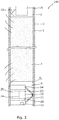
Fig. 1 shows a downhole plug andabandonment system 100 comprising a welltubular structure 1 having an inside 2 and awall 3 and being arranged in aborehole 4 of a well. The downhole plug and abandonment system further comprises afirst plug 5 arranged in the well tubular structure for sealing off alower part 6 of the well tubular structure, and asecond plug 7 arranged in the well tubular structure at a distance d and above the first plug isolating a confinedspace 8 having a space pressure Ps between the first plug and the second plug. Anabandonment device 10 is arranged in the confined space, and the abandonment device comprises aunit 11 configured to increase the space pressure, asensor 12 configured to measure a temperature and/or a pressure in the confined space, and adevice communication module 14 configured to receive an input from the sensor and to communicate signals from the abandonment device. By having an abandonment device in the confined space under the second plug, the second plug can be pressure tested from below, and thus the second plug can be tested in the circumstance which it is to prevent, namely preventing a blowout from below the plug. - After the
second plug 7 is set, theunit 11 increases the pressure or the temperature (and thereby the pressure), and thesensor 12 measures the pressure and/or the temperature to detect if the confinedspace 8 maintains the pressure before a natural decrease due to transmission of heat from the confined space to its surroundings over time. In this way, the second plug is pressure tested from below, but thefirst plug 5 is also tested from above. Once thesensor 12 has detected the pressure or temperature, the communication module sends the measured data to some device above the second plug or just sends a signal as a representation of the measured temperature or pressure. - In
Fig. 2 , the downhole plug andabandonment system 100 further comprises adownhole tool 15 arranged in the welltubular structure 1 above thesecond plug 7, and the downhole tool comprises atool communication module 16 for receiving at least one signal from theabandonment device 10. The signal may be a signal that a pressure increase has occurred in the confinedspace 8, i.e. that the unit of theabandonment device 10 has increased the pressure. Thedownhole tool 15 comprises a pressure sensor and/or atemperature sensor 20, and by measuring the pressure or temperature above thesecond plug 7 during the pressure increase in the confined space, a leak can be detected by thesensor 20 or a significant seal of the plug can be verified by thesensor 20. Thus, thesensor 12 of theabandonment device 10 measures the temperature/pressure of the fluid in the confined space to verify that a pressure increase has occurred, and thecommunication module 14 communicates to thetool 15 that a pressure increase has occurred. Thesensor 20 of thetool 15 measures the temperature/pressure just above thesecond plug 7 during the time period of the pressure increase in the confined space, and if no temperature/pressure increase is measured by thetool sensor 20, then the first and second plugs provide a seal which is sufficient for abandoning the well or drilling the well in another direction above the second plug. - As can be seen, the
downhole tool 15 is a wireline tool, and the verification data or measured data can be communicated to surface or the top of the well through the wireline. The downhole tool is therefore configured to communicate with a control unit (not shown) at surface or at the top of the well. The communication modules may send or receive data or signals by means of electromagnetic radiation or acoustic or mechanical vibrations. In one embodiment, the communication module(s) comprises/comprise a transducer and the transducer may be a piezoelectric element sending and/or receiving mechanical vibrations through the well tubular structure or through its surroundings. - In
Fig. 3 , thecommunication module 16 of thedownhole tool 15 and thecommunication module 14 of theabandonment device 10 abut the wall of the well tubular structure and transmit signals there between by means of acoustic or mechanical vibrations. - In
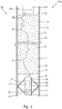
Fig. 1 , thefirst plug 5 and thesecond plug 7 are arranged in the same well tubular structure and the plugs are primarily of cement. InFig. 4 , the cement comprisessensor units 31 providing a mesh network 30 (indicated by the arrows), which may be a self-healing mesh network. In this way, the downhole tool and theabandonment device 10 are able to communicate "through" the cement via thesensor units 31 of themesh network 30. - In order to increase the pressure in the confined
space 8, the unit comprises aheating element 17, as shown inFig. 1 , for increasing the temperature in the confined space and thus increasing the pressure. The heating element may be a heater, such as an electrical heating element. InFig. 2 , the unit comprises apower charge 18 for increasing the temperature in the confinedspace 8 and thus increasing the pressure in the confined space. The power charge also increases the pressure as the solid is transformed into gas. The power charge may be a slow burning charge or similar charge providing a combustion reaction. The power charge may be a composition which when mixed provides a chemical reaction or decomposition. The power charge may thus be configured to generate a gas pressure and/or heat. InFig. 4 , the unit comprises agas canister 19 having a gas for increasing the pressure in the confined space when the gas is released in the confined space. As can be seen inFig. 3 , the unit comprises apump 23 and amotor 24 for driving the pump. The unit further comprises afluid reservoir 25 having a fluid, e.g. an accumulator. In order to power the unit and other parts of the abandonment device, the abandonment device comprises apower pack 26, such as a battery. Theabandonment device 10 may also comprise atimer 27, as shown inFig. 4 , so that the abandonment device does not need a signal to activate the unit to increase the pressure in the confined space but instead is activated after a certain elapsed time controlled by the timer. - In
Fig. 4 , theabandonment device 10 comprises avolume determination arrangement 22 configured to measure characteristics of the confinedspace 8 for determining a volume of the confined space. If the plugs are set in a more imprecise manner, thevolume determination arrangement 22 is used to determine the volume of the confined space which may be used to give a more precise determination of the pressure in the confined space during the increase of the pressure. - Each
sensor unit 31 is positioned arbitrarily in the flowable cement during the making of the plugs, and the distribution ofsensor units 31 is thus random, though distributed into the cement in an evenly manner so that thesensor units 31 are more or less evenly distributed in the flowable cement, as shown inFig. 4 . It should be noted that only some of thesensor units 31 have been assigned the reference numeral "31" inFig. 4 ; however, all circular elements shown in this figure represents asensor unit 31. - As will be explained in the following, this is realised by configuring the
sensor units 31 to establish a physically distributed independent and localised sensing network, preferably with peer-to-peer communication architecture. As will be understood from the following description, the mesh network being established by thesensor units 31 as a self-healing mesh network will automatically provide for a reliable and self-healing data path even though at least some of thesensor units 31 are out of range from the final destination, i.e. the data collection provided at the surface level. Allsensor units 31 are preferably identical, although provided with a unique ID. As shown inFig. 5 , eachsensor unit 31 is provided with a number of components configured to provide various functionality to thesensor unit 31. Eachsensor unit 31 includes apower supply 41, adigital processing unit 42, atransceiver 43, atransducer 44, and optionally asensor module 45 comprising additional sensors. Thesensor module 45 may e.g. comprise a temperature sensor and/or a pressure sensor. Thetransducer 44, together with thedigital processing unit 42, form adetector 46 for determining cement characteristics. In particular, the cement characteristics include acoustic impedance, whereby it is possible to determine the cement integrity by analysing the acoustic impedance and thus determine if the cement plug is performed in a satisfactory manner without any pockets without cement. Thedetector 46 can for example be used together with thedigital processing unit 42 to form a detecting unit for determining position data of thesensor unit 31. - The
power supply 41 is configured to supply power to the other components 42-45 of thesensor unit 31, either by means of an internal power storage, such as one or more batteries, or by converting energy of the surrounding cement to electrical energy. Thedigital processing unit 42 comprises asignal conditioning module 47, adata processing module 48, adata storage module 49 and amicro controller 50. Thedigital processing unit 42 is configured to control operation of theentire sensor unit 31, as well as temporarily storing sensed data in the memory of thedata storage module 49. Thetransceiver 43 is configured to provide wireless communcation with transceivers ofadjacent sensor units 31. For this, thetransceiver 43 comprises a radio communication module and an antenna. The radio communication module may be configured to communicate according to well-established radio protocols, e.g. IEEE 801.1aq (Shortest Path Bridging), IEEE 802.15.4 (ZigBee) etc. Thetransducer 44 is configured to transmit and receive sonar signals/pulses in order to determine characteristics of the surrounding cement. - In
Fig. 4 , theabandonment device 10 comprises an anchoringarrangement 21 configured to anchor theabandonment device 10 to the wall of the welltubular structure 1 between thefirst plug 5 and thesecond plug 7. The anchoring arrangement may have any kind of configuration capable of anchoring theabandonment device 10. - The present invention also relates to a downhole plug and abandonment method. According to this method, a
first plug 5 is arranged in a welltubular structure 1 for sealing off alower part 6 of the welltubular structure 1. Then anabandonment device 10 is arranged above the first plug, and asecond plug 7 is arranged in the well tubular structure at a distance and above the first plug isolating a confinedspace 8 having a space pressure between the first plug and the second plug, the abandonment device being arranged in the confined space. Subsequently, the pressure in the confined area is increased by means of the abandonment device, and a temperature and/or a pressure of the confined area are/is measured. At least a signal representing the measurement and/or the measurement is communicated to above the second plug. - Furthermore, in the downhole plug and abandonment method, a
downhole tool 15 may be arranged above thesecond plug 7 configured to receive the signal representing the measurement and/or the measurement. Moreover, the signal representing the measurement and/or the measurement is received by means of atool communication module 16 of the downhole tool from the abandonment device by means of a mesh network in the second plug. Further in this method, the signal representing the measurement and/or the measurement may be received by means of a tool communication module of the downhole tool from theabandonment device 10 by means of electromagnetic radiation or acoustic or mechanical vibrations. - By fluid or well fluid is meant any kind of fluid that may be present in oil or gas wells downhole, such as natural gas, oil, oil mud, crude oil, water, etc. By gas is meant any kind of gas composition present in a well, completion, or open hole, and by oil is meant any kind of oil composition, such as crude oil, an oil-containing fluid, etc. Gas, oil, and water fluids may thus all comprise other elements or substances than gas, oil, and/or water, respectively.
- By a casing or well tubular structure is meant any kind of pipe, tubing, tubular, liner, string etc. used downhole in relation to oil or natural gas production.
- In the event that the tool is not submergible all the way into the casing, a downhole tractor can be used to push the tool all the way into position in the well. The downhole tractor may have projectable arms having wheels, wherein the wheels contact the inner surface of the casing for propelling the tractor and the tool forward in the casing. A downhole tractor is any kind of driving tool capable of pushing or pulling tools in a well downhole, such as a Well Tractor®.
- Although the invention has been described in the above in connection with preferred embodiments of the invention, it will be evident for a person skilled in the art that several modifications are conceivable without departing from the invention as defined by the following claims.
Claims (15)
- A downhole plug and abandonment system (100) comprising:- a well tubular structure (1) having an inside (2) and a wall (3) and being arranged in a borehole (4),- a first plug (5) arranged in the well tubular structure for sealing off a lower part (6) of the well tubular structure,- a second plug (7) arranged in the well tubular structure at a distance (d) and above the first plug isolating a confined space (8) having a space pressure (Ps) between the first plug and the second plug,wherein an abandonment device (10) is arranged in the confined space, the abandonment device comprising:- a unit (11) configured to increase the space pressure,- a sensor (12) configured to measure a temperature and/or a pressure in the confined space, and- a device communication module (14) configured to receive an input from the sensor and to communicate signals from the abandonment device.
- A downhole plug and abandonment system according to claim 1, further comprising a downhole tool (15) arranged in the well tubular structure above the second plug, the downhole tool comprising a tool communication module (16) for receiving signals from the abandonment device.
- A downhole plug and abandonment system according to claim 1 or 2, wherein the downhole tool comprises a tool sensor (20), such as a pressure sensor and/or a temperature sensor.
- A downhole plug and abandonment system according to any of the preceding claims, wherein the unit comprises a heating element (17).
- A downhole plug and abandonment system according to any of the preceding claims, wherein the unit comprises a power charge (18).
- A downhole plug and abandonment system according to any of the preceding claims, wherein the unit comprises a gas canister (19) having a gas.
- A downhole plug and abandonment system according to any of the preceding claims, wherein the abandonment device comprises a volume determination arrangement configured to measure characteristics of the confined space for determining a volume of the confined space.
- A downhole plug and abandonment system according to any of the preceding claims, wherein the first plug and the second plug are made of cement.
- A downhole plug and abandonment system according to claim 8, wherein the cement comprises a plurality of sensor units (31) configured to form a mesh network (30).
- A downhole plug and abandonment system according to claim 9, wherein at least a plurality of the plurality of sensor units are provided with a detector (46) for detecting cement characteristics of the cement.
- A downhole plug and abandonment system according to any of the preceding claims, wherein the abandonment device comprises an anchoring arrangement (21) configured to anchor the abandonment device to the wall of the well tubular structure between the first plug and the second plug.
- A downhole plug and abandonment method comprising:- arranging a first plug (5) in a well tubular structure (1) for sealing off a lower part (6) of the well tubular structure,- arranging an abandonment device (10) above the first plug,- arranging a second plug (7) in the well tubular structure at a distance (d) and above the first plug isolating a confined space (8) having a space pressure (Ps) between the first plug and the second plug, the abandonment device being arranged in the confined space,- increasing the pressure in the confined area by means of the abandonment device,- measuring a temperature and/or a pressure of the confined area, and- communicating at least a signal representing the measurement and/or the measurement to above the second plug.
- A downhole plug and abandonment method according to claim 12, further comprising:- arranging a downhole tool above the second plug configured to receive the signal representing the measurement and/or the measurement.
- A downhole plug and abandonment method according to claim 12 or 13, further comprising:- receiving the signal representing the measurement and/or the measurement by means of a tool communication module of the downhole tool from the abandonment device by means of a mesh network in the second plug.
- A downhole plug and abandonment method according to claim 12 or 13, further comprising receiving the signal representing the measurement and/or the measurement by means of a tool communication module of the downhole tool from the abandonment device by means of electromagnetic radiation or acoustic or mechanical vibrations.
Priority Applications (10)
| Application Number | Priority Date | Filing Date | Title |
|---|---|---|---|
| EP17162047.9A EP3379021A1 (en) | 2017-03-21 | 2017-03-21 | Downhole plug and abandonment system |
| MX2019010501A MX2019010501A (en) | 2017-03-21 | 2018-03-20 | Downhole plug and abandonment system. |
| AU2018240337A AU2018240337B2 (en) | 2017-03-21 | 2018-03-20 | Downhole plug and abandonment system |
| CN201880017476.2A CN110392768A (en) | 2017-03-21 | 2018-03-20 | Underground blocking and discarding system |
| CA3055674A CA3055674A1 (en) | 2017-03-21 | 2018-03-20 | Downhole plug and abandonment system |
| PCT/EP2018/056942 WO2018172314A1 (en) | 2017-03-21 | 2018-03-20 | Downhole plug and abandonment system |
| EP18712575.2A EP3601719A1 (en) | 2017-03-21 | 2018-03-20 | Downhole plug and abandonment system |
| US15/925,917 US11286768B2 (en) | 2017-03-21 | 2018-03-20 | Downhole plug and abandonment system |
| BR112019018406-6A BR112019018406B1 (en) | 2017-03-21 | 2018-03-20 | ABANDONMENT SYSTEM AND METHOD AND DOWN WELL PLUG |
| RU2019131554A RU2770211C2 (en) | 2017-03-21 | 2018-03-20 | System for plugging and abandoning a borehole |
Applications Claiming Priority (1)
| Application Number | Priority Date | Filing Date | Title |
|---|---|---|---|
| EP17162047.9A EP3379021A1 (en) | 2017-03-21 | 2017-03-21 | Downhole plug and abandonment system |
Publications (1)
| Publication Number | Publication Date |
|---|---|
| EP3379021A1 true EP3379021A1 (en) | 2018-09-26 |
Family
ID=58398091
Family Applications (2)
| Application Number | Title | Priority Date | Filing Date |
|---|---|---|---|
| EP17162047.9A Withdrawn EP3379021A1 (en) | 2017-03-21 | 2017-03-21 | Downhole plug and abandonment system |
| EP18712575.2A Pending EP3601719A1 (en) | 2017-03-21 | 2018-03-20 | Downhole plug and abandonment system |
Family Applications After (1)
| Application Number | Title | Priority Date | Filing Date |
|---|---|---|---|
| EP18712575.2A Pending EP3601719A1 (en) | 2017-03-21 | 2018-03-20 | Downhole plug and abandonment system |
Country Status (9)
| Country | Link |
|---|---|
| US (1) | US11286768B2 (en) |
| EP (2) | EP3379021A1 (en) |
| CN (1) | CN110392768A (en) |
| AU (1) | AU2018240337B2 (en) |
| BR (1) | BR112019018406B1 (en) |
| CA (1) | CA3055674A1 (en) |
| MX (1) | MX2019010501A (en) |
| RU (1) | RU2770211C2 (en) |
| WO (1) | WO2018172314A1 (en) |
Families Citing this family (10)
| Publication number | Priority date | Publication date | Assignee | Title |
|---|---|---|---|---|
| NO342376B1 (en) * | 2015-06-09 | 2018-05-14 | Wellguard As | Apparatus for detecting fluid leakage, and related methods |
| EP3379025A1 (en) * | 2017-03-21 | 2018-09-26 | Welltec A/S | Downhole completion system |
| EP4151832A1 (en) * | 2017-03-31 | 2023-03-22 | Metrol Technology Ltd | Monitoring well installations |
| US11808093B2 (en) | 2018-07-17 | 2023-11-07 | DynaEnergetics Europe GmbH | Oriented perforating system |
| US11578549B2 (en) | 2019-05-14 | 2023-02-14 | DynaEnergetics Europe GmbH | Single use setting tool for actuating a tool in a wellbore |
| US11255147B2 (en) | 2019-05-14 | 2022-02-22 | DynaEnergetics Europe GmbH | Single use setting tool for actuating a tool in a wellbore |
| US10927627B2 (en) | 2019-05-14 | 2021-02-23 | DynaEnergetics Europe GmbH | Single use setting tool for actuating a tool in a wellbore |
| US11204224B2 (en) | 2019-05-29 | 2021-12-21 | DynaEnergetics Europe GmbH | Reverse burn power charge for a wellbore tool |
| US11946728B2 (en) | 2019-12-10 | 2024-04-02 | DynaEnergetics Europe GmbH | Initiator head with circuit board |
| US11753889B1 (en) | 2022-07-13 | 2023-09-12 | DynaEnergetics Europe GmbH | Gas driven wireline release tool |
Citations (4)
| Publication number | Priority date | Publication date | Assignee | Title |
|---|---|---|---|---|
| WO1999060250A1 (en) * | 1998-05-04 | 1999-11-25 | Subsurface Technology As | Method for installing a sensor in connection with plugging a well |
| EP2599955A1 (en) * | 2011-11-30 | 2013-06-05 | Welltec A/S | Pressure integrity testing system |
| US20130299165A1 (en) * | 2012-05-10 | 2013-11-14 | Bp Corporation North America Inc. | Methods and systems for long-term monitoring of a well system during abandonment |
| US20140034301A1 (en) * | 2012-07-31 | 2014-02-06 | Hallliburton Energy Services, Inc. | Cementing Plug Tracking Using Distributed Strain Sensing |
Family Cites Families (20)
| Publication number | Priority date | Publication date | Assignee | Title |
|---|---|---|---|---|
| SU1710699A1 (en) * | 1990-01-31 | 1992-02-07 | Всесоюзный научно-исследовательский институт горной геомеханики и маркшейдерского дела | Drill hole plugging-back method |
| US6538576B1 (en) * | 1999-04-23 | 2003-03-25 | Halliburton Energy Services, Inc. | Self-contained downhole sensor and method of placing and interrogating same |
| US6443228B1 (en) * | 1999-05-28 | 2002-09-03 | Baker Hughes Incorporated | Method of utilizing flowable devices in wellbores |
| JP4188087B2 (en) * | 2001-03-23 | 2008-11-26 | シュルンベルジェ ホールディングス リミテッド | Fluid characteristic sensor |
| CN1548700A (en) * | 2003-05-13 | 2004-11-24 | 军 金 | Plugging technology of high infiltration layer |
| RU2283942C2 (en) * | 2004-12-03 | 2006-09-20 | Закрытое акционерное общество "Октопус" | Well killing method |
| US8291975B2 (en) * | 2007-04-02 | 2012-10-23 | Halliburton Energy Services Inc. | Use of micro-electro-mechanical systems (MEMS) in well treatments |
| WO2009089416A2 (en) * | 2008-01-11 | 2009-07-16 | Services Petroliers Schlumberger | Zonal testing with the use of coiled tubing |
| EP2157279A1 (en) | 2008-08-22 | 2010-02-24 | Schlumberger Holdings Limited | Transmitter and receiver synchronisation for wireless telemetry systems technical field |
| US8397741B2 (en) * | 2009-06-10 | 2013-03-19 | Baker Hughes Incorporated | Delay activated valve and method |
| US9091791B2 (en) * | 2012-05-11 | 2015-07-28 | Baker Hughes Incorporated | Accounting for bending effect in deep azimuthal resistivity measurements using inversion |
| US9983276B2 (en) * | 2012-06-25 | 2018-05-29 | Halliburton Energy Services, Inc. | Downhole all-optical magnetometer sensor |
| US20130133883A1 (en) * | 2012-08-16 | 2013-05-30 | Tejas Research And Engineering, Llc | Dual downhole pressure barrier with communication to verify |
| RU138328U1 (en) * | 2013-10-08 | 2014-03-10 | Юлий Андреевич Гуторов | DEVICE FOR LIQUIDATION OF LOCAL DEFECTS IN A CEMENT RING OF A CASING |
| US9163497B2 (en) * | 2013-10-22 | 2015-10-20 | Sas Institute Inc. | Fluid flow back prediction |
| US9845655B2 (en) * | 2015-10-01 | 2017-12-19 | Cameron International Corporation | System and method for testing an insert packer assembly |
| US20180305993A1 (en) * | 2015-12-16 | 2018-10-25 | Halliburton Energy Services, Inc. | Buoyancy control in monitoring apparatus |
| US10113410B2 (en) * | 2016-09-30 | 2018-10-30 | Onesubsea Ip Uk Limited | Systems and methods for wirelessly monitoring well integrity |
| GB2553155B (en) | 2016-10-25 | 2019-10-02 | Expro North Sea Ltd | A communication system utilising a metallic well structure. |
| NO342925B1 (en) * | 2016-12-06 | 2018-09-03 | Well Set P A As | System and method for testing a barrier in a well from below |
-
2017
- 2017-03-21 EP EP17162047.9A patent/EP3379021A1/en not_active Withdrawn
-
2018
- 2018-03-20 RU RU2019131554A patent/RU2770211C2/en active
- 2018-03-20 EP EP18712575.2A patent/EP3601719A1/en active Pending
- 2018-03-20 AU AU2018240337A patent/AU2018240337B2/en active Active
- 2018-03-20 WO PCT/EP2018/056942 patent/WO2018172314A1/en unknown
- 2018-03-20 CA CA3055674A patent/CA3055674A1/en not_active Abandoned
- 2018-03-20 CN CN201880017476.2A patent/CN110392768A/en active Pending
- 2018-03-20 MX MX2019010501A patent/MX2019010501A/en unknown
- 2018-03-20 US US15/925,917 patent/US11286768B2/en active Active
- 2018-03-20 BR BR112019018406-6A patent/BR112019018406B1/en active IP Right Grant
Patent Citations (4)
| Publication number | Priority date | Publication date | Assignee | Title |
|---|---|---|---|---|
| WO1999060250A1 (en) * | 1998-05-04 | 1999-11-25 | Subsurface Technology As | Method for installing a sensor in connection with plugging a well |
| EP2599955A1 (en) * | 2011-11-30 | 2013-06-05 | Welltec A/S | Pressure integrity testing system |
| US20130299165A1 (en) * | 2012-05-10 | 2013-11-14 | Bp Corporation North America Inc. | Methods and systems for long-term monitoring of a well system during abandonment |
| US20140034301A1 (en) * | 2012-07-31 | 2014-02-06 | Hallliburton Energy Services, Inc. | Cementing Plug Tracking Using Distributed Strain Sensing |
Also Published As
| Publication number | Publication date |
|---|---|
| BR112019018406A2 (en) | 2020-04-07 |
| EP3601719A1 (en) | 2020-02-05 |
| RU2019131554A (en) | 2021-04-21 |
| AU2018240337B2 (en) | 2021-04-01 |
| BR112019018406B1 (en) | 2023-12-19 |
| CN110392768A (en) | 2019-10-29 |
| US11286768B2 (en) | 2022-03-29 |
| RU2770211C2 (en) | 2022-04-14 |
| US20180274356A1 (en) | 2018-09-27 |
| RU2019131554A3 (en) | 2021-07-19 |
| CA3055674A1 (en) | 2018-09-27 |
| WO2018172314A1 (en) | 2018-09-27 |
| MX2019010501A (en) | 2019-10-15 |
| AU2018240337A1 (en) | 2019-10-31 |
Similar Documents
| Publication | Publication Date | Title |
|---|---|---|
| AU2018240337B2 (en) | Downhole plug and abandonment system | |
| US10400542B2 (en) | Downhole completion system | |
| US9797218B2 (en) | Wellbore systems with hydrocarbon leak detection apparatus and methods | |
| BRPI0905283A2 (en) | method for checking the status of a drill gun, method for checking the status of a drill gun system, system for checking the status of a drill gun, method for checking the environmental condition of a drill gun, and system for check the environmental condition of a drill barrel | |
| US10267144B2 (en) | Downhole sensor system | |
| EP3601729A1 (en) | Downhole drilling system | |
| NO324283B1 (en) | Downhole instrumented bridge plug | |
| US20180274353A1 (en) | Downhole sensor system | |
| US10774619B2 (en) | Downhole completion system | |
| EP2942475A1 (en) | Downhole annular barrier system |
Legal Events
| Date | Code | Title | Description |
|---|---|---|---|
| PUAI | Public reference made under article 153(3) epc to a published international application that has entered the european phase |
Free format text: ORIGINAL CODE: 0009012 |
|
| AK | Designated contracting states |
Kind code of ref document: A1 Designated state(s): AL AT BE BG CH CY CZ DE DK EE ES FI FR GB GR HR HU IE IS IT LI LT LU LV MC MK MT NL NO PL PT RO RS SE SI SK SM TR |
|
| AX | Request for extension of the european patent |
Extension state: BA ME |
|
| STAA | Information on the status of an ep patent application or granted ep patent |
Free format text: STATUS: THE APPLICATION IS DEEMED TO BE WITHDRAWN |
|
| 18D | Application deemed to be withdrawn |
Effective date: 20190327 |