EP3378598A1 - Method for operating a fastener driving device - Google Patents
Method for operating a fastener driving device Download PDFInfo
- Publication number
- EP3378598A1 EP3378598A1 EP17161823.4A EP17161823A EP3378598A1 EP 3378598 A1 EP3378598 A1 EP 3378598A1 EP 17161823 A EP17161823 A EP 17161823A EP 3378598 A1 EP3378598 A1 EP 3378598A1
- Authority
- EP
- European Patent Office
- Prior art keywords
- drive
- driving
- motor
- magazine
- channel
- Prior art date
- Legal status (The legal status is an assumption and is not a legal conclusion. Google has not performed a legal analysis and makes no representation as to the accuracy of the status listed.)
- Withdrawn
Links
Images


Classifications
-
- B—PERFORMING OPERATIONS; TRANSPORTING
- B25—HAND TOOLS; PORTABLE POWER-DRIVEN TOOLS; MANIPULATORS
- B25C—HAND-HELD NAILING OR STAPLING TOOLS; MANUALLY OPERATED PORTABLE STAPLING TOOLS
- B25C1/00—Hand-held nailing tools; Nail feeding devices
-
- B—PERFORMING OPERATIONS; TRANSPORTING
- B25—HAND TOOLS; PORTABLE POWER-DRIVEN TOOLS; MANIPULATORS
- B25C—HAND-HELD NAILING OR STAPLING TOOLS; MANUALLY OPERATED PORTABLE STAPLING TOOLS
- B25C1/00—Hand-held nailing tools; Nail feeding devices
- B25C1/06—Hand-held nailing tools; Nail feeding devices operated by electric power
-
- B—PERFORMING OPERATIONS; TRANSPORTING
- B25—HAND TOOLS; PORTABLE POWER-DRIVEN TOOLS; MANIPULATORS
- B25C—HAND-HELD NAILING OR STAPLING TOOLS; MANUALLY OPERATED PORTABLE STAPLING TOOLS
- B25C1/00—Hand-held nailing tools; Nail feeding devices
- B25C1/008—Safety devices
Definitions
- the application relates to a method for operating a fastener driving-in device.
- Such devices usually have a drive-in element for driving in a fastening element arranged in a drive-in fastening element and a drive device for the drive-in element.
- the fasteners are transported by means of a transport device successively in the drive-in channel.
- the user will first attempt to perform a drive-in operation and reload further fasteners only after recognizing the empty magazine. It is therefore desirable to operate a driving device so that the time consumed for such unsuccessful attempt at driving is reduced.
- the object is achieved in a method for operating a fastener driving-in device with a drive-in channel, a drive-in element which is intended to drive a fastening element arranged in the drive-in channel into a substrate, a drive device which is provided for this purpose Driving drive element on the arranged in the drive-in fastener, wherein the drive device comprises a motor, a magazine for fasteners, a transport device, which is intended to transport existing in the magazine fasteners successively in the drive-in channel, and a detection device for querying whether and / or how many fasteners are present in the magazine, achieved by operating the motor according to a standard pattern, when the detection device detects a predetermined minimum number of fasteners in the magazine, and that the motor operates according to a specific pattern other than the standard pattern is when the detection device detects no fasteners or a predetermined minimum number below the number of fasteners in the magazine.
- a user of the driver immediately recognizes that the fasteners have been used up immediately or after the next drive and the magazine is to be filled.
- the user recognizes this preferably acoustically and / or haptically.
- the special pattern differs from the standard pattern by a time interval since an event triggering the operation of the motor.
- the event triggering the operation of the motor is preferably completion of a drive-in operation of the drive-in device, activation of the drive-in device or lifting of the drive-in device from a substrate.
- the special pattern differs from the standard pattern by a time duration of operating the motor, by a speed of the motor and / or by a different sequence of individual operating phases with different time intervals and / or different duration and / or different speed of the motor.
- the driving-in device comprises a pressing device for querying whether the working device is pressed against a substrate, wherein the pressing device is in a contact pressure position when the working device is pressed against a substrate.
- the pressing device allows the driving of the driving element to the fastening element to only in the Anpress too.
- the engine is operated to the drive device in a eintreibren state, from which the driving element is driven to the fastener to.
- the drive-in device preferably comprises a mechanical energy store, wherein the motor is operated in order to charge the mechanical energy store.
- the motor is operated to drive the driving element on the fastener.
- the motor is an electric motor which is supplied with electrical energy from an electrochemical energy store.
- the detection device detects the presence of a fastener at a predetermined location in the magazine or the drive-in channel.
- the transport device has a slide for the fastening elements in the magazine, wherein the detection device detects a position of the slider.
- the detection device performs the query whether and / or how many fasteners are present in the magazine, capacitive, inductive, magnetic, optical, acoustic or electromechanical.
- Fig. 1 shows a schematic view of a driving-in device 10.
- the driving-in device 10 comprises a housing 20 in which a driving element 100 designed as a piston and a drive device for the driving element 100 are received.
- the drive device comprises a clutch device 150 held closed by a holding element designed as a pawl 800, a spring 200 with a front spring element 210 and a rear spring element 220, a roller train 260 with a force deflector designed as a belt 270, a front roller holder 281 and a rear roller holder 282 , a spindle drive 300 with a spindle 310 and a spindle nut 320, a gear 400, a motor 480 and a control device 500.
- the driving-in device 10 furthermore has a driving-in channel 700 for the fastening elements and a pressing device 750.
- the pressing device allows the driving of the driving element 100 to the fastener to only in the Anpress ein.
- the driving-in device 10 comprises a magazine 40 for fastening elements and a transport device which is provided for transporting fastening elements present in the magazine 40 successively into the driving-in channel 700.
- the housing 20 has a handle 30 on which a manual switch 35 is arranged.
- the control device 500 communicates with the manual switch 35 as well as with a plurality of sensors 990, 992, 994, 996, 998, 1000 in order to detect the operating state of the driving-in device 10.
- the sensors 990, 992, 994, 996, 998, 1000 each have a Hall probe, which detects the movement of a magnet armature, not shown, which is arranged on the respectively to be detected element, in particular fixed.
- a movement of the pressing device 750 is detected forward, thereby indicating that the guide channel 700 has been removed from the driving-in device 10.
- Anpresssensor 992 a movement of the pressing device 750 is detected to the rear, thereby indicating that the driving device 10 is pressed against a substrate.
- the roller holder sensor a movement of the front roller holder 281 is detected, indicating whether the spring 200 is tensioned.
- the pawl sensor 996 a movement of the pawl 800 is detected, thereby indicating whether the clutch device 150 is held in its closed state.
- the spindle sensor 998 detects whether the spindle nut 320 or a return rod attached to the spindle nut 320 is in its rearmost position.
- a trained as a slide sensor detection device 1000 is finally detected whether a arranged in the magazine 40 slide in his in Fig. 1 is uppermost position, in which no fasteners are arranged in the magazine.
- the driving element 100 After using the Eintreibiatas 100 a fastener to the front, that is, in the drawing to the left, was driven into a ground, the driving element 100 is in its Eintreibposition.
- the front spring element 210 and the rear spring element 220 are in the relaxed state, in which they still have some residual stress.
- the front roller holder 281 is in its forwardmost position in operation and the rear roller holder 282 is in its rearmost position in operation.
- the spindle nut 320 is located at the front end of the spindle 310. Due to the possibly relaxed to a residual stress spring elements 210, 220, the band 270 is substantially free of load.
- the control device 500 As soon as the control device 500 has detected by means of a sensor that the driving element 100 is in its setting position, the control device 500 causes a return operation, in which the driving element 100 is conveyed to its starting position.
- the motor 480 rotates via the gear 400, the spindle 310 in a first rotational direction, so that the rotationally secured spindle nut 320 is moved backwards.
- the return rods engage in the vomholzapfen the drive-in element 100 and thus convey the drive-in element 100 also to the rear.
- the driving element 100 takes along the tape 270, whereby the spring elements 210, 220 are not tensioned, since the spindle nut 320 also takes the tape 270 backwards and releases over the rollers of the rear roller holder 282 as much tape length as the piston between them Feeding roles of the front roller holder 281.
- the tape 270 thus remains substantially free of load during the return operation.
- the driving element 100 is then in its starting position and is engaged with its coupling plug part in the coupling device 150.
- the front spring member 210 and the rear spring member 220 are still in their respective relaxed state, the front roll holder 281 is in its forwardmost position and the rear roll holder 282 is in its rearmost position.
- the spindle nut 320 is located at the rear end of the spindle 310. Due to the relaxed spring elements 210, 220, the band 270 is still substantially free of load.
- the control device 500 causes a tensioning process in which the spring elements 210, 220 are tensioned.
- the motor rotates via the gear 400, the spindle 310 in a direction opposite to the first direction of rotation second rotational direction, so that the rotationally secured spindle nut 320 is moved forward.
- the coupling device 150 holds the coupling male part of the driving-in element 100 fixed so that the length of the strip, which is drawn in by the spindle nut 320 between the rear rollers, can not be released by the piston.
- the roller holders 281, 282 are therefore moved towards each other and the spring elements 210, 220 are tensioned.
- the driving element 100 is then still in its initial position and is engaged with its coupling male part in the coupling device 150.
- the front spring member 210 and the rear spring member 220 are cocked, the front roller holder 281 is in its rearmost position, and the rear roller holder 282 is in its foremost position.
- the spindle nut 320 is located at the front end of the spindle 310.
- the belt 270 deflects the biasing force of the spring elements 210, 220 on the rollers of the roller holders 281, 282 and transmits the clamping force to the driving element 100, which is held against the clamping force by the coupling device 150 becomes.
- the drive-in device is now ready for a drive-in process. As soon as a user pulls the trigger 34, the coupling device 150 releases the driving element 100, which then transfers the clamping energy of the spring elements 210, 220 to a fastening element and drives the fastening element into the ground.
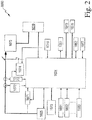
- Fig. 2 shows a control structure of the drive-in simplified.
- the control device 1024 is indicated.
- the switching and / or sensor devices 1031 to 1033 provide, as indicated by arrows, information or signals to the control device 1024.
- a manual or main switch 1070 of the driving device is in communication with the control device 1024.
- the controller 1024 communicates with the battery 1025.
- a rectangle is a latching 1071 indicated.
- a voltage measurement and a current measurement are indicated.
- Another rectangle 1074 is a shutdown indicated.
- a B6 bridge 1075 is indicated.
- This is a 6-pulse bridge circuit with semiconductor elements for controlling the electric drive motor 1020.
- This is preferably driven by driver blocks which in turn are preferably controlled by a controller.
- Such integrated driver components have, in addition to the appropriate driving the bridge crizs still the advantage that they bring the switching elements of the B6 bridge in a defined state when undervoltage occurs.
- a temperature sensor is indicated, which communicates with the shutdown 1074 and the controller 1024.
- a further arrow indicates that the control device 1024 outputs information to the display 1051.
- the control device 1024 communicates with the interface 1052 and with another service interface 1077.
- a parking brake is indicated, which is controlled by the control device 1024.
- the parking brake 1078 is used to slow down movements when relaxing the energy storage 1010 and / or to keep the energy storage in the tensioned or charged state.
- the parking brake 1078 can cooperate for this purpose, for example, with a belt drive, not shown, or gear.
- Another rectangle 1079 indicates a detection device for querying whether and / or how many fastening elements are present in the magazine.
- the controller 1024 operates the motor according to a standard pattern to transfer the drive device to its ready-to-drive state. For example, immediately after a lifting of the drive-in device from a substrate after a drive-in process, the engine is started to operate.
- the controller 1024 operates the motor in a specific pattern other than the standard pattern. For example, after lifting the drive-in device from a substrate after a drive-in operation, it is only with delay that the engine starts to operate. Alternatively, the engine is after lifting the Drive from a substrate after a drive operation initially operated with increased or decreased speed.
- Fig. 3 shows a section of a driving device 410 according to a further embodiment.
- the drive-in device comprises a magazine 440 and a transport device with a slide 420 for transporting fastening elements 430 in the magazine 440 in a transport direction 425 and a spring element 450, which is designed as a scroll spring and the slider 420 and thus the fastening elements 430 to a not shown Driving channel of the driving device 410 applied to a force.
- the driving-in device 410 comprises a detection device 460, which detects a position of the slider 420.
- the detection device 460 comprises an electrical switch 470, which is closed by an actuating element 480 of the slider 420 when the slider 420 at its in Fig. 3 reached the top position. This is preferably the case when the last fastening element present in the magazine 440 is transported into the drive-in channel.
- the detection device performs the query whether and / or how many fasteners are present in the magazine, capacitive, inductive, magnetic, optical, acoustic or electromechanical.
- gaseous, powdered, pneumatically, hydraulically or electromagnetically operated driving devices can be realized in which a drive device has a combustion-powered, pneumatically operated, hydraulically operated or also electrically operated motor, which is operated in accordance with the invention, for example a drive-in element after one Drive back to a home position or drive a fan.
- the invention can be used in a screwdriver, in particular cordless screwdriver.
Landscapes
- Engineering & Computer Science (AREA)
- Mechanical Engineering (AREA)
- Portable Nailing Machines And Staplers (AREA)
- Details Of Spanners, Wrenches, And Screw Drivers And Accessories (AREA)
Abstract
Verfahren zum Betreiben einer Eintreibvorrichtung (10) für Befestigungselemente, bei dem ein Motor (480) nach einem speziellen Muster betrieben wird, wenn keine Befestigungselemente mehr in einem Magazin (40) der Eintreibvorrichtung (10) vorhanden sind.

Description
Die Anmeldung betrifft ein Verfahren zum Betreiben einer Eintreibvorrichtung für Befestigungselemente.The application relates to a method for operating a fastener driving-in device.
Derartige Vorrichtungen weisen üblicherweise ein Eintreibelement zum Eintreiben eines in einem Eintreibkanal angeordneten Befestigungselements sowie eine Antriebseinrichtung für das Eintreibelement auf. Bei Vorrichtungen mit einem Magazin werden die Befestigungselemente mit Hilfe einer Transporteinrichtung nacheinander in den Eintreibkanal transportiert. Wenn alle Befestigungselemente in dem Magazin verbraucht sind, ohne dass dies einem Benutzer der Eintreibvorrichtung bekannt ist, wird der Benutzer zunächst versuchen, einen Eintreibvorgang durchzuführen, und erst nach Erkennen des leeren Magazins weitere Befestigungselemente nachladen. Es ist daher wünschenswert, eine Eintreibvorrichtung so zu betreiben, dass die für solche erfolglosen Eintreibversuche verbrauchte Zeit reduziert ist.Such devices usually have a drive-in element for driving in a fastening element arranged in a drive-in fastening element and a drive device for the drive-in element. In devices with a magazine, the fasteners are transported by means of a transport device successively in the drive-in channel. When all of the fasteners in the magazine are exhausted without any knowledge of a user of the drive-in device, the user will first attempt to perform a drive-in operation and reload further fasteners only after recognizing the empty magazine. It is therefore desirable to operate a driving device so that the time consumed for such unsuccessful attempt at driving is reduced.
Die Aufgabe wird bei einem Verfahren zum Betreiben einer Eintreibvorrichtung für Befestigungselemente mit einem Eintreibkanal, einem Eintreibelement, welches dafür vorgesehen ist, ein in dem Eintreibkanal angeordnetes Befestigungselement in einen Untergrund einzutreiben, einer Antriebsvorrichtung, welche dafür vorgesehen ist, das Eintreibelement auf das in dem Eintreibkanal angeordnete Befestigungselement zu anzutreiben, wobei die Antriebsvorrichtung einen Motor umfasst, einem Magazin für Befestigungselemente, einer Transporteinrichtung, welche dafür vorgesehen ist, in dem Magazin vorhandene Befestigungselemente nacheinander in den Eintreibkanal zu transportieren, und einer Detektionseinrichtung zum Abfragen, ob und/oder wie viele Befestigungselemente in dem Magazin vorhanden sind, dadurch gelöst, dass der Motor nach einem Standardmuster betrieben wird, wenn die Detektionseinrichtung eine vorgegebene Mindestzahl von Befestigungselementen in dem Magazin detektiert, und dass der Motor nach einem von dem Standardmuster abweichenden speziellen Muster betrieben wird, wenn die Detektionseinrichtung keine Befestigungselemente oder eine die vorgegebene Mindestzahl unterschreitende Anzahl von Befestigungselementen in dem Magazin detektiert.The object is achieved in a method for operating a fastener driving-in device with a drive-in channel, a drive-in element which is intended to drive a fastening element arranged in the drive-in channel into a substrate, a drive device which is provided for this purpose Driving drive element on the arranged in the drive-in fastener, wherein the drive device comprises a motor, a magazine for fasteners, a transport device, which is intended to transport existing in the magazine fasteners successively in the drive-in channel, and a detection device for querying whether and / or how many fasteners are present in the magazine, achieved by operating the motor according to a standard pattern, when the detection device detects a predetermined minimum number of fasteners in the magazine, and that the motor operates according to a specific pattern other than the standard pattern is when the detection device detects no fasteners or a predetermined minimum number below the number of fasteners in the magazine.
Aufgrund der Abweichung des speziellen Musters von dem Standardmuster erkennt ein Benutzer der Eintreibvorrichtung sofort, dass die Befestigungselemente unmittelbar oder nach dem nächsten Eintreibvorgang aufgebraucht sind und das Magazin zu befüllen ist. Der Benutzer erkennt dies bevorzugt akustisch und/oder haptisch.Due to the deviation of the particular pattern from the standard pattern, a user of the driver immediately recognizes that the fasteners have been used up immediately or after the next drive and the magazine is to be filled. The user recognizes this preferably acoustically and / or haptically.
Nach einer vorteilhaften Ausgestaltung unterscheidet sich das spezielle Muster von dem Standardmuster durch einen zeitlichen Abstand seit einem das Betreiben des Motors auslösenden Ereignis. Bevorzugt ist das das Betreiben des Motors auslösende Ereignis ein Abschluss eines Eintreibvorgangs der Eintreibvorrichtung, ein Einschalten der Eintreibvorrichtung oder ein Abheben der Eintreibvorrichtung von einem Untergrund.According to an advantageous embodiment, the special pattern differs from the standard pattern by a time interval since an event triggering the operation of the motor. The event triggering the operation of the motor is preferably completion of a drive-in operation of the drive-in device, activation of the drive-in device or lifting of the drive-in device from a substrate.
Nach einer vorteilhaften Ausgestaltung unterscheidet sich das spezielle Muster von dem Standardmuster durch eine zeitliche Dauer des Betreibens des Motors, durch eine Drehzahl des Motors und/oder durch eine abweichende Abfolge von einzelnen Betriebsphasen mit unterschiedlichem zeitlichem Abstand und/oder unterschiedlicher Dauer und/oder unterschiedlicher Drehzahl des Motors.According to an advantageous embodiment, the special pattern differs from the standard pattern by a time duration of operating the motor, by a speed of the motor and / or by a different sequence of individual operating phases with different time intervals and / or different duration and / or different speed of the motor.
Nach einer vorteilhaften Ausgestaltung umfasst die Eintreibvorrichtung eine Anpresseinrichtung zum Abfragen, ob das Arbeitsgerät an einen Untergrund angepresst ist, wobei sich die Anpresseinrichtung in einer Anpressstellung befindet, wenn das Arbeitsgerät an einen Untergrund angepresst ist. Bevorzugt lässt die Anpresseinrichtung das Antreiben des Eintreibelements auf das Befestigungselement zu nur in der Anpressstellung zu.According to an advantageous embodiment, the driving-in device comprises a pressing device for querying whether the working device is pressed against a substrate, wherein the pressing device is in a contact pressure position when the working device is pressed against a substrate. Preferably, the pressing device allows the driving of the driving element to the fastening element to only in the Anpressstellung.
Nach einer vorteilhaften Ausgestaltung wird der Motor betrieben, um die Antriebseinrichtung in einen eintreibbereiten Zustand zu überführen, von dem aus das Eintreibelement auf das Befestigungselement zu angetrieben wird. Bevorzugt umfasst die Eintreibvorrichtung einen mechanischen Energiespeicher, wobei der Motor betrieben wird, um den mechanischen Energiespeicher aufzuladen.According to an advantageous embodiment of the engine is operated to the drive device in a eintreibbereiten state, from which the driving element is driven to the fastener to. The drive-in device preferably comprises a mechanical energy store, wherein the motor is operated in order to charge the mechanical energy store.
Nach einer vorteilhaften Ausgestaltung wird der Motor betrieben, um das Eintreibelement auf das Befestigungselement zu anzutreiben.According to an advantageous embodiment of the motor is operated to drive the driving element on the fastener.
Nach einer vorteilhaften Ausgestaltung ist der Motor ein Elektromotor, der mit elektrischer Energie aus einem elektrochemischen Energiespeicher versorgt wird.According to an advantageous embodiment, the motor is an electric motor which is supplied with electrical energy from an electrochemical energy store.
Nach einer vorteilhaften Ausgestaltung detektiert die Detektionseinrichtung das Vorhandensein eines Befestigungselementes an einem vorbestimmten Ort in dem Magazin oder dem Eintreibkanal.According to an advantageous embodiment, the detection device detects the presence of a fastener at a predetermined location in the magazine or the drive-in channel.
Nach einer vorteilhaften Ausgestaltung weist die Transporteinrichtung einen Schieber für die Befestigungselemente in dem Magazin auf, wobei die Detektionseinrichtung eine Position des Schiebers detektiert.According to an advantageous embodiment, the transport device has a slide for the fastening elements in the magazine, wherein the detection device detects a position of the slider.
Nach einer vorteilhaften Ausgestaltung führt die Detektionseinrichtung die Abfrage, ob und/oder wie viele Befestigungselemente in dem Magazin vorhanden sind, kapazitiv, induktiv, magnetisch, optisch, akustisch oder elektromechanisch durch.According to an advantageous embodiment, the detection device performs the query whether and / or how many fasteners are present in the magazine, capacitive, inductive, magnetic, optical, acoustic or electromechanical.
Nachfolgend werden Ausführungsformen einer Vorrichtung zum Eintreiben eines Befestigungselementes in einen Untergrund anhand von Beispielen unter Bezugnahme auf die Zeichnungen näher erläutert. Es zeigen:
- Fig. 1
- ein Aufbauschema einer Eintreibvorrichtung,
- Fig. 2
- ein Schaltdiagramm einer Eintreibvorrichtung und
- Fig. 3
- schematisch einen Ausschnitt einer Eintreibvorrichtung.
- Fig. 1
- a construction diagram of a drive-in device,
- Fig. 2
- a circuit diagram of a driving device and
- Fig. 3
- schematically a section of a driving-in device.
Die Eintreibvorrichtung 10 weist weiterhin einen Eintreibkanal 700 für die Befestigungselemente und eine Anpresseinrichtung 750 auf. Die Anpresseinrichtung lässt das Antreiben des Eintreibelements 100 auf das Befestigungselement zu nur in der Anpressstellung zu. Weiterhin umfasst die Eintreibvorrichtung 10 ein Magazin 40 für Befestigungselemente und eine Transporteinrichtung, welche dafür vorgesehen ist, in dem Magazin 40 vorhandene Befestigungselemente nacheinander in den Eintreibkanal 700 zu transportieren. Darüber hinaus weist das Gehäuse 20 einen Griff 30 auf, an welchem ein Handschalter 35 angeordnet ist. Die Steuereinrichtung 500 kommuniziert mit dem Handschalter 35 sowie mit mehreren Sensoren 990, 992, 994, 996, 998, 1000, um den Betriebszustand der Eintreibvorrichtung 10 zu erfassen. Die Sensoren 990, 992, 994, 996, 998, 1000 weisen jeweils eine Hallsonde auf, welche die Bewegung eines nicht dargestellten Magnetankers erfasst, der auf dem jeweils zu erfassenden Element angeordnet, insbesondere befestigt ist.The driving-in
Mit dem Führungskanalsensor 990 wird eine Bewegung der Anpresseinrichtung 750 nach vorne erfasst, wodurch angezeigt wird, dass der Führungskanal 700 von der Eintreibvorrichtung 10 abgenommen wurde. Mit dem Anpresssensor 992 wird eine Bewegung der Anpresseinrichtung 750 nach hinten erfasst, wodurch angezeigt wird, dass die Eintreibvorrichtung 10 an einen Untergrund angepresst ist. Mit dem Rollenhaltersensor wird eine Bewegung des vorderen Rollenhalters 281 erfasst, wodurch angezeigt wird, ob die Feder 200 gespannt ist. Mit dem Klinkensensor 996 wird eine Bewegung der Klinke 800 erfasst, wodurch angezeigt wird, ob die Kupplungseinrichtung 150 in ihrem geschlossenen Zustand gehalten ist. Mit dem Spindelsensor 998 wird erfasst, ob die Spindelmutter 320 beziehungsweise eine an der Spindelmutter 320 befestigte Rückholstange in ihrer hintersten Stellung ist. Mit einer als Schiebersensor ausgebildeten Detektionseinrichtung 1000 wird schliesslich erfasst, ob ein in dem Magazin 40 angeordneter Schieber in seiner in
Nachdem mit Hilfe des Eintreibelementes 100 ein Befestigungselement nach vorne, das heisst in der Zeichnung nach links, in einen Untergrund eingetrieben wurde, befindet sich das Eintreibelement 100 in seiner Eintreibposition. Das vordere Federelement 210 und das hintere Federelement 220 befinden sich im entspannten Zustand, in dem sie tatsächlich noch eine gewisse Restspannung aufweisen. Der vordere Rollenhalter 281 ist in seiner im Betriebsablauf vordersten Position und der hintere Rollenhalter 282 ist in seiner im Betriebsablauf hintersten Position. Die Spindelmutter 320 befindet sich am vorderen Ende der Spindel 310. Aufgrund der unter Umständen bis auf eine Restspannung entspannten Federelemente 210, 220 ist das Band 270 im Wesentlichen lastfrei.After using the Eintreibelementes 100 a fastener to the front, that is, in the drawing to the left, was driven into a ground, the
Sobald die Steuereinrichtung 500 mittels eines Sensors erkannt hat, dass das Eintreibelement 100 in seiner Setzposition ist, veranlasst die Steuereinrichtung 500 einen Rückholvorgang, bei dem das Eintreibelement 100 in seine Ausgangsposition befördert wird. Hierzu dreht der Motor 480 über das Getriebe 400 die Spindel 310 in einer ersten Drehrichtung, so dass die verdrehgesicherte Spindelmutter 320 nach hinten bewegt wird.As soon as the
Die Rückholstangen greifen dabei in den Rückholzapfen des Eintreibelementes 100 ein und befördern damit das Eintreibelement 100 ebenfalls nach hinten. Das Eintreibelement 100 nimmt dabei das Band 270 mit, wodurch die Federelemente 210, 220 jedoch nicht gespannt werden, da die Spindelmutter 320 ebenfalls das Band 270 nach hinten mitnimmt und dabei über die Rollen des hinteren Rollenhalters 282 genauso viel Bandlänge freigibt wie der Kolben zwischen den Rollen des vorderen Rollenhalters 281 einzieht. Das Band 270 bleibt also während des Rückholvorgangs im Wesentlichen lastfrei.The return rods engage in the Rückholzapfen the drive-in
Das Eintreibelement 100 befindet sich dann in seiner Ausgangsstellung und ist mit seinem Kupplungssteckteil in der Kupplungseinrichtung 150 eingekuppelt. Das vordere Federelement 210 und das hintere Federelement 220 befinden sich weiterhin in ihrem jeweiligen entspannten Zustand, der vordere Rollenhalter 281 ist in seiner vordersten Position und der hintere Rollenhalter 282 ist in seiner hintersten Position. Die Spindelmutter 320 befindet sich am hinteren Ende der Spindel 310. Aufgrund der entspannten Federelemente 210, 220 ist das Band 270 weiterhin im Wesentlichen lastfrei.The
Wird die Eintreibvorrichtung nun vom Untergrund abgehoben, so dass die Anpresseinrichtung 750 gegenüber dem Eintreibkanal 700 nach vorne verschoben wird, veranlasst die Steuereinrichtung 500 einen Spannvorgang, bei dem die Federelemente 210, 220 gespannt werden. Hierzu dreht der Motor über das Getriebe 400 die Spindel 310 in einer zur ersten Drehrichtung entgegen gesetzten zweiten Drehrichtung, so dass die verdrehgesicherte Spindelmutter 320 nach vorne bewegt wird. Die Kupplungseinrichtung 150 hält dabei das Kupplungssteckteil des Eintreibelementes 100 fest, so dass die Bandlänge, welche von der Spindelmutter 320 zwischen den hinteren Rollen eingezogen wird, nicht von dem Kolben freigegeben werden kann. Die Rollenhalter 281, 282 werden daher aufeinander zu bewegt und die Federelemente 210, 220 werden gespannt.If the driving-in device is now lifted off the ground so that the
Das Eintreibelement 100 befindet sich dann weiterhin in seiner Ausgangsstellung und ist mit seinem Kupplungssteckteil in der Kupplungseinrichtung 150 eingekuppelt. Das vordere Federelement 210 und das hintere Federelement 220 sind gespannt, der vordere Rollenhalter 281 ist in seiner hintersten Position und der hintere Rollenhalter 282 ist in seiner vordersten Position. Die Spindelmutter 320 befindet sich am vorderen Ende der Spindel 310. Das Band 270 lenkt die Spannkraft der Federelemente 210, 220 an den Rollen der Rollenhalter 281, 282 um und überträgt die Spannkraft auf das Eintreibelement 100, welches gegen die Spannkraft von der Kupplungseinrichtung 150 gehalten wird. Die Eintreibvorrichtung ist jetzt für einen Eintreibvorgang bereit. Sobald ein Benutzer den Abzug 34 zieht, gibt die Kupplungseinrichtung 150 das Eintreibelement 100 frei, welcher dann die Spannenergie der Federelemente 210, 220 auf ein Befestigungselement überträgt und das Befestigungselement in den Untergrund eintreibt.The driving
Durch weitere Pfeile und Rechtecke 1072 und 1073 sind eine Spannungsmessung und eine Strommessung angedeutet. Durch ein weiteres Rechteck 1074 ist eine Abschaltung angedeutet. Durch ein weiteres Rechteck ist eine B6-Brücke 1075 angedeutet. Dabei handelt es sich um eine 6-Puls-Brückenschaltung mit Halbleiterelementen zur Steuerung des elektrischen Antriebsmotors 1020. Diese wird bevorzugt durch Treiberbausteine angesteuert welche wiederum bevorzugt von einem Controller angesteuert werden. Solche integrierte Treiberbausteine haben neben dem geeigneten Ansteuern der Brücke weiters noch den Vorteil, dass sie bei auftretender Unterspannung die Schaltelemente der B6-Brücke in einen definierten Zustand bringen.By further arrows and
Durch ein weiteres Rechteck 1076 ist ein Temperaturfühler angedeutet, der mit der Abschaltung 1074 und der Steuereinrichtung 1024 kommuniziert. Durch einen weiteren Pfeil ist angedeutet, dass die Steuereinrichtung 1024 Informationen an die Anzeige 1051 ausgibt. Durch weitere Doppelpfeile ist angedeutet, dass die Steuereinrichtung 1024 mit der Schnittstelle 1052 und mit einer weiteren Serviceschnittstelle 1077 kommuniziert.By a
Durch ein weiteres Rechteck 1078 ist eine Feststellbremse angedeutet, die durch die Steuereinrichtung 1024 angesteuert wird. Die Feststellbremse 1078 dient dazu, Bewegungen beim Entspannen des Energiespeichers 1010 zu verlangsamen und/oder den Energiespeicher im gespannten beziehungsweise geladenen Zustand zu halten. Die Feststellbremse 1078 kann zu diesem Zweck zum Beispiel mit einem nicht dargestellten Riementrieb oder Getriebe zusammenwirken.By a further rectangle 1078 a parking brake is indicated, which is controlled by the
Durch ein weiteres Rechteck 1079 ist eine Detektionseinrichtung zum Abfragen, ob und/oder wie viele Befestigungselemente in dem Magazin vorhanden sind, angedeutet. Wenn die Detektionseinrichtung 1079 eine vorgegebene Mindestzahl von Befestigungselementen in dem Magazin detektiert, betreibt die Steuereinrichtung 1024 den Motor nach einem Standardmuster, um die Antriebseinrichtung in ihren eintreibbereiten Zustand zu überführen. Beispielsweise wird unmittelbar nach einem Abheben der Eintreibvorrichtung von einem Untergrund nach einem Eintreibvorgang begonnen, den Motor zu betreiben. Wenn dagegen die Detektionseinrichtung 1079 keine Befestigungselemente oder eine die vorgegebene Mindestzahl unterschreitende Anzahl von Befestigungselementen in dem Magazin detektiert, betreibt die Steuereinrichtung 1024 den Motor nach einem von dem Standardmuster abweichenden speziellen Muster. Beispielsweise wird nach einem Abheben der Eintreibvorrichtung von einem Untergrund nach einem Eintreibvorgang erst verzögert damit begonnen, den Motor zu betreiben. Alternativ wird der Motor nach einem Abheben der Eintreibvorrichtung von einem Untergrund nach einem Eintreibvorgang zunächst mit erhöhter oder abgesenkter Drehzahl betrieben.Another
Weiterhin umfasst die Eintreibvorrichtung 410 eine Detektionseinrichtung 460 auf, welche eine Position des Schiebers 420 detektiert. Die Detektionseinrichtung 460 umfasst einen elektrischen Schalter 470, welcher von einem Betätigungselement 480 des Schiebers 420 geschlossen wird, wenn der Schieber 420 an seiner in
Bei nicht dargestellten Ausführungsbeispielen führt die Detektionseinrichtung die Abfrage, ob und/oder wie viele Befestigungselemente in dem Magazin vorhanden sind, kapazitiv, induktiv, magnetisch, optisch, akustisch oder elektromechanisch durch.In non-illustrated embodiments, the detection device performs the query whether and / or how many fasteners are present in the magazine, capacitive, inductive, magnetic, optical, acoustic or electromechanical.
Die Erfindung wurde anhand des Beispiels eines Federnaglers beschrieben. Es wird jedoch darauf hingewiesen, dass die Erfindung auch anderweitig einsetzbar ist. Insbesondere sind gas-, pulver-, pneumatisch, hydraulisch oder elektromagnetisch betriebene Eintreibgeräte realisierbar, bei denen eine Antriebseinrichtung einen verbrennungskraftbetriebenen, pneumatisch betriebenen, hydraulisch betriebenen oder auch elektrisch betriebenen Motor aufweist, welcher im Sinne der Erfindung betrieben wird, beispielsweise um ein Eintreibelement nach einem Eintreibvorgang in eine Ausgangsstellung zurückzuführen oder einen Lüfter anzutreiben. Ebenso ist die Erfindung in einem Schrauber, insbesondere Akkuschrauber einsetzbar.The invention has been described with reference to the example of a Federnaglers. It should be noted, however, that the invention can also be used elsewhere. In particular, gaseous, powdered, pneumatically, hydraulically or electromagnetically operated driving devices can be realized in which a drive device has a combustion-powered, pneumatically operated, hydraulically operated or also electrically operated motor, which is operated in accordance with the invention, for example a drive-in element after one Drive back to a home position or drive a fan. Likewise, the invention can be used in a screwdriver, in particular cordless screwdriver.
Claims (15)
Priority Applications (6)
| Application Number | Priority Date | Filing Date | Title |
|---|---|---|---|
| EP17161823.4A EP3378598A1 (en) | 2017-03-20 | 2017-03-20 | Method for operating a fastener driving device |
| AU2018237783A AU2018237783B2 (en) | 2017-03-20 | 2018-03-19 | Method for operating a driving-in device |
| EP18710081.3A EP3600778B1 (en) | 2017-03-20 | 2018-03-19 | Method for operating a fastener driving device |
| JP2019552180A JP6896878B2 (en) | 2017-03-20 | 2018-03-19 | How to operate the driving device |
| PCT/EP2018/056805 WO2018172242A1 (en) | 2017-03-20 | 2018-03-19 | Method for operating a driving-in device |
| US16/483,635 US11850715B2 (en) | 2017-03-20 | 2018-03-19 | Method for operating a driving-in device |
Applications Claiming Priority (1)
| Application Number | Priority Date | Filing Date | Title |
|---|---|---|---|
| EP17161823.4A EP3378598A1 (en) | 2017-03-20 | 2017-03-20 | Method for operating a fastener driving device |
Publications (1)
| Publication Number | Publication Date |
|---|---|
| EP3378598A1 true EP3378598A1 (en) | 2018-09-26 |
Family
ID=58387741
Family Applications (2)
| Application Number | Title | Priority Date | Filing Date |
|---|---|---|---|
| EP17161823.4A Withdrawn EP3378598A1 (en) | 2017-03-20 | 2017-03-20 | Method for operating a fastener driving device |
| EP18710081.3A Active EP3600778B1 (en) | 2017-03-20 | 2018-03-19 | Method for operating a fastener driving device |
Family Applications After (1)
| Application Number | Title | Priority Date | Filing Date |
|---|---|---|---|
| EP18710081.3A Active EP3600778B1 (en) | 2017-03-20 | 2018-03-19 | Method for operating a fastener driving device |
Country Status (5)
| Country | Link |
|---|---|
| US (1) | US11850715B2 (en) |
| EP (2) | EP3378598A1 (en) |
| JP (1) | JP6896878B2 (en) |
| AU (1) | AU2018237783B2 (en) |
| WO (1) | WO2018172242A1 (en) |
Families Citing this family (2)
| Publication number | Priority date | Publication date | Assignee | Title |
|---|---|---|---|---|
| JP7057247B2 (en) * | 2018-08-01 | 2022-04-19 | 株式会社マキタ | Driving tool |
| US11285593B2 (en) * | 2020-05-05 | 2022-03-29 | Apex Mfg. Co., Ltd. | Electric stapler |
Citations (3)
| Publication number | Priority date | Publication date | Assignee | Title |
|---|---|---|---|---|
| US20080110652A1 (en) * | 2006-11-14 | 2008-05-15 | Wan-Fu Wen | Method of Detecting Nail Storage State |
| US20090255972A1 (en) * | 2006-09-14 | 2009-10-15 | Yukihiro Shima | Electric driving machine |
| EP2537640A2 (en) * | 2011-06-24 | 2012-12-26 | Max Co., Ltd. | Electric driving tool |
Family Cites Families (13)
| Publication number | Priority date | Publication date | Assignee | Title |
|---|---|---|---|---|
| KR200250504Y1 (en) * | 2001-05-11 | 2001-10-19 | 송석주 | Air pressure total nailer indicator |
| JP4784020B2 (en) * | 2001-08-23 | 2011-09-28 | マックス株式会社 | Staple detection mechanism in electric stapler |
| JP2003136431A (en) * | 2001-11-01 | 2003-05-14 | Makita Corp | Tucker |
| JP2004034243A (en) * | 2002-07-04 | 2004-02-05 | Max Co Ltd | Remaining staple quantity detecting device for electric stapler |
| US6796476B2 (en) * | 2002-09-11 | 2004-09-28 | Illinois Tool Works Inc. | Power control system for a framing tool |
| US6955281B1 (en) * | 2004-07-23 | 2005-10-18 | Mobiletron Electronics Co., Ltd. | Electric nailing gun that automatically reduces impact of plunger while no nail is inside |
| DE102006046842A1 (en) * | 2006-10-02 | 2008-04-03 | Robert Bosch Gmbh | Tacker e.g. for driving in fasteners, has housing on which handle is constructed, and region for holding fasteners, and mechanism for ejecting fasteners |
| US7918374B2 (en) * | 2007-01-29 | 2011-04-05 | Halex/Scott Fetzer Company | Portable fastener driving device |
| JP5146734B2 (en) * | 2008-01-15 | 2013-02-20 | 日立工機株式会社 | Fastener driving machine |
| TWI440530B (en) * | 2008-02-06 | 2014-06-11 | Max Co Ltd | Hand tool, nail residual detection mechanism, nail residual detection method, and power saving method |
| JP5110300B2 (en) * | 2008-07-07 | 2012-12-26 | マックス株式会社 | Nailer and method for injecting the nail |
| US9643305B2 (en) * | 2012-05-31 | 2017-05-09 | Black & Decker Inc. | Magazine assembly for fastening tool |
| CN109414808B (en) * | 2016-06-30 | 2022-01-11 | 工机控股株式会社 | Driving machine |
-
2017
- 2017-03-20 EP EP17161823.4A patent/EP3378598A1/en not_active Withdrawn
-
2018
- 2018-03-19 AU AU2018237783A patent/AU2018237783B2/en active Active
- 2018-03-19 US US16/483,635 patent/US11850715B2/en active Active
- 2018-03-19 JP JP2019552180A patent/JP6896878B2/en active Active
- 2018-03-19 EP EP18710081.3A patent/EP3600778B1/en active Active
- 2018-03-19 WO PCT/EP2018/056805 patent/WO2018172242A1/en unknown
Patent Citations (3)
| Publication number | Priority date | Publication date | Assignee | Title |
|---|---|---|---|---|
| US20090255972A1 (en) * | 2006-09-14 | 2009-10-15 | Yukihiro Shima | Electric driving machine |
| US20080110652A1 (en) * | 2006-11-14 | 2008-05-15 | Wan-Fu Wen | Method of Detecting Nail Storage State |
| EP2537640A2 (en) * | 2011-06-24 | 2012-12-26 | Max Co., Ltd. | Electric driving tool |
Also Published As
| Publication number | Publication date |
|---|---|
| AU2018237783B2 (en) | 2024-03-21 |
| US20200030954A1 (en) | 2020-01-30 |
| WO2018172242A1 (en) | 2018-09-27 |
| AU2018237783A1 (en) | 2019-08-22 |
| EP3600778B1 (en) | 2021-05-05 |
| EP3600778A1 (en) | 2020-02-05 |
| JP2020512200A (en) | 2020-04-23 |
| JP6896878B2 (en) | 2021-06-30 |
| US11850715B2 (en) | 2023-12-26 |
Similar Documents
| Publication | Publication Date | Title |
|---|---|---|
| EP1930126B1 (en) | Manually operated fastener driving device | |
| EP1980369B1 (en) | Manually operated fastener driving device | |
| EP1927436B1 (en) | Manually operated fastener driving device | |
| EP2337644B1 (en) | Placement device having a magazine and a provisioning module for joining elements | |
| DE102009028437A1 (en) | Driver mechanism sensor for a wireless nailer machine or a wireless stapler | |
| EP1787758B1 (en) | A power driven fastener driving tool with a fastener loading device | |
| DE102009028312A1 (en) | Cordless nail device or tacker with safety mechanism | |
| EP2994273B1 (en) | Driving device and method for use of a driving device | |
| DE102009028331A1 (en) | Wireless nailing machine or wireless stapler with safety sensor | |
| EP3077159B1 (en) | Driving device | |
| EP3600778B1 (en) | Method for operating a fastener driving device | |
| DE102011007703A1 (en) | tacker | |
| EP2607022B1 (en) | Fastening device | |
| EP3664968B1 (en) | Driving device and method for use of a driving device | |
| DE112019002917T5 (en) | DRIVING TOOL | |
| EP2607023B1 (en) | Driving device | |
| EP2794138B1 (en) | Drive-in device | |
| DE202021102698U1 (en) | Power tool | |
| WO2013092137A1 (en) | Driving-in device | |
| WO2020126367A1 (en) | Apparatus, driving-in device and method | |
| DE1272813B (en) | Method and device for position control of loads | |
| EP4201597A1 (en) | Driving device and method | |
| AT336715B (en) | DEVICE FOR ASSEMBLING INSULATED LADDER OF MULTIWIRE ELECTRIC RIBBON CABLES ON CONTACTS | |
| DE102010054507A1 (en) | Driving tool for driving fasteners of a magazine tape | |
| DE102004040851A1 (en) | Wire feed for stitching machine has feed for continuous wire with electric motor to drive wire from supply to intermediate feed to machine |
Legal Events
| Date | Code | Title | Description |
|---|---|---|---|
| PUAI | Public reference made under article 153(3) epc to a published international application that has entered the european phase |
Free format text: ORIGINAL CODE: 0009012 |
|
| AK | Designated contracting states |
Kind code of ref document: A1 Designated state(s): AL AT BE BG CH CY CZ DE DK EE ES FI FR GB GR HR HU IE IS IT LI LT LU LV MC MK MT NL NO PL PT RO RS SE SI SK SM TR |
|
| AX | Request for extension of the european patent |
Extension state: BA ME |
|
| STAA | Information on the status of an ep patent application or granted ep patent |
Free format text: STATUS: THE APPLICATION IS DEEMED TO BE WITHDRAWN |
|
| 18D | Application deemed to be withdrawn |
Effective date: 20190327 |