EP3378277B1 - Method and system for shifting a communication session - Google Patents
Method and system for shifting a communication session Download PDFInfo
- Publication number
- EP3378277B1 EP3378277B1 EP15908690.9A EP15908690A EP3378277B1 EP 3378277 B1 EP3378277 B1 EP 3378277B1 EP 15908690 A EP15908690 A EP 15908690A EP 3378277 B1 EP3378277 B1 EP 3378277B1
- Authority
- EP
- European Patent Office
- Prior art keywords
- communication device
- target
- communication
- identifier
- location information
- Prior art date
- Legal status (The legal status is an assumption and is not a legal conclusion. Google has not performed a legal analysis and makes no representation as to the accuracy of the status listed.)
- Active
Links
- 238000004891 communication Methods 0.000 title claims description 457
- 238000000034 method Methods 0.000 title claims description 5
- 230000004044 response Effects 0.000 claims description 20
- 238000012545 processing Methods 0.000 claims description 15
- 230000006870 function Effects 0.000 description 25
- 238000005516 engineering process Methods 0.000 description 5
- 238000010295 mobile communication Methods 0.000 description 4
- 230000000977 initiatory effect Effects 0.000 description 3
- 230000001413 cellular effect Effects 0.000 description 2
- 230000008520 organization Effects 0.000 description 2
- 230000011664 signaling Effects 0.000 description 2
- 238000013459 approach Methods 0.000 description 1
- 230000008901 benefit Effects 0.000 description 1
- 230000005540 biological transmission Effects 0.000 description 1
- 230000008859 change Effects 0.000 description 1
- 230000021615 conjugation Effects 0.000 description 1
- 230000001419 dependent effect Effects 0.000 description 1
- 238000013461 design Methods 0.000 description 1
- 230000004907 flux Effects 0.000 description 1
- 239000003999 initiator Substances 0.000 description 1
- 230000003287 optical effect Effects 0.000 description 1
- 230000008569 process Effects 0.000 description 1
- 238000009877 rendering Methods 0.000 description 1
- 238000012360 testing method Methods 0.000 description 1
- 238000012546 transfer Methods 0.000 description 1
- 230000009466 transformation Effects 0.000 description 1
- 230000001131 transforming effect Effects 0.000 description 1
Images


Classifications
-
- H—ELECTRICITY
- H04—ELECTRIC COMMUNICATION TECHNIQUE
- H04L—TRANSMISSION OF DIGITAL INFORMATION, e.g. TELEGRAPHIC COMMUNICATION
- H04L67/00—Network arrangements or protocols for supporting network services or applications
- H04L67/14—Session management
- H04L67/148—Migration or transfer of sessions
-
- H—ELECTRICITY
- H04—ELECTRIC COMMUNICATION TECHNIQUE
- H04W—WIRELESS COMMUNICATION NETWORKS
- H04W80/00—Wireless network protocols or protocol adaptations to wireless operation
- H04W80/08—Upper layer protocols
- H04W80/10—Upper layer protocols adapted for application session management, e.g. SIP [Session Initiation Protocol]
-
- H—ELECTRICITY
- H04—ELECTRIC COMMUNICATION TECHNIQUE
- H04L—TRANSMISSION OF DIGITAL INFORMATION, e.g. TELEGRAPHIC COMMUNICATION
- H04L12/00—Data switching networks
- H04L12/02—Details
- H04L12/16—Arrangements for providing special services to substations
- H04L12/18—Arrangements for providing special services to substations for broadcast or conference, e.g. multicast
- H04L12/189—Arrangements for providing special services to substations for broadcast or conference, e.g. multicast in combination with wireless systems
-
- H—ELECTRICITY
- H04—ELECTRIC COMMUNICATION TECHNIQUE
- H04L—TRANSMISSION OF DIGITAL INFORMATION, e.g. TELEGRAPHIC COMMUNICATION
- H04L63/00—Network architectures or network communication protocols for network security
- H04L63/04—Network architectures or network communication protocols for network security for providing a confidential data exchange among entities communicating through data packet networks
- H04L63/0428—Network architectures or network communication protocols for network security for providing a confidential data exchange among entities communicating through data packet networks wherein the data content is protected, e.g. by encrypting or encapsulating the payload
-
- H—ELECTRICITY
- H04—ELECTRIC COMMUNICATION TECHNIQUE
- H04L—TRANSMISSION OF DIGITAL INFORMATION, e.g. TELEGRAPHIC COMMUNICATION
- H04L63/00—Network architectures or network communication protocols for network security
- H04L63/12—Applying verification of the received information
- H04L63/126—Applying verification of the received information the source of the received data
-
- H—ELECTRICITY
- H04—ELECTRIC COMMUNICATION TECHNIQUE
- H04L—TRANSMISSION OF DIGITAL INFORMATION, e.g. TELEGRAPHIC COMMUNICATION
- H04L65/00—Network arrangements, protocols or services for supporting real-time applications in data packet communication
- H04L65/1066—Session management
- H04L65/1073—Registration or de-registration
-
- H—ELECTRICITY
- H04—ELECTRIC COMMUNICATION TECHNIQUE
- H04L—TRANSMISSION OF DIGITAL INFORMATION, e.g. TELEGRAPHIC COMMUNICATION
- H04L65/00—Network arrangements, protocols or services for supporting real-time applications in data packet communication
- H04L65/1066—Session management
- H04L65/1083—In-session procedures
- H04L65/1086—In-session procedures session scope modification
-
- H—ELECTRICITY
- H04—ELECTRIC COMMUNICATION TECHNIQUE
- H04L—TRANSMISSION OF DIGITAL INFORMATION, e.g. TELEGRAPHIC COMMUNICATION
- H04L67/00—Network arrangements or protocols for supporting network services or applications
- H04L67/01—Protocols
- H04L67/02—Protocols based on web technology, e.g. hypertext transfer protocol [HTTP]
-
- H—ELECTRICITY
- H04—ELECTRIC COMMUNICATION TECHNIQUE
- H04L—TRANSMISSION OF DIGITAL INFORMATION, e.g. TELEGRAPHIC COMMUNICATION
- H04L67/00—Network arrangements or protocols for supporting network services or applications
- H04L67/14—Session management
- H04L67/141—Setup of application sessions
-
- H—ELECTRICITY
- H04—ELECTRIC COMMUNICATION TECHNIQUE
- H04W—WIRELESS COMMUNICATION NETWORKS
- H04W88/00—Devices specially adapted for wireless communication networks, e.g. terminals, base stations or access point devices
- H04W88/02—Terminal devices
Definitions
- the invention relates generally to a system and a method for shifting a communication session from an initial communication device to a target communication device, especially when the initial communication device and the target communication device do not belong to the same private network.
- a communication session is firstly launched between a first phone and a second phone, wherein the first phone belongs to a private network, and the communication session is secondly shifted from the first phone to a third phone belonging to the same private network.
- a communication device belongs to a private network means that the communication device is connected to a private communication network of an organization by the Private Branching Exchange (PBX) of the organization.
- PBX Private Branching Exchange
- Prior art US 2007/032225 A1 shows how to automatically and seamlessly transfer an existing call from a user's cell phone to a VoIP capable computer operating on a wireless network without terminating the existing call.
- a user's mobile communication device is configured with user-defined preferences that include an identifier of user's alternative communication device and that define a specified location for initiating call forwarding operation when the user approaches this location.
- the incoming calls intended for user's mobile communication device are automatically forwarded to alternative communication device identified using user-defined preferences, upon determining that the user's mobile communication device is within range of the said user-defined location.
- An idea at the basis of the invention is to provide secured identification of communication devices homogeneously in a complex heterogeneous communication system, for example a communication system comprising communication devices belonging to different private networks.
- An idea at the basis of the invention is to provide communication session shifting functions between communication devices belonging to different private networks.
- a method for shifting from a first to a second communication is provided as in claim 1.
- a communication device with communication shifting capabilities is provided as in claim 2.
- a communication system comprising a communication device with communication shifting capabilities and a registration service infrastructure is provided as in claim 3.
- Other embodiments are provided in dependent claims.
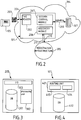
- an initial communication device 101 is represented in a communication session 103 with a remote communication device 102. Any one of the initial communication device 101 and the remote communication device 102 is initiator of the communication session.
- the initial communication device 101 and the remote communication device 102 are exchanging media streams, as represented by arrows 103.
- the initial communication device 101 is registered in a private network 104 and is handled by a home communication node 107.
- the home communication node 107 handles all communication sessions for the initial communication device 101 and will be described herein below in more details with reference to Figure 4 .
- the user of the initial communication device 101 moves to a place where a target communication device 105 is available.
- the target communication device 105 belongs to a private network 106.
- the user wants to shift the communication session, i.e. the media streams 103, from the initial communication device 101 to the target communication device 105, as represented by arrow 107.
- the initial communication device 101 comprises specific functional modules that has subscribed to a service, as it will be described below.
- the initial communication device 101 comprises a tag reader 202 for reading an identification tag signal 204 carrying a communication device identifier of the target communication device 105.
- the identification tag signal 204 carries the communication device identifier identifying uniquely the target communication device 105 in a registration service infrastructure 205.
- the user has to bring himself close to the target communication device 105 in order to be able to pick up the target communication device 105 when the target communication device 105 rings.
- Short distance refers to a distance lower than a short walk for the user to access a target communication device after the user scanned the identification signal thanks to the tag reader 202.
- the identification tag signal 204 could be either a radio or infrared digital signal broadcasted by the target communication device 105 itself or carrying picture or string of characters printed on a printable identification tag, e.g. a sticker, arranged on or near the target communication device 105.
- the tag reader 202 reads an identification tag 203, and the represented passive identification tag 203 carries the identifier coded as a Quick Response (QR) code.
- QR Quick Response
- any other coding format may be used instead of the QR code, for example barcode, for example a two dimensional barcode.
- the identification tag 203 may include a passive digital signal transmitter, such as a Near Field Communication (NFC) tag, or an Ultra High Frequency (UHF) tag.
- NFC Near Field Communication
- UHF Ultra High Frequency
- the tag reader 202 employs a reading technology which is adapted to each identification tag 203: radio technology, optical technology, passive technology or active technology, depending on which kind of identification tag is deployed.
- the initial communication device 101 further comprises a discovery module 206 for accessing the registration service infrastructure 205 and a session control module 207 for establishing and controlling communication sessions through the private network 104 by exchanging signaling messages 209.
- the functionality of the registration service infrastructure 205 will now be described in relation with the target communication device 105 and the initial communication device 101. Two different functions are set up in the registration service infrastructure 205.
- a first function is a subscription function that enables a registering communication device to subscribe to a service.
- the subscription function is illustrated in relation to the target communication device 105 in Figure 6 .
- a second function is a discovery function that enables a requesting communication device to get network location information for a registered communication device, and to check the integrity and validity of the network location information.
- the discovery function is illustrated in relation to the initial communication device 101 in Figure 6 .
- Figure 6 illustrates the subscription function by showing the target communication device 105 registering to the registration service in the registration service infrastructure 205, as shown by arrow 603.
- the registration service infrastructure 205 receives information, and generates and stores a communication device identifier.
- the registration service is a web service.
- a user of the target communication device 105 then makes the communication device identifier available by an identification tag previously described. Some of them are illustrated: QR identification tag 203, passive NFC tag 601 and active Bluetooth tag 602. In all cases, an identification signal 204 carrying the communication device identifier of the communication device can be read by an appropriate tag reader 202.
- the tag reader 202 embedded in the initial communication device 101 reads the identification signal 204.
- Figure 6 illustrates the discovery function by showing the registration service infrastructure 205 receiving the discovery request 210 from the initial communication device 101.
- the registration service infrastructure 205 sends back the discovery response 211 whose content will be later described.
- the discovery request 210 is an HTTP request.
- the structure of the registration service infrastructure 205 is represented in more details with reference to Figure 3 .
- the registration service infrastructure 205 comprises a registration data repository 301, a data processing unit 302 and a network interface 303.
- a registration request comprises network location information of a registering communication device.
- the data processing unit 302 is configured to generate a communication device identifier associated with the registering communication device.
- This identifier is the digest result of a one-way hash function, for instance the hash function SHA256 from the SHA2 hash family functions.
- the target communication device 105 sends a registering request to the registration service infrastructure 205 through the network interface 303.
- the registering request is an HTTP request using a secured protocol ensuring confidentiality and integrity of exchanged messages, and strong authentication of the registration service infrastructure.
- This protocol can be any application protocol over the transport layer protocol TLS (Transport Layer Security).
- TLS Transport Layer Security
- the data processing unit 302 therefore generates a communication device identifier for the target communication device 105.
- This identifier is generated using a one-way hash function taking as input the data contained in the registering request. For the sake of simplicity, let us say that the generated communication device identifier is the reference numeral "105".
- the data processing unit 302 is also configured to store into the registration data repository 301 the generated device identifier, in association with the received network location information.
- the data processing unit 302 stores into the registration data repository 301 the numeral "105" in association with the network location information of the target communication device 105.
- the associated network location information received from the target communication device 105 is an external phone number: +33390123456. Therefore, the data processing unit 302 stores into the registration data repository 301 the numeral "105" in association with the phone number "+33390123456".
- the data processing unit 302 is further configured to send to the registering communication device the generated device identifier through the network interface 303.
- the data processing unit 302 sends to the target communication device 105 the numeral "105".
- the subscription process which was just described in relation to the target communication device 105 may be performed from a different console than the communication device 105 itself.
- a network management console connected to the Internet is employed for populating the data repository 301.
- the subscription function is accessed through a web portal by any computer connected to the Internet.
- the registration data repository 301 stores a plurality of communication device identifiers. Each device identifier is stored in association with network location information of a registered communication device.
- the network location information comprises information for switching communication sessions to the registered communication device.
- the network location information consists of a public identifier of the communication device.
- the registration data repository 301 comprises a table in which communication device identifiers and associated network location information are stored as follows: Identifier of the communication device network location information Public identifier of the communication device 105 External phone number of the deskphone 105: +33390123456 Identifier of a digital tablet DT Session Initiation Protocol (SIP) Uniform Resource Identifier (URI) of the digital tablet DT: sip:myTablet@al-enterprise.com Identifier of a computer C SIP URI of the computer C: sip:myComputer@al-enterprise.com
- SIP Session Initiation Protocol
- URI Uniform Resource Identifier
- a registered communication device shares the following network location information related to its identity through the registration service infrastructure 205:
- All the shared network location information and supplementary information are stored in the registration data repository 301 in association with the generated communication device identifiers.
- the registration service infrastructure 205 comprises a network interface 303.
- the network interface 303 is further configured for receiving discovery requests 210 from the discovery module 206 of a requesting communication device and answering discovery responses 211 to the discovery module 206 of the requesting communication device, as shown by the arrows.
- the discovery request 210 is an HTTP request to the web service.
- the discovery requests 210 and discovery response 211 are transmitted over the network through a secured transport protocol (e.g. TLS) that ensures confidentiality and integrity of the transported information, and strong authentication of the registration service infrastructure by the requesting communication device thanks to its associated server certificate (e.g. using X.509v3 digital certificates).
- This protocol can be any application protocol over the transport layer protocol TLS (Transport Layer Security).
- the requesting communication device is the initial communication device 101 introduced in Figure 1 and the discovery request 210 comprises the communication device identifier of the target communication device 105, which is comprised in the identification signal 204 received by the tag reader 202.
- the data processing unit 302 of the registration service infrastructure 205 is configured to retrieve the network location information and optionally supplementary information associated with the communication device identifier of the target communication device 105 from the registration data repository 301.
- the network interface 303 is further configured to send the discovery response 211 to the requesting communication device, i.e. in the previous example the initial communication device 101.
- the discovery response 211 comprises the retrieved network location information and supplementary information as the case may be.
- the discovery response 211 further comprises the hashcode that is a digest value computed at the subscription step with a hash function.
- this hashcode is the result of the transformation of the network location information and supplementary information through a one-way hash function. Thanks to the properties of digest obtained from hash functions, this hashcode is unique to the communication device identifier and non reversibler. Such hashed identifier is precomputed during subscription step and stored in the database 301.
- the discovery module 206 of the initial communication device 101 is configured to apply the same hash function on the target communication device identifier received from the identification signal 204 in order to get a calculated encrypted communication device identifier.
- the discovery module 206 of the initial communication device 101 obtains the hashcode from the discovery response 211 and then compares it with the communication device identifier read in the tag in order to test equality between both.
- the integrity of the target communication device identifier is ensured and derived from the secured and authenticated initial request, in order to protect end users from illegitimate attempts of re-routing media of the communication session to an untrusted communication device.
- the QR identification tag 203 could be forged manually in an attempt to take control of the media for malicious purposes, for instance, for redirecting the media over a premium rate audio service without the consent of the user.
- the session control module 207 of the initial communication device 101 will be able to communicate to the private network 104 the necessary network location information for shifting a current communication session to the target communication device 105.
- a main actor of the shifting of the communication session to the target communication device 105 is the home communication node 107 of the initial communication device 101.
- the home communication node 107 comprises a routing unit 401 and a database 402 which contains registration information for all communication terminals belonging to private network 104.
- the routing unit 401 comprises a routing controller 403 for receiving signaling messages 209 from all communication devices belonging to private network 104 and establishing and handling communication sessions involving one of these communication devices.
- the routing unit 401 also comprises a media node 404 for transmitting media from a communication device of private network 104 to any communication device, belonging to the same private network 104 or not.
- the media node 404 is a media gateway which enables the transmission of media streams and transcoding operation on the media streams, i.e. for example transforming VoIP media streams into analogical media streams, or changing the format of the media streams incoming from an external network into a format adapted to the internal network.
- the media node 404 is a media gateway without any transcoding function. In such case, the media node 404 transmits media streams, for example Real Time Packet (RTP) fluxes, without any change.
- RTP Real Time Packet
- the home communication node 107 is a Private Branching Exchange (PBX) connected to the Internet or to the public switched telephonic network.
- PBX Private Branching Exchange
- a PBX is a server dedicated to the establishment of communication sessions between a plurality of communication devices belonging to a same private network, e.g. all communication devices of a company are connected to the PBX of the company, either by a wired connection or a wireless connection, thanks to a dedicated software application.
- the plurality of communication devices of a same private network are interconnected and registered in the PBX which routes the communication messages from and to them.
- the PBX also enables the establishment of communication sessions between a communication device of the private network 104 and other communication devices connected to the private network 104.
- the PBX also enables the establishment of communication sessions between a communication device of the private network 104 and communication devices connected to external networks.
- the initial communication device 101 belonging to the private network 104 can communicate with the remote communication device 102, regardless of whether the remote communication device 102 belongs to the private network 104 or not.
- the communication session is a call session between the user of the initial communication device 101 and the user of the remote communication device 102.
- the initial communication device 101 is a mobile phone and the remote communication device 102 is a deskphone.
- the deskphone calls the mobile phone.
- the call is routed by the telecom operator of the network infrastructure of the deskphone, for example the Internet Service Provider "Free", to the home communication node 107, in which the initial communication device 101 is registered, i.e. the PBX of the call destination.
- the routing controller 403 of the home communication node 107 routes the call in the private network 104 in order to reach the initial communication device 101.
- the initial communication device 101 rings and the user of the initial communication device 101 picks up the mobile phone to answer the call.
- the communication session involving the initial communication device 101 and the remote communication device 102 is established.
- the initial communication device 101 is any of the following: a deskphone, a mobile phone, a digital tablet, a computer with embedded communication application, e.g. Skype.
- the addresses of the communication devices which are belonging to the private network 104 are registered in the database 402 of the home communication node 107.
- the database of the home communication node 107 comprises a look-up table as follows: Identifier of the communication device Address of the communication device A Mobile phone number of the mobile phone A B IP address of the digital tablet B C IP address of the computer C D Phone number of the deskphone D E Phone number of the initial communication device 101 (Either the GSM number, or an internal number associated with the GSM number)
- Figure 1 shows a very simplified overview of the private network 104
- Figure 5 provides a more detailed implementation of the private communication network that can be employed in Figure 1 .
- the home communication node 107 is a PBX 504. Elements that are identical or similar to those of Figure 1 are designated by the same reference numeral as in Figure 1 .
- Figure 5 illustrates the private network 104 for the case of a two-site company. In a first site 515 of the company, a plurality of communication terminals 511, 512, 513 and 514 are connected through a Local Area Network (LAN) 505. In a second site 516 of the company, a plurality of communication terminals 510, 509 and 508 are connected through a Local Area Network (LAN) 507.
- LAN Local Area Network
- the two sites 515 and 516 are interconnected through a Wide Area Network (WAN) 506.
- WAN Wide Area Network
- An internal communication session between any two of the communication terminals of the private network 104 of the company is established through the PBX 504, which is a communication switch.
- the PBX 504 is also an endpoint of external networks, i.e. other networks than the private communication network.
- an external network 503 is represented.
- the external network 503 may be the Internet, or a carrier network. Therefore, the PBX 504 is configured as an interface between the private network 104 and external communication networks.
- the PBX 504 enables any communication device belonging to the private network 104 to call the target communication device 105, which is in this illustrative example connected to the external network 503 and not belonging to the private network 104.
- the private network 104 also comprises the initial communication device 101, which is in this illustrative example a mobile phone.
- the initial communication device 101 is connected to the PBX 504 through a cellular, e.g. Global System for Mobile Communications (GSM) or UMTS infrastructure.
- GSM Global System for Mobile Communications
- UMTS Universal Mobile Telecommunications
- the initial communication device 101 is located in a cell 501 comprising a base transceiver station 502 which is the antenna for emitting and receiving media to and from the initial communication device 101.
- the base transceiver station 502 is connected to a base station controller 517 for controlling one or more base transceiver stations 502, 524.
- the base station controller 517 is connected to a mobile switching center (MSC) 518 which routes the media to and from the initial communication device 101 to the PBX 504, as shown by dashed-line arrow 519.
- the GSM infrastructure also comprises Home Location Register (HLR) 520 for registering addresses of subscribing communication devices and Visiting Location Register (VLR) 521 which is the register of visiting communication devices.
- HLR Home Location Register
- VLR Visit Location Register
- the BSC 517 and the cell 501 are comprised in a Base Station Sub-System (BSS) 523, which also comprises another cell 522.
- BSS Base Station Sub-System
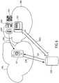
- Figures 7 and 8 correspond to two different cases.
- the initial communication device 101 and the target communication device 105 are belonging to the same private network 104.
- the home communication node 107 of the initial communication device 101 is therefore also the home communication node 107 of the target communication device 105.
- the initial communication device 101 sends a shift request 701 to the home communication node 107 for ordering the shifting of the communication session 103 to the target communication device 105.
- the shift request 701 comprises the network location information of the target communication device 105, e.g. the internal phone number of the target communication device 105.
- the home communication node 107 then shifts the communication session 103, i.e. re-route the media streams, to the target communication device 105.
- a new communication session 702 between the remote communication device 102 and the target communication device 105 is created, and the communication session 103 is over.
- the initial communication device 101 and the target communication device 105 are not belonging to the same private network 104.
- the initial communication device 101 belongs to the private network 104 whereas the target communication device 105 belongs to the network infrastructure 106.
- the initial communication device 101 sends the shift request 701 comprising network location information of the target communication device 105 to the home communication node 107.
- the home communication node 107 is the home communication node of the initial communication device 101.
- the home communication node 107 redirects the media by shifting the communication session 103 to the target communication device 105, as shown by the lines 702a and 702b, thanks to the network location information of the target communication device 105.
- the media should therefore be redirected through a carrier network 801 of the initial communication device 101.
- the initial communication device 101 must be close to the target communication device 105 to be able to read the identification indication broadcasted by this device, it is likely that the media streams emitted and received by the initial communication device 101 are attached to the home communication node through a mobile carrier network.
- the target communication device 105 is registered in the carrier network 801. This carrier network is interconnected with private network infrastructure 104 and 106 through SIP trunks or T2 trunks.
- the media are transmitted from the private network 104 to the carrier network 801 then to the network infrastructure 106 through Session Initiation Protocol (SIP) trunks represented by arrows 802 and 803.
- SIP Session Initiation Protocol
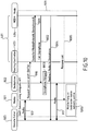
- the initial communication node 101 is a mobile phone 901
- the target communication node 105 is a deskphone 902
- the remote communication node 102 is referred to as a remote caller 903.
- a service subscription 904 of the deskphone 902 to the registration service infrastructure 205 is represented.
- the deskphone 902 sends a registering request 905 called SUBSCRIBE and comprising Data.
- the data comprises network location information as previously described with reference to Figure 3 .
- the registration service infrastructure 205 checks the data, signs the data, registers the data and generates the deskphone identifier (ID). Then, the registration service infrastructure 205 sends a registering response 906 comprising the ID and an integrity check value, i.e. encrypted ID, for example generated thanks to a hash function.
- the deskphone 902 displays the ID and the integrity check value, for example by means of a display screen.
- a user may print a passive tag, e.g. QR tag carrying the ID and the integrity check value and arranged the passive tag on the deskphone 902 or close to it.
- the mobile phone 901 scans the QR tag carrying the deskphone ID and integrity check value.
- the mobile phone 901 gets the deskphone ID and integrity check value in an identification signal 907, which consists of a digital image file in the present example.
- the mobile phone 901 sends a discovery request 210 comprising the ID and integrity check value to the registration service infrastructure 205.
- the registration service infrastructure 205 sends a discovery response 211 comprising data to the mobile phone 901.
- the data comprises the network location information of the deskphone 902.
- the mobile phone 901 then parses the received data.
- the session shifting stage 909 employs an adequate Application Programming Interface (API).
- API Application Programming Interface
- the mobile phone 901 sends a shift request 910 to the routing unit 401 of the home communication node of the mobile phone 901.
- the routing unit 401 triggers session shift on the three involved communication devices: the deskphone 902, the mobile phone 901 and the remote caller 903, such as to shift the communication session 103 from the mobile phone 901 to the deskphone 902.
- the communication session 103 is shifted and results in a communication session 911 between the remote caller 903 and the deskphone 902.
- the communication session 911 does not involve the mobile phone 901 anymore.
- Figure 10 and Figure 11 show two modified implementations of the session shifting stage 909 of Figure 9 .
- the remote caller 903 and the mobile phone 901 are in a communication session 103.
- the mobile phone 903 sends a shift request 910 to the routing unit 401 for shifting the communication session 103 to the deskphone 902 thanks to the data.
- the media streams are directly transferred in the new communication session 911.
- the shift request 910 arrives to the routing controller 403 of the routing unit 401.
- the routing controller 403 then sends a request 1001 to the media node 404 for transferring the media.
- the request 1001 comprises an identifier of the mobile phone 901 and an identifier of the deskphone 902 in order to allow the media node 404 to call the deskphone, as represented by the arrow 1002.
- the identifier of the deskphone 902 comes from the received data in the discovery response 211.
- the deskphone 902 is hung up by the user, as represented by the box 1003.
- the media node 404 therefore redirects the media to the deskphone, as shown by the arrow 1004, which results in the new communication session 911.
- the media node 404 orders the release of the call involving the mobile phone 901, as represented by the arrow 1005.
- the mobile phone 901 then hang on, as represented by the box 1006.
- Figure 11 illustrates a case in which the media streams are redirected from the communication session 103 to the new communication session 911 by way of a temporary conference bridge hosted in the home communication node 107.
- the shift request 910 arrives to the routing controller 403 of the routing unit 401.
- the routing controller 403 then sends a request 1001 to the media node 404 for switching the media streams.
- the request 1001 comprises an identifier of the mobile phone 901 and an identifier of the deskphone 902 in order to allow the media node 404 to call the deskphone, as represented by the arrow 1002.
- the identifier of the deskphone 902 comes from the data received in the discovery response 211.
- the media node Prior to calling the deskphone 902, the media node creates a temporary bridge and then redirects media streams to the temporary bridge, as shown by arrows 1011 and 1012.
- the temporary bridge allows mixing and redirecting media streams.
- Media streams are thus exchanged between the media node 404 and the mobile phone 901, and respectively between the media node 404 and the remote caller 903, as shown by arrows 1013 and 1014.
- the media node 404 temporarily exchanges media streams with the deskphone 902, as represented by arrow 1015.
- the mobile phone 901, the remote caller 903 and the deskphone 902 are therefore connected through a temporary bridge, as shown by the box 1016.
- the media node 404 orders the release of the call involving the mobile phone 901, as represented by the arrow 1005. Then, the media node 404 reconnects media leg to temporary media leg, as shown by arrow 1017, resulting in the communication session 911 between the remote caller 903 and the deskphone 902.
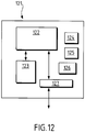
- FIG. 12 illustrates a computing device 121 which can be used for implementing any of the following: registration service infrastructure, communication devices, home communication node and PBX.
- the computing device 121 comprises a data repository 122 connected to a processing unit 123 and to a communication interface 127.
- the data repository is a hard drive, a ROM, a RAM or other.
- the computing device 121 also comprises an input device 124, an output device 125 and an analog-to-digital and/or digital-to-analog converter 126.
- the input device 124 is a mouse, a joystick, a touch screen, a voice recorder etc.
- the output device 125 is a display device such as a two-dimensional screen or a three-dimensional screen.
- the communication interface 127 is connected to other devices and/or to the Internet in various manners, e.g. through a wired and/or a wireless connection, e.g. Wi-Fi, Bluetooth, etc.
- the invention is not limited to the above description but to the scope as defined by the appended claims.
- the use of the verb "to comprise” or “to include” and its conjugations does not exclude the presence of elements or steps other than those stated in a claim.
- the use of the article “a” or “an” preceding an element or step does not exclude the presence of a plurality of such elements or steps.
- the invention may be implemented by means of hardware as well as software.
- the registration service infrastructure, communication devices, home communication node and PBX, described hereinabove may be implemented through the use of dedicated hardware as well as hardware capable of executing software in association with appropriate software.
- the corresponding functions may be provided by a single dedicated processor, by a single shared processor, or by a plurality of individual processors, some of which may be shared.
- the term "hardware” should not be construed to refer exclusively to hardware capable of executing software, and may include, without limitation, central processing unit (CPU), digital signal processor (DSP) hardware, network processor, application specific integrated circuit (ASIC), field programmable gate array (FPGA), read-only memory (ROM) for storing software, random access memory (RAM), and non-volatile storage. Other hardware, conventional and/or custom, may also be included.
- the registration service infrastructure described hereinabove may be implemented in a unitary manner or in a distributed manner. In the claims, any reference signs placed between parentheses shall not be construed as limiting the scope of the claims.
Landscapes
- Engineering & Computer Science (AREA)
- Computer Networks & Wireless Communication (AREA)
- Signal Processing (AREA)
- Computer Security & Cryptography (AREA)
- Business, Economics & Management (AREA)
- General Business, Economics & Management (AREA)
- Multimedia (AREA)
- Computer Hardware Design (AREA)
- Computing Systems (AREA)
- General Engineering & Computer Science (AREA)
- Mobile Radio Communication Systems (AREA)
Description
- The invention relates generally to a system and a method for shifting a communication session from an initial communication device to a target communication device, especially when the initial communication device and the target communication device do not belong to the same private network.
- Communication systems are known wherein a communication session is firstly launched between a first phone and a second phone, wherein the first phone belongs to a private network, and the communication session is secondly shifted from the first phone to a third phone belonging to the same private network. As employed herein, a communication device belongs to a private network means that the communication device is connected to a private communication network of an organization by the Private Branching Exchange (PBX) of the organization.
- Prior art
US 2007/032225 A1 shows how to automatically and seamlessly transfer an existing call from a user's cell phone to a VoIP capable computer operating on a wireless network without terminating the existing call. A user's mobile communication device is configured with user-defined preferences that include an identifier of user's alternative communication device and that define a specified location for initiating call forwarding operation when the user approaches this location. The incoming calls intended for user's mobile communication device are automatically forwarded to alternative communication device identified using user-defined preferences, upon determining that the user's mobile communication device is within range of the said user-defined location. - An idea at the basis of the invention is to provide secured identification of communication devices homogeneously in a complex heterogeneous communication system, for example a communication system comprising communication devices belonging to different private networks. An idea at the basis of the invention is to provide communication session shifting functions between communication devices belonging to different private networks.
- In an embodiment, a method for shifting from a first to a second communication is provided as in
claim 1. In another embodiment, a communication device with communication shifting capabilities is provided as in claim 2. In yet another embodiment, a communication system comprising a communication device with communication shifting capabilities and a registration service infrastructure is provided as in claim 3. Other embodiments are provided in dependent claims. - The aspects of the invention will be apparent from and elucidated with reference to the embodiments described hereinafter, by way of example, with reference to the drawings.
-
Figure 1 schematically illustrates an initial communication device in a communication session with a remote communication device, shifting the communication session to a target communication device, according to an embodiment of the invention; -
Figure 2 schematically illustrates the initial communication device ofFigure 1 , according to an embodiment; -
Figure 3 schematically illustrates a registration service infrastructure; -
Figure 4 schematically illustrates a home communication node which handles all communication sessions with the initial communication device of theFigure 1 ; -
Figure 5 schematically illustrates the network infrastructure of the initial communication device ofFigure 2 ; -
Figure 6 schematically illustrates the target communication device ofFigure 1 registering to the registration service in the registration service infrastructure ofFigure 3 , and the initial communication device receiving a communication device identifier of the target communication device from an identification tag, and checking the validity of the communication device identifier with the registration service; -
Figure 7 schematically illustrates the home communication node ofFigure 4 re-routing media from the initial communication device ofFigure 1 to the target communication device ofFigure 3 when the initial communication device and the target communication device are in the same private network, in order to shift the communication session from the initial communication device to the target communication device; -
Figure 8 schematically illustrates the home communication node ofFigure 4 re-routing media from the initial communication device ofFigure 1 to the target communication device ofFigure 3 through a carrier network when the initial communication device and the target communication device are in different private networks, in order to shift the communication session from the initial communication device to the target communication device; -
Figure 9 is a call flow of messages represented onFigure 5 andFigure 7 ; -
Figure 10 andFigure 11 are call flows representing two different embodiments for shifting the communication session from the initial communication device to the target communication device; -
Figure 12 schematically illustrates a computing device according to an embodiment. - With reference to
Figure 1 , aninitial communication device 101 is represented in acommunication session 103 with aremote communication device 102. Any one of theinitial communication device 101 and theremote communication device 102 is initiator of the communication session. Theinitial communication device 101 and theremote communication device 102 are exchanging media streams, as represented byarrows 103. Theinitial communication device 101 is registered in aprivate network 104 and is handled by ahome communication node 107. Thehome communication node 107 handles all communication sessions for theinitial communication device 101 and will be described herein below in more details with reference toFigure 4 . - The user of the
initial communication device 101 moves to a place where atarget communication device 105 is available. Thetarget communication device 105 belongs to aprivate network 106. For any reason, the user wants to shift the communication session, i.e. themedia streams 103, from theinitial communication device 101 to thetarget communication device 105, as represented byarrow 107. - Some possible reasons or purposes for which a user may want to shift the communication session from the
initial communication device 101 to thetarget communication device 105 are stated below: - to move an ongoing multi-media communication toward a
target communication device 105 having better audio and/or video quality rendering than theinitial communication device 101. - to experience multi-media communications on a
target communication device 105 with better media quality than on theinitial communication device 101. For example, thetarget communication device 105 may be a desk computer, whereas theinitial communication device 101 may be a mobile data tablet; - to lower the communication costs by using device having local communication links (mobile or fixe, foreign mobile carrier...). For example, the
initial communication device 101 is a smartphone and thetarget communication device 105 is a deskphone. - to leverage added services on a local device (local contact directory, collaboration tools such as conferencing). For example, the
target communication device 105 may be a conference device in a conference room, whereas theinitial communication device 101 may be a mobile phone; - to benefit from newest design or form factor. For example, the
target communication device 105 has a larger display than theinitial communication device 101, or theinitial communication device 101 does not have a keyboard whereas thetarget communication device 105 is equipped with a keyboard; - to avoid or remedy battery shortage. For example the battery of the
initial communication device 101 is very low and the use of theinitial communication device 101 wants to keep on being in communication; - to adapt a specific working environment, e.g. flex office or traveling workers
- In order to shift the communication session from the
initial communication device 101 to thetarget communication device 105, theinitial communication device 101 comprises specific functional modules that has subscribed to a service, as it will be described below. - With reference to
Figure 2 , some specific functional modules embedded in theinitial communication device 101 represented onFigure 1 will now be described. While this description focuses on aspects of theinitial communication device 101 that serve to implement a session shifting function, it does not preclude the presence of further conventional components in theinitial communication device 101, e.g. data processing means, voice communication means, and human-machine interfaces. - The
initial communication device 101 comprises atag reader 202 for reading anidentification tag signal 204 carrying a communication device identifier of thetarget communication device 105. Theidentification tag signal 204 carries the communication device identifier identifying uniquely thetarget communication device 105 in aregistration service infrastructure 205. - The user has to bring himself close to the
target communication device 105 in order to be able to pick up thetarget communication device 105 when thetarget communication device 105 rings. - Therefore, the
identification tag signal 204 should be accessed from a very short distance from thetarget communication device 105. Short distance refers to a distance lower than a short walk for the user to access a target communication device after the user scanned the identification signal thanks to thetag reader 202. - The
identification tag signal 204 could be either a radio or infrared digital signal broadcasted by thetarget communication device 105 itself or carrying picture or string of characters printed on a printable identification tag, e.g. a sticker, arranged on or near thetarget communication device 105. - For the sake of illustration, the
tag reader 202 reads anidentification tag 203, and the representedpassive identification tag 203 carries the identifier coded as a Quick Response (QR) code. Generally, any other coding format may be used instead of the QR code, for example barcode, for example a two dimensional barcode. - Alternatively, the
identification tag 203 may include a passive digital signal transmitter, such as a Near Field Communication (NFC) tag, or an Ultra High Frequency (UHF) tag. - The
tag reader 202 employs a reading technology which is adapted to each identification tag 203: radio technology, optical technology, passive technology or active technology, depending on which kind of identification tag is deployed. - The
initial communication device 101 further comprises adiscovery module 206 for accessing theregistration service infrastructure 205 and asession control module 207 for establishing and controlling communication sessions through theprivate network 104 by exchangingsignaling messages 209. - With reference to
Figure 6 , the functionality of theregistration service infrastructure 205 will now be described in relation with thetarget communication device 105 and theinitial communication device 101. Two different functions are set up in theregistration service infrastructure 205. - A first function is a subscription function that enables a registering communication device to subscribe to a service. The subscription function is illustrated in relation to the
target communication device 105 inFigure 6 . A second function is a discovery function that enables a requesting communication device to get network location information for a registered communication device, and to check the integrity and validity of the network location information. The discovery function is illustrated in relation to theinitial communication device 101 inFigure 6 . -
Figure 6 illustrates the subscription function by showing thetarget communication device 105 registering to the registration service in theregistration service infrastructure 205, as shown byarrow 603. Theregistration service infrastructure 205 receives information, and generates and stores a communication device identifier. The registration service is a web service. - A user of the
target communication device 105 then makes the communication device identifier available by an identification tag previously described. Some of them are illustrated:QR identification tag 203,passive NFC tag 601 andactive Bluetooth tag 602. In all cases, anidentification signal 204 carrying the communication device identifier of the communication device can be read by anappropriate tag reader 202. - The
tag reader 202 embedded in theinitial communication device 101 reads theidentification signal 204. -
Figure 6 illustrates the discovery function by showing theregistration service infrastructure 205 receiving thediscovery request 210 from theinitial communication device 101. Theregistration service infrastructure 205 sends back thediscovery response 211 whose content will be later described. Thediscovery request 210 is an HTTP request. - The structure of the
registration service infrastructure 205 is represented in more details with reference toFigure 3 . Theregistration service infrastructure 205 comprises aregistration data repository 301, adata processing unit 302 and anetwork interface 303. - To perform the subscription function, the
network interface 303 is configured to receive registering requests from registering communication devices. This will be explained in more details with reference toFigure 8 . A registration request comprises network location information of a registering communication device. - The
data processing unit 302 is configured to generate a communication device identifier associated with the registering communication device. This identifier is the digest result of a one-way hash function, for instance the hash function SHA256 from the SHA2 hash family functions. - For example, the
target communication device 105 sends a registering request to theregistration service infrastructure 205 through thenetwork interface 303. The registering request is an HTTP request using a secured protocol ensuring confidentiality and integrity of exchanged messages, and strong authentication of the registration service infrastructure. This protocol can be any application protocol over the transport layer protocol TLS (Transport Layer Security). Thedata processing unit 302 therefore generates a communication device identifier for thetarget communication device 105. This identifier is generated using a one-way hash function taking as input the data contained in the registering request. For the sake of simplicity, let us say that the generated communication device identifier is the reference numeral "105". - The
data processing unit 302 is also configured to store into theregistration data repository 301 the generated device identifier, in association with the received network location information. - For example, the
data processing unit 302 stores into theregistration data repository 301 the numeral "105" in association with the network location information of thetarget communication device 105. For example, the associated network location information received from thetarget communication device 105 is an external phone number: +33390123456. Therefore, thedata processing unit 302 stores into theregistration data repository 301 the numeral "105" in association with the phone number "+33390123456". - The
data processing unit 302 is further configured to send to the registering communication device the generated device identifier through thenetwork interface 303. - For example, the
data processing unit 302 sends to thetarget communication device 105 the numeral "105". - The subscription process which was just described in relation to the
target communication device 105 may be performed from a different console than thecommunication device 105 itself. In an embodiment, a network management console connected to the Internet is employed for populating thedata repository 301. In an embodiment, the subscription function is accessed through a web portal by any computer connected to the Internet. - Therefore, the
registration data repository 301 stores a plurality of communication device identifiers. Each device identifier is stored in association with network location information of a registered communication device. The network location information comprises information for switching communication sessions to the registered communication device. - In a very simple embodiment, the network location information consists of a public identifier of the communication device. For example, the
registration data repository 301 comprises a table in which communication device identifiers and associated network location information are stored as follows:Identifier of the communication device network location information Public identifier of the communication device 105 External phone number of the deskphone 105: +33390123456 Identifier of a digital tablet DT Session Initiation Protocol (SIP) Uniform Resource Identifier (URI) of the digital tablet DT: sip:myTablet@al-enterprise.com Identifier of a computer C SIP URI of the computer C: sip:myComputer@al-enterprise.com - In a more complete embodiment, a registered communication device shares the following network location information related to its identity through the registration service infrastructure 205:
- 1. An identifier of the registered communication device infrastructure, e.g. the communication server FQDN;
- 2. One or several local private identifiers of the registered communication device in its infrastructure;
- 3. One or several public identifiers of the registered communication device. These identifiers depend on the public communication infrastructures the registered communication device system is connected with.
- The kind of media supported or allowed by the registered communication device, e.g. video media
- Some restrictions depending on the session shift context, e.g. hourly access restriction or call destination limitations.
         <Devicelnfos>
           <InfrastructureId>https://www.mycompany.com</InfrastructureId>
           <Services>
                   <Media>
                             <Medium>audio</Medium>
                             <Medium>video</Medium>
                             <Medium>chat</Medium>
                   </Media>
          </Services>
           <Deviceld>
                   <Internal>20012345</Internal>
                   <External>+33390612345</External>
          </DeviceId>
         </DeviceInfos>
For example, the network location information and supplementary information are json formatted and looks like the following:
         {"DeviceInfos": {
           "InfrastructureId": "https://www.mycompany.com",
           "Services":{
                    "Media": [
                             "Medium":"audio",
                             "Medium":"video",
                             "Medium":"chat"
                             ]
                    },
          "Deviceld":{
                    "Internal":"20012345 ",
                    "External":"+ 33390612345"
                    },
          "TimeOut":"3600"
          }
         }
| Identifier of the communication device | Address of the communication device |
| A | Mobile phone number of the mobile phone A |
| B | IP address of the digital tablet B |
| C | IP address of the computer C |
| D | Phone number of the deskphone D |
| E | Phone number of the initial communication device 101 (Either the GSM number, or an internal number associated with the GSM number) |
The registration service infrastructure, communication devices, home communication node and PBX, described hereinabove may be implemented through the use of dedicated hardware as well as hardware capable of executing software in association with appropriate software. When provided by a processor, the corresponding functions may be provided by a single dedicated processor, by a single shared processor, or by a plurality of individual processors, some of which may be shared. Moreover, the term "hardware" should not be construed to refer exclusively to hardware capable of executing software, and may include, without limitation, central processing unit (CPU), digital signal processor (DSP) hardware, network processor, application specific integrated circuit (ASIC), field programmable gate array (FPGA), read-only memory (ROM) for storing software, random access memory (RAM), and non-volatile storage. Other hardware, conventional and/or custom, may also be included. The registration service infrastructure described hereinabove may be implemented in a unitary manner or in a distributed manner.
In the claims, any reference signs placed between parentheses shall not be construed as limiting the scope of the claims.
Claims (5)
- A method for shifting from a first communication session (103) through a home communication node (107), between an initial communication device (101) registered with the home communication node (107), and a remote communication device (102), to a second communication session (702) through the home communication node (107), between a target communication device (105) and the remote communication device (102), comprising:- registering by the target communication device (105) with a registration service infrastructure (205), comprising:- receiving (905) by the registration service infrastructure (205) a registration request (603) from the target communication device (105), the registration request (603) comprising a network location information of the target communication device (105);- generating by the registration service infrastructure (205) a communication device identifier, wherein the communication device identifier is generated using a cryptographic function applied to the network location information;- storing at the registration service infrastructure (205) the generated communication device identifier in association with the received network location information;- sending (906) by the registration service infrastructure (205) to the target communication device (105) the generated communication device identifier; and- generating at the target communication device (105) an identification tag signal (204) comprising the generated communication device identifier, located in, on or at a short distance from the target communication device (105);- reading by the initial communication device (101) the identification tag signal (204);- sending by the initial communication device (101) a discovery request (210) to the registration service infrastructure (205), wherein the discovery request (210) comprises the generated communication device identifier;- receiving by the initial communication device (101) a discovery response (211) from the registration service infrastructure (205), the discovery response comprising the network location information of the target communication device (105);- generating by the initial communication device (101) a calculated communication device identifier, by applying the cryptographic function to the network location information;- comparing by the initial communication device (101) the calculated communication device identifier with the generated communication device identifier read from the identification tag signal (204), and if there is equality between the two:- sending by the initial communication device (101) a shift request (910) to the home communication node (107) for shifting the first communication session (103) to the second communication session (702), the shift request comprising the network location information of the target communication device (105), and- terminating by the initial communication device (101) the first communication session (103).
- A communication device (101) comprising:- a tag reader (202) configured to receive an identification tag signal (204) comprising a communication device identifier of a target communication device (105), the tag signal having been generated by the target communication device (105), the communication device identifier having been generated by a registration service infrastructure (205) upon registration of the target communication device (105), using a cryptographic function applied to a network location information of the target communication device (105), wherein the identification tag signal is received from an identification tag located in, on or at a short distance from the target communication device;- a discovery module (206) configured to:- send a discovery request (210) to the registration service infrastructure (205), wherein the registration service infrastructure comprises a registration data repository in which the network location information of the target communication device (105) is stored in association with the communication device identifier of the target communication device (105), wherein the discovery request (210) comprises the communication device identifier comprised in the received identification tag signal (204);- receive a discovery response (211) from the registration service infrastructure (205), the discovery response (211) comprising the network location information of the target communication device (105);- generate a calculated communication device identifier, by applying the cryptographic function to the received network location information; and- compare the calculated communication device identifier with the communication device identifier read from the identification tag signal (204); and- a session control module (207) configured to, if there is equality between the calculated communication device identifier and the communication device identifier read from the identification tag signal (204):- send a shift request (910) to a home communication node (107) with which the communication device (101) is registered, for shifting from a first communication session (103) established through the home communication node (107) between the communication device (101) and a remote communication device (102), to a second communication session (702) established through the home communication node (107) between the target communication device (105) and the remote communication device (102), wherein the home communication node (107) handles all communication sessions for the communication device (101), the shift request (910) comprising the network location information of the target communication device (105); and- terminate the first communication session (103).
- A communication system comprising a communication device (101) and a registration service infrastructure (205),
wherein the registration service infrastructure (205) comprises a registration data repository (301), a data processing unit (302) and a network interface (303), wherein:- the network interface (303) is configured to receive a registration request (603) from a target communication device (105), the registration request (603) comprising network location information of the target communication device (105);- the data processing unit (302) is configured to generate a communication device identifier using a cryptographic function applied to the network location information;- the registration data repository (301) is configured to store the generated communication device identifier in association with the received network location information;- the network interface (303) is further configured to send to the target communication device (105) the generated communication device identifier;- the network interface (303) is further configured to receive a discovery request (210) from the communication device (101), wherein the discovery request (210) comprises the generated communication device identifier;- the data processing unit (302) is further configured to retrieve the network location information associated with the generated communication device identifier; and- the network interface (303) is further configured to send a discovery response (211) to the communication device (101), wherein the discovery response (211) comprises the retrieved network location information;wherein the communication device (101) comprises a tag reader (202), a discovery module (206), and a session control module (207), wherein:- the tag reader (202) is configured to receive an identification tag signal (204) comprising the communication device identifier of the target communication device (105), the tag signal having been generated by the target communication device (105), wherein the identification tag signal is received from an identification tag located in, on or at a short distance from the target communication device;- the discovery module (206) is configured to:- send the discovery request (210) to the registration service infrastructure (205);- receive the discovery response (211) from the registration service infrastructure (205);- generate a calculated communication device identifier, by applying the cryptographic function to the retrieved network location information; and- compare the calculated communication device identifier with the communication device identifier read from the identification tag signal (204); and- a session control module (207) configured to, if there is equality between the calculated communication device identifier and the communication device identifier read from the identification tag signal (204):- send a shift request (910) to a home communication node (107) with which the communication device (101) is registered, for shifting from a first communication session (103) established through the home communication node (107) between the communication device (101) and a remote communication device (102), to a second communication session (702) established through the home communication node (107) between the target communication device (105) and the remote communication device (102), wherein the home communication node (107) handles all communication sessions for the communication device (101), the shift request (910) comprising the network location information of the target communication device (105); and- terminate the first communication session (103). - The communication system of claim 3, wherein the network location information further comprises a public identifier of the target communication device (105), wherein the public identifier of the target communication device (105) is an address of the target communication device in a public network to which the target communication device (105) is connected.
- The communication system of claim 3 or 4, wherein the network location information of the target communication device (105) comprises:- a local identifier of the target communication device (105), wherein the local identifier of the target communication device (105) is an address of the target communication device in a local network to which the target communication device is connected; and- an identifier of the home communication node (107) handling all communication sessions for the target communication device (105).
Applications Claiming Priority (2)
| Application Number | Priority Date | Filing Date | Title |
|---|---|---|---|
| EP15306846 | 2015-11-20 | ||
| PCT/IB2015/059775 WO2017085536A1 (en) | 2015-11-20 | 2015-12-18 | Method and system for shifting a communication session |
Publications (3)
| Publication Number | Publication Date |
|---|---|
| EP3378277A1 EP3378277A1 (en) | 2018-09-26 |
| EP3378277A4 EP3378277A4 (en) | 2019-04-24 |
| EP3378277B1 true EP3378277B1 (en) | 2020-08-19 |
Family
ID=54707721
Family Applications (1)
| Application Number | Title | Priority Date | Filing Date |
|---|---|---|---|
| EP15908690.9A Active EP3378277B1 (en) | 2015-11-20 | 2015-12-18 | Method and system for shifting a communication session |
Country Status (3)
| Country | Link |
|---|---|
| US (1) | US10484482B2 (en) |
| EP (1) | EP3378277B1 (en) |
| WO (1) | WO2017085536A1 (en) |
Families Citing this family (5)
| Publication number | Priority date | Publication date | Assignee | Title |
|---|---|---|---|---|
| DE102016000871A1 (en) * | 2016-01-27 | 2017-07-27 | Unify Gmbh & Co. Kg | Method for automatically transmitting an upcoming event via an interface to an end point assigned to a user, and a conversion device designed for this purpose |
| GB201703218D0 (en) * | 2017-02-28 | 2017-04-12 | Univ Surrey | Methods and apparatus for adaptive interaction with remote devices |
| CN109525571A (en) * | 2018-11-07 | 2019-03-26 | 紫光测控有限公司 | A kind of registration activation method and system of intelligent electronic device |
| JP2022549671A (en) * | 2019-09-25 | 2022-11-28 | コモンウェルス サイエンティフィック アンド インダストリアル リサーチ オーガナイゼーション | Cryptographic services for browser applications |
| CN116056028A (en) * | 2021-10-28 | 2023-05-02 | 华为技术有限公司 | Communication method and device |
Family Cites Families (16)
| Publication number | Priority date | Publication date | Assignee | Title |
|---|---|---|---|---|
| US7042879B2 (en) * | 2001-11-02 | 2006-05-09 | General Instrument Corporation | Method and apparatus for transferring a communication session |
| EP1330098A1 (en) * | 2002-01-21 | 2003-07-23 | BRITISH TELECOMMUNICATIONS public limited company | Method and communication system for data web session transfer |
| US20060036447A1 (en) * | 2002-05-15 | 2006-02-16 | Stefan Roever | Methods of facilitating contact management using a computerized system including a set of titles |
| US8880047B2 (en) | 2005-08-03 | 2014-11-04 | Jeffrey C. Konicek | Realtime, location-based cell phone enhancements, uses, and applications |
| US8078688B2 (en) * | 2006-12-29 | 2011-12-13 | Prodea Systems, Inc. | File sharing through multi-services gateway device at user premises |
| US8705720B2 (en) * | 2007-02-08 | 2014-04-22 | Avaya Inc. | System, method and apparatus for clientless two factor authentication in VoIP networks |
| US8230075B1 (en) * | 2008-11-15 | 2012-07-24 | Adobe Systems Incorporated | Method and device for identifying devices which can be targeted for the purpose of establishing a communication session |
| US8391224B2 (en) * | 2009-03-03 | 2013-03-05 | Avaya Inc. | Proactive load distribution for 802.111-based wireless LANs |
| US20150058409A1 (en) * | 2013-03-22 | 2015-02-26 | Frank C. Wang | Enhanced content delivery system and method spanning multiple data processing systems |
| US8856349B2 (en) | 2010-02-05 | 2014-10-07 | Sling Media Inc. | Connection priority services for data communication between two devices |
| MY171032A (en) * | 2010-10-22 | 2019-09-23 | Mimos Berhad | Location independent approach to session transfer for real-time voip session |
| EP2647190B1 (en) * | 2010-12-03 | 2019-10-16 | Unify Inc. | Method and apparatus for controlling sessions from one or more devices |
| US9363653B2 (en) | 2012-03-08 | 2016-06-07 | Intel Corporation | Transfer of communication from one device to another |
| US9131266B2 (en) * | 2012-08-10 | 2015-09-08 | Qualcomm Incorporated | Ad-hoc media presentation based upon dynamic discovery of media output devices that are proximate to one or more users |
| US9210198B2 (en) * | 2013-05-31 | 2015-12-08 | Vonage Networks Llc | Method and apparatus for transferring active communication session streams between devices |
| US10097984B2 (en) * | 2014-04-01 | 2018-10-09 | Belkin International, Inc. | IoT device environment detection, identification and caching |
-
2015
- 2015-12-18 WO PCT/IB2015/059775 patent/WO2017085536A1/en active Application Filing
- 2015-12-18 EP EP15908690.9A patent/EP3378277B1/en active Active
- 2015-12-18 US US15/777,569 patent/US10484482B2/en active Active
Non-Patent Citations (1)
| Title |
|---|
| None * |
Also Published As
| Publication number | Publication date |
|---|---|
| US20180338008A1 (en) | 2018-11-22 |
| EP3378277A4 (en) | 2019-04-24 |
| WO2017085536A1 (en) | 2017-05-26 |
| EP3378277A1 (en) | 2018-09-26 |
| US10484482B2 (en) | 2019-11-19 |
Similar Documents
| Publication | Publication Date | Title |
|---|---|---|
| US10419895B2 (en) | Method and system for identity management across multiple planes | |
| EP3378277B1 (en) | Method and system for shifting a communication session | |
| KR101260111B1 (en) | Personal network access control system and method | |
| US20060153172A1 (en) | Emergency call system and emergency call method | |
| US10291775B2 (en) | Communication termination using hunt groups and implicit registration | |
| JP2008245292A (en) | Providing routing information in communication system | |
| US20160113042A1 (en) | Method and apparatus for processing a communication request from a roaming voice over ip terminal | |
| US20210120416A1 (en) | Secure inter-mobile network communication | |
| CA2650262A1 (en) | Method and apparatus for processing session initiation protocol messages associated with a voice over ip terminal | |
| US8085759B2 (en) | Method for establishing a VoIP communication using a peer-to-peer databank | |
| US20130219070A1 (en) | Resolving device specific identifiers to a user identifier to initiate a dialog establishment with devices of a user | |
| WO2014173086A1 (en) | Information transmission and forwarding method and apparatus | |
| CN105471820A (en) | Processing method and processing device for converged communication terminal discovery and ability detection | |
| US9585018B2 (en) | Transit network communication routing | |
| CN101904148A (en) | Method and arrangement for network roaming of corporate extension identities | |
| CN100592747C (en) | Method for managing a communication with multi-server service providing means | |
| US8892139B2 (en) | Systems and methods enabling a short message service gateway via cloud computing services | |
| KR101978972B1 (en) | Improved automatic caller identification translation | |
| CN108140229A (en) | Send facility information application server of the service with the associated computing device of communication to | |
| JP4819716B2 (en) | Call control server and call control method | |
| JP6598629B2 (en) | Message transmission system | |
| US11653334B2 (en) | Systems and methods for reducing transcoding resource allocation during call setup to multiple terminations | |
| US20230156447A1 (en) | Roaming device location determination for emergency communications | |
| US8254876B1 (en) | Systems and methods for supporting dispatch communications | |
| CN107113303A (en) | The telephone number of multiple equipment association table one |
Legal Events
| Date | Code | Title | Description |
|---|---|---|---|
| STAA | Information on the status of an ep patent application or granted ep patent |
Free format text: STATUS: THE INTERNATIONAL PUBLICATION HAS BEEN MADE |
|
| PUAI | Public reference made under article 153(3) epc to a published international application that has entered the european phase |
Free format text: ORIGINAL CODE: 0009012 |
|
| STAA | Information on the status of an ep patent application or granted ep patent |
Free format text: STATUS: REQUEST FOR EXAMINATION WAS MADE |
|
| 17P | Request for examination filed |
Effective date: 20180615 |
|
| AK | Designated contracting states |
Kind code of ref document: A1 Designated state(s): AL AT BE BG CH CY CZ DE DK EE ES FI FR GB GR HR HU IE IS IT LI LT LU LV MC MK MT NL NO PL PT RO RS SE SI SK SM TR |
|
| AX | Request for extension of the european patent |
Extension state: BA ME |
|
| DAV | Request for validation of the european patent (deleted) | ||
| DAX | Request for extension of the european patent (deleted) | ||
| A4 | Supplementary search report drawn up and despatched |
Effective date: 20190322 |
|
| RIC1 | Information provided on ipc code assigned before grant |
Ipc: H04W 80/10 20090101AFI20190318BHEP Ipc: H04L 29/06 20060101ALI20190318BHEP |
|
| STAA | Information on the status of an ep patent application or granted ep patent |
Free format text: STATUS: EXAMINATION IS IN PROGRESS |
|
| 17Q | First examination report despatched |
Effective date: 20200122 |
|
| GRAP | Despatch of communication of intention to grant a patent |
Free format text: ORIGINAL CODE: EPIDOSNIGR1 |
|
| STAA | Information on the status of an ep patent application or granted ep patent |
Free format text: STATUS: GRANT OF PATENT IS INTENDED |
|
| GRAS | Grant fee paid |
Free format text: ORIGINAL CODE: EPIDOSNIGR3 |
|
| GRAA | (expected) grant |
Free format text: ORIGINAL CODE: 0009210 |
|
| STAA | Information on the status of an ep patent application or granted ep patent |
Free format text: STATUS: THE PATENT HAS BEEN GRANTED |
|
| INTG | Intention to grant announced |
Effective date: 20200623 |
|
| AK | Designated contracting states |
Kind code of ref document: B1 Designated state(s): AL AT BE BG CH CY CZ DE DK EE ES FI FR GB GR HR HU IE IS IT LI LT LU LV MC MK MT NL NO PL PT RO RS SE SI SK SM TR |
|
| REG | Reference to a national code |
Ref country code: CH Ref legal event code: EP |
|
| REG | Reference to a national code |
Ref country code: DE Ref legal event code: R096 Ref document number: 602015057910 Country of ref document: DE |
|
| REG | Reference to a national code |
Ref country code: AT Ref legal event code: REF Ref document number: 1305401 Country of ref document: AT Kind code of ref document: T Effective date: 20200915 |
|
| REG | Reference to a national code |
Ref country code: IE Ref legal event code: FG4D |
|
| REG | Reference to a national code |
Ref country code: LT Ref legal event code: MG4D |
|
| REG | Reference to a national code |
Ref country code: NL Ref legal event code: MP Effective date: 20200819 |
|
| PG25 | Lapsed in a contracting state [announced via postgrant information from national office to epo] |
Ref country code: GR Free format text: LAPSE BECAUSE OF FAILURE TO SUBMIT A TRANSLATION OF THE DESCRIPTION OR TO PAY THE FEE WITHIN THE PRESCRIBED TIME-LIMIT Effective date: 20201120 Ref country code: BG Free format text: LAPSE BECAUSE OF FAILURE TO SUBMIT A TRANSLATION OF THE DESCRIPTION OR TO PAY THE FEE WITHIN THE PRESCRIBED TIME-LIMIT Effective date: 20201119 Ref country code: FI Free format text: LAPSE BECAUSE OF FAILURE TO SUBMIT A TRANSLATION OF THE DESCRIPTION OR TO PAY THE FEE WITHIN THE PRESCRIBED TIME-LIMIT Effective date: 20200819 Ref country code: NO Free format text: LAPSE BECAUSE OF FAILURE TO SUBMIT A TRANSLATION OF THE DESCRIPTION OR TO PAY THE FEE WITHIN THE PRESCRIBED TIME-LIMIT Effective date: 20201119 Ref country code: SE Free format text: LAPSE BECAUSE OF FAILURE TO SUBMIT A TRANSLATION OF THE DESCRIPTION OR TO PAY THE FEE WITHIN THE PRESCRIBED TIME-LIMIT Effective date: 20200819 Ref country code: HR Free format text: LAPSE BECAUSE OF FAILURE TO SUBMIT A TRANSLATION OF THE DESCRIPTION OR TO PAY THE FEE WITHIN THE PRESCRIBED TIME-LIMIT Effective date: 20200819 Ref country code: PT Free format text: LAPSE BECAUSE OF FAILURE TO SUBMIT A TRANSLATION OF THE DESCRIPTION OR TO PAY THE FEE WITHIN THE PRESCRIBED TIME-LIMIT Effective date: 20201221 Ref country code: LT Free format text: LAPSE BECAUSE OF FAILURE TO SUBMIT A TRANSLATION OF THE DESCRIPTION OR TO PAY THE FEE WITHIN THE PRESCRIBED TIME-LIMIT Effective date: 20200819 |
|
| REG | Reference to a national code |
Ref country code: AT Ref legal event code: MK05 Ref document number: 1305401 Country of ref document: AT Kind code of ref document: T Effective date: 20200819 |
|
| PG25 | Lapsed in a contracting state [announced via postgrant information from national office to epo] |
Ref country code: IS Free format text: LAPSE BECAUSE OF FAILURE TO SUBMIT A TRANSLATION OF THE DESCRIPTION OR TO PAY THE FEE WITHIN THE PRESCRIBED TIME-LIMIT Effective date: 20201219 Ref country code: PL Free format text: LAPSE BECAUSE OF FAILURE TO SUBMIT A TRANSLATION OF THE DESCRIPTION OR TO PAY THE FEE WITHIN THE PRESCRIBED TIME-LIMIT Effective date: 20200819 Ref country code: NL Free format text: LAPSE BECAUSE OF FAILURE TO SUBMIT A TRANSLATION OF THE DESCRIPTION OR TO PAY THE FEE WITHIN THE PRESCRIBED TIME-LIMIT Effective date: 20200819 Ref country code: LV Free format text: LAPSE BECAUSE OF FAILURE TO SUBMIT A TRANSLATION OF THE DESCRIPTION OR TO PAY THE FEE WITHIN THE PRESCRIBED TIME-LIMIT Effective date: 20200819 Ref country code: RS Free format text: LAPSE BECAUSE OF FAILURE TO SUBMIT A TRANSLATION OF THE DESCRIPTION OR TO PAY THE FEE WITHIN THE PRESCRIBED TIME-LIMIT Effective date: 20200819 |
|
| PG25 | Lapsed in a contracting state [announced via postgrant information from national office to epo] |
Ref country code: DK Free format text: LAPSE BECAUSE OF FAILURE TO SUBMIT A TRANSLATION OF THE DESCRIPTION OR TO PAY THE FEE WITHIN THE PRESCRIBED TIME-LIMIT Effective date: 20200819 Ref country code: CZ Free format text: LAPSE BECAUSE OF FAILURE TO SUBMIT A TRANSLATION OF THE DESCRIPTION OR TO PAY THE FEE WITHIN THE PRESCRIBED TIME-LIMIT Effective date: 20200819 Ref country code: EE Free format text: LAPSE BECAUSE OF FAILURE TO SUBMIT A TRANSLATION OF THE DESCRIPTION OR TO PAY THE FEE WITHIN THE PRESCRIBED TIME-LIMIT Effective date: 20200819 Ref country code: SM Free format text: LAPSE BECAUSE OF FAILURE TO SUBMIT A TRANSLATION OF THE DESCRIPTION OR TO PAY THE FEE WITHIN THE PRESCRIBED TIME-LIMIT Effective date: 20200819 Ref country code: RO Free format text: LAPSE BECAUSE OF FAILURE TO SUBMIT A TRANSLATION OF THE DESCRIPTION OR TO PAY THE FEE WITHIN THE PRESCRIBED TIME-LIMIT Effective date: 20200819 |
|
| REG | Reference to a national code |
Ref country code: DE Ref legal event code: R097 Ref document number: 602015057910 Country of ref document: DE |
|
| PG25 | Lapsed in a contracting state [announced via postgrant information from national office to epo] |
Ref country code: AT Free format text: LAPSE BECAUSE OF FAILURE TO SUBMIT A TRANSLATION OF THE DESCRIPTION OR TO PAY THE FEE WITHIN THE PRESCRIBED TIME-LIMIT Effective date: 20200819 Ref country code: AL Free format text: LAPSE BECAUSE OF FAILURE TO SUBMIT A TRANSLATION OF THE DESCRIPTION OR TO PAY THE FEE WITHIN THE PRESCRIBED TIME-LIMIT Effective date: 20200819 Ref country code: ES Free format text: LAPSE BECAUSE OF FAILURE TO SUBMIT A TRANSLATION OF THE DESCRIPTION OR TO PAY THE FEE WITHIN THE PRESCRIBED TIME-LIMIT Effective date: 20200819 |
|
| PLBE | No opposition filed within time limit |
Free format text: ORIGINAL CODE: 0009261 |
|
| STAA | Information on the status of an ep patent application or granted ep patent |
Free format text: STATUS: NO OPPOSITION FILED WITHIN TIME LIMIT |
|
| PG25 | Lapsed in a contracting state [announced via postgrant information from national office to epo] |
Ref country code: SK Free format text: LAPSE BECAUSE OF FAILURE TO SUBMIT A TRANSLATION OF THE DESCRIPTION OR TO PAY THE FEE WITHIN THE PRESCRIBED TIME-LIMIT Effective date: 20200819 |
|
| 26N | No opposition filed |
Effective date: 20210520 |
|
| PG25 | Lapsed in a contracting state [announced via postgrant information from national office to epo] |
Ref country code: IT Free format text: LAPSE BECAUSE OF FAILURE TO SUBMIT A TRANSLATION OF THE DESCRIPTION OR TO PAY THE FEE WITHIN THE PRESCRIBED TIME-LIMIT Effective date: 20200819 |
|
| REG | Reference to a national code |
Ref country code: CH Ref legal event code: PL |
|
| PG25 | Lapsed in a contracting state [announced via postgrant information from national office to epo] |
Ref country code: SI Free format text: LAPSE BECAUSE OF FAILURE TO SUBMIT A TRANSLATION OF THE DESCRIPTION OR TO PAY THE FEE WITHIN THE PRESCRIBED TIME-LIMIT Effective date: 20200819 Ref country code: MC Free format text: LAPSE BECAUSE OF FAILURE TO SUBMIT A TRANSLATION OF THE DESCRIPTION OR TO PAY THE FEE WITHIN THE PRESCRIBED TIME-LIMIT Effective date: 20200819 |
|
| REG | Reference to a national code |
Ref country code: BE Ref legal event code: MM Effective date: 20201231 |
|
| PG25 | Lapsed in a contracting state [announced via postgrant information from national office to epo] |
Ref country code: LU Free format text: LAPSE BECAUSE OF NON-PAYMENT OF DUE FEES Effective date: 20201218 Ref country code: IE Free format text: LAPSE BECAUSE OF NON-PAYMENT OF DUE FEES Effective date: 20201218 |
|
| PG25 | Lapsed in a contracting state [announced via postgrant information from national office to epo] |
Ref country code: LI Free format text: LAPSE BECAUSE OF NON-PAYMENT OF DUE FEES Effective date: 20201231 Ref country code: CH Free format text: LAPSE BECAUSE OF NON-PAYMENT OF DUE FEES Effective date: 20201231 |
|
| PG25 | Lapsed in a contracting state [announced via postgrant information from national office to epo] |
Ref country code: TR Free format text: LAPSE BECAUSE OF FAILURE TO SUBMIT A TRANSLATION OF THE DESCRIPTION OR TO PAY THE FEE WITHIN THE PRESCRIBED TIME-LIMIT Effective date: 20200819 Ref country code: MT Free format text: LAPSE BECAUSE OF FAILURE TO SUBMIT A TRANSLATION OF THE DESCRIPTION OR TO PAY THE FEE WITHIN THE PRESCRIBED TIME-LIMIT Effective date: 20200819 Ref country code: CY Free format text: LAPSE BECAUSE OF FAILURE TO SUBMIT A TRANSLATION OF THE DESCRIPTION OR TO PAY THE FEE WITHIN THE PRESCRIBED TIME-LIMIT Effective date: 20200819 |
|
| PG25 | Lapsed in a contracting state [announced via postgrant information from national office to epo] |
Ref country code: MK Free format text: LAPSE BECAUSE OF FAILURE TO SUBMIT A TRANSLATION OF THE DESCRIPTION OR TO PAY THE FEE WITHIN THE PRESCRIBED TIME-LIMIT Effective date: 20200819 |
|
| PG25 | Lapsed in a contracting state [announced via postgrant information from national office to epo] |
Ref country code: BE Free format text: LAPSE BECAUSE OF NON-PAYMENT OF DUE FEES Effective date: 20201231 |
|
| P01 | Opt-out of the competence of the unified patent court (upc) registered |
Effective date: 20230513 |
|
| PGFP | Annual fee paid to national office [announced via postgrant information from national office to epo] |
Ref country code: GB Payment date: 20231211 Year of fee payment: 9 |
|
| PGFP | Annual fee paid to national office [announced via postgrant information from national office to epo] |
Ref country code: FR Payment date: 20231211 Year of fee payment: 9 Ref country code: DE Payment date: 20231208 Year of fee payment: 9 |