EP3377321B1 - Method for 3d printing with a narrow wavelength spectrum - Google Patents
Method for 3d printing with a narrow wavelength spectrum Download PDFInfo
- Publication number
- EP3377321B1 EP3377321B1 EP16816572.8A EP16816572A EP3377321B1 EP 3377321 B1 EP3377321 B1 EP 3377321B1 EP 16816572 A EP16816572 A EP 16816572A EP 3377321 B1 EP3377321 B1 EP 3377321B1
- Authority
- EP
- European Patent Office
- Prior art keywords
- temperature
- heating
- radiation
- sintering
- radiator
- Prior art date
- Legal status (The legal status is an assumption and is not a legal conclusion. Google has not performed a legal analysis and makes no representation as to the accuracy of the status listed.)
- Active
Links
- 238000000034 method Methods 0.000 title claims description 103
- 238000001228 spectrum Methods 0.000 title claims description 11
- 238000007639 printing Methods 0.000 title description 6
- 230000005855 radiation Effects 0.000 claims description 95
- 238000010276 construction Methods 0.000 claims description 68
- 239000000843 powder Substances 0.000 claims description 55
- 238000010438 heat treatment Methods 0.000 claims description 50
- 238000005245 sintering Methods 0.000 claims description 46
- 239000006096 absorbing agent Substances 0.000 claims description 31
- 239000002245 particle Substances 0.000 claims description 29
- 239000007788 liquid Substances 0.000 claims description 23
- 238000002844 melting Methods 0.000 claims description 17
- 230000008018 melting Effects 0.000 claims description 17
- 239000011236 particulate material Substances 0.000 claims description 14
- 238000001953 recrystallisation Methods 0.000 claims description 14
- 230000001105 regulatory effect Effects 0.000 claims description 9
- 238000007711 solidification Methods 0.000 claims description 9
- 230000008023 solidification Effects 0.000 claims description 9
- 238000004519 manufacturing process Methods 0.000 claims description 7
- 230000003068 static effect Effects 0.000 claims description 6
- 238000000465 moulding Methods 0.000 claims description 3
- 230000036961 partial effect Effects 0.000 claims description 3
- OKTJSMMVPCPJKN-UHFFFAOYSA-N Carbon Chemical compound [C] OKTJSMMVPCPJKN-UHFFFAOYSA-N 0.000 claims description 2
- 229910052799 carbon Inorganic materials 0.000 claims description 2
- 239000006185 dispersion Substances 0.000 claims description 2
- 239000004014 plasticizer Substances 0.000 claims description 2
- 239000000126 substance Substances 0.000 claims description 2
- 239000004035 construction material Substances 0.000 claims 5
- 230000004913 activation Effects 0.000 claims 2
- 230000009849 deactivation Effects 0.000 claims 2
- 230000002452 interceptive effect Effects 0.000 claims 1
- 230000008569 process Effects 0.000 description 61
- 239000000463 material Substances 0.000 description 43
- 239000004566 building material Substances 0.000 description 11
- 238000010521 absorption reaction Methods 0.000 description 10
- 239000012190 activator Substances 0.000 description 10
- 238000010146 3D printing Methods 0.000 description 9
- 238000000576 coating method Methods 0.000 description 8
- 238000001816 cooling Methods 0.000 description 8
- 230000008901 benefit Effects 0.000 description 5
- 239000011248 coating agent Substances 0.000 description 5
- 230000000694 effects Effects 0.000 description 5
- 238000009413 insulation Methods 0.000 description 5
- 229920000299 Nylon 12 Polymers 0.000 description 4
- 239000011230 binding agent Substances 0.000 description 4
- 239000000919 ceramic Substances 0.000 description 4
- 238000009434 installation Methods 0.000 description 4
- 229910052751 metal Inorganic materials 0.000 description 4
- 239000002184 metal Substances 0.000 description 4
- 238000000149 argon plasma sintering Methods 0.000 description 3
- 230000033228 biological regulation Effects 0.000 description 3
- 239000003795 chemical substances by application Substances 0.000 description 3
- 239000000155 melt Substances 0.000 description 3
- 239000000203 mixture Substances 0.000 description 3
- 239000004033 plastic Substances 0.000 description 3
- 229920003023 plastic Polymers 0.000 description 3
- 229920000642 polymer Polymers 0.000 description 3
- 230000002829 reductive effect Effects 0.000 description 3
- 239000007787 solid Substances 0.000 description 3
- 239000002918 waste heat Substances 0.000 description 3
- VYPSYNLAJGMNEJ-UHFFFAOYSA-N Silicium dioxide Chemical compound O=[Si]=O VYPSYNLAJGMNEJ-UHFFFAOYSA-N 0.000 description 2
- 230000032683 aging Effects 0.000 description 2
- 229910052782 aluminium Inorganic materials 0.000 description 2
- XAGFODPZIPBFFR-UHFFFAOYSA-N aluminium Chemical compound [Al] XAGFODPZIPBFFR-UHFFFAOYSA-N 0.000 description 2
- 230000015572 biosynthetic process Effects 0.000 description 2
- 238000006243 chemical reaction Methods 0.000 description 2
- 239000002131 composite material Substances 0.000 description 2
- 238000009826 distribution Methods 0.000 description 2
- 239000012530 fluid Substances 0.000 description 2
- 150000002739 metals Chemical class 0.000 description 2
- 238000012856 packing Methods 0.000 description 2
- 229920002647 polyamide Polymers 0.000 description 2
- 238000004886 process control Methods 0.000 description 2
- 230000003595 spectral effect Effects 0.000 description 2
- 238000005496 tempering Methods 0.000 description 2
- 241001270131 Agaricus moelleri Species 0.000 description 1
- 229920003043 Cellulose fiber Polymers 0.000 description 1
- 206010073306 Exposure to radiation Diseases 0.000 description 1
- 239000004952 Polyamide Substances 0.000 description 1
- 230000005540 biological transmission Effects 0.000 description 1
- 230000001680 brushing effect Effects 0.000 description 1
- 230000015556 catabolic process Effects 0.000 description 1
- 238000004581 coalescence Methods 0.000 description 1
- 239000003086 colorant Substances 0.000 description 1
- 238000004040 coloring Methods 0.000 description 1
- 238000010924 continuous production Methods 0.000 description 1
- 238000006731 degradation reaction Methods 0.000 description 1
- 238000010586 diagram Methods 0.000 description 1
- 230000004069 differentiation Effects 0.000 description 1
- 238000006073 displacement reaction Methods 0.000 description 1
- 238000010894 electron beam technology Methods 0.000 description 1
- 230000002349 favourable effect Effects 0.000 description 1
- 239000011888 foil Substances 0.000 description 1
- 230000020169 heat generation Effects 0.000 description 1
- 238000009699 high-speed sintering Methods 0.000 description 1
- 238000005286 illumination Methods 0.000 description 1
- 230000003993 interaction Effects 0.000 description 1
- 230000001678 irradiating effect Effects 0.000 description 1
- 230000002427 irreversible effect Effects 0.000 description 1
- 239000011159 matrix material Substances 0.000 description 1
- 238000010309 melting process Methods 0.000 description 1
- 239000012768 molten material Substances 0.000 description 1
- 239000004482 other powder Substances 0.000 description 1
- 230000035515 penetration Effects 0.000 description 1
- 230000000704 physical effect Effects 0.000 description 1
- 239000004848 polyfunctional curative Substances 0.000 description 1
- 239000002861 polymer material Substances 0.000 description 1
- 239000010453 quartz Substances 0.000 description 1
- 239000002994 raw material Substances 0.000 description 1
- 238000004064 recycling Methods 0.000 description 1
- 230000002441 reversible effect Effects 0.000 description 1
- 238000000110 selective laser sintering Methods 0.000 description 1
- 238000004904 shortening Methods 0.000 description 1
- 239000002904 solvent Substances 0.000 description 1
- 238000010792 warming Methods 0.000 description 1
- 239000002023 wood Substances 0.000 description 1
Images


Classifications
-
- B—PERFORMING OPERATIONS; TRANSPORTING
- B22—CASTING; POWDER METALLURGY
- B22F—WORKING METALLIC POWDER; MANUFACTURE OF ARTICLES FROM METALLIC POWDER; MAKING METALLIC POWDER; APPARATUS OR DEVICES SPECIALLY ADAPTED FOR METALLIC POWDER
- B22F10/00—Additive manufacturing of workpieces or articles from metallic powder
- B22F10/20—Direct sintering or melting
- B22F10/28—Powder bed fusion, e.g. selective laser melting [SLM] or electron beam melting [EBM]
-
- B—PERFORMING OPERATIONS; TRANSPORTING
- B29—WORKING OF PLASTICS; WORKING OF SUBSTANCES IN A PLASTIC STATE IN GENERAL
- B29C—SHAPING OR JOINING OF PLASTICS; SHAPING OF MATERIAL IN A PLASTIC STATE, NOT OTHERWISE PROVIDED FOR; AFTER-TREATMENT OF THE SHAPED PRODUCTS, e.g. REPAIRING
- B29C64/00—Additive manufacturing, i.e. manufacturing of three-dimensional [3D] objects by additive deposition, additive agglomeration or additive layering, e.g. by 3D printing, stereolithography or selective laser sintering
- B29C64/20—Apparatus for additive manufacturing; Details thereof or accessories therefor
- B29C64/264—Arrangements for irradiation
- B29C64/268—Arrangements for irradiation using laser beams; using electron beams [EB]
-
- B—PERFORMING OPERATIONS; TRANSPORTING
- B22—CASTING; POWDER METALLURGY
- B22F—WORKING METALLIC POWDER; MANUFACTURE OF ARTICLES FROM METALLIC POWDER; MAKING METALLIC POWDER; APPARATUS OR DEVICES SPECIALLY ADAPTED FOR METALLIC POWDER
- B22F12/00—Apparatus or devices specially adapted for additive manufacturing; Auxiliary means for additive manufacturing; Combinations of additive manufacturing apparatus or devices with other processing apparatus or devices
- B22F12/10—Auxiliary heating means
- B22F12/13—Auxiliary heating means to preheat the material
-
- B—PERFORMING OPERATIONS; TRANSPORTING
- B22—CASTING; POWDER METALLURGY
- B22F—WORKING METALLIC POWDER; MANUFACTURE OF ARTICLES FROM METALLIC POWDER; MAKING METALLIC POWDER; APPARATUS OR DEVICES SPECIALLY ADAPTED FOR METALLIC POWDER
- B22F12/00—Apparatus or devices specially adapted for additive manufacturing; Auxiliary means for additive manufacturing; Combinations of additive manufacturing apparatus or devices with other processing apparatus or devices
- B22F12/40—Radiation means
- B22F12/41—Radiation means characterised by the type, e.g. laser or electron beam
- B22F12/42—Light-emitting diodes [LED]
-
- B—PERFORMING OPERATIONS; TRANSPORTING
- B29—WORKING OF PLASTICS; WORKING OF SUBSTANCES IN A PLASTIC STATE IN GENERAL
- B29C—SHAPING OR JOINING OF PLASTICS; SHAPING OF MATERIAL IN A PLASTIC STATE, NOT OTHERWISE PROVIDED FOR; AFTER-TREATMENT OF THE SHAPED PRODUCTS, e.g. REPAIRING
- B29C64/00—Additive manufacturing, i.e. manufacturing of three-dimensional [3D] objects by additive deposition, additive agglomeration or additive layering, e.g. by 3D printing, stereolithography or selective laser sintering
- B29C64/10—Processes of additive manufacturing
- B29C64/141—Processes of additive manufacturing using only solid materials
- B29C64/153—Processes of additive manufacturing using only solid materials using layers of powder being selectively joined, e.g. by selective laser sintering or melting
-
- B—PERFORMING OPERATIONS; TRANSPORTING
- B33—ADDITIVE MANUFACTURING TECHNOLOGY
- B33Y—ADDITIVE MANUFACTURING, i.e. MANUFACTURING OF THREE-DIMENSIONAL [3-D] OBJECTS BY ADDITIVE DEPOSITION, ADDITIVE AGGLOMERATION OR ADDITIVE LAYERING, e.g. BY 3-D PRINTING, STEREOLITHOGRAPHY OR SELECTIVE LASER SINTERING
- B33Y10/00—Processes of additive manufacturing
-
- B—PERFORMING OPERATIONS; TRANSPORTING
- B33—ADDITIVE MANUFACTURING TECHNOLOGY
- B33Y—ADDITIVE MANUFACTURING, i.e. MANUFACTURING OF THREE-DIMENSIONAL [3-D] OBJECTS BY ADDITIVE DEPOSITION, ADDITIVE AGGLOMERATION OR ADDITIVE LAYERING, e.g. BY 3-D PRINTING, STEREOLITHOGRAPHY OR SELECTIVE LASER SINTERING
- B33Y30/00—Apparatus for additive manufacturing; Details thereof or accessories therefor
-
- B—PERFORMING OPERATIONS; TRANSPORTING
- B23—MACHINE TOOLS; METAL-WORKING NOT OTHERWISE PROVIDED FOR
- B23K—SOLDERING OR UNSOLDERING; WELDING; CLADDING OR PLATING BY SOLDERING OR WELDING; CUTTING BY APPLYING HEAT LOCALLY, e.g. FLAME CUTTING; WORKING BY LASER BEAM
- B23K26/00—Working by laser beam, e.g. welding, cutting or boring
- B23K26/14—Working by laser beam, e.g. welding, cutting or boring using a fluid stream, e.g. a jet of gas, in conjunction with the laser beam; Nozzles therefor
- B23K26/144—Working by laser beam, e.g. welding, cutting or boring using a fluid stream, e.g. a jet of gas, in conjunction with the laser beam; Nozzles therefor the fluid stream containing particles, e.g. powder
-
- B—PERFORMING OPERATIONS; TRANSPORTING
- B29—WORKING OF PLASTICS; WORKING OF SUBSTANCES IN A PLASTIC STATE IN GENERAL
- B29K—INDEXING SCHEME ASSOCIATED WITH SUBCLASSES B29B, B29C OR B29D, RELATING TO MOULDING MATERIALS OR TO MATERIALS FOR MOULDS, REINFORCEMENTS, FILLERS OR PREFORMED PARTS, e.g. INSERTS
- B29K2077/00—Use of PA, i.e. polyamides, e.g. polyesteramides or derivatives thereof, as moulding material
-
- B—PERFORMING OPERATIONS; TRANSPORTING
- B29—WORKING OF PLASTICS; WORKING OF SUBSTANCES IN A PLASTIC STATE IN GENERAL
- B29K—INDEXING SCHEME ASSOCIATED WITH SUBCLASSES B29B, B29C OR B29D, RELATING TO MOULDING MATERIALS OR TO MATERIALS FOR MOULDS, REINFORCEMENTS, FILLERS OR PREFORMED PARTS, e.g. INSERTS
- B29K2105/00—Condition, form or state of moulded material or of the material to be shaped
- B29K2105/0005—Condition, form or state of moulded material or of the material to be shaped containing compounding ingredients
- B29K2105/0038—Plasticisers
Definitions
- the invention relates to a method for producing three-dimensional models or molded parts.
- EP 0 431 924 B1 describes a method for producing three-dimensional objects from computer data.
- a thin layer of particle material is applied to a platform and this is then selectively printed with a binder material using a print head.
- the particle area printed with the binder sticks together and hardens under the influence of the binder and, if necessary, an additional hardener.
- the platform is then lowered by one layer thickness into a building cylinder and provided with a new layer of particle material, which is also printed as described above. These steps are repeated until a certain desired height of the object is reached.
- a three-dimensional object is created from the printed and solidified areas.
- This object made of solidified particulate material, is embedded in loose particulate material after its completion and is then freed from it. This is done, for example, by means of a suction cup. What remains are the desired objects, which are then freed from residual powder, e.g. by brushing.
- powder-based rapid prototyping processes such as selective laser sintering or electron beam sintering, also work in a similar way, each of which also uses loose particle material applied in layers and selectively solidified using a controlled source of physical energy or radiation.
- the disadvantage here is that the particulate material bed cannot exceed a certain bulk density, which is usually 60% of the solid density.
- the strength of the desired components depends largely on the density achieved. In this respect it would be necessary here for a high strength of the components to add 40% or more of the particulate material volume in the form of the liquid binder. This is not only a relatively time-consuming process due to the single drop entry, but also causes many process problems, which are given, for example, by the inevitable shrinkage of the liquid volume during solidification.
- the solidification of the particle material takes place via the input of infrared radiation (IR radiation).
- IR radiation infrared radiation
- the particle material is physically bound by a melting process.
- the comparatively poor absorption of thermal radiation in colorless plastics is exploited. This can be increased many times over by introducing an IR acceptor or absorber into the plastic.
- the IR radiation can be introduced in various ways, such as a rod-shaped IR emitter, which is moved evenly over the construction area (sinter emitter). The selectivity is achieved through the targeted and selective printing of the respective layer with an IR acceptor.
- the material can be obtained as a fine powder that can be processed directly in this quality. Due to the manufacturing process, however, high costs are incurred, which can exceed the costs for standard polyamide by a factor of 20-30.
- the accuracy of the components is significantly influenced by the process control.
- the homogeneity of the powder bed density and temperature in the installation space is decisive.
- a corresponding absorber must be found for the resulting wavelengths and the material to be selectively printed, also as a called ink, to be added. This often limits the coloring of the ink. In addition, the selection is often limited, so that a generally weak degree of efficiency can be assumed.
- the power of the radiation source is inextricably linked to the temperature of the filament or heating wire and thus to the emitted wavelength.
- secondary radiation occurs preferably in the far IR range, since filament or heating wire housings such as quartz glass bodies are also heated and thus become emitters themselves. In precisely this wavelength range, polymers usually have absorption maxima.
- thermally working ones In the visible range, in which there are excellent absorbers for different wavelengths (colors), thermally working ones have significant IR components that do not heat up selectively and thus heat the unprinted powder uncontrollably in terms of the process.
- the aim of being able to specifically influence both surface types - printed and unprinted - can only be achieved to a limited extent.
- Any uncontrolled heating represents a source of waste heat.
- Such sources reduce the efficiency of the device and, due to the sensitive process control, also the performance of the 3D printing process.
- WO 2005/090055 A1 discloses a method for producing 3D molded parts according to the preamble of claim 1 of the present invention.
- the object of the invention is to provide a method which reduces the disadvantages of the prior art or helps to avoid them entirely.
- a further object of the invention is to design the method in such a way that the surface types "printed and unprinted" can be heated in a targeted manner.
- This object is achieved by a method for producing 3D molded parts, wherein particulate building material in a a defined layer is applied to a construction site by means of a coater, one or more liquids or particle material from one or more absorbers are selectively applied, energy is introduced using suitable means and thus selective solidification of the areas printed with absorber at a solidification temperature or sintering temperature above the melting temperature of the powder takes place, the construction area is lowered by one layer thickness or the coater is raised by one layer thickness, these steps are repeated until the desired 3D molded part is produced, characterized in that the energy input from printed by a sintering radiator using LEDs in a narrow wavelength spectrum with the width from 0.2 ⁇ m to 0.1 ⁇ m.
- LED radiation sources are used as sintered radiators, which have a wavelength that can be characterized as essentially monochromatic. These can be special LED light sources. These radiator types have a very narrow spectral distribution. If additional thermal radiation occurs during the radiation generation process, this can be reduced by cooling.
- a surface illuminated by a light source which is not necessarily monochromatic and which is characterized by a fluorescent material which then emits monochromatic radiation.
- a fluorescent material which then emits monochromatic radiation.
- the illumination with higher energy radiation according to the disclosure is thereby accessible, which increases the depth of penetration into the powder layer.
- the bond between the individual surfaces that are partially melted in the layering process can thus be increased, which benefits the strength of the molded parts to be produced.
- the use of the radiation sources described not only enables the distance between the emitter and the surface to be reduced, but also the size of the emitter, which means that more compact machine geometries can be implemented and energy efficiency increased can be increased to a considerable extent.
- the heat-up and cool-down time of the emitters that occurs with conventional radiation sources in the visible or infrared range is eliminated, which means that the layer build-up process can be significantly accelerated.
- a greatly increased aging of conventional radiation sources due to frequent heating and cooling processes is also eliminated.
- the radiation sources can be switched on and off selectively while crossing the area to be irradiated, e.g. using a matrix method.
- the improvements mentioned are also of great advantage due to the significantly reduced heat generation.
- the aging or degradation of the particle material used due to high temperatures can also be detected on surfaces that are not to be consolidated further reduce and simplify the removal of the solidified areas after the cooling process.
- the emitter power is not coupled to the wavelength, the power of the device can be easily increased. The process itself remains unaffected.
- Some of the advantages described can also be achieved by using non-monochromatic light sources, provided they have a sufficiently narrow range and can be operated at higher temperatures than are commercially available. This reduces the bandwidth of the emitted radiation, as can be seen from Planck's radiation law. A small size would enable more uniform irradiation and also allow areas not to be solidified to be left out, in particular because switch-on and switch-off times become shorter as the emitter temperature rises.
- the lower power dissipation and size of the emitters described enable a nested construction of emitters of different wavelengths without having to give up the uniformity of the radiation intensity in relation to the area.
- a structure with emitters of three different wavelengths is also possible.
- the significantly more targeted temperature control according to the disclosure makes it possible to achieve different temperatures when selectively applying liquid to one and the same absorber, controlled by the amount applied, so that when two different particle materials with different sintering temperatures are used in a mixture at the same time Particulate type part can be melted leaving the other untouched.
- the properties of the shaped body can be influenced in a targeted manner via the amount of absorber.
- Build space is the locus in which the particulate material bed grows during the build process by repeated coating of particulate material, or through which the bed passes in continuous principles.
- the construction space is delimited by a floor, the construction platform, by walls and an open top surface, the construction level. With continuous principles, there is usually a conveyor belt and delimiting side walls.
- the "warm-up phase” denotes warming up of the device at the beginning of the process.
- the warm-up phase is complete when the set temperature of the device becomes steady.
- the “cooling phase” lasts at least until the temperature is so low that the components do not experience any noticeable plastic deformation when they are removed from the installation space.
- particle materials All materials known for powder-based 3D printing can be used as "particle materials", in particular polymers, ceramics and metals. Particulate materials from material mixtures or composites from different materials are also possible, as well as particle materials based on renewable raw materials such as cellulose fibers or wood powder.
- the particulate material is preferably a dry, free-flowing powder, but can also be a cohesive, cut-resistant powder or a particulate-laden liquid be used.
- particle material and powder are used synonymously.
- the “activator” or “absorber” in the context of this invention is a medium that can be processed with an inkjet printhead or with another device that works in a matrix-like manner, which medium promotes the absorption of radiation for local heating of the powder.
- the “absorber” can also be particulate, such as black toner.
- Absorbers can be applied evenly or selectively in varying amounts. When applied in different amounts, one can thus control the strength in the building material and selectively achieve different strengths, for example in the molded part to be produced. The strength ranges from a strength as in the component itself to a strength that is only slightly higher than that of the building material without an absorber print. This makes it possible to regulate the temperature in the construction area/construction space and, if desired, to easily remove the jacket, which serves to regulate the temperature, in order to remove the component produced.
- IR heating specifically means irradiating the construction area with an IR radiator.
- the emitter can also be static or moved over the construction site with a traversing unit. By using the activator, the IR heating in the construction area leads to temperature increases of different magnitudes.
- Random heating generalizes the term IR heating.
- a solid or liquid can heat up by absorbing radiation of any wavelength.
- Area type expresses the differentiation between areas that are unprinted with absorber and areas that are printed.
- An "IR emitter” is a source of infrared radiation. Usually glowing wires in quartz or ceramic housings are used to generate the radiation. Depending on the materials used, there are different wavelengths of radiation. With this type of radiator, the wavelength also depends on the power.
- a “radiation source” generally emits radiation at a particular wavelength or range of wavelengths.
- a radiation source with almost monochromatic radiation is referred to as a "monochromatic radiator”.
- a radiation source is also referred to as an "emitter”. According to the invention, radiators with a narrow wavelength range are used, with a range from 0.2 to 0.1 ⁇ m.
- An "overhead radiator” within the meaning of the invention is a radiation source that is mounted above the construction site. It is stationary but can be regulated in its radiation power. Essentially, it ensures that the area is heated non-selectively.
- the "sinter heater” is a radiation source that heats the process powder above its sintering temperature. It can be stationary. In preferred embodiments, however, it is moved over the construction field. In terms of this invention, the sintering radiator is designed as a monochromatic radiator.
- “Sintering” is the term for the partial coalescence of the particles in the powder. With this system, sintering is associated with the build-up of strength.
- sining window refers to the temperature difference between the melting point occurring when the powder is first heated and the solidification point occurring during subsequent cooling.
- the "sintering temperature” is the temperature at which the powder melts and connects for the first time.
- the "packing density” describes the filling of the geometric space with solids. It depends on the nature of the particle material and the application device and is an important starting point for the sintering process. In most cases the packing density is not 100% and there are voids between the particles of the particulate material and some porosity is present in the application of the particulate material and in the final molded part.
- shrinkage refers to the process of geometric shortening of a dimension of a geometric body as a result of a physical process.
- the sintering of non-ideally packed powders is a process that involves shrinkage relative to the initial volume.
- a direction can be assigned to a shrinkage.
- Deformation occurs when the body undergoes non-uniform shrinkage in a physical process. This deformation can be reversible or irreversible. The deformation is often related to the global geometry of the part.
- curling refers to an effect that comes from the layered procedure in the described invention.
- layers produced in quick succession are exposed to different shrinkage.
- the composite then deforms in a direction that does not coincide with the direction of shrinkage.
- the “grey value” refers to the amount of activator imprinted into the powder. According to the invention, different gray values can be printed onto the construction field in order to achieve different degrees of heating.
- Porate materials or “particulate build materials” or “build materials” can all be used for powder-based 3D printing known materials are used, in particular polymers, ceramics and metals.
- the particulate material is preferably a dry, free-flowing powder, but a cohesive, cut-resistant powder or a particulate-laden liquid can also be used.
- particle material and powder are used synonymously.
- the “particle material application” is the process in which a defined layer of powder is created. This can be done either on the build platform or on an inclined plane relative to a conveyor for continuous principles.
- the particle material application is also referred to below as “coating” or “recoating”.
- the absorber can be incorporated, dispersed or dissolved in a liquid or ink as a carrier or printing medium.
- any known 3D printing device that contains the necessary components can be used as the "device" for carrying out the method according to the invention.
- Common components include coater, build area, means for moving the build area or other components in continuous processes, dosing devices and heating and irradiation means and other components known to those skilled in the art, which are therefore not detailed here.
- Absorption refers to the absorption of thermal energy from radiation by the building material. The absorption depends on the type of powder and the wavelength of the radiation.
- carrier refers to the medium in which the actual absorber is present. It can be an oil, a solvent or anything in general trade a liquid. In this regard, reference is also made to the term "selective application of liquid”.
- radiation-induced heating means irradiation of the construction area with fixed or mobile radiation sources.
- the absorber is matched to the type of radiation and preferably optimized. This should result in heating of “activated” and non-“activated” powder to differing degrees.
- Activated means that the temperature in these areas is increased by the absorber impression compared to the other areas in the installation space.
- Base temperature within the meaning of the invention is the temperature that is set in the installation space on the surface of the particle material and in the printed particle material with suitable means, e.g. an IR radiator. The base temperature is selected in such a way that it is suitable in relation to the particle material and in interaction with the absorber in order to achieve selective solidification with positive material properties.
- the building material is always applied in a "defined layer” or “layer thickness”, which is set individually depending on the building material and process conditions. It is, for example, 0.05 to 0.5 mm, preferably 0.1 to 0.3 mm.
- the object on which the invention is based is achieved by a method which is characterized in that the essentially monochromatic radiation is selected or generated by one or more LED light sources in a narrow wavelength spectrum with a width of 0.2 ⁇ m to 0. 1 ⁇ m.
- the temperature control in the method according to the invention can be carried out in different ways depending on the requirements and design features of the 3D printing device used.
- An overhead radiator and/or a sinter radiator can be used.
- the method can be characterized in that an overhead heater is used for basic heating and a sinter heater for heating the printed areas above the melting temperature.
- the method is preferably carried out in such a way that a sintering radiator is used which has a wavelength for heating the printed areas above the melting temperature and which has a wavelength for heating the unprinted areas above the recrystallization temperature, with preferably no static overhead radiator being used or that a static overhead radiator having a wavelength for heating the printed areas above the melting temperature and having a wavelength for heating the unprinted areas above the recrystallization temperature is used, preferably without using a moving sintering radiator.
- the method can be characterized in that the power of the respective elements can be adjusted and the respective heating can be regulated.
- the method can be characterized in that the radiation sources are selectively switched on and off during a passage over the construction area for the targeted heating of printed and unprinted areas and/or that stationary radiation sources are selectively switched on and off is made.
- any suitable absorber agent or mixture that is compatible with the other process conditions can be used as the absorber, alone or in combination with a carrier agent or other components.
- the absorber is a liquid, preferably an oil based ink containing carbon particles, for example XAAR IK821.
- a masonry material that can be used with the other components is used as a particulate building material, preferably with an average grain size of 50-60 ⁇ m, preferably 55 ⁇ m, a melting temperature of 180-190 °C, preferably 186 °C and/or a recrystallization temperature of 140 - 150°C, preferably 145°C, preferably a polyamide 12, more preferably PA2200 ® or Vestosint 1115 ® .
- heating takes place in such a way that only the areas printed with absorber connect through partial melting or sintering, with the building material being used as a powder or as a dispersion, and/or with the building area and/or the building material applied being tempered , or/and wherein the absorber comprises radiation-absorbing components, plasticizers for the particulate building material and/or one or more substances to disrupt recrystallization.
- the method is characterized in that the amount of the absorber or absorbers is regulated via gray scales of the print head or dithering processes.
- the selectively applied agent is applied by suitable means and in a suitable and necessary amount, preferably the Liquid is applied selectively by means of one or more print heads, preferably with the drop mass of the print head or heads being adjustable, and/or with the print head or heads applying the liquid selectively in one or both directions of travel, and/or with the particulate building material being selectively solidified , Preferably selectively solidified and sintered.
- the central task of heating the respective surface types in a targeted manner is preferably achieved by using monochromatic radiation sources.
- the prior art method consists of the steps of layering, printing, exposure to radiation and sinking.
- the first step is analogous to the layer formation in the well-known powder-based 3D printing. Powder is brought in front of a blade, applied to a construction platform and smoothed out with the blade. The position of the construction platform during two consecutive coating processes determines the layer thickness.
- the layer is then printed.
- liquids are applied with an inkjet print head. Part of the liquid is an activator, which causes local heating of the powder when exposed to radiation.
- the layer printed in this way is then swept over with a radiation source and thus selectively heated.
- a radiation source When using a thermal radiation source, the entire powder is heated to a high degree. However, especially in activated areas, the temperature rises to such an extent that the particles begin to sinter.
- Z LED beams in a narrow wavelength spectrum with a width of 0.2 ⁇ m to 0.1 ⁇ m This process can be controlled better and the respective surface types can be specifically influenced.
- the construction area is lowered by one layer thickness. Then all the above steps are repeated until the desired component is created.
- the construction area or the unprinted areas are kept at a temperature close to the sintering temperature.
- the additional energy for sintering the powder is then low and can be introduced by gently acting means.
- the temperature surrounding the component is so high that during the ongoing construction process, the temperature does not fall below the recrystallization temperature, even in the edge areas of the component, and thus the layer formation is disturbed.
- an additional stationary radiation source can optionally be present above the construction area. It is effective when the build area is not covered by a unit such as the coater or the print head.
- This so-called overhead radiator is preferentially regulated so that a constant temperature is set on the construction site.
- a pyrometer sensor can be used to determine the actual temperature.
- the overhead radiator represents the central temperature control component.
- the function of the overhead heater is to regulate the process temperature. However, this regulation can also be implemented by the sintering radiator. Radiators adapted to the heating of unprinted surfaces must be used and their power regulated according to the requirements of the process. Likewise, the printed areas must be heated with radiation, which is necessary for sintering and low-shrinkage construction.
- Both types of radiators, sinter radiators and overhead radiators can therefore be used according to the disclosure of monochromatic light sources be substituted for each other. All in all, only one suitable radiation source that does justice to both surface types by means of different discrete wavelengths must be used. This can be moved over the construction field. However, the movement is not mandatory. As a result, arrangements can be found that allow significantly shorter shift times. If there is no control via the overhead radiators, the printing and coating processes can be lined up next to each other with almost no time delay.
- This method can also be used to create static radiation panels that combine the function of overhead and sinter radiators. If a geometric movement of the radiation intensity makes sense from a geometric point of view, these can be composed of switchable blocks. For example, emitters can be switched off field by field, e.g. to protect sensitive components such as the print head during its travel.
- the device required to carry out the invention is closely based on a 3D printer for powder-based printing.
- other process units are used for tempering and injecting the process liquids.
- the entire device is heated up. All heating elements are used to increase the temperature.
- the heating-up phase is complete when the temperature remains constant at all measuring points in the system.
- the individual heating systems of a preferred embodiment of the invention are listed below:
- the construction platform (102), on which the particle material is deposited in the process and with the help of which the layer thickness of the layers (107) is adjusted, can be heated using various systems.
- an electrical resistance heater (504) is used. This is also preferred, due to considerations regarding the homogeneity of the heating effect, in the form of a flat heating foil.
- the effect of this heating is recorded and controlled by a sensor.
- the sensor is directly connected to the construction platform. This itself is expediently made of metal, preferably aluminum.
- An insulation (506) covers the construction platform (102) from below.
- the construction platform can also be heated by a fluid.
- heating coils (504) are installed below the preferably metallic construction platform. Below this is insulation (506) for homogenizing the heating effect.
- Tempering oil flows through the heating coils. Preselecting the oil temperature enables the temperature to be set precisely. If the flow is high enough and the power is adjusted, very high temperature control qualities can be achieved in this way.
- the construction platform (102) is moved in the so-called construction container (110). Depending on the design of the device, this can be removed from the device. As a result, a high degree of machine utilization over time can be achieved, since a second construction container can be used in the device while the components are being unpacked.
- the build container (110) is also heated.
- the same techniques can be used for the build platform.
- the container itself is preferably made of metal again. Aluminum is preferred for good heat conduction.
- the actual active heating (504) is backed with insulation (503). The effect can thus be increased and the homogeneity increased.
- the next essential heating system of a device according to the invention is the overhead heater (108). According to the invention, it is preferably attached above the construction area and radiates perpendicularly onto the construction area. Emitters attached to the side, which radiate onto the construction site at a certain angle, are also preferred. Such a design is preferred to minimize shadowing from the coater or print head.
- the overhead spotlight (108) can be combined with Z LED spotlights (603, 7 ) Z in a narrow wavelength spectrum with a width of 0.2 ⁇ m to 0.1 ⁇ m.
- the selection is made depending on the selected activator and the best combination for the process, which is suitable for the wavelength.
- three overhead radiators (108) can also be equipped with thermal radiators according to the disclosure ( 6 ). These should then have the lowest possible selectivity. For example, ceramic emitters with extremely long wavelengths can be used. the targeted heating of the different surface types is then carried out by the sintering radiator (109).
- a pyrometer (508) can preferably be used as a sensor for this purpose.
- the pyrometer is aimed at an edge area of the construction site that is ensured by the controller not being printed with activator.
- the actual sintering is carried out by a sintering radiator (109, 501) carried along with the coater.
- a sintering radiator (109, 501) carried along with the coater.
- This heats the construction area while driving over it. It can be used to heat the freshly printed powder or a layer of powder that has already been covered.
- a monochromatic radiation source (400) is used here, which, however, optionally according to the disclosure, can also emit a plurality of discrete wavelengths or optionally be composed of emitters of different wavelengths (401, 402).
- a nested design is preferable ( Figures 4a, 4b ).
- This radiation source can be constructed from discharge lamps, LASER radiation sources or LED emitters.
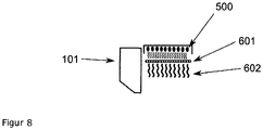
- Another possibility is the use of a fluorescent surface (601), which is illuminated by a radiation source (604) that is not necessarily monochromatic and thereby emits monochromatic radiation (602) of a specific wavelength that matches the absorption of the activator. figure 8 .
- the powder is preheated before it is applied to the existing powder surface, so that the layer does not cool down too much.
- An electrical resistance heater (507) in the coater (101) is also suitable for this powder preheating.
- all aggregates that are heated via contact heaters can also be heated indirectly via infrared radiation.
- the coater is heated with radiation when strong vibrations occur.
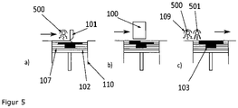
- a powder layer is produced by the coater (101) on the construction platform ( Fig. 1a ).
- the new layer can also be heated with the sintering heater (109,501).
- This layer is then printed by one (100) or more inkjet print heads (100) ( Figure 1b ) printed.
- the construction platform (102) is lowered (1d). Now the printed layer is heated with the sintering lamp (109.500) and then covered with powder again.
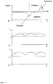
- Figure 2b shows the course of the temperature on the unprinted area.
- the use of the sintering radiation source results in heating and cooling phases that are actually constant. In the unprinted area, the temperature never reaches the sintering temperature.
- Figure 2c shows the course in the printed area.
- the fluctuations are stronger.
- the process is conducted at least in such a way that the sintering temperature is exceeded for a short time, so that part of the powder is melted and remains melted. If heated too much, all the powder in this area melts and massive distortion occurs. Excessive cooling of the printed area must also be avoided, otherwise recrystallization will set in and then all shrinkage due to the now possible power transmission will lead to geometric distortion (curling), which may make further processing impossible.
- the exemplary embodiments describe how the advantages of this radiation source can be used in the process described.
- Example 1 Device with a sintered lamp containing LED emitters of one wavelength according to the invention and having a thermal overhead lamp
- the construction process or process cycle begins with the coating of the construction platform with a layer of powder. Even during the coating by the coater (101), the powder is heated by the overhead radiator (108) if it is not optically covered by the coater (101). The sintering radiator (109), which only provides the radiation that heats the printed area well, is not switched on in this step.
- the overhead radiator (108) contains a measuring device for regulating the surface temperature of the construction area.
- the measuring device is designed as a pyrometer (508) that can determine the temperature without contact.
- the regulation must take into account that the measuring device is repeatedly shadowed by the print head (100) and the coater (101). This can be done by switching off the acquisition of measured values or by insensitive control loop parameters.
- the activator is applied by the print head (100), which is precisely tuned to the wavelength of the radiation source.
- the image that is applied to the particulate material by the print head (100) corresponds to the current mold cross-section.
- a base layer often has to be printed.
- the print head prints the full area available as a construction area.
- the third step is the sintering process.
- the sinter emitter unit (109) is switched on and guided over the construction area.
- the power of the radiation source and the speed determine the radiation power on the construction site.
- the sintered radiator (500) with one wavelength does not heat unprinted surfaces during this journey.
- the temperature of the printed areas thus rises, while unprinted areas slowly cool down due to energy loss through radiation ( Figure 3b , area II).
- the sinter emitters (109; 500) are LED emitters whose wavelength spectrum is between 0.2 ⁇ m and 0.1 ⁇ m.
- the fourth step is lowering the construction platform (102) by the thickness of a powder layer (107). During this process, the construction area for the overhead radiator (108) is free and the temperature can be readjusted. The process cycle then starts again from the beginning with the coating process.
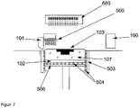
- FIG 6 describes a device that can implement the process mentioned in the example.
- the overhead radiator (108) is designed as a thermal radiation source.
- the sinter radiator is composed of small individual LED radiators (400 or 500).
- the construction container bottom and the construction platform are heated via resistance heaters (504).
- the coater (101) and the sintering radiator unit (109) are connected. This unit and the print head (100) can be moved separately over the construction area.
- figure 7 shows a special version of the example.
- the overhead spotlight is also equipped with an LED radiation source.
- Example 2 Apparatus of a sintered radiator unit that contains LED radiators with two wavelengths and has no overhead lamp
- the construction process or process cycle begins with the coating of the construction platform (102) with a layer of powder.
- the sintering radiator (501) of the unit (109) which also supplies the radiation that heats up the unprinted area, is switched on in this step and heats the powder to a base temperature below the melting temperature but above the recrystallization temperature.
- the energy supply is controlled via the power and the traversing speed.
- the generated temperature is recorded and also regulated.
- the activator is applied, which is precisely matched to the wavelength of the radiation source (500) for the printed areas.
- the image that is applied to the powder by the print head (100) corresponds to the actual shaped body.
- a base layer often has to be printed.
- the print head prints the full area available as construction area.
- the third step is the sintering process.
- the sintering unit (109) is switched on and guided over the construction area.
- the power of the radiation source and the speed determine the radiation power on the powder bed.
- the unit with two wavelengths (500,501) can influence unprinted and printed areas in a targeted manner during this journey. the The temperature of the printed areas therefore increases, while the energy loss due to radiation can be compensated for in the unprinted areas.
- the sintering unit (109) consists of LED emitters whose wavelength range is 0.2 ⁇ m to 0.1 ⁇ m.
- the fourth step is lowering the construction platform (102) by one layer thickness and is kept extremely short in this exemplary process. There is no regulation here and any delay leads to energy loss through thermal radiation. This step is therefore not included in the illustration.
Landscapes
- Engineering & Computer Science (AREA)
- Chemical & Material Sciences (AREA)
- Materials Engineering (AREA)
- Manufacturing & Machinery (AREA)
- Physics & Mathematics (AREA)
- Optics & Photonics (AREA)
- Mechanical Engineering (AREA)
- Plasma & Fusion (AREA)
- Health & Medical Sciences (AREA)
- Toxicology (AREA)
- Microelectronics & Electronic Packaging (AREA)
- General Health & Medical Sciences (AREA)
Description
Die Erfindung betrifft ein Verfahren zum Herstellen dreidimensionaler Modelle oder Formteile.The invention relates to a method for producing three-dimensional models or molded parts.
In der europäischen Patentschrift
Dieses aus verfestigtem Partikelmaterial hergestellte Objekt ist nach seiner Fertigstellung in losem Partikelmaterial eingebettet und wird anschließend davon befreit. Dies erfolgt beispielsweise mittels eines Saugers. Übrig bleiben danach die gewünschten Objekte, die dann vom Restpulver z.B. durch Abbürsten befreit werden.This object, made of solidified particulate material, is embedded in loose particulate material after its completion and is then freed from it. This is done, for example, by means of a suction cup. What remains are the desired objects, which are then freed from residual powder, e.g. by brushing.
In ähnlicher Weise arbeiten auch andere Pulver-gestützte Rapid-Prototyping-Prozesse, wie z.B. das selektive Lasersintern oder das Elektron-Beam-Sintern bei denen jeweils ebenso ein loses Partikelmaterial schichtweise ausgebracht und mit Hilfe einer gesteuerten physikalischen Energie- oder Strahlungsquelle selektiv verfestigt wird.Other powder-based rapid prototyping processes, such as selective laser sintering or electron beam sintering, also work in a similar way, each of which also uses loose particle material applied in layers and selectively solidified using a controlled source of physical energy or radiation.
Im Folgenden werden alle diese Verfahren unter dem Begriff "dreidimensionale Druckverfahren" oder "3D-Druckverfahren" zusammengefasst.In the following, all of these processes are summarized under the term "three-dimensional printing process" or "3D printing process".
Mit diesem Verfahren lassen sich verschiedene Partikelmaterialien, unter anderem auch polymere Werkstoffe, verarbeiten. Der Nachteil besteht hier jedoch darin, dass die Partikelmaterialschüttung eine gewisse Schüttdichte, die üblicherweise 60% der Feststoffdichte beträgt, nicht übersteigen kann. Die Festigkeit der gewünschten Bauteile hängt jedoch maßgeblich von der erreichten Dichte ab. Insofern wäre es hier für eine hohe Festigkeit der Bauteile erforderlich, 40% und mehr des Partikelmaterialvolumens in Form des flüssigen Binders zuzugeben. Dies ist nicht nur aufgrund des Einzeltropfeneintrages ein relativ zeitaufwändiger Prozess, sondern bedingt auch viele Prozessprobleme, die z.B. durch die zwangsläufige Schwindung der Flüssigkeitsmenge beim Verfestigen gegeben sind.Various particle materials, including polymer materials, can be processed with this method. However, the disadvantage here is that the particulate material bed cannot exceed a certain bulk density, which is usually 60% of the solid density. However, the strength of the desired components depends largely on the density achieved. In this respect it would be necessary here for a high strength of the components to add 40% or more of the particulate material volume in the form of the liquid binder. This is not only a relatively time-consuming process due to the single drop entry, but also causes many process problems, which are given, for example, by the inevitable shrinkage of the liquid volume during solidification.
In einer anderen Form des 3D-Druckes, die unter dem Begriff "High-Speed-Sintering", abgekürzt HSS, in der Fachwelt bekannt ist, erfolgt die Verfestigung des Partikelmaterials über Eintrag von Infrarotstrahlung (IR-Strahlung). Das Partikelmaterial wird dabei physikalisch über einen Aufschmelzvorgang gebunden. Hierbei wird die vergleichsweise schlechte Aufnahme von Wärmestrahlung bei farblosen Kunststoffen ausgenutzt. Diese lässt sich durch Einbringen eines IR-Akzeptors oder Absorbers in den Kunststoff um ein Vielfaches steigern. Die IR-Strahlung kann dabei über verschiedene Möglichkeiten wie z.B. eine stabförmigen IR-Strahler eingebracht werden, die gleichmäßig über das Baufeld bewegt wird (Sinterstrahler). Die Selektivität wird über das gezielte und selektive Bedrucken der jeweiligen Schicht mit einem IR-Akzeptor erreicht.In another form of 3D printing, which is known among experts under the term "high-speed sintering", abbreviated HSS, the solidification of the particle material takes place via the input of infrared radiation (IR radiation). The particle material is physically bound by a melting process. Here, the comparatively poor absorption of thermal radiation in colorless plastics is exploited. This can be increased many times over by introducing an IR acceptor or absorber into the plastic. The IR radiation can be introduced in various ways, such as a rod-shaped IR emitter, which is moved evenly over the construction area (sinter emitter). The selectivity is achieved through the targeted and selective printing of the respective layer with an IR acceptor.
An den Stellen, die bedruckt wurden, koppelt die IR-Strahlung dadurch wesentlich besser in das Partikelmaterial ein, als in den unbedruckten Bereichen. Dies führt zu einer selektiven Erwärmung in der Schicht über den Schmelzpunkt hinaus und damit zur selektiven Verfestigung in diesen Bereichen. Dieser Prozess wird z.B. in
Vom Lasersinterprozess sind verschiedene Materialien bekannt, die auch mit diesem Verfahren verarbeitet werden können. Dabei ist bei weitem das wichtigste Material Polyamid 12. Für dieses Material gibt es mehrere Hersteller. Es werden für Schichtbauverfahren ausgezeichnete Festigkeiten erzielt.Various materials are known from the laser sintering process, which can also be processed with this method. The most important material by far is polyamide 12. There are several manufacturers of this material. Excellent strengths are achieved for layer construction processes.
Das Material kann als feines Pulver bezogen werden, das direkt in dieser Qualität verarbeitet werden kann. Bedingt durch den Herstellungsprozess fallen aber hohe Kosten an, die die Kosten für Standardpolyamid um den Faktor 20-30 übertreffen können.The material can be obtained as a fine powder that can be processed directly in this quality. Due to the manufacturing process, however, high costs are incurred, which can exceed the costs for standard polyamide by a factor of 20-30.
Beim HSS-Prozess nach dem Stand der Technik wird das Pulver, genau wie beim Lasersintern, zur Verarbeitung auf eine Temperatur nahe des Schmelzpunktes des Materials gebracht. Dabei "altert" das Pulver und kann in Folgeprozessen nur noch bedingt eingesetzt werden. Es ergibt sich eine Recyclingquote, die wesentlich die Prozesskosten beeinflusst und verteuert.In the prior art HSS process, just like in laser sintering, the powder is brought to a temperature close to the melting point of the material for processing. The powder "ages" and can only be used to a limited extent in subsequent processes. The result is a recycling rate that significantly influences the process costs and makes them more expensive.
Die Genauigkeit der Bauteile wird maßgeblich durch die Prozessführung beeinflusst. Dabei ist die Homogenität der Pulverbettdichte und Temperatur im Bauraum entscheidend.The accuracy of the components is significantly influenced by the process control. The homogeneity of the powder bed density and temperature in the installation space is decisive.
Die Strahlungscharakteristik von konventionellen IR-Strahlern, die thermisch arbeiten, ist generell nicht als "monochromatisch" zu bezeichnen. Vielmehr besteht die Strahlung aus einem breiten kontinuierlichen Spektrum verschiedener Wellenlängen.The radiation characteristics of conventional IR radiators that work thermally cannot generally be described as "monochromatic". Rather, the radiation consists of a broad, continuous spectrum of different wavelengths.
Für die entstehenden Wellenlängen muss ein entsprechender Absorber gefunden werden und dem selektiv einzudruckenden Material, auch als Tinte bezeichnet, zugegeben werden. Dies schränkt oft die Farbgebung der Tinte ein. Zudem ist die Auswahl oft begrenzt, so dass generell von einem schwachen Wirkungsgrad ausgegangen werden kann.A corresponding absorber must be found for the resulting wavelengths and the material to be selectively printed, also as a called ink, to be added. This often limits the coloring of the ink. In addition, the selection is often limited, so that a generally weak degree of efficiency can be assumed.
Zudem ist die Leistung der Strahlungsquelle mit der Temperatur des Filaments oder Heizdrahtes und damit mit der emittierten Wellenlänge untrennbar verbunden. Dies beschreibt das Stefan-Boltzmann-, sowie das Wiensche Verschiebungs-Gesetz. Damit muss bei einer Skalierung der Leistung die Verschiebung der Wellenlänge mit berücksichtigt werden. Weiterhin tritt bevorzugt im fernen IR-Bereich Sekundärstrahlung auf, da Filament- bzw. Heizdraht-Umhausung wie z.B. Quarzglaskörper ebenfalls erhitzt werden und damit selbst zu Emittern werden. In genau diesem Wellenlängenbereich weisen Polymere in der Regel Absorptionsmaxima auf.In addition, the power of the radiation source is inextricably linked to the temperature of the filament or heating wire and thus to the emitted wavelength. This describes the Stefan-Boltzmann law and Wien's displacement law. This means that when scaling the power, the shift in wavelength must also be taken into account. Furthermore, secondary radiation occurs preferably in the far IR range, since filament or heating wire housings such as quartz glass bodies are also heated and thus become emitters themselves. In precisely this wavelength range, polymers usually have absorption maxima.
Im sichtbaren Bereich in dem es ausgezeichnete Absorber für unterschiedliche Wellenlänge (Farben) gibt, weisen thermisch arbeitende erhebliche IR-Anteile auf, die nicht selektiv erwärmen und damit im Sinne des Prozesses unkontrolliert das unbedruckte Pulver erhitzen. Das Ziel, beide Flächentypen - bedruckt und unbedruckt - gezielt beeinflussen zu können, kann nur eingeschränkt erreicht werden.In the visible range, in which there are excellent absorbers for different wavelengths (colors), thermally working ones have significant IR components that do not heat up selectively and thus heat the unprinted powder uncontrollably in terms of the process. The aim of being able to specifically influence both surface types - printed and unprinted - can only be achieved to a limited extent.
Jede unkontrollierte Erwärmung stellt eine Abwärmequelle dar. Solche Quellen vermindern den Wirkungsgrad der Vorrichtung und aufgrund der empfindlichen Prozessführung auch die Leistungsfähigkeit des 3D-Druckverfahrens.Any uncontrolled heating represents a source of waste heat. Such sources reduce the efficiency of the device and, due to the sensitive process control, also the performance of the 3D printing process.
Aufgabe der Erfindung ist es, ein Verfahren bereitzustellen, die die Nachteile des Standes der Technik vermindert oder ganz vermeiden hilft. Ein weitere Aufgabe der Erfindung ist es das Verfahren so zu gestalten, dass die Erwärmung der Flächentypen "bedruckt und unbedruckt" gezielt vorgenommenwerden können.The object of the invention is to provide a method which reduces the disadvantages of the prior art or helps to avoid them entirely. A further object of the invention is to design the method in such a way that the surface types "printed and unprinted" can be heated in a targeted manner.
Diese Aufgabe wird erfindungsgemäß gelöst durch ein Verfahren zum Herstellen von 3D-Formteilen, wobei partikelförmiges Baumaterial in einer definierten Schicht mittels Beschichter auf ein Baufeld aufgetragen wird, selektiv eine oder mehrere Flüssigkeiten oder Partikelmaterial eines oder mehrerer Absorber aufgebracht werden, mit geeigneten Mitteln ein Energieeintrag erfolgt und so eine selektive Verfestigung der mit Absorber bedruckten Bereiche bei einer Verfestigungstemperatur oder Sintertemperatur oberhalb der Schmelztemperatur des Pulvers erfolgt, das Baufeld um eine Schichtstärke abgesenkt oder der Beschichter um eine Schichtstärke angehoben wird, diese Schritte wiederholt werden bis das gewünschte 3D-Formteil erzeugt ist, dadurch gekennzeichnet, dass der Energieeintrag von bedruckten durch einen Sinterstrahler mittels LED in einem engen Wellenlängenspektrum mit der Breite von 0,2 µm bis 0,1 µm erfolgt.This object is achieved by a method for producing 3D molded parts, wherein particulate building material in a a defined layer is applied to a construction site by means of a coater, one or more liquids or particle material from one or more absorbers are selectively applied, energy is introduced using suitable means and thus selective solidification of the areas printed with absorber at a solidification temperature or sintering temperature above the melting temperature of the powder takes place, the construction area is lowered by one layer thickness or the coater is raised by one layer thickness, these steps are repeated until the desired 3D molded part is produced, characterized in that the energy input from printed by a sintering radiator using LEDs in a narrow wavelength spectrum with the width from 0.2 µm to 0.1 µm.
Erfindungsgemäß wird diese Aufgabe weiterhin dadurch gelöst, dass LED Strahlungsquellen als Sinterstrahler eingesetzt werden, die eine als im wesentlichen monochromatisch zu charakterisierende Wellenlänge aufweisen. Dies können spezielle LED-Lichtquellen sein. Diese Strahlertypen weisen eine sehr enge spektrale Verteilung auf. Entsteht beim Strahlungserzeugungsprozess zusätzlich Wärmestrahlung, kann diese über Kühlung reduziert werden.According to the invention, this object is also achieved in that LED radiation sources are used as sintered radiators, which have a wavelength that can be characterized as essentially monochromatic. These can be special LED light sources. These radiator types have a very narrow spectral distribution. If additional thermal radiation occurs during the radiation generation process, this can be reduced by cooling.
Ebenfalls Teil der Offenbarung, aber nicht Teil der vorliegenden Erfindung, ist die Verwendung einer mittels nicht zwingend monochromatischen Lichtquelle beleuchteten Fläche, welche durch ein fluoreszierendes Material gekennzeichnet ist, das dann monochromatische Strahlung emittiert. Dies hat den Vorteil, gezielt Wellenlängen einzusetzen, die mittels marktüblicher monochromatischer Lichtquellen nicht zugänglich und/oder deren Einsatz nicht praktikabel ist. Des Weiteren kann dadurch eine bessere Gleichmäßigkeit der Intensität der abgegebenen Strahlung bezogen auf die Fläche erreicht werden.Also part of the disclosure, but not part of the present invention, is the use of a surface illuminated by a light source which is not necessarily monochromatic and which is characterized by a fluorescent material which then emits monochromatic radiation. This has the advantage of using wavelengths in a targeted manner that are not accessible using commercially available monochromatic light sources and/or whose use is not practicable. Furthermore, better uniformity of the intensity of the emitted radiation can be achieved in relation to the surface.
Aufgrund des Einsatzes von LED Strahlungsquellen mit einem engen Wellenlängenspektrum erhöht sich weiterhin die Auswahl an für die Strahlung transparenter Materialien. Dies schließt marktübliche Materialien mit ein, die als Diffusor eingesetzt werden können, um damit die Strahlungsgleichmäßigkeit ebenfalls zu maximieren.Due to the use of LED radiation sources with a narrow wavelength spectrum, the choice of materials that are transparent to the radiation continues to increase. This excludes standard market Materials that can be used as diffusers to maximize radiation uniformity as well.
Die Beleuchtung mit höherenergetischer Strahlung nach der Offenbarung ist dadurch zugänglich, was die Eindringtiefe in die Pulverschicht erhöht. Der Verbund der einzelnen im Schichtaufbauverfahren teilgeschmolzenen Flächen lässt sich somit steigern, was der Festigkeit der herzustellenden Formteile zu Gute kommt Der Einsatz beschriebener Strahlungsquellen ermöglicht nicht nur die Reduzierung des Strahlerabstandes zur Fläche, sondern auch der Strahlergröße wodurch sich kompaktere Maschinengeometrien realisieren lassen und sich die Energieeffizienz in erheblichen Maße steigernlässt.The illumination with higher energy radiation according to the disclosure is thereby accessible, which increases the depth of penetration into the powder layer. The bond between the individual surfaces that are partially melted in the layering process can thus be increased, which benefits the strength of the molded parts to be produced. The use of the radiation sources described not only enables the distance between the emitter and the surface to be reduced, but also the size of the emitter, which means that more compact machine geometries can be implemented and energy efficiency increased can be increased to a considerable extent.
Eine bei konventionellen Strahlungsquellen im sichtbaren bzw. InfrarotBereich auftretende Aufheiz- bzw. Abkühlzeit der Strahler entfällt, womit sich der Schichtaufbauprozess erheblich beschleunigen ließe. Eine stark erhöhte Alterung konventioneller Strahlungsquellen aufgrund häufiger Aufheiz- und Abkühlprozesse entfällt ebenfalls.The heat-up and cool-down time of the emitters that occurs with conventional radiation sources in the visible or infrared range is eliminated, which means that the layer build-up process can be significantly accelerated. A greatly increased aging of conventional radiation sources due to frequent heating and cooling processes is also eliminated.
Aufgrund der wegfallenden Reaktionsträgheit ist ein selektives An- bzw. Abschalten der Strahlungsquellen während einer Überfahrt über die zu bestrahlende Fläche möglich, z.B. nach einem Matrixverfahren.Due to the lack of reaction inertia, the radiation sources can be switched on and off selectively while crossing the area to be irradiated, e.g. using a matrix method.
Damit können die Temperaturen der Flächen gezielt eingestellt werden. Die Abwärmeverluste werden begrenzt und damit der Gesamtwirkungsgrad der Vorrichtung erhöht. Dies kann insbesondere bei Maschinen mit temperaturempfindlichen Komponenten von Vorteil sein, da der Maschinenraum an sich kälter gehalten werden kann.This allows the temperatures of the surfaces to be set specifically. The waste heat losses are limited and thus the overall efficiency of the device is increased. This can be particularly advantageous for machines with temperature-sensitive components, since the machine room itself can be kept colder.
Unter Betrachtung von Sicherheitsaspekten wie Brandschutz sind die erwähnten Verbesserungen aufgrund der erheblich reduzierten Hitzeentwicklung ebenfalls von großem Vorteil. Die Alterung bzw. Degradierung des verwendeten Partikelmaterials aufgrund hoher Temperaturen lässt sich außerdem an nicht zu verfestigenden Flächen weiter reduzieren und die Entnahme der verfestigten Stellen nach dem Abkühlprozess vereinfachen.When considering safety aspects such as fire protection, the improvements mentioned are also of great advantage due to the significantly reduced heat generation. The aging or degradation of the particle material used due to high temperatures can also be detected on surfaces that are not to be consolidated further reduce and simplify the removal of the solidified areas after the cooling process.
Da die Strahlerleistung nicht mit der Wellenlänge gekoppelt ist, kann die Leistung der Vorrichtung problemlos gesteigert werden. Der Prozess an sich bleibt davon unberührt.Since the emitter power is not coupled to the wavelength, the power of the device can be easily increased. The process itself remains unaffected.
Einige der beschriebenen Vorteile lassen sich ebenfalls durch den Einsatz nicht-monochromatischer Lichtquellen erreichen, sofern diese einen genügend engen Bereich aufweisen und bei höheren Temperaturen als handelsüblich betrieben werden können. Dadurch reduziert sich die Bandbreite der emittierten Strahlung, wie dem Planckschen Strahlungsgesetz entnommen werden kann. Eine geringe Größe würde eine gleichmäßigere Bestrahlung ermöglichen und ebenfalls das Aussparen nicht zu verfestigender Flächen erlauben, insbesondere weil sich An- und Abschaltzeiten mit steigender Emittertemperatur verkürzen.Some of the advantages described can also be achieved by using non-monochromatic light sources, provided they have a sufficiently narrow range and can be operated at higher temperatures than are commercially available. This reduces the bandwidth of the emitted radiation, as can be seen from Planck's radiation law. A small size would enable more uniform irradiation and also allow areas not to be solidified to be left out, in particular because switch-on and switch-off times become shorter as the emitter temperature rises.
Die geringere Verlustleistung und Größe der beschriebenen Strahler ermöglicht eine verschachtelte Bauweise von Emittern verschiedener Wellenlängen, ohne die Gleichmäßigkeit der Strahlungsintensität bezogen auf die Fläche aufgeben zu müssen. Ein Aufbau mit Emittern auch dreier verschiedener Wellenlängen ist möglich.The lower power dissipation and size of the emitters described enable a nested construction of emitters of different wavelengths without having to give up the uniformity of the radiation intensity in relation to the area. A structure with emitters of three different wavelengths is also possible.
Mit der Schmalbandigkeit der Emitter können in einem Aspekt der Erfindung selektiv einzelne Bestandteile des Aktivators gezielt angeregt werden, insbesondere die Trägerflüssigkeit. Dadurch lassen sich Flüssigkeitsanteile unmittelbar nach Auftrag evaporieren, sodass diese nicht im herzustellenden Formteil zurück bleiben.With the narrow-band nature of the emitters, individual components of the activator, in particular the carrier liquid, can be selectively excited in one aspect of the invention. As a result, liquid components can be evaporated immediately after application so that they do not remain in the molded part to be produced.
Die wesentlich zielgerichtetere Temperatursteuerung nach der Offenbarung ermöglicht bei selektivem Flüssigkeitsauftrag ein und desselben Absorbers, durch die aufgetragene Menge gesteuert, unterschiedliche Temperaturen zu erzielen, sodass bei gleichzeitiger Verwendung zweier verschiedener Partikelmaterialien mit unterschiedlichen Sintertemperaturen in einer Mischung gezielt ein Partikelmaterialtypteilgeschmolzen werden kann, wobei der andere unverändert bleibt. Dadurch lässt sich über die Absorbermenge die Formkörpereigenschaft gezielt beeinflussen.The significantly more targeted temperature control according to the disclosure makes it possible to achieve different temperatures when selectively applying liquid to one and the same absorber, controlled by the amount applied, so that when two different particle materials with different sintering temperatures are used in a mixture at the same time Particulate type part can be melted leaving the other untouched. As a result, the properties of the shaped body can be influenced in a targeted manner via the amount of absorber.
Im Folgenden werden einige Begriffe der Erfindung näher erläutert. "Formkörper" oder "Bauteil" im Sinne der Erfindung sind alles mittels des erfindungsgemäßen Verfahrens hergestellte dreidimensionale Objekte, die eine Formfestigkeit aufweisen.Some terms of the invention are explained in more detail below. "Moulding" or "component" within the meaning of the invention are all three-dimensional objects produced by means of the method according to the invention, which have a dimensional stability.
"Bauraum" ist der geometrische Ort in dem die Partikelmaterialschüttung während des Bauprozesses durch wiederholtes Beschichten mit Partikelmaterial wächst oder durch den die Schüttung bei kontinuierlichen Prinzipien hindurchläuft. Im Allgemeinen wird der Bauraum durch einen Boden, die Bauplattform, durch Wände und eine offene Deckfläche, die Bauebene, begrenzt. Bei kontinuierlichen Prinzipien existieren meist ein Förderband und begrenzende Seitenwände."Build space" is the locus in which the particulate material bed grows during the build process by repeated coating of particulate material, or through which the bed passes in continuous principles. In general, the construction space is delimited by a floor, the construction platform, by walls and an open top surface, the construction level. With continuous principles, there is usually a conveyor belt and delimiting side walls.
Die "Aufheizphase" kennzeichnet ein Erwärmen der Vorrichtung zu Beginn des Verfahrens. Die Aufheizphase ist abgeschlossen, wenn die Solltemperatur der Vorrichtung stationär wird.The "warm-up phase" denotes warming up of the device at the beginning of the process. The warm-up phase is complete when the set temperature of the device becomes steady.
Die "Abkühlphase" ist mindestens solange andauernd, bis die Temperatur so niedrig ist, dass die Bauteile keine merklichen plastischen Deformationen beim Entnehmen aus dem Bauraum erfahren.The “cooling phase” lasts at least until the temperature is so low that the components do not experience any noticeable plastic deformation when they are removed from the installation space.
Als "Partikelmaterialien" können alle für den Pulver-basierten 3D Druck bekannten Materialien verwendet werden, insbesondere Polymere, Keramiken und Metalle. Möglich sind auch Partikelmaterialien aus Materialgemischen oder Composite aus unterschiedlichen Materialien, weiterhin Partikelmaterialien auf Basis von nachwachsenden Rohstoffen wie beispielsweise Cellulosefasern oder Holzpulver. Das Partikelmaterial ist vorzugsweise ein trocken frei fließendes Pulver, es kann aber auch ein kohäsives schnittfestes Pulver oder eine partikelbeladene Flüssigkeit verwendet werden. In dieser Schrift werden Partikelmaterial und Pulver synonym verwendet.All materials known for powder-based 3D printing can be used as "particle materials", in particular polymers, ceramics and metals. Particulate materials from material mixtures or composites from different materials are also possible, as well as particle materials based on renewable raw materials such as cellulose fibers or wood powder. The particulate material is preferably a dry, free-flowing powder, but can also be a cohesive, cut-resistant powder or a particulate-laden liquid be used. In this document, particle material and powder are used synonymously.
Der "Aktivator" oder "Absorber" ist im Sinne dieser Erfindung ein mit einem Tintenstrahldruckkopf oder mit einer anderen matrixartig arbeitenden Vorrichtung verarbeitbares Medium, das die Absorption von Strahlung zur lokalen Erwärmung des Pulvers fördert. Der "Absorber" kann auch partikelförmig sein wie beispielsweise schwarzer Toner. Absorber können gleichmäßig oder in unterschiedlichen Mengen selektiv aufgebracht werden. Bei Aufbringen in unterschiedlichen Mengen kann man somit die Festigkeit in dem Baumaterial steuern und selektiv unterschiedliche Festigkeiten erzielen, beispielsweise in dem herzustellenden Formteil. Der Bereich der Festigkeit reicht von einer Festigkeit wie im Bauteil selbst bis zu eine Festigkeit, die nur unwesentlich über der des Baumaterials ohne Absorberaufdruck liegt. Damit wird es möglich eine Temperaturregulierung in dem Baufeld/Bauraum vorzunehmen und wenn gewünscht den Mantel, der der Temperaturregulierung dient, auch leicht um das hergestellte Bauteil zu entfernen.The “activator” or “absorber” in the context of this invention is a medium that can be processed with an inkjet printhead or with another device that works in a matrix-like manner, which medium promotes the absorption of radiation for local heating of the powder. The "absorber" can also be particulate, such as black toner. Absorbers can be applied evenly or selectively in varying amounts. When applied in different amounts, one can thus control the strength in the building material and selectively achieve different strengths, for example in the molded part to be produced. The strength ranges from a strength as in the component itself to a strength that is only slightly higher than that of the building material without an absorber print. This makes it possible to regulate the temperature in the construction area/construction space and, if desired, to easily remove the jacket, which serves to regulate the temperature, in order to remove the component produced.
"IR-Erwärmung" bedeutet in dieser Schrift speziell eine Bestrahlung des Baufeldes mit einem IR-Strahler. Dabei kann der Strahler ebenso statisch sein oder mit einer Verfahreinheit über das Baufeld bewegt werden. Durch den Einsatz des Aktivators führt die IR-Erwärmung im Baufeld zu unterschiedlich starken Temperaturanstiegen.In this document, “IR heating” specifically means irradiating the construction area with an IR radiator. The emitter can also be static or moved over the construction site with a traversing unit. By using the activator, the IR heating in the construction area leads to temperature increases of different magnitudes.
"Strahlungserwärmung" verallgemeinert den Begriff IR- Erwärmung. Durch die Absorption von Strahlung beliebiger Wellenlänge kann sich ein Festkörper oder eine Flüssigkeit erwärmen."Radiant heating" generalizes the term IR heating. A solid or liquid can heat up by absorbing radiation of any wavelength.
Mit "Flächentyp" wird die Differenzierung zwischen mit Absorber unbedruckten und bedruckten Bereichen zum Ausdruck gebracht."Area type" expresses the differentiation between areas that are unprinted with absorber and areas that are printed.
Ein "IR-Strahler" ist eine Quelle von infraroter Strahlung. Dabei werden meist glühende Drähte in Quarz oder Keramikgehäusen zur Erzeugung der Strahlung benutzt. Je nach eingesetzten Materialien ergeben sich unterschiedliche Wellenlängen der Strahlung. Die Wellenlänge ist bei diesem Strahlertyp zusätzlich abhängig von der Leistung.An "IR emitter" is a source of infrared radiation. Usually glowing wires in quartz or ceramic housings are used to generate the radiation. Depending on the materials used, there are different wavelengths of radiation. With this type of radiator, the wavelength also depends on the power.
Eine "Strahlungsquelle" gibt generell Strahlung mit einer bestimmten Wellenlänge oder einen Wellenlängenbereich ab. Eine Strahlungsquelle mit nahezu monochromatischer Strahlung wird als "monochromatischer Strahler" bezeichnet. Eine Strahlungsquelle wird auch als "Emitter" bezeichnet. Im Sinne der Erfindung werden Strahler mit einem engen Wellenlängenbereich verwendet, wobei ein Bereich von 0,2 bis 0,1 µm ist.A "radiation source" generally emits radiation at a particular wavelength or range of wavelengths. A radiation source with almost monochromatic radiation is referred to as a "monochromatic radiator". A radiation source is also referred to as an "emitter". According to the invention, radiators with a narrow wavelength range are used, with a range from 0.2 to 0.1 μm.
Eine "Overheadstrahler" im Sinne der Erfindung ist eine Strahlungsquelle die über dem Baufeld angebracht ist. Sie ist stationär kann aber in ihrer Strahlungsleistung reguliert werden. Sie sorgt im Wesentlichen für eine flächige nicht selektive Erwärmung.An "overhead radiator" within the meaning of the invention is a radiation source that is mounted above the construction site. It is stationary but can be regulated in its radiation power. Essentially, it ensures that the area is heated non-selectively.
Die "Sinterstrahler" ist eine Strahlungsquelle, die das Prozesspulver über seine Sintertemperatur erhitzt. Sie kann stationär sein. In bevorzugten Ausführungen wird sie aber über das Baufeld bewegt. Im Sinne dieser Erfindung ist der Sinterstrahler als monochromatischer Strahler ausgeführt.The "sinter heater" is a radiation source that heats the process powder above its sintering temperature. It can be stationary. In preferred embodiments, however, it is moved over the construction field. In terms of this invention, the sintering radiator is designed as a monochromatic radiator.
"Sintern" ist der Begriff für das partielle Zusammenwachsen der Partikel im Pulver. Mit dem Sintern verbunden ist bei diesem System der Aufbau von Festigkeit."Sintering" is the term for the partial coalescence of the particles in the powder. With this system, sintering is associated with the build-up of strength.
Der Begriff "Sinterfenster" bezeichnet die Differenz der Temperatur des beim ersten Aufheizen des Pulvers auftretenden Schmelzpunktes und dem bei anschließendem Abkühlen auftretenden Erstarrungspunktes.The term "sintering window" refers to the temperature difference between the melting point occurring when the powder is first heated and the solidification point occurring during subsequent cooling.
Die "Sintertemperatur" ist die Temperatur ab der das Pulver erstmalig aufschmilzt und sich verbindet.The "sintering temperature" is the temperature at which the powder melts and connects for the first time.
Unterhalb der "Rekristallisationstemperatur" wird einmal aufgeschmolzenes Pulver wieder fest und schwindet deutlich.Below the "recrystallization temperature", once the powder has melted, it solidifies again and clearly shrinks.
Die "Packungsdichte" beschreibt die Ausfüllung des geometrischen Raumes durch Feststoff. Sie hängt von der Natur des Partikelmaterials und der Auftragsvorrichtung ab und ist eine wichtige Ausgangsgröße für den Sinterprozess. In den meisten Fällen beträgt die Packungsdichte nicht 100% und es befinden sich Hohlräume zwischen den Partikeln des Partikelmaterials und eine gewisse Porosität ist beim Aufbringen des Partikelmaterials und im fertigen Formteil vorhanden.The "packing density" describes the filling of the geometric space with solids. It depends on the nature of the particle material and the application device and is an important starting point for the sintering process. In most cases the packing density is not 100% and there are voids between the particles of the particulate material and some porosity is present in the application of the particulate material and in the final molded part.
Der Begriff "Schwindung" bezeichnet den Vorgang der geometrischen Verkürzung einer Abmessung eines geometrischen Körpers infolge eines physikalischen Vorganges. Beispielhaft ist das Sintern von nicht ideal gepackten Pulvern ein Vorgang der eine Schwindung relativ auf das Anfangsvolumen mit sich bringt. Einer Schwindung kann eine Richtung zugeordnet werden.The term "shrinkage" refers to the process of geometric shortening of a dimension of a geometric body as a result of a physical process. For example, the sintering of non-ideally packed powders is a process that involves shrinkage relative to the initial volume. A direction can be assigned to a shrinkage.
"Deformation" tritt auf, wenn der Körper bei einem physikalischen Prozess eine ungleichmäßige Schwindung erfährt. Diese Deformation kann reversibel oder irreversibel sein. Die Deformation wird oft auf die globale Geometrie des Bauteils bezogen."Deformation" occurs when the body undergoes non-uniform shrinkage in a physical process. This deformation can be reversible or irreversible. The deformation is often related to the global geometry of the part.
Als "Curling" wird in dieser Schrift ein Effekt bezeichnet, der vom schichtweisen Vorgehen bei der beschriebenen Erfindung kommt. Dabei sind jeweils kurz nacheinander erzeugte Schichten einer unterschiedlichen Schwindung ausgesetzt. Durch physikalische Effekte deformiert sich der Verbund dann in einer Richtung, die nicht mit der Richtung der Schwindung zusammenfällt.In this document, "curling" refers to an effect that comes from the layered procedure in the described invention. In this case, layers produced in quick succession are exposed to different shrinkage. As a result of physical effects, the composite then deforms in a direction that does not coincide with the direction of shrinkage.
Der "Grauwert" bezeichnet die in das Pulver eingedruckte Aktivatormenge. Dabei können erfindungsgemäß verschiedene Grauwerte auf das Baufeld aufgedruckt werden, um unterschiedliche Erwärmungsgrade zu erzielen.The "grey value" refers to the amount of activator imprinted into the powder. According to the invention, different gray values can be printed onto the construction field in order to achieve different degrees of heating.
Als "Partikelmaterialien" oder "partikelförmige Baumaterialien" oder "Baumaterialien" können alle für den Pulver-basierten 3D Druck bekannten Materialien verwendet werden, insbesondere Polymere, Keramiken und Metalle. Das Partikelmaterial ist vorzugsweise ein trocken frei fließendes Pulver, es kann aber auch ein kohäsives schnittfestes Pulver oder eine partikelbeladene Flüssigkeit verwendet werden. In dieser Schrift werden Partikelmaterial und Pulver synonym verwendet."Particulate materials" or "particulate build materials" or "build materials" can all be used for powder-based 3D printing known materials are used, in particular polymers, ceramics and metals. The particulate material is preferably a dry, free-flowing powder, but a cohesive, cut-resistant powder or a particulate-laden liquid can also be used. In this document, particle material and powder are used synonymously.
Der "Partikelmaterialauftrag" ist der Vorgang bei dem eine definierte Schicht aus Pulver erzeugt wird. Dies kann entweder auf der Bauplattform oder auf einer geneigten Ebene relativ zu einem Förderband bei kontinuierlichen Prinzipen erfolgen. Der Partikelmaterialauftrag wird im Weiteren auch "Beschichtung" oder "Recoaten" genannt.The "particle material application" is the process in which a defined layer of powder is created. This can be done either on the build platform or on an inclined plane relative to a conveyor for continuous principles. The particle material application is also referred to below as "coating" or "recoating".
"Selektiver Flüssigkeitsauftrag" kann im Sinne der Erfindung nach jedem Partikelmaterialauftrag erfolgen oder je nach den Erfordernissen des Formkörpers und zur Optimierung der Formkörperherstellung auch unregelmäßig, beispielsweise mehrfach bezogen auf einen Partikelmaterialauftrag, erfolgen. Dabei wird ein Schnittbild durch den gewünschten Körper aufgedruckt. Im Zusammenhang mit der vorliegenden Erfindung kann der Absorber in einer Flüssigkeit oder Tinte als Träger- oder Druckmittel aufgenommen, dispergiert oder gelöst sein.According to the invention, "selective application of liquid" can take place after each particle material application or, depending on the requirements of the shaped body and to optimize the production of the shaped body, also irregularly, for example several times based on a particle material application. A sectional image is printed through the desired body. In the context of the present invention, the absorber can be incorporated, dispersed or dissolved in a liquid or ink as a carrier or printing medium.
Als "Vorrichtung" zum Durchführen des erfindungsgemäßen Verfahrens kann jede bekannte 3D-Druckvorrichtung verwendet werden, die die erforderlichen Bauteile beinhaltet. Übliche Komponenten beinhalten Beschichter, Baufeld, Mittel zum Verfahren des Baufeldes oder anderer Bauteile bei kontinuierlichen Verfahren, Dosiervorrichtungen und Wärme- und Bestrahlungsmittel und andere dem Fachmann bekannte Bauteile, die deshalb hier nicht näher ausgeführt werden.Any known 3D printing device that contains the necessary components can be used as the "device" for carrying out the method according to the invention. Common components include coater, build area, means for moving the build area or other components in continuous processes, dosing devices and heating and irradiation means and other components known to those skilled in the art, which are therefore not detailed here.
Die "Absorption" bezeichnet die Aufnahme der Wärmeenergie von Strahlung durch das Baumaterial. Die Absorption ist abhängig vom Pulvertyp und der Wellenlänge der Strahlung."Absorption" refers to the absorption of thermal energy from radiation by the building material. The absorption depends on the type of powder and the wavelength of the radiation.
Der "Träger" bezeichnet das Medium in dem der eigentliche Absorber vorhanden ist. Es kann sich um ein Öl, ein Lösemittel oder allgemein um eine Flüssigkeit handeln. Hierzu wird auch auf den Begriff "selektiver Flüssigkeitsauftrag" verwiesen.The "carrier" refers to the medium in which the actual absorber is present. It can be an oil, a solvent or anything in general trade a liquid. In this regard, reference is also made to the term "selective application of liquid".
"Strahlungsinduzierte Erwärmung" bedeutet im Folgenden eine Bestrahlung des Baufeldes mit festen oder beweglichen Strahlungsquellen. Der Absorber ist auf die Strahlungsart abgestimmt und vorzugsweise optimiert. Dabei soll es zu einer unterschiedlich starken Erwärmung von "aktiviertem" und nicht "aktiviertem" Pulver kommen. "Aktiviert" bedeutet, dass durch den Absorbereindruck die Temperatur in diesen Bereichen erhöht wird im Vergleich zu den übrigen Bereichen im Bauraum. "Basistemperatur" im Sinne der Erfindung ist die Temperatur, die im Bauraum auf der Oberfläche des Partikelmaterials und in dem aufgedruckten Partikelmaterial mit geeigneten Mitteln, z.B. einem IR-Strahler, eingestellt wird. Dabei wird die Basistemperatur so gewählt, dass sie bezogen auf das Partikelmaterial und in Zusammenspiel mit dem Absorber geeignet ist, um das selektive Verfestigen mit positiven Materialeigenschaften zu erreichen.In the following, "radiation-induced heating" means irradiation of the construction area with fixed or mobile radiation sources. The absorber is matched to the type of radiation and preferably optimized. This should result in heating of “activated” and non-“activated” powder to differing degrees. "Activated" means that the temperature in these areas is increased by the absorber impression compared to the other areas in the installation space. "Basic temperature" within the meaning of the invention is the temperature that is set in the installation space on the surface of the particle material and in the printed particle material with suitable means, e.g. an IR radiator. The base temperature is selected in such a way that it is suitable in relation to the particle material and in interaction with the absorber in order to achieve selective solidification with positive material properties.
Das Baumaterial wird immer in einer "definierten Schicht" oder "Schichtstärke" aufgebracht, die je nach Baumaterial und Verfahrensbedingungen individuell eingestellt wird. Sie beträgt beispielsweise 0,05 bis 0,5 mm, vorzugsweise 0,1 bis 0,3 mm.The building material is always applied in a "defined layer" or "layer thickness", which is set individually depending on the building material and process conditions. It is, for example, 0.05 to 0.5 mm, preferably 0.1 to 0.3 mm.
Die der Erfindung zugrunde liegende Aufgabe wird durch ein Verfahren gelöst, welches dadurch gekennzeichnet ist, dass die im wesentlichen monochromatische Strahlung ausgewählt wird oder erzeugt wird durch eine oder mehrere LED-Lichtquellen in einem engen Wellenlängenspektrum mit einer Breite von 0,2 µm bis 0,1 µm.The object on which the invention is based is achieved by a method which is characterized in that the essentially monochromatic radiation is selected or generated by one or more LED light sources in a narrow wavelength spectrum with a width of 0.2 μm to 0. 1 µm.
Die Temperaturführung in dem erfindungsgemäßen Verfahren kann je nach Anforderungen und konstruktiven Merkmalen der verwendeten 3D-Druckvorrichutng in unterschiedlicher Weise ausgeführt werden. So kann ein Overheadstrahler oder/und ein Sinterstrahler zum Einsatz kommen. Andererseits kann das Verfahren dadurch gekennzeichnet sein, dass ein Overheadstrahler für eine Grunderwärmung und ein Sinterstrahler für die Erwärmung der bedruckten Flächen über die Schmelztemperatur verwendet werden.The temperature control in the method according to the invention can be carried out in different ways depending on the requirements and design features of the 3D printing device used. An overhead radiator and/or a sinter radiator can be used. On the other hand, the method can be characterized in that an overhead heater is used for basic heating and a sinter heater for heating the printed areas above the melting temperature.
Vorzugsweise wird das Verfahren so durchgeführt, dass ein Sinterstrahler, der eine Wellenlänge für die Erwärmung der bedruckten Flächen über die Schmelztemperatur aufweist, und der eine Wellenlänge für die Erwärmung der unbedruckten Flächen über die Rekristallisationstemperatur aufweist, verwendet wird, wobei vorzugsweise kein statischer Overheadstrahler verwendet wird oder dass ein statischer Overheadstrahler, der eine Wellenlänge für die Erwärmung der bedruckten Flächen über die Schmelztemperatur aufweist, und der eine Wellenlänge für die Erwärmung der unbedruckten Flächen über die Rekristallisationstemperatur aufweist, verwendet wird, wobei vorzugsweise kein beweglicher Sinterstrahler verwendet wird.The method is preferably carried out in such a way that a sintering radiator is used which has a wavelength for heating the printed areas above the melting temperature and which has a wavelength for heating the unprinted areas above the recrystallization temperature, with preferably no static overhead radiator being used or that a static overhead radiator having a wavelength for heating the printed areas above the melting temperature and having a wavelength for heating the unprinted areas above the recrystallization temperature is used, preferably without using a moving sintering radiator.
Im weiteren kann das Verfahren dadurch gekennzeichnet sein, dass die Leistung der jeweiligen Elemente verstellt werden kann und eine Regelung der jeweiligen Erwärmung erfolgen kann.Furthermore, the method can be characterized in that the power of the respective elements can be adjusted and the respective heating can be regulated.
In einem weiteren Aspekt kann das Verfahren dadurch gekennzeichnet sein, dass zur gezielten Erwärmung von bedruckten und unbedruckten Flächen selektives An- bzw. Abschalten der Strahlungsquellen während einer Überfahrt über die Baufläche vorgenommen wird oder/und dass selektives An- bzw. Abschalten von stationären Strahlungsquellen vorgenommen wird.In a further aspect, the method can be characterized in that the radiation sources are selectively switched on and off during a passage over the construction area for the targeted heating of printed and unprinted areas and/or that stationary radiation sources are selectively switched on and off is made.
Als Absorber kann jedes geeignete und mit den anderen Verfahrensbedingungen komnpatible Absorbermittel, -gemisch alleine oder in Kombination mit einem Tragermittel oder weitern Bestandteilen verwendet werden. Vorzugsweise ist der Absorber eine Flüssigkeit, vorzugsweise eine ölbasierte Tinte, die Kohlenstoffpartikel enthält, z.B. XAAR IK821.Any suitable absorber agent or mixture that is compatible with the other process conditions can be used as the absorber, alone or in combination with a carrier agent or other components. Preferably the absorber is a liquid, preferably an oil based ink containing carbon particles, for example XAAR IK821.
Als ein partikelförmiges Baumaterial wird ein mit den übrigen Komponenten verwendbares Maumaterial verwendet, vorzugsweise mit einer mittleren Körngröße von 50 - 60 µm, vorzugsweise 55 µm, einer Schmelztemperatur von 180 - 190 °C, vorzugsweise von 186 °C und/oder einer Rekristallisationstemperatur von 140 - 150 °C, vorzugsweise von 145 °C verwendet wird, vorzugsweise ein Polyamid12, mehr bevorzugt PA2200® oder Vestosint1115® .A masonry material that can be used with the other components is used as a particulate building material, preferably with an average grain size of 50-60 μm, preferably 55 μm, a melting temperature of 180-190 °C, preferably 186 °C and/or a recrystallization temperature of 140 - 150°C, preferably 145°C, preferably a polyamide 12, more preferably PA2200 ® or Vestosint 1115 ® .
Bei Durchführung des Verfahrens findet eine Erhitzung derart statt, dass nur die mit Absorber bedruckten Bereiche sich durch partielles Schmelzen oder Sintern verbinden, wobei das Baumaterial als Pulver oder als Dispersion verwendet wird, oder/und wobei das Baufeld und/oder das aufgetragene Baumaterial temperiert werden, oder/und wobei der Absorber strahlungsabsorbierende Bestandteile, Weichmacher für das partikelförmige Baumaterial oder/und ein oder mehrere Stoffe zur Störung der Rekristallisierung umfasst.When the method is carried out, heating takes place in such a way that only the areas printed with absorber connect through partial melting or sintering, with the building material being used as a powder or as a dispersion, and/or with the building area and/or the building material applied being tempered , or/and wherein the absorber comprises radiation-absorbing components, plasticizers for the particulate building material and/or one or more substances to disrupt recrystallization.
Im weiteren ist das Verfahren dadurch gekennzeichnet, dass die Menge des oder der Absorber über Graustufen des Druckkopfes oder Ditheringverfahren reguliert wird.Furthermore, the method is characterized in that the amount of the absorber or absorbers is regulated via gray scales of the print head or dithering processes.
Das selektiv aufgebrachte Mittel wird mit geeigneten Mitteln aufgetragen und in einer geeigneten und notwendigen Menge, wobei vorzugsweise die Flüssigkeit mittels eines oder mehrerer Druckköpfe selektiv aufgebracht wird, vorzugsweise wobei der oder die Druckköpfe in ihrer Tropfenmasse einstellbar sind, oder/und wobei der oder die Druckköpfe die Flüssigkeit in einer oder in beiden Verfahrrichtungen selektiv aufbringen, oder/und wobei das partikelförmige Baumaterial selektiv verfestigt, vorzugsweise selektiv verfestigt und gesintert wird.The selectively applied agent is applied by suitable means and in a suitable and necessary amount, preferably the Liquid is applied selectively by means of one or more print heads, preferably with the drop mass of the print head or heads being adjustable, and/or with the print head or heads applying the liquid selectively in one or both directions of travel, and/or with the particulate building material being selectively solidified , Preferably selectively solidified and sintered.
Im Folgenden wird die Erfindung in ihren verschiedenen Aspekten beschrieben.In the following, the invention is described in its various aspects.
Die zentrale Aufgabenstellung die jeweiligen Flächentypen gezielt zu erwärmen wird vorzugsweise über den Einsatz von monochromatischen Strahlungsquellen erreicht.The central task of heating the respective surface types in a targeted manner is preferably achieved by using monochromatic radiation sources.
Das Verfahren nach dem Stand der Technik besteht aus den Schritten Schichterzeugen, Bedrucken, Belichten mit Strahlung und Absenken. Der erste Schritt ist analog zur Schichtbildung beim bekannten pulverbasierten-3D-Drucken. Pulver wird vor eine Klinge gebracht, auf eine Bauplattform aufgebracht und mit der Klinge glattgestrichen. Die Positionen der Bauplattform bei zwei aufeinanderfolgenden Beschichtungsvorgängen bestimmt dabei die Schichtstärke.The prior art method consists of the steps of layering, printing, exposure to radiation and sinking. The first step is analogous to the layer formation in the well-known powder-based 3D printing. Powder is brought in front of a blade, applied to a construction platform and smoothed out with the blade. The position of the construction platform during two consecutive coating processes determines the layer thickness.
Im Anschluss wird die Schicht bedruckt. Beim hier genannten Verfahren werden Flüssigkeiten mit einem Tintenstrahldruckkopf aufgebracht. Ein Teil der Flüssigkeit ist ein Aktivator, der bei Einwirkung einer Strahlung lokal eine Erwärmung des Pulvers verursacht.The layer is then printed. In the method mentioned here, liquids are applied with an inkjet print head. Part of the liquid is an activator, which causes local heating of the powder when exposed to radiation.
Die so bedruckte Schicht wird jetzt mit einer Strahlungsquelle überstrichen und damit selektiv erwärmt. Bei Einsatz einer thermischen Strahlungsquelle wird das komplette Pulver stark erhitzt. Besonders aber in aktivierten Bereichen steigt die Temperatur derart an, dass die Partikel zu Sintern beginnen. Bei Verwendung von Z LED Strahlen in einem engen Wellenlängenspektrum mit einer Breite von 0,2 µm bis 0,1 µm kann dieser Prozess besser gesteuert werden und gezielt auf die jeweiligen Flächentypen eingewirkt werden.The layer printed in this way is then swept over with a radiation source and thus selectively heated. When using a thermal radiation source, the entire powder is heated to a high degree. However, especially in activated areas, the temperature rises to such an extent that the particles begin to sinter. When using Z LED beams in a narrow wavelength spectrum with a width of 0.2 µm to 0.1 µm This process can be controlled better and the respective surface types can be specifically influenced.
Nach diesem Schritt wird das Baufeld um eine Schichtstärke abgesenkt. Dann werden alle oben genannten Schritte wiederholt bis das gewünschte Bauteil entstanden ist.After this step, the construction area is lowered by one layer thickness. Then all the above steps are repeated until the desired component is created.
Das Baufeld oder die unbedruckten Flächen werden auf einer Temperatur nahe der Sintertemperatur gehalten. Zu einen ist dann die Zusatzenergie zu Sinterung des Pulvers gering und kann durch sanft wirkende Mittel eingebracht werden. Zum anderen ist die das Bauteil umgebende Temperatur so hoch, dass während des fortschreitenden Bauprozesses auch in den Randbereichen des Bauteils die Temperatur nicht unter die Rekristallisationstemperatur fällt und somit die Schichtbildung gestört.The construction area or the unprinted areas are kept at a temperature close to the sintering temperature. On the one hand, the additional energy for sintering the powder is then low and can be introduced by gently acting means. On the other hand, the temperature surrounding the component is so high that during the ongoing construction process, the temperature does not fall below the recrystallization temperature, even in the edge areas of the component, and thus the layer formation is disturbed.
Zusätzlich zur Strahlungsquelle die das Baufeld überstreicht, kann optional eine zusätzliche stationäre Strahlungsquelle oberhalb des Baufeldes vorhanden sein. Sie wirkt jeweils, wenn das Baufeld nicht durch ein Aggregat, wie dem Beschichter oder dem Druckkopf, abgedeckt wird. Dieser sogenannte Overheadstrahler wird bevorzugt geregelt, sodass sich eine konstante Temperatur auf dem Baufeld einstellt. Beispielsweise kann ein Pyrometersensor verwendet werden, um den Temperatur-Istwert zu bestimmen. Der Overheadstrahler stellt in einer solchen Anordnung die zentrale Temperaturregelungskomponente dar.In addition to the radiation source that covers the construction area, an additional stationary radiation source can optionally be present above the construction area. It is effective when the build area is not covered by a unit such as the coater or the print head. This so-called overhead radiator is preferentially regulated so that a constant temperature is set on the construction site. For example, a pyrometer sensor can be used to determine the actual temperature. In such an arrangement, the overhead radiator represents the central temperature control component.
Die Funktion des Overheadstrahlers ist die Regelung der Prozesstemperatur. Diese Regelung kann aber auch durch den Sinterstrahler realisiert werden. Dabei müssen für die Erwärmung von unbedruckten Flächen angepasste Strahler verwendet werden und deren Leistung gemäß der Erfordernisse des Prozesses geregelt werden. Ebenso müssen die bedruckten Bereiche mit einer Strahlung erwärmt werden, die für das Sintern und schwundarme Bauen notwendig sind.The function of the overhead heater is to regulate the process temperature. However, this regulation can also be implemented by the sintering radiator. Radiators adapted to the heating of unprinted surfaces must be used and their power regulated according to the requirements of the process. Likewise, the printed areas must be heated with radiation, which is necessary for sintering and low-shrinkage construction.
Beide Strahlertypen Sinterstrahler und Overheadstrahler können beim Einsatz nach der Offenbarung von monochromatischen Lichtquellen also jeweils gegeneinander ersetzt werden. Insgesamt muss nur noch eine geeignete Strahlungsquelle, die beiden Flächentypen durch verschiedene diskrete Wellenlängen gerecht wird, eingesetzt werden. Diese kann über das Baufeld bewegt werden. Die Bewegung ist aber nicht zwingend. Dadurch können Anordnungen gefunden werden die wesentlich kürzere Schichtzeit ermöglichen. Fällt die Regelung über die Overheadstrhler weg, können die Vorgänge Drucken und Beschichten nahezu ohne Zeitverzögerung aneinander gereiht werden.Both types of radiators, sinter radiators and overhead radiators, can therefore be used according to the disclosure of monochromatic light sources be substituted for each other. All in all, only one suitable radiation source that does justice to both surface types by means of different discrete wavelengths must be used. This can be moved over the construction field. However, the movement is not mandatory. As a result, arrangements can be found that allow significantly shorter shift times. If there is no control via the overhead radiators, the printing and coating processes can be lined up next to each other with almost no time delay.
Durch dieses Verfahren können ebenso statische Strahlungspanele realisiert werden, die die Funktion der Overhead- und der Sinterstrahler vereinigen. Ist eine geometrische Bewegung der Strahlungsintensität geometrisch sinnvoll, können diese aus schaltbaren Blöcken zusammengesetzt werden. Beispielsweise können feldweise Strahler abgeschaltet werden um z.B. empfindliche Komponenten wie den Druckkopf bei dessen Fahrt zu schonen.This method can also be used to create static radiation panels that combine the function of overhead and sinter radiators. If a geometric movement of the radiation intensity makes sense from a geometric point of view, these can be composed of switchable blocks. For example, emitters can be switched off field by field, e.g. to protect sensitive components such as the print head during its travel.
Die allgemein höheren Wirkungsgrade bei der Strahlungserzeugung und der Strahlungsabsorption führen zu niedrigeren Temperaturen in der Vorrichtung. Dies ist von Vorteil um empfindliche Komponenten zu schonen.The generally higher efficiencies in radiation generation and radiation absorption lead to lower temperatures in the device. This is advantageous in order to protect sensitive components.
Die zur Ausführung der Erfindung notwendige Vorrichtung ist eng an einen 3D-Drucker für das pulverbasierte Drucken angelehnt. Zusätzlich werden weitere Prozesseinheiten für das Temperieren und das Eindrucken der Prozessflüssigkeiten eingesetzt.The device required to carry out the invention is closely based on a 3D printer for powder-based printing. In addition, other process units are used for tempering and injecting the process liquids.
Zu Beginn des Verfahrens wird die gesamte Vorrichtung aufgeheizt. Dazu werden alle Heizelemente zur Steigerung der Temperatur benutzt. Die Aufheizphase ist abgeschlossen, wenn die Temperatur an allen Messstellen des Systems konstant bleibt.At the beginning of the process, the entire device is heated up. All heating elements are used to increase the temperature. The heating-up phase is complete when the temperature remains constant at all measuring points in the system.
Die einzelnen Heizsysteme einer bevorzugten Ausführung der Erfindung werden im Folgenden aufgeführt:
Die Bauplattform (102), auf der das Partikelmaterial im Prozess abgelegt wird und mit deren Hilfe die Schichtstärke der Schichten (107) eingestellt wird, kann über verschiedene Systeme beheizt werden. In einer bevorzugten Ausführung kommt eine elektrische Widerstandsheizung (504) zum Einsatz. Diese wird ebenso bevorzugt, auf Grund von Überlegungen zur Homogenität der Heizwirkung als flächige Heizfolie ausgeführt. Die Wirkung dieser Heizung wird über einen Sensor erfasst und geregelt. Der Sensor ist direkt mit der Bauplattform verbunden. Diese selbst ist zielführend aus Metall, vorzugsweise Aluminium, hergestellt. Eine Isolierung (506) deckt die Bauplattform (102) nach unten ab.The individual heating systems of a preferred embodiment of the invention are listed below:
The construction platform (102), on which the particle material is deposited in the process and with the help of which the layer thickness of the layers (107) is adjusted, can be heated using various systems. In a preferred embodiment, an electrical resistance heater (504) is used. This is also preferred, due to considerations regarding the homogeneity of the heating effect, in the form of a flat heating foil. The effect of this heating is recorded and controlled by a sensor. The sensor is directly connected to the construction platform. This itself is expediently made of metal, preferably aluminum. An insulation (506) covers the construction platform (102) from below.
Ebenso kann die Bauplattform durch ein Fluid erhitzt werden. Dazu sind unterhalb der bevorzugt metallischen Bauplattform Heizwendeln (504) verbaut. Wiederum unterhalb befindet sich eine Isolierung (506) zur Homogenisierung der Heizwirkung.The construction platform can also be heated by a fluid. For this purpose, heating coils (504) are installed below the preferably metallic construction platform. Below this is insulation (506) for homogenizing the heating effect.
Die Heizwendeln werden beispielsweise von einem Temperieröl durchströmt. Die Vorwahl der Öltemperatur ermöglicht eine exakte Einstellung der Temperatur. Ist der Durchfluss hoch genug und die Leistung angepasst, können auf diese Wiese sehr hohe Regelgüten der Temperatur erzielt werden.Tempering oil, for example, flows through the heating coils. Preselecting the oil temperature enables the temperature to be set precisely. If the flow is high enough and the power is adjusted, very high temperature control qualities can be achieved in this way.
Die Bauplattform (102) wird im sogenannten Baubehälter (110) bewegt. Dieser ist je nach Ausführung der Vorrichtung aus der Vorrichtung entnehmbar. Dadurch kann ein hoher zeitlicher Maschinennutzungsgrad erzielt werden, da während des Entpackens der Bauteile ein zweiter Baubehälter in der Vorrichtung verwendet werden kann.The construction platform (102) is moved in the so-called construction container (110). Depending on the design of the device, this can be removed from the device. As a result, a high degree of machine utilization over time can be achieved, since a second construction container can be used in the device while the components are being unpacked.
Der Baubehälter (110) wird ebenso erhitzt. Es können die gleichen Techniken für die Bauplattform verwendet werden. Der Behälter selbst ist bevorzugt wieder aus Metall ausgeführt. Für eine gute Wärmeleitung bevorzugt Aluminium. Die eigentlich aktive Heizung (504) ist wieder mit einer Isolierung (503) hinterlegt. Damit kann die Wirkung gesteigert werden und die Homogenität erhöht werden.The build container (110) is also heated. The same techniques can be used for the build platform. The container itself is preferably made of metal again. Aluminum is preferred for good heat conduction. The actual active heating (504) is backed with insulation (503). The effect can thus be increased and the homogeneity increased.
Zwischen der Vorrichtung und dem Baubehälter gibt es zur Leistungsanbindung bevorzugt ein Stecksystem. Dies kann eine elektrische Verbindung beinhalten oder Steckverbinder für Flüssigkeit. Das nächste wesentliche Heizsystem einer erfindungsgemäßen Vorrichtung ist der Overheadstrahler (108). Sie ist erfindungsgemäß bevorzugt oberhalb des Baufeldes angebracht und strahlt senkrecht auf das Baufeld. Ebenso bevorzugt sind seitlich angebrachte Strahler, die in einem gewissen Winkel auf das Baufeld strahlen. Eine solche Konstruktion wird bevorzugt um die Abschattung durch den Beschichter oder den Druckkopf zu minimieren.There is preferably a plug-in system between the device and the construction container for power connection. This may involve an electrical connection or fluid connectors. The next essential heating system of a device according to the invention is the overhead heater (108). According to the invention, it is preferably attached above the construction area and radiates perpendicularly onto the construction area. Emitters attached to the side, which radiate onto the construction site at a certain angle, are also preferred. Such a design is preferred to minimize shadowing from the coater or print head.
Der Overheadstrahler (108) kann nach der Erfindung mit Z LED Strahlern (603,
Die Auswahl wird je nach gewähltem Aktivator und der verfahrensbedingt besten Kombination passend zur Wellenlänge gewählt. Ebenso kann drei Overheadstrahler (108) aber nach der Offenbarung auch mit thermischen Strahlern ausgestattet sein (
Verfahrensbedingt günstig ist es den Overheadstrahler (108) geregelt zu betreiben. Dazu kann bevorzugt ein Pyrometer (508) als Sensor verwendet werden. Das Pyrometer wird auf einen - durch die Steuerung sichergestellt nicht mit Aktivator bedruckten Randbereich - des Baufeldes gerichtet.Due to the process, it is favorable to operate the overhead radiator (108) in a controlled manner. A pyrometer (508) can preferably be used as a sensor for this purpose. The pyrometer is aimed at an edge area of the construction site that is ensured by the controller not being printed with activator.
Das eigentliche Sintern wird in einer bevorzugten Ausführung der Erfindung durch eine mit dem Beschichter mitgeführten Sinterstrahler (109, 501) ausgeführt. Dieser erwärmt das Baufeld während des Überfahrens. Er kann verwendet werden, um das frisch bedruckte Pulver oder eine bereits überdeckte Pulverschicht zu erwärmen. Hier wird nach der Offenbarung eine monochromatische Strahlungsquelle (400) verwendet, die aber, nach der Offenbarung optional, auch mehrere diskrete Wellenlängen emittieren kann oder wahlweise aus Strahlern verschiedener Wellenlängen zusammen gesetzt sein (401, 402). Eine Verschachtelte Bauweise ist zu bevorzugen (
Das Pulver wird in einer bevorzugten Ausführung der Vorrichtung vor dem Aufbringen auf die schon bestehende Pulveroberfläche vorgewärmt, damit die Schicht nicht zu stark abgekühlt wird. Für diese Pulvervorwärmung eignet sich ebenso eine elektrische Widerstandsheizung (507) im Beschichter (101).In a preferred embodiment of the device, the powder is preheated before it is applied to the existing powder surface, so that the layer does not cool down too much. An electrical resistance heater (507) in the coater (101) is also suitable for this powder preheating.
Grundsätzlich können alle Aggregate, die über Kontaktheizungen erwärmt werden, auch indirekt über Infrarotstrahlung erwärmt werden. Besonders bevorzugt nach der Offenbarung wird der Beschichter mit Strahlung erwärmt, wenn starke Vibrationen auftreten.In principle, all aggregates that are heated via contact heaters can also be heated indirectly via infrared radiation. Particularly preferably according to the disclosure the coater is heated with radiation when strong vibrations occur.
Bevorzugt wird mit der Vorrichtung nach der Aufheizphase folgende Reihenfolge von Verfahrensschritten realisiert: Auf der Bauplattform wird eine Pulverschicht vom Beschichter (101) erzeugt (
Dieser Vorgang wird solange wiederholt, bis die Bauteile (103) im Baubehälter (110) fertiggestellt sind. Im Anschluss folgt die Abkühlphase. Diese findet bevorzugt im Baubehälter statt, der dann außerhalb der Vorrichtung mit Energie versorgt wird.This process is repeated until the components (103) in the construction container (110) are completed. This is followed by the cooling-off phase. This preferably takes place in the construction container, which is then supplied with energy outside the device.
Den Verlauf von den Temperaturen während eines Prozesslaufes nach einem Verfahren gemäß dem Stand der Technik geben die
Die genaue Einhaltung dieses "Prozessfensters" zwischen der Schmelztemperatur und der Rekristallisationstemperatur ist für die Güte der Bauteile maßgeblich. Dabei gelten für die bedruckten und die unbedruckten Bereich verschiedene Randbedingungen. Der Einsatz von monochromatischen Strahlungsquelle erleichtert die Temperaturführung zwischen den beiden Temperaturen erheblich.Exact compliance with this "process window" between the melting temperature and the recrystallization temperature is decisive for the quality of the components. Different boundary conditions apply to the printed and unprinted areas. The use of monochromatic radiation sources makes temperature control between the two temperatures much easier.
Insbesondere in den Ausführungsbespielen wird beschrieben, wie die Vorteile dieser Strahlungsquelle bei beschriebenem Prozess genutzt werden können.In particular, the exemplary embodiments describe how the advantages of this radiation source can be used in the process described.
Kurze Beschreibung der Figuren:
-
Fig. 1 : Verfahren nach der Erfindung -
Fig. 2: a) Schematische Energieaufnahme- und Abgabekurven eines Pulver wie Polyamid 12, b) Temperaturkurven mit Liquidus- und Soliduslinien des Flächentyps unbedruckte Fläche, c) Temperaturkurven mit Liquidus- und Soliduslinien des Flächentyps bedruckte Fläche -
Fig. 3: a) Hochaufgelöste schematische Darstellung der Temperatur des Flächentyps unbedruckte Fläche bei Verwendung einer thermischen Strahlungsquelle im Sinterstrahleraggregat, b) Hochaufgelöste schematische Darstellung der Temperatur des Flächentyps unbedruckte Fläche bei Verwendung einer monochromatischen Strahlungsquelle im Sinterstrahleraggregat. -
Fig. 4: a) Anordnung einer LED-Strahlungsquelle mit unterschiedlichen Wellenlängen b) Weitere mögliche Anordnung -
Fig. 5 : Verfahrensablauf eines erfindungsgemäßen Prozesses mit einer Vorrichtung ohne Overheadstrahler -
Fig. 6 : Vorrichtung zur Ausführung eines Verfahrens nach der Offenbarung mit einem monochromatischen LED-Sinterstrahler. -
Figur 7 : Vorrichtung zur Ausführung eines Verfahrens nach der Offenbarung mit einem monochromatischen Sinterstrahler und einem monochromatischen Overheadstrahler. -
Figur 8 : Umsetzung von Strahlung der Sinterlampe durch ein fluoreszierendes Medium -
Figur 9 : Spektrale Verteilungen verschiedener thermischer Strahlungsquellen und von echt monochromatischen Strahlungsquellen
-
1 : Method according to the invention -
Figure 2: a) Schematic energy absorption and release curves of a powder such as polyamide 12, b) temperature curves with liquidus and solidus lines of the area type unprinted area, c) temperature curves with liquidus and solidus lines of the area type printed area -
Figure 3: a) High-resolution schematic representation of the temperature of the unprinted surface type when using a thermal radiation source in the sintering radiator unit, b) High-resolution schematic representation of the temperature of the unprinted surface type Area when using a monochromatic radiation source in the sinter radiator unit. -
Figure 4: a) Arrangement of an LED radiation source with different wavelengths b) Another possible arrangement -
figure 5 : Process sequence of a process according to the invention with a device without an overhead radiator -
6 : Device for carrying out a method according to the disclosure with a monochromatic LED sintered radiator. -
figure 7 : Device for carrying out a method according to the disclosure with a monochromatic sinter radiator and a monochromatic overhead radiator. -
figure 8 : Conversion of radiation from the sintering lamp through a fluorescent medium -
figure 9 : Spectral distributions of different thermal radiation sources and of true monochromatic radiation sources
Gemäß
Der Overheadstrahler (108) enthält zur Regelung der Oberflächentemperatur des Baufeldes eine Messeinrichtung. Idealerweise ist die Messeinrichtung als Pyrometer (508) ausgeführt, das die Temperatur berührungsfrei ermitteln kann. Die Regelung muss berücksichtigen, dass die Messeinrichtung immer wieder durch den Druckkopf (100) und den Beschichter (101) abgeschattet wird. Dies kann durch Abschalten der Messwertgewinnung oder durch unempfindliche Regelkreisparameter erfolgen.The overhead radiator (108) contains a measuring device for regulating the surface temperature of the construction area. Ideally the measuring device is designed as a pyrometer (508) that can determine the temperature without contact. The regulation must take into account that the measuring device is repeatedly shadowed by the print head (100) and the coater (101). This can be done by switching off the acquisition of measured values or by insensitive control loop parameters.
In einem zweiten Schritt wird der Aktivator durch den Druckkopf (100) aufgebracht, der genau auf die Wellenlänge der Strahlungsquelle abgestimmt ist. Das Bild, das vom Druckkopf (100) auf das Partikelmaterial aufgebracht wird, entspricht dem aktuellen Formkörperquerschnitt. Zu Beginn eines Prozesses ist oft eine Grundschicht zu drucken. Hier bedruckt der Druckkopf die volle als Baufläche der zur Verfügung stehenden Fläche.In a second step, the activator is applied by the print head (100), which is precisely tuned to the wavelength of the radiation source. The image that is applied to the particulate material by the print head (100) corresponds to the current mold cross-section. At the beginning of a process, a base layer often has to be printed. Here, the print head prints the full area available as a construction area.
Der dritte Schritt ist die Sinterfahrt. Hierbei wird das Sinterstrahleraggregat (109) eingeschaltet und über das Baufeld geführt. Die Leistung der Strahlungsquelle und die Geschwindigkeit bestimmen die Bestrahlungsleistung auf dem Baufeld. Im Gegensatz zum Stand der Technik erwärmt der Sinterstrahler (500) mit einer Wellenlänge während dieser Fahrt unbedruckte Flächen nicht. Die Temperatur der bedruckten Bereiche steigt also an, während unbedruckte Bereiche durch den Energieverlust durch Strahlung langsam abkühlen (
Die Sinterstrahler (109; 500) sind LED-Strahler, deren Wellenlängenspektrum eine Breite von 0,2 µm bis 0,1 µm beträgt.The sinter emitters (109; 500) are LED emitters whose wavelength spectrum is between 0.2 μm and 0.1 μm.
Der vierte Schritt ist das Absenken der Bauplattform (102) um die Stärke einer Pulverschicht (107). Während dieses Vorganges ist das Baufeld zum Overheadstrahler (108) frei und die Temperatur kann nachgeregelt werden. Danach beginnt der Prozesszyklus wieder von vorne mit dem Beschichtungsprozess.The fourth step is lowering the construction platform (102) by the thickness of a powder layer (107). During this process, the construction area for the overhead radiator (108) is free and the temperature can be readjusted. The process cycle then starts again from the beginning with the coating process.
Bei der beispielhaften Vorrichtung sind der Beschichter (101) und das Sinterstrahleraggregat (109) verbunden. Diese Einheit und der Druckkopf (100) können separat über das Baufeld bewegt werden.In the exemplary device, the coater (101) and the sintering radiator unit (109) are connected. This unit and the print head (100) can be moved separately over the construction area.
Gemäß
In einem zweiten Schritt wird der Aktivator aufgebracht, der genau auf die Wellenlänge der Strahlungsquelle (500) für die bedruckten Bereiche abgestimmt ist. Das Bild, das vom Druckkopf (100) auf das Pulver aufgebracht wird entspricht dem aktuellen Förmkörper. Zu Beginn eines Prozesses ist oft eine Grundschicht zu drucken. Hier bedruckt der Druckkopf die volle als Baufläche zu Verfügung stehende Fläche.In a second step, the activator is applied, which is precisely matched to the wavelength of the radiation source (500) for the printed areas. The image that is applied to the powder by the print head (100) corresponds to the actual shaped body. At the beginning of a process, a base layer often has to be printed. Here the print head prints the full area available as construction area.
Der dritte Schritt ist die Sinterfahrt. Hierbei wird das Sinteraggregat (109) eingeschaltet und über das Baufeld geführt. Die Leistung der Strahlungsquelle und die Geschwindigkeit bestimmen die Bestrahlungsleistung auf dem Pulverbett. Im Gegensatz zum Stand der Technik kann das Aggregat mit zwei Wellenlängen (500,501) während dieser Fahrt unbedruckte und bedruckte Flächen gezielt beeinflussen. Die Temperatur der bedruckten Bereiche steigt also an, während in unbedruckten Bereichen der Energieverlust durch Strahlung ausgeglichen werden kann.The third step is the sintering process. Here, the sintering unit (109) is switched on and guided over the construction area. The power of the radiation source and the speed determine the radiation power on the powder bed. In contrast to the prior art, the unit with two wavelengths (500,501) can influence unprinted and printed areas in a targeted manner during this journey. the The temperature of the printed areas therefore increases, while the energy loss due to radiation can be compensated for in the unprinted areas.
Das Sinteraggregat (109) besteht aus LED-Strahlern, deren Wellenlängenspektrum eine Breite von 0,2 µm bis 0,1 µm beträgt.The sintering unit (109) consists of LED emitters whose wavelength range is 0.2 μm to 0.1 μm.
Der vierte Schritt ist das Absenken der Bauplattform (102) um eine Schichtstärke und wird bei diesem beispielhaften Prozess extrem kurz gehalten. Hier wird nicht geregelt und jede Verzögerung führt zu Energieverlust durch Wärmestrahlung. In der Darstellung wird dieser Schritt deshalb nicht aufgeführt.The fourth step is lowering the construction platform (102) by one layer thickness and is kept extremely short in this exemplary process. There is no regulation here and any delay leads to energy loss through thermal radiation. This step is therefore not included in the illustration.
- 100100
- Druckkopfprinthead
- 101101
- Beschichtercoater
- 102102
- Bauplattformbuild platform
- 103103
- Bauteilecomponents
- 107107
- Schichtenlayers
- 108108
- Overheadstrahleroverhead spotlights
- 109109
- Sinterstrahleraggregatsintering unit
- 110110
- Baubehälterconstruction container
- 400400
- monochromatischer Strahler in Sinteraggregatmonochromatic radiator in sinter aggregate
- 401401
- monochromatischer Strahler unterschiedlicher Wellenlänge in Sinteraggregatmonochromatic emitters of different wavelengths in a sintering unit
- 402402
- Sinterstrahleraggregat mit Strahlern in verschachtelter BauweiseSinter emitter unit with emitters in a nested design
- 500500
- monochromatische Sinterstrahlermonochromatic sinter heater
- 501501
- Sinterstrahler einer anderen WellenlängeSinter emitters of a different wavelength
- 503503
- Isolierung BaubehälterInsulation of building containers
- 504504
- Widerstandsheizung bzw. HeizwendelResistance heating or heating coil
- 506506
- Isolierung Bauplattform nach untenInsulation construction platform down
- 507507
- Widerstandsheizung BeschichterResistance heating coater
- 508508
- Pyrometerpyrometer
- 601601
- Material mit fluoreszierender SchichtMaterial with fluorescent layer
- 602602
- Durch fluoreszierende Schicht emittierte SekundärstrahlungSecondary radiation emitted by fluorescent layer
- 603603
- Overheadstrahler, ausgeführt mittels monochromatischer StrahlerOverhead spotlights, implemented using monochromatic spotlights
- 604604
- Strahlung auf fluoreszierende SchichtRadiation on fluorescent layer
- 701701
- Typisches Strahlungsspektrum herkömmlicher Strahler mit SekundärpeakTypical radiation spectrum of conventional radiators with a secondary peak
- 702702
- Strahlungsspektrum herkömmlicher Strahler bei geringerer LeistungRadiation spectrum of conventional emitters with lower power
- 703703
- Monochromatische Strahlungmonochromatic radiation
Claims (15)
- A method for producing 3D mouldings (103), wherein
particulate construction material is applied onto a construction field in a defined layer (107) by means of a recoater (101), one or more liquids or particulate material of one or more absorbers is/are selectively applied, energy is input by suitable means, resulting in selective solidification of the areas printed with absorber at a solidification temperature or sintering temperature above the melting temperature of the powder, the construction field Is lowered by one layer thickness, or the recoater (101) is raised by one layer thickness, and these steps are repeated until the desired 3D moulding is produced, characterized in that the energy input of printed areas is effected by a sintering radiator (109) by means of LED within a narrow wavelength spectrum having a width of 0.2 µm to 0,1 µm. - The method according to claim 1, wherein an overhead radiator (108) is used for basic heating and a sintering radiator (109) is used to heat the printed areas to a temperature above the melting temperature.
- The method according to claim 1 or 2, wherein a sintering radiator (109) is used which has a wavelength for heating the printed areas to a temperature above the melting temperature and a wavelength for heating the unprinted areas to a temperature above the recrystallisation temperature.
- The method according to claims 1 to 3, wherein no static overhead radiator (108) is used, or/and wherein a static overhead radiator (108) having a wavelength for heating the printed surfaces to a temperature above the melting temperature and having a wavelength for heating the unprinted surfaces to a temperature above the recrystallisation temperature is used.
- The method according to any one of the preceding claims, wherein no movable sintering radiator (109) is used.
- The method according to any one of the preceding claims, wherein the power of the respective elements can be adjusted and the respective heating can be regulated.
- The method according to any one of the preceding claims, wherein, for selective heating of printed and unprinted areas, selective activation and deactivation of the sources of radiation is performed during a pass over the construction surface.
- The method according to any one of the preceding claims, wherein selective activation and deactivation of stationary sources of radiation is performed.
- The method according to any one of the preceding claims, wherein the absorber is a liquid, preferably an oil-based ink containing carbon particles.
- The method according to any one of the preceding claims, wherein a melting temperature of 180-190 °C, preferably 186 °C, and/or a recrystallisation temperature of 140-150 °C, preferably 145 °C, is used.
- The method according to any one of the preceding claims, wherein heating takes place such that only the areas printed with absorber connect by partial melting or sintering, or/andwherein the construction material is used in the form of a powder or dispersion, or/andwherein the temperature of the construction field and/or the construction material applied is controlled, or/andwherein the absorber comprises radiation-absorbing components, plasticizers for the particulate construction material or/and one or more substances interfering with recrystallization.
- The method according to any one of the preceding claims, wherein the amount of the absorber or absorbers is regulated via grayscale values of the print head (100) or via dithering methods.
- The method according to any one of the preceding claims, wherein the liquid is selectively applied by means of one or more print heads (100).
- The method according to any one of the preceding claims, wherein the print head or print heads (100) is/are adjustable in terms of droplet mass.
- The method according to any one of the preceding claims, wherein the print head or print heads (100) selectively apply the liquid in one or both directions of travel, or/and wherein the particulate construction material is selectively solidified, preferably selectively solidified and sintered.
Applications Claiming Priority (2)
| Application Number | Priority Date | Filing Date | Title |
|---|---|---|---|
| DE102015014964.4A DE102015014964A1 (en) | 2015-11-20 | 2015-11-20 | Method and apparatus for 3D printing with narrow wavelength spectrum |
| PCT/DE2016/000399 WO2017084648A1 (en) | 2015-11-20 | 2016-11-16 | Method and device for 3d printing with a narrow wavelength spectrum |
Publications (2)
| Publication Number | Publication Date |
|---|---|
| EP3377321A1 EP3377321A1 (en) | 2018-09-26 |
| EP3377321B1 true EP3377321B1 (en) | 2022-04-20 |
Family
ID=57609637
Family Applications (1)
| Application Number | Title | Priority Date | Filing Date |
|---|---|---|---|
| EP16816572.8A Active EP3377321B1 (en) | 2015-11-20 | 2016-11-16 | Method for 3d printing with a narrow wavelength spectrum |
Country Status (6)
| Country | Link |
|---|---|
| US (2) | US20180326662A1 (en) |
| EP (1) | EP3377321B1 (en) |
| CN (1) | CN108349235B (en) |
| DE (1) | DE102015014964A1 (en) |
| ES (1) | ES2919126T3 (en) |
| WO (1) | WO2017084648A1 (en) |
Families Citing this family (27)
| Publication number | Priority date | Publication date | Assignee | Title |
|---|---|---|---|---|
| DE102007050953A1 (en) | 2007-10-23 | 2009-04-30 | Voxeljet Technology Gmbh | Device for the layered construction of models |
| DE102011007957A1 (en) | 2011-01-05 | 2012-07-05 | Voxeljet Technology Gmbh | Device and method for constructing a layer body with at least one body limiting the construction field and adjustable in terms of its position |
| DE102011111498A1 (en) | 2011-08-31 | 2013-02-28 | Voxeljet Technology Gmbh | Device for the layered construction of models |
| DE102012004213A1 (en) | 2012-03-06 | 2013-09-12 | Voxeljet Technology Gmbh | Method and device for producing three-dimensional models |
| DE102012010272A1 (en) | 2012-05-25 | 2013-11-28 | Voxeljet Technology Gmbh | Method for producing three-dimensional models with special construction platforms and drive systems |
| DE102013004940A1 (en) | 2012-10-15 | 2014-04-17 | Voxeljet Ag | Method and device for producing three-dimensional models with tempered printhead |
| DE102013003303A1 (en) | 2013-02-28 | 2014-08-28 | FluidSolids AG | Process for producing a molded part with a water-soluble casting mold and material system for its production |
| DE102013018182A1 (en) | 2013-10-30 | 2015-04-30 | Voxeljet Ag | Method and device for producing three-dimensional models with binder system |
| DE102015003372A1 (en) | 2015-03-17 | 2016-09-22 | Voxeljet Ag | Method and device for producing 3D molded parts with double recoater |
| DE102015006363A1 (en) | 2015-05-20 | 2016-12-15 | Voxeljet Ag | Phenolic resin method |
| DE102015011503A1 (en) | 2015-09-09 | 2017-03-09 | Voxeljet Ag | Method for applying fluids |
| DE102015011790A1 (en) | 2015-09-16 | 2017-03-16 | Voxeljet Ag | Device and method for producing three-dimensional molded parts |
| DE102015015353A1 (en) | 2015-12-01 | 2017-06-01 | Voxeljet Ag | Method and device for producing three-dimensional components by means of an excess quantity sensor |
| DE102016002777A1 (en) | 2016-03-09 | 2017-09-14 | Voxeljet Ag | Method and device for producing 3D molded parts with construction field tools |
| DE102016013610A1 (en) | 2016-11-15 | 2018-05-17 | Voxeljet Ag | Intra-head printhead maintenance station for powder bed-based 3D printing |
| US10647060B2 (en) | 2016-11-23 | 2020-05-12 | Shapeways, Inc. | Techniques for manufacturing and cooling three-dimensional objects |
| DE102017006860A1 (en) | 2017-07-21 | 2019-01-24 | Voxeljet Ag | Method and device for producing 3D molded parts with spectrum converter |
| DE102017217842B4 (en) * | 2017-10-06 | 2023-11-16 | Volkswagen Aktiengesellschaft | Process for producing a sand core for a casting tool |
| DE102018006473A1 (en) | 2018-08-16 | 2020-02-20 | Voxeljet Ag | Method and device for the production of 3D molded parts by means of layer construction technology by means of a closure device |
| DE102019000796A1 (en) | 2019-02-05 | 2020-08-06 | Voxeljet Ag | Exchangeable process unit |
| US20220314545A1 (en) * | 2019-05-23 | 2022-10-06 | General Electric Company | Additive manufacturing apparatuses and methods |
| DE102019004955A1 (en) * | 2019-07-17 | 2021-01-21 | Voxeljet Ag | Process for the production of 3-D molded parts with variable target properties of the printed pixels |
| DE102019007595A1 (en) | 2019-11-01 | 2021-05-06 | Voxeljet Ag | 3D PRINTING PROCESS AND MOLDED PART MANUFACTURED WITH LIGNINE SULPHATE |
| CN112810149A (en) * | 2019-11-18 | 2021-05-18 | 深圳市绎立锐光科技开发有限公司 | 3D printing system |
| CN112810148A (en) * | 2019-11-18 | 2021-05-18 | 深圳市绎立锐光科技开发有限公司 | 3D printing system |
| FR3105036A1 (en) * | 2019-12-19 | 2021-06-25 | Addup | IN SITU treatment of powders for additive manufacturing |
| DE102021130349A1 (en) | 2021-03-12 | 2022-09-15 | Technische Universität Darmstadt, Körperschaft des öffentlichen Rechts | Process and device for the production of ceramics and ceramic product |
Citations (1)
| Publication number | Priority date | Publication date | Assignee | Title |
|---|---|---|---|---|
| EP3365153A1 (en) * | 2015-10-23 | 2018-08-29 | Hewlett-Packard Development Company, L.P. | Three-dimensional (3d) printing |
Family Cites Families (14)
| Publication number | Priority date | Publication date | Assignee | Title |
|---|---|---|---|---|
| US5204055A (en) | 1989-12-08 | 1993-04-20 | Massachusetts Institute Of Technology | Three-dimensional printing techniques |
| GB0317387D0 (en) | 2003-07-25 | 2003-08-27 | Univ Loughborough | Method and apparatus for combining particulate material |
| DE102004012682A1 (en) * | 2004-03-16 | 2005-10-06 | Degussa Ag | Process for the production of three-dimensional objects by means of laser technology and application of an absorber by inkjet method |
| DE102004020452A1 (en) | 2004-04-27 | 2005-12-01 | Degussa Ag | Method for producing three-dimensional objects by means of electromagnetic radiation and applying an absorber by inkjet method |
| GB2422344B (en) * | 2005-01-24 | 2008-08-20 | Univ Montfort | Rapid prototyping method using infrared sintering |
| US9104871B2 (en) * | 2006-04-06 | 2015-08-11 | Juniper Networks, Inc. | Malware detection system and method for mobile platforms |
| ES2334256T3 (en) * | 2006-12-21 | 2010-03-08 | Agfa Graphics N.V. | PRINTING METHOD BY INJECTION OF INK AND INJECTION INK SETS. |
| DE102007024469B4 (en) * | 2007-05-25 | 2009-04-23 | Eos Gmbh Electro Optical Systems | Method of layering a three-dimensional object |
| CN101537711B (en) * | 2009-03-17 | 2011-02-09 | 西安交通大学 | Quick molding method for energy following point scanning and photo-curing |
| CN102380711B (en) * | 2010-09-01 | 2014-08-06 | 中国科学院光电研究院 | Selective sintering laser processing system |
| GB2493398B (en) * | 2011-08-05 | 2016-07-27 | Univ Loughborough | Methods and apparatus for selectively combining particulate material |
| US20150366073A1 (en) * | 2013-01-31 | 2015-12-17 | Yissum Research Development Company Of The Hebrew University Of Jerusalem | Three-dimensional conductive patterns and inks for making same |
| WO2014197086A1 (en) * | 2013-03-15 | 2014-12-11 | 3D Systems, Inc. | Microwave post-processing for additive manufacturing |
| CN106715090A (en) * | 2014-09-26 | 2017-05-24 | 惠普发展公司有限责任合伙企业 | Lighting for additive manufacturing |
-
2015
- 2015-11-20 DE DE102015014964.4A patent/DE102015014964A1/en active Pending
-
2016
- 2016-11-16 ES ES16816572T patent/ES2919126T3/en active Active
- 2016-11-16 CN CN201680067762.0A patent/CN108349235B/en active Active
- 2016-11-16 US US15/776,002 patent/US20180326662A1/en not_active Abandoned
- 2016-11-16 WO PCT/DE2016/000399 patent/WO2017084648A1/en active Application Filing
- 2016-11-16 EP EP16816572.8A patent/EP3377321B1/en active Active
-
2022
- 2022-03-24 US US17/703,574 patent/US20220227049A1/en active Pending
Patent Citations (1)
| Publication number | Priority date | Publication date | Assignee | Title |
|---|---|---|---|---|
| EP3365153A1 (en) * | 2015-10-23 | 2018-08-29 | Hewlett-Packard Development Company, L.P. | Three-dimensional (3d) printing |
Also Published As
| Publication number | Publication date |
|---|---|
| US20180326662A1 (en) | 2018-11-15 |
| EP3377321A1 (en) | 2018-09-26 |
| CN108349235B (en) | 2022-01-14 |
| US20220227049A1 (en) | 2022-07-21 |
| ES2919126T3 (en) | 2022-07-22 |
| WO2017084648A1 (en) | 2017-05-26 |
| DE102015014964A1 (en) | 2017-05-24 |
| CN108349235A (en) | 2018-07-31 |
Similar Documents
| Publication | Publication Date | Title |
|---|---|---|
| EP3377321B1 (en) | Method for 3d printing with a narrow wavelength spectrum | |
| EP3393762B1 (en) | Method and device for producing 3d shaped parts using layering technology | |
| EP3237181B1 (en) | Method for producing 3d shaped articles by layering | |
| WO2019015707A1 (en) | Process and apparatus for producing 3d moldings comprising a spectrum converter | |
| DE102006053121B3 (en) | Coating device for applying powdered layers to a device for producing a three-dimensional object comprises longitudinal walls joined together, a unit for fluidizing powdered material and a controlling and/or regulating unit | |
| EP3099469B1 (en) | Method and device for the improved control of the energy input in a generative layer construction method | |
| DE102010004036A1 (en) | Apparatus for generatively producing a three-dimensional object with continuous heat input | |
| DE10342880A1 (en) | substrate plate | |
| DE102007024469A1 (en) | Method of layering a three-dimensional object | |
| EP3342583B1 (en) | Method and device for generative production of a three-dimensional object | |
| DE102007057450A1 (en) | Producing three-dimensional articles e.g. injection mold, comprises applying and pressing solidifyable fluid or powdered material layer on target surface, and illuminating selected part of the layer with energy beam or material beam | |
| DE102013224693A1 (en) | Method for the accelerated production of objects by means of generative production | |
| DE102015108131A1 (en) | Method and apparatus for additive manufacturing | |
| WO2012171647A1 (en) | Device for the production of a three-dimensional object | |
| WO2021008641A1 (en) | Method for producing 3d moulded parts with variable target properties of the printed image dots | |
| WO2021098898A2 (en) | 3d printing device having an advantageous geometry of the build area | |
| DE102012012471A1 (en) | Carrying out powder bed based generative production of a body, comprises determining a layer-based powder feed quantity with respect to a layer-based powder feed factor, and supplying a construction chamber | |
| EP3578364A1 (en) | Method and device for producing a three dimensional structure | |
| WO2021069003A1 (en) | Method and apparatus for producing 3d shaped articles using high-performance radiation emitters | |
| DE102019131423A1 (en) | Additive manufacturing process | |
| DE102006044044A1 (en) | Method and device for producing a three-dimensional article from a solidifiable material |
Legal Events
| Date | Code | Title | Description |
|---|---|---|---|
| STAA | Information on the status of an ep patent application or granted ep patent |
Free format text: STATUS: UNKNOWN |
|
| STAA | Information on the status of an ep patent application or granted ep patent |
Free format text: STATUS: THE INTERNATIONAL PUBLICATION HAS BEEN MADE |
|
| PUAI | Public reference made under article 153(3) epc to a published international application that has entered the european phase |
Free format text: ORIGINAL CODE: 0009012 |
|
| STAA | Information on the status of an ep patent application or granted ep patent |
Free format text: STATUS: REQUEST FOR EXAMINATION WAS MADE |
|
| 17P | Request for examination filed |
Effective date: 20180619 |
|
| AK | Designated contracting states |
Kind code of ref document: A1 Designated state(s): AL AT BE BG CH CY CZ DE DK EE ES FI FR GB GR HR HU IE IS IT LI LT LU LV MC MK MT NL NO PL PT RO RS SE SI SK SM TR |
|
| AX | Request for extension of the european patent |
Extension state: BA ME |
|
| RIN1 | Information on inventor provided before grant (corrected) |
Inventor name: GUENTHER, DANIEL Inventor name: SCHECK, CHRISTOPH Inventor name: BRUELLER, LISA Inventor name: REEVERS, JAMES |
|
| DAV | Request for validation of the european patent (deleted) | ||
| DAX | Request for extension of the european patent (deleted) | ||
| STAA | Information on the status of an ep patent application or granted ep patent |
Free format text: STATUS: EXAMINATION IS IN PROGRESS |
|
| 17Q | First examination report despatched |
Effective date: 20191008 |
|
| STAA | Information on the status of an ep patent application or granted ep patent |
Free format text: STATUS: EXAMINATION IS IN PROGRESS |
|
| REG | Reference to a national code |
Ref country code: DE Ref legal event code: R079 Ref document number: 502016014809 Country of ref document: DE Free format text: PREVIOUS MAIN CLASS: B33Y0010000000 Ipc: B22F0010280000 |
|
| RIC1 | Information provided on ipc code assigned before grant |
Ipc: B33Y 10/00 20150101ALI20211007BHEP Ipc: B22F 12/13 20210101ALI20211007BHEP Ipc: B22F 12/42 20210101ALI20211007BHEP Ipc: B22F 10/28 20210101AFI20211007BHEP |
|
| GRAP | Despatch of communication of intention to grant a patent |
Free format text: ORIGINAL CODE: EPIDOSNIGR1 |
|
| STAA | Information on the status of an ep patent application or granted ep patent |
Free format text: STATUS: GRANT OF PATENT IS INTENDED |
|
| INTG | Intention to grant announced |
Effective date: 20211122 |
|
| GRAS | Grant fee paid |
Free format text: ORIGINAL CODE: EPIDOSNIGR3 |
|
| GRAA | (expected) grant |
Free format text: ORIGINAL CODE: 0009210 |
|
| STAA | Information on the status of an ep patent application or granted ep patent |
Free format text: STATUS: THE PATENT HAS BEEN GRANTED |
|
| AK | Designated contracting states |
Kind code of ref document: B1 Designated state(s): AL AT BE BG CH CY CZ DE DK EE ES FI FR GB GR HR HU IE IS IT LI LT LU LV MC MK MT NL NO PL PT RO RS SE SI SK SM TR |
|
| REG | Reference to a national code |
Ref country code: GB Ref legal event code: FG4D Free format text: NOT ENGLISH |
|
| REG | Reference to a national code |
Ref country code: CH Ref legal event code: EP |
|
| REG | Reference to a national code |
Ref country code: IE Ref legal event code: FG4D Free format text: LANGUAGE OF EP DOCUMENT: GERMAN |
|
| REG | Reference to a national code |
Ref country code: DE Ref legal event code: R096 Ref document number: 502016014809 Country of ref document: DE |
|
| REG | Reference to a national code |
Ref country code: AT Ref legal event code: REF Ref document number: 1484778 Country of ref document: AT Kind code of ref document: T Effective date: 20220515 |
|
| REG | Reference to a national code |
Ref country code: ES Ref legal event code: FG2A Ref document number: 2919126 Country of ref document: ES Kind code of ref document: T3 Effective date: 20220722 |
|
| REG | Reference to a national code |
Ref country code: LT Ref legal event code: MG9D |
|
| REG | Reference to a national code |
Ref country code: NL Ref legal event code: MP Effective date: 20220420 |
|
| PG25 | Lapsed in a contracting state [announced via postgrant information from national office to epo] |
Ref country code: NL Free format text: LAPSE BECAUSE OF FAILURE TO SUBMIT A TRANSLATION OF THE DESCRIPTION OR TO PAY THE FEE WITHIN THE PRESCRIBED TIME-LIMIT Effective date: 20220420 |
|
| REG | Reference to a national code |
Ref country code: DE Ref legal event code: R082 Ref document number: 502016014809 Country of ref document: DE Representative=s name: HOEFER & PARTNER PATENTANWAELTE MBB, DE |
|
| PG25 | Lapsed in a contracting state [announced via postgrant information from national office to epo] |
Ref country code: SE Free format text: LAPSE BECAUSE OF FAILURE TO SUBMIT A TRANSLATION OF THE DESCRIPTION OR TO PAY THE FEE WITHIN THE PRESCRIBED TIME-LIMIT Effective date: 20220420 Ref country code: PT Free format text: LAPSE BECAUSE OF FAILURE TO SUBMIT A TRANSLATION OF THE DESCRIPTION OR TO PAY THE FEE WITHIN THE PRESCRIBED TIME-LIMIT Effective date: 20220822 Ref country code: NO Free format text: LAPSE BECAUSE OF FAILURE TO SUBMIT A TRANSLATION OF THE DESCRIPTION OR TO PAY THE FEE WITHIN THE PRESCRIBED TIME-LIMIT Effective date: 20220720 Ref country code: LT Free format text: LAPSE BECAUSE OF FAILURE TO SUBMIT A TRANSLATION OF THE DESCRIPTION OR TO PAY THE FEE WITHIN THE PRESCRIBED TIME-LIMIT Effective date: 20220420 Ref country code: HR Free format text: LAPSE BECAUSE OF FAILURE TO SUBMIT A TRANSLATION OF THE DESCRIPTION OR TO PAY THE FEE WITHIN THE PRESCRIBED TIME-LIMIT Effective date: 20220420 Ref country code: GR Free format text: LAPSE BECAUSE OF FAILURE TO SUBMIT A TRANSLATION OF THE DESCRIPTION OR TO PAY THE FEE WITHIN THE PRESCRIBED TIME-LIMIT Effective date: 20220721 Ref country code: FI Free format text: LAPSE BECAUSE OF FAILURE TO SUBMIT A TRANSLATION OF THE DESCRIPTION OR TO PAY THE FEE WITHIN THE PRESCRIBED TIME-LIMIT Effective date: 20220420 Ref country code: BG Free format text: LAPSE BECAUSE OF FAILURE TO SUBMIT A TRANSLATION OF THE DESCRIPTION OR TO PAY THE FEE WITHIN THE PRESCRIBED TIME-LIMIT Effective date: 20220720 |
|
| PG25 | Lapsed in a contracting state [announced via postgrant information from national office to epo] |
Ref country code: RS Free format text: LAPSE BECAUSE OF FAILURE TO SUBMIT A TRANSLATION OF THE DESCRIPTION OR TO PAY THE FEE WITHIN THE PRESCRIBED TIME-LIMIT Effective date: 20220420 Ref country code: PL Free format text: LAPSE BECAUSE OF FAILURE TO SUBMIT A TRANSLATION OF THE DESCRIPTION OR TO PAY THE FEE WITHIN THE PRESCRIBED TIME-LIMIT Effective date: 20220420 Ref country code: LV Free format text: LAPSE BECAUSE OF FAILURE TO SUBMIT A TRANSLATION OF THE DESCRIPTION OR TO PAY THE FEE WITHIN THE PRESCRIBED TIME-LIMIT Effective date: 20220420 Ref country code: IS Free format text: LAPSE BECAUSE OF FAILURE TO SUBMIT A TRANSLATION OF THE DESCRIPTION OR TO PAY THE FEE WITHIN THE PRESCRIBED TIME-LIMIT Effective date: 20220820 |
|
| REG | Reference to a national code |
Ref country code: DE Ref legal event code: R097 Ref document number: 502016014809 Country of ref document: DE |
|
| PG25 | Lapsed in a contracting state [announced via postgrant information from national office to epo] |
Ref country code: SM Free format text: LAPSE BECAUSE OF FAILURE TO SUBMIT A TRANSLATION OF THE DESCRIPTION OR TO PAY THE FEE WITHIN THE PRESCRIBED TIME-LIMIT Effective date: 20220420 Ref country code: SK Free format text: LAPSE BECAUSE OF FAILURE TO SUBMIT A TRANSLATION OF THE DESCRIPTION OR TO PAY THE FEE WITHIN THE PRESCRIBED TIME-LIMIT Effective date: 20220420 Ref country code: RO Free format text: LAPSE BECAUSE OF FAILURE TO SUBMIT A TRANSLATION OF THE DESCRIPTION OR TO PAY THE FEE WITHIN THE PRESCRIBED TIME-LIMIT Effective date: 20220420 Ref country code: EE Free format text: LAPSE BECAUSE OF FAILURE TO SUBMIT A TRANSLATION OF THE DESCRIPTION OR TO PAY THE FEE WITHIN THE PRESCRIBED TIME-LIMIT Effective date: 20220420 Ref country code: DK Free format text: LAPSE BECAUSE OF FAILURE TO SUBMIT A TRANSLATION OF THE DESCRIPTION OR TO PAY THE FEE WITHIN THE PRESCRIBED TIME-LIMIT Effective date: 20220420 Ref country code: CZ Free format text: LAPSE BECAUSE OF FAILURE TO SUBMIT A TRANSLATION OF THE DESCRIPTION OR TO PAY THE FEE WITHIN THE PRESCRIBED TIME-LIMIT Effective date: 20220420 |
|
| PLBE | No opposition filed within time limit |
Free format text: ORIGINAL CODE: 0009261 |
|
| STAA | Information on the status of an ep patent application or granted ep patent |
Free format text: STATUS: NO OPPOSITION FILED WITHIN TIME LIMIT |
|
| 26N | No opposition filed |
Effective date: 20230123 |
|
| PG25 | Lapsed in a contracting state [announced via postgrant information from national office to epo] |
Ref country code: AL Free format text: LAPSE BECAUSE OF FAILURE TO SUBMIT A TRANSLATION OF THE DESCRIPTION OR TO PAY THE FEE WITHIN THE PRESCRIBED TIME-LIMIT Effective date: 20220420 |
|
| PG25 | Lapsed in a contracting state [announced via postgrant information from national office to epo] |
Ref country code: SI Free format text: LAPSE BECAUSE OF FAILURE TO SUBMIT A TRANSLATION OF THE DESCRIPTION OR TO PAY THE FEE WITHIN THE PRESCRIBED TIME-LIMIT Effective date: 20220420 |
|
| PG25 | Lapsed in a contracting state [announced via postgrant information from national office to epo] |
Ref country code: MC Free format text: LAPSE BECAUSE OF FAILURE TO SUBMIT A TRANSLATION OF THE DESCRIPTION OR TO PAY THE FEE WITHIN THE PRESCRIBED TIME-LIMIT Effective date: 20220420 |
|
| REG | Reference to a national code |
Ref country code: CH Ref legal event code: PL |
|
| REG | Reference to a national code |
Ref country code: BE Ref legal event code: MM Effective date: 20221130 |
|
| PG25 | Lapsed in a contracting state [announced via postgrant information from national office to epo] |
Ref country code: LI Free format text: LAPSE BECAUSE OF NON-PAYMENT OF DUE FEES Effective date: 20221130 Ref country code: CH Free format text: LAPSE BECAUSE OF NON-PAYMENT OF DUE FEES Effective date: 20221130 |
|
| PG25 | Lapsed in a contracting state [announced via postgrant information from national office to epo] |
Ref country code: LU Free format text: LAPSE BECAUSE OF NON-PAYMENT OF DUE FEES Effective date: 20221116 |
|
| PG25 | Lapsed in a contracting state [announced via postgrant information from national office to epo] |
Ref country code: IE Free format text: LAPSE BECAUSE OF NON-PAYMENT OF DUE FEES Effective date: 20221116 |
|
| PG25 | Lapsed in a contracting state [announced via postgrant information from national office to epo] |
Ref country code: BE Free format text: LAPSE BECAUSE OF NON-PAYMENT OF DUE FEES Effective date: 20221130 |
|
| REG | Reference to a national code |
Ref country code: AT Ref legal event code: MM01 Ref document number: 1484778 Country of ref document: AT Kind code of ref document: T Effective date: 20221116 |
|
| PGFP | Annual fee paid to national office [announced via postgrant information from national office to epo] |
Ref country code: GB Payment date: 20231123 Year of fee payment: 8 |
|
| PGFP | Annual fee paid to national office [announced via postgrant information from national office to epo] |
Ref country code: ES Payment date: 20231215 Year of fee payment: 8 |
|
| PG25 | Lapsed in a contracting state [announced via postgrant information from national office to epo] |
Ref country code: AT Free format text: LAPSE BECAUSE OF NON-PAYMENT OF DUE FEES Effective date: 20221116 |
|
| PGFP | Annual fee paid to national office [announced via postgrant information from national office to epo] |
Ref country code: IT Payment date: 20231130 Year of fee payment: 8 Ref country code: FR Payment date: 20231123 Year of fee payment: 8 Ref country code: DE Payment date: 20231130 Year of fee payment: 8 |
|
| PG25 | Lapsed in a contracting state [announced via postgrant information from national office to epo] |
Ref country code: HU Free format text: LAPSE BECAUSE OF FAILURE TO SUBMIT A TRANSLATION OF THE DESCRIPTION OR TO PAY THE FEE WITHIN THE PRESCRIBED TIME-LIMIT; INVALID AB INITIO Effective date: 20161116 |
|
| PG25 | Lapsed in a contracting state [announced via postgrant information from national office to epo] |
Ref country code: CY Free format text: LAPSE BECAUSE OF FAILURE TO SUBMIT A TRANSLATION OF THE DESCRIPTION OR TO PAY THE FEE WITHIN THE PRESCRIBED TIME-LIMIT Effective date: 20220420 |