EP3376176B1 - Method for determining the flow profile, measuring transducer, magnetic-inductive flow measuring apparatus and use of a magnetic-inductive flow measuring apparatus - Google Patents
Method for determining the flow profile, measuring transducer, magnetic-inductive flow measuring apparatus and use of a magnetic-inductive flow measuring apparatus Download PDFInfo
- Publication number
- EP3376176B1 EP3376176B1 EP18160483.6A EP18160483A EP3376176B1 EP 3376176 B1 EP3376176 B1 EP 3376176B1 EP 18160483 A EP18160483 A EP 18160483A EP 3376176 B1 EP3376176 B1 EP 3376176B1
- Authority
- EP
- European Patent Office
- Prior art keywords
- electrode
- measuring
- measured
- magnetic field
- measuring tube
- Prior art date
- Legal status (The legal status is an assumption and is not a legal conclusion. Google has not performed a legal analysis and makes no representation as to the accuracy of the status listed.)
- Active
Links
- 238000000034 method Methods 0.000 title claims description 39
- 238000005259 measurement Methods 0.000 claims description 74
- 239000012530 fluid Substances 0.000 claims description 44
- 238000011156 evaluation Methods 0.000 claims description 29
- 230000000694 effects Effects 0.000 claims description 4
- 230000005284 excitation Effects 0.000 description 11
- 239000002245 particle Substances 0.000 description 6
- 238000009826 distribution Methods 0.000 description 3
- 241001295925 Gegenes Species 0.000 description 2
- 239000007788 liquid Substances 0.000 description 2
- 230000015572 biosynthetic process Effects 0.000 description 1
- 230000004069 differentiation Effects 0.000 description 1
- 230000005674 electromagnetic induction Effects 0.000 description 1
Images


Classifications
-
- G—PHYSICS
- G01—MEASURING; TESTING
- G01F—MEASURING VOLUME, VOLUME FLOW, MASS FLOW OR LIQUID LEVEL; METERING BY VOLUME
- G01F1/00—Measuring the volume flow or mass flow of fluid or fluent solid material wherein the fluid passes through a meter in a continuous flow
- G01F1/56—Measuring the volume flow or mass flow of fluid or fluent solid material wherein the fluid passes through a meter in a continuous flow by using electric or magnetic effects
- G01F1/58—Measuring the volume flow or mass flow of fluid or fluent solid material wherein the fluid passes through a meter in a continuous flow by using electric or magnetic effects by electromagnetic flowmeters
- G01F1/588—Measuring the volume flow or mass flow of fluid or fluent solid material wherein the fluid passes through a meter in a continuous flow by using electric or magnetic effects by electromagnetic flowmeters combined constructions of electrodes, coils or magnetic circuits, accessories therefor
-
- G—PHYSICS
- G01—MEASURING; TESTING
- G01F—MEASURING VOLUME, VOLUME FLOW, MASS FLOW OR LIQUID LEVEL; METERING BY VOLUME
- G01F1/00—Measuring the volume flow or mass flow of fluid or fluent solid material wherein the fluid passes through a meter in a continuous flow
- G01F1/56—Measuring the volume flow or mass flow of fluid or fluent solid material wherein the fluid passes through a meter in a continuous flow by using electric or magnetic effects
- G01F1/58—Measuring the volume flow or mass flow of fluid or fluent solid material wherein the fluid passes through a meter in a continuous flow by using electric or magnetic effects by electromagnetic flowmeters
- G01F1/586—Measuring the volume flow or mass flow of fluid or fluent solid material wherein the fluid passes through a meter in a continuous flow by using electric or magnetic effects by electromagnetic flowmeters constructions of coils, magnetic circuits, accessories therefor
Definitions
- the invention is based on a method for determining the flow profile in the measuring tube of a magnetic-inductive flow measuring device, the flow measuring device having at least one measuring transducer and at least one measuring sensor, the measuring sensor having at least one measuring tube and at least one first coil for generating a first magnetic field within the measuring tube , at least one second coil for generating a second magnetic field within the measuring tube, at least one first electrode and at least one second electrode, wherein the first electrode and the second electrode are preferably arranged diametrically on the measuring tube for measuring a voltage occurring in the fluid, and wherein the measuring transducer has at least one control and evaluation unit.
- the invention also relates to a measuring transducer for connection to a measuring sensor of a magnetic-inductive flow measuring device, comprising a control and evaluation unit.
- the invention is based on a magnetic-inductive flow measuring device with at least one measuring transducer and at least one measuring sensor, the measuring sensor having at least one measuring tube, at least one first coil for generating a first magnetic field within the measuring tube, at least one second coil for generating a second magnetic field within the measuring tube, has at least one first electrode and at least one second electrode, wherein the first electrode and the second electrode are arranged on the measuring tube for measuring a voltage occurring in the fluid, and wherein the measuring transducer has at least one control and evaluation unit.
- the invention also relates to the use of a magnetic-inductive flowmeter for determining the flow profile of a fluid flowing through a measuring tube, the flowmeter having at least one transducer and at least one transducer, the transducer having at least one measuring tube and at least one first coil for generating a first magnetic field within the Measuring tube, at least one second coil for generating a second magnetic field within the measuring tube, at least one first electrode and at least one second electrode, the first electrode and the second electrode being arranged on the measuring tube for measuring a voltage occurring in the fluid, and wherein the measuring transducer has at least one control and evaluation unit.
- a magnetic-inductive flowmeter uses the principle of electromagnetic induction to determine the flow velocity of the medium.
- a magnetic-inductive flowmeter usually has at least two current-carrying coils, which are arranged on the measuring tube in such a way that during operation they generate a magnetic field within the measuring tube, which has at least one component that runs perpendicular to the direction of flow. Due to the deflection of the charged particles present in the fluid, a voltage arises within the fluid, which can be detected using electrodes arranged on the measuring tube. The speed at which the fluid flows through the measuring tube can be determined from the measured voltage.
- the flow profile can be disturbed after a bend, reduction or expansion of the measuring tube or after elements protrude into the measuring tube. Such a disturbance can result in vertical and/or horizontal asymmetry of the airfoil. If the speed of the fluid is determined in the area of the disturbed flow profile and the disturbance of the flow profile is not taken into account, the determination of the speed or the volume flow derived from it is also incorrect.
- the document EP 0 641 999 A1 relates to a method for determining the flow velocity of a fluid using a magnetic-inductive flow measuring device, wherein a correction function is provided which corrects the voltage between the electrodes, which is only approximately proportional to the velocity of the fluid when magnetic fields are in the same direction, to an output signal which is proportional to the velocity of the fluid, wherein the Correction function is formed, for example, by the quotient of the voltage corresponding to the magnetic fields in opposite directions and the voltage corresponding to the magnetic fields in the same direction.
- a correction function for a flowing movement of the fluid and for a shooting movement of the fluid.
- the European patent application EP 0 770 855 A1 discloses a method for measuring the average flow velocity of a liquid flowing in a measuring tube using a magnetic-inductive flowmeter, the coils being energized in both the same and opposite directions to generate a magnetic field and the voltage tapped between the electrodes when the current is energized in opposite directions and the With electrodes energized in the same direction, the flow index of the liquid, which characterizes the deviation from Newtonian behavior, is determined.
- the document WO 2016/142128 A1 shows a method for determining an asymmetry of the flow profile.
- the object of the present invention to provide a method with which the flow profile of the fluid flowing through a measuring tube can be determined particularly precisely.
- the flow profile of the fluid in a measuring tube of a magnetic-inductive flow measuring device can be determined particularly precisely if the voltage falling in individual subregions of the measuring tube or the flow cross section is measured separately against a reference potential.
- the voltage that drops in individual areas depends in particular on the magnetic field within the measuring tube and on the velocity distribution of the fluid at the measuring point.
- different measuring states can be created, as will be explained in more detail below.
- the flow profile in the individual sub-areas can be characterized by the effect of different magnetic fields.
- the first and second excitation currents have the same current strength, so that the first magnetic field and the second magnetic field are formed symmetrically within the measuring tube.
- the first and second coils are in particular connected in series.
- the power can also be supplied independently through separate circuits take place. It is also conceivable that the excitation currents have different current strengths.
- the reference potential preferably has a ground potential and is designed as a reference electrode or as a ground ring.
- the first and second electrodes are arranged diametrically in such a way that the connecting line of the electrodes is arranged perpendicularly with respect to a magnetic field in the same direction generated by the coils for determining the flow velocity of the fluid.
- the means for generating the reference potential is preferably arranged at an angle of approximately 90° to the electrodes. This configuration has the advantage that, depending on the formation of the magnetic field, both a vertical and a horizontal asymmetry of the flow profile can be determined.
- the first and second coils are energized in such a way that the first magnetic field and the second magnetic field are rectified, with the horizontal asymmetry of the flow profile being determined from the comparison of the first voltage measurement value E 1 and the second voltage measurement value E 2 .
- the voltage measurement value E 1 is a measure of the deflection of the charged particles, for example in the left half of the measuring tube, while the voltage measurement value E 2 is a measure of the deflection of the charged particles, for example in the right half of the measuring tube. E 1 and E 2 differ in sign.
- the magnitude of the voltage measurements E 1 and E 2 is therefore a measure of the speed of the fluid, for example in the right and left halves of the measuring tube.
- the flow velocity of the fluid is particularly preferably determined from the measured voltage values E 1 and E 2 .
- the voltages E 1 and E 2 are compared with one another, for example by forming a quotient or by forming a sum or difference. If the comparison of the voltages deviates from a previously established limit, then this is due to a horizontal asymmetry of the flow profile.
- the flow profile preferably has an asymmetrical disturbance if the deviation from the limit value lies outside a tolerance range around the limit value. In a preferred embodiment, the tolerance range is 10% of the limit value, in a particularly preferred embodiment it is 5% of the limit value and in a further particularly preferred embodiment it is 2% of the limit value. The higher the deviation from the limit value, the greater the asymmetry.
- the first and second coils are energized alternatively or temporally before or after the generation of rectified magnetic fields in such a way that the first and second magnetic fields are opposite to one another, with the determination of the asymmetry of the flow profile from the first voltage measurement value E 1 and the second voltage measurement value E 2 takes place.
- the electrodes and the means for generating a reference potential are arranged as described above, a vertical asymmetry in each half of the flow profile can be determined particularly easily with this embodiment of the method.
- the voltage E 1 occurring in the left half and the voltage E occurring in the right half of the measuring tube are initially determined 2 determined.
- the voltage E 1 or E 2 is 0V.
- E 1 ⁇ 0 V the vertical flow profile in the left half of the measuring tube
- E 2 ⁇ 0 V the vertical asymmetry on both sides of the measuring tube.
- the magnitude of the measured voltages is different, i.e.
- the flow profile has a vertical asymmetry on both sides and an additional horizontal asymmetry.
- the first and second coils are energized in such a way that the first and second magnetic fields are rectified, with at least the first voltage measurement value E 1 and the second voltage measurement value E 2 being determined and in a second
- the first and second coils are energized in such a way that the first and second magnetic fields are directed in opposite directions, at least the first voltage measurement value E 1 and the second voltage measurement value E 2 being determined and the vertical and horizontal asymmetry being determined the voltage measurement values E 1 and E 2 determined in the first measurement state and from the voltage measurement values E 1 and E 2 determined in the second measurement state.
- the first and second electrodes and the means for generating a reference potential are particularly preferably arranged as described above.
- the flow profile can be clearly divided into four quadrants, with the previously described configuration being able to determine both a vertical asymmetry within the right and left halves and a horizontal asymmetry between the right and left halves.
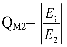
- the voltage measurement values E 1 and E 2 measured in the first measurement state M 1 and the voltage measurement values E 1 and E 2 measured in the second measurement state M 2 are evaluated together.
- Q M2 E 1 E 2 educated.
- information regarding the vertical asymmetry in each half can be obtained from the evaluation of the voltage measurements E 1 and E 2 measured in the second measuring state M 2 .
- the overall flow profile within each of the four quadrants can be determined at least qualitatively.
- the flow velocity of the fluid is additionally determined from the voltage measurement values E 1 and E 2 measured in the first measurement state M 1 .
- the measured flow profile is also taken into account when determining the flow from the flow velocity.
- the first and second coils are energized in such a way that the magnetic field of each coil is inverted, with at least the first voltage measurement value E 1 and the second voltage measurement value E 2 being determined and the first voltage measurement value E 1 and the second voltage measurement value E 2 can be taken into account when determining the vertical and/or horizontal asymmetry of the flow profile.
- This embodiment is particularly advantageous if in a first measuring state M 1 the first and second coils are energized in such a way that the first magnetic field and the second magnetic field are rectified, if in a second measuring state M 2 the first and second coils are energized in this way that the first and the second magnetic fields are directed in opposite directions to one another and when in a third measuring state M 3 the first and the second coil are energized in the opposite direction to the second measuring state M 2 in such a way that the first and the second magnetic fields are aligned in opposite directions to one another, but in the opposite direction with respect to of the second measurement state M 2 .
- the measured voltage values E 1 and E 2 are determined at the first and second electrodes.
- the flow velocity of the medium is additionally determined from the voltage measurements E 1 and E 2 measured with rectified magnetic fields.
- Type Q1 Q2 Q3 Q4 A normal normal normal normal normal normal b fast fast slow slow C fast slow fast slow D fast slow slow slow E fast slow slow fast F slow normal normal normal normal b
- the individual types A to F of the flow profile have the following voltage measurement values E 1 and E 2 in the first measurement state M 1 : Type differential
- the deflection of the charged particles within the fluid in the first measuring state M 1 corresponds to the deflection for determining the speed v of the fluid. Accordingly, the measured voltage values E 1 and E 2 can be compared with the measured value E v that is relevant for the flow measurement.
- the differential corresponds to the potential difference between the first and second electrodes.
- the information E v denotes the voltage measurement value for determining the flow rate v of the flowing fluid. If the specified measured value for E 1 or E 2 deviates by an upward or downward offset from the (half) measured value for flow determination E v , this is due to a fast or slow flow speed that deviates from the normal flow speed.
- E 1 E 2 a measure of the asymmetry between the left airfoil S 1 and the right airfoil S r .
- Reversing the direction of the excitation currents in a third measuring state M 3 causes a reversal of the sign of the measured voltages.
- one of the flow profile types A to F set out above can be assigned to the fluid.
- flow profile type D or F If one of the flow profile types A, B, C or E is not detected, then there is a flow profile in which one quadrant has a significantly higher or lower speed than the other three quadrants (flow profile type D or F).
- the task set out at the beginning is achieved by a measuring transducer for connection to a measuring sensor of a magnetic-inductive flow measuring device, comprising a control and evaluation unit, in that the control and evaluation unit is designed to carry out one of the previously described methods.
- the task set out at the beginning is achieved by a magneto-inductive flow measuring device mentioned at the beginning in that a means for generating a reference potential is present and in that the evaluation unit is designed in such a way that during operation it is based on the values measured on the electrodes Voltage measurement values, whereby the voltage measurement values are measured against the reference potential, determines the vertical and / or horizontal asymmetry of the flow profile.
- the flow measuring device carries out one of the previously described methods during operation.
- the task set out at the beginning is also achieved by the use mentioned at the beginning in that a means for generating a reference potential is present and in that the evaluation unit is designed in such a way that during operation it is based on the voltage measurements measured at the electrodes, wherein the voltage measurements are each measured against the reference potential, which determines the vertical and/or horizontal asymmetry of the flow profile.
- a magnetic-inductive flow measuring device can not only be used to determine the flow, but that it is also possible to determine horizontal and/or vertical asymmetries of the flow profile. This allows the flow profile to be taken into account when determining the flow rate, thereby improving the reliability of the measurement or the flow measuring device.
- the flow measuring device is designed as described above and/or the flow measuring device carries out one of the previously described methods during operation.
- FIG. 1 A first exemplary embodiment of a method 1 according to the invention for determining the flow profile in the measuring tube 5 of a magnetic-inductive flow measuring device 2 is shown.
- the flow measuring device 2 as in Fig. 6 shown, a transducer 3 and a transducer 4.
- the measurement sensor 4 has a measuring tube 5, a first coil 6 for generating a first magnetic field within the measuring tube 5, a second coil 7 for generating a second magnetic field within the measuring tube, a first electrode 8 and a second electrode 9 and a reference electrode 10.
- the first electrode 8 and the second electrode 9 are arranged diametrically on the measuring tube 5 for measuring a voltage occurring in the fluid.
- the reference electrode 10 is arranged at an angle of approximately 90° to the first electrode 8 and to the second electrode 9.
- the measuring transducer 4 has an evaluation unit 11.
- the first coil 6 is now energized with a first excitation current to generate a first magnetic field within the measuring tube 5.
- the second coil 7 is energized with a second excitation current 13 to generate a second magnetic field.
- the first 6 and the second coil 7 are energized in such a way that the first magnetic field and the second magnetic field are rectified.
- the individual magnetic fields overlap to form one Fig. 6 shown overall magnetic field 14.
- a first voltage E 1 is measured at the first electrode 8 against the reference potential 10 and further a second voltage E 2 is measured at the second electrode 9 against the reference potential 10 16.
- the voltage measurement values E 1 and E 2 compared with each other 17.
- the quotient is used E 1 E 2 educated. Is E 1 E 2 ⁇ 1 , taking into account a tolerance range, there is a horizontal asymmetry between the right and left halves of the airfoil.
- the flow velocity v of the fluid can be determined from the measured voltage values E 1 and E 2 .
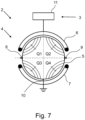
- Fig. 2 shows a second exemplary embodiment of a method 1 for determining the flow profile in the measuring tube 5 of a magnetic-inductive flow measuring device 2, the flow measuring device 2 corresponding to that in Fig. 7 flowmeter shown is designed.
- a transducer 3 and a transducer 4 the transducer 4 having a measuring tube 5, a first coil 6 for generating a first magnetic field within the measuring tube 5, a second coil 7 for generating a second magnetic field within the measuring tube, a first electrode 8 and a second electrode 9, a reference electrode 10.
- a ground ring can also be present.
- the first electrode 8 and the second electrode 9 are arranged diametrically on the measuring tube 5 for measuring a voltage occurring in the fluid and the reference electrode 10 is arranged at an angle of approximately 90 ° to the first electrode 8 and to the second electrode 9 .
- the measuring transducer has a control and evaluation unit 11.
- the first coil 6 is now energized with a first excitation current to generate a first magnetic field within the measuring tube 5.
- the second coil 7 is energized with a second excitation current 13 to generate a second magnetic field.
- the first 6 and the second coil 7 are energized in such a way that the first and the second magnetic fields are directed in opposite directions to one another.
- the in prevails within the measuring tube 5 Fig. 7 magnetic field shown.
- the measuring tube cross section can be clearly divided into four quadrants Q1 to Q4, using the in Fig. 2 Using the method shown, a vertical asymmetry between Q1 and Q3 or Q2 and Q4 can be determined.
- a first voltage E 1 is measured at the first electrode 8 against the reference potential 10 and further a second voltage E 2 is measured at the second electrode 9 against the reference potential 10 16.
- the voltages E 1 and E 2 are then evaluated to determine a vertical asymmetry of the flow profile 18. If the value of the voltage E 1 ⁇ 0, then the flow profile in the quadrants Q1 and Q3 of the left half of the measuring tube cross section is asymmetrical. If the value of the voltage E 2 ⁇ 0, the flow profile in the quadrants Q2 and Q4 of the right half of the measuring tube cross section is asymmetrical.
- Fig. 3 shows a third exemplary embodiment of a method 1 for determining the flow profile in the measuring tube 5 of a magnetic-inductive flow measuring device 2, the flow measuring device 2 having a measuring transducer 3 and a measuring sensor 4, the measuring sensor 4 having a measuring tube 5, a first coil 6 for generating a first Magnetic field within the measuring tube 5, a second coil 7 for generating a second magnetic field within the measuring tube, a first electrode 8 and a second electrode 9, a reference electrode 10.
- the first electrode 8 and the second electrode 9 are arranged diametrically on the measuring tube 5 for measuring a voltage occurring in the fluid and the reference electrode 10 is arranged at an angle of approximately 90 ° to the first electrode 8 and to the second electrode 9 .
- the measuring transducer has a control and evaluation unit 11.
- the first coil 6 is now energized with a first excitation current to generate a first magnetic field within the measuring tube 5.
- the second coil 7 is energized with a second excitation current 13 to generate a second magnetic field.
- the first 6 and the second coil 7 are energized in such a way that the first magnetic field and the second magnetic field, as in Fig. 6 shown, are aligned. This corresponds to the first measurement state M 1 of method 1.
- the voltages E 1 and E 2 are then determined 15,16.
- a next step 12 the first coil 6 is again energized and the second coil 7 is further energized 13, the coils 6, 7 now being energized in such a way that the first magnetic field and the second magnetic field, as in Fig. 7 shown are aligned in opposite directions. This corresponds to the second measurement state M 2 of method 1.
- the voltages E 1 and E 2 are then determined 15, 16. Finally, the evaluation 19 of the voltages E 1 and E 2 of the first measuring state M 1 and the second measuring state M 2 takes place for the qualitative determination of the flow profile. As part of the evaluation 19, on the one hand, by comparing the voltages E 1 and E 2 of the first measurement state M 1 , as already shown Fig. 1 described, determined whether there is a horizontal asymmetry between the left and right halves of the airfoil. In addition, how to Fig. 2 described, the voltages E 1 and E 2 of the second measuring state M 2 are evaluated to determine a vertical asymmetry.
- Fig. 4 shows a fourth exemplary embodiment of a method 1 for determining the flow profile in the measuring tube 5 of a magnetic-inductive flow measuring device 2.
- the voltages E 1 and E 2 are initially in a first measuring state M 1 , where a rectified magnetic field is present within the measuring tube 5 and then the voltages E 1 and E 2 are determined in a second measuring state M 2 , where an opposing magnetic field is present within the measuring tube 5 .
- the first coil 6 and the second coil 7 are energized again, so that a magnetic field in opposite directions is present within the measuring tube 5, each magnetic field being inverted compared to the second measuring state. This corresponds to the third measurement state M 3 .
- the voltage E 1 and the voltage E 2 are determined 15, 16.
- the flow profile is determined taking into account the voltages E 1 and E 2 of all three measuring states M 1 , M 2 and M 3 .
- Fig. 5 shows a representation of the measuring tube cross section of the measuring tube 5 through which the fluid flows, the measuring tube cross section and thus the flow profile being divided into four quadrants Q1 to Q4.
- the aforementioned flow profile types can be distinguished as follows: Type differential
- flow profile type D or F If one of the flow profile types A, B, C or E is not detected, then there is a flow profile in which one quadrant has a significantly higher or lower speed than the other three quadrants (flow profile type D or F).
- the result is a method described and illustrated with which the flow profile of a fluid flowing through a measuring tube can be determined in a spatially resolved manner. If this is taken into account when determining the flow velocity or the flow rate of the fluid, the reliability of the determination of the flow velocity or the flow rate is particularly high.
Landscapes
- Physics & Mathematics (AREA)
- Electromagnetism (AREA)
- Fluid Mechanics (AREA)
- General Physics & Mathematics (AREA)
- Engineering & Computer Science (AREA)
- Power Engineering (AREA)
- Measuring Volume Flow (AREA)
Description
Die Erfindung geht aus von einem Verfahren zur Bestimmung des Strömungsprofils im Messrohr eines magnetisch-induktiven Durchflussmessgeräts, wobei das Durchflussmessgerät wenigstens einen Messwertumformer und wenigstens einen Messwertaufnehmer aufweist, wobei der Messwertaufnehmer wenigstens ein Messrohr, wenigstens eine erste Spule zur Erzeugung eines ersten Magnetfeldes innerhalb des Messrohrs, wenigstens eine zweite Spule zur Erzeugung eines zweiten Magnetfeldes innerhalb des Messrohrs, wenigstens eine erste Elektrode und wenigstens eine zweite Elektrode aufweist, wobei die erste Elektrode und die zweite Elektrode zur Messung einer in dem Fluid auftretenden Spannung vorzugsweise diametral an dem Messrohr angeordnet sind, und wobei der Messwertumformer wenigstens eine Steuer- und Auswerteeinheit aufweist.The invention is based on a method for determining the flow profile in the measuring tube of a magnetic-inductive flow measuring device, the flow measuring device having at least one measuring transducer and at least one measuring sensor, the measuring sensor having at least one measuring tube and at least one first coil for generating a first magnetic field within the measuring tube , at least one second coil for generating a second magnetic field within the measuring tube, at least one first electrode and at least one second electrode, wherein the first electrode and the second electrode are preferably arranged diametrically on the measuring tube for measuring a voltage occurring in the fluid, and wherein the measuring transducer has at least one control and evaluation unit.
Zudem betrifft die Erfindung einen Messwertumformer zur Verbindung mit einem Messwertaufnehmer eines magnetisch-induktiven Durchflussmessgeräts, umfassend eine Steuer- und Auswerteeinheit.The invention also relates to a measuring transducer for connection to a measuring sensor of a magnetic-inductive flow measuring device, comprising a control and evaluation unit.
Darüber hinaus geht die Erfindung aus von einem magnetisch-induktiven Durchflussmessgerät mit wenigstens einem Messwertumformer und wenigstens einem Messwertaufnehmer, wobei der Messwertaufnehmer wenigstens ein Messrohr, wenigstens eine erste Spule zur Erzeugung eines ersten Magnetfeldes innerhalb des Messrohrs, wenigstens eine zweite Spule zur Erzeugung eines zweiten Magnetfeldes innerhalb des Messrohrs, wenigstens eine erste Elektrode und wenigstens eine zweite Elektrode aufweist, wobei die erste Elektrode und die zweite Elektrode zur Messung einer in dem Fluid auftretenden Spannung an dem Messrohr angeordnet sind, und wobei der Messwertumformer wenigstens eine Steuer- und Auswerteeinheit aufweist.In addition, the invention is based on a magnetic-inductive flow measuring device with at least one measuring transducer and at least one measuring sensor, the measuring sensor having at least one measuring tube, at least one first coil for generating a first magnetic field within the measuring tube, at least one second coil for generating a second magnetic field within the measuring tube, has at least one first electrode and at least one second electrode, wherein the first electrode and the second electrode are arranged on the measuring tube for measuring a voltage occurring in the fluid, and wherein the measuring transducer has at least one control and evaluation unit.
Außerdem betrifft die Erfindung die Verwendung eines magnetisch-induktiven Durchflussmessgeräts zur Bestimmung des Strömungsprofils eines durch ein Messrohr strömenden Fluids, wobei das Durchflussmessgerät wenigstens einen Messwertumformer und wenigstens einen Messwertaufnehmer aufweist, wobei der Messwertaufnehmer wenigstens ein Messrohr, wenigstens eine erste Spule zur Erzeugung eines ersten Magnetfeldes innerhalb des Messrohrs, wenigstens eine zweite Spule zur Erzeugung eines zweiten Magnetfeldes innerhalb des Messrohrs, wenigstens eine erste Elektrode und wenigstens eine zweite Elektrode aufweist, wobei die erste Elektrode und die zweite Elektrode zur Messung einer in dem Fluid auftretenden Spannung an dem Messrohr angeordnet sind, und wobei der Messwertumformer wenigstens eine Steuer- und Auswerteeinheit aufweist.The invention also relates to the use of a magnetic-inductive flowmeter for determining the flow profile of a fluid flowing through a measuring tube, the flowmeter having at least one transducer and at least one transducer, the transducer having at least one measuring tube and at least one first coil for generating a first magnetic field within the Measuring tube, at least one second coil for generating a second magnetic field within the measuring tube, at least one first electrode and at least one second electrode, the first electrode and the second electrode being arranged on the measuring tube for measuring a voltage occurring in the fluid, and wherein the measuring transducer has at least one control and evaluation unit.
Aus dem Stand der Technik ist die Bestimmung des Durchflusses eines durch ein Messrohr strömenden Mediums mittels eines magnetisch-induktiven Durchflussmessgeräts bekannt. Ein solches Durchflussmessgerät nutzt das Prinzip der elektromagnetischen Induktion zur Bestimmung der Strömungsgeschwindigkeit des Mediums. Dazu weist ein magnetisch-induktives Durchflussmessgerät in der Regel wenigstens zwei stromdurchflossene Spulen auf, die derart an dem Messrohr angeordnet sind, dass sie im Betrieb ein Magnetfeld innerhalb des Messrohrs erzeugen, das wenigstens eine Komponente aufweist, die senkrecht zur Strömungsrichtung verläuft. Aufgrund der Ablenkung der in dem Fluid vorhandenen geladenen Teilchen entsteht innerhalb des Fluids eine Spannung, die sich mittels an dem Messrohr angeordneten Elektroden nachweisen lässt. Aus der gemessenen Spannung lässt sich die Geschwindigkeit, mit der das Fluid durch das Messrohr fließt, bestimmen.The determination of the flow of a medium flowing through a measuring tube by means of a magnetic-inductive flow measuring device is known from the prior art. Such a flowmeter uses the principle of electromagnetic induction to determine the flow velocity of the medium. For this purpose, a magnetic-inductive flowmeter usually has at least two current-carrying coils, which are arranged on the measuring tube in such a way that during operation they generate a magnetic field within the measuring tube, which has at least one component that runs perpendicular to the direction of flow. Due to the deflection of the charged particles present in the fluid, a voltage arises within the fluid, which can be detected using electrodes arranged on the measuring tube. The speed at which the fluid flows through the measuring tube can be determined from the measured voltage.
Dabei wird grundlegend davon ausgegangen, dass die Geschwindigkeitsverteilung des Strömungsprofils des Fluids ungestört und damit symmetrisch ist.It is fundamentally assumed that the velocity distribution of the flow profile of the fluid is undisturbed and therefore symmetrical.
Nach einer Biegung, einer Reduzierung oder Aufweitung des Messrohrs oder nach in das Messrohr hineinragenden Elementen kann das Strömungsprofil jedoch gestört sein. Eine solche Störung kann eine vertikale und/oder eine horizontale Asymmetrie des Strömungsprofils zu Folge haben. Wird im Bereich des gestörten Strömungsprofils die Geschwindigkeit des Fluids bestimmt und bleibt die Störung des Strömungsprofils unberücksichtigt, so ist auch die Bestimmung der Geschwindigkeit bzw. des daraus abgeleiteten Volumendurchflusses fehlerhaft.However, the flow profile can be disturbed after a bend, reduction or expansion of the measuring tube or after elements protrude into the measuring tube. Such a disturbance can result in vertical and/or horizontal asymmetry of the airfoil. If the speed of the fluid is determined in the area of the disturbed flow profile and the disturbance of the flow profile is not taken into account, the determination of the speed or the volume flow derived from it is also incorrect.
Aus der Druckschrift
Das Dokument
Die europäische Patentanmeldung
Das Dokument
Grundsätzlich ist es somit aus dem Stand der Technik bekannt, Störungen des symmetrischen Strömungsprofils zu detektieren.In principle, it is therefore known from the prior art to detect disturbances in the symmetrical flow profile.
Ausgehend von diesem Stand der Technik ist es Aufgabe der vorliegenden Erfindung ein Verfahren anzugeben, mit dem das Strömungsprofil des durch ein Messrohr strömenden Fluids besonders genau bestimmt werden kann. Darüber hinaus ist es Aufgabe der Erfindung einen Messumformer und ein entsprechendes magnetisch-induktives Durchflussmessgerät anzugeben, sowie die Verwendung eines magnetisch-induktiven Durchflussmessgeräts zur Bestimmung des Strömungsprofils eines durch ein Messrohr strömenden Fluids.Based on this prior art, it is the object of the present invention to provide a method with which the flow profile of the fluid flowing through a measuring tube can be determined particularly precisely. In addition, it is the object of the invention to provide a measuring transducer and a corresponding magnetic-inductive flow measuring device, as well as the use of a magnetic-inductive flow measuring device for determining the flow profile of a fluid flowing through a measuring tube.
Gemäß einer ersten Lehre der vorliegenden Erfindung wird die zuvor genannte Aufgabe durch ein eingangs genanntes Verfahren dadurch gelöst, dass ein Mittel zum Erzeugen eines Referenzpotenzials vorhanden ist, und dass das Verfahren die folgenden Schritte umfasst:
- Bestromen der ersten Spule zur Erzeugung eines ersten Magnetfeldes mit einem ersten Erregerstrom,
- Bestromen der zweiten Spule zur Erzeugung eines zweiten Magnetfeldes mit einem zweiten Erregerstrom,
- Messung einer ersten Spannung E1 an der ersten Elektrode gegen das Referenzpotenzial,
- Messung einer zweiten Spannung E2 an der zweiten Elektrode gegen das Referenzpotenzial,
- Bestimmung der vertikalen und/oder horizontalen Asymmetrie des Strömungsprofils aus dem ersten Spannungsmesswert E1 und aus dem zweiten Spannungsmesswert E2.
- Energizing the first coil to generate a first magnetic field with a first excitation current,
- Energizing the second coil to generate a second magnetic field with a second excitation current,
- Measurement of a first voltage E 1 at the first electrode against the reference potential,
- Measuring a second voltage E 2 at the second electrode against the reference potential,
- Determination of the vertical and/or horizontal asymmetry of the flow profile from the first measured voltage value E 1 and from the second measured voltage value E 2 .
Erfindungsgemäß wurde erkannt, dass das Strömungsprofil des Fluids in einem Messrohr eines magnetisch-induktiven Durchflussmessgeräts besonders genau bestimmt werden kann, wenn die in einzelnen Teilbereichen des Messrohrs bzw. des Strömungsquerschnitts abfallende Spannung gesondert gegen ein Referenzpotenzial gemessen wird. Die in einzelnen Teilbereichen abfallende Spannung ist insbesondere abhängig von dem Magnetfeld innerhalb des Messrohrs sowie von der Geschwindigkeitsverteilung des Fluids an der Messstelle. Durch Variation des Magnetfeldes innerhalb des Messrohrs bzw. der durch die einzelnen Spulen erzeugten Magnetfelder lassen sich, wie weiter unten näher erläutert wird, verschiedene Messzustände erzeugen. Durch die gesonderte Messung der Spannungen E1 und E2 an jeder Elektrode in den verschiedenen Messzuständen lässt sich das Strömungsprofil in den einzelnen Teilbereichen durch die Auswirkung unterschiedlicher Magnetfelder charakterisieren.According to the invention, it was recognized that the flow profile of the fluid in a measuring tube of a magnetic-inductive flow measuring device can be determined particularly precisely if the voltage falling in individual subregions of the measuring tube or the flow cross section is measured separately against a reference potential. The voltage that drops in individual areas depends in particular on the magnetic field within the measuring tube and on the velocity distribution of the fluid at the measuring point. By varying the magnetic field within the measuring tube or the magnetic fields generated by the individual coils, different measuring states can be created, as will be explained in more detail below. By measuring the voltages E 1 and E 2 separately at each electrode in the different measuring states, the flow profile in the individual sub-areas can be characterized by the effect of different magnetic fields.
Gemäß einer Ausgestaltung weisen der erste und der zweite Erregerstrom die gleiche Stromstärke auf, sodass das erste Magnetfeld und das zweite Magnetfeld innerhalb des Messrohre symmetrisch ausgebildet sind. Die erste und die zweite Spule sind in insbesondere in Reihe geschaltet. Alternativ kann die Bestromung auch unabhängig voneinander durch getrennte Stromkreise erfolgen. Denkbar ist ebenfalls, dass die Erregerströme unterschiedliche Stromstärken aufweisen.According to one embodiment, the first and second excitation currents have the same current strength, so that the first magnetic field and the second magnetic field are formed symmetrically within the measuring tube. The first and second coils are in particular connected in series. Alternatively, the power can also be supplied independently through separate circuits take place. It is also conceivable that the excitation currents have different current strengths.
Das Referenzpotenzial weist vorzugsweise ein Massepotential auf und ist als Referenzelektrode oder als Erdungsring ausgestaltet. Die erste und die zweite Elektrode sind erfindungsgemäß diametral derart angeordnet, dass die Verbindungslinie der Elektroden senkrecht in Bezug auf ein von den Spulen erzeugtes gleichsinniges Magnetfeld zur Bestimmung der Strömungsgeschwindigkeit des Fluids angeordnet ist. Das Mittel zur Erzeugung des Referenzpotenzials ist vorzugsweise in einem Winkel von ca. 90° zu den Elektroden angeordnet. Diese Ausgestaltung weist den Vorteil auf, dass je nach Ausbildung des Magnetfeldes sowohl eine vertikale als auch eine horizontale Asymmetrie des Strömungsprofils bestimmbar ist.The reference potential preferably has a ground potential and is designed as a reference electrode or as a ground ring. According to the invention, the first and second electrodes are arranged diametrically in such a way that the connecting line of the electrodes is arranged perpendicularly with respect to a magnetic field in the same direction generated by the coils for determining the flow velocity of the fluid. The means for generating the reference potential is preferably arranged at an angle of approximately 90° to the electrodes. This configuration has the advantage that, depending on the formation of the magnetic field, both a vertical and a horizontal asymmetry of the flow profile can be determined.
Gemäß einer weiteren vorteilhaften Ausgestaltung werden die erste und die zweite Spule derart bestromt, dass das erste Magnetfeld und das zweite Magnetfeld gleichgerichtet sind, wobei die Bestimmung der horizontalen Asymmetrie des Strömungsprofils aus dem Vergleich des ersten Spannungsmesswertes E1 und des zweiten Spannungsmesswertes E2 erfolgt. Insbesondere wenn die Elektroden und das Mittel zur Erzeugung eines Referenzpotenzials wie zuvor beschrieben angeordnet sind, kann mit dieser Ausgestaltung des Verfahrens eine horizontale Asymmetrie des Strömungsprofils besonders leicht bestimmt werden. Dabei ist der Spannungsmesswert E1 ein Maß für die Ablenkung der geladenen Teilchen beispielsweise in der linken Hälfte des Messrohr, während der Spannungsmesswert E2 ein Maß für die Ablenkung der geladenen Teilchen beispielsweise in der rechten Hälfte des Messrohrs ist. Dabei unterscheiden sich E1 und E2 im Vorzeichen. Der Betrag der Spannungsmesswerte E1 und E2 ist insofern jeweils ein Maß für die Geschwindigkeit des Fluids beispielsweise in der rechten und der linken Hälfte des Messrohrs. Besonders bevorzugt wird aus den gemessenen Spannungsmesswerten E1 und E2 die Strömungsgeschwindigkeit des Fluids bestimmt. Zur Beurteilung, ob eine horizontale Asymmetrie des Strömungsprofils vorliegt, werden die Spannungen E1 und E2, insbesondere die Beträge der Spannungen E1 und E2 beispielsweise durch Bildung eines Quotienten oder durch Summen- oder Differenzbildung miteinander verglichen. Weicht der Vergleich der Spannungen von einem zuvor festgelegten Grenzwert ab, so ist dies auf eine horizontale Asymmetrie des Strömungsgprofils zurückzuführen. Vorzugsweise weist das Strömungsprofil dann eine asymmetrische Störung auf wenn die Abweichung von dem Grenzwert außerhalb eines Toleranzbereiches um den Grenzwert liegt. Der Toleranzbereich beträgt in einer bevorzugten Ausgestaltung 10% des Grenzwertes, in einer besonders bevorzugten Ausgestaltung 5% des Grenzwertes und in einer weiteren besonders bevorzugten Ausgestaltung 2% des Grenzwertes. Dabei ist die Asymmetrie umso größer, je höher die Abweichung von dem Grenzwert ist.According to a further advantageous embodiment, the first and second coils are energized in such a way that the first magnetic field and the second magnetic field are rectified, with the horizontal asymmetry of the flow profile being determined from the comparison of the first voltage measurement value E 1 and the second voltage measurement value E 2 . In particular, if the electrodes and the means for generating a reference potential are arranged as described above, a horizontal asymmetry of the flow profile can be determined particularly easily with this embodiment of the method. The voltage measurement value E 1 is a measure of the deflection of the charged particles, for example in the left half of the measuring tube, while the voltage measurement value E 2 is a measure of the deflection of the charged particles, for example in the right half of the measuring tube. E 1 and E 2 differ in sign. The magnitude of the voltage measurements E 1 and E 2 is therefore a measure of the speed of the fluid, for example in the right and left halves of the measuring tube. The flow velocity of the fluid is particularly preferably determined from the measured voltage values E 1 and E 2 . To assess whether there is a horizontal asymmetry of the flow profile, the voltages E 1 and E 2 , in particular the amounts of the voltages E 1 and E 2 , are compared with one another, for example by forming a quotient or by forming a sum or difference. If the comparison of the voltages deviates from a previously established limit, then this is due to a horizontal asymmetry of the flow profile. The flow profile preferably has an asymmetrical disturbance if the deviation from the limit value lies outside a tolerance range around the limit value. In a preferred embodiment, the tolerance range is 10% of the limit value, in a particularly preferred embodiment it is 5% of the limit value and in a further particularly preferred embodiment it is 2% of the limit value. The higher the deviation from the limit value, the greater the asymmetry.
Gemäß einer weiteren vorteilhafte Ausgestaltung werden die erste und die zweite Spule alternativ oder zeitlich vor oder nach der Erzeugung von gleichgerichteten Magnetfeldern derart bestromt, dass das erste und das zweite Magnetfeld einander entgegengerichtet sind, wobei die Bestimmung der Asymmetrie des Strömungsprofils aus dem ersten Spannungsmesswert E1 und dem zweiten Spannungsmesswert E2 erfolgt. Insbesondere wenn die Elektroden und das Mittel zur Erzeugung eines Referenzpotenzials wie zuvor beschrieben angeordnet sind, kann mit dieser Ausgestaltung des Verfahrens eine vertikale Asymmetrie in jeder Hälfte des Strömungsprofils besonders leicht bestimmt werden.According to a further advantageous embodiment, the first and second coils are energized alternatively or temporally before or after the generation of rectified magnetic fields in such a way that the first and second magnetic fields are opposite to one another, with the determination of the asymmetry of the flow profile from the first voltage measurement value E 1 and the second voltage measurement value E 2 takes place. In particular, if the electrodes and the means for generating a reference potential are arranged as described above, a vertical asymmetry in each half of the flow profile can be determined particularly easily with this embodiment of the method.
Ist die erste Elektrode an der linken Hälfte des Messrohrs angeordnet und die zweite Elektrode an der rechten Hälfte des Messrohrs angeordnet, werden wie bereits zuvor beschrieben, zunächst die in der linken Hälfte anfallende Spannung E1 und die in der rechten Hälfte des Messrohrs anfallende Spannung E2 bestimmt.If the first electrode is arranged on the left half of the measuring tube and the second electrode is arranged on the right half of the measuring tube, as already described above, the voltage E 1 occurring in the left half and the voltage E occurring in the right half of the measuring tube are initially determined 2 determined.
Ist das vertikale Strömungsprofil in der rechten bzw. in der linken Hälfte des Messrohrs symmetrisch, so beträgt die Spannung E1 bzw. E2 0V. Ist das Strömungsprofil beispielsweise in der linken Hälfte des Messrohrs vertikal nicht symmetrisch, so ist E1 ≠ 0 V. Ist das Strömungsprofil in der rechten Hälfte des Messrohrs vertikal nicht symmetrisch, so ist E2 ≠ 0 V. Ist der Betrag von E1 und E2 gleich groß, so ist die vertikale Asymmetrie auf beiden Seiten des Messrohrs im Mittel identisch. Ist jedoch der Betrag der gemessenen Spannungen unterschiedlich, d.h. |E 1|≠|E 2|, weist das Strömungsprofil auf beiden Seiten eine vertikale Asymmetrie und zusätzlich eine horizontale Asymmetrie auf.If the vertical flow profile in the right or left half of the measuring tube is symmetrical, the voltage E 1 or E 2 is 0V. For example, if the flow profile in the left half of the measuring tube is not vertically symmetrical, then E 1 ≠ 0 V. If the flow profile in the right half of the measuring tube is not vertically symmetrical, then E 2 ≠ 0 V. Is the magnitude of E 1 and E 2 is the same size, then the vertical asymmetry on both sides of the measuring tube is on average identical. However, if the magnitude of the measured voltages is different, i.e. | E 1 |≠| E 2 |, the flow profile has a vertical asymmetry on both sides and an additional horizontal asymmetry.
Gemäß einer besonders bevorzugten Ausgestaltung werden in einem ersten Messzustand M1 die erste und die zweite Spule derart bestromt, dass das erste und das zweite Magnetfeld gleichgerichtet sind, wobei zumindest der erste Spannungsmesswert E1 und der zweite Spannungsmesswert E2 bestimmt werden und in einem zweiten Messzustand M2 werden die erste und die zweite Spule derart bestromt, dass das erste und das zweite Magnetfeld einander entgegengerichtet sind, wobei zumindest der erste Spannungsmesswert E1 und der zweite Spannungsmesswert E2 bestimmt werden und die Bestimmung der vertikalen und der horizontalen Asymmetrie erfolgt aus den im ersten Messzustand bestimmten Spannungsmesswerten E1 und E2 und aus den im zweiten Messzustand bestimmten Spannungsmesswerten E1 und E2. Besonders bevorzugt sind dieser Ausgestaltung die erste und die zweite Elektrode und das Mittel zur Erzeugung eines Referenzpotenzials wie zuvor beschrieben angeordnet.According to a particularly preferred embodiment, in a first measuring state M 1 the first and second coils are energized in such a way that the first and second magnetic fields are rectified, with at least the first voltage measurement value E 1 and the second voltage measurement value E 2 being determined and in a second In the measuring state M 2 , the first and second coils are energized in such a way that the first and second magnetic fields are directed in opposite directions, at least the first voltage measurement value E 1 and the second voltage measurement value E 2 being determined and the vertical and horizontal asymmetry being determined the voltage measurement values E 1 and E 2 determined in the first measurement state and from the voltage measurement values E 1 and E 2 determined in the second measurement state. In this embodiment, the first and second electrodes and the means for generating a reference potential are particularly preferably arranged as described above.
Anschaulich lässt sich das Strömungsprofil in vier Quadranten einteilen, wobei mittels der zuvor beschrieben Ausgestaltung sowohl eine vertikale Asymmetrie innerhalb der rechten und der linken Hälfte bestimmt werden kann als auch eine horizontale Asymmetrie zwischen der rechten und der linken Hälfte. Dazu werden insbesondere die in dem ersten Messzustand M1 gemessenen Spannungsmesswerte E1 und E2 und die in dem zweiten Messzustand M2 gemessenen Spannungsmesswerte E1 und E2 gemeinsam ausgewertet. Es wird insbesondere der Betrag des Quotienten der in dem ersten Messzustand M1 gemessenen Spannungsmesswerten 
Ist QM1 = 1, so weist das Strömungsprofil im Mittel keine horizontale Asymmetrie insbesondere zwischen der rechten und der linken Messrohrhälfte auf. Ist QM1 ≠ 1, so weist das Strömungsprofil eine horizontale Asymmetrie auf.If Q M1 = 1, then on average the flow profile has no horizontal asymmetry, particularly between the right and left half of the measuring tube. If Q M1 ≠ 1, the flow profile has a horizontal asymmetry.
Ist QM2 = 1, so weist das Strömungsprofil eine vertikale Asymmetrie insbesondere zwischen der oberen und der unteren Messrohrhälfte auf. Ist QM2 ≠ 1, so weist das Strömungsprofil eine vertikale und eine horizontale Asymmetrie auf.If Q M2 = 1, the flow profile has a vertical asymmetry, particularly between the upper and lower half of the measuring tube. If Q M2 ≠ 1, the flow profile has a vertical and a horizontal asymmetry.
Zudem kann aus der Auswertung der im zweiten Messzustand M2 gemessenen Spannungsmesswerte E1 und E2 eine Information bezüglich der vertikalen Asymmetrie in jeder Hälfte gewonnen werden.In addition, information regarding the vertical asymmetry in each half can be obtained from the evaluation of the voltage measurements E 1 and E 2 measured in the second measuring state M 2 .
So lässt sich insgesamt das Strömungsprofil innerhalb jedes der vier Quadranten zumindest qualitativ bestimmen.In this way, the overall flow profile within each of the four quadrants can be determined at least qualitatively.
Besonders bevorzugt wird zudem aus den im ersten Messzustand M1 gemessenen Spannungsmesswerten E1 und E2 zusätzlich die Strömungsgeschwindigkeit des Fluids bestimmt. Besonders bevorzugt wird bei der Bestimmung des Durchflusses aus der Strömungsgeschwindigkeit ebenfalls das gemessene Strömungsprofil berücksichtigt.Particularly preferably, the flow velocity of the fluid is additionally determined from the voltage measurement values E 1 and E 2 measured in the first measurement state M 1 . Particularly preferably, the measured flow profile is also taken into account when determining the flow from the flow velocity.
Gemäß einer weiteren vorteilhaften Ausgestaltung werden in einem zusätzlichen Messzustand die erste und die zweite Spule derart bestromt, dass das Magnetfeld jeder Spule invertiert wird, wobei zumindest der erste Spannungsmesswert E1 und der zweite Spannungsmesswert E2 bestimmt werden und wobei der erste Spannungsmesswert E1 und der zweite Spannungsmesswert E2 bei der Bestimmung der vertikalen und/oder horizontalen Asymmetrie des Strömungsprofils berücksichtigt werden.According to a further advantageous embodiment, in an additional measuring state, the first and second coils are energized in such a way that the magnetic field of each coil is inverted, with at least the first voltage measurement value E 1 and the second voltage measurement value E 2 being determined and the first voltage measurement value E 1 and the second voltage measurement value E 2 can be taken into account when determining the vertical and/or horizontal asymmetry of the flow profile.
Diese Ausgestaltung ist insbesondere vorteilhaft, wenn in einem ersten Messzustand M1 die erste und die zweite Spule derart bestromt werden, dass das erste Magnetfeld und das zweite Magnetfeld gleichgerichtet sind, wenn in einem zweiten Messzustand M2 die erste und die zweite Spule derart bestromt werden, dass das erste und das zweite Magnetfeld einander entgegengerichtet sind und wenn in einem dritten Messzustand M3 die erste und die zweite Spule umgekehrt zum zweiten Messzustand M2 derart bestromt werden, dass das erste und das zweite Magnetfeld gegensinnig zueinander ausgerichtet sind, jedoch umgekehrt bezüglich des zweiten Messzustandes M2. Zudem werden in jedem Messzustand M1, M2 und M3 die Spannungsmesswerte E1 und E2 an der ersten und der zweiten Elektrode bestimmt.This embodiment is particularly advantageous if in a first measuring state M 1 the first and second coils are energized in such a way that the first magnetic field and the second magnetic field are rectified, if in a second measuring state M 2 the first and second coils are energized in this way that the first and the second magnetic fields are directed in opposite directions to one another and when in a third measuring state M 3 the first and the second coil are energized in the opposite direction to the second measuring state M 2 in such a way that the first and the second magnetic fields are aligned in opposite directions to one another, but in the opposite direction with respect to of the second measurement state M 2 . In addition, in each measurement state M 1 , M 2 and M 3 , the measured voltage values E 1 and E 2 are determined at the first and second electrodes.
Durch die zusätzliche Berücksichtigung des umgekehrten gegensinnigen Magnetfeldes lässt sich eine weitere Differenzierung der möglichen Strömungsprofile vornehmen.By additionally taking into account the reverse magnetic field in the opposite direction, a further differentiation of the possible flow profiles can be made.
Gemäß einer weiteren vorteilhaften Ausgestaltung wird aus den bei gleichgerichteten Magnetfeldern gemessenen Spannungsmesswerten E1 und E2 zusätzlich die Strömungsgeschwindigkeit des Mediums bestimmt.According to a further advantageous embodiment, the flow velocity of the medium is additionally determined from the voltage measurements E 1 and E 2 measured with rectified magnetic fields.
Es ist vorteilhaft, wenn in der Auswerteeinheit eine Mehrzahl von Strömungsprofilen in Form von verschiedenen Spannungsverhältnissen zwischen der ersten und der zweiten Elektrode, insbesondere unter Berücksichtigung verschiedener Messzustände, hinterlegt ist und wenn die Bestimmung der vertikalen und/oder horizontalen Asymmetrie des Strömungsprofils mittels einer Abfrage bezüglich dieser Spannungsverhältnisse erfolgt.It is advantageous if a plurality of flow profiles in the form of different voltage ratios between the first and second electrodes are stored in the evaluation unit, in particular taking into account different measurement states, and if the vertical and/or horizontal asymmetry of the flow profile is determined by means of a query regarding these tensions occur.
Beispielsweise können qualitativ die folgenden tabellarisch aufgeführten Arten von Strömungsprofilen unterschieden, wobei Q1 bis Q4 jeweils einen Quadranten des Strömungsprofils bezeichnet, und wobei im Einzelnen Q1 links oben, Q2 rechts oben, Q3 links unten und Q4 rechts unten angeordnet sind:
Die einzelnen Typen A bis F des Strömungsprofils weisen im ersten Messzustand M1 folgende Spannungsmesswerte E1 und E2 auf:
![]()
![]()
In der obige Tabelle entspricht das Differenzial der Potenzialdifferenz zwischen der ersten und der zweiten Elektrode. Die Angabe Ev bezeichnet den Spannungsmesswert zur Bestimmung der Durchflussgeschwindigkeit v des strömenden Fluids. Weicht der angegebene Messwert für E1 bzw. E2 um einen Offset nach oben oder nach unten von dem (halben) Messwert für die Durchflussbestimmung Ev ab, so ist dies zurückzuführen auf eine von der normalen Durchflussgeschwindigkeit abweichende schnelle oder langsame Fließgeschwindigkeit. Insbesondere die in der fünften Spalte angegebenen Werte für den Quotienten E1/E2 weisen auf eine horizontale Asymmetrie zwischen der linken und der rechten Messrohrhälfte hin. In den Fällen in denen im Mittel keine horizontale Asymmetrie vorliegt, also bei den Strömungsprofiltypen A, B und E, ist 
![]()
![]()
Im zweiten Messzustand M2 ergeben sich für die genannten Strömungsprofiltypen folgende Werte:
![]()
![]()
Da die Ablenkung der geladenen Teilchen im Fluid in dem zweiten Messzustand M2 aufgrund der gegensinnig wirkenden Magnetfelder von der Richtung der Ablenkung der Teilchen zur Messung der Durchflussgeschwindigkeit abweicht, kann den in dem zweiten Messzustand M2 bestimmten Spannungsmesswerten E1 und E2 keine Information bezüglich der Durchflussgeschwindigkeit v entnommen werden. Vielmehr wird in dem zweiten Messzustand M2 nur dann eine Spannung E1 und/oder E2 in der linken bzw. der rechten Messrohrhälfte gemessen, wenn in der linken bzw. in der rechten Messrohrhälfte ein vertikal asymmetrisches Strömungsprofil vorliegt. Ist das vertikale Strömungsprofil im Hinblick auf die Strömungsgeschwindigkeit in einer Messrohrhälfte symmetrisch, ist an der Elektrode keine Spannung messbar. In der zuvor gezeigten Tabelle ist das Verhältnis ![]()
![]()
Eine Umkehr der Richtung der Erregerströme in einem dritten Messzustand M3 bewirkt eine Vorzeichenumkehr der gemessenen Spannungen.Reversing the direction of the excitation currents in a third measuring state M 3 causes a reversal of the sign of the measured voltages.
Durch Messung der Spannungen E1 und E2 in dem ersten Messzustand M1 und in dem zweiten Messzustand M2 und vorzugsweise auch dem dritten Messzustand M3 kann dem Fluid damit einer der oben dargelegten Strömungsprofiltypen A bis F zugeordnet werden.By measuring the voltages E 1 and E 2 in the first measuring state M 1 and in the second measuring state M 2 and preferably also the third measuring state M 3 , one of the flow profile types A to F set out above can be assigned to the fluid.
Vorzugsweise ist dazu in der Auswerteeinheit der folgende Algorithmus hinterlegt:
- Measure M1
- quotient_1 = E1/E2
- Measure M2
- E1 _2 = E1
- E2_2 = E2
- quotient_2 = E1/E2
- sum_2 = E1 + E2
- delta_2 = E1 - E2
- Measure M2 with reversed magnetic field
- sum_2_rev = E1 + E2
- If (quotient_2 = 1) AND (quotient_1 = 1) then
- If (sum_2 = sum_2_rev) then FLOWPROFILE A
- If (sum_2 ≠ sum_2_rev) then FLOWPROFILE_E
- If not(FLOWPROFILE A) or not(FLOWPROFILE E) and (quotient_1=1) then FLOWPROFILE_B
- If not(FLOWPROFILE A or FLOWPROFILE E or FLOWPROFILE B) and (quotient_2=1) then FLOWPROFILE_C
Sofern nicht einer der Strömungsprofiltypen A, B, C oder E detektiert wird, so liegt ein Strömungsprofil vor, in dem ein Quadrant eine signifikant höhere oder niedrigere Geschwindigkeit als die übrigen drei Quadranten aufweist (Strömungsprofiltyp D oder F).If one of the flow profile types A, B, C or E is not detected, then there is a flow profile in which one quadrant has a significantly higher or lower speed than the other three quadrants (flow profile type D or F).
Folgender Algorithmus kann beispielsweise zur weiteren Identifizierung des Strömungsprofiltyps eingesetzt werden:
- If (E2_2 = 0) and (E1_2 > 0) and (quotient_1 = "left part") then FLOWPROFILE D_Q1_fast
- If (E2_2 = 0) and (E1_2 < 0) and (quotient_1 = "left part") then FLOWPROFILE_D_Q3_fast
- If (E1_2 = 0) and (E2_2 > 0) and (quotient_1 = "right part") then FLOWPROFILE_D_Q2_fast
- If (E1_2 = 0) and (E2_2 < 0) and (quotient_1 = "right part") then FLOWPROFILE_D_Q4_fast
- If (E2_2 = 0) and (E1_2 < 0) and (quotient_1 = "right part") then FLOWPROFILE_F_Q1_slow
- If (E2_2 = 0) and (E1_2 > 0) and (quotient_1 = "right part") then FLOWPROFILE_D_Q3_slow
- If (E1_2 = 0) and (E2_2 < 0) and (quotient_1 = "left part") then FLOWPROFILE_D_Q2_slow
- If (E1_2 = 0) and (E2_2 > 0) and (quotient_1 = "left part") then FLOWPROFILE_D_Q4_slow
Neben den zuvor beispielhaft beschriebenen konkreten Strömungsprofiltypen und dem Algorithmus zur Einordnung der Profiltypen anhand der gemessenen Spannungen lassen sich natürlich weitere Strömungsprofiltypen mit anderen Geschwindigkeitsverteilungen voneinander unterscheiden und insbesondere durch eine Messung der Spannungen E1 und E2 in verschiedenen Messzuständen klassifizieren.In addition to the specific flow profile types described above as examples and the algorithm for classifying the profile types based on the measured voltages, other flow profile types with different speed distributions can of course be distinguished from one another and classified in particular by measuring the voltages E 1 and E 2 in different measurement states.
Gemäß einer zweiten Lehre wird die eingangs dargelegte Aufgabe durch einen Messwertumformer zur Verbindung mit einem Messwertaufnehmer eines magnetisch-induktiven Durchflussmessgeräts, umfassend eine Steuer- und Auswerteeinheit, dadurch gelöst, dass die Steuer- und Auswerteeinheit zur Durchführung eines der zuvor beschriebenen Verfahrens ausgestaltet ist.According to a second teaching, the task set out at the beginning is achieved by a measuring transducer for connection to a measuring sensor of a magnetic-inductive flow measuring device, comprising a control and evaluation unit, in that the control and evaluation unit is designed to carry out one of the previously described methods.
Gemäß einer dritten Lehre der vorliegenden Erfindung wird die eingangs dargelegte Aufgabe durch ein eingangs genanntes magnetisch-induktives Durchflussmessgerät dadurch gelöst, dass ein Mittel zum Erzeugen eines Referenzpotenzials vorhanden ist und dass die Auswerteeinheit derart ausgestaltet ist, dass sie im Betrieb aus den an den Elektroden gemessenen Spannungsmesswerten, wobei die Spannungsmesswerte jeweils gegen das Referenzpotenzial gemessen werden, die vertikale und/oder horizontale Asymmetrie des Strömungsprofils bestimmt.According to a third teaching of the present invention, the task set out at the beginning is achieved by a magneto-inductive flow measuring device mentioned at the beginning in that a means for generating a reference potential is present and in that the evaluation unit is designed in such a way that during operation it is based on the values measured on the electrodes Voltage measurement values, whereby the voltage measurement values are measured against the reference potential, determines the vertical and / or horizontal asymmetry of the flow profile.
Gemäß einer besonders bevorzugten Ausgestaltung führt das Durchflussmessgerät im Betrieb eines der zuvor beschriebenen Verfahren durch.According to a particularly preferred embodiment, the flow measuring device carries out one of the previously described methods during operation.
Gemäß einer vierten Lehre der vorliegenden Erfindung wird die eingangs dargelegte Aufgabe durch die eingangs genannte Verwendung ebenfalls dadurch gelöst, dass ein Mittel zum Erzeugen eines Referenzpotenzials vorhanden ist und dass die Auswerteeinheit derart ausgestaltet ist, dass sie im Betrieb aus den an den Elektroden gemessenen Spannungsmesswerten, wobei die Spannungsmesswerte jeweils gegen das Referenzpotenzial gemessen werden, die vertikale und/oder horizontale Asymmetrie des Strömungsprofils bestimmt.According to a fourth teaching of the present invention, the task set out at the beginning is also achieved by the use mentioned at the beginning in that a means for generating a reference potential is present and in that the evaluation unit is designed in such a way that during operation it is based on the voltage measurements measured at the electrodes, wherein the voltage measurements are each measured against the reference potential, which determines the vertical and/or horizontal asymmetry of the flow profile.
Erfindungsgemäß wurde damit erkannt, dass ein magnetisch-induktives Durchflussmessgerät nicht nur für die Bestimmung des Durchflusses eingesetzt werden kann, sondern dass es ebenfalls möglich ist, horizontale und/oder vertikale Asymmetrien des Strömungsprofils zu bestimmen. Dadurch kann das Strömungsprofil bei der Bestimmung des Durchflussgeschwindigkeit berücksichtigt werden, wodurch die Zuverlässigkeit der Messung bzw. des Durchflussmessgeräts verbessert wird.According to the invention, it was thus recognized that a magnetic-inductive flow measuring device can not only be used to determine the flow, but that it is also possible to determine horizontal and/or vertical asymmetries of the flow profile. This allows the flow profile to be taken into account when determining the flow rate, thereby improving the reliability of the measurement or the flow measuring device.
Gemäß einer bevorzugten Ausgestaltung ist das Durchflussmessgerät wie zuvor beschrieben ausgestaltet und/oder das Durchflussmessgerät führt im Betrieb eines der zuvor beschriebenen Verfahren durch.According to a preferred embodiment, the flow measuring device is designed as described above and/or the flow measuring device carries out one of the previously described methods during operation.
Im Einzelnen gibt es nun eine Vielzahl von Möglichkeiten das erfindungsgemäße Verfahren, das erfindungsgemäße Durchflussmessgerät und die erfindungsgemäße Verwendung auszugestalten und weiterzubilden. Dazu wird verwiesen sowohl auf die den unabhängigen Patentansprüchen nachgeordneten Patentansprüche als auch auf die nachfolgende Beschreibung von bevorzugten Ausführungsbeispielen in Verbindung mit der Zeichnung.In detail, there are now a variety of possibilities for designing and developing the method according to the invention, the flow measuring device according to the invention and the use according to the invention. Reference is made to both the patent claims subordinate to the independent patent claims and to the following description of preferred exemplary embodiments in conjunction with the drawing.
In der Zeichnung zeigen
- Fig. 1
- ein erstes Ausführungsbeispiel eines erfindungsgemäße Verfahrens,
- Fig. 2
- ein zweites Ausführungsbeispiel eines erfindungsgemäßen Verfahrens,
- Fig. 3
- ein drittes Ausführungsbeispiel eines erfindungsgemäßen Verfahrens,
- Fig. 4
- ein viertes Ausführungsbeispiel eines erfindungsgemäßen Verfahrens,
- Fig. 5
- eine schematische Darstellung verschiedener Strömungsprofile des Fluids,
- Fig. 6
- ein erstes Ausführungsbeispiel einer erfindungsgemäßen Vorrichtung und
- Fig. 7
- ein zweites Ausführungsbeispiel einer erfindungsgemäßen Vorrichtung.
- Fig. 1
- a first exemplary embodiment of a method according to the invention,
- Fig. 2
- a second embodiment of a method according to the invention,
- Fig. 3
- a third embodiment of a method according to the invention,
- Fig. 4
- a fourth exemplary embodiment of a method according to the invention,
- Fig. 5
- a schematic representation of various flow profiles of the fluid,
- Fig. 6
- a first embodiment of a device according to the invention and
- Fig. 7
- a second embodiment of a device according to the invention.
In
In einem ersten Schritt 12 des in
Im dargestellten Ausführungsbeispiel werden die erste 6 und die zweite Spule 7 derart bestromt, dass das erste Magnetfeld und das zweite Magnetfeld gleichgerichtet sind. Die einzelnen Magnetfelder überlagern sich zu einem in
In einem nächsten Schritt 15 des Verfahrens wird eine erste Spannung E1 an der ersten Elektrode 8 gegen das Referenzpotenzial 10 gemessen und weiterhin wird eine zweite Spannung E2 an der zweiten Elektrode 9 gegen das Referenzpotenzial 10 gemessen 16. Anschließend werden die Spannungsmesswerte E1 und E2 miteinander verglichen 17. Dazu wird vorliegend der Quotient ![]()

![]()
Zusätzlich kann aus den gemessenen Spannungswerten E1 und E2 die Strömungsgeschwindigkeit v des Fluids bestimmt werden.In addition, the flow velocity v of the fluid can be determined from the measured voltage values E 1 and E 2 .
In einem ersten Schritt 12 des in
In einem nächsten Schritt 15 des Verfahrens wird eine erste Spannung E1 an der ersten Elektrode 8 gegen das Referenzpotenzial 10 gemessen und weiterhin wird eine zweite Spannung E2 an der zweiten Elektrode 9 gegen das Referenzpotenzial 10 gemessen 16.In a
Anschließend werden zur Bestimmung einer vertikalen Asymmetrie des Strömungsprofils die Spannungen E1 und E2 ausgewertet 18. Ist der Wert der Spannung E1 ≠ 0, so ist das Strömungsprofil in den Quadranten Q1 und Q3 der linken Hälfte des Messrohrquerschnitts asymmetrisch. Ist der Wert der Spannung E2 ≠ 0, so ist das Strömungsprofil in den Quadranten Q2 und Q4 der rechten Hälfte des Messrohrquerschnitts asymmetrisch.The voltages E 1 and E 2 are then evaluated to determine a vertical asymmetry of the
In einem ersten Schritt 12 des in
In einem nächsten Schritt 12 wird erneut die erste Spule 6 bestromt und weiterhin wird die zweite Spule 7 bestromt 13, wobei die Spulen 6, 7 nun derart bestromt werden, dass das erste Magnetfeld und das zweite Magnetfeld, wie in
Anschließend werden die Spannungen E1 und E2 bestimmt 15, 16. Schließlich erfolgt die Auswertung 19 der Spannungen E1 und E2 des ersten Messzustandes M1 und des zweiten Messzustandes M2 zur qualitativen Bestimmung des Strömungsprofils. Im Rahmen der Auswertung 19 wird zum einen durch den Vergleich der Spannungen E1 und E2 des ersten Messzustandes M1, wie bereits zu
Im ersten Messzustand M1 lassen sich die zuvor genannten Strömungsprofiltypen wie folgt unterscheiden:

Im zweiten Messzustand ergeben sich für die genannten Strömungsprofiltypen folgende Werte:
![]()
![]()
Die Bestimmung des Strömungsprofils erfolgt im dargestellten Ausführungsbeispiel durch den folgenden Algorithmus:
- Measure M1
- quotient_1 = E1/E2
- Measure M2
- E1_2=E1
- E2_2 = E2
- quotient_2 = E1/E2
- sum_2 = E1 + E2
- delta_2 = E1 - E2
- Measure M2 with reversed magnetic field
- sum_2_rev = E1 + E2
- If (quotient_2 = 1) AND (quotient_1 = 1) then
- If (sum_2 = sum_2_rev) then FLOWPROFILE A
- If (sum_2 ≠ sum_2_rev) then FLOWPROFILE E
- If not(FLOWPROFILE A) or not(FLOWPROFILE E) and (quotient_1=1) then FLOWPROFILE_B
- If not(FLOWPROFILE A or FLOWPROFILE E or FLOWPROFILE_B) and (quotient_2=1) then FLOWPROFILE_C
Sofern nicht eines der Strömungsprofiltypen A, B, C oder E detektiert wird, so liegt ein Strömungsprofil vor, in dem ein Quadrant eine signifikant höhere oder niedrigere Geschwindigkeit als die übrigen drei Quadranten aufweist (Strömungsprofiltyp D oder F).If one of the flow profile types A, B, C or E is not detected, then there is a flow profile in which one quadrant has a significantly higher or lower speed than the other three quadrants (flow profile type D or F).
Folgender Algorithmus kann beispielsweise zur weiteren Identifizierung des Strömungsprofiltyps eingesetzt werden:
- If (E2_2 = 0) and (E1_2 > 0) and (quotient_1 = "left part") then FLOWPROFILE D_Q 1_fast
- If (E2_2 = 0) and (E1_2 < 0) and (quotient_1 = "left part") then FLOWPROFILE_D_Q3_fast
- If (E1_2 = 0) and (E2_2 > 0) and (quotient_1 = "right part") then FLOWPROFILE_D_Q2_fast
- If (E1_2 = 0) and (E2_2 < 0) and (quotient_1 = "right part") then FLOWPROFILE_D_Q4_fast
- If (E2_2 = 0) and (E1_2 < 0) and (quotient_1 = "right part") then FLOWPROFILE_F_Q1_slow
- If (E2_2 = 0) and (E1_2 > 0) and (quotient_1 = "right part") then FLOWPROFILE_D_Q3_slow
- If (E1_2 = 0) and (E2_2 < 0) and (quotient_1 = "left part") then FLOWPROFILE_D_Q2_slow
- If (E1_2 = 0) and (E2_2 > 0) and (quotient_1 = "left part") then FLOWPROFILE_D_Q4_slow
Im Ergebnis ist ein Verfahren beschrieben und dargestellt, mit dem das Strömungsprofil eines durch ein Messrohr strömenden Fluids ortsaufgelöst bestimmt werden kann. Wird dies bei der Bestimmung der Strömungsgeschwindigkeit bzw. des Durchflusses des Fluids berücksichtigt, so ist die Zuverlässigkeit der Bestimmung der Strömungsgeschwindigkeit bzw. des Durchflusses besonders hoch.The result is a method described and illustrated with which the flow profile of a fluid flowing through a measuring tube can be determined in a spatially resolved manner. If this is taken into account when determining the flow velocity or the flow rate of the fluid, the reliability of the determination of the flow velocity or the flow rate is particularly high.
- 11
- VerfahrenProceedings
- 22
- Magnetisch-induktives DurchflussmessgerätMagneto-inductive flowmeter
- 33
- MesswertumformerTransducer
- 44
- MesswertaufnehmerTransducer
- 55
- Messrohrmeasuring tube
- 66
- SpuleKitchen sink
- 77
- SpuleKitchen sink
- 88th
- Elektrodeelectrode
- 99
- Elektrodeelectrode
- 1010
- ReferenzelektrodeReference electrode
- 1111
- Steuer- und AuswerteeinheitControl and evaluation unit
- 1212
- Bestromen der ersten SpuleEnergizing the first coil
- 1313
- Bestromen der zweiten SpuleEnergizing the second coil
- 1414
- MagnetfeldMagnetic field
- 1515
- Messung der Spannung E1 Measurement of voltage E 1
- 1616
- Messung der Spannung E2 Measurement of voltage E 2
- 1717
- Vergleich E1 mit E2 Comparison E 1 with E 2
- 1818
- Auswertung der Spannungen E1 und E2 Evaluation of the voltages E 1 and E 2
- 1919
- Auswertung der Spannungen E1 und E2 des ersten und des zweiten MesszustandesEvaluation of the voltages E 1 and E 2 of the first and second measurement states
- 2020
- Auswertung der Spannungen E1 und E2 des ersten und des zweiten und des dritten MesszustandesEvaluation of the voltages E 1 and E 2 of the first, second and third measurement states
Claims (10)
- Method (1) for determining the flow profile in the measuring tube (5) of a magnetic-inductive flowmeter (2), wherein the flowmeter (2) has at least one measuring transducer (3) and at least one measuring sensor (4), wherein the measuring sensor (4) has at least one measuring tube (5), at least one first coil (6) for generating a first magnetic field within the measuring tube (5), at least one second coil (7) for generating a second magnetic field within the measuring tube (5), at least one first electrode (8) and at least one second electrode (9), wherein the first electrode (8) and the second electrode (9) are arranged on the measuring tube (5) for measuring a voltage occurring in the fluid, and wherein the transducer (3) has at least one control and evaluation unit (11), whereina means (10) for generating a reference potential is provided,wherein the means for generating the reference potential is designed as a reference electrode or as an grounding ring,wherein the first (8) and second (9) electrodes are arranged diametrically such that the line connecting the electrodes is arranged perpendicularly with respect to a magnetic field generated by the first (6) and second (7) coils in the same direction for determining the flow velocity of the fluid, and wherein the method (1) comprises the following steps:- supplying (12) the first coil (6) with current to generate a first magnetic field with a first exciting current,- supplying (13) the second coil (7) with current to generate a second magnetic field with a second exciting current,- measuring (15) a first voltage E1 at the first electrode (8) compared to the reference potential,- measuring (16) a second voltage E2 at the second electrode (9) compared to the reference potential,characterized inthat the method comprises the following steps:- determining (17, 18, 19, 20) a vertical and/or horizontal asymmetry of the flow profile from the first measured voltage value E1 and from the second measured voltage value E2,wherein the voltage drop in individual partial areas of the measuring tube or the flow cross-section is measured separately compared to the reference potential,wherein different measurement states can be generated by varying the magnetic field within the measuring tube or the magnetic fields generated by the individual coils, and wherein by the separate measurement of the voltages E1 and E2 at each electrode in the different measurement states the flow profile in the individual partial areas is characterized by the effect of different magnetic fields, andwherein a plurality of flow profiles are stored in the evaluation unit in the form of different voltage ratios between the voltage E1 measured at the first electrode and the voltage E2 measured at the second electrode, taking into account the different measurement states, andthat the vertical and/or horizontal asymmetry of the flow profile is determined by means of a query with respect to these voltage ratios.
- Method (1) according to claim 1, characterized in that the first coil (6) and the second coil (7) are supplied with current so that the first magnetic field and the second magnetic field have the same direction and that determining (17, 19, 20) the horizontal asymmetry of the flow profile is carried out using the comparison of the first measured voltage value E1 and the second measured voltage value E2.
- Method (1) according to claim 1 or 2, characterized in that the first coil (6) and the second coil (7) are supplied with current alternately or before or after, in terms of time, generating magnetic fields having the same direction so that the first and the second magnetic field oppose one another and that determining (18, 19, 20) the vertical asymmetry of the flow profile is carried out using the first measured voltage value E1 and the second measured voltage value E2.
- Method (1) according to any one of claims 1 to 3, characterized in that the first coil (6) and the second coil (7) are supplied with current in a first measurement state M1 so that the first and the second magnetic field have the same direction and that at least the first measured voltage value E1 and the second measured voltage value E2 are determined and that the first coil (6) and the second coil (7) are supplied with current in a second measurement state M2 so that the first and the second magnetic field are opposed to one another and that at least the first measured voltage value E1 and the second measured voltage value E2 are determined, and that determining (17, 18, 19, 20) the vertical and horizontal asymmetry is carried out using the measured voltage values E1 and E2 determined in the first measurement state M1 and using the measured voltage values E1 and E2 determined in the second measurement state M2.
- Method (1) according to any one of claims 1 to 4, characterized in that the first coil (6) and the second coil (7) are supplied with current in an additional measurement state so that the magnetic field of each coil (6, 7) is inverted and that the first measured voltage value E1 and the second measured voltage value E2 are determined and the first measured voltage value E1 and the second measured voltage value E2 are taken into account in determining (20) the vertical and/or horizontal asymmetry of the flow profile.
- Method (1) according to any one of claims 1 to 5, characterized in that the reference potential is a mass potential.
- Method (1) according to any one of claims 1 to 6, characterized in that the speed of flow v of the fluid is determined from the measured voltage values E1 and E2 measured in magnetic fields having the same direction.
- Magnetic-inductive flowmeter (2) with at least one measuring transducer (3) and at least one measuring sensor (3), wherein the measuring sensor (4) has at least one measuring tube (5), at least one first coil (6) for generating a first magnetic field within the measuring tube (5), at least one second coil (7) for generating a second magnetic field within the measuring tube (5), at least one first electrode (8) and at least one second electrode (9), wherein the first electrode (8) and the second electrode (9) are arranged on the measuring tube (5) for measuring a voltage occurring in the fluid, and wherein the measuring transducer (3) comprises at least one control and evaluation unit (11),wherein a means (10) for generating a reference potential is provided,wherein the means for generating the reference potential is designed as a reference electrode or as an grounding ring,wherein the first (8) and the second (9) electrodes are arranged diametrically in such a way that the connecting line of the electrodes is perpendicular with respect to a magnetic field generated by the first (6) and second (7) coils in the same direction for determining the flow velocity of the fluid,characterized inthat the control and evaluation unit (11) is designed such that, during operation, it determines a vertical and/or horizontal asymmetry of the flow profile from the measured voltage values E1 and E2 measured at the electrodes (8, 9), wherein the measured voltage values E1 and E2 are each measured with respect to the reference potential,that the voltage falling in individual sub-areas of the measuring tube or the flow cross-section is measured separately with respect to the reference potential,that by varying the magnetic field within the measuring tube or the magnetic fields generated by the individual coils, different measurement states can be generated and that by separately measuring the voltages E1 and E2 at each electrode in the different measurement states, the flow profile in the individual sub-areas is characterized by the effect of different magnetic fields,and that a plurality of flow profiles is stored in the evaluation unit in the form of different voltage ratios between the voltage E1 measured at the first electrode and the voltage E2 measured at the second electrode, taking into account the different measurement states, andthat the vertical and/or horizontal asymmetry of the flow profile is determined by means of an inquiry with respect to these voltage ratios.
- Magnetic-inductive flowmeter (2) according to claim 8, characterized in that the flowmeter (2) is suitable for carrying out a method (1) according to any one of claims 1 to 7 during operation.
- Use of a magnetic-inductive flowmeter (2) for determining the flow profile of a fluid flowing through a measuring tube (5), wherein the magnetic-inductive flowmeter (2) has at least one measuring transducer (3) and at least one measuring sensor (4), wherein the measuring sensor (4) has at least one measuring tube (5), at least one first coil (6) for generating a first magnetic field within the measuring tube (5), at least one second coil (7) for generating a second magnetic field within the measuring tube (5), at least one first electrode (8) and at least one second electrode (9), wherein the first electrode (8) and the second electrode (9) are arranged on the measuring tube (5) for measuring a voltage occurring in the fluid, and wherein the measuring transducer (3) comprises at least one control and evaluation unit (11),wherein a means (10) for generating a reference potential is provided,wherein the means for generating the reference potential is designed as a reference electrode or as a grounding ring,wherein the first (8) and the second (9) electrodes are arranged diametrically in such a way that the connecting line of the electrodes is perpendicular with respect to a magnetic field generated by the first (6) and second (7) coils in the same direction for determining the flow velocity of the fluid,characterized inthat the control and evaluation unit (11) is designed such that, during operation, it determines a vertical and/or horizontal asymmetry of the flow profile from the measured voltage values E1 and E2 measured at the electrodes (8, 9), wherein the measured voltage values E1 and E2 are each measured with respect to the reference potential,wherein the voltage falling in individual partial areas of the measuring tube or the flow cross-section is measured separately with respect to the reference potential,wherein by varying the magnetic field within the measuring tube or the magnetic fields generated by the individual coils, different measurement states can be generated and that by separately measuring the voltages E1 and E2 at each electrode in the different measurement states, the flow profile in the individual partial areas is characterized by the effect of different magnetic fields,and wherein a plurality of flow profiles is stored in the evaluation unit in the form of different voltage ratios between the voltage E1 measured at the first electrode and the voltage E2 measured at the second electrode, taking into account the different measurement states, andthat the determination of the vertical and/or horizontal asymmetry of the flow profile is carried out by means of an inquiry with respect to these voltage ratios.
Applications Claiming Priority (1)
| Application Number | Priority Date | Filing Date | Title |
|---|---|---|---|
| DE102017105547.9A DE102017105547A1 (en) | 2017-03-15 | 2017-03-15 | Method for determining the flow profile, transducer, electromagnetic flowmeter and use of a magnetic-inductive flowmeter |
Publications (2)
| Publication Number | Publication Date |
|---|---|
| EP3376176A1 EP3376176A1 (en) | 2018-09-19 |
| EP3376176B1 true EP3376176B1 (en) | 2024-02-28 |
Family
ID=61598933
Family Applications (1)
| Application Number | Title | Priority Date | Filing Date |
|---|---|---|---|
| EP18160483.6A Active EP3376176B1 (en) | 2017-03-15 | 2018-03-07 | Method for determining the flow profile, measuring transducer, magnetic-inductive flow measuring apparatus and use of a magnetic-inductive flow measuring apparatus |
Country Status (4)
| Country | Link |
|---|---|
| US (1) | US10753776B2 (en) |
| EP (1) | EP3376176B1 (en) |
| CN (1) | CN108627206B (en) |
| DE (1) | DE102017105547A1 (en) |
Families Citing this family (1)
| Publication number | Priority date | Publication date | Assignee | Title |
|---|---|---|---|---|
| DE102018132935A1 (en) * | 2018-12-19 | 2020-06-25 | Endress+Hauser Flowtec Ag | Magnetic-inductive flow meter and measuring point |
Citations (4)
| Publication number | Priority date | Publication date | Assignee | Title |
|---|---|---|---|---|
| DE10214323C1 (en) * | 2002-03-28 | 2003-08-28 | Krohne Messtechnik Kg | Magnetic-inductive flowrate measuring method with periodic switching of magnetic field polarity when difference between sampled flowrate values exceeds threshold value |
| DE102007053222A1 (en) * | 2007-11-06 | 2009-05-07 | Endress + Hauser Flowtec Ag | Apparatus and method for signal processing of voltage signals from electrodes of a magnetic inductive flowmeter |
| WO2016142128A1 (en) * | 2015-03-11 | 2016-09-15 | Endress+Hauser Flowtec Ag | Magnetically inductive through-flow measuring device with reduced current consumption |
| US20200166392A1 (en) * | 2016-06-28 | 2020-05-28 | Siemens Aktiengesellschaft | Magnetically Inductive Flowmeter |
Family Cites Families (13)
| Publication number | Priority date | Publication date | Assignee | Title |
|---|---|---|---|---|
| US5280727A (en) * | 1987-09-11 | 1994-01-25 | Endress+Hauser Flowtec Ag | Electromagnetic flow measuring tube and method of making same |
| DE4330291A1 (en) | 1993-09-07 | 1995-03-09 | Fischer & Porter Gmbh | Device for measuring the current of a liquid flowing through a measuring tube |
| EP0770855B2 (en) | 1995-10-20 | 2004-07-07 | Endress + Hauser (Deutschland) Holding GmbH | Electromagnetic flow meter for measuring non-Newtonian fluids |
| US6634238B2 (en) | 2001-07-09 | 2003-10-21 | Endress + Hauser Flowtec Ag | Method of operating an electromagnetic flowmeter |
| EP1275940B1 (en) | 2001-07-09 | 2014-04-09 | Endress + Hauser Flowtec AG | Method for driving a magneto-inductive flow meter |
| WO2003027614A1 (en) * | 2001-09-20 | 2003-04-03 | Yamatake Corporation | Electromagnetic flowmeter |
| DE10244646A1 (en) * | 2002-09-25 | 2004-04-08 | Ketelsen, Broder | Inductive flow meter |
| DE10356009B4 (en) * | 2003-11-27 | 2007-10-18 | Krohne Meßtechnik GmbH & Co KG | Magnetic-inductive flowmeter and method for operating a magnetic-inductive flowmeter |
| DE102012006891B4 (en) * | 2012-04-05 | 2019-05-23 | Krohne Ag | Magnetic-inductive flowmeter |
| US9021890B2 (en) * | 2012-09-26 | 2015-05-05 | Rosemount Inc. | Magnetic flowmeter with multiple coils |
| DE102015113390B4 (en) | 2015-08-13 | 2022-09-08 | Endress + Hauser Flowtec Ag | Magnetic-inductive flow meter for determining the presence of a fully developed, rotationally symmetrical flow profile |
| EP3184969A1 (en) * | 2015-12-21 | 2017-06-28 | Proces-Data A/S | Electromagnetic flow meter with multiple electrodes |
| CN205879281U (en) * | 2016-08-02 | 2017-01-11 | 上海光华仪表有限公司 | A ground loop for electric -magnetic flow meter is last |
-
2017
- 2017-03-15 DE DE102017105547.9A patent/DE102017105547A1/en active Pending
-
2018
- 2018-03-07 EP EP18160483.6A patent/EP3376176B1/en active Active
- 2018-03-14 US US15/920,852 patent/US10753776B2/en active Active
- 2018-03-15 CN CN201810213902.1A patent/CN108627206B/en active Active
Patent Citations (4)
| Publication number | Priority date | Publication date | Assignee | Title |
|---|---|---|---|---|
| DE10214323C1 (en) * | 2002-03-28 | 2003-08-28 | Krohne Messtechnik Kg | Magnetic-inductive flowrate measuring method with periodic switching of magnetic field polarity when difference between sampled flowrate values exceeds threshold value |
| DE102007053222A1 (en) * | 2007-11-06 | 2009-05-07 | Endress + Hauser Flowtec Ag | Apparatus and method for signal processing of voltage signals from electrodes of a magnetic inductive flowmeter |
| WO2016142128A1 (en) * | 2015-03-11 | 2016-09-15 | Endress+Hauser Flowtec Ag | Magnetically inductive through-flow measuring device with reduced current consumption |
| US20200166392A1 (en) * | 2016-06-28 | 2020-05-28 | Siemens Aktiengesellschaft | Magnetically Inductive Flowmeter |
Also Published As
| Publication number | Publication date |
|---|---|
| EP3376176A1 (en) | 2018-09-19 |
| DE102017105547A1 (en) | 2018-09-20 |
| US20180266859A1 (en) | 2018-09-20 |
| CN108627206B (en) | 2020-11-17 |
| CN108627206A (en) | 2018-10-09 |
| US10753776B2 (en) | 2020-08-25 |
Similar Documents
| Publication | Publication Date | Title |
|---|---|---|
| EP3335016B1 (en) | Magnetic inductive flow meter and method to compensate a flow-induced measurement error | |
| DE102015116771B4 (en) | Method for setting a constant magnetic field strength of a magnetic field in a magneto-inductive flow measuring device and related magneto-inductive flow measuring device | |
| WO2014161624A1 (en) | Measuring resistor and corresponding measuring method | |
| EP3775791B1 (en) | Magnetic-inductive flow meter and measuring unit with such a magnetic-inductive flow meter | |
| DE10064738A1 (en) | Measuring device and method for checking the measuring operation of a measuring device | |
| EP1536211B1 (en) | Method for operating a magnetic inductive flowmeter | |
| EP3293499B1 (en) | Method of operating a magnetic-inductive flow meter and magnetic-inductive flow meter | |
| EP3171139B1 (en) | Method for measuring the flow rate with a magnetic inductive flow meter | |
| DE102005028723A1 (en) | Magnetically inductive flowmeter has first measuring electrode which is produced from first material and second measuring electrode from second material that is different from first material | |
| EP0770855B2 (en) | Electromagnetic flow meter for measuring non-Newtonian fluids | |
| WO2016041723A1 (en) | Magnetoinductive flowmeter having a four-coil magnetic system | |
| EP3376176B1 (en) | Method for determining the flow profile, measuring transducer, magnetic-inductive flow measuring apparatus and use of a magnetic-inductive flow measuring apparatus | |
| DE102014111047A1 (en) | Magnetic-inductive flowmeter with several measuring electrode pairs and different measuring tube cross-sections and method for measuring the flow | |
| EP1460394A2 (en) | Méthode de régulation de courant de bobine d'un capteur de débit électromagnétique | |
| EP3891475B1 (en) | Magnetic inductive flowmeter | |
| DE112018000081T5 (en) | FLOWMETERS | |
| DE102013014016B4 (en) | Method for operating a magnetic-inductive flowmeter | |
| EP1275940A2 (en) | Method for driving a magneto-inductive flow meter | |
| DE102013103211A1 (en) | Magnetic-inductive flowmeter | |
| DE102020123945B4 (en) | Method for operating a magnetic-inductive flowmeter and corresponding magnetic-inductive flowmeter | |
| EP4071447B1 (en) | Method for determining the conductivity of a medium, method of operating a magnetic-inductive flowmeter, and magnetic-inductive flowmeter | |
| EP3211384A2 (en) | Magnetic-inductive flow measuring apparatus and method for same | |
| DE102022203021A1 (en) | Method for determining the fill level of a pipe, evaluation unit, flow measuring system and computer program product | |
| EP1728052A2 (en) | Device from measurement and/or monitoring of the throughflow of a medium for measurement | |
| DE102019120315A1 (en) | The electromagnetic flowmeter and method for operating an electromagnetic flowmeter |
Legal Events
| Date | Code | Title | Description |
|---|---|---|---|
| PUAI | Public reference made under article 153(3) epc to a published international application that has entered the european phase |
Free format text: ORIGINAL CODE: 0009012 |
|
| STAA | Information on the status of an ep patent application or granted ep patent |
Free format text: STATUS: THE APPLICATION HAS BEEN PUBLISHED |
|
| AK | Designated contracting states |
Kind code of ref document: A1 Designated state(s): AL AT BE BG CH CY CZ DE DK EE ES FI FR GB GR HR HU IE IS IT LI LT LU LV MC MK MT NL NO PL PT RO RS SE SI SK SM TR |
|
| AX | Request for extension of the european patent |
Extension state: BA ME |
|
| STAA | Information on the status of an ep patent application or granted ep patent |
Free format text: STATUS: REQUEST FOR EXAMINATION WAS MADE |
|
| 17P | Request for examination filed |
Effective date: 20190313 |
|
| RBV | Designated contracting states (corrected) |
Designated state(s): AL AT BE BG CH CY CZ DE DK EE ES FI FR GB GR HR HU IE IS IT LI LT LU LV MC MK MT NL NO PL PT RO RS SE SI SK SM TR |
|
| STAA | Information on the status of an ep patent application or granted ep patent |
Free format text: STATUS: EXAMINATION IS IN PROGRESS |
|
| 17Q | First examination report despatched |
Effective date: 20210127 |
|
| STAA | Information on the status of an ep patent application or granted ep patent |
Free format text: STATUS: EXAMINATION IS IN PROGRESS |
|
| GRAJ | Information related to disapproval of communication of intention to grant by the applicant or resumption of examination proceedings by the epo deleted |
Free format text: ORIGINAL CODE: EPIDOSDIGR1 |
|
| GRAP | Despatch of communication of intention to grant a patent |
Free format text: ORIGINAL CODE: EPIDOSNIGR1 |
|
| GRAP | Despatch of communication of intention to grant a patent |
Free format text: ORIGINAL CODE: EPIDOSNIGR1 |
|
| STAA | Information on the status of an ep patent application or granted ep patent |
Free format text: STATUS: GRANT OF PATENT IS INTENDED |
|
| INTG | Intention to grant announced |
Effective date: 20231004 |
|
| INTG | Intention to grant announced |
Effective date: 20231012 |
|
| GRAS | Grant fee paid |
Free format text: ORIGINAL CODE: EPIDOSNIGR3 |
|
| GRAA | (expected) grant |
Free format text: ORIGINAL CODE: 0009210 |
|
| STAA | Information on the status of an ep patent application or granted ep patent |
Free format text: STATUS: THE PATENT HAS BEEN GRANTED |
|
| AK | Designated contracting states |
Kind code of ref document: B1 Designated state(s): AL AT BE BG CH CY CZ DE DK EE ES FI FR GB GR HR HU IE IS IT LI LT LU LV MC MK MT NL NO PL PT RO RS SE SI SK SM TR |
|
| REG | Reference to a national code |
Ref country code: GB Ref legal event code: FG4D Free format text: NOT ENGLISH |
|
| REG | Reference to a national code |
Ref country code: CH Ref legal event code: EP |
|
| REG | Reference to a national code |
Ref country code: DE Ref legal event code: R096 Ref document number: 502018014157 Country of ref document: DE |
|
| REG | Reference to a national code |
Ref country code: IE Ref legal event code: FG4D Free format text: LANGUAGE OF EP DOCUMENT: GERMAN |
|
| P01 | Opt-out of the competence of the unified patent court (upc) registered |
Effective date: 20240301 |
|
| PGFP | Annual fee paid to national office [announced via postgrant information from national office to epo] |
Ref country code: NL Payment date: 20240320 Year of fee payment: 7 |