EP3370184A1 - Card reader with reduced thickness at the end position - Google Patents
Card reader with reduced thickness at the end position Download PDFInfo
- Publication number
- EP3370184A1 EP3370184A1 EP17158668.8A EP17158668A EP3370184A1 EP 3370184 A1 EP3370184 A1 EP 3370184A1 EP 17158668 A EP17158668 A EP 17158668A EP 3370184 A1 EP3370184 A1 EP 3370184A1
- Authority
- EP
- European Patent Office
- Prior art keywords
- card
- slot
- card slot
- height
- card reader
- Prior art date
- Legal status (The legal status is an assumption and is not a legal conclusion. Google has not performed a legal analysis and makes no representation as to the accuracy of the status listed.)
- Withdrawn
Links
Images

Classifications
-
- G—PHYSICS
- G06—COMPUTING; CALCULATING OR COUNTING
- G06K—GRAPHICAL DATA READING; PRESENTATION OF DATA; RECORD CARRIERS; HANDLING RECORD CARRIERS
- G06K7/00—Methods or arrangements for sensing record carriers, e.g. for reading patterns
- G06K7/0013—Methods or arrangements for sensing record carriers, e.g. for reading patterns by galvanic contacts, e.g. card connectors for ISO-7816 compliant smart cards or memory cards, e.g. SD card readers
- G06K7/0021—Methods or arrangements for sensing record carriers, e.g. for reading patterns by galvanic contacts, e.g. card connectors for ISO-7816 compliant smart cards or memory cards, e.g. SD card readers for reading/sensing record carriers having surface contacts
-
- G—PHYSICS
- G06—COMPUTING; CALCULATING OR COUNTING
- G06K—GRAPHICAL DATA READING; PRESENTATION OF DATA; RECORD CARRIERS; HANDLING RECORD CARRIERS
- G06K13/00—Conveying record carriers from one station to another, e.g. from stack to punching mechanism
- G06K13/02—Conveying record carriers from one station to another, e.g. from stack to punching mechanism the record carrier having longitudinal dimension comparable with transverse dimension, e.g. punched card
- G06K13/08—Feeding or discharging cards
- G06K13/0806—Feeding or discharging cards using an arrangement for ejection of an inserted card
- G06K13/0837—Feeding or discharging cards using an arrangement for ejection of an inserted card the ejection arrangement using a heart-shaped cam
-
- G—PHYSICS
- G06—COMPUTING; CALCULATING OR COUNTING
- G06K—GRAPHICAL DATA READING; PRESENTATION OF DATA; RECORD CARRIERS; HANDLING RECORD CARRIERS
- G06K7/00—Methods or arrangements for sensing record carriers, e.g. for reading patterns
- G06K7/0013—Methods or arrangements for sensing record carriers, e.g. for reading patterns by galvanic contacts, e.g. card connectors for ISO-7816 compliant smart cards or memory cards, e.g. SD card readers
- G06K7/0056—Methods or arrangements for sensing record carriers, e.g. for reading patterns by galvanic contacts, e.g. card connectors for ISO-7816 compliant smart cards or memory cards, e.g. SD card readers housing of the card connector
- G06K7/0069—Methods or arrangements for sensing record carriers, e.g. for reading patterns by galvanic contacts, e.g. card connectors for ISO-7816 compliant smart cards or memory cards, e.g. SD card readers housing of the card connector including means for detecting correct insertion of the card, e.g. end detection switches notifying that the card has been inserted completely and correctly
Definitions
- the present invention relates to a card reader with a contact unit for data exchange with an inserted into a card slot of the card reader card, in particular chip card whose card thickness is smaller at the front in the insertion direction card end than at an adjoining, thicker card section, and with a Receiveendlagenschalter, the from a card inserted to the end of the card slot.
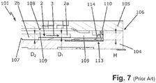
- FIG. 7 shows a longitudinal section through such a known push / pull card reader 101, in which a smart card 2 by the user in the insertion direction 3 via an insertion slot in the card reader 101 is inserted into its data exchange position and after the data exchange by the user again pulled out of the card reader 101.
- the smart card 2 carries a microchip (not shown) for storing the data, the contacts of which are provided as electrical contact pads (not shown) on the card surface.
- the card reader 101 has a card reader housing 106 composed of a housing lower part 104 and an upper housing part (housing cover) 105 .
- the bottom 107 of the housing base 104 and the ceiling 108 and two lateral guide walls (not shown) of the housing top 105 define a card slot 109 in the card reader housing 106 into which the card 3 is inserted in the insertion direction 3 into its data exchange position in which it is at an end stop 110 of the housing base 104 abuts.
- the housing lower part 104 has, for contacting the electrical contact fields of the chip card 2, a contacting unit (not shown) in the form of elastically deformable contact springs which project into the card path.
- the inserted chip card 2 deflects the contact springs out of the card path and then slides on the card surface until, in the data exchange position, they contact the electrical contact fields of the inserted chip card 2 for a data exchange.
- the lower housing part 104 supports the bottom 107 a Receiveendlagenschalter 113 having a switch lever 114, which at the end of the card slot 109 in the direction of the card slot height, ie in Fig. 7 upwards, protruding into the card slot 109.
- the shift lever 114 is deflected by a voltage applied to the end stop 110 chip card 2 from the card path, whereby the Receiveendlagenschalter 113 is switched, which in turn triggers the data exchange.
- the card thickness D1 of (as well as the not shown rear end of the card) in the card 3 card front end 2a is 0.76 ⁇ 0.08 mm with a standard card, and is smaller than in the middle card portion 2b whose card thickness D2 (by cards embossed on the card side Embossing) is increased to about 1.3-1.4 mm.
- the card slot height is reduced at least in the range of Receiveendlagenschalters to a height smaller than the card thickness of the thicker card section.
- the reduced height may, for example, correspond approximately to the mean value of the card thickness of the front card end and of the thicker card portion.
- the card slot height on both sides of the Receiveendlagenschalters in particular along the entire card slot width, at least in sections, reduced to the height smaller than the card thickness of the thicker card section.
- the reduced card chute height is advantageously approximately 1.0 mm, so that only objects with a thickness of max. 1 mm can trigger the card limit switch.
- the card end switch has a switch actuator projecting into the card slot at the end of the card slot towards the card slot height, e.g. a shift lever, open.
- a switch actuator projecting into the card slot at the end of the card slot towards the card slot height, e.g. a shift lever, open.
- the reduced card chute height may be formed by one or more separate pieces attached to the card reader housing and engaging the card slot or, preferably, at least one tab integrally formed on the card reader housing which engages the card slot and an abutment for the card slot introduced card forms.
- the at least one projection may be arranged on the lower housing part or on the upper housing part. In the case of a plurality of projections, the projections may also be arranged on both housing parts.
- the card slot can also be formed by at least one projection arranged on the card end position switch, in particular on a cover plate of the card end position switch, which engages in the card slot.
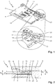
- the in FIGS. 1 and 2 shown card reader 1 is a so-called push / pull card reader, in which a smart card 2 is inserted by the user in the insertion direction 3 via an insertion slot in the card reader 1 to its data exchange position and after data exchange by the user again pulled out of the card reader 1.
- the smart card 2 carries a microchip (not shown) for storing the data, the contacts of which are provided as electrical contact pads (not shown) on the card surface.
- the card reader 1 has a card reader housing 6 composed of a housing lower part 4 and an upper housing part (housing cover) 5 ; Alternatively, the card reader housing 6 could also be made in one piece.
- the bottom 7 of the lower housing part 4 and the ceiling 8 and two lateral guide walls (not shown) of the upper housing part 5 define in the card reader housing 6 a card slot 9, in which the smart card 2 is inserted in the insertion direction 3 to its data exchange position in which they on one or , as shown, rests against a plurality of mutually aligned end stops 10 of the lower housing part 4.
- the housing lower part 4 has, for contacting the electrical contact pads of the chip card 2, a contacting unit 11 with eight contacts 12 , which are elastically deformable Contact springs are formed and arranged in two in the insertion direction 3 in a row, parallel rows are each grouped with four contacts.
- the contacts 12 protrude into the card path so that they are deflected by the inserted chip card 2 from the card path and then slide on the card surface until they contact the electrical contact fields of the inserted chip card 2 for data exchange in the data exchange position.
- the lower housing part 4 carries in the bottom 7 a Receiveendlagenschalter 13 with a shift lever 14 at the end of the card slot 9 in the direction of the card slot height, ie in Fig. 2 up, into the card slot 9 protrudes.
- the shift lever 14 is deflected by a voltage applied to the end stop 10 chip card 2 from the card path down, causing the Receiveendlagenschalter 13 is switched, which in turn triggers the data exchange.
- the card thickness D1 of (as well as the not shown rear end of the card) in the card 3 card front end 2a is 0.76 ⁇ 0.08 mm with a standard card, and is smaller than in the middle card portion 2b whose card thickness D2 (by cards embossed on the card side Embossing) is increased to about 1.3-1.4 mm.
- the slot width of the insertion slot, not shown here, and the card slot height H 1 are each about 1.55 mm.
- the card slot height H 2 in the region of the card end position switch 13 reduced to less than the card thickness D 2 of the thicker middle card portion 2 b, that is, for example, 1.0 mm.
- This reduced height H 2 is formed by an integrally formed on the bottom 7 of the housing part 4 projection 15 with upstream ramp, which engages laterally next to the shift lever 14 up in the card slot 9 and thus forms an abutment for the imported smart card 2.
- the projection 15 ensures that only objects with a thickness of max. 1 mm the shift lever 14 can trigger.
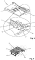
- FIGS. 1 and 2 is different in the FIGS. 3 and 4 card reader shown 1 in that here the reduced height H 2 is formed by two integrally formed on the ceiling 8 of the housing upper part 5 the projections 15 ', each having upstream bevels, which engage hook-shaped in the card slot 9 on both sides of the shift lever 14 and thus the counter bearing for the introduced Chip card 2 form.
- the projections 15 ' engage up in card slot 9, so that-as well as the card reader of FIGS. 1 and 2 -
- the inserted chip card 2 rests on the thrust bearing.
- Fig. 3 The two lateral guide walls 16 of the upper housing part 5 are also shown.
- FIGS. 1 and 2 is different in the Fig. 5 card reader shown 1 in that here the end of the card slot 9, the card slot height along the entire card slot width to the height H 2 is reduced, namely by a projection 15 and three further planar projections 17 upstanding on the bottom 8 of the lower housing part 4 and each have upstream ramps.
- the shift lever 14 is integrally formed on a punched cover plate 18 of the card end position switch 3.
- Fig. 6 shown modified Receiveendlagenschalter 13
- the reduced height H 2 is formed by two in the cover plate 18 stamped projections 15 " with upstream ramp, which are arranged on both sides of the shift lever 14.
Abstract
Bei einem Kartenleser (1) mit einer Kontaktiereinheit (11) zum Datenaustausch mit einer in einen Kartenschacht (9) des Karteniesers (1) eingeführten Karte (2), insbesondere Chipkarte, deren Kartendicke (D1, D2) an dem in Einführrichtung (3) vorderen Kartenende (2a) kleiner als an einem sich daran anschließenden, dickeren Kartenabschnitt (2b) ist, und mit einem Kartenendlagenschalter (13), der von einer bis zum Ende des Kartenschachts (9) eingeführten Karte (2) betätigt wird, ist erfindungsgemäß am Ende des Kartenschachts (9) die Kartenschachthöhe zumindest im Bereich des Kartenendlagensehalters (13) auf eine Höhe (H2) kleiner als die Kartendicke (D2) des dickeren Kartenabschnitts (2b) reduziert.

Description
Die vorliegende Erfindung betrifft einen Kartenleser mit einer Kontaktiereinheit zum Datenaustausch mit einer in einen Kartenschacht des Kartenlesers eingeführten Karte, insbesondere Chipkarte, deren Kartendicke an dem in Einführrichtung vorderen Kartenende kleiner als an einem sich daran anschließenden, dickeren Kartenabschnitt ist, und mit einem Kartenendlagenschalter, der von einer bis zum Ende des Kartenschachts eingeführten Karte betätigt wird.The present invention relates to a card reader with a contact unit for data exchange with an inserted into a card slot of the card reader card, in particular chip card whose card thickness is smaller at the front in the insertion direction card end than at an adjoining, thicker card section, and with a Kartenendlagenschalter, the from a card inserted to the end of the card slot.
Ein derartiger Kartenleser ist hinlänglich bekannt.
Der Kartenleser 101 weist ein aus einem Gehäuseunterteil 104 und einem Gehäuseoberteil (Gehäusedeckel) 105 zusammengesetztes Kartenlesergehäuse 106 auf. Der Boden 107 des Gehäuseunterteils 104 sowie die Decke 108 und zwei seitliche Führungswände (nicht gezeigt) des Gehäuseoberteils 105 definieren im Kartenlesergehäuse 106 einen Kartenschacht 109, in den die Karte 3 in Einführrichtung 3 bis in ihre Datenaustauschposition eingeschoben wird, in der sie an einem Endanschlag 110 des Gehäuseunterteils 104 anliegt. Das Gehäuseunterteil 104 weist zum Kontaktieren der elektrischen Kontaktfelder der Chipkarte 2 eine Kontaktiereinheit (nicht gezeigt) in Form von elastisch verformbaren Kontaktfedern auf, die in die Kartenbahn hineinragen. Durch die eingeführte Chipkarte 2 werden die Kontaktfedern aus der Kartenbahn ausgelenkt und gleiten dann auf der Kartenoberfläche, bis sie in der Datenaustauschposition die elektrischen Kontaktfelder der eingeführten Chipkarte 2 für einen Datenaustausch kontaktieren. Das Gehäuseunterteil 104 trägt im Boden 107 einen Kartenendlagenschalter 113 mit einem Schalthebel 114, der am Ende des Kartenschachts 109 in Richtung der Kartenschachthöhe, also in
Die Kartendicke D1 des in Karteneinführrichtung 3 vorderen Kartenendes 2a (wie auch am hier nicht gezeigten hinteren Kartenende) beträgt bei einer Standardkarte 0,76±0,08 mm und ist kleiner als im mittleren Kartenabschnitt 2b, dessen Kartendicke D2 durch Kartenprägungen auf der Kartenunterseite (Embossing) auf ca. 1,3-1,4 mm vergrößert ist. Der Einführschlitz des Kartenschachtes muss daher ca. 1,5 mm hoch sein, so dass aus Vandalismus oder zu Manipulationszwecken Gegenstände (Messer, Blechstreifen, usw.), deren vorderes Ende dicker als bei der Standardkarte (0,76+/-0,08 mm) ist, in den Kartenschacht 109 n(Schachthöhe H = 1,55 mm) eingeführt werden können und den Schalthebel 114 betätigen. Manche Kartenbenutzer kleben eine eingerissene Karte auch mit Tesafilm ab, wodurch sich in diesem Bereich die Kartendicke oft über 1,1 mm erhöht. Die Belastung des Schalthebels 114 ist aber nur für die Auslenkung durch das vordere Kartenende 2a ausgelegt, also nur für eine Karte mit einer Dicke von maximal 1,0-1,1 mm. Selbst nach einem Dauertest (650.000 Zyklen) mit einer Standardkarte ist keine negative Beeinträchtigung am Schalthebel 114 festzustellen. Wird jedoch ein Gegenstand mit einem vorderen Ende dicker als 1,1 mm eingeführt, wird der Schalthebel 114 plastisch verformt und somit der Schaltpunkt beeinträchtigt oder zerstört.The card thickness D1 of (as well as the not shown rear end of the card) in the
Es ist daher die Aufgabe der vorliegenden Erfindung, bei einem Kartenleser der eingangs genannten Art solche Beschädigungen des Kartenendlagenschalters zuverlässig zu verhindern.It is therefore an object of the present invention to reliably prevent such damage to the Kartenendlagenschalters in a card reader of the type mentioned.
Diese Aufgabe wird erfindungsgemäß dadurch gelöst, dass am Ende des Kartenschachts die Kartenschachthöhe zumindest im Bereich des Kartenendlagenschalters auf eine Höhe kleiner als die Kartendicke des dickeren Kartenabschnitts reduziert ist.This object is achieved in that at the end of the card slot, the card slot height is reduced at least in the range of Kartenendlagenschalters to a height smaller than the card thickness of the thicker card section.
Erfindungsgemäß können in den Bereich des Kartenendlagenschalters somit nur noch Gegenstände mit einem der reduzierten Kartenschachthöhe entsprechenden Dicke eingeführt werden, wodurch eine Schädigung des Kartenendlagenschalters durch übermäßige Auslenkung ausgeschlossen ist. Die reduzierte Höhe kann beispielsweise etwa dem Mittelwert der Kartendicke des vorderen Kartenendes und des dickeren Kartenabschnitts entsprechen.According to the invention, only objects with a thickness corresponding to the reduced card chute height can thus be introduced into the region of the card end position switch, whereby damage to the card end position switch due to excessive deflection is excluded. The reduced height may, for example, correspond approximately to the mean value of the card thickness of the front card end and of the thicker card portion.
Besonders bevorzugt ist die Kartenschachthöhe zu beiden Seiten des Kartenendlagenschalters, insbesondere entlang der gesamten Kartenschachtbreite zumindest abschnittweise, auf die Höhe kleiner als die Kartendicke des dickeren Kartenabschnitts reduziert.Particularly preferably, the card slot height on both sides of the Kartenendlagenschalters, in particular along the entire card slot width, at least in sections, reduced to the height smaller than the card thickness of the thicker card section.
Im Falle einer Standardkarte, deren beide Kartenenden eine Kartendicke von ca. 0,7-0,8 mm und deren dickerer, mittlerer Kartenabschnitt eine Kartendicke von 1,2-1,4 mm aufweist, beträgt die reduzierte Kartenschachthöhe vorteilhafterweise ca. 1,0 mm, so dass nur Gegenstände mit einer Dicke von max. 1 mm den Kartenendlagenschalter auslösen können.In the case of a standard card whose two card ends have a card thickness of approximately 0.7-0.8 mm and whose thicker, middle card portion has a card thickness of 1.2-1.4 mm, the reduced card chute height is advantageously approximately 1.0 mm, so that only objects with a thickness of max. 1 mm can trigger the card limit switch.
Vorzugsweise weist der Kartenendlagenschalter einen am Ende des Kartenschachts in Richtung der Kartenschachthöhe in den Kartenschacht hineinragenden Schaltbetätiger, z.B. einen Schalthebel, auf.Preferably, the card end switch has a switch actuator projecting into the card slot at the end of the card slot towards the card slot height, e.g. a shift lever, open.
Die reduzierte Kartenschachthöhe kann durch ein oder mehrere separate Teile, die am Kartenlesergehäuse befestigt sind und in den Kartenschacht eingreifen, oder aber, was bevorzugt ist, durch mindestens einen am Kartenlesergehäuse integral vorhandenen Vorsprung gebildet sein, der in den Kartenschacht eingreift und ein Gegenlager für die eingeführte Karte bildet.The reduced card chute height may be formed by one or more separate pieces attached to the card reader housing and engaging the card slot or, preferably, at least one tab integrally formed on the card reader housing which engages the card slot and an abutment for the card slot introduced card forms.
Bei einem Kartenlesergehäuse, das aus einem Gehäuseunterteil und einem Gehäuseoberteil zusammengesetzt ist, kann der mindestens eine Vorsprung am Gehäuseunterteil oder am Gehäuseoberteil angeordnet sein. Im Fall von mehreren Vorsprüngen können die Vorsprünge auch an beiden Gehäuseteilen angeordnet sein.In a card reader housing, which is composed of a lower housing part and an upper housing part, the at least one projection may be arranged on the lower housing part or on the upper housing part. In the case of a plurality of projections, the projections may also be arranged on both housing parts.
Alternativ oder zusätzlich zu den gehäuseseitigen Vorsprüngen kann der Kartenschacht auch durch mindestens einen am Kartenendlagenschalter, insbesondere an einem Abdeckblech des Kartenendlagenschalters, angeordneten Vorsprung gebildet sein, der in den Kartenschacht eingreift.As an alternative or in addition to the housing-side projections, the card slot can also be formed by at least one projection arranged on the card end position switch, in particular on a cover plate of the card end position switch, which engages in the card slot.
Weitere Vorteile der Erfindung ergeben sich aus der Beschreibung, den Ansprüchen und der Zeichnung. Ebenso können die vorstehend genannten und die noch weiter aufgeführten Merkmale je für sich oder zu mehreren in beliebigen Kombinationen Verwendung finden. Die gezeigten und beschriebenen Ausführungsformen sind nicht als abschließende Aufzählung zu verstehen, sondern haben vielmehr beispielhaften Charakter für die Schilderung der Erfindung.Further advantages of the invention will become apparent from the description, the claims and the drawings. Likewise, the features mentioned above and the features listed further can be used individually or in combination in any combination. The embodiments shown and described are not to be understood as exhaustive enumeration, but rather have exemplary character for the description of the invention.
Es zeigen:
- Fig. 1
- eine perspektivische Ansicht des Gehäuseunterteils eines ersten erfindungsgemäßen Kartenlesers mit einer vergrößerten Detailansicht eines Kartenendlagenschalters;
- Fig. 2
- einen Längsschnitt durch den in
Fig. 1 gezeigten Kartenleser im Bereich des Kartenendlagenschalters; - Fig. 3
- eine perspektivische Ansicht des Gehäuseoberteils eines zweiten erfindungsgemäßen Kartenlesers mit einer vergrößerten Detailansicht eines Kartenendlagenschalters;
- Fig. 4
- einen Längsschnitt durch den in
Fig. 3 gezeigten Kartenleser im Bereich des Kartenendlagenschalters; - Fig. 5
- eine perspektivische Ansicht des Gehäuseunterteils eines dritten erfindungsgemäßen Kartenlesers mit einer vergrößerten Detailansicht eines Kartenendlagenschalters;
- Fig. 6
- ein Abdeckblech eines modifizierten Kartenendlagenschalters; und
- Fig. 7
- einen Längsschnitt durch einen Kartenleser gemäß Stand der Technik im Bereich eines Kartenendlagenschalters.
- Fig. 1
- a perspective view of the housing bottom part of a first card reader according to the invention with an enlarged detail view of a Kartenendlagenschalters;
- Fig. 2
- a longitudinal section through the in
Fig. 1 shown card reader in the range of Kartenendlagenschalters; - Fig. 3
- a perspective view of the upper housing part of a second card reader according to the invention with an enlarged detail view of a Kartenendlagenschalters;
- Fig. 4
- a longitudinal section through the in
Fig. 3 shown card reader in the range of Kartenendlagenschalters; - Fig. 5
- a perspective view of the lower housing part of a third card reader according to the invention with an enlarged detail view of a Kartenendlagenschalters;
- Fig. 6
- a cover plate of a modified Kartenendlagenschalters; and
- Fig. 7
- a longitudinal section through a card reader according to the prior art in the range of Kartenendlagenschalters.
In der folgenden Beschreibung der Zeichnung werden für gleiche bzw. funktionsgleiche Bauteile identische Bezugszeichen verwendet.In the following description of the drawing, identical reference numerals are used for identical or functionally identical components.
Der in
Der Kartenleser 1 weist ein aus einem Gehäuseunterteil 4 und einem Gehäuseoberteil (Gehäusedeckel) 5 zusammengesetztes Kartenlesergehäuse 6 auf; alternativ könnte das Kartenlesergehäuse 6 aber auch einteilig ausgeführt sein. Der Boden 7 des Gehäuseunterteils 4 sowie die Decke 8 und zwei seitliche Führungswände (nicht gezeigt) des Gehäuseoberteils 5 definieren im Kartenlesergehäuse 6 einen Kartenschacht 9, in den die Chipkarte 2 in Einführrichtung 3 bis in ihre Datenaustauschposition eingeschoben wird, in der sie an einem oder, wie gezeigt, an mehreren, miteinander fluchtenden Endanschlägen 10 des Gehäuseunterteils 4 anliegt.The
Das Gehäuseunterteil 4 weist zum Kontaktieren der elektrischen Kontaktfelder der Chipkarte 2 eine Kontaktiereinheit 11 mit acht Kontakten 12 auf, die als elastisch verformbare Kontaktfedern ausgebildet und in zwei in Einführrichtung 3 hintereinander angeordneten, parallelen Reihen mit jeweils vier Kontakten gruppiert sind. Die Kontakte 12 ragen in die Kartenbahn hinein, so dass sie durch die eingeführte Chipkarte 2 aus der Kartenbahn ausgelenkt werden und dann auf der Kartenoberfläche gleiten, bis sie in der Datenaustauschposition die elektrischen Kontaktfelder der eingeführten Chipkarte 2 für einen Datenaustausch kontaktieren. Das Gehäuseunterteil 4 trägt im Boden 7 einen Kartenendlagenschalter 13 mit einem Schalthebel 14, der am Ende des Kartenschachts 9 in Richtung der Kartenschachthöhe, also in
Die Kartendicke D1 des in Karteneinführrichtung 3 vorderen Kartenendes 2a (wie auch am hier nicht gezeigten hinteren Kartenende) beträgt bei einer Standardkarte 0,76±0,08 mm und ist kleiner als im mittleren Kartenabschnitt 2b, dessen Kartendicke D2 durch Kartenprägungen auf der Kartenunterseite (Embossing) auf ca. 1,3-1,4 mm vergrößert ist. Zum Einführen einer Karte in den Kartenschacht 9 betragen daher die Schlitzbreite des hier nicht gezeigten Einführschlitzes und die Kartenschachthöhe H1 jeweils ca. 1,55 mm. Lediglich am Ende des Kartenschachts 9 ist die Kartenschachthöhe H2 im Bereich des Kartenendlagenschalters 13 auf kleiner als die Kartendicke D2 des dickeren mittleren Kartenabschnitts 2b reduziert, also beispielsweise auf 1,0 mm. Diese reduzierte Höhe H2 ist durch einen am Boden 7 des Gehäuseunterteils 4 integral ausgebildeten Vorsprung 15 mit vorgeordneter Auflaufschräge gebildet, der seitlich neben dem Schalthebel 14 nach oben in den Kartenschacht 9 eingreift und somit ein Gegenlager für die eingeführte Chipkarte 2 bildet. Durch den Vorsprung 15 ist sichergestellt, dass nur Gegenstände mit einer Dicke von max. 1 mm den Schalthebel 14 auslösen können.The card thickness D1 of (as well as the not shown rear end of the card) in the
Vom Kartenleser 1 der
Vom Kartenleser 1 der
Wie in
Claims (10)
dadurch gekennzeichnet,
dass am Ende des Kartenschachts (9) die Kartenschachthöhe zumindest im Bereich des Kartenendlagenschalters (13) auf eine Höhe (H2) kleiner als die Kartendicke (D2) des dickeren Kartenabschnitts (2b) reduziert ist.Card reader (1) with a contacting unit (11) for exchanging data with a card (2), in particular a chip card, inserted into a card slot (9) of the card reader (1), the card thickness (D 1 , D 2 ) of which is in the insertion direction (3). front card end (2a) is smaller than at a subsequent, thicker card portion (2b), and with a Kartenendlagenschalter (13) which is actuated by a to the end of the card slot (9) inserted card (2),
characterized,
that at the end of the card slot (9) the card slot height is reduced at least in the region of the card end position switch (13) to a height (H 2 ) smaller than the card thickness (D 2 ) of the thicker card portion (2b).
Priority Applications (1)
| Application Number | Priority Date | Filing Date | Title |
|---|---|---|---|
| EP17158668.8A EP3370184A1 (en) | 2017-03-01 | 2017-03-01 | Card reader with reduced thickness at the end position |
Applications Claiming Priority (1)
| Application Number | Priority Date | Filing Date | Title |
|---|---|---|---|
| EP17158668.8A EP3370184A1 (en) | 2017-03-01 | 2017-03-01 | Card reader with reduced thickness at the end position |
Publications (1)
| Publication Number | Publication Date |
|---|---|
| EP3370184A1 true EP3370184A1 (en) | 2018-09-05 |
Family
ID=58192245
Family Applications (1)
| Application Number | Title | Priority Date | Filing Date |
|---|---|---|---|
| EP17158668.8A Withdrawn EP3370184A1 (en) | 2017-03-01 | 2017-03-01 | Card reader with reduced thickness at the end position |
Country Status (1)
| Country | Link |
|---|---|
| EP (1) | EP3370184A1 (en) |
Citations (6)
| Publication number | Priority date | Publication date | Assignee | Title |
|---|---|---|---|---|
| US4904852A (en) * | 1986-12-12 | 1990-02-27 | Omron Tateisi Electronics Co. | IC card reader |
| US5949047A (en) * | 1994-09-07 | 1999-09-07 | Hitachi, Ltd. | Dust-proof portable IC card reader |
| US6086426A (en) * | 1998-03-03 | 2000-07-11 | Hon Hai Precision Ind. Co., Ltd. | Electrical connector |
| US6169257B1 (en) * | 1997-12-24 | 2001-01-02 | Itt Manufacturing Enterprises, Inc. | Smart card actuated dome contact switch |
| US20050017081A1 (en) * | 1997-06-04 | 2005-01-27 | Yoshio Kondo | Memory card, and receptacle for same |
| DE20122824U1 (en) * | 2001-06-20 | 2008-03-13 | Amphenol-Tuchel Electronics Gmbh | Smart card reader |
-
2017
- 2017-03-01 EP EP17158668.8A patent/EP3370184A1/en not_active Withdrawn
Patent Citations (6)
| Publication number | Priority date | Publication date | Assignee | Title |
|---|---|---|---|---|
| US4904852A (en) * | 1986-12-12 | 1990-02-27 | Omron Tateisi Electronics Co. | IC card reader |
| US5949047A (en) * | 1994-09-07 | 1999-09-07 | Hitachi, Ltd. | Dust-proof portable IC card reader |
| US20050017081A1 (en) * | 1997-06-04 | 2005-01-27 | Yoshio Kondo | Memory card, and receptacle for same |
| US6169257B1 (en) * | 1997-12-24 | 2001-01-02 | Itt Manufacturing Enterprises, Inc. | Smart card actuated dome contact switch |
| US6086426A (en) * | 1998-03-03 | 2000-07-11 | Hon Hai Precision Ind. Co., Ltd. | Electrical connector |
| DE20122824U1 (en) * | 2001-06-20 | 2008-03-13 | Amphenol-Tuchel Electronics Gmbh | Smart card reader |
Similar Documents
| Publication | Publication Date | Title |
|---|---|---|
| DE3645268C2 (en) | Card holder for a reader for a chip card | |
| DE3546780C2 (en) | Contact unit for chip card access | |
| DE3937383A1 (en) | RECEIVING DEVICE FOR CHIP CARDS | |
| EP1391968A2 (en) | Electrical contacting device, in particular for connecting a voltage source to an electronic circuit | |
| EP0580890A1 (en) | Holder for cards | |
| DE4334088C2 (en) | Multipole connector | |
| EP2659425B1 (en) | Smart card connector comprising a contact rocker | |
| DE102012005852B4 (en) | Switching spring assembly | |
| EP3370184A1 (en) | Card reader with reduced thickness at the end position | |
| EP1964024A2 (en) | Smart card connector comprising landing contacts and a cover spring as a card stopper | |
| EP1736910B1 (en) | Cardreader with symmetric spring contacts | |
| EP1924946A1 (en) | Smart card connector with shielding device for cards with a small pitch | |
| DE2558567C3 (en) | Slide switch | |
| DE102010030733B4 (en) | Card reader with discharge contacts | |
| DE10332583A1 (en) | Card connector assembly | |
| WO2000004486A1 (en) | Card reader for chip cards | |
| EP2323068A1 (en) | Card reader with blocker to prevent a card from being placed incorrectly | |
| DE2733800A1 (en) | Multiple contact relay with contacts laterally to magnetic coil - has all contacts distributed over coil length and at equal spacing from coil | |
| EP2290580B1 (en) | Card contacting device | |
| EP2201650B1 (en) | Push-push mechanism, particularly for a card reader | |
| EP0369231A2 (en) | Contacting device, particularly for LCD displays | |
| WO2018202655A1 (en) | Chip card reader having a start switch | |
| EP3026595B1 (en) | Card reader assembly | |
| EP1137107B1 (en) | Abutting connector | |
| EP1975853B1 (en) | Device for reading and/or writing cards |
Legal Events
| Date | Code | Title | Description |
|---|---|---|---|
| PUAI | Public reference made under article 153(3) epc to a published international application that has entered the european phase |
Free format text: ORIGINAL CODE: 0009012 |
|
| AK | Designated contracting states |
Kind code of ref document: A1 Designated state(s): AL AT BE BG CH CY CZ DE DK EE ES FI FR GB GR HR HU IE IS IT LI LT LU LV MC MK MT NL NO PL PT RO RS SE SI SK SM TR |
|
| AX | Request for extension of the european patent |
Extension state: BA ME |
|
| STAA | Information on the status of an ep patent application or granted ep patent |
Free format text: STATUS: THE APPLICATION IS DEEMED TO BE WITHDRAWN |
|
| 18D | Application deemed to be withdrawn |
Effective date: 20190306 |