EP3369602A1 - Display controller, display control method, and carrier means - Google Patents
Display controller, display control method, and carrier means Download PDFInfo
- Publication number
- EP3369602A1 EP3369602A1 EP18159476.3A EP18159476A EP3369602A1 EP 3369602 A1 EP3369602 A1 EP 3369602A1 EP 18159476 A EP18159476 A EP 18159476A EP 3369602 A1 EP3369602 A1 EP 3369602A1
- Authority
- EP
- European Patent Office
- Prior art keywords
- vision
- range
- prescribed
- data
- notification
- Prior art date
- Legal status (The legal status is an assumption and is not a legal conclusion. Google has not performed a legal analysis and makes no representation as to the accuracy of the status listed.)
- Withdrawn
Links
- 238000000034 method Methods 0.000 title claims abstract description 27
- 230000004438 eyesight Effects 0.000 claims abstract description 96
- 230000005043 peripheral vision Effects 0.000 claims abstract description 75
- 238000001514 detection method Methods 0.000 claims description 4
- 230000008569 process Effects 0.000 description 14
- 230000015654 memory Effects 0.000 description 12
- 238000010586 diagram Methods 0.000 description 9
- 230000003287 optical effect Effects 0.000 description 7
- 238000004891 communication Methods 0.000 description 4
- 230000006870 function Effects 0.000 description 4
- 230000007246 mechanism Effects 0.000 description 3
- 230000004044 response Effects 0.000 description 3
- 230000001502 supplementing effect Effects 0.000 description 3
- 230000009471 action Effects 0.000 description 2
- 230000005540 biological transmission Effects 0.000 description 2
- 230000004397 blinking Effects 0.000 description 2
- 239000003086 colorant Substances 0.000 description 2
- 230000001052 transient effect Effects 0.000 description 2
- 230000002411 adverse Effects 0.000 description 1
- 238000003491 array Methods 0.000 description 1
- 230000008859 change Effects 0.000 description 1
- 238000004590 computer program Methods 0.000 description 1
- 239000012050 conventional carrier Substances 0.000 description 1
- 230000000694 effects Effects 0.000 description 1
- 239000000284 extract Substances 0.000 description 1
- 238000003384 imaging method Methods 0.000 description 1
- 239000004973 liquid crystal related substance Substances 0.000 description 1
- 239000000203 mixture Substances 0.000 description 1
- 238000012986 modification Methods 0.000 description 1
- 230000004048 modification Effects 0.000 description 1
- 239000013307 optical fiber Substances 0.000 description 1
- 239000007787 solid Substances 0.000 description 1
Images


Classifications
-
- B—PERFORMING OPERATIONS; TRANSPORTING
- B60—VEHICLES IN GENERAL
- B60K—ARRANGEMENT OR MOUNTING OF PROPULSION UNITS OR OF TRANSMISSIONS IN VEHICLES; ARRANGEMENT OR MOUNTING OF PLURAL DIVERSE PRIME-MOVERS IN VEHICLES; AUXILIARY DRIVES FOR VEHICLES; INSTRUMENTATION OR DASHBOARDS FOR VEHICLES; ARRANGEMENTS IN CONNECTION WITH COOLING, AIR INTAKE, GAS EXHAUST OR FUEL SUPPLY OF PROPULSION UNITS IN VEHICLES
- B60K35/00—Instruments specially adapted for vehicles; Arrangement of instruments in or on vehicles
-
- G—PHYSICS
- G06—COMPUTING; CALCULATING OR COUNTING
- G06V—IMAGE OR VIDEO RECOGNITION OR UNDERSTANDING
- G06V20/00—Scenes; Scene-specific elements
- G06V20/50—Context or environment of the image
- G06V20/56—Context or environment of the image exterior to a vehicle by using sensors mounted on the vehicle
- G06V20/58—Recognition of moving objects or obstacles, e.g. vehicles or pedestrians; Recognition of traffic objects, e.g. traffic signs, traffic lights or roads
-
- B—PERFORMING OPERATIONS; TRANSPORTING
- B60—VEHICLES IN GENERAL
- B60K—ARRANGEMENT OR MOUNTING OF PROPULSION UNITS OR OF TRANSMISSIONS IN VEHICLES; ARRANGEMENT OR MOUNTING OF PLURAL DIVERSE PRIME-MOVERS IN VEHICLES; AUXILIARY DRIVES FOR VEHICLES; INSTRUMENTATION OR DASHBOARDS FOR VEHICLES; ARRANGEMENTS IN CONNECTION WITH COOLING, AIR INTAKE, GAS EXHAUST OR FUEL SUPPLY OF PROPULSION UNITS IN VEHICLES
- B60K35/00—Instruments specially adapted for vehicles; Arrangement of instruments in or on vehicles
- B60K35/10—Input arrangements, i.e. from user to vehicle, associated with vehicle functions or specially adapted therefor
-
- B—PERFORMING OPERATIONS; TRANSPORTING
- B60—VEHICLES IN GENERAL
- B60K—ARRANGEMENT OR MOUNTING OF PROPULSION UNITS OR OF TRANSMISSIONS IN VEHICLES; ARRANGEMENT OR MOUNTING OF PLURAL DIVERSE PRIME-MOVERS IN VEHICLES; AUXILIARY DRIVES FOR VEHICLES; INSTRUMENTATION OR DASHBOARDS FOR VEHICLES; ARRANGEMENTS IN CONNECTION WITH COOLING, AIR INTAKE, GAS EXHAUST OR FUEL SUPPLY OF PROPULSION UNITS IN VEHICLES
- B60K35/00—Instruments specially adapted for vehicles; Arrangement of instruments in or on vehicles
- B60K35/20—Output arrangements, i.e. from vehicle to user, associated with vehicle functions or specially adapted therefor
- B60K35/21—Output arrangements, i.e. from vehicle to user, associated with vehicle functions or specially adapted therefor using visual output, e.g. blinking lights or matrix displays
- B60K35/23—Head-up displays [HUD]
-
- B—PERFORMING OPERATIONS; TRANSPORTING
- B60—VEHICLES IN GENERAL
- B60K—ARRANGEMENT OR MOUNTING OF PROPULSION UNITS OR OF TRANSMISSIONS IN VEHICLES; ARRANGEMENT OR MOUNTING OF PLURAL DIVERSE PRIME-MOVERS IN VEHICLES; AUXILIARY DRIVES FOR VEHICLES; INSTRUMENTATION OR DASHBOARDS FOR VEHICLES; ARRANGEMENTS IN CONNECTION WITH COOLING, AIR INTAKE, GAS EXHAUST OR FUEL SUPPLY OF PROPULSION UNITS IN VEHICLES
- B60K35/00—Instruments specially adapted for vehicles; Arrangement of instruments in or on vehicles
- B60K35/20—Output arrangements, i.e. from vehicle to user, associated with vehicle functions or specially adapted therefor
- B60K35/28—Output arrangements, i.e. from vehicle to user, associated with vehicle functions or specially adapted therefor characterised by the type of the output information, e.g. video entertainment or vehicle dynamics information; characterised by the purpose of the output information, e.g. for attracting the attention of the driver
-
- B—PERFORMING OPERATIONS; TRANSPORTING
- B60—VEHICLES IN GENERAL
- B60K—ARRANGEMENT OR MOUNTING OF PROPULSION UNITS OR OF TRANSMISSIONS IN VEHICLES; ARRANGEMENT OR MOUNTING OF PLURAL DIVERSE PRIME-MOVERS IN VEHICLES; AUXILIARY DRIVES FOR VEHICLES; INSTRUMENTATION OR DASHBOARDS FOR VEHICLES; ARRANGEMENTS IN CONNECTION WITH COOLING, AIR INTAKE, GAS EXHAUST OR FUEL SUPPLY OF PROPULSION UNITS IN VEHICLES
- B60K35/00—Instruments specially adapted for vehicles; Arrangement of instruments in or on vehicles
- B60K35/20—Output arrangements, i.e. from vehicle to user, associated with vehicle functions or specially adapted therefor
- B60K35/29—Instruments characterised by the way in which information is handled, e.g. showing information on plural displays or prioritising information according to driving conditions
-
- B—PERFORMING OPERATIONS; TRANSPORTING
- B60—VEHICLES IN GENERAL
- B60K—ARRANGEMENT OR MOUNTING OF PROPULSION UNITS OR OF TRANSMISSIONS IN VEHICLES; ARRANGEMENT OR MOUNTING OF PLURAL DIVERSE PRIME-MOVERS IN VEHICLES; AUXILIARY DRIVES FOR VEHICLES; INSTRUMENTATION OR DASHBOARDS FOR VEHICLES; ARRANGEMENTS IN CONNECTION WITH COOLING, AIR INTAKE, GAS EXHAUST OR FUEL SUPPLY OF PROPULSION UNITS IN VEHICLES
- B60K35/00—Instruments specially adapted for vehicles; Arrangement of instruments in or on vehicles
- B60K35/60—Instruments characterised by their location or relative disposition in or on vehicles
-
- G—PHYSICS
- G02—OPTICS
- G02B—OPTICAL ELEMENTS, SYSTEMS OR APPARATUS
- G02B27/00—Optical systems or apparatus not provided for by any of the groups G02B1/00 - G02B26/00, G02B30/00
- G02B27/01—Head-up displays
- G02B27/0101—Head-up displays characterised by optical features
-
- G—PHYSICS
- G06—COMPUTING; CALCULATING OR COUNTING
- G06T—IMAGE DATA PROCESSING OR GENERATION, IN GENERAL
- G06T11/00—2D [Two Dimensional] image generation
-
- G—PHYSICS
- G08—SIGNALLING
- G08G—TRAFFIC CONTROL SYSTEMS
- G08G1/00—Traffic control systems for road vehicles
- G08G1/16—Anti-collision systems
- G08G1/166—Anti-collision systems for active traffic, e.g. moving vehicles, pedestrians, bikes
-
- B—PERFORMING OPERATIONS; TRANSPORTING
- B60—VEHICLES IN GENERAL
- B60K—ARRANGEMENT OR MOUNTING OF PROPULSION UNITS OR OF TRANSMISSIONS IN VEHICLES; ARRANGEMENT OR MOUNTING OF PLURAL DIVERSE PRIME-MOVERS IN VEHICLES; AUXILIARY DRIVES FOR VEHICLES; INSTRUMENTATION OR DASHBOARDS FOR VEHICLES; ARRANGEMENTS IN CONNECTION WITH COOLING, AIR INTAKE, GAS EXHAUST OR FUEL SUPPLY OF PROPULSION UNITS IN VEHICLES
- B60K2360/00—Indexing scheme associated with groups B60K35/00 or B60K37/00 relating to details of instruments or dashboards
- B60K2360/149—Instrument input by detecting viewing direction not otherwise provided for
-
- B—PERFORMING OPERATIONS; TRANSPORTING
- B60—VEHICLES IN GENERAL
- B60K—ARRANGEMENT OR MOUNTING OF PROPULSION UNITS OR OF TRANSMISSIONS IN VEHICLES; ARRANGEMENT OR MOUNTING OF PLURAL DIVERSE PRIME-MOVERS IN VEHICLES; AUXILIARY DRIVES FOR VEHICLES; INSTRUMENTATION OR DASHBOARDS FOR VEHICLES; ARRANGEMENTS IN CONNECTION WITH COOLING, AIR INTAKE, GAS EXHAUST OR FUEL SUPPLY OF PROPULSION UNITS IN VEHICLES
- B60K2360/00—Indexing scheme associated with groups B60K35/00 or B60K37/00 relating to details of instruments or dashboards
- B60K2360/16—Type of output information
- B60K2360/177—Augmented reality
-
- B—PERFORMING OPERATIONS; TRANSPORTING
- B60—VEHICLES IN GENERAL
- B60K—ARRANGEMENT OR MOUNTING OF PROPULSION UNITS OR OF TRANSMISSIONS IN VEHICLES; ARRANGEMENT OR MOUNTING OF PLURAL DIVERSE PRIME-MOVERS IN VEHICLES; AUXILIARY DRIVES FOR VEHICLES; INSTRUMENTATION OR DASHBOARDS FOR VEHICLES; ARRANGEMENTS IN CONNECTION WITH COOLING, AIR INTAKE, GAS EXHAUST OR FUEL SUPPLY OF PROPULSION UNITS IN VEHICLES
- B60K2360/00—Indexing scheme associated with groups B60K35/00 or B60K37/00 relating to details of instruments or dashboards
- B60K2360/16—Type of output information
- B60K2360/178—Warnings
-
- B—PERFORMING OPERATIONS; TRANSPORTING
- B60—VEHICLES IN GENERAL
- B60K—ARRANGEMENT OR MOUNTING OF PROPULSION UNITS OR OF TRANSMISSIONS IN VEHICLES; ARRANGEMENT OR MOUNTING OF PLURAL DIVERSE PRIME-MOVERS IN VEHICLES; AUXILIARY DRIVES FOR VEHICLES; INSTRUMENTATION OR DASHBOARDS FOR VEHICLES; ARRANGEMENTS IN CONNECTION WITH COOLING, AIR INTAKE, GAS EXHAUST OR FUEL SUPPLY OF PROPULSION UNITS IN VEHICLES
- B60K2360/00—Indexing scheme associated with groups B60K35/00 or B60K37/00 relating to details of instruments or dashboards
- B60K2360/18—Information management
- B60K2360/186—Displaying information according to relevancy
- B60K2360/1868—Displaying information according to relevancy according to driving situations
-
- B—PERFORMING OPERATIONS; TRANSPORTING
- B60—VEHICLES IN GENERAL
- B60K—ARRANGEMENT OR MOUNTING OF PROPULSION UNITS OR OF TRANSMISSIONS IN VEHICLES; ARRANGEMENT OR MOUNTING OF PLURAL DIVERSE PRIME-MOVERS IN VEHICLES; AUXILIARY DRIVES FOR VEHICLES; INSTRUMENTATION OR DASHBOARDS FOR VEHICLES; ARRANGEMENTS IN CONNECTION WITH COOLING, AIR INTAKE, GAS EXHAUST OR FUEL SUPPLY OF PROPULSION UNITS IN VEHICLES
- B60K2360/00—Indexing scheme associated with groups B60K35/00 or B60K37/00 relating to details of instruments or dashboards
- B60K2360/18—Information management
- B60K2360/191—Highlight information
-
- B—PERFORMING OPERATIONS; TRANSPORTING
- B60—VEHICLES IN GENERAL
- B60K—ARRANGEMENT OR MOUNTING OF PROPULSION UNITS OR OF TRANSMISSIONS IN VEHICLES; ARRANGEMENT OR MOUNTING OF PLURAL DIVERSE PRIME-MOVERS IN VEHICLES; AUXILIARY DRIVES FOR VEHICLES; INSTRUMENTATION OR DASHBOARDS FOR VEHICLES; ARRANGEMENTS IN CONNECTION WITH COOLING, AIR INTAKE, GAS EXHAUST OR FUEL SUPPLY OF PROPULSION UNITS IN VEHICLES
- B60K2360/00—Indexing scheme associated with groups B60K35/00 or B60K37/00 relating to details of instruments or dashboards
- B60K2360/20—Optical features of instruments
- B60K2360/33—Illumination features
- B60K2360/334—Projection means
-
- B—PERFORMING OPERATIONS; TRANSPORTING
- B60—VEHICLES IN GENERAL
- B60K—ARRANGEMENT OR MOUNTING OF PROPULSION UNITS OR OF TRANSMISSIONS IN VEHICLES; ARRANGEMENT OR MOUNTING OF PLURAL DIVERSE PRIME-MOVERS IN VEHICLES; AUXILIARY DRIVES FOR VEHICLES; INSTRUMENTATION OR DASHBOARDS FOR VEHICLES; ARRANGEMENTS IN CONNECTION WITH COOLING, AIR INTAKE, GAS EXHAUST OR FUEL SUPPLY OF PROPULSION UNITS IN VEHICLES
- B60K2360/00—Indexing scheme associated with groups B60K35/00 or B60K37/00 relating to details of instruments or dashboards
- B60K2360/77—Instrument locations other than the dashboard
- B60K2360/785—Instrument locations other than the dashboard on or in relation to the windshield or windows
-
- B—PERFORMING OPERATIONS; TRANSPORTING
- B60—VEHICLES IN GENERAL
- B60R—VEHICLES, VEHICLE FITTINGS, OR VEHICLE PARTS, NOT OTHERWISE PROVIDED FOR
- B60R2300/00—Details of viewing arrangements using cameras and displays, specially adapted for use in a vehicle
- B60R2300/20—Details of viewing arrangements using cameras and displays, specially adapted for use in a vehicle characterised by the type of display used
- B60R2300/205—Details of viewing arrangements using cameras and displays, specially adapted for use in a vehicle characterised by the type of display used using a head-up display
-
- B—PERFORMING OPERATIONS; TRANSPORTING
- B60—VEHICLES IN GENERAL
- B60R—VEHICLES, VEHICLE FITTINGS, OR VEHICLE PARTS, NOT OTHERWISE PROVIDED FOR
- B60R2300/00—Details of viewing arrangements using cameras and displays, specially adapted for use in a vehicle
- B60R2300/30—Details of viewing arrangements using cameras and displays, specially adapted for use in a vehicle characterised by the type of image processing
- B60R2300/301—Details of viewing arrangements using cameras and displays, specially adapted for use in a vehicle characterised by the type of image processing combining image information with other obstacle sensor information, e.g. using RADAR/LIDAR/SONAR sensors for estimating risk of collision
-
- B—PERFORMING OPERATIONS; TRANSPORTING
- B60—VEHICLES IN GENERAL
- B60R—VEHICLES, VEHICLE FITTINGS, OR VEHICLE PARTS, NOT OTHERWISE PROVIDED FOR
- B60R2300/00—Details of viewing arrangements using cameras and displays, specially adapted for use in a vehicle
- B60R2300/30—Details of viewing arrangements using cameras and displays, specially adapted for use in a vehicle characterised by the type of image processing
- B60R2300/304—Details of viewing arrangements using cameras and displays, specially adapted for use in a vehicle characterised by the type of image processing using merged images, e.g. merging camera image with stored images
- B60R2300/305—Details of viewing arrangements using cameras and displays, specially adapted for use in a vehicle characterised by the type of image processing using merged images, e.g. merging camera image with stored images merging camera image with lines or icons
-
- B—PERFORMING OPERATIONS; TRANSPORTING
- B60—VEHICLES IN GENERAL
- B60R—VEHICLES, VEHICLE FITTINGS, OR VEHICLE PARTS, NOT OTHERWISE PROVIDED FOR
- B60R2300/00—Details of viewing arrangements using cameras and displays, specially adapted for use in a vehicle
- B60R2300/30—Details of viewing arrangements using cameras and displays, specially adapted for use in a vehicle characterised by the type of image processing
- B60R2300/307—Details of viewing arrangements using cameras and displays, specially adapted for use in a vehicle characterised by the type of image processing virtually distinguishing relevant parts of a scene from the background of the scene
- B60R2300/308—Details of viewing arrangements using cameras and displays, specially adapted for use in a vehicle characterised by the type of image processing virtually distinguishing relevant parts of a scene from the background of the scene by overlaying the real scene, e.g. through a head-up display on the windscreen
-
- B—PERFORMING OPERATIONS; TRANSPORTING
- B60—VEHICLES IN GENERAL
- B60R—VEHICLES, VEHICLE FITTINGS, OR VEHICLE PARTS, NOT OTHERWISE PROVIDED FOR
- B60R2300/00—Details of viewing arrangements using cameras and displays, specially adapted for use in a vehicle
- B60R2300/60—Details of viewing arrangements using cameras and displays, specially adapted for use in a vehicle characterised by monitoring and displaying vehicle exterior scenes from a transformed perspective
- B60R2300/602—Details of viewing arrangements using cameras and displays, specially adapted for use in a vehicle characterised by monitoring and displaying vehicle exterior scenes from a transformed perspective with an adjustable viewpoint
- B60R2300/605—Details of viewing arrangements using cameras and displays, specially adapted for use in a vehicle characterised by monitoring and displaying vehicle exterior scenes from a transformed perspective with an adjustable viewpoint the adjustment being automatic
-
- B—PERFORMING OPERATIONS; TRANSPORTING
- B60—VEHICLES IN GENERAL
- B60R—VEHICLES, VEHICLE FITTINGS, OR VEHICLE PARTS, NOT OTHERWISE PROVIDED FOR
- B60R2300/00—Details of viewing arrangements using cameras and displays, specially adapted for use in a vehicle
- B60R2300/80—Details of viewing arrangements using cameras and displays, specially adapted for use in a vehicle characterised by the intended use of the viewing arrangement
- B60R2300/8093—Details of viewing arrangements using cameras and displays, specially adapted for use in a vehicle characterised by the intended use of the viewing arrangement for obstacle warning
-
- G—PHYSICS
- G02—OPTICS
- G02B—OPTICAL ELEMENTS, SYSTEMS OR APPARATUS
- G02B27/00—Optical systems or apparatus not provided for by any of the groups G02B1/00 - G02B26/00, G02B30/00
- G02B27/01—Head-up displays
- G02B27/0101—Head-up displays characterised by optical features
- G02B2027/0138—Head-up displays characterised by optical features comprising image capture systems, e.g. camera
-
- G—PHYSICS
- G02—OPTICS
- G02B—OPTICAL ELEMENTS, SYSTEMS OR APPARATUS
- G02B27/00—Optical systems or apparatus not provided for by any of the groups G02B1/00 - G02B26/00, G02B30/00
- G02B27/01—Head-up displays
- G02B27/0101—Head-up displays characterised by optical features
- G02B2027/0141—Head-up displays characterised by optical features characterised by the informative content of the display
Definitions
- Embodiments of the present disclosure relate to a display controller, a display control method, and a carrier means.
- heads-up displays that provide a driver with traffic information or dangerous object information by displaying an image on a front windshield are mounted in a car as on- vehicle equipment.
- a central vision and a peripheral vision are known in the art.
- the central vision has high spatial resolution, and is advantageous for object recognition.
- the peripheral vision is advantageous in supplementing the movement or position of an object.
- mechanisms to recognize what the object is without directing the line of vision to an object existing in the peripheral vision i.e., a mechanism in which the detailed information on an object existing in the peripheral vision is obtained and displayed in the central vision
- JP-2015-180037-A discloses a display control program, a display controller, and a display where the driver of a vehicle can recognize the category of an object existing in the peripheral vision without directing the line of vision to that object, for the purpose of increasing the successful rate in object recognition for the driver.
- the data is displayed on a display unit such as a heads-up display (HUD) in view of the characteristics of peripheral vision, but the driver cannot quickly respond to a dangerous object existing in the peripheral vision in order to avoid the danger.
- HUD heads-up display
- Embodiments of the present disclosure described herein provide a display controller, a display control method, and a carrier means.
- the display controller and the display control method include receiving (S101) foreground data used to recognize an object existing ahead of a vehicle in a direction of travel, receiving (S102) line-of-vision data from which line of vision of a driver of the vehicle is obtained, recognizing (S104) a prescribed object in the foreground data, determining (S105) whether the recognized prescribed object meets prescribed conditions, determining (S103) a range of central vision and a range of peripheral vision in the foreground data, using the line-of-vision data, determining (S106) in which one of the range of central vision and the range of peripheral vision the prescribed object that is determined to meet the prescribed conditions exists, and displaying (S107, S108) a notification for the prescribed object differently according to a result of the determining.
- the carrier means carries out the above display control method.
- a display controller where a driver can quickly react to a dangerous object existing in the peripheral vision can be provided.
- processors may be implemented as program modules or functional processes including routines, programs, objects, components, data structures, etc., that perform particular tasks or implement particular abstract data types and may be implemented using existing hardware at existing network elements or control nodes.
- Such existing hardware may include one or more central processing units (CPUs), digital signal processors (DSPs), application-specific-integrated-circuits (ASICs), field programmable gate arrays (FPGAs), computers or the like. These terms in general may be collectively referred to as processors.
- terms such as “processing” or “computing” or “calculating” or “determining” or “displaying” or the like refer to the action and processes of a computer system, or similar electronic computing device, that manipulates and transforms data represented as physical, electronic quantities within the computer system's registers and memories into other data similarly represented as physical quantities within the computer system memories or registers or other such information storage, transmission or display devices.
- a display controller determines, in the foreground data that is obtained by capturing an image ahead of the vehicle in the directions of travel, the range of central vision and the range of peripheral vision with reference to the line of vision of the driver. Moreover, the display controller generates, for a dangerous object existing in the peripheral vision, a danger notification different from notifications to dangerous objects existing in the central vision (for example, a dynamic notification), and superimposes and displays the generated danger notification on the dangerous object existing in the peripheral vision. Due to this configuration, the driver can be aware of the dangerous object at an earlier stage.
- the foreground data is used to recognize (detect) an object existing ahead of the vehicle in the directions of travel, and includes, for example, the image data that is obtained by capturing an image ahead of the vehicle in the directions of travel, and the data of the object detected by a detection device such as a radar and a sensor.
- a detection device such as a radar and a sensor.
- FIG. 10 is a schematic diagram illustrating a configuration of an entire system, according to the present embodiment
- the system includes a display controller 100, a front camera 201, a line-of-vision camera 202, an optical system including a mirror 203, and a laser beam source 204.
- the laser beam source 204 internally includes a plurality of light emitting elements, and those light emitting elements are display devices in which the timing of light emission or the light-emission intensity is controlled by the display controller 100.
- the front camera 201 captures an image of the sight ahead of the vehicle through a front windshield 200 of the vehicle.
- the line-of-vision camera 202 captures an image of an area around the eyes of the driver.
- the mirror 203 reflects the laser beams that are emitted from the laser beam source, and irradiates the front windshield 200 with the reflected laser beams.
- the system of FIG. 10 is configured as a heads-up display (HUD), which may be implemented by a panel system or a laser scanning system.
- HUD heads-up display
- an intermediate image is formed by an imaging device such as a liquid crystal panel, a digital micromirror device (DMD) panel (digital mirror device panel), or a vacuum fluorescent display (VFD).
- an imaging device such as a liquid crystal panel, a digital micromirror device (DMD) panel (digital mirror device panel), or a vacuum fluorescent display (VFD).
- DMD digital micromirror device
- VFD vacuum fluorescent display
- an intermediate image is formed by scanning a laser beam emitted from a laser beam source, using a two-dimensional scanning device.
- that light that corresponds to the image data generated by the display controller 100, output from the laser beam source 204, is directed to the optical system including the mirror 203.
- the optical system includes a screen that forms an intermediate image thereon with the light from the laser beam source 204. The light is then reflected by the mirror 203 toward the front windshield 200. Accordingly, the driver can visually recognize a virtual image, which is a magnified intermediate image, through the windshield 200.
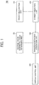
- FIG. 1 is a diagram illustrating a functional configuration of a display controller 100, according to a first embodiment of the present disclosure.
- the display controller 100 includes an object recognition unit 101, a danger prediction unit 102, a central vision/peripheral vision determining unit 103, a danger notification generation unit 104, and a display control unit 105.
- the display controller 100 is configured to receive a foreground image and line-of-vision data from which the line of vision of the driver can be obtained. For example, from the image of at least the eyes of the driver, the line-of-vision of the driver can be detected.
- the object recognition unit 101 receives the foreground image that is obtained by capturing an image ahead of the vehicle in the directions of travel with the front camera 201, and recognizes a prescribed object in the foreground image.
- the data of such a prescribed object (hereinafter, such data of a prescribed object may be referred to as "object data" where appropriate) is specified in advance, and is stored in a storage area of the display controller 100 or any storage area to which the object recognition unit 101 is accessible.
- the object recognition unit 101 specifies the position or relative velocity of the recognized object.
- the danger prediction unit 102 predicts whether the object recognized by the object recognition unit 101 is dangerous based on the data where dangerous objects are specified in advance.
- the term "prediction" in the present disclosure indicates determining whether or not prescribed conditions are met based on the data where dangerous objects are specified in advance.
- the data where dangerous objects are specified in advance (hereinafter, such data may be referred to as "dangerous object definition data" where appropriate) is stored in the danger prediction unit 102 or in a storage area within the display controller 100 to which the danger prediction unit 102 is accessible.
- the data where dangerous objects are specified may include, for example, the data (e.g., threshold) used to determine whether or not the recognized object is dangerous based on the position of the recognized object (i.e., the distance to the vehicle) or the relative velocity of the recognized object.
- the data where dangerous objects are specified may include data to change the priority level depending on the type of object (for example, a higher priority is given to a person over any vehicle).
- the central vision/peripheral vision determining unit 103 receives the line-of-vision data and the foreground image, and determines the range of central vision and the range of peripheral vision in the foreground image with reference to the line of vision of the driver.
- the danger notification generation unit 104 generates a danger notification depending on whether the object that is determined to be dangerous by the danger prediction unit 102 is in which of the range of central vision and the range of peripheral vision that are determined by the central vision/peripheral vision determining unit 103.
- the display control unit 105 controls the laser beam source such that the danger notification generated by the danger notification generation unit 104 is displayed.
- FIG. 2 is a flowchart of the processes of displaying a danger notification for one foreground image, according to the present embodiment.
- the display controller 100 scans the foreground image captured by the front camera 201 (step S101). On the other hand, the display controller 100 extracts the line-of-vision data of the driver from the image captured by the line-of-vision camera 202 (step S102). More specifically, in response to reception of the scanned foreground image from the front camera 201, the object recognition unit 101 starts operation to perform the step S101. In a similar manner, in response to reception of the extracted line-of-vision data from the line-of-vision camera 202, the central vision/peripheral vision determining unit 103 starts operation to perform the step S102.
- the central vision/peripheral vision determining unit 103 specifies to what point of the foreground image obtained in the step S101 the line of vision of the driver is directed to based on the line-of-vision data of the driver obtained in the step S102, and determines the range of central vision and the range of peripheral vision in the foreground image. Then, the central vision/peripheral vision determining unit 103 outputs the result of determining processes to the danger notification generation unit 104 (step S103).
- the object recognition unit 101 refers to the object data, and recognizes the existence or nonexistence of any one of the objects that are specified in advance in the foreground image obtained in the step S101 (step S104). When such an object exists ("YES" in the step S104), the object recognition unit 101 outputs the data of the recognized object to the danger prediction unit 102.
- the danger prediction unit 102 receives the data of the one or more recognized objects from the object recognition unit 101, and predicts whether or not each one of the recognized objects is dangerous referring to the dangerous object definition data (step S105). When at least one of the recognized objects is predicted to be dangerous for the vehicle ("YES" in the step S105), the danger prediction unit 102 outputs the data of such dangerous objects to the danger notification generation unit 104. When a plurality of dangerous objects are predicted by the danger prediction unit 102, the danger notification generation unit 104 repeats the processes in the steps S106 to S108 by the number of predicted dangerous objects.
- the danger notification generation unit 104 determines whether the dangerous object is in the range of central vision or in the range of peripheral vision based on the range of central vision and the range of peripheral vision in the foreground image (step S106). When the dangerous object is in the range of central vision ("YES" in the step S106), the danger notification generation unit 104 generates a danger notification for the central vision (step S107). When the dangerous object is in the range of peripheral vision ("NO" in the step S106), the danger notification generation unit 104 generates a danger notification for the peripheral vision (step S108).
- the display control unit 105 controls the laser beam source 204 (step S109) to emit a light to form an image based on the generated danger notification.
- the generated danger notification will be displayed on a predetermined area (called, display area) of the front windshield 200.
- the notification that is once output may be unchanged when the field of vision shifts.
- the display control unit 105 controls the laser beam source 204 to emit light to form an image, such that, when the image is displayed, the danger notification generated in the step S107 or the step S108 will overlap with the actual dangerous object in the foreground (step S109) through the windshield 200, and terminates the processes.
- the display controller 100 terminates the processes at that time.
- FIG. 2 depicts the processes for one foreground image.
- the display controller 100 When a plurality of consecutive foreground images are to be processed, the display controller 100 does not terminate the processes after the processes in the step S109, and returns the processes to the beginning.
- the display controller 100 is configured to generate and display a danger notification upon processing the multiple foreground images and the latest line-of-vision data obtained from the received multiple foreground images. For example, when a plurality of consecutive foreground images are to be processed, the display controller 100 generates a different danger notification for the same dangerous object according to the shift in the line of vision depending on whether the dangerous object is in the range of central vision or in the range of peripheral vision, and displays the generated danger notification.
- the central vision/peripheral vision determining unit 103 uses foreground images and the latest line-of-vision data, and determines the range of central vision or the range of peripheral vision in the foreground image with reference to the line of vision of the driver indicated by the line-of-vision data. It is desired that the display controller 100 be configured to store the previously received line-of-vision data (i.e., the latest line-of-vision data) in a storage area until new line-of-vision data is received. Due to this configuration, when the line of vision is shifted and the ranges of central vision and peripheral vision are changed, a danger notification can be altered and displayed depending on whether the dangerous object is in which of the central vision or the peripheral vision at that time, for the same dangerous object.
- the display controller 100 be configured to store the previously received line-of-vision data (i.e., the latest line-of-vision data) in a storage area until new line-of-vision data is received. Due to this configuration, when the line of vision is shifted and the ranges of central vision and
- the driver can make judgment and take an action appropriately in response to the dangerous object. Moreover, even when the position of the dangerous object shifts between the central vision and the peripheral vision due to the movement of a dangerous object or the shift of the line of vision of the driver, a different danger notification is generated depending on such shift. Accordingly, the driver can quickly notice and respond to a dangerous object existing anywhere in the foreground, and can avoid the danger.
- FIG. 3 and FIG. 4 are example images on which how the range of central vision and the range of peripheral vision are determined is indicated, according to the present embodiment.
- the range of central vision and the range of peripheral vision are determined as illustrated in FIG. 4 .
- the central vision has about 20 degrees in the up-and-down directions and the right and left directions with reference to the point to which the line of vision is directed
- the peripheral vision has about 130 degrees in the up-and-down directions and has about 180 degrees in the right and left directions. Accordingly, the central vision/peripheral vision determining unit 103 can determine the range if the point to which the line of vision is directed is known.
- some concrete examples of danger notification are described with reference to FIG. 5 to FIG. 7 . In the present embodiment, it is assumed that people and vehicles are defined as dangerous objects in advance in the dangerous object definition data due to this configuration.
- FIG. 5 and FIG. 6 are diagrams each illustrating a concrete danger notification for the central vision, according to the present embodiment.
- FIG. 5 is an example image on which the types of dangerous objects such as a person or a vehicle are indicated, according to the present embodiment.
- a circle with a white broken line indicates the range of central vision
- dangerous objects existing in the central vision for example, a red rectangle is generated for a person and a yellow circle is generated for a vehicle as danger notifications.
- the detailed information about dangerous objects are expressed by the shape or color of the danger notifications.
- FIG. 6 is an example image on which the types of risk of dangerous objects are indicated, according to the present embodiment.
- a danger notification is generated.
- the danger notification generation unit 104 may generate danger notifications with different shapes or colors depending on the types of dangerous objects and the level of risk. For example, dangerous objects of the same type may be classified into several groups depending on the level of risk. In particular, people who drive or ride a vehicle such as a motorbike or a bicycle may be distinguished from the other people who do not. As illustrated in FIG. 5 and FIG. 6 for example, additional information is displayed for dangerous objects. This configuration helps the driver to make more appropriate judgment.
- FIG. 7 is a diagram illustrating a concrete danger notification for the peripheral vision, according to the present embodiment.
- a circle with a white broken line indicates the range of central vision, for a dangerous object existing outside the central vision, that is, in the peripheral vision (where people and vehicles are targeted), the shape changes from circular to rectangular as a danger notification.
- a circle is indicated for a person riding on a motorbike on the image on the left, and a rectangle is indicated on the image the right side.
- a danger notification may express the movement, for example, by changes in size or by blinking.
- the danger notification generation unit 104 may generate a danger notification by one of or a combination of two or more of changes in shape, changes in size, blinking, or the like. As illustrated in FIG. 7 for example, a dynamic danger notification is displayed at the position where the dangerous object is in the range of peripheral vision. This configuration helps the driver to avoid danger quickly. When the field of vision of the driver shifts and the danger notification also changes accordingly, the display in the field of vision of the driver frequently changes. Such a configuration may affect the recognition of the driver. In view of the above circumstances, another method of generating one of a danger notification for the peripheral vision and a danger notification for the central vision, which is to avoid the above situation, is described.
- FIG. 8 is a flowchart of another set of processes of displaying a danger notification for one foreground image, according to the present embodiment.
- the danger prediction unit 102 receives the data of the recognized object from the object recognition unit 101, and predicts whether or not the recognized object is dangerous referring to the dangerous object definition data (S201). When at least one of the recognized objects is predicted to be dangerous for the vehicle (S201), regardless of whether the recognized dangerous object is placed in any of the peripheral vision or the central vision, the danger prediction unit 102 generates a danger notification for the central vision for the prescribed object in the central vision (step S202). The danger prediction unit 102 does not generate a danger notification for the prescribed object in the peripheral vision. However, when the target dangerous object continuously exists in the peripheral vision for a certain length of time (S203), the danger notification for the target dangerous object is switched from a danger notification for the central vision to a danger notification for the peripheral vision (S204).
- FIG. 9 is a diagram illustrating a hardware configuration of the display controller 100, according to the present embodiment.
- the display controller 100 includes a central processing unit (CPU) 111, a random access memory (RAM) 112, a read only memory (ROM) 113, a reader 114, a storage device 115, an external interface (I/F) 116, an input interface (I/F) 117, and an output interface (I/F) 118. Each of the elements is connected to a bus 119.
- CPU central processing unit
- RAM random access memory
- ROM read only memory
- reader 114 includes a storage device 115, an external interface (I/F) 116, an input interface (I/F) 117, and an output interface (I/F) 118.
- I/F external interface
- I/F input interface
- I/F output interface
- the CPU 111 executes various kinds of programs to control the entirety of the display controller 100. Moreover, the CPU 111 controls the laser beam source 204 illustrated in FIG. 10 according to a control program.
- the RAM 112 is a volatile storage medium where the data can be read and written at high speed, and serves as a work area when the CPU 111 executes the program.
- the ROM 113 is a read-only nonvolatile memory in which various kinds of programs or control programs are stored.
- the reader 114 is a device to read (receive) the images that are captured by the front camera 201 or the line-of-vision camera 202 as illustrated in FIG. 10 .
- the reader 114 outputs the scanned or extracted image and line-of-vision data to the object recognition unit 101 or to the central vision/peripheral vision determining unit 103. Note also that when the display controller 100 uses the detected data as the foreground data (as will be described later in detail as a second embodiment of the present disclosure), the reader 114 is configured to obtains data from the detection device in place of the front camera 201.
- the storage device 115 stores various kinds of programs, input image data, and various kinds of digital data to be processed, and is configured by, for example, a hard disk drive (HDD) and a flash memory.
- the external interface 116 is an interface (communication interface) that controls the connection to an external device or the transmission and reception of data, and communicates with an external device through the Ethernet (registered trademark) or the universal serial bus (USB).
- the input interface 117 is an operation unit that accepts instructions for the display controller 100 from a user, and is, for example, a touch panel, input buttons, or input keys.
- the output interface 118 is, for example, a display interface that outputs various kinds of information for display to a user.
- a program stored in a storage medium (such as the ROM 113 and the storage device 115) is read into the RAM 112, and the CPU 111 executes a set of instructions of the program.
- a storage medium such as the ROM 113 and the storage device 115
- the CPU 111 executes a set of instructions of the program.
- Some of or the entirety of the functional blocks of the display controller 100, as illustrated in FIG. 1 may be implemented by hardware.
- the functional blocks of the display controller 100 may be implemented by a combination of software and hardware, or alternatively, may be implemented by any one of hardware, firmware, and software, a combination of two or more of these hardware, firmware, and the software.
- Such a non-transitory computer readable medium includes various types of tangible storage medium, and may include, for example, a magnetic recording medium and a magneto-optical recording medium.
- a program may be distributed to a computer upon being stored in various types of transitory computer readable medium.
- Such a transitory computer readable medium may include, for example, an electrical signal, an optical signal, and an electromagnetic wave.
- a program can be distributed to a computer, using a transitory computer readable medium, through a cable communication channel such as a wire and an optical fiber or a wireless communication path.
- the display controller 100 may be configured to obtain predetermined object data or dangerous object definition data from an external recording medium or the network, through the external interface 116. Moreover, the display controller 100 may be configured such that a user can modify the predetermined object data or dangerous object definition data through the input interface 117.
- the display device is not limited to a laser beam source as long as the display device has a function of displaying an image on the front windshield 200.
- the display device may be a transmissive display.
- the foreground images that are captured by, for example, a camera are used as the foreground data.
- the detected data is used as the foreground data.
- the detected data is obtained by detecting or capturing data using a radar (for example, a millimeter-wave radar and a laser) that is used to recognize an object, a camera, and a detection device such as an optical sensor.
- a radar for example, a millimeter-wave radar and a laser
- an object is detected by detecting an electric wave that collides with an object and then is reflected.
- the object recognition unit 101 recognizes the presence of an object based on the detected data, and obtains data such as the position of the object and the relative velocity.
- the central vision/peripheral vision determining unit 103 can obtain the position of the object based on the detected data. Accordingly, the central vision/peripheral vision determining unit 103 can determine whether the object is in which one of the range of central vision and the range of the peripheral vision, using the line-of-vision data. Further, the danger prediction unit 102 can predict whether or not the object is dangerous based on the position of the object obtained from the detected data.
- the basic operation of the functional blocks of the display controller 100 is similar to that of the first embodiment. In addition to the foreground data as described above, the foreground data is satisfactory as long as the presence of an object is recognizable from such foreground data and the position of the object or the like is obtainable from such foreground data.
- a dynamic danger notification is superimposed and displayed on a dangerous object existing in the peripheral vision.
- danger notifications with different shapes or colors are superimposed and displayed on dangerous objects existing in the central vision, and a dynamic danger notification is superimposed and displayed on a dangerous object existing in the peripheral vision. Due to this configuration, the driver can sense where the danger is in the peripheral vision. Accordingly, the driver can quickly respond to a dangerous object existing in the peripheral vision, and can avoid the danger.
- any one of the above-described and other methods of the present invention may be embodied in the form of a computer program stored on any kind of storage medium.
- storage media include, but are not limited to, flexible disks, hard disks, optical discs, magneto-optical discs, magnetic tape, nonvolatile memory cards, ROM, etc.
- any one of the above-described and other methods of the present invention may be implemented by ASICs, prepared by interconnecting an appropriate network of conventional component circuits, or by a combination thereof with one or more conventional general-purpose microprocessors and/or signal processors programmed accordingly.
- the present invention can be implemented in any convenient form, for example using dedicated hardware, or a mixture of dedicated hardware and software.
- the present invention may be implemented as computer software implemented by one or more networked processing apparatuses.
- the network can comprise any conventional terrestrial or wireless communications network, such as the Internet.
- the processing apparatuses can compromise any suitably programmed apparatuses such as a general purpose computer, personal digital assistant, mobile telephone (such as a WAP or 3G-compliant phone) and so on. Since the present invention can be implemented as software, each and every aspect of the present invention thus encompasses computer software implementable on a programmable device.
- the computer software can be provided to the programmable device using any conventional carrier medium.
- the carrier medium can compromise a transient carrier medium such as an electrical, optical, microwave, acoustic or radio frequency signal carrying the computer code.
- a transient carrier medium such as an electrical, optical, microwave, acoustic or radio frequency signal carrying the computer code.
- An example of such a transient medium is a TCP/IP signal carrying computer code over an IP network, such as the Internet.
- the carrier medium can also comprise a storage medium for storing processor readable code such as a floppy disk, hard disk, CD ROM, magnetic tape device or solid state memory device.
- the hardware platform includes any desired kind of hardware resources including, for example, a CPU, a RAM, and a HDD.
- the CPU may be implemented by any desired kind of any desired number of processor.
- the RAM may be implemented by any desired kind of volatile or non-volatile memory.
- the HDD may be implemented by any desired kind of non-volatile memory capable of storing a large amount of data.
- the hardware resources may additionally include an input device, an output device, or a network device, depending on the type of the apparatus. Alternatively, the HDD may be provided outside of the apparatus as long as the HDD is accessible.
- the CPU such as a cache memory of the CPU
- the RAM may function as a physical memory or a primary memory of the apparatus, while the HDD may function as a secondary memory of the apparatus.
Landscapes
- Engineering & Computer Science (AREA)
- Physics & Mathematics (AREA)
- Mechanical Engineering (AREA)
- Chemical & Material Sciences (AREA)
- Combustion & Propulsion (AREA)
- Transportation (AREA)
- General Physics & Mathematics (AREA)
- Theoretical Computer Science (AREA)
- Optics & Photonics (AREA)
- Multimedia (AREA)
- Traffic Control Systems (AREA)
Abstract
Description
- Embodiments of the present disclosure relate to a display controller, a display control method, and a carrier means.
- Currently, heads-up displays that provide a driver with traffic information or dangerous object information by displaying an image on a front windshield are mounted in a car as on- vehicle equipment. As characteristics of human vision, a central vision and a peripheral vision are known in the art. The central vision has high spatial resolution, and is advantageous for object recognition. The peripheral vision is advantageous in supplementing the movement or position of an object. In view of such characteristics of vision, mechanisms to recognize what the object is without directing the line of vision to an object existing in the peripheral vision (i.e., a mechanism in which the detailed information on an object existing in the peripheral vision is obtained and displayed in the central vision) are known in the art.
- However, in the known mechanisms, when a dangerous object exists in the range of peripheral vision, the driver reacts to such a dangerous object after the detailed information that is obtained and displayed in the central vision is recognized, and it is difficult to react to such a dangerous object quickly in order to avoid the danger.
- For example,
JP-2015-180037-A JP-2015-180037-A - Embodiments of the present disclosure described herein provide a display controller, a display control method, and a carrier means. The display controller and the display control method include receiving (S101) foreground data used to recognize an object existing ahead of a vehicle in a direction of travel, receiving (S102) line-of-vision data from which line of vision of a driver of the vehicle is obtained, recognizing (S104) a prescribed object in the foreground data, determining (S105) whether the recognized prescribed object meets prescribed conditions, determining (S103) a range of central vision and a range of peripheral vision in the foreground data, using the line-of-vision data, determining (S106) in which one of the range of central vision and the range of peripheral vision the prescribed object that is determined to meet the prescribed conditions exists, and displaying (S107, S108) a notification for the prescribed object differently according to a result of the determining. The carrier means carries out the above display control method.
- According to one aspect of the present disclosure, a display controller where a driver can quickly react to a dangerous object existing in the peripheral vision can be provided.
- A more complete appreciation of exemplary embodiments and the many attendant advantages thereof will be readily obtained as the same becomes better understood by reference to the following detailed description when considered in connection with the accompanying drawings.
-
FIG. 1 is a diagram illustrating a functional configuration of a display controller, according to an embodiment of the present disclosure. -
FIG. 2 is a flowchart of the processes of displaying a danger notification for one foreground image, according to an embodiment of the present disclosure. -
FIG. 3 is an example foreground image and a line of vision indicated thereon, according to an embodiment of the present disclosure. -
FIG. 4 is an example image on which how the range of central vision and the range of peripheral vision are determined is indicated, according to an embodiment of the present disclosure. -
FIG. 5 is an example image on which danger notifications for central vision are indicated, according to an embodiment of the present disclosure. -
FIG. 6 is another example image on which danger notifications for central vision are indicated, according to an embodiment of the present disclosure. -
FIG. 7 is a diagram illustrating example images on which danger notifications for peripheral vision are indicated, according to an embodiment of the present disclosure. -
FIG. 8 is a flowchart of another set of processes of displaying a danger notification for one foreground image, according to an embodiment of the present disclosure. -
FIG. 9 is a diagram illustrating a hardware configuration of a display controller, according to an embodiment of the present disclosure. -
FIG. 10 is a schematic diagram illustrating a configuration of an entire system, according to an embodiment of the present disclosure. - The accompanying drawings are intended to depict exemplary embodiments of the present disclosure and should not be interpreted to limit the scope thereof. The accompanying drawings are not to be considered as drawn to scale unless explicitly noted.
- The terminology used herein is for the purpose of describing particular embodiments only and is not intended to be limiting of the present disclosure. As used herein, the singular forms "a", "an" and "the" are intended to include the plural forms as well, unless the context clearly indicates otherwise. It will be further understood that the terms "includes" and/or "including", when used in this specification, specify the presence of stated features, integers, steps, operations, elements, and/or components, but do not preclude the presence or addition of one or more other features, integers, steps, operations, elements, components, and/or groups thereof.
- In describing example embodiments shown in the drawings, specific terminology is employed for the sake of clarity. However, the present disclosure is not intended to be limited to the specific terminology so selected and it is to be understood that each specific element includes all technical equivalents that have the same structure, operate in a similar manner, and achieve a similar result.
- In the following description, illustrative embodiments will be described with reference to acts and symbolic representations of operations (e.g., in the form of flowcharts) that may be implemented as program modules or functional processes including routines, programs, objects, components, data structures, etc., that perform particular tasks or implement particular abstract data types and may be implemented using existing hardware at existing network elements or control nodes. Such existing hardware may include one or more central processing units (CPUs), digital signal processors (DSPs), application-specific-integrated-circuits (ASICs), field programmable gate arrays (FPGAs), computers or the like. These terms in general may be collectively referred to as processors.
- Unless specifically stated otherwise, or as is apparent from the discussion, terms such as "processing" or "computing" or "calculating" or "determining" or "displaying" or the like, refer to the action and processes of a computer system, or similar electronic computing device, that manipulates and transforms data represented as physical, electronic quantities within the computer system's registers and memories into other data similarly represented as physical quantities within the computer system memories or registers or other such information storage, transmission or display devices.
- Some embodiments of the present disclosure are described below with reference to the drawings. Note that like reference signs denote like elements among the drawings for purposes of simplification. A display controller according to an embodiment of the present disclosure determines, in the foreground data that is obtained by capturing an image ahead of the vehicle in the directions of travel, the range of central vision and the range of peripheral vision with reference to the line of vision of the driver. Moreover, the display controller generates, for a dangerous object existing in the peripheral vision, a danger notification different from notifications to dangerous objects existing in the central vision (for example, a dynamic notification), and superimposes and displays the generated danger notification on the dangerous object existing in the peripheral vision. Due to this configuration, the driver can be aware of the dangerous object at an earlier stage. The foreground data is used to recognize (detect) an object existing ahead of the vehicle in the directions of travel, and includes, for example, the image data that is obtained by capturing an image ahead of the vehicle in the directions of travel, and the data of the object detected by a detection device such as a radar and a sensor. In the following description, an embodiment of the present disclosure is described in detail with reference to the drawings.
- In the first embodiment, cases in which the foreground image that is obtained by capturing an image ahead of the vehicle in the directions of travel is used as image data are described.
-
FIG. 10 is a schematic diagram illustrating a configuration of an entire system, according to the present embodiment - The system includes a
display controller 100, afront camera 201, a line-of-vision camera 202, an optical system including amirror 203, and a laser beam source 204. The laser beam source 204 internally includes a plurality of light emitting elements, and those light emitting elements are display devices in which the timing of light emission or the light-emission intensity is controlled by thedisplay controller 100. Thefront camera 201 captures an image of the sight ahead of the vehicle through afront windshield 200 of the vehicle. The line-of-vision camera 202 captures an image of an area around the eyes of the driver. Themirror 203 reflects the laser beams that are emitted from the laser beam source, and irradiates thefront windshield 200 with the reflected laser beams. - In one embodiment, the system of
FIG. 10 is configured as a heads-up display (HUD), which may be implemented by a panel system or a laser scanning system. In the panel system, an intermediate image is formed by an imaging device such as a liquid crystal panel, a digital micromirror device (DMD) panel (digital mirror device panel), or a vacuum fluorescent display (VFD). In the laser scanning system, an intermediate image is formed by scanning a laser beam emitted from a laser beam source, using a two-dimensional scanning device. - More specifically, in this example, that light that corresponds to the image data generated by the
display controller 100, output from the laser beam source 204, is directed to the optical system including themirror 203. In one example, the optical system includes a screen that forms an intermediate image thereon with the light from the laser beam source 204. The light is then reflected by themirror 203 toward thefront windshield 200. Accordingly, the driver can visually recognize a virtual image, which is a magnified intermediate image, through thewindshield 200. -
FIG. 1 is a diagram illustrating a functional configuration of adisplay controller 100, according to a first embodiment of the present disclosure. - The
display controller 100 includes anobject recognition unit 101,adanger prediction unit 102, a central vision/peripheralvision determining unit 103, a dangernotification generation unit 104, and adisplay control unit 105. Thedisplay controller 100 is configured to receive a foreground image and line-of-vision data from which the line of vision of the driver can be obtained. For example, from the image of at least the eyes of the driver, the line-of-vision of the driver can be detected. - The
object recognition unit 101 receives the foreground image that is obtained by capturing an image ahead of the vehicle in the directions of travel with thefront camera 201, and recognizes a prescribed object in the foreground image. The data of such a prescribed object (hereinafter, such data of a prescribed object may be referred to as "object data" where appropriate) is specified in advance, and is stored in a storage area of thedisplay controller 100 or any storage area to which theobject recognition unit 101 is accessible. Moreover, theobject recognition unit 101 specifies the position or relative velocity of the recognized object. Thedanger prediction unit 102 predicts whether the object recognized by theobject recognition unit 101 is dangerous based on the data where dangerous objects are specified in advance. The term "prediction" in the present disclosure indicates determining whether or not prescribed conditions are met based on the data where dangerous objects are specified in advance. The data where dangerous objects are specified in advance (hereinafter, such data may be referred to as "dangerous object definition data" where appropriate) is stored in thedanger prediction unit 102 or in a storage area within thedisplay controller 100 to which thedanger prediction unit 102 is accessible. The data where dangerous objects are specified may include, for example, the data (e.g., threshold) used to determine whether or not the recognized object is dangerous based on the position of the recognized object (i.e., the distance to the vehicle) or the relative velocity of the recognized object. Moreover, the data where dangerous objects are specified may include data to change the priority level depending on the type of object (for example, a higher priority is given to a person over any vehicle). - The central vision/peripheral
vision determining unit 103 receives the line-of-vision data and the foreground image, and determines the range of central vision and the range of peripheral vision in the foreground image with reference to the line of vision of the driver. The dangernotification generation unit 104 generates a danger notification depending on whether the object that is determined to be dangerous by thedanger prediction unit 102 is in which of the range of central vision and the range of peripheral vision that are determined by the central vision/peripheralvision determining unit 103. Thedisplay control unit 105 controls the laser beam source such that the danger notification generated by the dangernotification generation unit 104 is displayed. -
FIG. 2 is a flowchart of the processes of displaying a danger notification for one foreground image, according to the present embodiment. - The
display controller 100 scans the foreground image captured by the front camera 201 (step S101). On the other hand, thedisplay controller 100 extracts the line-of-vision data of the driver from the image captured by the line-of-vision camera 202 (step S102). More specifically, in response to reception of the scanned foreground image from thefront camera 201, theobject recognition unit 101 starts operation to perform the step S101. In a similar manner, in response to reception of the extracted line-of-vision data from the line-of-vision camera 202, the central vision/peripheralvision determining unit 103 starts operation to perform the step S102. - The central vision/peripheral
vision determining unit 103 specifies to what point of the foreground image obtained in the step S101 the line of vision of the driver is directed to based on the line-of-vision data of the driver obtained in the step S102, and determines the range of central vision and the range of peripheral vision in the foreground image. Then, the central vision/peripheralvision determining unit 103 outputs the result of determining processes to the danger notification generation unit 104 (step S103). Theobject recognition unit 101 refers to the object data, and recognizes the existence or nonexistence of any one of the objects that are specified in advance in the foreground image obtained in the step S101 (step S104). When such an object exists ("YES" in the step S104), theobject recognition unit 101 outputs the data of the recognized object to thedanger prediction unit 102. - The
danger prediction unit 102 receives the data of the one or more recognized objects from theobject recognition unit 101, and predicts whether or not each one of the recognized objects is dangerous referring to the dangerous object definition data (step S105). When at least one of the recognized objects is predicted to be dangerous for the vehicle ("YES" in the step S105), thedanger prediction unit 102 outputs the data of such dangerous objects to the dangernotification generation unit 104. When a plurality of dangerous objects are predicted by thedanger prediction unit 102, the dangernotification generation unit 104 repeats the processes in the steps S106 to S108 by the number of predicted dangerous objects. The dangernotification generation unit 104 determines whether the dangerous object is in the range of central vision or in the range of peripheral vision based on the range of central vision and the range of peripheral vision in the foreground image (step S106). When the dangerous object is in the range of central vision ("YES" in the step S106), the dangernotification generation unit 104 generates a danger notification for the central vision (step S107). When the dangerous object is in the range of peripheral vision ("NO" in the step S106), the dangernotification generation unit 104 generates a danger notification for the peripheral vision (step S108). Thedisplay control unit 105 controls the laser beam source 204 (step S109) to emit a light to form an image based on the generated danger notification. Accordingly, the generated danger notification will be displayed on a predetermined area (called, display area) of thefront windshield 200. The notification that is once output may be unchanged when the field of vision shifts. Thedisplay control unit 105 controls the laser beam source 204 to emit light to form an image, such that, when the image is displayed, the danger notification generated in the step S107 or the step S108 will overlap with the actual dangerous object in the foreground (step S109) through thewindshield 200, and terminates the processes. - When the
object recognition unit 101 does not recognize any one of the objects that are specified in advance in the foreground image ("NO" in the step S104), or when there is no dangerous object at all for the vehicle among the objects predicted by the danger prediction unit 102 ("NO" in the step S105), thedisplay controller 100 terminates the processes at that time. -
FIG. 2 depicts the processes for one foreground image. - When a plurality of consecutive foreground images are to be processed, the
display controller 100 does not terminate the processes after the processes in the step S109, and returns the processes to the beginning. - In order to handle a plurality of foreground images, when a plurality of foreground images are received, the
display controller 100 is configured to generate and display a danger notification upon processing the multiple foreground images and the latest line-of-vision data obtained from the received multiple foreground images. For example, when a plurality of consecutive foreground images are to be processed, thedisplay controller 100 generates a different danger notification for the same dangerous object according to the shift in the line of vision depending on whether the dangerous object is in the range of central vision or in the range of peripheral vision, and displays the generated danger notification. More specifically, the central vision/peripheralvision determining unit 103 uses foreground images and the latest line-of-vision data, and determines the range of central vision or the range of peripheral vision in the foreground image with reference to the line of vision of the driver indicated by the line-of-vision data. It is desired that thedisplay controller 100 be configured to store the previously received line-of-vision data (i.e., the latest line-of-vision data) in a storage area until new line-of-vision data is received. Due to this configuration, when the line of vision is shifted and the ranges of central vision and peripheral vision are changed, a danger notification can be altered and displayed depending on whether the dangerous object is in which of the central vision or the peripheral vision at that time, for the same dangerous object. Accordingly, even if the line of vision is shifted, the driver can make judgment and take an action appropriately in response to the dangerous object. Moreover, even when the position of the dangerous object shifts between the central vision and the peripheral vision due to the movement of a dangerous object or the shift of the line of vision of the driver, a different danger notification is generated depending on such shift. Accordingly, the driver can quickly notice and respond to a dangerous object existing anywhere in the foreground, and can avoid the danger. -
FIG. 3 and FIG. 4 are example images on which how the range of central vision and the range of peripheral vision are determined is indicated, according to the present embodiment. - When the image of
FIG. 3 is successfully obtained as the foreground image of the vehicle and the line of vision of the driver is directed to the position at which a sign "x" is set, the range of central vision and the range of peripheral vision are determined as illustrated inFIG. 4 . It is commonly known in the art that the central vision has about 20 degrees in the up-and-down directions and the right and left directions with reference to the point to which the line of vision is directed, and it is also known in the art that the peripheral vision has about 130 degrees in the up-and-down directions and has about 180 degrees in the right and left directions. Accordingly, the central vision/peripheralvision determining unit 103 can determine the range if the point to which the line of vision is directed is known. Next, some concrete examples of danger notification are described with reference toFIG. 5 to FIG. 7 . In the present embodiment, it is assumed that people and vehicles are defined as dangerous objects in advance in the dangerous object definition data due to this configuration. -
FIG. 5 andFIG. 6 are diagrams each illustrating a concrete danger notification for the central vision, according to the present embodiment. -
FIG. 5 is an example image on which the types of dangerous objects such as a person or a vehicle are indicated, according to the present embodiment. When the inside of a circle with a white broken line indicates the range of central vision, for dangerous objects existing in the central vision (where people and vehicles are targeted), for example, a red rectangle is generated for a person and a yellow circle is generated for a vehicle as danger notifications. In view of the characteristics that the central vision is advantageous for object recognition, the detailed information about dangerous objects are expressed by the shape or color of the danger notifications. -
FIG. 6 is an example image on which the types of risk of dangerous objects are indicated, according to the present embodiment. - When the inside of a circle with a white broken line indicates the range of central vision, for example, a high-risk object (i.e., a person in the present embodiment) is surrounded by a "red circle", and a low-risk object is surrounded by a "yellow circle" for the dangerous objects existing in the central vision. By so doing, a danger notification is generated. Alternatively, the danger
notification generation unit 104 may generate danger notifications with different shapes or colors depending on the types of dangerous objects and the level of risk. For example, dangerous objects of the same type may be classified into several groups depending on the level of risk. In particular, people who drive or ride a vehicle such as a motorbike or a bicycle may be distinguished from the other people who do not. As illustrated inFIG. 5 andFIG. 6 for example, additional information is displayed for dangerous objects. This configuration helps the driver to make more appropriate judgment. -
FIG. 7 is a diagram illustrating a concrete danger notification for the peripheral vision, according to the present embodiment. - When the inside of a circle with a white broken line indicates the range of central vision, for a dangerous object existing outside the central vision, that is, in the peripheral vision (where people and vehicles are targeted), the shape changes from circular to rectangular as a danger notification. In
FIG. 7 , a circle is indicated for a person riding on a motorbike on the image on the left, and a rectangle is indicated on the image the right side. In view of the characteristics that the peripheral vision is advantageous in supplementing the movement or position of an object, where the risk is at is expressed by the movement of the danger notification. Alternatively, a danger notification may express the movement, for example, by changes in size or by blinking. Alternatively, as a dynamic danger notification, the dangernotification generation unit 104 may generate a danger notification by one of or a combination of two or more of changes in shape, changes in size, blinking, or the like. As illustrated inFIG. 7 for example, a dynamic danger notification is displayed at the position where the dangerous object is in the range of peripheral vision. This configuration helps the driver to avoid danger quickly. When the field of vision of the driver shifts and the danger notification also changes accordingly, the display in the field of vision of the driver frequently changes. Such a configuration may affect the recognition of the driver. In view of the above circumstances, another method of generating one of a danger notification for the peripheral vision and a danger notification for the central vision, which is to avoid the above situation, is described. -
FIG. 8 is a flowchart of another set of processes of displaying a danger notification for one foreground image, according to the present embodiment. - The
danger prediction unit 102 receives the data of the recognized object from theobject recognition unit 101, and predicts whether or not the recognized object is dangerous referring to the dangerous object definition data (S201). When at least one of the recognized objects is predicted to be dangerous for the vehicle (S201), regardless of whether the recognized dangerous object is placed in any of the peripheral vision or the central vision, thedanger prediction unit 102 generates a danger notification for the central vision for the prescribed object in the central vision (step S202). Thedanger prediction unit 102 does not generate a danger notification for the prescribed object in the peripheral vision. However, when the target dangerous object continuously exists in the peripheral vision for a certain length of time (S203), the danger notification for the target dangerous object is switched from a danger notification for the central vision to a danger notification for the peripheral vision (S204). In this flow ofFIG. 8 , even when the field of vision of the driver shifts and moves to the range of central vision, when the danger notification for the dangerous object has been switched to a danger notification for the peripheral vision, such a danger notification for the peripheral vision remains unchanged and is not switched to a danger notification for the central vision. Due to this configuration, even when the field of vision of the driver shifts, the switching between the central vision and the peripheral vision does not occur frequently, and the adverse effect on the recognition of the driver, which could be caused by frequent changes between the central vision and the peripheral vision, can be reduced. -
FIG. 9 is a diagram illustrating a hardware configuration of thedisplay controller 100, according to the present embodiment. - The
display controller 100 includes a central processing unit (CPU) 111, a random access memory (RAM) 112, a read only memory (ROM) 113, areader 114, astorage device 115, an external interface (I/F) 116, an input interface (I/F) 117, and an output interface (I/F) 118. Each of the elements is connected to abus 119. - The
CPU 111 executes various kinds of programs to control the entirety of thedisplay controller 100. Moreover, theCPU 111 controls the laser beam source 204 illustrated inFIG. 10 according to a control program. TheRAM 112 is a volatile storage medium where the data can be read and written at high speed, and serves as a work area when theCPU 111 executes the program. TheROM 113 is a read-only nonvolatile memory in which various kinds of programs or control programs are stored. Thereader 114 is a device to read (receive) the images that are captured by thefront camera 201 or the line-of-vision camera 202 as illustrated inFIG. 10 . Thereader 114 outputs the scanned or extracted image and line-of-vision data to theobject recognition unit 101 or to the central vision/peripheralvision determining unit 103. Note also that when thedisplay controller 100 uses the detected data as the foreground data (as will be described later in detail as a second embodiment of the present disclosure), thereader 114 is configured to obtains data from the detection device in place of thefront camera 201. - The
storage device 115 stores various kinds of programs, input image data, and various kinds of digital data to be processed, and is configured by, for example, a hard disk drive (HDD) and a flash memory. Theexternal interface 116 is an interface (communication interface) that controls the connection to an external device or the transmission and reception of data, and communicates with an external device through the Ethernet (registered trademark) or the universal serial bus (USB). Theinput interface 117 is an operation unit that accepts instructions for thedisplay controller 100 from a user, and is, for example, a touch panel, input buttons, or input keys. Theoutput interface 118 is, for example, a display interface that outputs various kinds of information for display to a user. - In order to implement the functions of the
display controller 100 as described above by executing a program, in thedisplay controller 100 as illustrated inFIG. 9 , a program stored in a storage medium (such as theROM 113 and the storage device 115) is read into theRAM 112, and theCPU 111 executes a set of instructions of the program. Some of or the entirety of the functional blocks of thedisplay controller 100, as illustrated inFIG. 1 , may be implemented by hardware. For example, like an embedded system, the functional blocks of thedisplay controller 100 may be implemented by a combination of software and hardware, or alternatively, may be implemented by any one of hardware, firmware, and software, a combination of two or more of these hardware, firmware, and the software. - When the entirety of or some of the
display controller 100 is implemented by a program, such a program may be distributed to a computer upon being stored in various types of non-transitory computer readable medium. Such a non-transitory computer readable medium includes various types of tangible storage medium, and may include, for example, a magnetic recording medium and a magneto-optical recording medium. Alternatively, a program may be distributed to a computer upon being stored in various types of transitory computer readable medium. Such a transitory computer readable medium may include, for example, an electrical signal, an optical signal, and an electromagnetic wave. A program can be distributed to a computer, using a transitory computer readable medium, through a cable communication channel such as a wire and an optical fiber or a wireless communication path. - The
display controller 100 may be configured to obtain predetermined object data or dangerous object definition data from an external recording medium or the network, through theexternal interface 116. Moreover, thedisplay controller 100 may be configured such that a user can modify the predetermined object data or dangerous object definition data through theinput interface 117. In the present disclosure, the display device is not limited to a laser beam source as long as the display device has a function of displaying an image on thefront windshield 200. For example, the display device may be a transmissive display. - In the first embodiment, cases in which the foreground images that are captured by, for example, a camera are used as the foreground data are described. By contrast, in the present embodiment, cases in which the detected data is used as the foreground data are described. The detected data is obtained by detecting or capturing data using a radar (for example, a millimeter-wave radar and a laser) that is used to recognize an object, a camera, and a detection device such as an optical sensor. For example, when a radar is used, an object is detected by detecting an electric wave that collides with an object and then is reflected.
- When the
display controller 100 receives the detected data, theobject recognition unit 101 recognizes the presence of an object based on the detected data, and obtains data such as the position of the object and the relative velocity. The central vision/peripheralvision determining unit 103 can obtain the position of the object based on the detected data. Accordingly, the central vision/peripheralvision determining unit 103 can determine whether the object is in which one of the range of central vision and the range of the peripheral vision, using the line-of-vision data. Further, thedanger prediction unit 102 can predict whether or not the object is dangerous based on the position of the object obtained from the detected data. The basic operation of the functional blocks of thedisplay controller 100 is similar to that of the first embodiment. In addition to the foreground data as described above, the foreground data is satisfactory as long as the presence of an object is recognizable from such foreground data and the position of the object or the like is obtainable from such foreground data. - In the preferred embodiments of the present disclosure as described above, in view of the characteristics that the peripheral vision is advantageous in supplementing the movement or position of an object, a dynamic danger notification is superimposed and displayed on a dangerous object existing in the peripheral vision. For example, in the
display controller 100, danger notifications with different shapes or colors are superimposed and displayed on dangerous objects existing in the central vision, and a dynamic danger notification is superimposed and displayed on a dangerous object existing in the peripheral vision. Due to this configuration, the driver can sense where the danger is in the peripheral vision. Accordingly, the driver can quickly respond to a dangerous object existing in the peripheral vision, and can avoid the danger. - Numerous additional modifications and variations are possible in light of the above teachings. It is therefore to be understood that within the scope of the appended claims, the disclosure of the present invention may be practiced otherwise than as specifically described herein. For example, elements and/or features of different illustrative embodiments may be combined with each other and/or substituted for each other within the scope of this disclosure and appended claims.
- Further, as described above, any one of the above-described and other methods of the present invention may be embodied in the form of a computer program stored on any kind of storage medium. Examples of storage media include, but are not limited to, flexible disks, hard disks, optical discs, magneto-optical discs, magnetic tape, nonvolatile memory cards, ROM, etc. Alternatively, any one of the above-described and other methods of the present invention may be implemented by ASICs, prepared by interconnecting an appropriate network of conventional component circuits, or by a combination thereof with one or more conventional general-purpose microprocessors and/or signal processors programmed accordingly.
- The present invention can be implemented in any convenient form, for example using dedicated hardware, or a mixture of dedicated hardware and software. The present invention may be implemented as computer software implemented by one or more networked processing apparatuses. The network can comprise any conventional terrestrial or wireless communications network, such as the Internet. The processing apparatuses can compromise any suitably programmed apparatuses such as a general purpose computer, personal digital assistant, mobile telephone (such as a WAP or 3G-compliant phone) and so on. Since the present invention can be implemented as software, each and every aspect of the present invention thus encompasses computer software implementable on a programmable device. The computer software can be provided to the programmable device using any conventional carrier medium. The carrier medium can compromise a transient carrier medium such as an electrical, optical, microwave, acoustic or radio frequency signal carrying the computer code. An example of such a transient medium is a TCP/IP signal carrying computer code over an IP network, such as the Internet. The carrier medium can also comprise a storage medium for storing processor readable code such as a floppy disk, hard disk, CD ROM, magnetic tape device or solid state memory device.
- The hardware platform includes any desired kind of hardware resources including, for example, a CPU, a RAM, and a HDD. The CPU may be implemented by any desired kind of any desired number of processor. The RAM may be implemented by any desired kind of volatile or non-volatile memory. The HDD may be implemented by any desired kind of non-volatile memory capable of storing a large amount of data. The hardware resources may additionally include an input device, an output device, or a network device, depending on the type of the apparatus. Alternatively, the HDD may be provided outside of the apparatus as long as the HDD is accessible. In this example, the CPU, such as a cache memory of the CPU, and the RAM may function as a physical memory or a primary memory of the apparatus, while the HDD may function as a secondary memory of the apparatus.
Claims (8)
- A display controller (100) comprising:a reader unit (114) configured to receive foreground data used to recognize an object existing ahead of a vehicle in a direction of travel and line-of-vision data from which line of vision of a driver of the vehicle is obtained;an object recognition unit (101) configured to recognize a prescribed object in the foreground data;a danger prediction unit (102) configured to determine whether the recognized prescribed object meets prescribed conditions;a central vision/peripheral vision determining unit (103) configured to determine a range of central vision and a range of peripheral vision in the foreground data, using the line-of-vision data; anda display control unit (105) configured to determine in which one of the range of central vision and the range of peripheral vision the prescribed object that is determined to meet the prescribed conditions by the danger prediction unit (102) exists, and to display a notification for the prescribed object differently according to a result of determination made by the danger prediction unit (102).
- The display controller (100) according to claim 1, wherein
when the prescribed object that is determined to meet the prescribed conditions exists in the range of central vision, the display control unit (105) generates a notification for the central vision for the prescribed object that is determined to meet the prescribed conditions by the danger prediction unit (102) for display, and
when the prescribed object that is determined to meet the prescribed conditions by the danger prediction unit (102) exists in the range of peripheral vision for a certain length of time or longer, the display control unit (105) generates a notification for the peripheral vision for the prescribed object, and switches from a display of the notification for the central vision to a display of the notification for the peripheral vision. - The display controller (100) according to claim 1 or 2, wherein
when the prescribed object exists in the range of central vision, the display control unit (105) generates a notification where at least one of shape and color varies according to a type of the prescribed object, and
when the prescribed object exists in the range of peripheral vision, the display control unit (105) controls not to generate a notification. - The display controller (100) according to any one of claims 1 to 3, wherein
when the prescribed object exists in the range of central vision, the display control unit (105) generates a notification where at least one of shape and color varies according to a level of risk of the prescribed object, and
when the prescribed object exists in the range of peripheral vision, the display control unit (105) controls not to generate a notification. - The display controller (100) according to any one of claims 1 to 4, wherein when the foreground data is received a plurality of times, the central vision/peripheral vision determining unit (103) determines the range of central vision and the range of peripheral vision, using latest line-of-vision data obtained from received multiple foreground images.
- The display controller (100) according to any one of claims 1 to 5, wherein the foreground data includes at least one of image data obtained by capturing an image ahead of the vehicle in the direction of travel and data of the prescribed object detected by a detection device.
- A method for controlling display, comprising:receiving (S101) foreground data used to recognize an object existing ahead of a vehicle in a direction of travel;receiving (S102) line-of-vision data from which line of vision of a driver of the vehicle is obtained;recognizing (S104) a prescribed object in the foreground data;determining (S105) whether the recognized prescribed object meets prescribed conditions;determining (S103) a range of central vision and a range of peripheral vision in the foreground data, using the line-of-vision data;determining (S106) in which one of the range of central vision and the range of peripheral vision the prescribed object that is determined to meet the prescribed conditions exists; anddisplaying (S107, S108) a notification for the prescribed object differently according to a result of the determining.
- A carrier means carrying computer readable code for controlling a computer system to carry out the method of claim 7.
Applications Claiming Priority (2)
| Application Number | Priority Date | Filing Date | Title |
|---|---|---|---|
| JP2017039123 | 2017-03-02 | ||
| JP2018034335A JP7067116B2 (en) | 2017-03-02 | 2018-02-28 | Display control device, display control method and display control program |
Publications (1)
| Publication Number | Publication Date |
|---|---|
| EP3369602A1 true EP3369602A1 (en) | 2018-09-05 |
Family
ID=61563159
Family Applications (1)
| Application Number | Title | Priority Date | Filing Date |
|---|---|---|---|
| EP18159476.3A Withdrawn EP3369602A1 (en) | 2017-03-02 | 2018-03-01 | Display controller, display control method, and carrier means |
Country Status (2)
| Country | Link |
|---|---|
| US (1) | US10354153B2 (en) |
| EP (1) | EP3369602A1 (en) |
Families Citing this family (3)
| Publication number | Priority date | Publication date | Assignee | Title |
|---|---|---|---|---|
| JP6713591B1 (en) * | 2019-04-17 | 2020-06-24 | 楽天株式会社 | Display control device, display control method, program, and non-transitory computer-readable information recording medium |
| JP2021149309A (en) * | 2020-03-17 | 2021-09-27 | ソニーグループ株式会社 | Information processing device, information processing method, and computer program |
| US11462021B2 (en) * | 2021-01-13 | 2022-10-04 | GM Global Technology Operations LLC | Obstacle detection and notification for motorcycles |
Citations (5)
| Publication number | Priority date | Publication date | Assignee | Title |
|---|---|---|---|---|
| JP2003291688A (en) * | 2002-04-03 | 2003-10-15 | Denso Corp | Display method, driving support device and program |
| JP2012148710A (en) * | 2011-01-20 | 2012-08-09 | Toyota Motor Corp | Image display apparatus |
| JP2012212351A (en) * | 2011-03-31 | 2012-11-01 | Mazda Motor Corp | Vehicle information providing device |
| JP2015180037A (en) | 2014-02-25 | 2015-10-08 | パナソニックIpマネジメント株式会社 | Display control program, display control device and display device |
| US20160082840A1 (en) * | 2013-09-13 | 2016-03-24 | Hitachi Maxell, Ltd. | Information display system and information display device |
Family Cites Families (6)
| Publication number | Priority date | Publication date | Assignee | Title |
|---|---|---|---|---|
| KR20130090932A (en) * | 2005-06-03 | 2013-08-14 | 프레자코르, 인크. | Compositions comprising elemental metals and uses therefor |
| JP2011193324A (en) | 2010-03-16 | 2011-09-29 | Ricoh Co Ltd | Onboard imaging apparatus |
| JP5406328B2 (en) | 2012-03-27 | 2014-02-05 | 株式会社デンソーアイティーラボラトリ | VEHICLE DISPLAY DEVICE, ITS CONTROL METHOD AND PROGRAM |
| EP3007048A4 (en) * | 2013-05-29 | 2017-01-25 | Mitsubishi Electric Corporation | Information display device |
| US20150116197A1 (en) * | 2013-10-24 | 2015-04-30 | Johnson Controls Technology Company | Systems and methods for displaying three-dimensional images on a vehicle instrument console |
| US20150175068A1 (en) * | 2013-12-20 | 2015-06-25 | Dalila Szostak | Systems and methods for augmented reality in a head-up display |
-
2018
- 2018-03-01 EP EP18159476.3A patent/EP3369602A1/en not_active Withdrawn
- 2018-03-01 US US15/908,928 patent/US10354153B2/en not_active Expired - Fee Related
Patent Citations (5)
| Publication number | Priority date | Publication date | Assignee | Title |
|---|---|---|---|---|
| JP2003291688A (en) * | 2002-04-03 | 2003-10-15 | Denso Corp | Display method, driving support device and program |
| JP2012148710A (en) * | 2011-01-20 | 2012-08-09 | Toyota Motor Corp | Image display apparatus |
| JP2012212351A (en) * | 2011-03-31 | 2012-11-01 | Mazda Motor Corp | Vehicle information providing device |
| US20160082840A1 (en) * | 2013-09-13 | 2016-03-24 | Hitachi Maxell, Ltd. | Information display system and information display device |
| JP2015180037A (en) | 2014-02-25 | 2015-10-08 | パナソニックIpマネジメント株式会社 | Display control program, display control device and display device |
Also Published As
| Publication number | Publication date |
|---|---|
| US10354153B2 (en) | 2019-07-16 |
| US20180253611A1 (en) | 2018-09-06 |
Similar Documents
| Publication | Publication Date | Title |
|---|---|---|
| US11308809B2 (en) | Collision control method and apparatus, and storage medium | |
| US11468581B2 (en) | Distance measurement method, intelligent control method, electronic device, and storage medium | |
| CN110419211B (en) | Information processing apparatus, information processing method, and computer-readable storage medium | |
| EP3252658B1 (en) | Information processing apparatus and information processing method | |
| US10699486B2 (en) | Display system, information presentation system, control method of display system, storage medium, and mobile body | |
| US20180201227A1 (en) | Vehicle environment imaging systems and methods | |
| US11527077B2 (en) | Advanced driver assist system, method of calibrating the same, and method of detecting object in the same | |
| US9785845B2 (en) | Drive support display device | |
| JP2023542992A (en) | Intelligent drive control method and device, vehicle, electronic equipment and storage medium | |
| EP3369602A1 (en) | Display controller, display control method, and carrier means | |
| CN113370911B (en) | Pose adjustment method, device, equipment and medium of vehicle-mounted sensor | |
| US9715633B2 (en) | Vehicle-mounted image processing device | |
| EP2963633A1 (en) | Object sensing device | |
| CN112580571A (en) | Vehicle running control method and device and electronic equipment | |
| CN111507973B (en) | Target detection method and device, electronic equipment and storage medium | |
| JP2017062638A (en) | Image recognition processing device and program | |
| US9652988B2 (en) | Display control device, display control method, and non-transitory computer-readable storage medium | |
| KR20210052525A (en) | Method and apparatus for recognizing indication information of indicator light, electronic device and storage medium | |
| US10325508B2 (en) | Apparatus and associated methods for collision avoidance | |
| US11325472B2 (en) | Line-of-sight guidance device | |
| WO2016159364A1 (en) | Pedestrian determination device | |
| US20210008981A1 (en) | Control device, display device, display system, moving body, control method, and recording medium | |
| JP2018147481A (en) | Display controller, display control method, and display control program | |
| JP2021149641A (en) | Object presentation device and object presentation method | |
| CN113160590B (en) | Control method and device of intelligent automobile and related equipment |
Legal Events
| Date | Code | Title | Description |
|---|---|---|---|
| PUAI | Public reference made under article 153(3) epc to a published international application that has entered the european phase |
Free format text: ORIGINAL CODE: 0009012 |
|
| STAA | Information on the status of an ep patent application or granted ep patent |
Free format text: STATUS: REQUEST FOR EXAMINATION WAS MADE |
|
| 17P | Request for examination filed |
Effective date: 20180301 |
|
| AK | Designated contracting states |
Kind code of ref document: A1 Designated state(s): AL AT BE BG CH CY CZ DE DK EE ES FI FR GB GR HR HU IE IS IT LI LT LU LV MC MK MT NL NO PL PT RO RS SE SI SK SM TR |
|
| AX | Request for extension of the european patent |
Extension state: BA ME |
|
| RAP1 | Party data changed (applicant data changed or rights of an application transferred) |
Owner name: RICOH COMPANY, LTD. |
|
| STAA | Information on the status of an ep patent application or granted ep patent |
Free format text: STATUS: EXAMINATION IS IN PROGRESS |
|
| STAA | Information on the status of an ep patent application or granted ep patent |
Free format text: STATUS: EXAMINATION IS IN PROGRESS |
|
| 17Q | First examination report despatched |
Effective date: 20201211 |
|
| STAA | Information on the status of an ep patent application or granted ep patent |
Free format text: STATUS: EXAMINATION IS IN PROGRESS |
|
| STAA | Information on the status of an ep patent application or granted ep patent |
Free format text: STATUS: THE APPLICATION IS DEEMED TO BE WITHDRAWN |
|
| 18D | Application deemed to be withdrawn |
Effective date: 20220727 |