EP3369145B1 - Multipolar connector - Google Patents
Multipolar connector Download PDFInfo
- Publication number
- EP3369145B1 EP3369145B1 EP16798557.1A EP16798557A EP3369145B1 EP 3369145 B1 EP3369145 B1 EP 3369145B1 EP 16798557 A EP16798557 A EP 16798557A EP 3369145 B1 EP3369145 B1 EP 3369145B1
- Authority
- EP
- European Patent Office
- Prior art keywords
- socket
- plug
- contacts
- connector
- connector according
- Prior art date
- Legal status (The legal status is an assumption and is not a legal conclusion. Google has not performed a legal analysis and makes no representation as to the accuracy of the status listed.)
- Active
Links
- 239000012528 membrane Substances 0.000 claims description 8
- 230000008878 coupling Effects 0.000 claims description 3
- 238000010168 coupling process Methods 0.000 claims description 3
- 238000005859 coupling reaction Methods 0.000 claims description 3
- 239000004744 fabric Substances 0.000 description 3
- 230000010354 integration Effects 0.000 description 2
- 238000004140 cleaning Methods 0.000 description 1
- 239000004020 conductor Substances 0.000 description 1
- 238000010292 electrical insulation Methods 0.000 description 1
- 230000001939 inductive effect Effects 0.000 description 1
- 239000002184 metal Substances 0.000 description 1
- 238000000465 moulding Methods 0.000 description 1
- 230000005405 multipole Effects 0.000 description 1
- 239000002245 particle Substances 0.000 description 1
- 230000000284 resting effect Effects 0.000 description 1
- 230000008054 signal transmission Effects 0.000 description 1
- 230000002747 voluntary effect Effects 0.000 description 1
Images


Classifications
-
- H—ELECTRICITY
- H01—ELECTRIC ELEMENTS
- H01R—ELECTRICALLY-CONDUCTIVE CONNECTIONS; STRUCTURAL ASSOCIATIONS OF A PLURALITY OF MUTUALLY-INSULATED ELECTRICAL CONNECTING ELEMENTS; COUPLING DEVICES; CURRENT COLLECTORS
- H01R24/00—Two-part coupling devices, or either of their cooperating parts, characterised by their overall structure
- H01R24/38—Two-part coupling devices, or either of their cooperating parts, characterised by their overall structure having concentrically or coaxially arranged contacts
-
- H—ELECTRICITY
- H01—ELECTRIC ELEMENTS
- H01R—ELECTRICALLY-CONDUCTIVE CONNECTIONS; STRUCTURAL ASSOCIATIONS OF A PLURALITY OF MUTUALLY-INSULATED ELECTRICAL CONNECTING ELEMENTS; COUPLING DEVICES; CURRENT COLLECTORS
- H01R13/00—Details of coupling devices of the kinds covered by groups H01R12/70 or H01R24/00 - H01R33/00
- H01R13/02—Contact members
- H01R13/22—Contacts for co-operating by abutting
- H01R13/24—Contacts for co-operating by abutting resilient; resiliently-mounted
- H01R13/2407—Contacts for co-operating by abutting resilient; resiliently-mounted characterized by the resilient means
-
- H—ELECTRICITY
- H01—ELECTRIC ELEMENTS
- H01R—ELECTRICALLY-CONDUCTIVE CONNECTIONS; STRUCTURAL ASSOCIATIONS OF A PLURALITY OF MUTUALLY-INSULATED ELECTRICAL CONNECTING ELEMENTS; COUPLING DEVICES; CURRENT COLLECTORS
- H01R13/00—Details of coupling devices of the kinds covered by groups H01R12/70 or H01R24/00 - H01R33/00
- H01R13/46—Bases; Cases
- H01R13/52—Dustproof, splashproof, drip-proof, waterproof, or flameproof cases
- H01R13/5205—Sealing means between cable and housing, e.g. grommet
-
- H—ELECTRICITY
- H01—ELECTRIC ELEMENTS
- H01R—ELECTRICALLY-CONDUCTIVE CONNECTIONS; STRUCTURAL ASSOCIATIONS OF A PLURALITY OF MUTUALLY-INSULATED ELECTRICAL CONNECTING ELEMENTS; COUPLING DEVICES; CURRENT COLLECTORS
- H01R13/00—Details of coupling devices of the kinds covered by groups H01R12/70 or H01R24/00 - H01R33/00
- H01R13/46—Bases; Cases
- H01R13/52—Dustproof, splashproof, drip-proof, waterproof, or flameproof cases
- H01R13/521—Sealing between contact members and housing, e.g. sealing insert
-
- H—ELECTRICITY
- H01—ELECTRIC ELEMENTS
- H01R—ELECTRICALLY-CONDUCTIVE CONNECTIONS; STRUCTURAL ASSOCIATIONS OF A PLURALITY OF MUTUALLY-INSULATED ELECTRICAL CONNECTING ELEMENTS; COUPLING DEVICES; CURRENT COLLECTORS
- H01R13/00—Details of coupling devices of the kinds covered by groups H01R12/70 or H01R24/00 - H01R33/00
- H01R13/46—Bases; Cases
- H01R13/52—Dustproof, splashproof, drip-proof, waterproof, or flameproof cases
- H01R13/5219—Sealing means between coupling parts, e.g. interfacial seal
- H01R13/5221—Sealing means between coupling parts, e.g. interfacial seal having cable sealing means
-
- H—ELECTRICITY
- H01—ELECTRIC ELEMENTS
- H01R—ELECTRICALLY-CONDUCTIVE CONNECTIONS; STRUCTURAL ASSOCIATIONS OF A PLURALITY OF MUTUALLY-INSULATED ELECTRICAL CONNECTING ELEMENTS; COUPLING DEVICES; CURRENT COLLECTORS
- H01R13/00—Details of coupling devices of the kinds covered by groups H01R12/70 or H01R24/00 - H01R33/00
- H01R13/62—Means for facilitating engagement or disengagement of coupling parts or for holding them in engagement
- H01R13/627—Snap or like fastening
- H01R13/6275—Latching arms not integral with the housing
-
- H—ELECTRICITY
- H01—ELECTRIC ELEMENTS
- H01R—ELECTRICALLY-CONDUCTIVE CONNECTIONS; STRUCTURAL ASSOCIATIONS OF A PLURALITY OF MUTUALLY-INSULATED ELECTRICAL CONNECTING ELEMENTS; COUPLING DEVICES; CURRENT COLLECTORS
- H01R13/00—Details of coupling devices of the kinds covered by groups H01R12/70 or H01R24/00 - H01R33/00
- H01R13/648—Protective earth or shield arrangements on coupling devices, e.g. anti-static shielding
- H01R13/658—High frequency shielding arrangements, e.g. against EMI [Electro-Magnetic Interference] or EMP [Electro-Magnetic Pulse]
- H01R13/6581—Shield structure
- H01R13/6582—Shield structure with resilient means for engaging mating connector
-
- H—ELECTRICITY
- H01—ELECTRIC ELEMENTS
- H01R—ELECTRICALLY-CONDUCTIVE CONNECTIONS; STRUCTURAL ASSOCIATIONS OF A PLURALITY OF MUTUALLY-INSULATED ELECTRICAL CONNECTING ELEMENTS; COUPLING DEVICES; CURRENT COLLECTORS
- H01R33/00—Coupling devices specially adapted for supporting apparatus and having one part acting as a holder providing support and electrical connection via a counterpart which is structurally associated with the apparatus, e.g. lamp holders; Separate parts thereof
- H01R33/965—Dustproof, splashproof, drip-proof, waterproof, or flameproof holders
-
- H—ELECTRICITY
- H01—ELECTRIC ELEMENTS
- H01R—ELECTRICALLY-CONDUCTIVE CONNECTIONS; STRUCTURAL ASSOCIATIONS OF A PLURALITY OF MUTUALLY-INSULATED ELECTRICAL CONNECTING ELEMENTS; COUPLING DEVICES; CURRENT COLLECTORS
- H01R35/00—Flexible or turnable line connectors, i.e. the rotation angle being limited
- H01R35/04—Turnable line connectors with limited rotation angle with frictional contact members
-
- H—ELECTRICITY
- H01—ELECTRIC ELEMENTS
- H01R—ELECTRICALLY-CONDUCTIVE CONNECTIONS; STRUCTURAL ASSOCIATIONS OF A PLURALITY OF MUTUALLY-INSULATED ELECTRICAL CONNECTING ELEMENTS; COUPLING DEVICES; CURRENT COLLECTORS
- H01R39/00—Rotary current collectors, distributors or interrupters
-
- H—ELECTRICITY
- H01—ELECTRIC ELEMENTS
- H01R—ELECTRICALLY-CONDUCTIVE CONNECTIONS; STRUCTURAL ASSOCIATIONS OF A PLURALITY OF MUTUALLY-INSULATED ELECTRICAL CONNECTING ELEMENTS; COUPLING DEVICES; CURRENT COLLECTORS
- H01R13/00—Details of coupling devices of the kinds covered by groups H01R12/70 or H01R24/00 - H01R33/00
- H01R13/62—Means for facilitating engagement or disengagement of coupling parts or for holding them in engagement
- H01R13/627—Snap or like fastening
- H01R13/6276—Snap or like fastening comprising one or more balls engaging in a hole or a groove
Definitions
- the present invention relates to connectors, in particular electrical connectors.
- the use of a multi-pole connector requires that the two main components (e.g. a component containing male contacts and a component with female contacts) are fixed in relation to each other in a specific angular orientation.
- the invention proper consists of a connector, as claimed in claim 1, comprising a base of substantially cylindrical shape and a plug, connectable to the base in a removable manner, in which are arranged a plurality of contacts.
- the base comprises a disc-shaped conductive face on or in which is arranged at least one conductive track forming at least an arc of a circle whose center merges substantially with the center of the conductive face, said track further being arranged so as to allow mechanical electrical coupling with one of said contacts.
- the base and the plug constitute the two main components which form the connector.
- the center of the face of the base is a conductive disc, which is arranged in such a way as to allow electrical coupling with a contact of the plug arranged in the center of the latter.
- the connector comprises at least two circular conductive tracks which are arranged concentrically.
- Each contact of the plug is mounted to move axially, independently of the other contacts, in order to ensure permanent mechanical contact with the conductive tracks of the base.
- a mechanism is provided to exert a restoring force on each contact.
- the contacts are arranged through a flexible membrane, eg made of rubber, which is sealed.
- the sheet as a whole, can be oriented in a single direction. Alternatively it can be angled.
- the plug can be connected in free rotation around the base, or according to a limited number of angular orientations.
- the connector has 7 contacts.
- the invention is not limited to this configuration. It also covers all connectors with at least two contacts.
- the dimensions of the connector according to the invention can be arbitrary.
- the connector according to the invention has the particularity of not requiring prior orientation of the plug 2 (eg a wired element) with respect to the base 1 (eg a device housing element) .
- This advantage results from the cylindrical/circular geometry of the base and of its conductive face 4 (see for example the figure 1 ).
- the relative rotation between the base 1 and the plug 2 can be free or blocked via a bistable type system, for example locking by lateral pressure and unlocking by axial pressure).
- the base 1 consists of a body that can be fixed to an external device by means of a fixing element such as a nut 7 ( figure 1 ) or rivets or any other suitable means allowing these 2 elements to be permanently fixed (e.g.: base sewn on a fabric/garment)
- a fixing element such as a nut 7 ( figure 1 ) or rivets or any other suitable means allowing these 2 elements to be permanently fixed (e.g.: base sewn on a fabric/garment)
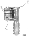
- the base 1 can be connected to the device by means of metal contacts 8 which interconnect directly with the device (which may be a fabric integrating conductive parts integrated or not in the fabric) or through an electrical circuit ( PCB, Flex,...) welded to the base and interfacing with the device ( picture 3 ).
- metal contacts 8 which interconnect directly with the device (which may be a fabric integrating conductive parts integrated or not in the fabric) or through an electrical circuit ( PCB, Flex,%) welded to the base and interfacing with the device ( picture 3 ).
- Plug 2 is made up of electrically conductive parts separated by electrically insulating parts. It can be made up of any type of assembly of parts ensuring the function of signal transmission and electrical insulation ( figure 1 And figure 4 ). Plug 2 and base 1 are preferably “cleanable” in the sense that it is easy to access the surface in order to remove dirt/deposits/particles without a specific cleaning tool.
- Plug 2 is connected and disconnected from base 1 using one hand.
- connection/disconnection can be achieved by simply pressing/pulling plug 2 (variant without locking) ( Figure 5 ).
- the connector comprises a lock and a lateral pressure on both sides (or any other voluntary action) is necessary in order to release the locking mechanism.
- the plug 2 must have a certain elasticity in order to guarantee electrical contact with the base 1.
- each contact 3 can be mounted axially movable independently of the other contacts 3 in order to ensure that each contact 3 is under pressure on the corresponding track 5 of the base 1.
- the contacts 3 pass through a flexible membrane 9, obtained for example by molding a rubber on the contacts 3 or any other means in order to constitute a subassembly allowing the individual mobility of the contacts 3 with respect to each other ( figure 5 ).
- the membrane 9 also makes it possible to guarantee the tightness of the assembly.
- An elastic element (not shown in the illustrations), inducing a return mechanism in the direction of the base 1, makes it possible to exert individual pressure on each contact 3 in order to guarantee electrical continuity on each contact 3 . It should be noted that the membrane 9 can exert this function of elastic element.
- the almost smooth surface of the membrane 9 and the contacts 3 also makes it possible to guarantee perfect “cleanability”, similar to that of the base 1 ( figure 6 ).
- wires of the cable or any other means of connection eg PCB (not shown) are connected (eg welded horizontally) on the rear part of each contact 3 in order to guarantee the electrical connection while limiting the size .
- a cover covers the assembly in order to mechanically protect the system and make it watertight ( figure 7 ).
- the concentric tracks form circular grooves in the face of the base.
- the number of outputs 10 of plug 2 and base 1 can be multiple ( figure 8 )
- Plug 2 can include a "base” part to allow stacking of several plugs/bases ( figure 9 )
- the locking and/or plugging-in receipt of the connector can be achieved by means of a spring ring 11 having a certain elasticity, the ring 11 resting on balls 12 which themselves come to be housed in a groove 13 arranged on the base ( figure 1 And 3 ).
- FIG. 10 A possible illustration of the spring ring 11 is shown in the figure 10 and its integration in sheet 2 is illustrated on the figure 11 .
- the position of the ball seats 14 ( figure 2 ) can be multiple and offer several locking points to prevent rotation once inserted.
Landscapes
- Coupling Device And Connection With Printed Circuit (AREA)
- Details Of Connecting Devices For Male And Female Coupling (AREA)
- Connector Housings Or Holding Contact Members (AREA)
Description
La présente invention concerne les connecteurs, en particulier les connecteurs électriques.The present invention relates to connectors, in particular electrical connectors.
Dans la plupart des cas, l'utilisation d'un connecteur multipolaire nécessite que les deux composants principaux (p.ex. un composant contenant des contacts mâles et un composant avec des contacts femelles) soient fixés l'un par rapport à l'autre selon une orientation angulaire spécifique.In most cases, the use of a multi-pole connector requires that the two main components (e.g. a component containing male contacts and a component with female contacts) are fixed in relation to each other in a specific angular orientation.
Le fait de devoir aligner un composant par rapport à l'autre, préalablement à la connexion, constitue un désagrément.The fact of having to align one component with respect to the other, prior to connection, constitutes an inconvenience.
Il existe donc un besoin de pouvoir supprimer ce désagrément. Le document
L'invention proprement dite consiste en un connecteur, tel que revendiqué dans le revendication 1, comprenant une embase de forme sensiblement cylindrique et une fiche, connectable à l'embase de manière amovible, dans lequel sont disposés une pluralité de contacts. L'embase comporte une face conductrice en forme de disque sur ou dans laquelle est disposée au moins une piste conductrice formant au moins un arc de cercle dont le centre se confond sensiblement avec le centre de la face conductrice, ladite piste étant en outre disposée de manière à autoriser un couplage électrique mécanique avec l'un des dits contacts.The invention proper consists of a connector, as claimed in
Dans le connecteur selon l'invention, l'embase et la fiche constituent les deux composants principaux qui forment le connecteur.In the connector according to the invention, the base and the plug constitute the two main components which form the connector.
Dans la configuration particulière qui ne comporte qu'une seule piste circulaire, le centre de la face de l'embase est un disque conducteur, qui est disposé de manière à autoriser un couplage électrique avec un contact de la fiche disposé au centre de ce dernier.In the particular configuration which comprises only one circular track, the center of the face of the base is a conductive disc, which is arranged in such a way as to allow electrical coupling with a contact of the plug arranged in the center of the latter. .
De préférence le connecteur comporte au moins deux pistes conductrices circulaires qui sont disposées de manière concentrique.Preferably, the connector comprises at least two circular conductive tracks which are arranged concentrically.
Chaque contact de la fiche est monté mobile axialement, de façon indépendante des autres contacts, afin d'assurer un contact mécanique permanent avec les pistes conductrices de l'embase.Each contact of the plug is mounted to move axially, independently of the other contacts, in order to ensure permanent mechanical contact with the conductive tracks of the base.
Un mécanisme est prévu pour exercer une force de rappel sur chaque contact.A mechanism is provided to exert a restoring force on each contact.
Selon l'invention, les contacts sont disposés à travers une membrane souple, p.ex. en caoutchouc, qui est étanche.According to the invention, the contacts are arranged through a flexible membrane, eg made of rubber, which is sealed.
La fiche, dans sa globalité, peut être orientée selon une direction unique. Alternativement elle peut être coudée.The sheet, as a whole, can be oriented in a single direction. Alternatively it can be angled.
La fiche est connectable en rotation libre autour de l'embase, ou selon un nombre limité d'orientations angulaires.The plug can be connected in free rotation around the base, or according to a limited number of angular orientations.
L'invention sera mieux comprise dans la description ci-dessous qui contient notamment quelques exemples illustrés.The invention will be better understood in the description below which contains in particular a few illustrated examples.
-
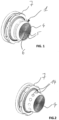
La
figure 1 représente une variante de l'invention avec une embase conçue pour une orientation libre de la fiche.Therefigure 1 represents a variant of the invention with a base designed for free orientation of the plug. -
La
figure 2 représente une autre variante de l'invention avec une embase conçue pour des orientations angulaires limitées de la fiche.Therefigure 2 represents another variant of the invention with a base designed for limited angular orientations of the plug. -
La
figure 3 représente une vue latérale de l'embase.Therepicture 3 shows a side view of the base. -
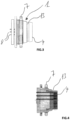
La
figure 4 représente une vue en coupe d'une embase.Therefigure 4 shows a sectional view of a base. -
La
figure 5 représente un couple fiche (coudée)-embase connectésTherefigure 5 represents a connected (elbow) plug-receptacle couple -
La
figure 6 représente une autre vue d'une fiche coudée.Therefigure 6 shows another view of an angled plug. -
La
figure 7 montre le câblage d'une fiche.Therefigure 7 shows the wiring of a plug. -
La
figure 8 représente une fiche comprenant plusieurs sorties.Therefigure 8 represents a form with several outputs. -
La
figure 9 représente un empilement de fiches/embases.Therefigure 9 represents a stack of plugs/bases. -
La
figure 10 représente une bague ressort.Therefigure 10 represents a ring spring. -
La
figure 11 représente l'intégration d'une bague ressort dans une fiche.Therefigure 11 represents the integration of a spring ring in a plug.
- 1. Embase1. Base
- 2. Fiche2. Sheet
- 3. Contact3.Contact
- 4. Face conductrice4. Conductive face
- 5. Piste conductrice5. Conductor track
- 6. Centre de la face conductrice6. Center of conductive face
- 7. Ecrou7. Nut
- 8. Contact8.Contact
- 9. Membrane9. Diaphragm
- 10.Sortie10.Exit
- 11. Bague ressort11. Spring ring
- 12. Bille12. Ball
- 13.Gorge circulaire13.Circular groove
- 14. Logement de bille14. Ball seat
Selon le mode de réalisation illustré dans le présent document, le connecteur comporte 7 contacts.According to the embodiment illustrated in this document, the connector has 7 contacts.
Il va de soi que l'invention ne se limite pas à cette configuration. Elle couvre également tous les connecteurs comportant au moins deux contacts.It goes without saying that the invention is not limited to this configuration. It also covers all connectors with at least two contacts.
De même, les dimensions du connecteur selon l'invention peuvent être quelconques.Similarly, the dimensions of the connector according to the invention can be arbitrary.
Le connecteur selon l'invention a la particularité de ne pas nécessiter d'orientation préalable de la fiche 2 (p.ex. un élément câblé) par rapport à l'embase 1 (p.ex. un élément de boîtier d'appareil). Cet avantage résulte de la géométrie cylindrique/circulaire de l'embase et de sa face conductrice 4 (voir p.ex. la
Une orientation peut néanmoins être donnée et limiter les possibilités d'enfichage à un nombre fini de positions angulaires différentes (p.ex quatre positions séparées de 90° ou 12 positions séparées de 30°) comme décrit sur la
L'embase 1 est constituée d'un corps pouvant être fixé sur un dispositif externe par l'intermédiaire d'un élément de fixation tel qu'un écrou 7 (
L'embase 1 peut se connecter au dispositif par l'intermédiaire de contacts métalliques 8 qui s'interconnectent directement avec le dispositif (pouvant être un tissu intégrant des partie conductrices intégrées ou non dans le tissu) ou au travers d'un circuit électrique (PCB, Flex,...) soudé à l'embase et s'interfaçant avec le dispositif (
La fiche 2 est composée de parties électriquement conductrices séparées par des parties électriquement isolantes. Il peut être constitué de tout type d'assemblage de pièces permettant d'assurer la fonction de transmission de signal et d'isolation électrique (
Avantageusement la fiche 2 se connecte et se déconnecte de l'embase 1 à l'aide d'une seule main.
La connexion/déconnexion peut être réalisée par simple pression/traction sur la fiche 2 (variante sans verrouillage) (
De préférence la fiche 2 doit présenter une certaine élasticité afin de garantir le contact électrique avec l'embase 1. A cet effet, chaque contact 3 peut être monté mobile axialement de façon indépendante des autres contacts 3 afin de garantir que chaque contact 3 soit en pression sur la piste 5 correspondante de l'embase 1. Preferably, the
Avantageusement les contacts 3 traversent une membrane souple 9, obtenue p.ex par surmoulage d'un caoutchouc sur les contacts 3 ou tout autre moyen afin de constituer un sous-ensemble permettant la mobilité individuelle des contacts 3 les uns par rapport aux autres (
La membrane 9 permet également de garantir l'étanchéité de l'ensemble.The membrane 9 also makes it possible to guarantee the tightness of the assembly.
Un élément élastique (non représenté sur les illustrations), induisant un mécanisme de rappel en direction de l'embase 1, permet d'exercer une pression individuelle sur chaque contact 3 afin de garantir la continuité électrique sur chaque contact 3 . A relever que la membrane 9 peut exercer cette fonction d'élément élastique.An elastic element (not shown in the illustrations), inducing a return mechanism in the direction of the
La surface quasi lisse de la membrane 9 et des contacts 3 permet de garantir également une parfaite « nettoyabilité » , similaire à celle de l'embase 1 (
Les fils du câble ou tout autre moyen de liaison, p.ex PCB (non-illustré), sont connectés (p.ex soudés horizontalement) sur la partie arrière de chaque contact 3 afin de garantir la liaison électrique tout en limitant l'encombrement. Un capot recouvre l'ensemble afin de protéger mécaniquement le système et le rendre étanche (
Selon une autre variante (non-illustrée) de l'invention les pistes concentriques forment des gorges circulaires dans la face de l'embase.According to another variant (not shown) of the invention, the concentric tracks form circular grooves in the face of the base.
Le nombre de sorties 10 de la fiche 2 et de l'embase 1 peut être multiple (
La fiche 2 peut inclure une partie « embase » afin de permettre un empilement de plusieurs fiches/embases (
Le verrouillage ou/et la quittance d'enfichage du connecteur peuvent être réalisés au moyen d'une bague ressort 11 présentant une certaine élasticité, la bague 11 s'appuyant sur des billes 12 qui viennent elles-mêmes se loger dans une gorge 13 aménagée sur l'embase (
Une illustration possible de la bague ressort 11 est illustrée sur la
La position des logements de bille 14 (
Claims (6)
- Connector comprising a socket (1) of substantially cylindrical form and a plug (2), that can be removably connected to the socket, in which there are arranged a plurality of contacts (3); the socket (1) comprising a conductive face (4) on or in which there is arranged at least one conductive track (5) forming at least one circular arc whose centre (6) substantially coincides with the centre of the conductive face (4); said track (5) being also arranged so as to allow a mechanical electrical coupling with one of said contacts (3), connector in which each contact (3) is mounted to be axially mobile, independently of the other contacts, the contacts being arranged through a flexible membrane, said membrane being seal-tight, the connector comprising a mechanism comprising an elastic element exerting a return force on each contact towards the socket (1) and making it possible to exert an individual pressure on each contact (3), said elastic element being formed by the membrane (9), the connector being characterized in that the plug (2) comprises a spring ring (11) pressing on balls (12) which are housed in a groove of the socket (1) such that the plug (2) can be connected so as to rotate freely around the socket (1) or in ball housings (14) forming locking points such that the plug (2) can be connected according to a limited number of orientations around the socket (1).
- Connector according to Claim 1, comprising at least two circular conductive tracks (5) arranged concentrically.
- Connector according to either one of the preceding claims, wherein the plug (2) is bent.
- Connector according to any one of the preceding claims, wherein the contacts (3) are distributed asymmetrically on the surface of the conductive face (4).
- Connector according to one of the preceding claims, wherein the plug comprises a part in the form of a socket allowing a stacking of several plugs/sockets.
- Connector according to one of the preceding claims, wherein the socket is intended to be fixed to an external device by a fixing element and is intended to be connected to the device by contacts (8) interconnecting directly with the device or through an electrical circuit welded to the socket and intended to be interfaced with the device.
Applications Claiming Priority (3)
| Application Number | Priority Date | Filing Date | Title |
|---|---|---|---|
| IB2015058257 | 2015-10-27 | ||
| IB2016052275 | 2016-04-21 | ||
| PCT/IB2016/056139 WO2017072620A1 (en) | 2015-10-27 | 2016-10-13 | Multipolar connector |
Publications (3)
| Publication Number | Publication Date |
|---|---|
| EP3369145A1 EP3369145A1 (en) | 2018-09-05 |
| EP3369145C0 EP3369145C0 (en) | 2023-08-30 |
| EP3369145B1 true EP3369145B1 (en) | 2023-08-30 |
Family
ID=57354408
Family Applications (1)
| Application Number | Title | Priority Date | Filing Date |
|---|---|---|---|
| EP16798557.1A Active EP3369145B1 (en) | 2015-10-27 | 2016-10-13 | Multipolar connector |
Country Status (15)
| Country | Link |
|---|---|
| US (1) | US10574006B2 (en) |
| EP (1) | EP3369145B1 (en) |
| JP (1) | JP6827042B2 (en) |
| KR (1) | KR20180070614A (en) |
| CN (1) | CN108352665A (en) |
| AU (1) | AU2016347360B2 (en) |
| BR (1) | BR112018007944A2 (en) |
| CA (1) | CA3002127A1 (en) |
| IL (1) | IL258911B (en) |
| MX (1) | MX2018005311A (en) |
| MY (1) | MY189603A (en) |
| RU (1) | RU2719347C2 (en) |
| SG (1) | SG11201803171RA (en) |
| TN (1) | TN2018000117A1 (en) |
| WO (1) | WO2017072620A1 (en) |
Families Citing this family (13)
| Publication number | Priority date | Publication date | Assignee | Title |
|---|---|---|---|---|
| WO2019193567A1 (en) | 2018-04-06 | 2019-10-10 | Fischer Connectors Holding S.A. | Multipolar connector |
| US11374351B2 (en) * | 2018-04-06 | 2022-06-28 | Fischer Connectors Holding S.A. | Multipolar connector |
| RU2755722C1 (en) * | 2019-01-09 | 2021-09-20 | общество с ограниченной ответственностью "ЗЭТО-Газовые Технологии" | Single-pole high-current connector |
| US11547169B2 (en) | 2019-01-25 | 2023-01-10 | Stryker Corporation | Surgical apparel system |
| JP2022543071A (en) | 2019-07-31 | 2022-10-07 | ストライカー・コーポレイション | Personal protective system including shielded medical gown |
| EP3789235A1 (en) | 2019-09-06 | 2021-03-10 | ODU GmbH & Co KG. | Plug-in connector with a locking mechanism |
| DE102019125784B4 (en) * | 2019-09-25 | 2021-02-11 | Audi Ag | Charging socket for an energy supply arrangement, corresponding energy supply arrangement and method for operating a charging socket |
| US20230035797A1 (en) | 2019-12-18 | 2023-02-02 | Conextivity Group Sa | Connector Comprising An Optical Interface |
| WO2021186302A1 (en) | 2020-03-16 | 2021-09-23 | Fischer Connectors Holding S.A. | Electrical connection with cable as contact element |
| EP3926761A1 (en) | 2020-06-19 | 2021-12-22 | Fischer Connectors Holding S.A. | Interface for products intended to receive a connector part |
| US11677194B2 (en) * | 2020-10-09 | 2023-06-13 | Te Connectivity Solutions Gmbh | Quick disconnect electrical connector with circular contacts |
| US11437748B2 (en) * | 2020-10-09 | 2022-09-06 | Te Connectivity Solutions Gmbh | Quick disconnect electrical connector with circular contacts |
| US11728601B2 (en) * | 2020-11-05 | 2023-08-15 | ReVert Technologies, Inc. | Modular power source |
Citations (3)
| Publication number | Priority date | Publication date | Assignee | Title |
|---|---|---|---|---|
| WO1997002630A1 (en) * | 1995-07-03 | 1997-01-23 | Quad Erat Demonstrandum Aktiebolag | Coupling device |
| US20090280673A1 (en) * | 2004-12-02 | 2009-11-12 | Ran Kohen | Quick connect assembly |
| US20110098601A1 (en) * | 2009-10-26 | 2011-04-28 | Ky Huynh | Medical device assembly having freedom of rotation |
Family Cites Families (46)
| Publication number | Priority date | Publication date | Assignee | Title |
|---|---|---|---|---|
| US2824290A (en) | 1954-09-23 | 1958-02-18 | Pyle National Co | Multi-contact duplicate engaging connector |
| US2892991A (en) * | 1955-12-29 | 1959-06-30 | Deutsch Co | Electrical connector |
| US3112975A (en) | 1960-10-31 | 1963-12-03 | William W Hamel | Electrical connectors |
| FR1354923A (en) | 1963-01-28 | 1964-03-13 | Socapex | Self-locking electrical connector |
| US3237147A (en) | 1963-11-22 | 1966-02-22 | Honeywell Inc | Electrical apparatus |
| US3521216A (en) | 1968-06-19 | 1970-07-21 | Manuel Jerair Tolegian | Magnetic plug and socket assembly |
| FR2456406A1 (en) * | 1979-05-09 | 1980-12-05 | Const Radiotelephoniques | Two part connector for remote equipment - provides watertight contacts and is isolated when separated |
| US4601528A (en) | 1985-08-20 | 1986-07-22 | Spier Martin I | Hermetic self-locking electrical connector |
| DE3722196A1 (en) * | 1987-07-04 | 1989-01-12 | Friedrich Maier | Electrical coupling for the multipole connection of two cable networks (line networks) |
| JPH0252287U (en) * | 1988-10-07 | 1990-04-16 | ||
| DE8910843U1 (en) | 1989-09-11 | 1991-01-17 | Siemens Ag, 1000 Berlin Und 8000 Muenchen, De | |
| DE4135679C2 (en) | 1991-10-30 | 2001-10-11 | Bosch Gmbh Robert | Plug for electrical connections |
| FR2690569B1 (en) | 1992-04-23 | 1996-06-07 | Souriau & Cie | LOCKABLE ELECTRICAL CONNECTOR OF THE PUSH-PULL TYPE. |
| US5358409A (en) | 1993-08-31 | 1994-10-25 | Cardiometrics, Inc. | Rotary connector for flexible elongate member having electrical properties |
| US5509821A (en) | 1994-11-14 | 1996-04-23 | Itt Corporation | D-sub connector |
| CA2176047C (en) | 1995-05-22 | 2000-04-11 | Mohi Sobhani | Spring loaded rotary connector |
| US5865638A (en) | 1995-12-21 | 1999-02-02 | Alcoa Fujikura Ltd. | Electrical connector |
| US6331117B1 (en) | 1998-06-05 | 2001-12-18 | Gary L. Brundage | Electrical component system with rotatable electrical contacts |
| US6395985B1 (en) | 1999-11-23 | 2002-05-28 | Sapco | Sealed electrical terminal with anti-rotation locking system |
| US6243870B1 (en) | 2000-03-14 | 2001-06-12 | Pod Development, Inc. | Personal computer network infrastructure of an article of clothing |
| US6895261B1 (en) | 2000-07-13 | 2005-05-17 | Thomas R. Palamides | Portable, wireless communication apparatus integrated with garment |
| US6716048B2 (en) | 2001-03-14 | 2004-04-06 | Itt Manufacturing Enterprises, Inc. | Coupling mechanism for electrical connectors |
| US7192303B2 (en) | 2001-05-31 | 2007-03-20 | Ran Kohen | Quick connect device for electrical fixtures |
| EP1642361B1 (en) | 2003-06-30 | 2007-06-06 | Koninklijke Philips Electronics N.V. | A textile interconnect |
| IL159032A0 (en) * | 2003-11-24 | 2004-05-12 | Safety Quick Light Ltd | Swivellable electric socket-plug combination |
| US7151455B2 (en) | 2004-04-30 | 2006-12-19 | Kimberly-Clark Worldwide, Inc. | Activating a data tag by load or orientation or user control |
| AU2005311620A1 (en) | 2004-12-02 | 2006-06-08 | Ran Kohen | Quick connect assembly |
| US7462035B2 (en) | 2005-07-27 | 2008-12-09 | Physical Optics Corporation | Electrical connector configured as a fastening element |
| US7293994B2 (en) * | 2005-12-08 | 2007-11-13 | International Business Machines Corporation | Method and apparatus for electrically connecting two substrates using a resilient wire bundle captured in an aperture of an interposer by a retention member |
| US8142200B2 (en) * | 2007-03-26 | 2012-03-27 | Liposonix, Inc. | Slip ring spacer and method for its use |
| ITPD20080197A1 (en) | 2008-06-30 | 2010-01-01 | Inarca Spa | ELECTRIC CONNECTOR, TWO OR MORE WAYS, SEALED SEASON |
| CN101685936A (en) | 2008-09-25 | 2010-03-31 | 鸿富锦精密工业(深圳)有限公司 | Rotary connection device |
| US8308489B2 (en) | 2008-10-27 | 2012-11-13 | Physical Optics Corporation | Electrical garment and electrical garment and article assemblies |
| DE202009003592U1 (en) | 2009-03-13 | 2009-05-20 | Rosenberger Hochfrequenztechnik Gmbh & Co. Kg | Sealing of a spring-loaded contact pin |
| US8490525B2 (en) | 2009-05-21 | 2013-07-23 | Pct International, Inc. | Coaxial connector torque application device |
| US20110098733A1 (en) | 2009-10-26 | 2011-04-28 | Ky Huynh | Medical device assembly having freedom of rotation |
| FR2968467B1 (en) | 2010-12-01 | 2013-04-12 | Legrand France | POWER SOCKET AND ELECTRICAL PLUG EQUIPPED WITH MEANS OF MAGNETIC ATTRACTION |
| EP2533374A1 (en) | 2011-06-06 | 2012-12-12 | novero GmbH | Connector assembly with a magnetic fixation |
| KR20130039665A (en) * | 2011-10-12 | 2013-04-22 | 정기호 | Adaptor for preventing plug breakaway |
| JP5822735B2 (en) | 2012-01-16 | 2015-11-24 | 株式会社ヨコオ | Spring connector with waterproof function |
| US8961191B2 (en) | 2013-03-15 | 2015-02-24 | Garmin Switzerland Gmbh | Electrical connector for pedal spindle |
| FR3010245B1 (en) * | 2013-08-28 | 2016-10-21 | Oreal | ELECTRICAL ASSEMBLY WITH SEALED CONNECTION |
| US9300083B2 (en) * | 2013-09-30 | 2016-03-29 | Apple Inc. | Stackable magnetically-retained connector interface |
| JP6395327B2 (en) | 2016-03-18 | 2018-09-26 | 株式会社ヨコオ | Spring connector |
| DK3501065T3 (en) | 2016-08-19 | 2024-01-08 | Ppc Broadband Inc | COAXIAL CABLE CONNECTORS WITH GROUND CONTINUITY |
| CN106299871B (en) | 2016-09-30 | 2019-09-06 | 中航光电科技股份有限公司 | A kind of locking ball type connector and its connector shell |
-
2016
- 2016-10-13 KR KR1020187013342A patent/KR20180070614A/en not_active Application Discontinuation
- 2016-10-13 BR BR112018007944-8A patent/BR112018007944A2/en not_active Application Discontinuation
- 2016-10-13 AU AU2016347360A patent/AU2016347360B2/en not_active Ceased
- 2016-10-13 TN TNP/2018/000117A patent/TN2018000117A1/en unknown
- 2016-10-13 CA CA3002127A patent/CA3002127A1/en not_active Abandoned
- 2016-10-13 JP JP2018521591A patent/JP6827042B2/en active Active
- 2016-10-13 EP EP16798557.1A patent/EP3369145B1/en active Active
- 2016-10-13 MY MYPI2018001086A patent/MY189603A/en unknown
- 2016-10-13 MX MX2018005311A patent/MX2018005311A/en unknown
- 2016-10-13 WO PCT/IB2016/056139 patent/WO2017072620A1/en active Application Filing
- 2016-10-13 RU RU2018117864A patent/RU2719347C2/en active
- 2016-10-13 CN CN201680063324.7A patent/CN108352665A/en active Pending
- 2016-10-13 US US15/769,392 patent/US10574006B2/en active Active
- 2016-10-13 SG SG11201803171RA patent/SG11201803171RA/en unknown
-
2018
- 2018-04-24 IL IL258911A patent/IL258911B/en unknown
Patent Citations (3)
| Publication number | Priority date | Publication date | Assignee | Title |
|---|---|---|---|---|
| WO1997002630A1 (en) * | 1995-07-03 | 1997-01-23 | Quad Erat Demonstrandum Aktiebolag | Coupling device |
| US20090280673A1 (en) * | 2004-12-02 | 2009-11-12 | Ran Kohen | Quick connect assembly |
| US20110098601A1 (en) * | 2009-10-26 | 2011-04-28 | Ky Huynh | Medical device assembly having freedom of rotation |
Also Published As
| Publication number | Publication date |
|---|---|
| EP3369145C0 (en) | 2023-08-30 |
| RU2719347C2 (en) | 2020-04-17 |
| WO2017072620A1 (en) | 2017-05-04 |
| US20180323556A1 (en) | 2018-11-08 |
| CA3002127A1 (en) | 2017-05-04 |
| MX2018005311A (en) | 2018-08-14 |
| RU2018117864A (en) | 2019-11-28 |
| IL258911B (en) | 2022-02-01 |
| KR20180070614A (en) | 2018-06-26 |
| US10574006B2 (en) | 2020-02-25 |
| CN108352665A (en) | 2018-07-31 |
| JP2018532242A (en) | 2018-11-01 |
| JP6827042B2 (en) | 2021-02-10 |
| AU2016347360A1 (en) | 2018-05-10 |
| BR112018007944A2 (en) | 2018-10-30 |
| IL258911A (en) | 2018-06-28 |
| RU2018117864A3 (en) | 2019-11-28 |
| MY189603A (en) | 2022-02-19 |
| SG11201803171RA (en) | 2018-05-30 |
| TN2018000117A1 (en) | 2019-10-04 |
| AU2016347360B2 (en) | 2021-04-01 |
| EP3369145A1 (en) | 2018-09-05 |
Similar Documents
| Publication | Publication Date | Title |
|---|---|---|
| EP3369145B1 (en) | Multipolar connector | |
| US9755388B2 (en) | Reconfigurable plug strip | |
| EP2356724B1 (en) | Electric connector, and corresponding electric connection element, electric linking member, and assembling method | |
| FR2475812A1 (en) | ELECTRICAL CONNECTING DEVICE COMPRISING AN IMPROVED MECHANISM OPPOSING THE DISASSEMBLY | |
| FR2635230A1 (en) | ADAPTER FOR USE IN FORMING A TWO-OUTPUT ARMORED ELECTRICAL CONNECTOR | |
| FR2482373A1 (en) | ELECTRICAL CONNECTOR WITH SCREEN AGAINST ELECTROMAGNETIC INTERFERENCE | |
| EP3756248A1 (en) | Multipolar connector | |
| WO2019193567A1 (en) | Multipolar connector | |
| CA2914660A1 (en) | Plug-in connector | |
| EP2572406A1 (en) | Antenna interface for a radio receiver | |
| EP2584657B1 (en) | Polarising system for connector and method for mounting said system on a connector | |
| CA3020357C (en) | Optical connector and contacting element for an optical connector | |
| FR3022701A1 (en) | INSULATING MODULE FOR RECEIVING AN ELECTRICAL CONTACT, A SET OF SIMILAR MODULES, AND CONNECTOR COMPRISING AT LEAST TWO ENSEMBLES | |
| WO2001099234A1 (en) | Elastic electrical contact with axial pressure, comprising adjustable connection terminal | |
| CA2948293C (en) | Cutaneous medical device comprising a main part and including a base and a removable electrode | |
| FR2873237A1 (en) | Connector assembly for e.g. electronics component, has connection units with permanent protective coverings, and free end of contacts one unit opening in cavity, where each covering has conducting inserts with inner sides opening in cavity | |
| FR2535122A1 (en) | Twist-prevention device for an electrical cable. | |
| FR3027166A1 (en) | CIRCUIT BREAKER PANEL | |
| FR3098029A1 (en) | Set of an electrical connector, a coding device for said connector and a partition | |
| FR2653942A1 (en) | CONNECTION SYSTEM FOR ARMORED FLAT CABLE. | |
| EP2120243A1 (en) | Adapter for test plug | |
| FR2812459A1 (en) | Coaxial cable connector plug having end section with flexible material outer and inner contact piece with shaped outer surface. | |
| FR2913821A1 (en) | Electrical connecting device for electrical appliances, has sockets comprising flaps with respective identical arms connected to respective identical bodies, where each flap is moved between rest position and disengage position |
Legal Events
| Date | Code | Title | Description |
|---|---|---|---|
| STAA | Information on the status of an ep patent application or granted ep patent |
Free format text: STATUS: UNKNOWN |
|
| STAA | Information on the status of an ep patent application or granted ep patent |
Free format text: STATUS: THE INTERNATIONAL PUBLICATION HAS BEEN MADE |
|
| PUAI | Public reference made under article 153(3) epc to a published international application that has entered the european phase |
Free format text: ORIGINAL CODE: 0009012 |
|
| STAA | Information on the status of an ep patent application or granted ep patent |
Free format text: STATUS: REQUEST FOR EXAMINATION WAS MADE |
|
| 17P | Request for examination filed |
Effective date: 20180522 |
|
| AK | Designated contracting states |
Kind code of ref document: A1 Designated state(s): AL AT BE BG CH CY CZ DE DK EE ES FI FR GB GR HR HU IE IS IT LI LT LU LV MC MK MT NL NO PL PT RO RS SE SI SK SM TR |
|
| AX | Request for extension of the european patent |
Extension state: BA ME |
|
| DAV | Request for validation of the european patent (deleted) | ||
| DAX | Request for extension of the european patent (deleted) | ||
| STAA | Information on the status of an ep patent application or granted ep patent |
Free format text: STATUS: EXAMINATION IS IN PROGRESS |
|
| 17Q | First examination report despatched |
Effective date: 20190404 |
|
| TPAC | Observations filed by third parties |
Free format text: ORIGINAL CODE: EPIDOSNTIPA |
|
| STAA | Information on the status of an ep patent application or granted ep patent |
Free format text: STATUS: EXAMINATION IS IN PROGRESS |
|
| STAA | Information on the status of an ep patent application or granted ep patent |
Free format text: STATUS: EXAMINATION IS IN PROGRESS |
|
| TPAA | Information related to observations by third parties modified |
Free format text: ORIGINAL CODE: EPIDOSCTIPA |
|
| TPAC | Observations filed by third parties |
Free format text: ORIGINAL CODE: EPIDOSNTIPA |
|
| RAP1 | Party data changed (applicant data changed or rights of an application transferred) |
Owner name: CONEXTIVITY GROUP SA |
|
| REG | Reference to a national code |
Ref country code: DE Ref legal event code: R079 Ref document number: 602016082341 Country of ref document: DE Free format text: PREVIOUS MAIN CLASS: H01R0024380000 Ipc: H01R0013240000 Ref country code: DE Ref legal event code: R079 Free format text: PREVIOUS MAIN CLASS: H01R0024380000 Ipc: H01R0013240000 |
|
| GRAP | Despatch of communication of intention to grant a patent |
Free format text: ORIGINAL CODE: EPIDOSNIGR1 |
|
| STAA | Information on the status of an ep patent application or granted ep patent |
Free format text: STATUS: GRANT OF PATENT IS INTENDED |
|
| RIC1 | Information provided on ipc code assigned before grant |
Ipc: H01R 13/627 20060101ALN20230321BHEP Ipc: H01R 35/04 20060101ALI20230321BHEP Ipc: H01R 13/52 20060101ALI20230321BHEP Ipc: H01R 24/38 20110101ALI20230321BHEP Ipc: H01R 13/24 20060101AFI20230321BHEP |
|
| INTG | Intention to grant announced |
Effective date: 20230414 |
|
| RIC1 | Information provided on ipc code assigned before grant |
Ipc: H01R 13/627 20060101ALN20230331BHEP Ipc: H01R 35/04 20060101ALI20230331BHEP Ipc: H01R 13/52 20060101ALI20230331BHEP Ipc: H01R 24/38 20110101ALI20230331BHEP Ipc: H01R 13/24 20060101AFI20230331BHEP |
|
| GRAS | Grant fee paid |
Free format text: ORIGINAL CODE: EPIDOSNIGR3 |
|
| GRAA | (expected) grant |
Free format text: ORIGINAL CODE: 0009210 |
|
| STAA | Information on the status of an ep patent application or granted ep patent |
Free format text: STATUS: THE PATENT HAS BEEN GRANTED |
|
| AK | Designated contracting states |
Kind code of ref document: B1 Designated state(s): AL AT BE BG CH CY CZ DE DK EE ES FI FR GB GR HR HU IE IS IT LI LT LU LV MC MK MT NL NO PL PT RO RS SE SI SK SM TR |
|
| REG | Reference to a national code |
Ref country code: GB Ref legal event code: FG4D Free format text: NOT ENGLISH |
|
| REG | Reference to a national code |
Ref country code: CH Ref legal event code: EP |
|
| REG | Reference to a national code |
Ref country code: DE Ref legal event code: R096 Ref document number: 602016082341 Country of ref document: DE |
|
| REG | Reference to a national code |
Ref country code: IE Ref legal event code: FG4D Free format text: LANGUAGE OF EP DOCUMENT: FRENCH |
|
| U01 | Request for unitary effect filed |
Effective date: 20230918 |
|
| U07 | Unitary effect registered |
Designated state(s): AT BE BG DE DK EE FI FR IT LT LU LV MT NL PT SE SI Effective date: 20230922 |
|
| U20 | Renewal fee paid [unitary effect] |
Year of fee payment: 8 Effective date: 20231123 |
|
| PG25 | Lapsed in a contracting state [announced via postgrant information from national office to epo] |
Ref country code: GR Free format text: LAPSE BECAUSE OF FAILURE TO SUBMIT A TRANSLATION OF THE DESCRIPTION OR TO PAY THE FEE WITHIN THE PRESCRIBED TIME-LIMIT Effective date: 20231201 |
|
| PGFP | Annual fee paid to national office [announced via postgrant information from national office to epo] |
Ref country code: GB Payment date: 20231020 Year of fee payment: 8 |
|
| PG25 | Lapsed in a contracting state [announced via postgrant information from national office to epo] |
Ref country code: IS Free format text: LAPSE BECAUSE OF FAILURE TO SUBMIT A TRANSLATION OF THE DESCRIPTION OR TO PAY THE FEE WITHIN THE PRESCRIBED TIME-LIMIT Effective date: 20231230 |
|
| PG25 | Lapsed in a contracting state [announced via postgrant information from national office to epo] |
Ref country code: RS Free format text: LAPSE BECAUSE OF FAILURE TO SUBMIT A TRANSLATION OF THE DESCRIPTION OR TO PAY THE FEE WITHIN THE PRESCRIBED TIME-LIMIT Effective date: 20230830 Ref country code: NO Free format text: LAPSE BECAUSE OF FAILURE TO SUBMIT A TRANSLATION OF THE DESCRIPTION OR TO PAY THE FEE WITHIN THE PRESCRIBED TIME-LIMIT Effective date: 20231130 Ref country code: IS Free format text: LAPSE BECAUSE OF FAILURE TO SUBMIT A TRANSLATION OF THE DESCRIPTION OR TO PAY THE FEE WITHIN THE PRESCRIBED TIME-LIMIT Effective date: 20231230 Ref country code: HR Free format text: LAPSE BECAUSE OF FAILURE TO SUBMIT A TRANSLATION OF THE DESCRIPTION OR TO PAY THE FEE WITHIN THE PRESCRIBED TIME-LIMIT Effective date: 20230830 Ref country code: GR Free format text: LAPSE BECAUSE OF FAILURE TO SUBMIT A TRANSLATION OF THE DESCRIPTION OR TO PAY THE FEE WITHIN THE PRESCRIBED TIME-LIMIT Effective date: 20231201 |
|
| PGFP | Annual fee paid to national office [announced via postgrant information from national office to epo] |
Ref country code: TR Payment date: 20231117 Year of fee payment: 8 Ref country code: CH Payment date: 20231102 Year of fee payment: 8 |
|
| PG25 | Lapsed in a contracting state [announced via postgrant information from national office to epo] |
Ref country code: PL Free format text: LAPSE BECAUSE OF FAILURE TO SUBMIT A TRANSLATION OF THE DESCRIPTION OR TO PAY THE FEE WITHIN THE PRESCRIBED TIME-LIMIT Effective date: 20230830 |
|
| PG25 | Lapsed in a contracting state [announced via postgrant information from national office to epo] |
Ref country code: ES Free format text: LAPSE BECAUSE OF FAILURE TO SUBMIT A TRANSLATION OF THE DESCRIPTION OR TO PAY THE FEE WITHIN THE PRESCRIBED TIME-LIMIT Effective date: 20230830 |
|
| PG25 | Lapsed in a contracting state [announced via postgrant information from national office to epo] |
Ref country code: SM Free format text: LAPSE BECAUSE OF FAILURE TO SUBMIT A TRANSLATION OF THE DESCRIPTION OR TO PAY THE FEE WITHIN THE PRESCRIBED TIME-LIMIT Effective date: 20230830 Ref country code: RO Free format text: LAPSE BECAUSE OF FAILURE TO SUBMIT A TRANSLATION OF THE DESCRIPTION OR TO PAY THE FEE WITHIN THE PRESCRIBED TIME-LIMIT Effective date: 20230830 Ref country code: ES Free format text: LAPSE BECAUSE OF FAILURE TO SUBMIT A TRANSLATION OF THE DESCRIPTION OR TO PAY THE FEE WITHIN THE PRESCRIBED TIME-LIMIT Effective date: 20230830 Ref country code: CZ Free format text: LAPSE BECAUSE OF FAILURE TO SUBMIT A TRANSLATION OF THE DESCRIPTION OR TO PAY THE FEE WITHIN THE PRESCRIBED TIME-LIMIT Effective date: 20230830 Ref country code: SK Free format text: LAPSE BECAUSE OF FAILURE TO SUBMIT A TRANSLATION OF THE DESCRIPTION OR TO PAY THE FEE WITHIN THE PRESCRIBED TIME-LIMIT Effective date: 20230830 |