EP3368147B1 - Electrical substance clearance from the brain - Google Patents
Electrical substance clearance from the brain Download PDFInfo
- Publication number
- EP3368147B1 EP3368147B1 EP16795440.3A EP16795440A EP3368147B1 EP 3368147 B1 EP3368147 B1 EP 3368147B1 EP 16795440 A EP16795440 A EP 16795440A EP 3368147 B1 EP3368147 B1 EP 3368147B1
- Authority
- EP
- European Patent Office
- Prior art keywords
- csf
- electrode
- electrodes
- control circuitry
- brain
- Prior art date
- Legal status (The legal status is an assumption and is not a legal conclusion. Google has not performed a legal analysis and makes no representation as to the accuracy of the status listed.)
- Active
Links
- 210000004556 brain Anatomy 0.000 title claims description 74
- 239000000126 substance Substances 0.000 title claims description 63
- 210000001175 cerebrospinal fluid Anatomy 0.000 claims description 147
- 210000000798 superior sagittal sinus Anatomy 0.000 claims description 50
- 210000004289 cerebral ventricle Anatomy 0.000 claims description 32
- 210000003625 skull Anatomy 0.000 claims description 31
- 210000002330 subarachnoid space Anatomy 0.000 claims description 31
- 108010090849 Amyloid beta-Peptides Proteins 0.000 claims description 29
- 102000013455 Amyloid beta-Peptides Human genes 0.000 claims description 29
- 108010026424 tau Proteins Proteins 0.000 claims description 8
- 102000013498 tau Proteins Human genes 0.000 claims description 8
- 208000037265 diseases, disorders, signs and symptoms Diseases 0.000 claims description 7
- 201000010099 disease Diseases 0.000 claims description 6
- 230000002964 excitative effect Effects 0.000 claims description 2
- 230000002861 ventricular Effects 0.000 claims 1
- 238000000034 method Methods 0.000 description 16
- 210000003128 head Anatomy 0.000 description 15
- 208000005145 Cerebral amyloid angiopathy Diseases 0.000 description 12
- 239000012530 fluid Substances 0.000 description 12
- 208000024827 Alzheimer disease Diseases 0.000 description 11
- 210000003140 lateral ventricle Anatomy 0.000 description 9
- 238000002474 experimental method Methods 0.000 description 8
- 210000001519 tissue Anatomy 0.000 description 7
- 239000000975 dye Substances 0.000 description 6
- 238000002513 implantation Methods 0.000 description 6
- 229910002835 Pt–Ir Inorganic materials 0.000 description 5
- 239000001045 blue dye Substances 0.000 description 5
- 238000012404 In vitro experiment Methods 0.000 description 4
- 241001465754 Metazoa Species 0.000 description 4
- 238000004891 communication Methods 0.000 description 4
- 230000005684 electric field Effects 0.000 description 4
- 238000005868 electrolysis reaction Methods 0.000 description 4
- 239000000243 solution Substances 0.000 description 4
- 230000000638 stimulation Effects 0.000 description 4
- 230000003213 activating effect Effects 0.000 description 3
- 210000005013 brain tissue Anatomy 0.000 description 3
- 230000001419 dependent effect Effects 0.000 description 3
- 238000011161 development Methods 0.000 description 3
- 238000006073 displacement reaction Methods 0.000 description 3
- 210000001951 dura mater Anatomy 0.000 description 3
- 230000000694 effects Effects 0.000 description 3
- 230000006870 function Effects 0.000 description 3
- 210000000211 third ventricle Anatomy 0.000 description 3
- 241000699666 Mus <mouse, genus> Species 0.000 description 2
- 210000000576 arachnoid Anatomy 0.000 description 2
- 210000003855 cell nucleus Anatomy 0.000 description 2
- 238000009792 diffusion process Methods 0.000 description 2
- 239000012895 dilution Substances 0.000 description 2
- 238000010790 dilution Methods 0.000 description 2
- LOKCTEFSRHRXRJ-UHFFFAOYSA-I dipotassium trisodium dihydrogen phosphate hydrogen phosphate dichloride Chemical compound P(=O)(O)(O)[O-].[K+].P(=O)(O)([O-])[O-].[Na+].[Na+].[Cl-].[K+].[Cl-].[Na+] LOKCTEFSRHRXRJ-UHFFFAOYSA-I 0.000 description 2
- 238000010292 electrical insulation Methods 0.000 description 2
- 210000003722 extracellular fluid Anatomy 0.000 description 2
- 210000001723 extracellular space Anatomy 0.000 description 2
- 210000001061 forehead Anatomy 0.000 description 2
- 238000002347 injection Methods 0.000 description 2
- 239000007924 injection Substances 0.000 description 2
- 229910021645 metal ion Inorganic materials 0.000 description 2
- 239000002953 phosphate buffered saline Substances 0.000 description 2
- 230000005641 tunneling Effects 0.000 description 2
- 239000002699 waste material Substances 0.000 description 2
- 210000004885 white matter Anatomy 0.000 description 2
- 208000037259 Amyloid Plaque Diseases 0.000 description 1
- 208000000094 Chronic Pain Diseases 0.000 description 1
- 208000006561 Cluster Headache Diseases 0.000 description 1
- 238000000116 DAPI staining Methods 0.000 description 1
- 206010012289 Dementia Diseases 0.000 description 1
- 208000031124 Dementia Alzheimer type Diseases 0.000 description 1
- 208000012661 Dyskinesia Diseases 0.000 description 1
- 201000004311 Gilles de la Tourette syndrome Diseases 0.000 description 1
- 208000015592 Involuntary movements Diseases 0.000 description 1
- 241000699670 Mus sp. Species 0.000 description 1
- 238000012879 PET imaging Methods 0.000 description 1
- 208000002193 Pain Diseases 0.000 description 1
- 208000018737 Parkinson disease Diseases 0.000 description 1
- 206010062519 Poor quality sleep Diseases 0.000 description 1
- 238000000692 Student's t-test Methods 0.000 description 1
- 208000000323 Tourette Syndrome Diseases 0.000 description 1
- 208000016620 Tourette disease Diseases 0.000 description 1
- 206010044565 Tremor Diseases 0.000 description 1
- 230000002159 abnormal effect Effects 0.000 description 1
- 238000009825 accumulation Methods 0.000 description 1
- 230000036982 action potential Effects 0.000 description 1
- 230000004913 activation Effects 0.000 description 1
- 150000001413 amino acids Chemical class 0.000 description 1
- 108010064539 amyloid beta-protein (1-42) Proteins 0.000 description 1
- 238000004458 analytical method Methods 0.000 description 1
- 125000000129 anionic group Chemical group 0.000 description 1
- 230000008901 benefit Effects 0.000 description 1
- 238000009534 blood test Methods 0.000 description 1
- 210000003037 cerebral aqueduct Anatomy 0.000 description 1
- 230000001684 chronic effect Effects 0.000 description 1
- 238000010217 densitometric analysis Methods 0.000 description 1
- 238000001514 detection method Methods 0.000 description 1
- 239000003599 detergent Substances 0.000 description 1
- 230000007646 directional migration Effects 0.000 description 1
- 208000035475 disorder Diseases 0.000 description 1
- 239000006185 dispersion Substances 0.000 description 1
- 239000003792 electrolyte Substances 0.000 description 1
- 238000005370 electroosmosis Methods 0.000 description 1
- 206010015037 epilepsy Diseases 0.000 description 1
- 238000000799 fluorescence microscopy Methods 0.000 description 1
- 210000004055 fourth ventricle Anatomy 0.000 description 1
- 238000002599 functional magnetic resonance imaging Methods 0.000 description 1
- 210000004884 grey matter Anatomy 0.000 description 1
- 208000003906 hydrocephalus Diseases 0.000 description 1
- 238000003384 imaging method Methods 0.000 description 1
- 230000001939 inductive effect Effects 0.000 description 1
- 210000005240 left ventricle Anatomy 0.000 description 1
- 238000009593 lumbar puncture Methods 0.000 description 1
- 238000002595 magnetic resonance imaging Methods 0.000 description 1
- 208000024714 major depressive disease Diseases 0.000 description 1
- 238000005259 measurement Methods 0.000 description 1
- 230000005012 migration Effects 0.000 description 1
- 238000013508 migration Methods 0.000 description 1
- 230000003278 mimic effect Effects 0.000 description 1
- 230000017311 musculoskeletal movement, spinal reflex action Effects 0.000 description 1
- 210000000944 nerve tissue Anatomy 0.000 description 1
- 230000001537 neural effect Effects 0.000 description 1
- 230000004770 neurodegeneration Effects 0.000 description 1
- 208000015122 neurodegenerative disease Diseases 0.000 description 1
- 230000009871 nonspecific binding Effects 0.000 description 1
- 238000001543 one-way ANOVA Methods 0.000 description 1
- 230000001151 other effect Effects 0.000 description 1
- 239000002245 particle Substances 0.000 description 1
- 238000013105 post hoc analysis Methods 0.000 description 1
- 230000002265 prevention Effects 0.000 description 1
- 230000004044 response Effects 0.000 description 1
- 210000005241 right ventricle Anatomy 0.000 description 1
- 230000035807 sensation Effects 0.000 description 1
- 210000000278 spinal cord Anatomy 0.000 description 1
- 238000001356 surgical procedure Methods 0.000 description 1
- 238000012353 t test Methods 0.000 description 1
Images


Classifications
-
- A—HUMAN NECESSITIES
- A61—MEDICAL OR VETERINARY SCIENCE; HYGIENE
- A61N—ELECTROTHERAPY; MAGNETOTHERAPY; RADIATION THERAPY; ULTRASOUND THERAPY
- A61N1/00—Electrotherapy; Circuits therefor
- A61N1/18—Applying electric currents by contact electrodes
- A61N1/32—Applying electric currents by contact electrodes alternating or intermittent currents
- A61N1/36—Applying electric currents by contact electrodes alternating or intermittent currents for stimulation
- A61N1/3605—Implantable neurostimulators for stimulating central or peripheral nerve system
- A61N1/3606—Implantable neurostimulators for stimulating central or peripheral nerve system adapted for a particular treatment
- A61N1/36082—Cognitive or psychiatric applications, e.g. dementia or Alzheimer's disease
-
- A—HUMAN NECESSITIES
- A61—MEDICAL OR VETERINARY SCIENCE; HYGIENE
- A61N—ELECTROTHERAPY; MAGNETOTHERAPY; RADIATION THERAPY; ULTRASOUND THERAPY
- A61N1/00—Electrotherapy; Circuits therefor
- A61N1/02—Details
- A61N1/04—Electrodes
- A61N1/05—Electrodes for implantation or insertion into the body, e.g. heart electrode
- A61N1/0526—Head electrodes
- A61N1/0529—Electrodes for brain stimulation
-
- A—HUMAN NECESSITIES
- A61—MEDICAL OR VETERINARY SCIENCE; HYGIENE
- A61N—ELECTROTHERAPY; MAGNETOTHERAPY; RADIATION THERAPY; ULTRASOUND THERAPY
- A61N1/00—Electrotherapy; Circuits therefor
- A61N1/18—Applying electric currents by contact electrodes
- A61N1/32—Applying electric currents by contact electrodes alternating or intermittent currents
- A61N1/327—Applying electric currents by contact electrodes alternating or intermittent currents for enhancing the absorption properties of tissue, e.g. by electroporation
-
- A—HUMAN NECESSITIES
- A61—MEDICAL OR VETERINARY SCIENCE; HYGIENE
- A61N—ELECTROTHERAPY; MAGNETOTHERAPY; RADIATION THERAPY; ULTRASOUND THERAPY
- A61N1/00—Electrotherapy; Circuits therefor
- A61N1/02—Details
- A61N1/04—Electrodes
- A61N1/05—Electrodes for implantation or insertion into the body, e.g. heart electrode
- A61N1/0504—Subcutaneous electrodes
-
- A—HUMAN NECESSITIES
- A61—MEDICAL OR VETERINARY SCIENCE; HYGIENE
- A61N—ELECTROTHERAPY; MAGNETOTHERAPY; RADIATION THERAPY; ULTRASOUND THERAPY
- A61N1/00—Electrotherapy; Circuits therefor
- A61N1/02—Details
- A61N1/04—Electrodes
- A61N1/05—Electrodes for implantation or insertion into the body, e.g. heart electrode
- A61N1/0526—Head electrodes
- A61N1/0529—Electrodes for brain stimulation
- A61N1/0534—Electrodes for deep brain stimulation
-
- A—HUMAN NECESSITIES
- A61—MEDICAL OR VETERINARY SCIENCE; HYGIENE
- A61N—ELECTROTHERAPY; MAGNETOTHERAPY; RADIATION THERAPY; ULTRASOUND THERAPY
- A61N1/00—Electrotherapy; Circuits therefor
- A61N1/18—Applying electric currents by contact electrodes
- A61N1/20—Applying electric currents by contact electrodes continuous direct currents
- A61N1/30—Apparatus for iontophoresis, i.e. transfer of media in ionic state by an electromotoric force into the body, or cataphoresis
- A61N1/303—Constructional details
- A61N1/306—Arrangements where at least part of the apparatus is introduced into the body
Definitions
- the present disclosure relates generally to treatment and prevention of Alzheimer's disease and/or cerebral amyloid angiopathy (CAA), and specifically to electrical techniques for treating, preventing, or slowing the progression of Alzheimer's disease and/or CAA.
- CAA cerebral amyloid angiopathy
- Alzheimer's disease is a chronic neurodegenerative disease that causes dementia. Accumulation of substances such as amyloid beta and/or tau protein in the brain is widely believed to contribute to the development of Alzheimer's disease.
- US Patent Application Publication 2014/0324128 to Gross which is assigned to the assignee of the present application, describes apparatus for driving fluid between first and second anatomical sites of a subject.
- the apparatus comprises (1) a first electrode, configured to be coupled to the first anatomical site of the subject; (2) a second electrode, configured to be coupled to the second anatomical site of the subject; and (3) a control unit, configured to (i) detect a pressure difference between the first and second anatomical sites, and (ii) in response to the detected pressure difference, drive fluid between the first and second anatomical sites by applying a treatment voltage between the first and second electrodes.
- a first electrode configured to be coupled to the first anatomical site of the subject
- a second electrode configured to be coupled to the second anatomical site of the subject
- a control unit configured to (i) detect a pressure difference between the first and second anatomical sites, and (ii) in response to the detected pressure difference, drive fluid between the first and second anatomical sites by applying a treatment voltage between the first and second electrodes.
- the invention provides an apparatus as claimed in claim 1.
- a parenchymal electrode is implanted in parenchyma of the brain, and a cerebrospinal fluid (CSF) electrode is implanted in a CSF-filled space of the brain, e.g., selected from a ventricular system and a subarachnoid space.
- Control circuitry is activated to drive the parenchymal and the CSF electrodes to clear a substance, such as amyloid beta and/or tau protein, from the brain parenchyma into the CSF-filled space of the brain.
- the techniques of the present invention in addition to clearing the substance from the brain parenchyma into the CSF-filled space, clear the substance from the CSF-filled space to a superior sagittal sinus of the brain.
- an apparatus comprising:
- an apparatus comprising:
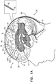
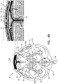
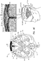
- Figs. 1A-C are schematic illustrations of a system 20 for treating Alzheimer's disease and/or cerebral amyloid angiopathy (CAA), in accordance with respective applications of the present description.
- System 20 comprises parenchymal and cerebrospinal fluid (CSF) electrodes 30 and 32, and control circuitry 34, which is electrically coupled to parenchymal and CSF electrodes 30 and 32, typically by parenchymal and CSF electrode leads 36 and 38, respectively.
- CSF cerebrospinal fluid
- parenchymal electrode 30 is implanted in parenchyma 50 of a brain 52 of a subject identified as at risk of or suffering from Alzheimer's disease and/or from CAA, e.g., using surgical techniques similar to those used for implantation of electrodes for deep brain stimulation.
- parenchymal electrode 30 is implanted elsewhere in the subject in electrical contact with brain parenchyma 50, such as on and in contact with an outer surface of brain 52, as shown for the middle parenchymal electrode 30 illustrated in Fig. 1A .
- CSF electrode 32 is implanted in a CSF-filled space of the brain, such as ventricular system 54 of brain 52 or a subarachnoid space 144 (labeled in Figs. 4A-G ) (e.g., cisterns of subarachnoid space 144).
- CSF electrode 32 may be implanted using techniques known for implanting hydrocephalus shunts, mutatis mutandis.
- ventricular system 54 includes and is limited to lateral ventricles 55 (left and right lateral ventricles 55A and 55B), a third ventricle 56, a fourth ventricle 57, a cerebral aqueduct 59 (labeled in Figs. 4A-G ), interventricular foramina, a median aperture, and left and right lateral apertures.
- Control circuitry 34 is activated to drive parenchymal and CSF electrodes 30 and 32 to clear a substance from brain parenchyma 50 into the CSF-filled space, such as ventricular system 54.
- the substance comprises amyloid beta, metal ions, a tau protein, and/or a waste substance.
- clearing a substance from the brain parenchyma is to be understood as including clearing a portion of the substance, without clearing all of the substance.
- control circuitry 34 applies a voltage or a current between parenchymal and CSF electrodes 30 and 32 (i.e., control circuitry 34 regulates the voltage or the current).
- control circuitry 34 typically comprises appropriate memory, processor(s), and hardware running software that is configured to provide the functionality of control circuitry described herein.
- Current may flow generally through tissue that is located between parenchymal and CSF electrodes 30 and 32.
- at least a portion of the current may flow between (a) parenchymal electrode 30 and (b) an area of the CSF-filled space (e.g., ventricular system 54) nearest parenchymal electrode 30.
- CSF cerebrospinal fluid
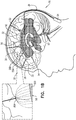
- the inventors have appreciated that because of the low electrical resistance of cerebrospinal fluid (CSF) in the CSF-filled space, such as ventricular system 54, the ventricles are to some extent a single entity electrically. Therefore, a large portion of the current flows to the nearest portion of ventricular system 54, even if CSF electrode 32 is implanted in a ventricle remote from parenchymal electrode 30. For example, as shown in Fig.
- the voltage applied between the electrodes may clear the substance electrophoretically, because of a positive or negative charged interface between the surface of the particles of the substance and the surrounding brain tissue fluids.
- the voltage applied between the electrodes causes a potential difference between brain parenchyma 50 and the CSF-filled space, such as ventricular system 54, which causes movement of the substance from brain parenchyma 50 to the CSF-filled space, such as ventricular system 54.
- the voltage applied between the electrodes may clear the substance electroosmotically, because of a positive or negative charge of fluid in the parenchyma.
- the voltage applied between the electrodes causes a potential difference between brain parenchyma 50 and the CSF-filled space, such as ventricular system 54, which causes increased flow from brain parenchyma 50 to the CSF-filled space, such as ventricular system 54, and thus increased transport of the substance from parenchyma 50 to the CSF-filled space, such as ventricular system 54.
- system 20 comprises a plurality of parenchymal electrodes 30 and/or a plurality of CSF electrodes 32.
- Parenchymal electrodes 30 may be implanted in one or both hemispheres of brain 52, and/or at one or more than one location in each of the hemispheres.
- system 20 comprises a plurality of parenchymal electrodes 30 and exactly one CSF electrode 32.
- the single CSF electrode 32 may be implanted in one of lateral ventricles 55 or third ventricle 56, which, as discussed above, are to a large degree in good electrical connectivity with the other ventricles.
- system 20 comprises (a) exactly two CSF electrodes 32, which are implanted in left and right lateral ventricles 55A and 55B, respectively, or (b) exactly three CSF electrodes 32, which are implanted in left and right lateral ventricles 55A and 55B and third ventricle 56, respectively.
- system 20 typically comprises a corresponding plurality of parenchymal electrode leads 36 and/or a corresponding plurality of CSF electrode leads 38.
- Each of the leads may comprise separate electrical insulation, and/or a portion of the leads may be joined and share common electrical insulation, as shown in Figs. 1A-C for parenchymal electrode leads 36.
- Control circuitry 34 may be activated to independently drive parenchymal electrodes 30, e.g., using separately circuitry. Alternatively, one or more of parenchymal electrodes 30 may be shorted to one another, such that the control circuitry drives the shorted electrodes together. Control circuitry 34 may be activated to drive parenchymal electrodes 30 simultaneously or at different times.
- brain parenchyma 50 in which parenchymal electrode 30 is implanted comprises white matter of the brain.
- treating includes both treating a subject already diagnosed with Alzheimer's disease and/or CAA (such as by delaying, slowing, or reversing progression of the disease, e.g., in a patient diagnosed at an early stage), as well as preventing the development of Alzheimer's disease and/or CAA in a subject not diagnosed with the disease and/or asymptomatic for the disease.
- the techniques described herein may be used to prevent or delay the development of Alzheimer's disease and/or CAA in responsive to detection of an abnormal level of amyloid beta, such as using a blood test or a spinal tap.
- control circuitry 34 is configured to be implanted subcutaneously, such under skin of the skull of the subject if the housing containing the control circuitry is small, or elsewhere in the subject's body, such as in the upper chest, if the housing of the control circuitry is larger (e.g., includes batteries), with leads through the neck, or optionally in the head.
- control circuitry 34 is typically driven by an external controller that is in wireless or wired communication with control circuitry 34.
- the external controller is mounted on a bed of the subject (e.g., disposed within a mattress), and is configured to activate control circuitry 34 only at night, and/or only when the subject is sleeping.
- control circuitry 34 is configured to be disposed externally to the subject.
- control circuitry 34 is activated to drive parenchymal and CSF electrodes 30 and 32 to clear the substance by applying a non-excitatory current between parenchymal and CSF electrodes 30 and 32, i.e., the current does not cause propagation of action potentials.
- control circuitry 34 is activated to set parameters of the current such that the current does not affect, or only minimally affects, neuronal activity.
- the applied current does excite brain tissue, such as to a small extent.
- control circuitry 34 is activated to drive parenchymal and CSF electrodes 30 and 32 to clear the substance by applying direct current (DC) between parenchymal and CSF electrodes 30 and 32.
- DC direct current
- direct current means a current having a constant polarity; the amplitude of the direct current may or may not vary over time, and may sometimes be zero.
- control circuitry 34 is activated to apply the direct current with an average amplitude of at least 1 mA, no more than 5 mA, and/or between 1 and 5 mA. Alternatively or additionally, for some applications, control circuitry 34 is activated to apply the direct current with an average amplitude of less than 1.2 V (such an amplitude may avoid electrolysis in the vicinity of one or both of the electrodes).
- control circuitry 34 is activated to configure parenchymal electrode 30 to be a cathode, and CSF electrode 32 to be an anode.
- control circuitry 34 is activated to configure parenchymal electrode 30 to be an anode, and CSF electrode 32 to be a cathode.
- the selected polarity of the electrodes typically depends on whether the substance has a positive or negative effective charge.
- the selected polarity of the electrodes typically depends on whether the fluid has a positive or negative effective charge.
- control circuitry 34 is activated to apply the direct current as a series of pulses.
- the series of pulses has an average pulse duration of at least 10 milliseconds, no more than 300 seconds, and/or between 10 milliseconds and 300 seconds, such as: (a) at least 10 milliseconds, no more than 100 milliseconds, and/or between 10 and 100 milliseconds, (b) at least 100 milliseconds, no more than 300 seconds (e.g., no more than 500 milliseconds), and/or between 100 and 300 seconds (e.g., between 100 and 500 milliseconds), (c) at least 500 milliseconds, no more than 5 seconds, and/or between 500 milliseconds and 5 seconds, (d) at least 5 seconds, no more than 10 seconds, and/or between 5 and 10 seconds, or (e) at least 10 seconds, no more than 100 seconds, and/or between 10 and 100 seconds.
- the pulses are applied at a frequency of at least 0.001 Hz, no more than 1 kHz, and/or between 0.001 and 1 kHz, such as: (a) at least 100 Hz, no more than 1 kHz, and/or between 100 Hz and 1 kHz, (b) at least 20 Hz, no more than 100 Hz, and/or between 20 and 100 Hz, or (c) at least 1 Hz, no more than 10 Hz, and/or between 1 and 10 Hz.
- the series of pulses has a duty cycle of at least 1%, no more than 50%, and/or between 1% and 50%, such as: (a) at least 1%, no more than 5%, and/or between 1% and 5%, (b) at least 5%, no more than 10%, and/or between 5% and 10%, (c) at least 10%, no more than 25%, and/or between 10% and 25%, or (d) at least 25%, no more than 50%, and/or between 25% and 50%.
- the duty cycle is no more than 90%, because a given level of applied voltage produces higher current in the tissue if the capacitance in the tissue is allowed to discharge between pulses.
- control circuitry 34 applies a voltage between parenchymal and CSF electrodes 30 and 32 in a series of DC pulses
- the resulting current decays because of the effects of tissue electrolytes.
- the current may decay by about two-thirds of its initial magnitude within tens of milliseconds after commencement of application of each pulse.
- control circuitry 34 is activated to apply the voltage intermittently, in order to provide time periods between pulses during which the capacitance discharges.
- control circuitry 34 is activated to apply the voltage intermittently with a preprogrammed frequency and/or duty cycle. These parameters may be (a) applicable to all patients or a subgroup of patients, (b) set during a calibration procedure upon implantation of the electrodes, or (c) set based on a geometry of placement of parenchymal and/or CSF electrodes 30 and/or 32. Alternatively, control circuitry 34 is configured to set these parameters in real time by sensing the current resulting from the applied voltage.
- control circuitry 34 is activated to measure the current resulting from the applied voltage during each of the applied pulses, and to terminate each of the applied pulses when the magnitude of the measured current falls below a threshold value.
- the threshold value may be a preprogrammed constant, or may be based on (e.g., a percentage of) the initial current magnitude measured upon commencement of the respective pulse. Control circuitry 34 waits during a discharge period before applying the next pulse.
- control circuitry 34 is activated to apply, between parenchymal and CSF electrodes 30 and 32, alternating current (AC) in:
- the secondary subset of the pulses does not reverse the clearance of the substance achieved during application of the primary subset of the pulses.
- This technique may also help avoid electrolysis in the vicinity of one or both of the electrodes, even if the primary voltage is higher than a threshold DC voltage (e.g., 1.2 V) that might otherwise cause electrolysis.
- a threshold DC voltage e.g., 1.2 V
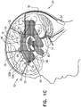
- parenchymal and CSF electrodes 30 and 32 are implanted such that one or more areas of build-up 64 of the substance in brain parenchyma 50 is between the electrodes, rather than implanting parenchymal electrode 30 within the area of build-up.
- the area(s) of build-up may include amyloid plaque and/or tau protein-related nerve tissue tangles.
- the area of build-up is first identified, for example by performing imaging of brain 52, such as MRI (e.g., functional MRI (fMRI)) or PET imaging of brain 52.
- MRI e.g., functional MRI (fMRI)
- PET imaging of brain 52 e.g., PET imaging of brain 52.
- a plurality of parenchymal electrodes 30 and/or a plurality of CSF electrodes 32 may be implanted, such as if there is more than one area of build-up 64 of the substance.
- the one or more parenchymal electrode are implanted such that the one or more areas of build-up 64 are between parenchymal electrode 30A and respective areas 80 of the CSF-filled space, such as ventricular system 54, nearest areas of build-up 64.
- CSF electrode 32 may or may not be implanted near areas 80.
- the substance of area of build-up 64 may still be driven into nearest areas 80 of the CSF-filled space, such as ventricular system 54, because nearest areas 80 are in fluid communication with CSF electrode 32 via CSF of the CSF-filled space, such as ventricular system 54, as discussed above.
- a plurality of parenchymal electrodes 30 and/or a plurality of CSF electrodes 32 may be implanted, such as if there is more than one area of build-up 64 of the substance, or in general in order to provide good clearance of the substance.
- parenchymal electrode 30 is further used for applying deep brain stimulation, as is known in the art.
- the deep brain stimulation may be applied when the electrodes are not being driven to drive the substance into the CSF-filled space, such as the ventricular system.
- the deep brain stimulation may be applied to reduce tremor and block involuntary movements in patients with motion disorders, such as Parkinson's disease, or to treat epilepsy, cluster headaches, Tourette syndrome, chronic pain, or major depression.
- the implantation location of parenchymal electrode 30 may be selected to be appropriate for the treatment of a particular condition, as well as for clearing the substance.
- control circuitry 34 is activated to drive parenchymal and CSF electrodes 30 and 32 in sessions, each of which has a duration of several seconds or several minutes, or continuously for longer periods (e.g., 30 minutes). For some applications, the electrodes are not driven for a period that is at least an hour.
- control circuitry 34 is activated to drive the electrodes only when the subject is sleeping, such as to take advantage of the widening of extracellular spaces and/or to inhibit any sensations that may be associated with the driving.
- control circuitry 34 may be activated to use one or more of the electrodes as EEG electrodes to detect sleep.
- control circuitry 34 is transmitted from a wireless energy transmitter in a device applied to the head, such as a hat, or from a wireless energy transmitter in, under, or above a mattress, such as described hereinabove.
- control circuitry 34 is activated to drive the electrodes according to a pre-selected schedule, such as a duty cycle, such as for a few hours per day.
- control circuitry 34 may be configured to be controlled and/or powered by an extracorporeal control circuitry, such as a control circuitry comprising a wireless transmitter, disposed in and/or in the vicinity of the subject's bed.
- one or more rest periods during which the control circuitry does not drive the electrodes are provided in the pre-selected schedule.
- CSF electrode 32 may be implanted in one of the following sites, rather than in ventricular system 54:
- an electrode is implanted in superior sagittal sinus 142 (labeled in Figs. 4A-G ).
- parenchymal electrode 30 may be implanted in superior sagittal sinus 142, rather than in brain parenchyma 50 (typically, in these applications, CSF electrode 32 is implanted in ventricular system 54).
- control circuitry 34 is configured to detect a voltage difference between parenchyma 50 and the CSF-filled space, and set a level of the voltage applied between parenchymal and cerebrospinal fluid (CSF) electrodes 30 and 32 responsively to the detected voltage difference.
- CSF cerebrospinal fluid
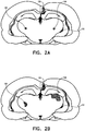
- FIGs. 2A-B are schematic illustrations of cross-sections of a rat brain showing results of an animal experiment performed in accordance with an application of the present invention.
- a rat was anesthetized, a first electrode 130 (a piece of Pt-Ir wire soldered to a miniature connector) was inserted through a hole into the sagittal sinus, and a second electrode 132 (a pieces of Pt-Ir wire soldered to a small electronic connector) was inserted through a hole in dura mater into the right lateral ventricle.
- bromephenol blue dye was stereotaxically delivered into both hemispheres of the rat brain at designated coordinates 120 and 122.
- this experimental setup allowed pairwise comparisons within the same animal, thereby ruling out any other effects that might effect a directed migration of the dye in the brain.
- Control circuitry was activated to apply a constant-polarity (DC) current to only the right hemisphere, between first and second electrodes 130 and 132, configuring first electrode 130 as a cathode and second electrode 132 as an anode, because bromephenol blue dye comprises effectively anionic (negatively-charged) molecules.
- the current was applied by repeatedly alternating between two modes: (a) a first mode, in which the current was applied continuously for 5 minutes at a magnitude of 1-2 mA, and (b) a second mode, in which the current was applied in 10-ms-duration pulses, one pulse per second (i.e., a pulse frequency of 1 Hz), at a magnitude of 1-2 mA.
- Fig. 2B shows the displacement of the bromephenol blue dye after application of the current to the right hemisphere.
- the bromephenol blue dye in the left hemisphere experienced minimal dispersion and no directed displacement.
- the applied current moved the bromephenol blue dye toward the lateral ventricle.
- the dye moved with the average velocity of 0.28 +/- 0.006 mm/min, which was more than 14 times greater than the observed diffusion rate in the left hemisphere.
- the linear displacement of the dye profile center was about 1.9 ⁇ 0.08 mm, while the front of the dye profile reached a maximum distance of about 2.81 ⁇ 0.07 mm from the center of the injection point.
- Fig. 3 is a graph showing results of an in vitro experiment performed in accordance with an application of the present invention.
- the experiment assessed the extent to which application of direct current (DC) eliminated amyloid beta peptides from an artificial cerebrospinal fluid (aCSF) solution (comprising phosphate buffered saline (PBS) solution).
- aCSF cerebrospinal fluid
- PBS phosphate buffered saline
- Constant DC currents of three different durations (5, 10, and 15 minutes) were applied from a 1.5 V alkaline battery to the aCSF solution containing the fluorophore-tagged amyloid beta peptides.
- the directionality and overall capability of amyloid beta to undergo electrophoretic movement was assessed by densitometric analysis of fluorescence on each electrode.
- the fluorescence intensity was measured at both electrodes, and the fluorescence intensity was normalized at the positively-charged electrode (anode) with respect to the negatively-charged electrode (cathode) by taking the ratio of fluorescence. Data was averaged from all the measurements and is presented as mean and standard error of mean in Fig. 3 .
- the current application was applied by the repetition of single pulses.
- the following parameters were used: voltage: 70 V; and frequency: 1 Hz.
- the current application protocol was as follows: (a) 15 minutes with a pulse duration of 1 ms; (b) 15 minutes with a pulse duration of 10 ms; and (c) 15 minutes with a pulse duration of 100 ms.
- the frequency was kept constant but the duty cycle was increased.
- amyloid beta movement directionality in the electrical field was conducted by using antibodies directed against 1-16 amino acid strip of 6E10 (Catalog no. SIG-39320) to visualize the traces of amyloid beta peptide movement in the electrical field. Tissue structure and cell nuclei were visualized by DAPI staining. Amyloid beta movement trajectory was evaluated at different magnifications (4x and 10x). Sagittal slices were stained with antibodies against cell nuclei (blue) and amyloid beta (6E10, green), and imaged by fluorescence microscopy.
- Amyloid beta movement was visualized in mouse brains to which the electrical current was applied.
- the electrode inserted into the lateral ventricle was positively charged, and, similarly to the in vitro experiment described hereinabove with reference to Fig. 3 , the applied current was capable of inducing amyloid beta movement.
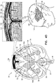
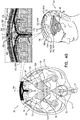
- Figs. 4A-G are schematic illustrations of alternative configurations of system 20, in accordance with respective applications of the present description. These figures show an anterior view of brain 52.
- system 20 is configured to, in addition to clearing the substance (e.g., the amyloid beta, the metal ions, the tau protein, and/or the waste substance) from brain parenchyma 50 into the CSF-filled space, to clear the substance from the CSF-filled space (e.g., subarachnoid space 144) to superior sagittal sinus 142.
- control circuitry 34 is configured to apply the treatment current as direct current.
- control circuitry 34 is configured to simultaneously drive electrodes to both (a) clear the substance from brain parenchyma 50 into the CSF-filled space, and (b) clear the substance from the CSF-filled space to superior sagittal sinus 142.
- control circuitry 34 may be configured to apply different respective voltages to parenchymal electrode 30, CSF electrode 32, and a midplane treatment electrode 150, described below.
- control circuitry 34 may be configured to apply first, second, and third voltages to parenchymal electrode 30, CSF electrode 32, and midplane treatment electrode 150, respectively, the third voltage more positive than the second voltage, which is in turn more positive than first voltage.
- the total potential difference between the first and the third voltages is typically no greater than 1.2 V volt to avoid electrolysis in the vicinity of one or both of the electrodes.
- control circuitry 34 is configured to alternatingly drive sets of the electrodes, such as (a) during a plurality of first time periods, driving parenchymal electrode 30 and CSF electrode 32, in order to clear the substance from brain parenchyma 50 into the CSF-filled space, and (b) during a plurality of second time periods, typically not overlapping with the first time periods, driving midplane treatment electrode 150 and either CSF electrode 32 or another electrode (described below), in order to clear the substance from the CSF-filled space to superior sagittal sinus 142.
- control circuitry 34 is configured to clear the substance to superior sagittal sinus 142 by electroosmotically driving fluid from the CSF-filled space (e.g., subarachnoid space 144) to superior sagittal sinus 142.
- control circuitry 34 is configured to drive the fluid from the CSF-filled space of the brain to superior sagittal sinus 142 by configuring midplane treatment electrode 150 as a cathode, and CSF electrode 32 as an anode.
- control circuitry 34 is configured to clear the substance by electrophoretically driving the substance from the CSF-filled space (e.g., subarachnoid space 144) to superior sagittal sinus 142.
- CSF-filled space e.g., subarachnoid space 14
- application of the treatment current causes a potential difference between the CSF-filled space and superior sagittal sinus 142, which causes movement of the substance from the CSF-filled space to superior sagittal sinus 142.
- parenchymal electrode 30 is implanted in brain parenchyma 50, and CSF electrode 32 is implanted in the CSF-filled space, such as ventricular system 54 or subarachnoid space 144.
- a midplane treatment electrode 150 is disposed either (a) in superior sagittal sinus 142 (as shown in Fig. 4A ), or (b) over superior sagittal sinus 142 (configuration not shown in Fig. 4A , but shown in Figs. 4B-G ).
- a second CSF electrode 152 is implanted the CSF-filled space, such as ventricular system 54 (configuration not shown in Fig.
- Control circuitry 34 is activated to apply (a) a first voltage between parenchymal electrode 30 and CSF electrode 32, to clear the substance from brain parenchyma 50 into the CSF-filled space, and (b) a second voltage between midplane treatment electrode 150 and second CSF electrode 152, to clear the substance from the CSF-filled space to superior sagittal sinus 142.
- This technique may be used in combination with the techniques described hereinbelow with reference to Figs. 4B-G , mutatis mutandis.
- parenchymal electrode 30 is implanted in brain parenchyma 50, and CSF electrode 32 is implanted in the CSF-filled space, such as ventricular system 54 or subarachnoid space 144.
- Midplane treatment electrode 150 is disposed either (a) in superior sagittal sinus 142 (as shown in Fig. 4A ), or (b) over superior sagittal sinus 142 (as shown in Figs. 4B-G ).
- Control circuitry 34 is activated to apply (a) a first voltage between parenchymal electrode 30 and CSF electrode 32, to clear the substance from brain parenchyma 50 into the CSF-filled space, and (b) a second voltage between CSF electrode 32 and midplane treatment electrode 150, to clear the substance from the CSF-filled space to superior sagittal sinus 142.
- midplane treatment electrode 150 is adapted to be disposed over superior sagittal sinus 142.
- midplane treatment electrode 150 is adapted to be disposed under a skull 168 of a head 174 of the subject, such as in contact with an outer surface of superior sagittal sinus 142 (either under the dura mater or in contact with an outer surface of the dura mater).
- midplane treatment electrode 150 is adapted to be disposed outside and in electrical contact with skull 168.
- control circuitry 34 is configured to clear the substance from the CSF-filled space to superior sagittal sinus 142, by applying a treatment current between midplane treatment electrode 150 and CSF electrode 32.
- the placements of midplane treatment electrode 150 shown in Figs. 4B and 4C are used in combination with the configuration described hereinabove with reference to Fig. 4A .
- system 20 comprises a plurality of midplane treatment electrodes 150, such as at least 5, no more than 20, and/or between 5 and 20 midplane treatment electrodes 150.
- Midplane treatment electrodes 150 are disposed either (a) in superior sagittal sinus 142 (configuration not shown in Fig. 4D , but shown in Fig. 4A ), or (b) over superior sagittal sinus 142 (as shown in Fig. 4D , or in Fig. 4B ).
- CSF electrode 32 may be adapted to be disposed between 1 and 12 cm of a sagittal midplane 164 of skull 168.
- the method may comprise implanting CSF electrode 32 between 1 and 12 cm of sagittal midplane 164 of skull 168.
- the CSF-filled space may be subarachnoid space 144
- CSF electrode 32 may be a subarachnoid electrode, configured to be implanted in subarachnoid space 144
- control circuitry 34 may be configured to clear the substance from subarachnoid space 144 to superior sagittal sinus 142.
- system 20 comprises (a) midplane treatment electrodes 150, adapted to be disposed over superior sagittal sinus 142, outside and in electrical contact with skull 168, and (b) lateral treatment electrodes 162, adapted to be disposed at a distance of between 1 and 12 cm of sagittal midplane 164 of skull 168 (the distance is measured in a straight line from a closest portion of each treatment electrode to sagittal midplane 164, rather than along the curvature of skull 168).
- Control circuitry 34 is configured to clear the substance from subarachnoid space 144 to superior sagittal sinus 142, by applying one or more treatment currents between (a) one or more of midplane treatment electrodes 150 and (b) one or more of lateral treatment electrodes 162 (each of the treatment currents is schematically illustrated in the figures by a plurality of current lines 190).
- system 20 comprises as at least 5, no more than 40, and/or between 5 and 40 lateral treatment electrodes 162, such as between 5 and 20 lateral treatment electrodes 162, or between 10 and 40 lateral treatment electrodes.
- the number of each type of treatment electrode is determined based on the size of head 174 of the subject.
- system 20 comprises twice as many lateral treatment electrodes 162 as midplane treatment electrodes 150.
- the one or more treatment currents applied using midplane treatment electrodes 150 and lateral treatment electrodes 162 pass between subarachnoid space 144 and superior sagittal sinus 142, via inferolateral surfaces 170 of superior sagittal sinus 142.
- at least 40%, e.g., at least 75% or at least 90%, of the treatment currents pass between subarachnoid space 144 and superior sagittal sinus 142, via inferolateral surfaces 170 of superior sagittal sinus 142.
- the locations of midplane treatment electrodes 150 and/or lateral treatment electrodes 162 are typically selected such that the one or more treatment currents pass through inferolateral surfaces 170.
- lateral treatment electrodes 162 may be disposed at a distance of least 4 cm, no more than 12 cm, and/or between 4 and 12 cm of sagittal midplane 164 of skull 168; for configurations in which lateral treatment electrodes 162 are implanted under an arachnoid mater 172 of the subject, such as described with reference to Figs. 4C-G , lateral treatment electrodes 162 may be disposed at least 1 cm, no more than 3 cm, and/or between 1 and 3 cm of sagittal midplane 164 of skull 168.
- At least five midplane treatment electrodes 150 are disposed over superior sagittal sinus 142.
- at least five lateral treatment electrodes 162 between 1 and 12 cm of sagittal midplane 164 of skull 168.
- each of lateral treatment electrodes 162 is disposed between 1 and 12 cm of at least one of midplane treatment electrodes 150.
- midplane treatment electrodes 150 are disposed within 10 mm of sagittal midplane 164 of skull 168. Alternatively or additionally, for some applications, midplane treatment electrodes 150 are disposed such that at least one of midplane treatment electrodes 150 is at least 5 mm from another one of midplane treatment electrodes 150, no more than 20 mm from another one of midplane treatment electrodes 150, and/or between 5 and 150 mm from another one of midplane treatment electrodes 150. For some applications, at least one of lateral treatment electrodes 162 is disposed is at least 5 mm from another one of lateral treatment electrodes 162.
- midplane treatment electrodes 150 are implanted under skin 176 of head 174.
- midplane treatment electrodes 150 are disposed outside head 174, such as on an external surface 178 of head 174.
- system 20 further comprises a midplane lead 180, along which midplane treatment electrodes 150 are disposed (e.g., fixed).
- Midplane lead 180 is disposed outside skull 168 in order to dispose midplane treatment electrodes 150 over superior sagittal sinus 142.
- the implantation is performed by introducing midplane lead 180 through an incision in skin 176, typically at a posterior site of the head, and tunneling the midplane lead toward an anterior site of the head, such as near the forehead.
- each of midplane treatment electrodes 150 is inserted through a respective incision in skin 176, and connected to midplane lead 180.
- lateral treatment electrodes 162 are disposed outside and in electrical contact with skull 168.
- lateral treatment electrodes 162 are implanted under skin 176 of head 174, such as shown in Fig. 4E .
- lateral treatment electrodes 162 are disposed outside head 174, such as on external surface 178 of head 174, such as shown in Fig. 4F .
- lateral treatment electrodes 162 may be disposed at least 4 cm, no more than 12 cm, and/or between 4 and 12 cm of sagittal midplane 164 of skull 168.
- Such positioning may generate one or more treatment currents that pass between subarachnoid space 144 and superior sagittal sinus 142, via inferolateral surfaces 170 of superior sagittal sinus 142, as described above.
- system 20 further comprises a lateral lead 182, along which lateral treatment electrodes 162 are disposed (e.g., fixed).
- Lateral lead 182 is disposed outside skull 168, typically within 1 and 12 cm of sagittal midplane 164 of skull 168, in order to dispose lateral treatment electrodes 162.
- the implantation is performed by introducing lateral lead 182 through an incision in skin 176, typically at a posterior site of the head, and tunneling the lateral lead toward an anterior site of the head, such as near the forehead.
- each of lateral treatment electrodes 162 is inserted through a respective incision in skin 176, and connected to lateral lead 182.
- lateral treatment electrodes 162 are instead coupled to midplane lead 180.
- Midplane lead 180 is introduced with the lateral electrodes constrained, and, the lateral electrodes are configured upon release to extend laterally, typically automatically. This configuration may also be used for applications in which both left and right lateral electrodes are provided, as described hereinbelow.
- control circuitry 34 is activated to independently apply the treatment currents between respective pairs of midplane treatment electrodes 150 and lateral treatment electrodes 162.
- Such independent application of the currents allows continued effective operation of system 20 even if a low resistance should develop between the electrodes of one of the pairs (e.g., because of anatomical variations).
- midplane lead 180 comprises a plurality of conductive wires corresponding to a number of midplane treatment electrodes 150
- lateral lead 182 comprises a plurality of conductive wires corresponding to a number of lateral treatment electrodes 162.
- control circuitry 34 and the electrodes implement electrical multiplexing, as is known in the art, in which case each of the leads need only comprise a single conductive wire.
- all of midplane treatment electrodes 150 are electrically coupled to one another (such as by a single conductive wire in the midplane lead), and all of lateral treatment electrodes 162 are electrically coupled to one other (such as by a single conductive wire in the lateral lead).
- system 20 further comprises one or more thin elongate support elements 184, which couple lateral leads 182 to midplane lead 180, in order to provide proper spacing and alignment between the midplane electrodes and the lateral electrodes.
- Support elements 184 are typically nonconductive.
- control circuitry 34 is configured to apply the one or more treatment currents with an average amplitude of between 1 and 3 milliamps. (The resulting voltage is typically greater in the configuration shown in Figs. 4E-F than in the configuration shown in Fig. 4G , because the one or more treatment currents pass through skull 168 twice.)
- control circuitry 34 is activated to apply the one or more treatment currents as direct current, typically as a plurality of pulses, for example at greater than 500 Hz and/or less than 2 kHz, e.g., at 1 kHz.
- a duty cycle of the pulses is above 90%, and for some applications pulses are not used but instead an effective duty cycle of 100% is utilized.
- the duty cycle is 90% or lower, because a given level of applied voltage produces higher current in the tissue if the capacitance in the tissue is allowed to discharge between pulses.
- control circuitry 34 is activated to apply the one or more treatment currents as alternating current with a direct current offset and a constant polarity.
- the frequency may be at least 1 Hz, no more than 100 Hz (e.g., no more than 10 Hz), and/or between 1 Hz and 100 Hz (e.g., between 1 Hz and 10 Hz).
- control circuitry 34 is configured to clear the substance by electroosmotically driving fluid from subarachnoid space 144 to superior sagittal sinus 142.
- control circuitry 34 is configured to configure midplane treatment electrodes 150 as cathodes, and lateral treatment electrodes 162 as anodes.
- increased flow of cerebrospinal fluid (CSF) out of the brain's ventricular system via subarachnoid space 144, as a result of the applied voltage may itself treat Alzheimer's disease and/or CAA, independent of any direct clearance of beta amyloid in the CSF flow.
- CSF cerebrospinal fluid
- lateral treatment electrodes 162 comprise (a) left lateral treatment electrodes 162A, which are adapted to be disposed left of sagittal midplane 164 of skull 168, and (b) right lateral treatment electrodes 162B, which are adapted to be disposed right of sagittal midplane 164 of skull 168.
- control circuitry 34 is configured to configure midplane treatment electrodes 150 as cathodes, and left and right lateral treatment electrodes 162A and 162B as left and right anodes, respectively.
- control circuitry 34 is configured to clear the substance by electrophoretically driving the substance from subarachnoid space 144 to superior sagittal sinus 142.
- lateral treatment electrodes 162 comprise (a) left lateral treatment electrodes 162A, which are adapted to be disposed left of sagittal midplane 164 of skull 168, and (b) right lateral treatment electrodes 162B, which are adapted to be disposed right of sagittal midplane 164 of skull 168.
- control circuitry 34 is configured to configure the midplane treatment electrodes 150 as anodes, and left and right lateral treatment electrodes 162A and 162B as left and right cathodes, respectively.
- amyloid beta was found to be attracted to the positive electrode (anode).
- lateral treatment electrodes 162 are adapted to be implanted under an arachnoid mater 172 of the subject, such as in brain parenchyma 50 (gray or white matter), as shown in Fig. 4G , or in subarachnoid space 144, such as shown in Fig. 4A .
- the same electrodes serve as both parenchymal electrode 30 and lateral treatment electrodes 162, and are driven by control circuitry 34 either at the same time or at different times.
- lateral treatment electrodes 162 may comprise needle electrodes, as is known in the art; optionally, lateral treatment electrodes 162 comprise respective proximal anchors 188. This configuration may implement any of the techniques described hereinabove with reference to Figs. 4A-F , mutatis mutandis.
- lateral treatment electrodes 162 are disposed at least 1 cm, no more than 3 cm, and/or between 1 and 3 cm of sagittal midplane 164 of skull 168. Such positioning may generate the treatment currents that pass between subarachnoid space 144 and superior sagittal sinus 142, via inferolateral surfaces 170 of superior sagittal sinus 142, as described above.
- each of lateral treatment electrodes 162 is disposed between 1 and 3 cm of at least one of midplane treatment electrodes 150.
- each of lateral treatment electrodes 162 is disposed between 1 and 3 cm of one of midplane treatment electrodes 150 that is closest to the lateral treatment electrode.
- system 20 further comprises midplane lead 180, along which midplane treatment electrodes 150 are disposed (e.g., fixed).
- Midplane lead 180 is disposed outside skull 168 in order to dispose midplane treatment electrodes 150.
- system 20 further comprises (a) a left lateral lead 182A, along which left lateral treatment electrodes 162A are disposed (e.g., fixed), and (b) a right lateral lead 182B, along which right lateral treatment electrodes 162B are disposed (e.g., fixed).
- Left lateral lead 186A is disposed outside skull 168, typically within 1 and 12 cm of sagittal midplane 164 of skull 168, in order to dispose left lateral treatment electrodes 162A.
- Right lateral lead 186B is disposed outside skull 168, typically within 1 and 12 cm of sagittal midplane 164 of skull 168, in order to dispose right lateral treatment electrodes 162B.
- control circuitry 34 is configured to detect a voltage difference between subarachnoid space 144 and superior sagittal sinus 142, and set a level of the one or more treatment currents responsively to the detected voltage difference.
Landscapes
- Health & Medical Sciences (AREA)
- Life Sciences & Earth Sciences (AREA)
- Veterinary Medicine (AREA)
- Engineering & Computer Science (AREA)
- Biomedical Technology (AREA)
- Nuclear Medicine, Radiotherapy & Molecular Imaging (AREA)
- Radiology & Medical Imaging (AREA)
- Animal Behavior & Ethology (AREA)
- General Health & Medical Sciences (AREA)
- Public Health (AREA)
- Neurology (AREA)
- Neurosurgery (AREA)
- Psychology (AREA)
- Cardiology (AREA)
- Heart & Thoracic Surgery (AREA)
- Biophysics (AREA)
- Child & Adolescent Psychology (AREA)
- Developmental Disabilities (AREA)
- Hospice & Palliative Care (AREA)
- Psychiatry (AREA)
- Electrotherapy Devices (AREA)
Description
- The present disclosure relates generally to treatment and prevention of Alzheimer's disease and/or cerebral amyloid angiopathy (CAA), and specifically to electrical techniques for treating, preventing, or slowing the progression of Alzheimer's disease and/or CAA.
- Alzheimer's disease is a chronic neurodegenerative disease that causes dementia. Accumulation of substances such as amyloid beta and/or tau protein in the brain is widely believed to contribute to the development of Alzheimer's disease.
US Patent Application Publication 2014/0324128 to Gross , which is assigned to the assignee of the present application, describes apparatus for driving fluid between first and second anatomical sites of a subject. The apparatus comprises (1) a first electrode, configured to be coupled to the first anatomical site of the subject; (2) a second electrode, configured to be coupled to the second anatomical site of the subject; and (3) a control unit, configured to (i) detect a pressure difference between the first and second anatomical sites, and (ii) in response to the detected pressure difference, drive fluid between the first and second anatomical sites by applying a treatment voltage between the first and second electrodes. Other embodiments are also described. - The invention provides an apparatus as claimed in
claim 1. - Some embodiments of the present disclosure provide techniques for treating Alzheimer's disease and/or cerebral amyloid angiopathy (CAA). In some applications of the present invention, a parenchymal electrode is implanted in parenchyma of the brain, and a cerebrospinal fluid (CSF) electrode is implanted in a CSF-filled space of the brain, e.g., selected from a ventricular system and a subarachnoid space. Control circuitry is activated to drive the parenchymal and the CSF electrodes to clear a substance, such as amyloid beta and/or tau protein, from the brain parenchyma into the CSF-filled space of the brain.
- In some applications, the techniques of the present invention, in addition to clearing the substance from the brain parenchyma into the CSF-filled space, clear the substance from the CSF-filled space to a superior sagittal sinus of the brain.
- There is therefore provided, in accordance with
concept 1, an apparatus comprising: - a parenchymal electrode, configured to be implanted in brain parenchyma of a subject identified as at risk of or suffering from a disease;
- a cerebrospinal fluid (CSF) electrode, configured to be implanted in a CSF-filled space of a brain of the subject, the CSF-filled space selected from the group consisting of: a ventricular system and a subarachnoid space; and
- control circuitry, configured to drive the parenchymal and the CSF electrodes to clear a substance from the brain parenchyma into the CSF-filled space of the brain.
- There is further provided, in
accordance concept 2, an apparatus comprising: - a parenchymal electrode, configured to be implanted in electrical contact with brain parenchyma of a subject identified as at risk of or suffering from a disease;
- a cerebrospinal fluid (CSF) electrode, configured to be implanted in a CSF-filled space of a brain of the subject, the CSF-filled space selected from the group consisting of: a ventricular system and a subarachnoid space; and
- control circuitry, configured to drive the parenchymal and the CSF electrodes to clear a substance from the brain parenchyma into the CSF-filled space of the brain.
- The present invention will be more fully understood from the following detailed description of embodiments thereof, taken together with the drawings, in which:
-
-
Figs. 1A-C are schematic illustrations of a system for treating Alzheimer's disease, in accordance with respective applications of the present description; -
Figs. 2A-B are schematic illustrations of cross-sections of a rat brain showing results of an animal experiment performed in accordance with an application of the present description; -
Fig. 3 is a graph showing results of an in vitro experiment performed in accordance with an application of the present description; and -
Figs. 4A-G are schematic illustrations of alternative configurations of the system ofFigs. 1A-C , in accordance with respective applications of the present description. -
Figs. 1A-C are schematic illustrations of asystem 20 for treating Alzheimer's disease and/or cerebral amyloid angiopathy (CAA), in accordance with respective applications of the present description.System 20 comprises parenchymal and cerebrospinal fluid (CSF)electrodes control circuitry 34, which is electrically coupled to parenchymal andCSF electrodes - In some applications of the present description, as shown for two of
parenchymal electrodes 30 illustrated inFig. 1A ,parenchymal electrode 30 is implanted inparenchyma 50 of abrain 52 of a subject identified as at risk of or suffering from Alzheimer's disease and/or from CAA, e.g., using surgical techniques similar to those used for implantation of electrodes for deep brain stimulation. Alternatively,parenchymal electrode 30 is implanted elsewhere in the subject in electrical contact withbrain parenchyma 50, such as on and in contact with an outer surface ofbrain 52, as shown for the middleparenchymal electrode 30 illustrated inFig. 1A .CSF electrode 32 is implanted in a CSF-filled space of the brain, such asventricular system 54 ofbrain 52 or a subarachnoid space 144 (labeled inFigs. 4A-G ) (e.g., cisterns of subarachnoid space 144). For example,CSF electrode 32 may be implanted using techniques known for implanting hydrocephalus shunts, mutatis mutandis. As used in the present application, including in the claims,ventricular system 54 includes and is limited to lateral ventricles 55 (left and rightlateral ventricles third ventricle 56, afourth ventricle 57, a cerebral aqueduct 59 (labeled inFigs. 4A-G ), interventricular foramina, a median aperture, and left and right lateral apertures. -
Control circuitry 34 is activated to drive parenchymal andCSF electrodes brain parenchyma 50 into the CSF-filled space, such asventricular system 54. For some applications, the substance comprises amyloid beta, metal ions, a tau protein, and/or a waste substance. As used in the present application, including in the claims, clearing a substance from the brain parenchyma is to be understood as including clearing a portion of the substance, without clearing all of the substance. Typically, in order to clear the substance,control circuitry 34 applies a voltage or a current between parenchymal andCSF electrodes 30 and 32 (i.e.,control circuitry 34 regulates the voltage or the current). - Typically, a healthcare worker, such as a physician, activates
control circuitry 34 to provide the functions described herein. Activating the control unit may include configuring parameters and/or functions of the control circuitry (such as using a separate programmer or external controller), or activating the control unit to perform functions preprogrammed in the control circuitry.Control circuitry 34 typically comprises appropriate memory, processor(s), and hardware running software that is configured to provide the functionality of control circuitry described herein. - Current may flow generally through tissue that is located between parenchymal and
CSF electrodes parenchymal electrode 30 and (b) an area of the CSF-filled space (e.g., ventricular system 54) nearestparenchymal electrode 30. The inventors have appreciated that because of the low electrical resistance of cerebrospinal fluid (CSF) in the CSF-filled space, such asventricular system 54, the ventricles are to some extent a single entity electrically. Therefore, a large portion of the current flows to the nearest portion ofventricular system 54, even ifCSF electrode 32 is implanted in a ventricle remote fromparenchymal electrode 30. For example, as shown inFig. 1B , if aparenchymal electrode 30A is implanted in a right hemisphere ofbrain 52, most of the current may flow betweenparenchymal electrode 30A and anarea 58 ofright ventricle 55B nearestparenchymal electrode 30A, even thoughCSF electrode 32 is implanted inleft ventricle 55A. - For some applications, the voltage applied between the electrodes may clear the substance electrophoretically, because of a positive or negative charged interface between the surface of the particles of the substance and the surrounding brain tissue fluids. For these applications, the voltage applied between the electrodes causes a potential difference between
brain parenchyma 50 and the CSF-filled space, such asventricular system 54, which causes movement of the substance frombrain parenchyma 50 to the CSF-filled space, such asventricular system 54. Alternatively or additionally, for some applications, the voltage applied between the electrodes may clear the substance electroosmotically, because of a positive or negative charge of fluid in the parenchyma. For these applications, the voltage applied between the electrodes causes a potential difference betweenbrain parenchyma 50 and the CSF-filled space, such asventricular system 54, which causes increased flow frombrain parenchyma 50 to the CSF-filled space, such asventricular system 54, and thus increased transport of the substance fromparenchyma 50 to the CSF-filled space, such asventricular system 54. - For some applications,
system 20 comprises a plurality ofparenchymal electrodes 30 and/or a plurality ofCSF electrodes 32.Parenchymal electrodes 30 may be implanted in one or both hemispheres ofbrain 52, and/or at one or more than one location in each of the hemispheres. For some applications, such as shown inFigs. 1A-C ,system 20 comprises a plurality ofparenchymal electrodes 30 and exactly oneCSF electrode 32. For example, thesingle CSF electrode 32 may be implanted in one of lateral ventricles 55 orthird ventricle 56, which, as discussed above, are to a large degree in good electrical connectivity with the other ventricles. For other applications (configuration not shown),system 20 comprises (a) exactly twoCSF electrodes 32, which are implanted in left and rightlateral ventricles CSF electrodes 32, which are implanted in left and rightlateral ventricles third ventricle 56, respectively. - For applications in which
system 20 comprises a plurality ofparenchymal electrodes 30 and/or a plurality ofCSF electrodes 32,system 20 typically comprises a corresponding plurality of parenchymal electrode leads 36 and/or a corresponding plurality of CSF electrode leads 38. Each of the leads may comprise separate electrical insulation, and/or a portion of the leads may be joined and share common electrical insulation, as shown inFigs. 1A-C for parenchymal electrode leads 36.Control circuitry 34 may be activated to independently driveparenchymal electrodes 30, e.g., using separately circuitry. Alternatively, one or more ofparenchymal electrodes 30 may be shorted to one another, such that the control circuitry drives the shorted electrodes together.Control circuitry 34 may be activated to driveparenchymal electrodes 30 simultaneously or at different times. - For some applications,
brain parenchyma 50 in which parenchymalelectrode 30 is implanted comprises white matter of the brain. - As used in the present application, including the claims, "treating" includes both treating a subject already diagnosed with Alzheimer's disease and/or CAA (such as by delaying, slowing, or reversing progression of the disease, e.g., in a patient diagnosed at an early stage), as well as preventing the development of Alzheimer's disease and/or CAA in a subject not diagnosed with the disease and/or asymptomatic for the disease. For example, the techniques described herein may be used to prevent or delay the development of Alzheimer's disease and/or CAA in responsive to detection of an abnormal level of amyloid beta, such as using a blood test or a spinal tap.
- For some applications,
control circuitry 34 is configured to be implanted subcutaneously, such under skin of the skull of the subject if the housing containing the control circuitry is small, or elsewhere in the subject's body, such as in the upper chest, if the housing of the control circuitry is larger (e.g., includes batteries), with leads through the neck, or optionally in the head. For these applications,control circuitry 34 is typically driven by an external controller that is in wireless or wired communication withcontrol circuitry 34. For some applications, the external controller is mounted on a bed of the subject (e.g., disposed within a mattress), and is configured to activatecontrol circuitry 34 only at night, and/or only when the subject is sleeping. Such nighttime activation may to some degree mimic the natural timing of clearance of the substance (e.g., amyloid beta or tau protein) during sleep, during which the extracellular spaces are wider than during wakefulness, which allows more interstitial fluid (ISF) flow within the brain. For other applications,control circuitry 34 is configured to be disposed externally to the subject. - For some applications,
control circuitry 34 is activated to drive parenchymal andCSF electrodes CSF electrodes control circuitry 34 is activated to set parameters of the current such that the current does not affect, or only minimally affects, neuronal activity. Alternatively, the applied current does excite brain tissue, such as to a small extent. - For some applications,
control circuitry 34 is activated to drive parenchymal andCSF electrodes CSF electrodes - For some applications,
control circuitry 34 is activated to apply the direct current with an average amplitude of at least 1 mA, no more than 5 mA, and/or between 1 and 5 mA. Alternatively or additionally, for some applications,control circuitry 34 is activated to apply the direct current with an average amplitude of less than 1.2 V (such an amplitude may avoid electrolysis in the vicinity of one or both of the electrodes). - For some applications, such as when the substance is amyloid beta,
control circuitry 34 is activated to configureparenchymal electrode 30 to be a cathode, andCSF electrode 32 to be an anode. Alternatively,control circuitry 34 is activated to configureparenchymal electrode 30 to be an anode, andCSF electrode 32 to be a cathode. For applications in which the voltage applied between the electrodes clears the substance electrophoretically, the selected polarity of the electrodes typically depends on whether the substance has a positive or negative effective charge. Similarly, for applications in which the voltage applied between the electrodes clears the substance electroosmotically, the selected polarity of the electrodes typically depends on whether the fluid has a positive or negative effective charge. - For some applications,
control circuitry 34 is activated to apply the direct current as a series of pulses. For some applications, the series of pulses has an average pulse duration of at least 10 milliseconds, no more than 300 seconds, and/or between 10 milliseconds and 300 seconds, such as: (a) at least 10 milliseconds, no more than 100 milliseconds, and/or between 10 and 100 milliseconds, (b) at least 100 milliseconds, no more than 300 seconds (e.g., no more than 500 milliseconds), and/or between 100 and 300 seconds (e.g., between 100 and 500 milliseconds), (c) at least 500 milliseconds, no more than 5 seconds, and/or between 500 milliseconds and 5 seconds, (d) at least 5 seconds, no more than 10 seconds, and/or between 5 and 10 seconds, or (e) at least 10 seconds, no more than 100 seconds, and/or between 10 and 100 seconds. For some applications, the pulses are applied at a frequency of at least 0.001 Hz, no more than 1 kHz, and/or between 0.001 and 1 kHz, such as: (a) at least 100 Hz, no more than 1 kHz, and/or between 100 Hz and 1 kHz, (b) at least 20 Hz, no more than 100 Hz, and/or between 20 and 100 Hz, or (c) at least 1 Hz, no more than 10 Hz, and/or between 1 and 10 Hz. Alternatively or additionally, for some applications, the series of pulses has a duty cycle of at least 1%, no more than 50%, and/or between 1% and 50%, such as: (a) at least 1%, no more than 5%, and/or between 1% and 5%, (b) at least 5%, no more than 10%, and/or between 5% and 10%, (c) at least 10%, no more than 25%, and/or between 10% and 25%, or (d) at least 25%, no more than 50%, and/or between 25% and 50%. Typically, but not necessarily, the duty cycle is no more than 90%, because a given level of applied voltage produces higher current in the tissue if the capacitance in the tissue is allowed to discharge between pulses. - For some of the applications in which control
circuitry 34 applies a voltage between parenchymal andCSF electrodes control circuitry 34 is activated to apply the voltage intermittently, in order to provide time periods between pulses during which the capacitance discharges. - For some applications,
control circuitry 34 is activated to apply the voltage intermittently with a preprogrammed frequency and/or duty cycle. These parameters may be (a) applicable to all patients or a subgroup of patients, (b) set during a calibration procedure upon implantation of the electrodes, or (c) set based on a geometry of placement of parenchymal and/orCSF electrodes 30 and/or 32. Alternatively,control circuitry 34 is configured to set these parameters in real time by sensing the current resulting from the applied voltage. - For some applications,
control circuitry 34 is activated to measure the current resulting from the applied voltage during each of the applied pulses, and to terminate each of the applied pulses when the magnitude of the measured current falls below a threshold value. For example, the threshold value may be a preprogrammed constant, or may be based on (e.g., a percentage of) the initial current magnitude measured upon commencement of the respective pulse.Control circuitry 34 waits during a discharge period before applying the next pulse. - For some applications,
control circuitry 34 is activated to apply, between parenchymal andCSF electrodes - a primary subset of the pulses at a primary polarity selected to electrophoretically and/or electroosmotically clear the substance, at a primary voltage and with a primary average pulse duration, and
- a secondary subset of the pulses at a secondary polarity opposite the primary polarity, at a secondary voltage less than the primary voltage, and with a secondary average pulse duration greater than the primary average pulse duration.
- Because of the lower secondary voltage, the secondary subset of the pulses to a large extent does not reverse the clearance of the substance achieved during application of the primary subset of the pulses. This technique may also help avoid electrolysis in the vicinity of one or both of the electrodes, even if the primary voltage is higher than a threshold DC voltage (e.g., 1.2 V) that might otherwise cause electrolysis.
- For some applications, such as illustrated in
Fig. 1C , parenchymal andCSF electrodes up 64 of the substance inbrain parenchyma 50 is between the electrodes, rather than implantingparenchymal electrode 30 within the area of build-up. For example, the area(s) of build-up may include amyloid plaque and/or tau protein-related nerve tissue tangles. To this end, typically the area of build-up is first identified, for example by performing imaging ofbrain 52, such as MRI (e.g., functional MRI (fMRI)) or PET imaging ofbrain 52. As mentioned above, a plurality ofparenchymal electrodes 30 and/or a plurality ofCSF electrodes 32 may be implanted, such as if there is more than one area of build-up 64 of the substance. - For some applications, also such as illustrated in
Fig. 1C , the one or more parenchymal electrode are implanted such that the one or more areas of build-up 64 are betweenparenchymal electrode 30A andrespective areas 80 of the CSF-filled space, such asventricular system 54, nearest areas of build-up 64.CSF electrode 32 may or may not be implanted nearareas 80. For applications in whichCSF electrode 32 is not implanted nearareas 80, the substance of area of build-up 64 may still be driven intonearest areas 80 of the CSF-filled space, such asventricular system 54, becausenearest areas 80 are in fluid communication withCSF electrode 32 via CSF of the CSF-filled space, such asventricular system 54, as discussed above. As mentioned above, a plurality ofparenchymal electrodes 30 and/or a plurality ofCSF electrodes 32 may be implanted, such as if there is more than one area of build-up 64 of the substance, or in general in order to provide good clearance of the substance. - For some applications,
parenchymal electrode 30 is further used for applying deep brain stimulation, as is known in the art. For example, the deep brain stimulation may be applied when the electrodes are not being driven to drive the substance into the CSF-filled space, such as the ventricular system. As is known in the art, the deep brain stimulation may be applied to reduce tremor and block involuntary movements in patients with motion disorders, such as Parkinson's disease, or to treat epilepsy, cluster headaches, Tourette syndrome, chronic pain, or major depression. The implantation location ofparenchymal electrode 30 may be selected to be appropriate for the treatment of a particular condition, as well as for clearing the substance. - For some applications,
control circuitry 34 is activated to drive parenchymal andCSF electrodes control circuitry 34 is activated to drive the electrodes only when the subject is sleeping, such as to take advantage of the widening of extracellular spaces and/or to inhibit any sensations that may be associated with the driving. For example,control circuitry 34 may be activated to use one or more of the electrodes as EEG electrodes to detect sleep. For some applications, power for activating and/or chargingcontrol circuitry 34 is transmitted from a wireless energy transmitter in a device applied to the head, such as a hat, or from a wireless energy transmitter in, under, or above a mattress, such as described hereinabove. For some applications,control circuitry 34 is activated to drive the electrodes according to a pre-selected schedule, such as a duty cycle, such as for a few hours per day. For example,control circuitry 34 may be configured to be controlled and/or powered by an extracorporeal control circuitry, such as a control circuitry comprising a wireless transmitter, disposed in and/or in the vicinity of the subject's bed. For some applications, one or more rest periods during which the control circuitry does not drive the electrodes are provided in the pre-selected schedule. - For any of the applications described herein,
CSF electrode 32 may be implanted in one of the following sites, rather than in ventricular system 54: - a central canal of the spinal cord (which is in fluid communication with ventricular system 54); or
- a subarachnoid space 144 (labeled in
Figs. 4A-G ) (which is in fluid communication withventricular system 54 because CSF drains into cisterns ofsubarachnoid space 144 via foramina of ventricular system 54). - For some applications, instead of implanting
CSF electrode 32 inventricular system 54, an electrode is implanted in superior sagittal sinus 142 (labeled inFigs. 4A-G ). - For any of the applications described herein,
parenchymal electrode 30 may be implanted in superiorsagittal sinus 142, rather than in brain parenchyma 50 (typically, in these applications,CSF electrode 32 is implanted in ventricular system 54). - Reference is again made to
Figs. 1A-C . For some applications,control circuitry 34 is configured to detect a voltage difference betweenparenchyma 50 and the CSF-filled space, and set a level of the voltage applied between parenchymal and cerebrospinal fluid (CSF)electrodes - Reference is now made to
Figs. 2A-B , which are schematic illustrations of cross-sections of a rat brain showing results of an animal experiment performed in accordance with an application of the present invention. A rat was anesthetized, a first electrode 130 (a piece of Pt-Ir wire soldered to a miniature connector) was inserted through a hole into the sagittal sinus, and a second electrode 132 (a pieces of Pt-Ir wire soldered to a small electronic connector) was inserted through a hole in dura mater into the right lateral ventricle. - As shown in
Fig. 2A , bromephenol blue dye was stereotaxically delivered into both hemispheres of the rat brain at designatedcoordinates 120 and 122. By using the left hemisphere as a diffusion control, this experimental setup allowed pairwise comparisons within the same animal, thereby ruling out any other effects that might effect a directed migration of the dye in the brain. - Control circuitry was activated to apply a constant-polarity (DC) current to only the right hemisphere, between first and
second electrodes first electrode 130 as a cathode andsecond electrode 132 as an anode, because bromephenol blue dye comprises effectively anionic (negatively-charged) molecules. The current was applied by repeatedly alternating between two modes: (a) a first mode, in which the current was applied continuously for 5 minutes at a magnitude of 1-2 mA, and (b) a second mode, in which the current was applied in 10-ms-duration pulses, one pulse per second (i.e., a pulse frequency of 1 Hz), at a magnitude of 1-2 mA. -
Fig. 2B shows the displacement of the bromephenol blue dye after application of the current to the right hemisphere. As can be seen, the bromephenol blue dye in the left hemisphere experienced minimal dispersion and no directed displacement. In contrast, in the right hemisphere, the applied current moved the bromephenol blue dye toward the lateral ventricle. The dye moved with the average velocity of 0.28 +/- 0.006 mm/min, which was more than 14 times greater than the observed diffusion rate in the left hemisphere. In the right hemisphere, the linear displacement of the dye profile center was about 1.9±0.08 mm, while the front of the dye profile reached a maximum distance of about 2.81±0.07 mm from the center of the injection point. - The results of this experiment demonstrated that molecules of dye can be moved within brain tissue by applying a DC current using two electrodes implanted in the brain, and that in such a setup, a natural migration path is toward the ventricles. The inventors believe that application of the current between the electrodes may have moved the dye electrophoretically. The inventors also believe that implantation of the first electrode directly in brain parenchyma, rather than in the superior sagittal sinus, may provide even better current-driven movement of molecules, because the resistance of the parenchyma-sinus interface was calculated as more than two-fold higher than the resistance measured within the parenchyma, based on data collected during the experiment.
- Reference is now made to
Fig. 3 , which is a graph showing results of an in vitro experiment performed in accordance with an application of the present invention. The experiment assessed the extent to which application of direct current (DC) eliminated amyloid beta peptides from an artificial cerebrospinal fluid (aCSF) solution (comprising phosphate buffered saline (PBS) solution). Pt-Ir electrodes were inserted into a compartment filled with the aCSF solution. Fluorophore-tagged amyloid beta peptides were dissolved to three different dilution levels (2:500, 5:500, and 10:500). Constant DC currents of three different durations (5, 10, and 15 minutes) were applied from a 1.5 V alkaline battery to the aCSF solution containing the fluorophore-tagged amyloid beta peptides. The directionality and overall capability of amyloid beta to undergo electrophoretic movement was assessed by densitometric analysis of fluorescence on each electrode. - The fluorescence intensity was measured at both electrodes, and the fluorescence intensity was normalized at the positively-charged electrode (anode) with respect to the negatively-charged electrode (cathode) by taking the ratio of fluorescence. Data was averaged from all the measurements and is presented as mean and standard error of mean in
Fig. 3 . - As can be seen in
Fig. 3 , current-duration-dependent enhancement of fluorescence was observed near the positively-charged electrode (anode) (for the 2:500 dilution level). The difference in fluorescence between the anodes and the cathodes was statistically significant (one tailed t-test: p<10^-15; t=12.17) for the current-duration-dependent analysis. The current-duration-dependent trend of fluorescence enhancement on the positively-charged electrode was also statistically significant for 15-minute current application vs. 5- and 10-minute current application (one-way ANOVA: p<0.001, F=8.92; Holm-Sidak post-hoc analysis: p<0.01, t=3.37 for 15 minutes vs. 5 minutes and t=3.889 for 15 minutes vs. 10 minutes due to nonspecific binding). At all concentrations there was significant attraction of the amyloid beta to the anode vs. the cathode. - These experimental results demonstrate that soluble monomeric amyloid beta in its native conformation is negatively charged in aCSF and is capable of moving in the electrical field without the need to add any amphiphilic detergents to provide the negative charge to the amyloid beta.
- An animal experiment was performed in accordance with an application of the present invention. 20 three-month wild-type mice were anesthetized, and soluble fluorophore-tagged amyloid beta (1-42), HiLyte™ Fluor 488-labeled, Human (AnaSpec, USA) was injected into the brain parenchyma (AP=-2, ML=0.84, DV=1.2). A first Pt-Ir electrode was implanted in brain parenchyma (AP=-2.8, ML=0.84, DV=1.5), and a second Pt-Ir electrode was implanted in the lateral ventricle (AP=-0.5, ML=0.84, DV=1.6). An electrical field generated by the current between the electrodes covered the amyloid beta injection focus. The current application was applied by the repetition of single pulses. The following parameters were used: voltage: 70 V; and frequency: 1 Hz. The current application protocol was as follows: (a) 15 minutes with a pulse duration of 1 ms; (b) 15 minutes with a pulse duration of 10 ms; and (c) 15 minutes with a pulse duration of 100 ms. The frequency was kept constant but the duty cycle was increased.
- Assessment of amyloid beta movement directionality in the electrical field was conducted by using antibodies directed against 1-16 amino acid strip of 6E10 (Catalog no. SIG-39320) to visualize the traces of amyloid beta peptide movement in the electrical field. Tissue structure and cell nuclei were visualized by DAPI staining. Amyloid beta movement trajectory was evaluated at different magnifications (4x and 10x). Sagittal slices were stained with antibodies against cell nuclei (blue) and amyloid beta (6E10, green), and imaged by fluorescence microscopy.
- Amyloid beta movement was visualized in mouse brains to which the electrical current was applied. The electrode inserted into the lateral ventricle was positively charged, and, similarly to the in vitro experiment described hereinabove with reference to
Fig. 3 , the applied current was capable of inducing amyloid beta movement. - These experimental results demonstrate that electrophoretic movement of amyloid beta peptides is possible in the brain parenchyma with the electrical current-application protocol used in the experiment. The directionality of amyloid beta peptide movement was similar to that observed the in vitro experiment described hereinabove with reference to
Fig. 3 . - Reference is made to
Figs. 4A-G , which are schematic illustrations of alternative configurations ofsystem 20, in accordance with respective applications of the present description. These figures show an anterior view ofbrain 52. In these applications,system 20 is configured to, in addition to clearing the substance (e.g., the amyloid beta, the metal ions, the tau protein, and/or the waste substance) frombrain parenchyma 50 into the CSF-filled space, to clear the substance from the CSF-filled space (e.g., subarachnoid space 144) to superiorsagittal sinus 142. These techniques may be used in combination with any of the techniques described hereinabove. For some of these techniques,control circuitry 34 is configured to apply the treatment current as direct current. - For some applications described with reference to
Figs. 4A-G ,control circuitry 34 is configured to simultaneously drive electrodes to both (a) clear the substance frombrain parenchyma 50 into the CSF-filled space, and (b) clear the substance from the CSF-filled space to superiorsagittal sinus 142. For example,control circuitry 34 may be configured to apply different respective voltages toparenchymal electrode 30,CSF electrode 32, and amidplane treatment electrode 150, described below. For example,control circuitry 34 may be configured to apply first, second, and third voltages toparenchymal electrode 30,CSF electrode 32, andmidplane treatment electrode 150, respectively, the third voltage more positive than the second voltage, which is in turn more positive than first voltage. The total potential difference between the first and the third voltages is typically no greater than 1.2 V volt to avoid electrolysis in the vicinity of one or both of the electrodes. - For other applications described with reference to
Figs. 4A-G ,control circuitry 34 is configured to alternatingly drive sets of the electrodes, such as (a) during a plurality of first time periods, drivingparenchymal electrode 30 andCSF electrode 32, in order to clear the substance frombrain parenchyma 50 into the CSF-filled space, and (b) during a plurality of second time periods, typically not overlapping with the first time periods, drivingmidplane treatment electrode 150 and eitherCSF electrode 32 or another electrode (described below), in order to clear the substance from the CSF-filled space to superiorsagittal sinus 142. - For some applications described with reference to
Figs. 4A-G ,control circuitry 34 is configured to clear the substance to superiorsagittal sinus 142 by electroosmotically driving fluid from the CSF-filled space (e.g., subarachnoid space 144) to superiorsagittal sinus 142. For some applications,control circuitry 34 is configured to drive the fluid from the CSF-filled space of the brain to superiorsagittal sinus 142 by configuringmidplane treatment electrode 150 as a cathode, andCSF electrode 32 as an anode. - For some applications described with reference to
Figs. 4A-G ,control circuitry 34 is configured to clear the substance by electrophoretically driving the substance from the CSF-filled space (e.g., subarachnoid space 144) to superiorsagittal sinus 142. For some applications, application of the treatment current causes a potential difference between the CSF-filled space and superiorsagittal sinus 142, which causes movement of the substance from the CSF-filled space to superiorsagittal sinus 142. - For some applications, such as shown in
Fig. 4A ,parenchymal electrode 30 is implanted inbrain parenchyma 50, andCSF electrode 32 is implanted in the CSF-filled space, such asventricular system 54 orsubarachnoid space 144. Amidplane treatment electrode 150 is disposed either (a) in superior sagittal sinus 142 (as shown inFig. 4A ), or (b) over superior sagittal sinus 142 (configuration not shown inFig. 4A , but shown inFigs. 4B-G ). Asecond CSF electrode 152 is implanted the CSF-filled space, such as ventricular system 54 (configuration not shown inFig. 4A ) or subarachnoid space 144 (as shown inFig. 4A ).Control circuitry 34 is activated to apply (a) a first voltage betweenparenchymal electrode 30 andCSF electrode 32, to clear the substance frombrain parenchyma 50 into the CSF-filled space, and (b) a second voltage betweenmidplane treatment electrode 150 andsecond CSF electrode 152, to clear the substance from the CSF-filled space to superiorsagittal sinus 142. This technique may be used in combination with the techniques described hereinbelow with reference toFigs. 4B-G , mutatis mutandis. - Alternatively, for some applications, such as shown in
Fig. 4B ,parenchymal electrode 30 is implanted inbrain parenchyma 50, andCSF electrode 32 is implanted in the CSF-filled space, such asventricular system 54 orsubarachnoid space 144.Midplane treatment electrode 150 is disposed either (a) in superior sagittal sinus 142 (as shown inFig. 4A ), or (b) over superior sagittal sinus 142 (as shown inFigs. 4B-G ).Control circuitry 34 is activated to apply (a) a first voltage betweenparenchymal electrode 30 andCSF electrode 32, to clear the substance frombrain parenchyma 50 into the CSF-filled space, and (b) a second voltage betweenCSF electrode 32 andmidplane treatment electrode 150, to clear the substance from the CSF-filled space to superiorsagittal sinus 142. - For some applications, such as shown in
Figs. 4B-C ,midplane treatment electrode 150 is adapted to be disposed over superiorsagittal sinus 142. For some of these applications,midplane treatment electrode 150 is adapted to be disposed under askull 168 of ahead 174 of the subject, such as in contact with an outer surface of superior sagittal sinus 142 (either under the dura mater or in contact with an outer surface of the dura mater). For others of these applications,midplane treatment electrode 150 is adapted to be disposed outside and in electrical contact withskull 168. As used in the present application, including in the claims, "over the superior sagittal sinus" means aligned with the superior sagittal sinus at a location more superficial than the superior sagittal sinus, i.e., at a greater distance from a center of the head. In the configurations shown inFigs. 4B and4C ,control circuitry 34 is configured to clear the substance from the CSF-filled space to superiorsagittal sinus 142, by applying a treatment current betweenmidplane treatment electrode 150 andCSF electrode 32. Alternatively, the placements ofmidplane treatment electrode 150 shown inFigs. 4B and4C are used in combination with the configuration described hereinabove with reference toFig. 4A . - For some applications, such as shown in
Fig. 4D ,system 20 comprises a plurality ofmidplane treatment electrodes 150, such as at least 5, no more than 20, and/or between 5 and 20midplane treatment electrodes 150.Midplane treatment electrodes 150 are disposed either (a) in superior sagittal sinus 142 (configuration not shown inFig. 4D , but shown inFig. 4A ), or (b) over superior sagittal sinus 142 (as shown inFig. 4D , or inFig. 4B ). - For any of the applications described herein, including, but not limited to those described with reference to
Figs. 4A-G ,CSF electrode 32 may be adapted to be disposed between 1 and 12 cm of asagittal midplane 164 ofskull 168. For some applications, the method may comprise implantingCSF electrode 32 between 1 and 12 cm ofsagittal midplane 164 ofskull 168. - For any of the applications described herein, including, but not limited to those described with reference to
Figs. 4A-G , the CSF-filled space may besubarachnoid space 144,CSF electrode 32 may be a subarachnoid electrode, configured to be implanted insubarachnoid space 144, andcontrol circuitry 34 may be configured to clear the substance fromsubarachnoid space 144 to superiorsagittal sinus 142. - For some applications, such as shown in
Fig. 4E-G ,system 20 comprises (a)midplane treatment electrodes 150, adapted to be disposed over superiorsagittal sinus 142, outside and in electrical contact withskull 168, and (b) lateral treatment electrodes 162, adapted to be disposed at a distance of between 1 and 12 cm ofsagittal midplane 164 of skull 168 (the distance is measured in a straight line from a closest portion of each treatment electrode tosagittal midplane 164, rather than along the curvature of skull 168).Control circuitry 34 is configured to clear the substance fromsubarachnoid space 144 to superiorsagittal sinus 142, by applying one or more treatment currents between (a) one or more ofmidplane treatment electrodes 150 and (b) one or more of lateral treatment electrodes 162 (each of the treatment currents is schematically illustrated in the figures by a plurality of current lines 190). - For some applications,
system 20 comprises as at least 5, no more than 40, and/or between 5 and 40 lateral treatment electrodes 162, such as between 5 and 20 lateral treatment electrodes 162, or between 10 and 40 lateral treatment electrodes. For some applications, the number of each type of treatment electrode is determined based on the size ofhead 174 of the subject. For some applications,system 20 comprises twice as many lateral treatment electrodes 162 asmidplane treatment electrodes 150. - For some applications, the one or more treatment currents applied using
midplane treatment electrodes 150 and lateral treatment electrodes 162 pass betweensubarachnoid space 144 and superiorsagittal sinus 142, viainferolateral surfaces 170 of superiorsagittal sinus 142. For some of these applications, at least 40%, e.g., at least 75% or at least 90%, of the treatment currents pass betweensubarachnoid space 144 and superiorsagittal sinus 142, viainferolateral surfaces 170 of superiorsagittal sinus 142. For the applications described immediately above, the locations ofmidplane treatment electrodes 150 and/or lateral treatment electrodes 162 are typically selected such that the one or more treatment currents pass throughinferolateral surfaces 170. For example, for configurations in which lateral treatment electrodes 162 are disposed outside and in electrical contact withskull 168, such as described with reference toFigs. 4C-G , lateral treatment electrodes 162 may be disposed at a distance of least 4 cm, no more than 12 cm, and/or between 4 and 12 cm ofsagittal midplane 164 ofskull 168; for configurations in which lateral treatment electrodes 162 are implanted under anarachnoid mater 172 of the subject, such as described with reference toFigs. 4C-G , lateral treatment electrodes 162 may be disposed at least 1 cm, no more than 3 cm, and/or between 1 and 3 cm ofsagittal midplane 164 ofskull 168. - For some applications, at least five
midplane treatment electrodes 150 are disposed over superiorsagittal sinus 142. Alternatively or additionally, for some applications, at least five lateral treatment electrodes 162 between 1 and 12 cm ofsagittal midplane 164 ofskull 168. For some applications, each of lateral treatment electrodes 162 is disposed between 1 and 12 cm of at least one ofmidplane treatment electrodes 150. - For some applications,
midplane treatment electrodes 150 are disposed within 10 mm ofsagittal midplane 164 ofskull 168. Alternatively or additionally, for some applications,midplane treatment electrodes 150 are disposed such that at least one ofmidplane treatment electrodes 150 is at least 5 mm from another one ofmidplane treatment electrodes 150, no more than 20 mm from another one ofmidplane treatment electrodes 150, and/or between 5 and 150 mm from another one ofmidplane treatment electrodes 150. For some applications, at least one of lateral treatment electrodes 162 is disposed is at least 5 mm from another one of lateral treatment electrodes 162. - For some applications, such as shown in
Fig. 4E ,midplane treatment electrodes 150 are implanted underskin 176 ofhead 174. For other applications, such as shown inFig. 4F ,midplane treatment electrodes 150 are disposed outsidehead 174, such as on anexternal surface 178 ofhead 174. - For some applications,
system 20 further comprises amidplane lead 180, along whichmidplane treatment electrodes 150 are disposed (e.g., fixed).Midplane lead 180 is disposed outsideskull 168 in order to disposemidplane treatment electrodes 150 over superiorsagittal sinus 142. For some applications in whichmidplane treatment electrodes 150 are implanted underskin 176, the implantation is performed by introducingmidplane lead 180 through an incision inskin 176, typically at a posterior site of the head, and tunneling the midplane lead toward an anterior site of the head, such as near the forehead. Optionally, each ofmidplane treatment electrodes 150 is inserted through a respective incision inskin 176, and connected tomidplane lead 180. - For some applications, such as shown in
Figs. 4E-F , lateral treatment electrodes 162 are disposed outside and in electrical contact withskull 168. For some of these applications, lateral treatment electrodes 162 are implanted underskin 176 ofhead 174, such as shown inFig. 4E . Alternatively, lateral treatment electrodes 162 are disposed outsidehead 174, such as onexternal surface 178 ofhead 174, such as shown inFig. 4F . For some of these applications, lateral treatment electrodes 162 may be disposed at least 4 cm, no more than 12 cm, and/or between 4 and 12 cm ofsagittal midplane 164 ofskull 168. (As used in the present application, including in the claims, all specified ranges include their endpoints.) Such positioning may generate one or more treatment currents that pass betweensubarachnoid space 144 and superiorsagittal sinus 142, viainferolateral surfaces 170 of superiorsagittal sinus 142, as described above. - For some applications,
system 20 further comprises a lateral lead 182, along which lateral treatment electrodes 162 are disposed (e.g., fixed). Lateral lead 182 is disposed outsideskull 168, typically within 1 and 12 cm ofsagittal midplane 164 ofskull 168, in order to dispose lateral treatment electrodes 162. For some applications in which lateral treatment electrodes 162 are implanted underskin 176, the implantation is performed by introducing lateral lead 182 through an incision inskin 176, typically at a posterior site of the head, and tunneling the lateral lead toward an anterior site of the head, such as near the forehead. Optionally, each of lateral treatment electrodes 162 is inserted through a respective incision inskin 176, and connected to lateral lead 182. For some applications, instead of providing lateral lead 182, lateral treatment electrodes 162 are instead coupled tomidplane lead 180.Midplane lead 180 is introduced with the lateral electrodes constrained, and, the lateral electrodes are configured upon release to extend laterally, typically automatically. This configuration may also be used for applications in which both left and right lateral electrodes are provided, as described hereinbelow. - For some applications,
control circuitry 34 is activated to independently apply the treatment currents between respective pairs ofmidplane treatment electrodes 150 and lateral treatment electrodes 162. Such independent application of the currents allows continued effective operation ofsystem 20 even if a low resistance should develop between the electrodes of one of the pairs (e.g., because of anatomical variations). For some of these applications, in order to enable such independent application of the currents,midplane lead 180 comprises a plurality of conductive wires corresponding to a number ofmidplane treatment electrodes 150, and lateral lead 182 comprises a plurality of conductive wires corresponding to a number of lateral treatment electrodes 162. Alternatively,control circuitry 34 and the electrodes implement electrical multiplexing, as is known in the art, in which case each of the leads need only comprise a single conductive wire. Alternatively, for some applications, all ofmidplane treatment electrodes 150 are electrically coupled to one another (such as by a single conductive wire in the midplane lead), and all of lateral treatment electrodes 162 are electrically coupled to one other (such as by a single conductive wire in the lateral lead). - For some applications of the configuration shown in
Fig. 4F ,system 20 further comprises one or more thinelongate support elements 184, which couple lateral leads 182 tomidplane lead 180, in order to provide proper spacing and alignment between the midplane electrodes and the lateral electrodes.Support elements 184 are typically nonconductive. - For some applications described with reference to
Figs. 4A-G ,control circuitry 34 is configured to apply the one or more treatment currents with an average amplitude of between 1 and 3 milliamps. (The resulting voltage is typically greater in the configuration shown inFigs. 4E-F than in the configuration shown inFig. 4G , because the one or more treatment currents pass throughskull 168 twice.) - For some applications described with reference to
Figs. 4A-G ,control circuitry 34 is activated to apply the one or more treatment currents as direct current, typically as a plurality of pulses, for example at greater than 500 Hz and/or less than 2 kHz, e.g., at 1 kHz. For some applications, a duty cycle of the pulses is above 90%, and for some applications pulses are not used but instead an effective duty cycle of 100% is utilized. Typically, but not necessarily, the duty cycle is 90% or lower, because a given level of applied voltage produces higher current in the tissue if the capacitance in the tissue is allowed to discharge between pulses. For other applications,control circuitry 34 is activated to apply the one or more treatment currents as alternating current with a direct current offset and a constant polarity. For example, the frequency may be at least 1 Hz, no more than 100 Hz (e.g., no more than 10 Hz), and/or between 1 Hz and 100 Hz (e.g., between 1 Hz and 10 Hz). - As mentioned above, for some applications,
control circuitry 34 is configured to clear the substance by electroosmotically driving fluid fromsubarachnoid space 144 to superiorsagittal sinus 142. For some applications,control circuitry 34 is configured to configuremidplane treatment electrodes 150 as cathodes, and lateral treatment electrodes 162 as anodes. Alternatively or additionally, increased flow of cerebrospinal fluid (CSF) out of the brain's ventricular system viasubarachnoid space 144, as a result of the applied voltage, may itself treat Alzheimer's disease and/or CAA, independent of any direct clearance of beta amyloid in the CSF flow. - For some applications, lateral treatment electrodes 162 comprise (a) left lateral treatment electrodes 162A, which are adapted to be disposed left of
sagittal midplane 164 ofskull 168, and (b) right lateral treatment electrodes 162B, which are adapted to be disposed right ofsagittal midplane 164 ofskull 168. For some applications,control circuitry 34 is configured to configuremidplane treatment electrodes 150 as cathodes, and left and right lateral treatment electrodes 162A and 162B as left and right anodes, respectively. - As mentioned above, for some applications,
control circuitry 34 is configured to clear the substance by electrophoretically driving the substance fromsubarachnoid space 144 to superiorsagittal sinus 142. For some applications, lateral treatment electrodes 162 comprise (a) left lateral treatment electrodes 162A, which are adapted to be disposed left ofsagittal midplane 164 ofskull 168, and (b) right lateral treatment electrodes 162B, which are adapted to be disposed right ofsagittal midplane 164 ofskull 168. For some of these applications,control circuitry 34 is configured to configure themidplane treatment electrodes 150 as anodes, and left and right lateral treatment electrodes 162A and 162B as left and right cathodes, respectively. In experiments conducted on behalf of the inventor, amyloid beta was found to be attracted to the positive electrode (anode). - For some applications, lateral treatment electrodes 162 are adapted to be implanted under an
arachnoid mater 172 of the subject, such as in brain parenchyma 50 (gray or white matter), as shown inFig. 4G , or insubarachnoid space 144, such as shown inFig. 4A . For some applications, the same electrodes serve as bothparenchymal electrode 30 and lateral treatment electrodes 162, and are driven bycontrol circuitry 34 either at the same time or at different times. For example, lateral treatment electrodes 162 may comprise needle electrodes, as is known in the art; optionally, lateral treatment electrodes 162 comprise respective proximal anchors 188. This configuration may implement any of the techniques described hereinabove with reference toFigs. 4A-F , mutatis mutandis. - For some of these applications, lateral treatment electrodes 162 are disposed at least 1 cm, no more than 3 cm, and/or between 1 and 3 cm of
sagittal midplane 164 ofskull 168. Such positioning may generate the treatment currents that pass betweensubarachnoid space 144 and superiorsagittal sinus 142, viainferolateral surfaces 170 of superiorsagittal sinus 142, as described above. For some applications, each of lateral treatment electrodes 162 is disposed between 1 and 3 cm of at least one ofmidplane treatment electrodes 150. For some applications, each of lateral treatment electrodes 162 is disposed between 1 and 3 cm of one ofmidplane treatment electrodes 150 that is closest to the lateral treatment electrode. - As mentioned above, for some applications,
system 20 further comprisesmidplane lead 180, along whichmidplane treatment electrodes 150 are disposed (e.g., fixed).Midplane lead 180 is disposed outsideskull 168 in order to disposemidplane treatment electrodes 150. For some of these applications,system 20 further comprises (a) a left lateral lead 182A, along which left lateral treatment electrodes 162A are disposed (e.g., fixed), and (b) a right lateral lead 182B, along which right lateral treatment electrodes 162B are disposed (e.g., fixed). Left lateral lead 186A is disposed outsideskull 168, typically within 1 and 12 cm ofsagittal midplane 164 ofskull 168, in order to dispose left lateral treatment electrodes 162A. Right lateral lead 186B is disposed outsideskull 168, typically within 1 and 12 cm ofsagittal midplane 164 ofskull 168, in order to dispose right lateral treatment electrodes 162B. - Reference is again made to 4A-G. For some applications,
control circuitry 34 is configured to detect a voltage difference betweensubarachnoid space 144 and superiorsagittal sinus 142, and set a level of the one or more treatment currents responsively to the detected voltage difference. - Although some of the techniques described hereinabove have been described as treating the subject by electroosmotically driving fluid from
subarachnoid space 144 to superiorsagittal sinus 142, the techniques may alternatively or additionally be used without electroosmosis. - The present invention is set out in the appended claims. The embodiments, aspects or examples according to the present description that do not fall within the scope of said claims are provided for illustrative purposes only and do not form part of the present invention.
Claims (16)
- Apparatus comprising:a cerebrospinal fluid (CSF) electrode (32), configured to be implanted in a CSF-filled space of a brain of a subject identified as at risk of or suffering from a disease, the CSF-filled space selected from the group consisting of: a ventricular system (54) and a subarachnoid space (144); andcontrol circuitry (34), characterized in that:the apparatus further comprises a parenchymal electrode (30), configured to be implanted in brain parenchyma (50) of the subject, or on and in contact with an outer surface of the brain parenchyma (50), andthe control circuitry (34) is configured to drive the parenchymal and the CSF electrodes (30, 32) to clear a substance from the brain parenchyma (50) into the CSF-filled space of the brain.
- The apparatus according to claim 1, wherein the CSF-filled space of the brain is the ventricular system (54), and wherein the CSF electrode (32) is a ventricular electrode, configured to be implanted in the ventricular system (54).
- The apparatus according to claim 1, wherein the CSF-filled space of the brain is the subarachnoid space (144), and wherein the CSF electrode (32) is a subarachnoid electrode, configured to be implanted in the subarachnoid space (144).
- The apparatus according to claim 1, wherein the substance includes amyloid beta or tau protein, and wherein the control circuitry (34) is configured to drive the parenchymal and the CSF electrodes (30, 32) to clear the amyloid beta or tau protein from the brain parenchyma (50) into the CSF-filled space of the brain.
- The apparatus according to any one of claims 1, wherein the control circuitry is configured to configure the parenchymal electrode to be a cathode, and the CSF electrode to be an anode.
- The apparatus according to claim 1, wherein the control circuitry (34) is configured to drive the parenchymal and the CSF electrodes (30, 32) to clear the substance by applying a non-excitatory current between the parenchymal and the CSF electrodes (30, 32).
- The apparatus according to claim 1, wherein the control circuitry (34) is configured to drive the parenchymal and the CSF electrodes (30, 32) to clear the substance by applying direct current between the parenchymal and the CSF electrodes (30, 32).
- The apparatus according to claim 7, wherein the control circuitry (34) is configured to apply the direct current with an average amplitude of between 1 and 5 mA.
- The apparatus according to claim 7, wherein the control circuitry (34) is configured to apply the direct current with an average amplitude of less than 1.2 V.
- The apparatus according to claim 7, wherein the control circuitry (34) is configured to apply the direct current as a series of pulses.
- The apparatus according to claim 10, wherein the control circuitry (34) is configured to apply the direct current as the series of pulses having an average pulse duration of between 100 milliseconds and 300 seconds.
- The apparatus according to claim 10, wherein the control unit is configured to:drive the parenchymal and the CSF electrodes (30, 32) to clear the substance by applying a voltage between the parenchymal and the CSF electrodes (30, 32) during each of the pulses,while applying the voltage, measure a current resulting from application of the voltage during the pulse, andterminate the pulse upon the measured current falling below a threshold value.
- The apparatus according to claim 1, further comprising a midplane treatment electrode (150), adapted to be disposed in or over a superior sagittal sinus (142), wherein the control circuitry (34) is configured to clear the substance from the CSF-filled space of the brain to the superior sagittal sinus (142), by applying a treatment current between the midplane treatment electrode (150) and the CSF electrode (32).
- The apparatus according to claim 13, wherein the midplane treatment electrode (150) is adapted to be disposed over the superior sagittal sinus (142), outside and in electrical contact with a skull (168) of a head (174) of the subject.
- The apparatus according to claim 13, wherein the midplane treatment electrode (150) is adapted to be disposed over the superior sagittal sinus (142), under a skull (168) of a head (174) of the subject.
- The apparatus according to claim 1,
wherein the cerebrospinal fluid (CSF) electrode (32) is a first cerebrospinal fluid (CSF) electrode,
wherein the apparatus further comprises:a midplane treatment electrode (150), adapted to be disposed in or over a superior sagittal sinus (142); anda second cerebrospinal fluid (CSF) electrode, configured to be implanted in a CSF-filled space of a brain of the subject, the CSF-filled space selected from the group consisting of: the ventricular system (54) and the subarachnoid space (144), and wherein the control circuitry (34) is configured to clear the substance from the CSF-filled space of the brain to the superior sagittal sinus, by applying a treatment current between (a) the midplane treatment electrode (150) and (b) the second CSF electrode.
Applications Claiming Priority (2)
| Application Number | Priority Date | Filing Date | Title |
|---|---|---|---|
| US14/926,705 US9724515B2 (en) | 2015-10-29 | 2015-10-29 | Electrical substance clearance from the brain for treatment of Alzheimer's disease |
| PCT/IL2016/051161 WO2017072769A1 (en) | 2015-10-29 | 2016-10-27 | Electrical substance clearance from the brain |
Publications (2)
| Publication Number | Publication Date |
|---|---|
| EP3368147A1 EP3368147A1 (en) | 2018-09-05 |
| EP3368147B1 true EP3368147B1 (en) | 2020-03-04 |
Family
ID=57321376
Family Applications (1)
| Application Number | Title | Priority Date | Filing Date |
|---|---|---|---|
| EP16795440.3A Active EP3368147B1 (en) | 2015-10-29 | 2016-10-27 | Electrical substance clearance from the brain |
Country Status (4)
| Country | Link |
|---|---|
| US (2) | US9724515B2 (en) |
| EP (1) | EP3368147B1 (en) |
| JP (1) | JP6941369B2 (en) |
| WO (1) | WO2017072769A1 (en) |
Families Citing this family (20)
| Publication number | Priority date | Publication date | Assignee | Title |
|---|---|---|---|---|
| KR101679088B1 (en) | 2008-10-01 | 2016-12-06 | 셔윈 화 | System and method for wire-guided pedicle screw stabilization of spinal vertebrae |
| US9731122B2 (en) | 2013-04-29 | 2017-08-15 | Rainbow Medical Ltd. | Electroosmotic tissue treatment |
| US9919146B2 (en) | 2013-05-01 | 2018-03-20 | Sherwin Hua | Methods and systems for intraventricular brain stimulation |
| US9616221B2 (en) | 2015-07-08 | 2017-04-11 | Rainbow Medical Ltd. | Electrical treatment of Alzheimer's disease |
| US10898716B2 (en) | 2015-10-29 | 2021-01-26 | Rainbow Medical Ltd. | Electrical substance clearance from the brain |
| US9724515B2 (en) | 2015-10-29 | 2017-08-08 | Rainbow Medical Ltd. | Electrical substance clearance from the brain for treatment of Alzheimer's disease |
| US10518085B2 (en) | 2015-12-29 | 2019-12-31 | Rainbow Medical Ltd. | Disc therapy |
| US9950156B2 (en) | 2016-09-13 | 2018-04-24 | Rainbow Medical Ltd. | Disc therapy |
| US9770591B2 (en) | 2015-12-29 | 2017-09-26 | Rainbow Medical Ltd. | Disc therapy |
| US11484706B2 (en) | 2015-12-29 | 2022-11-01 | Discure Technologies Ltd | Disc therapy |
| US11426577B2 (en) * | 2016-08-26 | 2022-08-30 | Wisconsin Alumni Research Foundation | Neuromodulation to modulate glymphatic clearance |
| US10569086B2 (en) | 2017-01-11 | 2020-02-25 | Rainbow Medical Ltd. | Electrical microglial cell activation |
| US10758722B2 (en) | 2017-05-03 | 2020-09-01 | Rainbow Medical Ltd. | Electrical treatment of Parkinson's disease |
| US11202905B2 (en) | 2018-03-14 | 2021-12-21 | Rainbow Medical Ltd. | Electrical substance clearance from the brain |
| WO2019211314A1 (en) * | 2018-05-01 | 2019-11-07 | Wyss Center For Bio And Neuro Engineering | Neural interface system |
| US11123197B2 (en) | 2019-09-03 | 2021-09-21 | Rainbow Medical Ltd. | Hydropneumatic artificial intervertebral disc |
| US10881858B1 (en) | 2019-09-18 | 2021-01-05 | Rainbow Medical Ltd. | Electrical substance clearance from the brain |
| US11298530B1 (en) | 2021-05-03 | 2022-04-12 | Discure Technologies Ltd. | Synergistic therapies for intervertebral disc degeneration |
| US11344721B1 (en) | 2021-08-16 | 2022-05-31 | Rainbow Medical Ltd. | Cartilage treatment |
| US11413455B1 (en) | 2022-02-08 | 2022-08-16 | Rainbow Medical Ltd. | Electrical treatment of Alzheimer's disease |
Family Cites Families (88)
| Publication number | Priority date | Publication date | Assignee | Title |
|---|---|---|---|---|
| US4044774A (en) | 1976-02-23 | 1977-08-30 | Medtronic, Inc. | Percutaneously inserted spinal cord stimulation lead |
| US4503863A (en) | 1979-06-29 | 1985-03-12 | Katims Jefferson J | Method and apparatus for transcutaneous electrical stimulation |
| US5088977A (en) | 1988-12-21 | 1992-02-18 | Drug Delivery Systems Inc. | Electrical transdermal drug applicator with counteractor and method of drug delivery |
| US5121754A (en) | 1990-08-21 | 1992-06-16 | Medtronic, Inc. | Lateral displacement percutaneously inserted epidural lead |
| US5529574A (en) | 1992-08-21 | 1996-06-25 | Frackelton; James P. | Method and apparatus for treatment of the prostate |
| AU3321793A (en) | 1992-08-28 | 1994-03-29 | Cortrak Medical, Inc. | Internal iontophoresis electrical circuit and waveforms |
| US5433739A (en) | 1993-11-02 | 1995-07-18 | Sluijter; Menno E. | Method and apparatus for heating an intervertebral disc for relief of back pain |
| US6602248B1 (en) | 1995-06-07 | 2003-08-05 | Arthro Care Corp. | Methods for repairing damaged intervertebral discs |
| US5735817A (en) | 1995-05-19 | 1998-04-07 | Shantha; T. R. | Apparatus for transsphenoidal stimulation of the pituitary gland and adjoining brain structures |
| US6041252A (en) | 1995-06-07 | 2000-03-21 | Ichor Medical Systems Inc. | Drug delivery system and method |
| US20050004634A1 (en) | 1995-06-07 | 2005-01-06 | Arthrocare Corporation | Methods for electrosurgical treatment of spinal tissue |
| US5938690A (en) | 1996-06-07 | 1999-08-17 | Advanced Neuromodulation Systems, Inc. | Pain management system and method |
| US6620155B2 (en) | 1996-07-16 | 2003-09-16 | Arthrocare Corp. | System and methods for electrosurgical tissue contraction within the spine |
| US7357798B2 (en) | 1996-07-16 | 2008-04-15 | Arthrocare Corporation | Systems and methods for electrosurgical prevention of disc herniations |
| US5911223A (en) | 1996-08-09 | 1999-06-15 | Massachusetts Institute Of Technology | Introduction of modifying agents into skin by electroporation |
| US6126682A (en) | 1996-08-13 | 2000-10-03 | Oratec Interventions, Inc. | Method for treating annular fissures in intervertebral discs |
| US7033598B2 (en) | 1996-11-19 | 2006-04-25 | Intrabrain International N.V. | Methods and apparatus for enhanced and controlled delivery of a biologically active agent into the central nervous system of a mammal |
| US6146380A (en) | 1998-01-09 | 2000-11-14 | Radionics, Inc. | Bent tip electrical surgical probe |
| US6161047A (en) | 1998-04-30 | 2000-12-12 | Medtronic Inc. | Apparatus and method for expanding a stimulation lead body in situ |
| US7277758B2 (en) | 1998-08-05 | 2007-10-02 | Neurovista Corporation | Methods and systems for predicting future symptomatology in a patient suffering from a neurological or psychiatric disorder |
| US6055456A (en) | 1999-04-29 | 2000-04-25 | Medtronic, Inc. | Single and multi-polar implantable lead for sacral nerve electrical stimulation |
| US6567702B1 (en) | 1999-10-15 | 2003-05-20 | The Board Of Trustees Of The Leland Stanford Junior University | Eliciting analgesia by transcranial electrical stimulation |
| WO2001052931A1 (en) | 2000-01-21 | 2001-07-26 | Impulse Dynamics Nv | Blood flow controller |
| JP4311904B2 (en) | 2000-05-08 | 2009-08-12 | ブレインスゲート リミテッド | Method and apparatus for stimulating wing-palate ganglia to improve blood brain barrier and cerebral blood flow properties |
| EP1280456A2 (en) | 2000-05-08 | 2003-02-05 | Image-Guided Neurologics, Inc. | Drug deliver catheter device with active electrode |
| US7640062B2 (en) | 2000-05-08 | 2009-12-29 | Brainsgate Ltd. | Methods and systems for management of alzheimer's disease |
| US7146209B2 (en) | 2000-05-08 | 2006-12-05 | Brainsgate, Ltd. | Stimulation for treating eye pathologies |
| US6591138B1 (en) | 2000-08-31 | 2003-07-08 | Neuropace, Inc. | Low frequency neurostimulator for the treatment of neurological disorders |
| US20040210209A1 (en) | 2001-02-13 | 2004-10-21 | Yeung Jeffrey E. | Treating back pain by re-establishing the exchange of nutrient & waste |
| US20020189947A1 (en) | 2001-06-13 | 2002-12-19 | Eksigent Technologies Llp | Electroosmotic flow controller |
| AU2002362310A1 (en) | 2001-09-14 | 2003-04-01 | Arthrocare Corporation | Methods and apparatus for treating intervertebral discs |
| RU2269366C2 (en) | 2001-10-31 | 2006-02-10 | Транскьютейниэс Текнолоджиз Инк | Iontophoresis apparatus |
| US7010353B2 (en) | 2002-01-07 | 2006-03-07 | Ebi, L.P. | Non-invasive capacitively coupled electrical stimulation device for treatment of soft tissue wounds |
| WO2003061756A2 (en) | 2002-01-23 | 2003-07-31 | The Regents Of The University Of California | Implantable thermal treatment method and apparatus |
| US6904322B2 (en) | 2002-02-15 | 2005-06-07 | Kalaco Scientific, Inc. | Transcranial electrostimulation apparatus and method |
| US7162303B2 (en) | 2002-04-08 | 2007-01-09 | Ardian, Inc. | Renal nerve stimulation method and apparatus for treatment of patients |
| AU2003299471A1 (en) | 2002-05-07 | 2004-05-13 | Kai Kroll | Method and device for treating concer with electrical therapy in conjunction with chemotherapeutic agents and radiation therapy |
| AU2003229045A1 (en) | 2002-05-13 | 2003-11-11 | D. Russell Pflueger | Spinal disc therapy system |
| US7357799B2 (en) | 2002-06-27 | 2008-04-15 | Depuy Acromed, Inc. | Thermal coagulation using hyperconductive fluids |
| US6941172B2 (en) | 2002-11-18 | 2005-09-06 | Zvi Nachum | Method and device for restoring kidney function using electromagnetic stimulation |
| US7069083B2 (en) | 2002-12-13 | 2006-06-27 | Advanced Neuromodulation Systems, Inc. | System and method for electrical stimulation of the intervertebral disc |
| US8353853B1 (en) | 2003-01-24 | 2013-01-15 | Boston Scientific Scimed, Inc. | Encephalic insonication |
| JP2004321242A (en) * | 2003-04-21 | 2004-11-18 | Matsushita Electric Works Ltd | Apparatus and method for promoting circulation of cerebrospinal fluid and dementia delaying device |
| AU2004261290A1 (en) * | 2003-08-01 | 2005-02-10 | Northstar Neuroscience, Inc. | Apparatus and methods for applying neural stimulation to a patient |
| US7217351B2 (en) | 2003-08-29 | 2007-05-15 | Beta Micropump Partners Llc | Valve for controlling flow of a fluid |
| US8190248B2 (en) | 2003-10-16 | 2012-05-29 | Louisiana Tech University Foundation, Inc. | Medical devices for the detection, prevention and/or treatment of neurological disorders, and methods related thereto |
| WO2005039390A2 (en) | 2003-10-20 | 2005-05-06 | Arthrocare Corporation | Electrosurgical method and apparatus for removing tissue within a bone body |
| US7769461B2 (en) | 2003-12-19 | 2010-08-03 | Boston Scientific Neuromodulation Corporation | Skull-mounted electrical stimulation system and method for treating patients |
| US8060207B2 (en) | 2003-12-22 | 2011-11-15 | Boston Scientific Scimed, Inc. | Method of intravascularly delivering stimulation leads into direct contact with tissue |
| US20050137646A1 (en) | 2003-12-22 | 2005-06-23 | Scimed Life Systems, Inc. | Method of intravascularly delivering stimulation leads into brain |
| US20050277996A1 (en) | 2004-05-28 | 2005-12-15 | Podhajsky Ronald J | Method of reducing pressure in a nucleus pulposus |
| WO2005120696A1 (en) | 2004-06-07 | 2005-12-22 | Nano Fusion Technologies, Inc. | Electroosmotic flow pump system and electroosmotic flow pump |
| US8082038B2 (en) | 2004-07-09 | 2011-12-20 | Ebi, Llc | Method for treating degenerative disc disease using noninvasive capacitively coupled electrical stimulation device |
| US7286879B2 (en) | 2004-07-16 | 2007-10-23 | Boston Scientific Scimed, Inc. | Method of stimulating fastigium nucleus to treat neurological disorders |
| US20060106430A1 (en) | 2004-11-12 | 2006-05-18 | Brad Fowler | Electrode configurations for reducing invasiveness and/or enhancing neural stimulation efficacy, and associated methods |
| US20080009927A1 (en) | 2005-01-11 | 2008-01-10 | Vilims Bradley D | Combination Electrical Stimulating and Infusion Medical Device and Method |
| US7894902B2 (en) | 2005-02-28 | 2011-02-22 | Rami Rom | Adaptive cardiac resyncronization therapy and vagal stimulation system |
| JP2006275016A (en) | 2005-03-30 | 2006-10-12 | Science Solutions International Laboratory Inc | Liquid transport device and liquid transport system |
| US7627380B2 (en) | 2005-03-31 | 2009-12-01 | Covidien Ag | Method and apparatus for monitoring disc pressure during heat treatment of an intervertebral disc |
| US7509171B2 (en) | 2005-04-27 | 2009-03-24 | Codman & Shurtleff, Inc. | Method of removing deleterious charged molecules from brain tissue |
| WO2007025164A2 (en) | 2005-08-26 | 2007-03-01 | Synthes (U.S.A.) | Hydrogel balloon prosthesis for nucleus pulposus |
| US7691101B2 (en) | 2006-01-06 | 2010-04-06 | Arthrocare Corporation | Electrosurgical method and system for treating foot ulcer |
| WO2008007369A2 (en) | 2006-07-12 | 2008-01-17 | Yossi Gross | Iontophoretic and electroosmotic disc treatment |
| US20080119907A1 (en) | 2006-11-22 | 2008-05-22 | Cardiac Pacemakers, Inc. | Renal function modulation via application of electrical energy stimulation |
| US7860569B2 (en) | 2007-10-18 | 2010-12-28 | Brainsgate, Ltd. | Long-term SPG stimulation therapy for prevention of vascular dementia |
| US20090112278A1 (en) | 2007-10-30 | 2009-04-30 | Neuropace, Inc. | Systems, Methods and Devices for a Skull/Brain Interface |
| US20090125080A1 (en) | 2007-11-12 | 2009-05-14 | Montgomery Jr Erwin B | Intraventricular electrodes for electrical stimulation of the brain |
| US7887503B2 (en) | 2007-11-20 | 2011-02-15 | Mark Geiger | Method and apparatus for removing harmful proteins from a mammalian's ventricular cerebrospinal fluid |
| EP2240239A4 (en) | 2008-01-30 | 2013-11-27 | Great Lakes Biosciences Llc | Brain-related chronic pain disorder treatment method and apparatus |
| US8682449B2 (en) | 2008-04-10 | 2014-03-25 | ElectroCore, LLC | Methods and apparatus for transcranial stimulation |
| US20100217369A1 (en) | 2009-01-07 | 2010-08-26 | Raibow Medical Ltd. | Hat for hair loss treatment |
| AU2010204957B2 (en) | 2009-01-14 | 2014-02-27 | Cardiac Pacemakers, Inc. | Promoting diuresis and natriuresis by applying electric field |
| US10232178B2 (en) | 2009-03-20 | 2019-03-19 | Electrocore, Inc. | Non-invasive magnetic or electrical nerve stimulation to treat or prevent dementia |
| US20110046540A1 (en) * | 2009-08-24 | 2011-02-24 | Alterman Ron L | Apparatus for Trans-Cerebral Electrophoresis and Methods of Use Thereof |
| US9724513B2 (en) * | 2009-08-28 | 2017-08-08 | Boston Scientific Neuromodulation Corporation | Methods to avoid frequency locking in a multi-channel neurostimulation system using pulse shifting |
| US20110160797A1 (en) | 2009-12-28 | 2011-06-30 | Boston Scientific Neuromodulation Corporation | Methods to concurrently stimulate different brain targets |
| US8231563B2 (en) | 2009-12-30 | 2012-07-31 | Codman Neuro Sciences Sarl | Electrokinetic actuator to titrate fluid flow |
| US8583237B2 (en) | 2010-09-13 | 2013-11-12 | Cranial Medical Systems, Inc. | Devices and methods for tissue modulation and monitoring |
| US20130166006A1 (en) | 2011-06-21 | 2013-06-27 | Michael S. Williams | Neuromodulation Systems and Methods for Treating Epilepsy |
| GB201117061D0 (en) | 2011-10-04 | 2011-11-16 | Renishaw Ireland Ltd | Neurosurgical apparatus |
| US20140058189A1 (en) | 2012-02-20 | 2014-02-27 | William F. Stubbeman | Systems and methods using brain stimulation for treating disorders |
| JP2015513980A (en) | 2012-04-05 | 2015-05-18 | ザ リージェンツ オブ ザ ユニバーシティ オブ カリフォルニア | Subcutaneous electrode for cranial nerve stimulation |
| US9731122B2 (en) | 2013-04-29 | 2017-08-15 | Rainbow Medical Ltd. | Electroosmotic tissue treatment |
| US9919146B2 (en) | 2013-05-01 | 2018-03-20 | Sherwin Hua | Methods and systems for intraventricular brain stimulation |
| US20160331970A1 (en) * | 2015-05-11 | 2016-11-17 | Functional Neuroscience Inc. | Regulation of Protein Levels in Neural Tissue |
| US9616221B2 (en) | 2015-07-08 | 2017-04-11 | Rainbow Medical Ltd. | Electrical treatment of Alzheimer's disease |
| EP3341073B1 (en) | 2015-08-26 | 2023-07-26 | Boston Scientific Neuromodulation Corporation | Machine learning to optimize spinal cord stimulation |
| US9724515B2 (en) | 2015-10-29 | 2017-08-08 | Rainbow Medical Ltd. | Electrical substance clearance from the brain for treatment of Alzheimer's disease |
-
2015
- 2015-10-29 US US14/926,705 patent/US9724515B2/en active Active
-
2016
- 2016-10-27 EP EP16795440.3A patent/EP3368147B1/en active Active
- 2016-10-27 WO PCT/IL2016/051161 patent/WO2017072769A1/en active Application Filing
- 2016-10-27 JP JP2018521586A patent/JP6941369B2/en active Active
-
2017
- 2017-06-29 US US15/637,330 patent/US10173063B2/en active Active
Non-Patent Citations (1)
| Title |
|---|
| None * |
Also Published As
| Publication number | Publication date |
|---|---|
| WO2017072769A1 (en) | 2017-05-04 |
| JP6941369B2 (en) | 2021-09-29 |
| US20170120053A1 (en) | 2017-05-04 |
| US9724515B2 (en) | 2017-08-08 |
| EP3368147A1 (en) | 2018-09-05 |
| US20170296821A1 (en) | 2017-10-19 |
| US10173063B2 (en) | 2019-01-08 |
| JP2018531729A (en) | 2018-11-01 |
Similar Documents
| Publication | Publication Date | Title |
|---|---|---|
| EP3368147B1 (en) | Electrical substance clearance from the brain | |
| US10569086B2 (en) | Electrical microglial cell activation | |
| US11141588B2 (en) | Electrical substance clearance from the brain | |
| US10758722B2 (en) | Electrical treatment of Parkinson's disease | |
| US11376422B2 (en) | Electrical treatment of Alzheimer's disease | |
| JP4311904B2 (en) | Method and apparatus for stimulating wing-palate ganglia to improve blood brain barrier and cerebral blood flow properties | |
| US8126562B2 (en) | Apparatus and methods for applying neural stimulation to a patient | |
| Fridman et al. | Safe direct current stimulation to expand capabilities of neural prostheses | |
| US11202905B2 (en) | Electrical substance clearance from the brain | |
| Lee et al. | Micro-coil design influences the spatial extent of responses to intracortical magnetic stimulation | |
| US11577072B2 (en) | Methods and devices for the electrical stimulation of brain tissue via electrodes within cranial bone | |
| US10881858B1 (en) | Electrical substance clearance from the brain | |
| US20220331594A1 (en) | Electrical substance clearance from the brain | |
| US11413455B1 (en) | Electrical treatment of Alzheimer's disease | |
| Aplin et al. | Implantable Direct Current Neural Modulation | |
| Zheng | Safe Direct Current Stimulation of the Vestibular Labyrinth |
Legal Events
| Date | Code | Title | Description |
|---|---|---|---|
| STAA | Information on the status of an ep patent application or granted ep patent |
Free format text: STATUS: UNKNOWN |
|
| STAA | Information on the status of an ep patent application or granted ep patent |
Free format text: STATUS: THE INTERNATIONAL PUBLICATION HAS BEEN MADE |
|
| PUAI | Public reference made under article 153(3) epc to a published international application that has entered the european phase |
Free format text: ORIGINAL CODE: 0009012 |
|
| STAA | Information on the status of an ep patent application or granted ep patent |
Free format text: STATUS: REQUEST FOR EXAMINATION WAS MADE |
|
| 17P | Request for examination filed |
Effective date: 20180510 |
|
| AK | Designated contracting states |
Kind code of ref document: A1 Designated state(s): AL AT BE BG CH CY CZ DE DK EE ES FI FR GB GR HR HU IE IS IT LI LT LU LV MC MK MT NL NO PL PT RO RS SE SI SK SM TR |
|
| AX | Request for extension of the european patent |
Extension state: BA ME |
|
| DAV | Request for validation of the european patent (deleted) | ||
| DAX | Request for extension of the european patent (deleted) | ||
| GRAP | Despatch of communication of intention to grant a patent |
Free format text: ORIGINAL CODE: EPIDOSNIGR1 |
|
| STAA | Information on the status of an ep patent application or granted ep patent |
Free format text: STATUS: GRANT OF PATENT IS INTENDED |
|
| INTG | Intention to grant announced |
Effective date: 20191122 |
|
| GRAS | Grant fee paid |
Free format text: ORIGINAL CODE: EPIDOSNIGR3 |
|
| GRAA | (expected) grant |
Free format text: ORIGINAL CODE: 0009210 |
|
| STAA | Information on the status of an ep patent application or granted ep patent |
Free format text: STATUS: THE PATENT HAS BEEN GRANTED |
|
| AK | Designated contracting states |
Kind code of ref document: B1 Designated state(s): AL AT BE BG CH CY CZ DE DK EE ES FI FR GB GR HR HU IE IS IT LI LT LU LV MC MK MT NL NO PL PT RO RS SE SI SK SM TR |
|
| REG | Reference to a national code |
Ref country code: GB Ref legal event code: FG4D |
|
| REG | Reference to a national code |
Ref country code: CH Ref legal event code: EP |
|
| REG | Reference to a national code |
Ref country code: AT Ref legal event code: REF Ref document number: 1239688 Country of ref document: AT Kind code of ref document: T Effective date: 20200315 |
|
| REG | Reference to a national code |
Ref country code: DE Ref legal event code: R096 Ref document number: 602016031174 Country of ref document: DE |
|
| REG | Reference to a national code |
Ref country code: IE Ref legal event code: FG4D |
|
| PG25 | Lapsed in a contracting state [announced via postgrant information from national office to epo] |
Ref country code: RS Free format text: LAPSE BECAUSE OF FAILURE TO SUBMIT A TRANSLATION OF THE DESCRIPTION OR TO PAY THE FEE WITHIN THE PRESCRIBED TIME-LIMIT Effective date: 20200304 Ref country code: NO Free format text: LAPSE BECAUSE OF FAILURE TO SUBMIT A TRANSLATION OF THE DESCRIPTION OR TO PAY THE FEE WITHIN THE PRESCRIBED TIME-LIMIT Effective date: 20200604 Ref country code: FI Free format text: LAPSE BECAUSE OF FAILURE TO SUBMIT A TRANSLATION OF THE DESCRIPTION OR TO PAY THE FEE WITHIN THE PRESCRIBED TIME-LIMIT Effective date: 20200304 |
|
| REG | Reference to a national code |
Ref country code: NL Ref legal event code: MP Effective date: 20200304 |
|
| PG25 | Lapsed in a contracting state [announced via postgrant information from national office to epo] |
Ref country code: SE Free format text: LAPSE BECAUSE OF FAILURE TO SUBMIT A TRANSLATION OF THE DESCRIPTION OR TO PAY THE FEE WITHIN THE PRESCRIBED TIME-LIMIT Effective date: 20200304 Ref country code: HR Free format text: LAPSE BECAUSE OF FAILURE TO SUBMIT A TRANSLATION OF THE DESCRIPTION OR TO PAY THE FEE WITHIN THE PRESCRIBED TIME-LIMIT Effective date: 20200304 Ref country code: LV Free format text: LAPSE BECAUSE OF FAILURE TO SUBMIT A TRANSLATION OF THE DESCRIPTION OR TO PAY THE FEE WITHIN THE PRESCRIBED TIME-LIMIT Effective date: 20200304 Ref country code: GR Free format text: LAPSE BECAUSE OF FAILURE TO SUBMIT A TRANSLATION OF THE DESCRIPTION OR TO PAY THE FEE WITHIN THE PRESCRIBED TIME-LIMIT Effective date: 20200605 Ref country code: BG Free format text: LAPSE BECAUSE OF FAILURE TO SUBMIT A TRANSLATION OF THE DESCRIPTION OR TO PAY THE FEE WITHIN THE PRESCRIBED TIME-LIMIT Effective date: 20200604 |
|
| REG | Reference to a national code |
Ref country code: LT Ref legal event code: MG4D |
|
| PG25 | Lapsed in a contracting state [announced via postgrant information from national office to epo] |
Ref country code: NL Free format text: LAPSE BECAUSE OF FAILURE TO SUBMIT A TRANSLATION OF THE DESCRIPTION OR TO PAY THE FEE WITHIN THE PRESCRIBED TIME-LIMIT Effective date: 20200304 |
|
| PG25 | Lapsed in a contracting state [announced via postgrant information from national office to epo] |
Ref country code: SM Free format text: LAPSE BECAUSE OF FAILURE TO SUBMIT A TRANSLATION OF THE DESCRIPTION OR TO PAY THE FEE WITHIN THE PRESCRIBED TIME-LIMIT Effective date: 20200304 Ref country code: LT Free format text: LAPSE BECAUSE OF FAILURE TO SUBMIT A TRANSLATION OF THE DESCRIPTION OR TO PAY THE FEE WITHIN THE PRESCRIBED TIME-LIMIT Effective date: 20200304 Ref country code: EE Free format text: LAPSE BECAUSE OF FAILURE TO SUBMIT A TRANSLATION OF THE DESCRIPTION OR TO PAY THE FEE WITHIN THE PRESCRIBED TIME-LIMIT Effective date: 20200304 Ref country code: SK Free format text: LAPSE BECAUSE OF FAILURE TO SUBMIT A TRANSLATION OF THE DESCRIPTION OR TO PAY THE FEE WITHIN THE PRESCRIBED TIME-LIMIT Effective date: 20200304 Ref country code: RO Free format text: LAPSE BECAUSE OF FAILURE TO SUBMIT A TRANSLATION OF THE DESCRIPTION OR TO PAY THE FEE WITHIN THE PRESCRIBED TIME-LIMIT Effective date: 20200304 Ref country code: ES Free format text: LAPSE BECAUSE OF FAILURE TO SUBMIT A TRANSLATION OF THE DESCRIPTION OR TO PAY THE FEE WITHIN THE PRESCRIBED TIME-LIMIT Effective date: 20200304 Ref country code: PT Free format text: LAPSE BECAUSE OF FAILURE TO SUBMIT A TRANSLATION OF THE DESCRIPTION OR TO PAY THE FEE WITHIN THE PRESCRIBED TIME-LIMIT Effective date: 20200729 Ref country code: CZ Free format text: LAPSE BECAUSE OF FAILURE TO SUBMIT A TRANSLATION OF THE DESCRIPTION OR TO PAY THE FEE WITHIN THE PRESCRIBED TIME-LIMIT Effective date: 20200304 Ref country code: IS Free format text: LAPSE BECAUSE OF FAILURE TO SUBMIT A TRANSLATION OF THE DESCRIPTION OR TO PAY THE FEE WITHIN THE PRESCRIBED TIME-LIMIT Effective date: 20200704 |
|
| REG | Reference to a national code |
Ref country code: AT Ref legal event code: MK05 Ref document number: 1239688 Country of ref document: AT Kind code of ref document: T Effective date: 20200304 |
|
| REG | Reference to a national code |
Ref country code: DE Ref legal event code: R097 Ref document number: 602016031174 Country of ref document: DE |
|
| PLBE | No opposition filed within time limit |
Free format text: ORIGINAL CODE: 0009261 |
|
| STAA | Information on the status of an ep patent application or granted ep patent |
Free format text: STATUS: NO OPPOSITION FILED WITHIN TIME LIMIT |
|
| PG25 | Lapsed in a contracting state [announced via postgrant information from national office to epo] |
Ref country code: IT Free format text: LAPSE BECAUSE OF FAILURE TO SUBMIT A TRANSLATION OF THE DESCRIPTION OR TO PAY THE FEE WITHIN THE PRESCRIBED TIME-LIMIT Effective date: 20200304 Ref country code: DK Free format text: LAPSE BECAUSE OF FAILURE TO SUBMIT A TRANSLATION OF THE DESCRIPTION OR TO PAY THE FEE WITHIN THE PRESCRIBED TIME-LIMIT Effective date: 20200304 Ref country code: AT Free format text: LAPSE BECAUSE OF FAILURE TO SUBMIT A TRANSLATION OF THE DESCRIPTION OR TO PAY THE FEE WITHIN THE PRESCRIBED TIME-LIMIT Effective date: 20200304 |
|
| 26N | No opposition filed |
Effective date: 20201207 |
|
| PG25 | Lapsed in a contracting state [announced via postgrant information from national office to epo] |
Ref country code: SI Free format text: LAPSE BECAUSE OF FAILURE TO SUBMIT A TRANSLATION OF THE DESCRIPTION OR TO PAY THE FEE WITHIN THE PRESCRIBED TIME-LIMIT Effective date: 20200304 Ref country code: PL Free format text: LAPSE BECAUSE OF FAILURE TO SUBMIT A TRANSLATION OF THE DESCRIPTION OR TO PAY THE FEE WITHIN THE PRESCRIBED TIME-LIMIT Effective date: 20200304 |
|
| REG | Reference to a national code |
Ref country code: CH Ref legal event code: PL |
|
| PG25 | Lapsed in a contracting state [announced via postgrant information from national office to epo] |
Ref country code: MC Free format text: LAPSE BECAUSE OF FAILURE TO SUBMIT A TRANSLATION OF THE DESCRIPTION OR TO PAY THE FEE WITHIN THE PRESCRIBED TIME-LIMIT Effective date: 20200304 Ref country code: LU Free format text: LAPSE BECAUSE OF NON-PAYMENT OF DUE FEES Effective date: 20201027 |
|
| REG | Reference to a national code |
Ref country code: BE Ref legal event code: MM Effective date: 20201031 |
|
| PG25 | Lapsed in a contracting state [announced via postgrant information from national office to epo] |
Ref country code: CH Free format text: LAPSE BECAUSE OF NON-PAYMENT OF DUE FEES Effective date: 20201031 Ref country code: BE Free format text: LAPSE BECAUSE OF NON-PAYMENT OF DUE FEES Effective date: 20201031 Ref country code: LI Free format text: LAPSE BECAUSE OF NON-PAYMENT OF DUE FEES Effective date: 20201031 |
|
| PG25 | Lapsed in a contracting state [announced via postgrant information from national office to epo] |
Ref country code: IE Free format text: LAPSE BECAUSE OF NON-PAYMENT OF DUE FEES Effective date: 20201027 |
|
| PG25 | Lapsed in a contracting state [announced via postgrant information from national office to epo] |
Ref country code: TR Free format text: LAPSE BECAUSE OF FAILURE TO SUBMIT A TRANSLATION OF THE DESCRIPTION OR TO PAY THE FEE WITHIN THE PRESCRIBED TIME-LIMIT Effective date: 20200304 Ref country code: MT Free format text: LAPSE BECAUSE OF FAILURE TO SUBMIT A TRANSLATION OF THE DESCRIPTION OR TO PAY THE FEE WITHIN THE PRESCRIBED TIME-LIMIT Effective date: 20200304 Ref country code: CY Free format text: LAPSE BECAUSE OF FAILURE TO SUBMIT A TRANSLATION OF THE DESCRIPTION OR TO PAY THE FEE WITHIN THE PRESCRIBED TIME-LIMIT Effective date: 20200304 |
|
| PG25 | Lapsed in a contracting state [announced via postgrant information from national office to epo] |
Ref country code: MK Free format text: LAPSE BECAUSE OF FAILURE TO SUBMIT A TRANSLATION OF THE DESCRIPTION OR TO PAY THE FEE WITHIN THE PRESCRIBED TIME-LIMIT Effective date: 20200304 Ref country code: AL Free format text: LAPSE BECAUSE OF FAILURE TO SUBMIT A TRANSLATION OF THE DESCRIPTION OR TO PAY THE FEE WITHIN THE PRESCRIBED TIME-LIMIT Effective date: 20200304 |
|
| PGFP | Annual fee paid to national office [announced via postgrant information from national office to epo] |
Ref country code: GB Payment date: 20231020 Year of fee payment: 8 |
|
| PGFP | Annual fee paid to national office [announced via postgrant information from national office to epo] |
Ref country code: FR Payment date: 20231026 Year of fee payment: 8 Ref country code: DE Payment date: 20231020 Year of fee payment: 8 |