EP3367111A1 - Energy metering system - Google Patents
Energy metering system Download PDFInfo
- Publication number
- EP3367111A1 EP3367111A1 EP18158636.3A EP18158636A EP3367111A1 EP 3367111 A1 EP3367111 A1 EP 3367111A1 EP 18158636 A EP18158636 A EP 18158636A EP 3367111 A1 EP3367111 A1 EP 3367111A1
- Authority
- EP
- European Patent Office
- Prior art keywords
- current
- voltage
- power
- metering system
- signals
- Prior art date
- Legal status (The legal status is an assumption and is not a legal conclusion. Google has not performed a legal analysis and makes no representation as to the accuracy of the status listed.)
- Pending
Links
Images


Classifications
-
- G—PHYSICS
- G01—MEASURING; TESTING
- G01R—MEASURING ELECTRIC VARIABLES; MEASURING MAGNETIC VARIABLES
- G01R21/00—Arrangements for measuring electric power or power factor
- G01R21/133—Arrangements for measuring electric power or power factor by using digital technique
-
- G—PHYSICS
- G01—MEASURING; TESTING
- G01R—MEASURING ELECTRIC VARIABLES; MEASURING MAGNETIC VARIABLES
- G01R15/00—Details of measuring arrangements of the types provided for in groups G01R17/00 - G01R29/00, G01R33/00 - G01R33/26 or G01R35/00
- G01R15/14—Adaptations providing voltage or current isolation, e.g. for high-voltage or high-current networks
- G01R15/16—Adaptations providing voltage or current isolation, e.g. for high-voltage or high-current networks using capacitive devices
-
- G—PHYSICS
- G01—MEASURING; TESTING
- G01R—MEASURING ELECTRIC VARIABLES; MEASURING MAGNETIC VARIABLES
- G01R19/00—Arrangements for measuring currents or voltages or for indicating presence or sign thereof
- G01R19/25—Arrangements for measuring currents or voltages or for indicating presence or sign thereof using digital measurement techniques
- G01R19/2513—Arrangements for monitoring electric power systems, e.g. power lines or loads; Logging
-
- G—PHYSICS
- G01—MEASURING; TESTING
- G01R—MEASURING ELECTRIC VARIABLES; MEASURING MAGNETIC VARIABLES
- G01R21/00—Arrangements for measuring electric power or power factor
- G01R21/06—Arrangements for measuring electric power or power factor by measuring current and voltage
Definitions
- the present invention relates to an energy metering system, in particular a phase aligned energy metering system.
- the total power consumption of a building or other facility is monitored by the electric utility with a power meter located between the utility's distribution transformer and the facility's power distribution panel.
- a power meter located between the utility's distribution transformer and the facility's power distribution panel.
- loads or groups of loads such as motors, lighting, heating units, cooling units, machinery, etc.
- These single phase or multi-phase electrical loads are typically connected to one or more of the branch circuits that extend from the facility's power distribution panel.
- a power meter may be installed at any location between a load and the distribution panel, it is often advantageous to install a power meter capable of monitoring a plurality of circuits proximate the power distribution panel to provide centralized monitoring of the various loads powered from the panel.
- Digital branch current monitors may incorporate data processing systems that can monitor a plurality of circuits and determine a number of parameters related to electricity consumption by the individual branch circuits or groups of circuits.
- a branch current monitor for measuring electricity consumption by respective branch circuits comprises a plurality of voltage and current transducers that are periodically read by the monitor's data processing unit which, in a typical branch current monitor, comprises one or more microprocessors or digital signal processors (DSP).
- DSP digital signal processors
- a branch current monitor from Veris Industries, Inc. enables up to ninety circuits to be monitored with a single meter and utilizes the MODBUS® RTU network communication interface to enable remote monitoring as part of a building or facility management system.
- the data processing unit periodically reads and stores the outputs of the transducers quantifying the magnitudes of current and voltage samples and, using that data, calculates the current, voltage, power, and other electrical parameters, such as active power, apparent power and reactive power that quantify the distribution and consumption of electricity.
- the calculated parameters are typically output to a display for immediate viewing or transmitted from the meter's communication interface to another data processing system, such as a building management computer for remote display or further processing, for example formulating instructions to the facility's automated equipment.
- the voltage transducers of digital branch current monitors commonly comprise a voltage divider network that is connected to a conductor in which the voltage will be measured.
- the power distribution panel provides a convenient location for connecting the voltage transducers because typically each phase of the electricity is delivered to the power distribution panel on a separate bus bar and the voltage and phase is the same for all loads attached to the respective bus bar. Interconnection of a voltage transducer and the facility's wiring is facilitated by wiring connections in the power distribution panel, however, the voltage transducer(s) can be connected anywhere in the wiring that connects the supply and a load, including at the load's terminals.
- the current transducers of digital power meters typically comprise current transformers that encircle each of the power cables that connect each branch circuit to the bus bar(s) of the distribution panel.
- Bowman et al. U.S. Patent No. 6,937,003 B2 , discloses a branch current monitoring system that includes a plurality of current transformers mounted on a common support facilitating installation of a branch current monitor in a power distribution panel. Installation of current transformers in electrical distribution panels is simplified by including a plurality of current transformers on a single supporting strip which can be mounted adjacent to the lines of circuit breakers in the panel.
- the aforementioned branch current monitor from Veris Industries, Inc. is commonly used to monitor up to four strips of current sensors; each comprising 21 current transformers on a common support.
- the branch current monitor provides for eight auxiliary current transformer inputs for sensing the current flow in two 3-phase mains with two neutrals and six voltage connections enabling voltage sensing in six bus bars of two 3-phase mains.
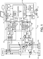
- a branch current monitor 20 arranged to monitor the voltage and current in a plurality of branch circuits comprises, generally, a data processing module 22, a current module 24 and a voltage module 26.
- the branch current monitor 20 is preferably housed in a housing and/or the data processing module 22 is preferably housed in a housing and/or the current module 24 is preferably housed in a housing and/or the voltage module is preferably housed in a housing.
- the branch current monitor and/or the data processing module and/or the current module and/or the voltage module includes one or more connectors suitable to detachably connect a separate power meter to sense electrical properties of the branch current monitor and/or the data processing module and/or the current module and/or the voltage module.
- the data processing module 22 comprises a data processing unit 30 which, typically, comprises at least one microprocessor or digital signal processor (DSP).
- DSP digital signal processor
- the data processing unit 30 reads and stores data received periodically from the voltage module and the current module, and uses that data to calculate the current, voltage, power and other electrical parameters that are the meter's output.
- the resulting electrical parameters may be output to a display 32 for viewing at the meter or output to a communications interface 34 for transmission to another data processing system, such as a building management computer, for remote display or use in automating or managing facility functions.
- the data processing module may also include a memory 36 in which the programming instructions for the data processing unit and the data manipulated by the data processing unit may be stored.
- the branch current monitor typically includes a power supply 38 to provide power to the data processing unit and to the voltage and current modules.
- the voltage module 26 includes one or more voltage transducers 42 each typically comprising a resistor network, a voltage sampling unit 48 to sample the output of the voltage transducers and convert the analog measurements to digital data suitable for use by the data processing unit and a multiplexer 44 that periodically connects the voltage sampling unit to selected ones of the voltage transducers enabling periodic sampling of the magnitude of the voltage at each of the voltage transducers.
- each phase of the electricity supplied to a distribution panel is connected to a bus bar 23 to which are connected the circuit breakers 16 that provide a conductive interconnection to each of the respective loads, by way of examples, a single-phase load 21A and a three-phase load 21 B.
- a meter for measuring three-phase power typically includes three voltage transducers 42A, 42B, 42C each connected to a respective bus bar 23A, 23B, 23C.
- a clock 40 which may be included in the data processing unit, provides periodic timing signals to trigger sampling of the outputs of the voltage transducers by the voltage sampling unit.
- the voltage module may also include a voltage sensor memory 46 in which voltage sensor characterization data, including relevant specifications and error correction data for the voltage transducers are stored. If a portion of the voltage module requires replacement, a new voltage module comprising a voltage sensor memory containing sensor characterization data for the transducers of the new module can be connected to the data processing unit.
- the data processing unit reads the data contained in the voltage sensor memory and applies the sensor characterization data when calculating the voltage from the transducer data output by the replacement voltage module.
- the current module 24 typically comprises a current sampling unit 50, a multiplexer 52 and a plurality of current transducers 54 communicatively connected to respective sensor positions 55 of the current module.
- the multiplexer 52 sequentially connects the sampling unit to the respective sensor positions enabling the sampling unit to periodically sample the output of each of the current transducers 54.
- the current sampling unit comprises an analog-to-digital converter to convert the analog sample at the output of a current transducer selected by the multiplexer, to a digital signal for acquisition by the data processing unit.
- the clock 40 also provides the periodic timing signal that triggers sampling of the current transducer outputs by the current sampling unit.
- the current module may also include a current sensor memory 56 in which are stored characterization data for the current transducers comprising the module.
- the characterization data may include transducer identities; relevant specifications, such as turns ratio; and error correction factors, for examples equations or tables enabling the phase and ratio errors to be related to a current permitting correction for magnetization induced errors.
- the characterization data may also include the type of transducers, the number of transducers, the arrangement of transducers and the order of the transducers' attachment to the respective sensor positions of the current module.
- the data processing unit queries the current sensor memory to obtain characterization data including error correction factors and relevant specifications that are used by the data processing unit in determining the monitor's output.
- monitoring current in a plurality of branch circuits requires a plurality of current transducers, each one encircling one of the branch power cable(s) 88 that connect the power distribution panel to the load(s) of the respective branch circuit.
- Current sensing may be performed by an individual current sensor, such as the current transformer 54D, which is connected to the current module.
- a branch current monitor may comprise one or more sensor strips 80 each comprising a plurality of current sensors attached to a common support, such as sensors 54A, 54B, 54C.
- the sensors 54 are preferably current transformers but other types of sensors may be used, inclusive of split-core transformers.
- Each current transformer comprises a coil of wire wound on the cross-section of a toroidal metallic or non-metallic core.
- the toroidal core is typically enclosed in a plastic housing that includes an aperture 82 enabling the power cable 88 to be extended through the central aperture of the core.
- the openings 82 defined by the toroidal cores of the transformers are preferably oriented substantially parallel to each other and oriented substantially perpendicular to the longitudinal axis 90 of the support 86.
- the sensors 54 may be arranged in substantially parallel rows on the support and the housings of the sensors in adjacent rows may be arranged to partially overlap in the direction of the longitudinal axis of the support.
- the common support maintains the current transformers in a fixed spatial relationship that preferably aligns the apertures of the toroidal coils directly opposite the connections of the power cables 88 and their respective circuit breakers 16 when the strip is installed in a distribution panel 100.
- a transient voltage suppressor 94 may be connected in parallel across the output terminals of each sensor to limit the voltage build up at the terminals when the terminals are open circuited.
- the transducer strip 80 may include the current sensor memory 56 containing characterization data for the current transformers mounted on the support 86.
- the current sensor memory may also include characterization data for the transducer strip enabling the data processing unit to determine whether a transducer strip is compatible with the remainder of the meter and whether the strip is properly connected to the data processing module. Improper connection or installation of an incompatible transducer strip may cause illumination of signaling lights or a warning message on the meter's display.
- the transducer strip 80 may comprise a current module of the power meter with one or more current transformers 54, the multiplexer 52, the current sampling unit 50 and the current sensor memory all mounted on the support 86.
- a connector 98 provides a terminus for a communication link 102 connecting the current transducer strip (current module) to the data processing module 22.
- the branch current monitor may also include one or more errant current alarms to signal an operator or data processing system that manages the facility or one or more of its operations of an errant current flow in one of the monitored branch circuits.
- an alarm annunciator is activated to notify the operator or another data processing system of the errant current flow.
- An alarm condition may be announced in one or more ways, including, without limitation, periodic or steady illumination of a light 71, sounding of an audible alarm 73, display of a message on the meter's display 32 or transmission of a signal from the communications interface 34 to a remote computer or operator.
- a commercial power distribution panel commonly supplies a substantial number of branch circuits and a branch current monitor for a distribution panel typically includes at least an equal number of current transformers.
- an exemplary electrical distribution panel includes two three-phase mains 104A, 104B which respectively are connected to main circuit breakers 106A, 106B. Each of the phases of each main is connected to a bus bar 23A, 23B, 23C.
- the three bus bars extend behind each of two rows of branch circuit breakers 16 that respectively conductively connect one of the bus bars to a conductor 54 that conducts current to the branch circuit's load(s).
- a single phase load is connected to single bus bar, a two-phase load is typically connected to two adjacent circuit breakers which are connected to respective bus bars and a three-phase load is typically connected to three adjacent circuit breakers which are each connected to one of the three bus bars.
- a two-phase load or three phase load is connected to the appropriate number of adjacent circuit breakers in the same row.
- the exemplary distribution panel has connections for 84 branch circuit conductors which can be monitored by a branch current monitor produced by Veris Industries, Inc. The branch current monitor monitors the current, voltage and energy consumption of each circuit of the distribution panel, including the mains. The accumulated information can be transmitted to a remote consumer through a communications interface or viewed locally on a local display. Data updates occur approximately every two seconds and as a circuit approaches user configured thresholds, alarms are triggered by the monitor.
- the main acquisition circuit board 108 of the branch current monitor 20 is connectable to as many as four current transformer strips or support units 80A, 80B, 80C, 80D each supporting 21 current transformers.
- the transformers of the support units are connectable to the data processing unit of the branch current monitor by communication links 102 comprising multi-conductor cables.
- the branch current monitor includes connections for six auxiliary current transformers 114 which are typically used to monitor the current in the mains. Since the voltage and phase are common for all loads connected to a bus bar, the branch current monitor also includes six voltage connections 116.
- a data channel 120 connected to the communications interface enables transmission of data captured by the branch current monitor to other data processing devices that are part of a building management system or other network.
- the main acquisition circuit board 108 is preferably housed in a housing.
- the main acquisition circuit board 108 includes one or more connectors suitable to detachably connect a separate power meter to sense electrical properties of the current and/or voltage being sensed.
- the strips or support units may be housed in a housing, in whole or in part.
- the strips or support units includes one or more connectors suitable to detachably connect a separate power meter to sense electrical properties of the current and/or voltage being sensed.
- the branch current monitor is installed in the distribution panel by mounting the current transformer strips to the panel adjacent to the rows of circuit breakers and by passing each of the branch circuit conductors 88 through a central aperture in one of the toroidal current transformers and connecting the conductors to the respective circuit breakers.
- the main acquisition board 108 is attached to the electrical panel and the multi-conductor cables 102 are connected to the board.
- the main acquisition board 108 is preferably housed in a housing.
- the mains conductors are passed through the apertures in the auxiliary current transformers and the auxiliary current transformers are connected to the main acquisition board.
- the voltage taps are connected to respective bus bars and to the main acquisition board.
- the data channel 120 is connected and the branch current monitor is ready for configuration.
- the strip unit may include a set of connectors at each general location a current sensor is desired.
- a current transformer may be included with a flexible wire within a connector at the end thereof and a connector on the strip unit. The current transformer is then detachably connectable to the connector of the strip unit.
- the current transformer may include a solid core or a split core, which is more readily interconnected to existing installed wires.
- the strip unit may include one or more power calculation circuits supported thereon.
- the data from the current transformers may be provided to the one or more power calculation circuits supported thereon together with the sensed voltage being provided by a connector from a separate voltage sensor or otherwise voltage sensed by wires interconnected to the strip unit or signal provided thereto.
- the connector may provide voltage, current, power, and other parameters to the circuit board. All or a portion of the strip unit is preferably housed in a housing. The strips unit may be housed in a housing, in whole or in part. In some embodiments, the strip unit includes one or more connectors suitable to detachably connect a separate power meter to sense electrical properties of the strip unit.
- FIG. 6 another embodiment includes a set of one or more connector boards 400 in addition to or as an alternative to the strip units.
- Each of the connector boards may include a set of connectors 410 that may be used to interconnect a current transformer thereto.
- Each of the connector boards may include a connector 420 that interconnects the connector board to the circuit board 108.
- Each of the connector boards may be labeled with numbering, such as 1 through 14 or 1 through 42, and 15 through 28 or 42 through 84. Often groups of three connectors are grouped together as a three phase circuit, thus connectors 1 through 42 may be 14 three phase circuits. For example, the connector board with the number of 1 through 14 may be intended to be connected to connector A.
- the connector board with the numbers of 15 through 28 may be intended to be connected to connector B. All or a portion of the connector board is preferably housed in a housing. In some embodiments, the connector board includes one or more connectors suitable to detachably connect a separate power meter to sense electrical properties of the connector board.
- FIG. 7 another embodiment of a power meter 200 is housed in a housing 211 formed by a front bezel 212 and a back cover 213 that snap together.
- the front bezel 212 may be bonded to a user-interface panel 214 that contains four manually operable pushbuttons 215a-215d and a central window 216 for viewing a display 217, such as an LCD, attached to the bezel 212.
- Behind the display 217 is a printed circuit board 218 (see FIG. 8 ) that has multiple terminal blocks 219a-219e and associated circuitry 220 mounted on one or both sides of the board 218.
- the terminal blocks 219a and 219b are used to connect the circuitry 220 to a control power supply and voltage input lines, respectively.
- the voltage lines may be from the power panel or from the wire to the load(s).
- the same voltage lines for example from the power panel or the wire to the load, may further be extended to pass through a respective current transformer to sense the current therein.
- a respective current sensor of a set of one or more current transformers may encircle a respective wire to a load, where the wires from the respective current transformer being interconnected to suitable terminals of one or more of the terminal blocks. In this manner, the power meter is capable of sensing or otherwise receiving signals representative of the voltage and current in the wires to the load(s).
- Terminal block 219c may be used to connect digital outputs of the circuitry 220, such as demand sync signals, alarm signals or external control signals, to relays, motors, meters or other devices.
- Terminal block 129d may be an RS485 port used for communicating with a monitoring and control system and can be daisy chained to multiple devices.
- Terminal block 219e may be used to receive digital inputs for determining circuit breaker status, counting pulses, counting motor starts, accepting demand sync pulses, and/or input metering.
- the terminal blocks 219a-219e and the circuitry 220 may be used to monitor either a single-phase, a two-phase, and/or a three-phase electrical power distribution system.
- the meter is used to measure currents and voltages and report in real time their root-mean-square values, which includes values for all three phases and neutral in the case of a three-phase power distribution system.
- the meter also typically calculates power factor, real power, reactive power and other electrical parameters.
- the housing 211 includes one or more connectors suitable to detachably connect a separate power meter to sense electrical properties of the current and/or voltage being sensed.
- the power meter 300 may include an alphanumeric display 302 to display information, such as power usage and the type thereof.
- the power meter 300 may include an alarm light 304 when an alarm condition occurs.
- the power meter 300 may include a set of configuration buttons 306.
- the power meter may include a set of voltage inputs, such as voltage A 308A, voltage B 308B, voltage C 308C, and voltage neutral 308D.
- the power meter 300 may also include an earth ground 310A and control power 310B.
- the power meter 300 may sense the current by using current transformers that are respectively interconnected to current sensor input phase A 312A, current sensor input phase B 312B, and/or current sensor input phase C 312C.
- the power meter 300 may have a set of outputs, such as a normally closed phase loss alarm 314A, a normally open pulse output representative of energy usage 314B, and other outputs 314C.
- the power meter 300 includes one or more connectors suitable to detachably connect a separate power meter to sense electrical properties of the current and/or voltage being sensed.
- the power meter may determine one or more of the following electrical parameters for one or more phases of the input, such as real energy, total instantaneous real power, total instantaneous reactive power, total instantaneous apparent power, total power factor, voltage L-L, voltage average, voltage L-N, current, real power, power factor, voltage phases A-B/B-C/A-C/A-N/B-N/C-N, instantaneous current, frequency, apparent energy consumption, reactive energy consumption, apparent power, reactive power, total real power, total reactive power, total apparent power, etc.
- the power meter may be electrically connected in series with the loads, if desired. As illustrated in FIG. 1 through FIG. 10 , the power meter may be in many different configurations and form factors. All or portions of the power meter is/are preferably housed in a housing. Whether housed in a housing or not housed in a housing, all or portions of the power meter preferably include one or more connectors suitable to detachably connect a separate power meter to sense electrical properties of the power meter, such as the voltage and/or current so that the additional power meter may determine power measurements.
- phase A (23A) and B (23B) may be reversed on the connection on one side of the panel (e.g., left side) while being properly connected on the other side of the panel (e.g., right side) to the main acquisition board.
- the main acquisition board which should associate a selected set of power conductors with phase A will actually be associating the selected set of power conductors to phase B, and the main acquisition board which should associate a selected set of power conductors with phase B will actually be associating the selected set of power conductors to phase A. This will result in improper power calculations by the main acquisition board and other electrical characteristics.
- the installer of the system may misconnect one or more of the power conductors through the current transformer to the associated circuit breaker and thus improperly align one or more power conductors with the corresponding circuit breaker.
- power conductor 88A and 88B may be reversed on the connection to the corresponding circuit breaker, which also change relationships the phase relationships of a multi-phase connection.
- the main acquisition board which should associate one or more power conductors with phase A will actually be associating the one or more power conductors with phase B
- the main acquisition board which should associate one or more of power conductors with phase B will actually be associating the one or more power conductors to phase A. This will result in improper power calculations by the main acquisition board and other electrical characteristics, in addition to improper association of the current measurements with the associated load in the case that the power conductors are interconnected to different loads.
- circuit breaker 16A may be reversed from the anticipated connection to bus bar 23A to a connection to bus bar 23B, and circuit breaker 16B may be reversed from the anticipated connection to bus bar 23B to a connection to bus bar 23A, which changes the phases of a multi-phase connection.
- the main acquisition board which should associate one or more circuit breakers with phase A will actually be associating the one or more power conductors to phase B, and the main acquisition board which should associate one or more of circuit breakers with phase B will actually be associating the one or more power conductors to phase A.
- This will result in improper power calculations by the main acquisition board and other electrical characteristics, in addition to improper association of the current measurements with the associated load in the case that the power conductors are interconnected to different loads.
- the installer of the power panel may program configuration data into within the main acquisition board (or otherwise programmed into an interconnected network device) that aligns particular power conductors and their associated sensed current levels sensed by particular current transformers, with particular bus bars may include errors, thus improperly align the power conductors with the corresponding bus bars and/or sensed current levels.
- the configuration data may be incorrect and result in errors in the data calculations. For example, circuit breakers 9 and 9 are both improperly labeled as phase C and circuit breakers 4 and 5 are both improperly labeled voltage 23A and 23A.
- a modified branch energy meter preferably includes a non-contact voltage sensor 800 included together with one or more of the current transformers.
- each of the current transformers includes an associated non-contact voltage sensor 800 to sense the voltage within the respective power conductor of the current transformer.
- the non-contact voltage sensor may use any suitable technology, such as for example, a capacitive coupling technique.
- the non-contact voltage sensor may be affixed to the exterior of the housing of the current transformer, may be enclosed within the exterior of the housing of the current transformer, or may be located at another suitable location to sense the voltage within the power conductor.
- the output of each of the non-contact voltage sensors is preferably provided to the main acquisition board with conductors on the supporting board of the current transformers and the flexible interconnect. Further, the output of each of the current transformers is preferably provided to the main acquisition board.
- the output from the non-contact voltage sensors provide a signal indicating the magnitude of the voltage levels (e.g., 110 or 220 volts) and the nature of the voltage waveform (60 hertz or 120 hertz) together with its waveform (which includes some level based information).
- the main acquisition board may provide the output of the current transformers to a network based computing device, if desired.
- the main acquisition board may provide the output of the non-contact voltage transformers to a network based computing device, if desired.
- the network based computing device may, if desired, determine the power usage for single phase, two phase, and/or three phase devices based upon the respective current(s) and voltage(s). Also, the main acquisition board may, if desired, determine the power usage for single phase, two phase, and/or three phase devices based upon the output of the current transformers and the corresponding non-contact voltage sensors. As it may be observed, by using the non-contact voltage sensors together with the current transformers, both sensing the electrical properties of the same respective power conductor, the corresponding voltage and current measurements are automatically aligned and therefore configuration errors are significantly reduced.
- one or more non-contact voltage sensors may be located in a position proximate one or more of the current transformers, although not necessarily supported by the current transformer and/or a housing enclosing a portion of the current transformer and/or a housing supporting the current transformer.
- each of the non-contact voltage sensors may be located in a position proximate a corresponding current transformer.
- the non-contact voltage sensors may be supported by the circuit board and electrically connected to the circuits supported by the circuit boards.
- each of the non-contact current sensors are arranged to primarily sense the voltage within a corresponding power conductor.
- a plurality of non-contact voltage sensors may be used to determine the corresponding voltage in a power conductor in a manner that reduces the cross talk from other proximate power conductors by using the output of a plurality of non-contact voltage sensors.
- one or more of the non-contact voltage sensors may be associated with a plurality of different power conductors, if desired.
- a modified branch energy meter preferably includes a non-contact voltage sensors 800 included together with respective ones of the current transformers.
- each of the current transformers includes an associated non-contact voltage sensor to sense the voltage within the respective power conductor of the current transformer.
- the non-contact voltage sensor may use any suitable technology, such as for example, a capacitive coupling technique.
- the output of each of the non-contact voltage sensors is preferably provided to the main acquisition board.
- the branch energy meter includes a voltage connection from the main acquisition board to each of the corresponding bus bars, such as bus bars 23A, 23B, and/or 23C. Further, the output of each of the current transformers is preferably provided to the main acquisition board.
- the non-contact voltage sensors may be relatively accurate, they may also be selected to be relatively inaccurate which tends to be less expensive while still providing a general indication of the magnitude of the voltage signal and/or the general nature of the voltage waveform. In this manner, the non-contact voltage sensors provide a generalized indication of the respective voltage waveform within the power conductor.
- the main acquisition board may receive accurate voltage connections from the bus bars 23A, 23B, and/or 23C. Each of the relatively inaccurate non-contact voltage measurements may be compared against one or more of the bus bars 23A, 23B, and/or 23C to determine the correct alignment of each power conductor with one of the voltage phases.
- the main acquisition board may provide the output of the current transformers to a network based computing device, if desired.
- the main acquisition board may provide the output of the non-contact voltage transformers to a network based computing device, if desired.
- the network based computing device may, if desired, determine the power usage for single phase, two phase, and/or three phase devices. Also, the main acquisition board may, if desired, determine the power usage for single phase, two phase, and/or three phase devices based upon the output of the current transformers and the corresponding non-contact voltage sensors and/or the bus bar voltage connections.
- the system may flag those configuration errors for the installer to correct.
- the system may reassign particular voltage measurements from the bus bars to the appropriate current transformer(s). In this manner, the configuration errors may be reduced.
- the current transformers together with the non-contact voltage sensor are interconnected to a supporting circuit board using a flexible interconnection.
- the flexible interconnection is detachably interconnected to the board, such as using a detachable connector, so that selected ones of the current transformers may be selectively replaced.
- the signals from the current transformer and the non-contact voltage sensors are provided, by way of the circuit board, to the main acquisition board or other computing device.
- the spacing of the current transformers is substantially consistent with the spacing of the circuit breakers of the panel.
- a set of one or more conductor boards 400 may be used to or as an alternative to the strip units.
- Each of the connector boards may include a set of connectors 410 that may be used to interconnect a current transformer thereto.
- each of the current transformers preferably includes a non-contact voltage sensor 800 and is electorally interconnected with one or more flexible wires to the connector board with a connector attached thereto.
- the current transformers are grouped in sets of three for a three phase circuit and preferably include a set of three non-contact voltage sensors 800 and is electorally interconnected with one or more flexible wires to the connector board with a connector attached thereto.
- the connector board may, if desired, determine the power usage for each power conductor based upon data from the current transformer and non-contact voltage sensor or a direct connected voltage sensor to the bus bar, if desired.
- Each of the connector boards may include a connector 420 that interconnects the connector board to the circuit board 108.
- Each of the connector boards may be labeled with numbering, such as 1 through 14 or 1 through 42, and 15 through 28 or 42 through 84. Often groups of three connectors are grouped together as a three phase circuit, thus connectors 1 through 42 may be 14 three phase circuits.
- the connector board with the number of 1 through 14 may be intended to be connected to connector A.
- the connector board includes one or more connectors suitable to detachably connect a separate power meter to sense electrical properties of the connector board.
- FIG. 20 another embodiment of a power meter 200 is housed in a housing 211 formed by a front bezel 212 and a back cover 213 that snap together, as illustrated in FIG. 7 .
- the front bezel 212 may be bonded to a user-interface panel 214 that contains four manually operable pushbuttons 215a-215d and a central window 216 for viewing a display 217, such as an LCD, attached to the bezel 212.
- Behind the display 217 is a printed circuit board 218 (see FIG. 21 ) that has multiple terminal blocks 219a-219e and associated circuitry 220 mounted on one or both sides of the board 218, as illustrated in FIG. 8 .
- the terminal blocks 219a and 219b are used to connect the circuitry 220 to a control power supply and voltage input lines, respectively.
- the voltage lines may be from the power panel or from the wire to the load(s).
- the same voltage lines for example from the power panel or the wire to the load, may further be extended to pass through a respective current transformer to sense the current therein.
- a respective current sensor of a set of one or more current transformers may encircle a respective wire to a load, where the wires from the respective current transformer being interconnected to suitable terminals of one or more of the terminal blocks. In this manner, the power meter is capable of sensing or otherwise receiving signals representative of the voltage and current in the wires to the load(s).
- Terminal block 219c may be used to connect digital outputs of the circuitry 220, such as demand sync signals, alarm signals or external control signals, to relays, motors, meters or other devices.
- Terminal block 129d may be an RS485 port used for communicating with a monitoring and control system and can be daisy chained to multiple devices.
- Terminal block 219e may be used to receive digital inputs for determining circuit breaker status, counting pulses, counting motor starts, accepting demand sync pulses, and/or input metering.
- the terminal blocks 219a-219e and the circuitry 220 may be used to monitor either a single-phase, a two-phase, and/or a three-phase electrical power distribution system.
- the meter is used to measure currents and voltages and report in real time their root-mean-square values, which includes values for all three phases and neutral in the case of a three-phase power distribution system.
- the meter also typically calculates power factor, real power, reactive power and other electrical parameters.
- the housing 211 includes one or more connectors suitable to detachably connect a separate power meter to sense electrical properties of the current and/or voltage being sensed.
- a particular load may have many operational and non-operational states associated with it. For example, in an operational state a particular load may be consuming an insubstantial amount of power, such as no power, when the load is not being used or otherwise in an idle state.
- the current sensed on one or more power conductors (such as one conductor for a single phase load, such as two conductors for a two phase load, and such as three conductors for a three phase load) will be zero or otherwise an insubstantial amount. In such case, the amount of current sensed will be substantially lower than a value that would be associated with normal operation of the load.
- the voltage level sensed to the load such as by the non-contact voltage sensor, will remain at a level typically associated with normal operation of the load. For example, this may be generally 120 volts, generally 240, volts, or otherwise.
- a particular load may be consuming an insubstantial amount of power, such as no power, when the load is not operational or in an alarm related condition.
- the current sensed on one or more power conductors (such as one conductor for a single phase load, such as two conductors for a two phase load, and such as three conductors for a three phase load) will be zero or otherwise an insubstantial amount. In such case, the amount of current sensed will be substantially lower than a value that would be associated with normal operation of the load such as zero.
- the voltage level sensed to the load such as by the non-contact voltage sensor, will be zero or an insubstantial amount.
- the amount of voltage sensed will be substantially lower than a value that would be associated with normal operation of the load such as zero.
- the operational state is determined for a particular load (e.g., insubstantial current level combined with a normal load level), and it is desirable to inspect the operation of the particular load, a technician may be dispatched to the load to determine what the likely cause of the operation state is.
- a technician may be dispatched to the circuit panel to reset the circuit breaker.
- the power meter may provide an indication of the operational and non-operational state of one or more loads, such as whether the device is in an alarm condition and/or a particular type of alarm condition.
- the indication may be provided as a signal to a controller and/or as a register within the power meter that is accessible by the power meter or a remote controller, and/or a visual signal, and/or audio signal, and/or any other manner.
- the current sensor may be any suitable technique, including non-toroidal cores.
Landscapes
- Physics & Mathematics (AREA)
- General Physics & Mathematics (AREA)
- Engineering & Computer Science (AREA)
- Power Engineering (AREA)
- Distribution Board (AREA)
- Measurement Of Current Or Voltage (AREA)
Abstract
Description
- The present invention relates to an energy metering system, in particular a phase aligned energy metering system.
- The total power consumption of a building or other facility is monitored by the electric utility with a power meter located between the utility's distribution transformer and the facility's power distribution panel. However, in many instances it is desirable to sub-meter or attribute the facility's power usage and cost to different occupancies, buildings, departments, or cost centers within the facility or to monitor the power consumption of individual loads or groups of loads, such as motors, lighting, heating units, cooling units, machinery, etc. These single phase or multi-phase electrical loads are typically connected to one or more of the branch circuits that extend from the facility's power distribution panel. While a power meter may be installed at any location between a load and the distribution panel, it is often advantageous to install a power meter capable of monitoring a plurality of circuits proximate the power distribution panel to provide centralized monitoring of the various loads powered from the panel.
- Digital branch current monitors may incorporate data processing systems that can monitor a plurality of circuits and determine a number of parameters related to electricity consumption by the individual branch circuits or groups of circuits. A branch current monitor for measuring electricity consumption by respective branch circuits comprises a plurality of voltage and current transducers that are periodically read by the monitor's data processing unit which, in a typical branch current monitor, comprises one or more microprocessors or digital signal processors (DSP). For example, a branch current monitor from Veris Industries, Inc. enables up to ninety circuits to be monitored with a single meter and utilizes the MODBUS® RTU network communication interface to enable remote monitoring as part of a building or facility management system. The data processing unit periodically reads and stores the outputs of the transducers quantifying the magnitudes of current and voltage samples and, using that data, calculates the current, voltage, power, and other electrical parameters, such as active power, apparent power and reactive power that quantify the distribution and consumption of electricity. The calculated parameters are typically output to a display for immediate viewing or transmitted from the meter's communication interface to another data processing system, such as a building management computer for remote display or further processing, for example formulating instructions to the facility's automated equipment.
- The voltage transducers of digital branch current monitors commonly comprise a voltage divider network that is connected to a conductor in which the voltage will be measured. The power distribution panel provides a convenient location for connecting the voltage transducers because typically each phase of the electricity is delivered to the power distribution panel on a separate bus bar and the voltage and phase is the same for all loads attached to the respective bus bar. Interconnection of a voltage transducer and the facility's wiring is facilitated by wiring connections in the power distribution panel, however, the voltage transducer(s) can be connected anywhere in the wiring that connects the supply and a load, including at the load's terminals.
- The current transducers of digital power meters typically comprise current transformers that encircle each of the power cables that connect each branch circuit to the bus bar(s) of the distribution panel.
Bowman et al., U.S. Patent No. 6,937,003 B2 , discloses a branch current monitoring system that includes a plurality of current transformers mounted on a common support facilitating installation of a branch current monitor in a power distribution panel. Installation of current transformers in electrical distribution panels is simplified by including a plurality of current transformers on a single supporting strip which can be mounted adjacent to the lines of circuit breakers in the panel. The aforementioned branch current monitor from Veris Industries, Inc. is commonly used to monitor up to four strips of current sensors; each comprising 21 current transformers on a common support. In addition, the branch current monitor provides for eight auxiliary current transformer inputs for sensing the current flow in two 3-phase mains with two neutrals and six voltage connections enabling voltage sensing in six bus bars of two 3-phase mains. - While such power metering devices tend to measure energy properties when the current and voltage measurements are phase aligned, the alignment of the voltage and current phases tends to be prone to configuration error. It is therefore an object of the invention to provide an improved phase aligned energy metering system. The object is achieved by a system according to
claim 1. - Further objects, details and advantages of the invention will become apparent from the following non-limiting description of preferred embodiments and the attached drawings.
-
- FIG. 1
- is a block diagram of an exemplary branch current monitor.
- FIG. 2
- is a perspective view of a current transformer strip for a branch current monitor.
- FIG. 3
- is a top view of the current transformer strip of
FIG. 2 . - FIG. 4
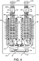
- is a front view of an exemplary electrical distribution panel and branch current monitor.
- FIG. 5
- illustrates a perspective view of another current transformer strip for a branch current monitor.
- FIG. 6
- illustrates a view of a connector board for a branch current monitor.
- FIG. 7
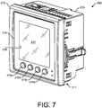
- illustrates an exemplary embodiment of a power meter.
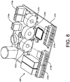
- FIG. 8
- illustrates a circuit board included within the power meter of
FIG. 7 . - FIG. 9
- illustrates another exemplary embodiment of a power meter.
- FIG. 10
- illustrates one manner of wiring a power meter for sensing voltage and current.
- FIG. 11
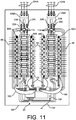
- illustrates a misaligned branch energy monitor.
- FIG. 12
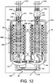
- illustrates another misaligned branch energy monitor.
- FIG. 13
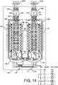
- illustrates another misaligned branch energy monitor.
- FIG. 14
- illustrates another misaligned branch energy monitor.
- FIG. 15A
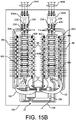
- illustrates a branch energy monitor with non-contact voltage sensors.
- FIG. 15B
- illustrates another branch energy monitor with non-contact voltage sensors.
- FIG. 16
- illustrates a branch energy monitor with contact and non-contact voltage sensors.
- FIG. 17
- illustrates phase alignment of contact and non-contact voltage sensors.
- FIG. 18
- illustrates another embodiment of a portion of a branch energy monitor.
- FIG. 19
- illustrates another embodiment of a portion of branch energy monitor.
- FIG. 20
- illustrates another embodiment of a portion of an energy monitor.
- FIG. 21
- illustrates another embodiment of a portion of the energy monitor of
FIG. 20 . - FIG. 22
- illustrates another embodiment of the energy monitor with presence detection.
- Referring in detail to the drawings where similar parts are identified by like reference numerals, and, more particularly to
FIG. 1 , a branch current monitor 20 arranged to monitor the voltage and current in a plurality of branch circuits comprises, generally, adata processing module 22, acurrent module 24 and avoltage module 26. The branch current monitor 20 is preferably housed in a housing and/or thedata processing module 22 is preferably housed in a housing and/or thecurrent module 24 is preferably housed in a housing and/or the voltage module is preferably housed in a housing. In some embodiments, the branch current monitor and/or the data processing module and/or the current module and/or the voltage module includes one or more connectors suitable to detachably connect a separate power meter to sense electrical properties of the branch current monitor and/or the data processing module and/or the current module and/or the voltage module. Thedata processing module 22 comprises adata processing unit 30 which, typically, comprises at least one microprocessor or digital signal processor (DSP). Thedata processing unit 30 reads and stores data received periodically from the voltage module and the current module, and uses that data to calculate the current, voltage, power and other electrical parameters that are the meter's output. The resulting electrical parameters may be output to adisplay 32 for viewing at the meter or output to acommunications interface 34 for transmission to another data processing system, such as a building management computer, for remote display or use in automating or managing facility functions. The data processing module may also include amemory 36 in which the programming instructions for the data processing unit and the data manipulated by the data processing unit may be stored. In addition, the branch current monitor typically includes apower supply 38 to provide power to the data processing unit and to the voltage and current modules. - The
voltage module 26 includes one or more voltage transducers 42 each typically comprising a resistor network, avoltage sampling unit 48 to sample the output of the voltage transducers and convert the analog measurements to digital data suitable for use by the data processing unit and amultiplexer 44 that periodically connects the voltage sampling unit to selected ones of the voltage transducers enabling periodic sampling of the magnitude of the voltage at each of the voltage transducers. Typically, each phase of the electricity supplied to a distribution panel is connected to a bus bar 23 to which are connected thecircuit breakers 16 that provide a conductive interconnection to each of the respective loads, by way of examples, a single-phase load 21A and a three-phase load 21 B. Since the voltage and phase supplied to all commonly connected loads is the same, a meter for measuring three-phase power typically includes threevoltage transducers respective bus bar clock 40, which may be included in the data processing unit, provides periodic timing signals to trigger sampling of the outputs of the voltage transducers by the voltage sampling unit. The voltage module may also include avoltage sensor memory 46 in which voltage sensor characterization data, including relevant specifications and error correction data for the voltage transducers are stored. If a portion of the voltage module requires replacement, a new voltage module comprising a voltage sensor memory containing sensor characterization data for the transducers of the new module can be connected to the data processing unit. The data processing unit reads the data contained in the voltage sensor memory and applies the sensor characterization data when calculating the voltage from the transducer data output by the replacement voltage module. - The
current module 24 typically comprises acurrent sampling unit 50, amultiplexer 52 and a plurality ofcurrent transducers 54 communicatively connected torespective sensor positions 55 of the current module. Themultiplexer 52 sequentially connects the sampling unit to the respective sensor positions enabling the sampling unit to periodically sample the output of each of thecurrent transducers 54. The current sampling unit comprises an analog-to-digital converter to convert the analog sample at the output of a current transducer selected by the multiplexer, to a digital signal for acquisition by the data processing unit. Theclock 40 also provides the periodic timing signal that triggers sampling of the current transducer outputs by the current sampling unit. The current module may also include acurrent sensor memory 56 in which are stored characterization data for the current transducers comprising the module. The characterization data may include transducer identities; relevant specifications, such as turns ratio; and error correction factors, for examples equations or tables enabling the phase and ratio errors to be related to a current permitting correction for magnetization induced errors. The characterization data may also include the type of transducers, the number of transducers, the arrangement of transducers and the order of the transducers' attachment to the respective sensor positions of the current module. At start up, the data processing unit queries the current sensor memory to obtain characterization data including error correction factors and relevant specifications that are used by the data processing unit in determining the monitor's output. - Referring also to
FIGS. 2, 3 , and4 , monitoring current in a plurality of branch circuits requires a plurality of current transducers, each one encircling one of the branch power cable(s) 88 that connect the power distribution panel to the load(s) of the respective branch circuit. Current sensing may be performed by an individual current sensor, such as thecurrent transformer 54D, which is connected to the current module. On the other hand, a branch current monitor may comprise one or more sensor strips 80 each comprising a plurality of current sensors attached to a common support, such assensors sensors 54 are preferably current transformers but other types of sensors may be used, inclusive of split-core transformers. Each current transformer comprises a coil of wire wound on the cross-section of a toroidal metallic or non-metallic core. The toroidal core is typically enclosed in a plastic housing that includes anaperture 82 enabling thepower cable 88 to be extended through the central aperture of the core. Theopenings 82 defined by the toroidal cores of the transformers are preferably oriented substantially parallel to each other and oriented substantially perpendicular to thelongitudinal axis 90 of thesupport 86. To provide a more compact arrangement of sensors, thesensors 54 may be arranged in substantially parallel rows on the support and the housings of the sensors in adjacent rows may be arranged to partially overlap in the direction of the longitudinal axis of the support. To facilitate routing the power cables of the branch circuits through the cores of the current transformers, the common support maintains the current transformers in a fixed spatial relationship that preferably aligns the apertures of the toroidal coils directly opposite the connections of thepower cables 88 and theirrespective circuit breakers 16 when the strip is installed in adistribution panel 100. For protection from electrical shock, atransient voltage suppressor 94 may be connected in parallel across the output terminals of each sensor to limit the voltage build up at the terminals when the terminals are open circuited. - The
transducer strip 80 may include thecurrent sensor memory 56 containing characterization data for the current transformers mounted on thesupport 86. The current sensor memory may also include characterization data for the transducer strip enabling the data processing unit to determine whether a transducer strip is compatible with the remainder of the meter and whether the strip is properly connected to the data processing module. Improper connection or installation of an incompatible transducer strip may cause illumination of signaling lights or a warning message on the meter's display. In addition, thetransducer strip 80 may comprise a current module of the power meter with one or morecurrent transformers 54, themultiplexer 52, thecurrent sampling unit 50 and the current sensor memory all mounted on thesupport 86. Aconnector 98 provides a terminus for acommunication link 102 connecting the current transducer strip (current module) to thedata processing module 22. - The branch current monitor may also include one or more errant current alarms to signal an operator or data processing system that manages the facility or one or more of its operations of an errant current flow in one of the monitored branch circuits. When a current having a magnitude greater or lesser than a respective alarm current limit is detected in one of the branch circuits an alarm annunciator is activated to notify the operator or another data processing system of the errant current flow. An alarm condition may be announced in one or more ways, including, without limitation, periodic or steady illumination of a light 71, sounding of an
audible alarm 73, display of a message on the meter'sdisplay 32 or transmission of a signal from thecommunications interface 34 to a remote computer or operator. - A commercial power distribution panel commonly supplies a substantial number of branch circuits and a branch current monitor for a distribution panel typically includes at least an equal number of current transformers. Referring to
FIG. 4 , an exemplary electrical distribution panel includes two three-phase mains main circuit breakers bus bar branch circuit breakers 16 that respectively conductively connect one of the bus bars to aconductor 54 that conducts current to the branch circuit's load(s). A single phase load is connected to single bus bar, a two-phase load is typically connected to two adjacent circuit breakers which are connected to respective bus bars and a three-phase load is typically connected to three adjacent circuit breakers which are each connected to one of the three bus bars. Typically, a two-phase load or three phase load is connected to the appropriate number of adjacent circuit breakers in the same row. The exemplary distribution panel has connections for 84 branch circuit conductors which can be monitored by a branch current monitor produced by Veris Industries, Inc. The branch current monitor monitors the current, voltage and energy consumption of each circuit of the distribution panel, including the mains. The accumulated information can be transmitted to a remote consumer through a communications interface or viewed locally on a local display. Data updates occur approximately every two seconds and as a circuit approaches user configured thresholds, alarms are triggered by the monitor. - As illustrated in
FIG. 4 , the mainacquisition circuit board 108 of the branch current monitor 20 is connectable to as many as four current transformer strips orsupport units communication links 102 comprising multi-conductor cables. In addition, the branch current monitor includes connections for six auxiliarycurrent transformers 114 which are typically used to monitor the current in the mains. Since the voltage and phase are common for all loads connected to a bus bar, the branch current monitor also includes sixvoltage connections 116. Adata channel 120 connected to the communications interface enables transmission of data captured by the branch current monitor to other data processing devices that are part of a building management system or other network. The mainacquisition circuit board 108 is preferably housed in a housing. In some embodiments, the mainacquisition circuit board 108 includes one or more connectors suitable to detachably connect a separate power meter to sense electrical properties of the current and/or voltage being sensed. The strips or support units may be housed in a housing, in whole or in part. In some embodiments, the strips or support units includes one or more connectors suitable to detachably connect a separate power meter to sense electrical properties of the current and/or voltage being sensed. - The branch current monitor is installed in the distribution panel by mounting the current transformer strips to the panel adjacent to the rows of circuit breakers and by passing each of the
branch circuit conductors 88 through a central aperture in one of the toroidal current transformers and connecting the conductors to the respective circuit breakers. Themain acquisition board 108 is attached to the electrical panel and themulti-conductor cables 102 are connected to the board. Themain acquisition board 108 is preferably housed in a housing. The mains conductors are passed through the apertures in the auxiliary current transformers and the auxiliary current transformers are connected to the main acquisition board. The voltage taps are connected to respective bus bars and to the main acquisition board. Thedata channel 120 is connected and the branch current monitor is ready for configuration. - Referring to
FIG. 5 , in another embodiment, the strip unit may include a set of connectors at each general location a current sensor is desired. A current transformer may be included with a flexible wire within a connector at the end thereof and a connector on the strip unit. The current transformer is then detachably connectable to the connector of the strip unit. The current transformer may include a solid core or a split core, which is more readily interconnected to existing installed wires. If desired, the strip unit may include one or more power calculation circuits supported thereon. For example, the data from the current transformers may be provided to the one or more power calculation circuits supported thereon together with the sensed voltage being provided by a connector from a separate voltage sensor or otherwise voltage sensed by wires interconnected to the strip unit or signal provided thereto. As a result of this configuration, the connector may provide voltage, current, power, and other parameters to the circuit board. All or a portion of the strip unit is preferably housed in a housing. The strips unit may be housed in a housing, in whole or in part. In some embodiments, the strip unit includes one or more connectors suitable to detachably connect a separate power meter to sense electrical properties of the strip unit. - Referring to
FIG. 6 , another embodiment includes a set of one ormore connector boards 400 in addition to or as an alternative to the strip units. Each of the connector boards may include a set ofconnectors 410 that may be used to interconnect a current transformer thereto. Each of the connector boards may include aconnector 420 that interconnects the connector board to thecircuit board 108. Each of the connector boards may be labeled with numbering, such as 1 through 14 or 1 through 42, and 15 through 28 or 42 through 84. Often groups of three connectors are grouped together as a three phase circuit, thusconnectors 1 through 42 may be 14 three phase circuits. For example, the connector board with the number of 1 through 14 may be intended to be connected to connector A. For example, the connector board with the numbers of 15 through 28 may be intended to be connected to connector B. All or a portion of the connector board is preferably housed in a housing. In some embodiments, the connector board includes one or more connectors suitable to detachably connect a separate power meter to sense electrical properties of the connector board. - Referring to
FIG. 7 , another embodiment of apower meter 200 is housed in ahousing 211 formed by afront bezel 212 and aback cover 213 that snap together. Thefront bezel 212 may be bonded to a user-interface panel 214 that contains four manuallyoperable pushbuttons 215a-215d and acentral window 216 for viewing adisplay 217, such as an LCD, attached to thebezel 212. Behind thedisplay 217 is a printed circuit board 218 (seeFIG. 8 ) that has multipleterminal blocks 219a-219e and associatedcircuitry 220 mounted on one or both sides of theboard 218. The terminal blocks 219a and 219b are used to connect thecircuitry 220 to a control power supply and voltage input lines, respectively. For example, the voltage lines may be from the power panel or from the wire to the load(s). In addition the same voltage lines, for example from the power panel or the wire to the load, may further be extended to pass through a respective current transformer to sense the current therein. Also, a respective current sensor of a set of one or more current transformers may encircle a respective wire to a load, where the wires from the respective current transformer being interconnected to suitable terminals of one or more of the terminal blocks. In this manner, the power meter is capable of sensing or otherwise receiving signals representative of the voltage and current in the wires to the load(s).Terminal block 219c may be used to connect digital outputs of thecircuitry 220, such as demand sync signals, alarm signals or external control signals, to relays, motors, meters or other devices. Terminal block 129d may be an RS485 port used for communicating with a monitoring and control system and can be daisy chained to multiple devices.Terminal block 219e may be used to receive digital inputs for determining circuit breaker status, counting pulses, counting motor starts, accepting demand sync pulses, and/or input metering. The terminal blocks 219a-219e and the circuitry 220 (simplified for purposes of illustration) may be used to monitor either a single-phase, a two-phase, and/or a three-phase electrical power distribution system. Typically the meter is used to measure currents and voltages and report in real time their root-mean-square values, which includes values for all three phases and neutral in the case of a three-phase power distribution system. The meter also typically calculates power factor, real power, reactive power and other electrical parameters. In some embodiments, thehousing 211 includes one or more connectors suitable to detachably connect a separate power meter to sense electrical properties of the current and/or voltage being sensed. - Referring to
FIG. 9 , another embodiment of apower meter 300 housed within a housing suitable to be mounted to a standard 35 mm DIN rail or screw-mounted to the interior surface of an enclosure. Thepower meter 300 may include analphanumeric display 302 to display information, such as power usage and the type thereof. Thepower meter 300 may include analarm light 304 when an alarm condition occurs. Thepower meter 300 may include a set ofconfiguration buttons 306. The power meter may include a set of voltage inputs, such asvoltage A 308A,voltage B 308B,voltage C 308C, and voltage neutral 308D. Thepower meter 300 may also include anearth ground 310A and controlpower 310B. Thepower meter 300 may sense the current by using current transformers that are respectively interconnected to current sensor input phase A 312A, current sensorinput phase B 312B, and/or current sensorinput phase C 312C. Thepower meter 300 may have a set of outputs, such as a normally closedphase loss alarm 314A, a normally open pulse output representative ofenergy usage 314B, andother outputs 314C. In some embodiments, thepower meter 300 includes one or more connectors suitable to detachably connect a separate power meter to sense electrical properties of the current and/or voltage being sensed. - Referring to
FIG. 10 , an exemplary wiring diagram for a 3-phase 3-wire current transformer with a neural is illustrated. By way of example, the power meter may determine one or more of the following electrical parameters for one or more phases of the input, such as real energy, total instantaneous real power, total instantaneous reactive power, total instantaneous apparent power, total power factor, voltage L-L, voltage average, voltage L-N, current, real power, power factor, voltage phases A-B/B-C/A-C/A-N/B-N/C-N, instantaneous current, frequency, apparent energy consumption, reactive energy consumption, apparent power, reactive power, total real power, total reactive power, total apparent power, etc. - In some embodiments, the power meter may be electrically connected in series with the loads, if desired. As illustrated in
FIG. 1 through FIG. 10 , the power meter may be in many different configurations and form factors. All or portions of the power meter is/are preferably housed in a housing. Whether housed in a housing or not housed in a housing, all or portions of the power meter preferably include one or more connectors suitable to detachably connect a separate power meter to sense electrical properties of the power meter, such as the voltage and/or current so that the additional power meter may determine power measurements. - Referring again to
FIG. 4 thoughFIG. 9 , the installer of the system may misconnect one or more of the bus bars 23A, 23B, and/or 23C to the main acquisition board and accordingly the voltages would in most likely be improperly aligned with the current being provided by the corresponding power conductor. Referring also toFIG. 11 , for example, phases A (23A) and B (23B) may be reversed on the connection on one side of the panel (e.g., left side) while being properly connected on the other side of the panel (e.g., right side) to the main acquisition board. Typically, the main acquisition board which should associate a selected set of power conductors with phase A will actually be associating the selected set of power conductors to phase B, and the main acquisition board which should associate a selected set of power conductors with phase B will actually be associating the selected set of power conductors to phase A. This will result in improper power calculations by the main acquisition board and other electrical characteristics. - Referring again to
FIG. 4 though FIG. 9A , the installer of the system may misconnect one or more of the power conductors through the current transformer to the associated circuit breaker and thus improperly align one or more power conductors with the corresponding circuit breaker. Referring also toFIG. 12 , for example,power conductor - Referring again to
FIG. 4 though FIG. 9A , the installer of the power panel may misconnect one or more of the circuit breakers to a different bus bar than anticipated thus improperly align the power conductor with the corresponding bus bar. Referring also toFIG. 13 , for example,circuit breaker 16A may be reversed from the anticipated connection tobus bar 23A to a connection tobus bar 23B, andcircuit breaker 16B may be reversed from the anticipated connection tobus bar 23B to a connection tobus bar 23A, which changes the phases of a multi-phase connection. Typically, the main acquisition board which should associate one or more circuit breakers with phase A will actually be associating the one or more power conductors to phase B, and the main acquisition board which should associate one or more of circuit breakers with phase B will actually be associating the one or more power conductors to phase A. This will result in improper power calculations by the main acquisition board and other electrical characteristics, in addition to improper association of the current measurements with the associated load in the case that the power conductors are interconnected to different loads. - Referring again to
FIG. 4 thoughFIG. 9 , the installer of the power panel may program configuration data into within the main acquisition board (or otherwise programmed into an interconnected network device) that aligns particular power conductors and their associated sensed current levels sensed by particular current transformers, with particular bus bars may include errors, thus improperly align the power conductors with the corresponding bus bars and/or sensed current levels. Referring also toFIG. 14 , the configuration data may be incorrect and result in errors in the data calculations. For example,circuit breakers circuit breakers 4 and 5 are both improperly labeledvoltage - As it may be observed, there are many sources of potential errors when configuring a branch current metering system which are problematic to identify and rectify. Furthermore, these problems persist in many different configurations, such as those embodiments illustrated in
FIG. 4 through FIG. 9 . - Referring to
FIG. 15A , a modified branch energy meter preferably includes anon-contact voltage sensor 800 included together with one or more of the current transformers. Preferably, each of the current transformers includes an associatednon-contact voltage sensor 800 to sense the voltage within the respective power conductor of the current transformer. The non-contact voltage sensor may use any suitable technology, such as for example, a capacitive coupling technique. The non-contact voltage sensor may be affixed to the exterior of the housing of the current transformer, may be enclosed within the exterior of the housing of the current transformer, or may be located at another suitable location to sense the voltage within the power conductor. The output of each of the non-contact voltage sensors is preferably provided to the main acquisition board with conductors on the supporting board of the current transformers and the flexible interconnect. Further, the output of each of the current transformers is preferably provided to the main acquisition board. The output from the non-contact voltage sensors provide a signal indicating the magnitude of the voltage levels (e.g., 110 or 220 volts) and the nature of the voltage waveform (60 hertz or 120 hertz) together with its waveform (which includes some level based information). The main acquisition board may provide the output of the current transformers to a network based computing device, if desired. The main acquisition board may provide the output of the non-contact voltage transformers to a network based computing device, if desired. The network based computing device may, if desired, determine the power usage for single phase, two phase, and/or three phase devices based upon the respective current(s) and voltage(s). Also, the main acquisition board may, if desired, determine the power usage for single phase, two phase, and/or three phase devices based upon the output of the current transformers and the corresponding non-contact voltage sensors. As it may be observed, by using the non-contact voltage sensors together with the current transformers, both sensing the electrical properties of the same respective power conductor, the corresponding voltage and current measurements are automatically aligned and therefore configuration errors are significantly reduced. - Referring to
FIG. 15B , in some embodiments, one or more non-contact voltage sensors may be located in a position proximate one or more of the current transformers, although not necessarily supported by the current transformer and/or a housing enclosing a portion of the current transformer and/or a housing supporting the current transformer. Preferably, each of the non-contact voltage sensors may be located in a position proximate a corresponding current transformer. By way of example, the non-contact voltage sensors may be supported by the circuit board and electrically connected to the circuits supported by the circuit boards. Preferably, each of the non-contact current sensors are arranged to primarily sense the voltage within a corresponding power conductor. - In some embodiments, there may be more than one non-contact voltage sensor associated with a single power conductor. A plurality of non-contact voltage sensors may be used to determine the corresponding voltage in a power conductor in a manner that reduces the cross talk from other proximate power conductors by using the output of a plurality of non-contact voltage sensors. Also, one or more of the non-contact voltage sensors may be associated with a plurality of different power conductors, if desired.
- In some embodiments, there may be non-contact voltage sensors that are supported by one or more of the current transformers and non-contact voltage sensors that are not supported by the current transformers.
- Referring to
FIG. 16 , a modified branch energy meter preferably includes anon-contact voltage sensors 800 included together with respective ones of the current transformers. Preferably, each of the current transformers includes an associated non-contact voltage sensor to sense the voltage within the respective power conductor of the current transformer. The non-contact voltage sensor may use any suitable technology, such as for example, a capacitive coupling technique. The output of each of the non-contact voltage sensors is preferably provided to the main acquisition board. Also, the branch energy meter includes a voltage connection from the main acquisition board to each of the corresponding bus bars, such asbus bars - Referring to
FIG. 17 , while the non-contact voltage sensors may be relatively accurate, they may also be selected to be relatively inaccurate which tends to be less expensive while still providing a general indication of the magnitude of the voltage signal and/or the general nature of the voltage waveform. In this manner, the non-contact voltage sensors provide a generalized indication of the respective voltage waveform within the power conductor. The main acquisition board may receive accurate voltage connections from the bus bars 23A, 23B, and/or 23C. Each of the relatively inaccurate non-contact voltage measurements may be compared against one or more of the bus bars 23A, 23B, and/or 23C to determine the correct alignment of each power conductor with one of the voltage phases. - The main acquisition board may provide the output of the current transformers to a network based computing device, if desired. The main acquisition board may provide the output of the non-contact voltage transformers to a network based computing device, if desired. The network based computing device may, if desired, determine the power usage for single phase, two phase, and/or three phase devices. Also, the main acquisition board may, if desired, determine the power usage for single phase, two phase, and/or three phase devices based upon the output of the current transformers and the corresponding non-contact voltage sensors and/or the bus bar voltage connections. As it may be observed, by using the non-contact voltage sensors together with the current transformers, both sensing the electrical properties of the same respective power conductor, the corresponding voltage and current measurements are aligned and therefore configuration errors are significantly reduced. In the event that configuration errors are identified, the system may flag those configuration errors for the installer to correct. Alternatively, in the event that configuration errors are identified, the system may reassign particular voltage measurements from the bus bars to the appropriate current transformer(s). In this manner, the configuration errors may be reduced.
- Referring to
FIG. 18 , in another embodiment the current transformers together with the non-contact voltage sensor are interconnected to a supporting circuit board using a flexible interconnection. Preferably the flexible interconnection is detachably interconnected to the board, such as using a detachable connector, so that selected ones of the current transformers may be selectively replaced. The signals from the current transformer and the non-contact voltage sensors are provided, by way of the circuit board, to the main acquisition board or other computing device. Preferably the spacing of the current transformers is substantially consistent with the spacing of the circuit breakers of the panel. - Referring to
FIG. 19 , in another embodiment a set of one ormore conductor boards 400 may be used to or as an alternative to the strip units. Each of the connector boards may include a set ofconnectors 410 that may be used to interconnect a current transformer thereto. In one embodiment, each of the current transformers preferably includes anon-contact voltage sensor 800 and is electorally interconnected with one or more flexible wires to the connector board with a connector attached thereto. In another embodiment, the current transformers are grouped in sets of three for a three phase circuit and preferably include a set of threenon-contact voltage sensors 800 and is electorally interconnected with one or more flexible wires to the connector board with a connector attached thereto. The connector board may, if desired, determine the power usage for each power conductor based upon data from the current transformer and non-contact voltage sensor or a direct connected voltage sensor to the bus bar, if desired. Each of the connector boards may include aconnector 420 that interconnects the connector board to thecircuit board 108. Each of the connector boards may be labeled with numbering, such as 1 through 14 or 1 through 42, and 15 through 28 or 42 through 84. Often groups of three connectors are grouped together as a three phase circuit, thusconnectors 1 through 42 may be 14 three phase circuits. For example, the connector board with the number of 1 through 14 may be intended to be connected to connector A. For example, the connector board with the numbers of 15 through 28 may be intended to be connected to connector B. All or a portion of the connector board is preferably housed in a housing. In some embodiments, the connector board includes one or more connectors suitable to detachably connect a separate power meter to sense electrical properties of the connector board. - Referring to
FIG. 20 , another embodiment of apower meter 200 is housed in ahousing 211 formed by afront bezel 212 and aback cover 213 that snap together, as illustrated inFIG. 7 . Thefront bezel 212 may be bonded to a user-interface panel 214 that contains four manuallyoperable pushbuttons 215a-215d and acentral window 216 for viewing adisplay 217, such as an LCD, attached to thebezel 212. Behind thedisplay 217 is a printed circuit board 218 (seeFIG. 21 ) that has multipleterminal blocks 219a-219e and associatedcircuitry 220 mounted on one or both sides of theboard 218, as illustrated inFIG. 8 . The terminal blocks 219a and 219b are used to connect thecircuitry 220 to a control power supply and voltage input lines, respectively. For example, the voltage lines may be from the power panel or from the wire to the load(s). In addition the same voltage lines, for example from the power panel or the wire to the load, may further be extended to pass through a respective current transformer to sense the current therein. Also, a respective current sensor of a set of one or more current transformers may encircle a respective wire to a load, where the wires from the respective current transformer being interconnected to suitable terminals of one or more of the terminal blocks. In this manner, the power meter is capable of sensing or otherwise receiving signals representative of the voltage and current in the wires to the load(s).Terminal block 219c may be used to connect digital outputs of thecircuitry 220, such as demand sync signals, alarm signals or external control signals, to relays, motors, meters or other devices. Terminal block 129d may be an RS485 port used for communicating with a monitoring and control system and can be daisy chained to multiple devices.Terminal block 219e may be used to receive digital inputs for determining circuit breaker status, counting pulses, counting motor starts, accepting demand sync pulses, and/or input metering. The terminal blocks 219a-219e and the circuitry 220 (simplified for purposes of illustration) may be used to monitor either a single-phase, a two-phase, and/or a three-phase electrical power distribution system. Typically the meter is used to measure currents and voltages and report in real time their root-mean-square values, which includes values for all three phases and neutral in the case of a three-phase power distribution system. The meter also typically calculates power factor, real power, reactive power and other electrical parameters. In some embodiments, thehousing 211 includes one or more connectors suitable to detachably connect a separate power meter to sense electrical properties of the current and/or voltage being sensed. - Referring to
FIG. 22 , it was determined that a particular load may have many operational and non-operational states associated with it. For example, in an operational state a particular load may be consuming an insubstantial amount of power, such as no power, when the load is not being used or otherwise in an idle state. When a particular load is consuming an insubstantial amount of power, the current sensed on one or more power conductors (such as one conductor for a single phase load, such as two conductors for a two phase load, and such as three conductors for a three phase load) will be zero or otherwise an insubstantial amount. In such case, the amount of current sensed will be substantially lower than a value that would be associated with normal operation of the load. However, while the particular load is consuming an insubstantial amount of power, the voltage level sensed to the load, such as by the non-contact voltage sensor, will remain at a level typically associated with normal operation of the load. For example, this may be generally 120 volts, generally 240, volts, or otherwise. - For example, in a non-operational state a particular load may be consuming an insubstantial amount of power, such as no power, when the load is not operational or in an alarm related condition. When a particular load is consuming an insubstantial amount of power, the current sensed on one or more power conductors (such as one conductor for a single phase load, such as two conductors for a two phase load, and such as three conductors for a three phase load) will be zero or otherwise an insubstantial amount. In such case, the amount of current sensed will be substantially lower than a value that would be associated with normal operation of the load such as zero. However, while the particular load is consuming an insubstantial amount of power, the voltage level sensed to the load, such as by the non-contact voltage sensor, will be zero or an insubstantial amount. In such case, the amount of voltage sensed will be substantially lower than a value that would be associated with normal operation of the load such as zero. When both the current sensed and the voltage sensed for a particular load, sensed on the one or more power conductors for a load, it indicates an alarm condition that would be the result of tripping one or more circuit breakers to the load.
- When the operational state is determined for a particular load (e.g., insubstantial current level combined with a normal load level), and it is desirable to inspect the operation of the particular load, a technician may be dispatched to the load to determine what the likely cause of the operation state is. When the non-operational state is determined for a particular load (e.g., insubstantial current level combined with an insubstantial voltage level), and it is desirable to inspect the operation of the particular load, a technician may be dispatched to the circuit panel to reset the circuit breaker.
- The power meter may provide an indication of the operational and non-operational state of one or more loads, such as whether the device is in an alarm condition and/or a particular type of alarm condition. The indication may be provided as a signal to a controller and/or as a register within the power meter that is accessible by the power meter or a remote controller, and/or a visual signal, and/or audio signal, and/or any other manner.
- It is to be understood that the current sensor may be any suitable technique, including non-toroidal cores.
- The detailed description, above, sets forth numerous specific details to provide a thorough understanding of the present invention. However, those skilled in the art will appreciate that the present invention may be practiced without these specific details.
- In other instances, well known methods, procedures, components, and circuitry have not been described in detail to avoid obscuring the present invention.
- All the references cited herein are incorporated by reference.
- The terms and expressions that have been employed in the foregoing specification are used as terms of description and not of limitation, and there is no intention, in the use of such terms and expressions, of excluding equivalents of the features shown and described or portions thereof, it being recognized that the scope of the invention is defined and limited only by the claims that follow.
Claims (15)
- An energy metering system comprising:- a plurality of current sensors suitable to sense current levels in a respective power conductor and each of said plurality of current sensors providing a respective first signal indicating respective said current levels,- a plurality of non-contact voltage sensors suitable to sense voltage levels in a respective said power conductor and each of said plurality of non-contact voltage sensors providing a respective second signal indicating respective said voltage levels, where there is a respective pair of said current sensors and said non-contact voltage sensors associated with each of said power conductors, and- a monitoring device that receives each of said respective first signals and receives each of said respective second signals.
- The energy metering system of claim 1, wherein said monitoring device assigns said respective first signals to phases of a multi-phase circuit based upon said respective second signals.
- The energy metering system of claim 1, wherein monitoring device verifies said respective first signals to phases of a multi-phase circuit based upon said respective second signals.
- The energy metering system of claim 1, further comprising a plurality of direct contact voltage sensors suitable to sense voltage levels in a respective bus bar of a panel providing power to respective ones of said power conductor and each of said plurality of direct contact voltage sensors providing a respective third signal indicating respective said voltage levels.
- The energy metering system of claim 4, wherein there is a respective pair of said current sensors and said direct contact voltage sensors associated with each of said power conductors.
- The energy metering system of claim 1, wherein one of said non-contact voltage sensors is located at a location proximate a corresponding one of said current sensors.
- The energy metering system of claim 6, wherein another one of said non-contact voltage sensors is supported by corresponding another one of said current sensors.
- The energy metering system of claim 7, wherein said another one of said non-contact voltage sensors is supported by a housing surrounding a portion of said corresponding another one of said current sensors.
- The energy metering system of claim 1, wherein said monitoring device determines whether a corresponding load for one of said power conductors is operational or non-operational.
- The energy metering system of claim 9, wherein said corresponding load is operational if a corresponding current level is insubstantial and a corresponding voltage level is not insubstantial.
- The energy metering system of claim 10, wherein said corresponding load is non-operational if a corresponding current level is insubstantial and a corresponding voltage level is insubstantial.
- The energy metering system of claim 1, further comprising:- a contact voltage sensor suitable to sense voltage levels in said respective said power conductor and providing a respective third signal indicating respective said voltage levels; and- an energy meter that receives said first signal, said second signal, and said third signal, and determines a power level within said power conductor based upon said first signal and said third signal, while verifying that said first signal and said third signal are associated with the same said power conductor based upon said second signal.
- The energy metering system of claim 1, further comprising:- a plurality of contact voltage sensors suitable to sense voltage levels in said respective said power conductor and providing a respective third signal indicating respective said voltage levels, and- an energy meter that receives said first signals, said second signals, and said third signals, and verifies that respective pairs of said first signal and said third signal are associated with the same respective power conductor based upon a corresponding one of said second signals.
- The energy metering system of claim 1, further comprising an energy meter that receives said first signal, and said second signals, an determines a power level within said power conductor based upon said first signal and said plurality of second signals.
- The energy metering system of claim 14, wherein said second signals are based upon at least one of a magnitude of said sensed voltage levels, a frequency of said sensed voltage levels, and a plurality of said sensed voltage levels.
Applications Claiming Priority (2)
| Application Number | Priority Date | Filing Date | Title |
|---|---|---|---|
| US201762464595P | 2017-02-28 | 2017-02-28 | |
| US15/789,496 US11215650B2 (en) | 2017-02-28 | 2017-10-20 | Phase aligned branch energy meter |
Publications (1)
| Publication Number | Publication Date |
|---|---|
| EP3367111A1 true EP3367111A1 (en) | 2018-08-29 |
Family
ID=61283084
Family Applications (1)
| Application Number | Title | Priority Date | Filing Date |
|---|---|---|---|
| EP18158636.3A Pending EP3367111A1 (en) | 2017-02-28 | 2018-02-26 | Energy metering system |
Country Status (2)
| Country | Link |
|---|---|
| US (1) | US11215650B2 (en) |
| EP (1) | EP3367111A1 (en) |
Families Citing this family (12)
| Publication number | Priority date | Publication date | Assignee | Title |
|---|---|---|---|---|
| US11516899B2 (en) | 2015-05-27 | 2022-11-29 | Electro Industries/Gauge Tech | Devices, systems and methods for electrical utility submetering |
| CA3024185C (en) | 2016-05-26 | 2023-03-28 | Landis+Gyr Innovations, Inc. | Utility meter for use with distributed generation device |
| US11726632B2 (en) | 2017-07-27 | 2023-08-15 | Johnson Controls Technology Company | Building management system with global rule library and crowdsourcing framework |
| US11860202B2 (en) * | 2018-10-23 | 2024-01-02 | Ei Electronics Llc | Devices, systems and methods for meter setup verification |
| US20220043038A1 (en) * | 2018-12-17 | 2022-02-10 | Xslent Energy Technologies, Llc | Sensor-based energy management enclosure and distributed energy resource management based on sensor data |
| US10948516B2 (en) | 2019-01-10 | 2021-03-16 | Landis+Gyr Innovations, Inc. | Methods and systems for connecting and metering distributed energy resource devices |
| US11119123B2 (en) * | 2019-03-11 | 2021-09-14 | Honeywell International Inc. | Power meter with movable terminal blocks |
| US11187734B2 (en) * | 2019-05-31 | 2021-11-30 | Landis+Gyr Innovations, Inc. | Systems for electrically connecting metering devices and distributed energy resource devices |
| US11506693B2 (en) | 2019-10-11 | 2022-11-22 | Landis+Gyr Innovations, Inc. | Meter and socket for use with a distributed energy resource device |
| US11444444B2 (en) * | 2020-01-30 | 2022-09-13 | Landis+Gyr Innovations, Inc. | Arc detection antenna in electric meter systems |
| US11137421B1 (en) * | 2020-04-10 | 2021-10-05 | Schneider Electric USA, Inc. | Non-contact voltage sensing system |
| US20240012037A1 (en) * | 2022-07-08 | 2024-01-11 | Landis+Gyr Innovations, Inc. | Meter for use with a distributed energy resource |
Citations (4)
| Publication number | Priority date | Publication date | Assignee | Title |
|---|---|---|---|---|
| WO1999042844A1 (en) * | 1998-02-23 | 1999-08-26 | The University Of Sydney | Power monitoring apparatus |
| US6937003B2 (en) | 2002-03-26 | 2005-08-30 | Veris Industries, Llc | Power monitoring system |
| EP2241898A1 (en) * | 2008-02-06 | 2010-10-20 | Mitsubishi Electric Corporation | Power measuring system, measuring apparatus, load terminal, and device control system |
| US20130211751A1 (en) * | 2012-02-10 | 2013-08-15 | Daniel J. Park | System and Method for Calculating Power Using Contactless Voltage Waveform Shape Sensor |
Family Cites Families (261)
| Publication number | Priority date | Publication date | Assignee | Title |
|---|---|---|---|---|
| US1100171A (en) | 1912-10-07 | 1914-06-16 | Earl W Brown | Method of and apparatus for sampling gases. |
| US1455263A (en) | 1920-06-11 | 1923-05-15 | George G Oberfell | Method and apparatus for testing gaseous mixtures |
| US1569723A (en) | 1925-08-14 | 1926-01-12 | Gen Electric | Instrument transformer |
| US1871710A (en) | 1929-04-11 | 1932-08-16 | Westinghouse Electric & Mfg Co | Metering system |
| US1800474A (en) | 1929-10-30 | 1931-04-14 | Western Electromechanical Co I | Meter for alternating current |
| US1830541A (en) | 1930-06-20 | 1931-11-03 | Gen Electric | Instrument transformer |
| US2059594A (en) | 1935-04-02 | 1936-11-03 | Frank Massa | Electrical measuring instrument |
| US2428613A (en) | 1943-10-18 | 1947-10-07 | Gen Electric | Transformer |
| US2412782A (en) | 1944-05-26 | 1946-12-17 | Robert T Palmer | Wet bulb thermometer and thermostat |
| US2663190A (en) | 1950-11-16 | 1953-12-22 | Bell Telephone Labor Inc | Humidity indicator |
| US2746295A (en) | 1951-12-12 | 1956-05-22 | Underwood Corp | Apparatus for measuring and recording pressures indicated by manometer tubes |
| US2802182A (en) | 1954-02-01 | 1957-08-06 | Fox Prod Co | Current density responsive apparatus |
| US2852739A (en) | 1954-07-26 | 1958-09-16 | Gen Electric | Remote controlled impedance measuring circuit |
| US2943488A (en) | 1957-05-27 | 1960-07-05 | Robertshaw Fulton Controls Co | Humidistat |
| US3190122A (en) | 1960-09-01 | 1965-06-22 | Simmonds Precision Products | Mercurial capacitors for remote indication of pressure |
| US3243674A (en) | 1963-02-01 | 1966-03-29 | Ebert Gotthold | Capacitor type sensing device |
| US3287974A (en) | 1964-03-30 | 1966-11-29 | Holley Carburetor Co | Ice condition detection device |
| US3374434A (en) | 1965-09-09 | 1968-03-19 | Geodyne Corp | Inductive coupling apparatus for use in coupling to underwater electric systems and the like |
| US3493760A (en) | 1966-12-14 | 1970-02-03 | Us Army | Optical isolator for electric signals |
| US3584294A (en) | 1967-07-17 | 1971-06-08 | Fenwal Inc | A system for measuring low levels of electrical energy |
| US3512045A (en) | 1968-06-28 | 1970-05-12 | Gen Signal Corp | Ground fault responsive apparatus for electric power distribution apparatus |
| US3593078A (en) | 1969-09-08 | 1971-07-13 | North American Rockwell | Starting and operating control for an ac motor powered by a dc power supply |
| US3728705A (en) | 1970-05-04 | 1973-04-17 | Wagner Electric Corp | Lamp outage indicator |
| US3696288A (en) | 1970-05-08 | 1972-10-03 | Cameron Iron Works Inc | Optically coupled control circuit |
| DE2124345C3 (en) | 1971-05-17 | 1978-10-19 | Friedrich Dr.-Ing.E.H. 8600 Bamberg Raupach | Transformer for generating or measuring high and extremely high voltages or for measuring currents at high voltage potential in cascade connection |
| US3769548A (en) | 1972-05-15 | 1973-10-30 | Ite Imperial Corp | Ground fault indicator |
| US3861411A (en) | 1974-01-11 | 1975-01-21 | Sybron Corp | Electro-pneumatic transducer |
| US4158810A (en) | 1974-10-21 | 1979-06-19 | Leskovar Silvin M | Telemetering post for measuring variables in a high-voltage overhead line |
| US3955701A (en) | 1975-04-21 | 1976-05-11 | Reinhold Fisch | Universal extension for outlet boxes |
| FR2313723A1 (en) | 1975-06-02 | 1976-12-31 | Commissariat Energie Atomique | ABNORMAL PHENOMENON DETECTOR |
| US4001758A (en) | 1975-09-02 | 1977-01-04 | Ford Motor Company | Stoichiometric air/fuel ratio exhaust gas sensor |
| US4001647A (en) | 1975-10-22 | 1977-01-04 | General Electric Company | Ground fault receptacle with unitary support of gfci module and switching mechanism |
| US4426673A (en) | 1976-03-12 | 1984-01-17 | Kavlico Corporation | Capacitive pressure transducer and method of making same |
| US4177496A (en) | 1976-03-12 | 1979-12-04 | Kavlico Corporation | Capacitive pressure transducer |
| US4388668A (en) | 1976-03-12 | 1983-06-14 | Kaylico Corporation | Capacitive pressure transducer |
| US4030058A (en) | 1976-03-30 | 1977-06-14 | Westinghouse Electric Corporation | Inductive coupler |
| US4048605A (en) | 1976-04-05 | 1977-09-13 | Sangamo Electric Company | Split core current transformer having an interleaved joint and hinge structure |
| FR2361022A1 (en) | 1976-08-06 | 1978-03-03 | Aerospatiale | METHOD AND DEVICE FOR TRANSMISSION OF SIGNALS BY OPTICAL FIBERS |
| US4207604A (en) | 1976-12-02 | 1980-06-10 | Kavlico Corporation | Capacitive pressure transducer with cut out conductive plate |
| US4158217A (en) | 1976-12-02 | 1979-06-12 | Kaylico Corporation | Capacitive pressure transducer with improved electrode |
| USD249883S (en) | 1976-12-29 | 1978-10-10 | International Rectifier Corporation | Solid state relay |
| US4107519A (en) | 1977-04-13 | 1978-08-15 | The United States Of America As Represented By The United States Department Of Energy | Optical control system for high-voltage terminals |
| US4096436A (en) | 1977-05-23 | 1978-06-20 | The Valeron Corporation | Power monitor |
| US4151578A (en) | 1977-08-01 | 1979-04-24 | Kavlico Corporation | Capacitive pressure transducer |
| US4413230A (en) | 1978-07-11 | 1983-11-01 | Westinghouse Electric Corp. | Electric energy meter having a mutual inductance current transducer |
| US4198595A (en) | 1978-09-05 | 1980-04-15 | General Electric Company | Apparatus and method of phase shift compensation of an active terminated current transformer |
| FR2437627A1 (en) | 1978-09-29 | 1980-04-25 | Kostal Fa Leopold | ELECTRICAL DEVICE CONTROL ASSEMBLY |
| US4250449A (en) | 1978-11-24 | 1981-02-10 | Westinghouse Electric Corp. | Digital electric energy measuring circuit |
| US4241237A (en) | 1979-01-26 | 1980-12-23 | Metretek Incorporated | Apparatus and method for remote sensor monitoring, metering and control |
| US4253336A (en) | 1979-03-19 | 1981-03-03 | Pietzuch Edward E | Vehicle exhaust emission testing adapter |
| FR2456377A1 (en) | 1979-05-07 | 1980-12-05 | Commissariat Energie Atomique | METHOD AND DEVICE FOR ELECTRIC TRANSMISSION THROUGH A CONTACTLESS REMOVABLE CONNECTION SYSTEM |
| JPS5610244A (en) | 1979-07-04 | 1981-02-02 | Matsushita Electric Ind Co Ltd | Temperature sensor controlling device |
| US4297741A (en) | 1979-09-04 | 1981-10-27 | General Electric Company | Rate sensing instantaneous trip mode network |
| US4227419A (en) | 1979-09-04 | 1980-10-14 | Kavlico Corporation | Capacitive pressure transducer |
| US4258348A (en) | 1979-11-13 | 1981-03-24 | Stb Transformer Company | Current measuring transformer |
| US4362580A (en) | 1980-02-04 | 1982-12-07 | Corning Glass Works | Furnace and method with sensor |
| US4491790A (en) | 1980-02-13 | 1985-01-01 | Westinghouse Electric Corp. | Electric energy meter having a mutual inductance current transducer |
| US4328903A (en) | 1980-02-29 | 1982-05-11 | Baars George J | Weatherproof junction box |
| US4363061A (en) | 1980-06-10 | 1982-12-07 | Westinghouse Electric Corp. | Electric motor and transformer load sensing technique |
| US4384289A (en) | 1981-01-23 | 1983-05-17 | General Electric Company | Transponder unit for measuring temperature and current on live transmission lines |
| DE3172569D1 (en) | 1981-03-07 | 1985-11-14 | Kernforschungsz Karlsruhe | Differential pressure detector |
| US4413193A (en) | 1981-06-11 | 1983-11-01 | Teccor Electronics, Inc. | Optically coupled solid state relay |
| US4398426A (en) | 1981-07-02 | 1983-08-16 | Kavlico Corporation | Linear capacitive pressure transducer system |
| US4359672A (en) | 1981-07-10 | 1982-11-16 | Allen-Bradley Company | Motor starter with optically coupled pushbutton station |
| US4371814A (en) | 1981-09-09 | 1983-02-01 | Silent Running Corporation | Infrared transmitter and control circuit |
| US4408175A (en) | 1982-01-18 | 1983-10-04 | Honeywell Inc. | Self centering current responsive pickup means |
| US4605883A (en) | 1982-02-05 | 1986-08-12 | Sunbeam Corporation | Motor speed control circuit |
| US4495463A (en) | 1982-02-24 | 1985-01-22 | General Electric Company | Electronic watt and/or watthour measuring circuit having active load terminated current sensor for sensing current and providing automatic zero-offset of current sensor DC offset error potentials |
| US4492919A (en) | 1982-04-12 | 1985-01-08 | General Electric Company | Current sensors |
| US4432238A (en) | 1982-07-22 | 1984-02-21 | Tward 2001 Limited | Capacitive pressure transducer |
| US4558310A (en) | 1982-09-29 | 1985-12-10 | Mcallise Raymond J | Current sensing device and monitor |
| US4506199A (en) | 1982-12-28 | 1985-03-19 | Asche Bernard J | Agricultural fan control system |
| US4855671A (en) | 1983-04-13 | 1989-08-08 | Fernandes Roosevelt A | Electrical power line and substation monitoring apparatus |
| US4794327A (en) | 1983-04-13 | 1988-12-27 | Fernandes Roosevelt A | Electrical parameter sensing module for mounting on and removal from an energized high voltage power conductor |
| US4709339A (en) | 1983-04-13 | 1987-11-24 | Fernandes Roosevelt A | Electrical power line parameter measurement apparatus and systems, including compact, line-mounted modules |
| US4689752A (en) | 1983-04-13 | 1987-08-25 | Niagara Mohawk Power Corporation | System and apparatus for monitoring and control of a bulk electric power delivery system |
| US4574266A (en) | 1983-06-13 | 1986-03-04 | Motorola, Inc. | Electrical load monitoring system and method |
| US4783748A (en) | 1983-12-09 | 1988-11-08 | Quadlogic Controls Corporation | Method and apparatus for remote measurement |
| JPH0736988B2 (en) | 1984-05-18 | 1995-04-26 | 東京瓦斯株式会社 | Mobile robot in pipe and its control system |
| CH667557A5 (en) | 1985-03-14 | 1988-10-14 | Sprecher Energie Ag | HIGH VOLTAGE SWITCHGEAR. |
| US4558595A (en) | 1985-03-29 | 1985-12-17 | Honeywell Inc. | Capacitance monitoring bridge circuit for an enthalpy responsive device |
| US4758774A (en) | 1985-04-29 | 1988-07-19 | Special Instruments Laboratory, Incorporated | Portable tester and related method for determining the primary winding to secondary winding current ratio of an in-service current transformer |
| DE3525903A1 (en) | 1985-07-19 | 1987-01-29 | Ngk Spark Plug Co | GASSONDE |
| US4757416A (en) | 1986-07-01 | 1988-07-12 | Basler Electric Company | Protective apparatus, methods of operating same and phase window adjusting apparatus for use therein |
| US4746809A (en) | 1986-10-30 | 1988-05-24 | Pittway Corporation | AC power line signaling system |
| FR2614481B1 (en) | 1987-02-13 | 1990-08-31 | Pk I | METHOD FOR CONTROLLING AN ASYNCHRONOUS MOTOR AND ELECTRIC DRIVE IMPLEMENTING THIS METHOD |
| USD301331S (en) | 1987-04-30 | 1989-05-30 | Rhodin Goran C | Combined battery charger and relay |
| US4754365A (en) | 1987-06-15 | 1988-06-28 | Fischer & Porter Company | Differential pressure transducer |
| US5099193A (en) | 1987-07-30 | 1992-03-24 | Lutron Electronics Co., Inc. | Remotely controllable power control system |
| US4939451A (en) | 1987-08-24 | 1990-07-03 | Metricom, Inc. | Wide dynamic range a.c. current sensor |
| US4739229A (en) | 1987-09-18 | 1988-04-19 | Eastman Kodak Company | Apparatus for utilizing an a.c. power supply to bidirectionally drive a d.c. motor |
| US4890318A (en) | 1987-10-19 | 1989-12-26 | Gte Products Corporation | Building entrance terminal |
| US5006846A (en) | 1987-11-12 | 1991-04-09 | Granville J Michael | Power transmission line monitoring system |
| US4874904A (en) | 1988-04-14 | 1989-10-17 | Brintec Corporation | Fiber optic faceplate assembly |
| US5803712A (en) | 1988-05-17 | 1998-09-08 | Patient Solutions, Inc. | Method of measuring an occlusion in an infusion device with disposable elements |
| AU104271S (en) | 1988-06-16 | 1989-06-29 | Schneider Electric Ind Sa | A thermal relay housing |
| US4851803A (en) | 1988-07-25 | 1989-07-25 | E-Mon Corporation | Split core insulator and locking device |
| US5051601A (en) | 1988-08-23 | 1991-09-24 | Canon Kabushiki Kaisha | Electronic apparatus with light communication |
| JPH0543510Y2 (en) | 1988-09-29 | 1993-11-02 | ||
| US5066904A (en) | 1988-10-18 | 1991-11-19 | General Electric Company | Coaxial current sensors |
| US4944187A (en) | 1988-12-23 | 1990-07-31 | Rosemount Inc. | Multimodulus pressure sensor |
| US5079510A (en) | 1988-12-26 | 1992-01-07 | Nec Corporation | Meter for accurately measuring integrated electric power |
| JP2521801Y2 (en) | 1989-02-17 | 1997-01-08 | 北川工業 株式会社 | Noise absorber |
| US5039970A (en) | 1989-05-17 | 1991-08-13 | Minnesota Mining And Manufacturing Company | Self-aligning core for induction coil |
| US4992709A (en) | 1989-06-20 | 1991-02-12 | Lightolier, Inc. | Switching circuit providing adjustable capacitive series voltage dropping circuit with a fractional horsepower motor |
| US4999575A (en) | 1989-09-25 | 1991-03-12 | General Electric Company | Power supply and monitor for controlling an electrical load following a power outage |
| US5014908A (en) | 1989-11-27 | 1991-05-14 | Emerson Electric Co. | Control circuit using a sulphonated fluorocarbon humidity sensor |
| CA2004866C (en) | 1989-12-21 | 1994-03-01 | Nien Ming | Attachable hand-operated/automatic dual usage venetian blind controller |
| US5181026A (en) | 1990-01-12 | 1993-01-19 | Granville Group, Inc., The | Power transmission line monitoring system |
| DE4005609B4 (en) | 1990-02-22 | 2004-04-29 | Robert Bosch Gmbh | Method and device for monitoring the function of an electrical consumer |
| US5003278A (en) | 1990-03-01 | 1991-03-26 | Ferrishield, Inc. | Ferrite suppressor case with retaining fingers |
| DE4012109C2 (en) | 1990-04-14 | 1999-06-10 | Bosch Gmbh Robert | Device for monitoring the function of an electrical / electronic switching device, its connected consumer, a control and its connecting line |
| US5122735A (en) | 1990-06-14 | 1992-06-16 | Transdata, Inc. | Digital power metering |
| US5563506A (en) | 1990-07-10 | 1996-10-08 | Polymeters Response International Limited | Electricity meters using current transformers |
| NO174942C (en) | 1990-12-03 | 1994-08-03 | Corrocean As | Device for mounting, respectively. disassembly of probes in process tubes, tanks, etc. |
| US5196784A (en) | 1991-03-18 | 1993-03-23 | Hughes Aircraft Company | Isolated current monitoring circuit for measuring direct and high duty factor currents |
| US5223790A (en) | 1991-05-10 | 1993-06-29 | Metricom, Inc. | Current sensor using current transformer with sintered primary |
| US5148348A (en) | 1991-06-17 | 1992-09-15 | Westinghouse Electric Corp. | Polymeric enclosure for electrical apparatus |
| JPH0599877A (en) | 1991-06-25 | 1993-04-23 | Yamatake Honeywell Co Ltd | Humidity sensing apparatus |
| USD335488S (en) | 1991-07-01 | 1993-05-11 | Mitsubishi Denki Kabushiki Kaisha | Electronic trip relay |
| US5384712A (en) | 1991-08-15 | 1995-01-24 | Eaton Corporation | Energy monitoring system for a plurality of local stations with snapshot polling from a central station |
| US5391983A (en) | 1991-10-08 | 1995-02-21 | K C Corp. | Solid state electric power usage meter and method for determining power usage |
| US5337206A (en) | 1991-10-15 | 1994-08-09 | Andrew S. Kadah | Three phase power monitor |
| JP2536226Y2 (en) | 1991-12-13 | 1997-05-21 | ティーディーケイ株式会社 | Humidity sensor |
| US5537029A (en) | 1992-02-21 | 1996-07-16 | Abb Power T&D Company Inc. | Method and apparatus for electronic meter testing |
| US5784249A (en) | 1992-02-25 | 1998-07-21 | Pouliot; Gary J. | Electrical distribution panel with quick change electrical outlets |
| US5323256A (en) | 1992-04-06 | 1994-06-21 | Banks Franklin J | Apparatus for controlling remote servoactuators using fiber optics |
| US5397970A (en) | 1992-04-24 | 1995-03-14 | Texas Instruments Incorporated | Interface circuit having improved isolation among signals for use with a variable speed electrically commutated fan motor |
| US5267122A (en) | 1992-06-15 | 1993-11-30 | Alcatel Network Systems, Inc. | Optical network unit |
| US5753983A (en) | 1992-06-16 | 1998-05-19 | 1012384 Ontario, Inc. | Multi-function control switch for electrically operating devices |
| US5347476A (en) | 1992-11-25 | 1994-09-13 | Mcbean Sr Ronald V | Instrumentation system with multiple sensor modules |
| US5471359A (en) | 1993-02-25 | 1995-11-28 | Impco Inc. | Polyphase current monitor and control system |
| USD354945S (en) | 1993-08-25 | 1995-01-31 | General Electric | Electronic relay unit |
| US5444183A (en) | 1993-11-29 | 1995-08-22 | Eaton Corporation | Polymeric electrical enclosure with improved knockout |
| FR2713781B1 (en) | 1993-12-09 | 1996-01-19 | Accumulateurs Fixes | Measuring circuit for modular set of cells electrically connected in series, in particular for electric storage battery. |
| US5473234A (en) | 1993-12-28 | 1995-12-05 | Richardson; Robert H. | Level sensor and control apparatus |
| US5410920A (en) | 1994-01-28 | 1995-05-02 | Veris, Inc. | Apparatus for inserting and removing a sensing element from a fluid pipeline |
| US5572073A (en) | 1994-02-15 | 1996-11-05 | Intellinet, Inc. | AC power module for automation system |
| US5426360A (en) | 1994-02-17 | 1995-06-20 | Niagara Mohawk Power Corporation | Secondary electrical power line parameter monitoring apparatus and system |
| US5450765A (en) | 1994-03-01 | 1995-09-19 | Tdw Delaware, Inc. | Apparatus for providing signal communication between the interior and exterior of a pipeline |
| US5592989A (en) | 1994-04-28 | 1997-01-14 | Landis & Gyr Powers, Inc. | Electronic thermostat having high and low voltage control capability |
| US5467012A (en) | 1994-05-10 | 1995-11-14 | Load Controls Incorporated | Power monitoring |
| DE19500452B4 (en) | 1995-01-10 | 2011-06-16 | Robert Bosch Gmbh | Method and device for monitoring the functionality of an idle actuator |
| US5604315A (en) | 1995-01-12 | 1997-02-18 | Setra Systems, Inc. | Apparatus using a feedback network to measure fluid pressures |
| US5712558A (en) | 1995-01-13 | 1998-01-27 | Saint-Cyr; Pierre | Optically actuated and controlled dimmer type light switch |
| US6242993B1 (en) | 1995-03-13 | 2001-06-05 | Square D Company | Apparatus for use in arcing fault detection systems |
| US5596652A (en) | 1995-03-23 | 1997-01-21 | Portable Data Technologies, Inc. | System and method for accounting for personnel at a site and system and method for providing personnel with information about an emergency site |
| US5612499A (en) | 1995-05-05 | 1997-03-18 | Tdw Delaware, Inc. | Method of inserting a sensor into a pipeline |
| US6219216B1 (en) | 1998-04-08 | 2001-04-17 | Veris Industries | Combination current sensor and relay |
| US5808846A (en) | 1995-07-11 | 1998-09-15 | Veris Industries, Inc. | Combination current sensor and relay |
| DE19528427C2 (en) | 1995-08-02 | 2000-02-17 | Wolf Geraete Gmbh Vertrieb | Safety switching device for a motor-driven garden tool |
| US5920190A (en) | 1995-09-21 | 1999-07-06 | Delco Electronics Corp. | Sampled capacitor electrometer |
| US6384946B1 (en) | 1995-12-22 | 2002-05-07 | Thomson Licensing S.A. | Electrical isolation between IR receiver and further electronic circuits |
| US5677476A (en) | 1996-02-06 | 1997-10-14 | Endress + Hauser Conducta Gesellschaft Fuer Mess- Und Regeltechnik Mbh & Co. | Sensor and transmitter with multiple outputs |
| US5909087A (en) | 1996-03-13 | 1999-06-01 | Lutron Electronics Co. Inc. | Lighting control with wireless remote control and programmability |
| US6144924A (en) | 1996-05-20 | 2000-11-07 | Crane Nuclear, Inc. | Motor condition and performance analyzer |
| US5672808A (en) | 1996-06-11 | 1997-09-30 | Moore Products Co. | Transducer having redundant pressure sensors |
| US5705989A (en) | 1996-07-19 | 1998-01-06 | Veris Industries, Inc. | Current status circuit for a variable frequency motor |
| US5994892A (en) | 1996-07-31 | 1999-11-30 | Sacramento Municipal Utility District | Integrated circuit design automatic utility meter: apparatus & method |
| US5880677A (en) | 1996-10-15 | 1999-03-09 | Lestician; Guy J. | System for monitoring and controlling electrical consumption, including transceiver communicator control apparatus and alternating current control apparatus |
| US6133709A (en) | 1997-01-21 | 2000-10-17 | Metrixx Limited | Signalling system |
| US5995911A (en) | 1997-02-12 | 1999-11-30 | Power Measurement Ltd. | Digital sensor apparatus and system for protection, control, and management of electricity distribution systems |
| US5844138A (en) | 1997-03-07 | 1998-12-01 | Veris Industries, Inc. | Humidity sensor |
| US6269317B1 (en) | 1997-04-30 | 2001-07-31 | Lecroy Corporation | Self-calibration of an oscilloscope using a square-wave test signal |
| US5861683A (en) | 1997-05-30 | 1999-01-19 | Eaton Corporation | Panelboard for controlling and monitoring power or energy |
| DE19729402C2 (en) | 1997-07-09 | 2003-07-03 | Siemens Ag | Anti-theft system for a motor vehicle |
| US5905439A (en) | 1997-09-02 | 1999-05-18 | Eastman Kodak Company | Apparatus and method for monitoring a plurality of parallel loads having a common supply |
| US5920191A (en) | 1997-11-12 | 1999-07-06 | Wrap-On Company, Inc. | Current flow monitor for heating cables |
| US6044430A (en) | 1997-12-17 | 2000-03-28 | Advanced Micro Devices Inc. | Real time interrupt handling for superscalar processors |
| US6020702A (en) | 1998-01-12 | 2000-02-01 | Tecumseh Products Company | Single phase compressor thermostat with start relay and motor protection |
| CA2227659A1 (en) | 1998-01-21 | 1999-07-21 | Patrick O'donnell | Enclosure for interfacing electrical and control or communication devices |
| US6122972A (en) | 1998-03-04 | 2000-09-26 | Veris Industries | Capacitive pressure sensor with moving or shape-changing dielectric |
| US6137418A (en) | 1998-03-05 | 2000-10-24 | Eaton Corporation | Single channel apparatus for on-line monitoring of three-phase AC motor stator electrical faults |
| US6064192A (en) | 1998-04-08 | 2000-05-16 | Ohio Semitronics | Revenue meter with integral current transformer |
| US6046550A (en) | 1998-06-22 | 2000-04-04 | Lutron Electronics Co., Inc. | Multi-zone lighting control system |
| US6133723A (en) | 1998-06-29 | 2000-10-17 | E. O. Schweitzer Manufacturing Co. | Fault indicator having remote light indication of fault detection |
| US6373238B2 (en) | 1998-07-06 | 2002-04-16 | Veris Industries, Llc | Three-phase electrical power measurement system including three transformers and a measurement circuit to calculate the power thereof |
| US6344951B1 (en) | 1998-12-14 | 2002-02-05 | Alps Electric Co., Ltd. | Substrate having magnetoresistive elements and monitor element capable of preventing a short circuit |
| US6380696B1 (en) | 1998-12-24 | 2002-04-30 | Lutron Electronics Co., Inc. | Multi-scene preset lighting controller |
| USD431534S (en) | 1999-02-19 | 2000-10-03 | Holce Kent J | Combination current sensor relay housing |
| USD419964S (en) | 1999-02-19 | 2000-02-01 | Holce Kent J | Combination current sensor relay housing |
| US6889271B1 (en) | 1999-06-30 | 2005-05-03 | General Electric Company | Methods and apparatus for meter I/O board addressing and communication |
| CA2288288A1 (en) | 1999-07-26 | 2001-01-26 | Veris Industries, Inc. | Combination current sensor and relay |
| US6615147B1 (en) | 1999-08-09 | 2003-09-02 | Power Measurement Ltd. | Revenue meter with power quality features |
| US6571186B1 (en) | 1999-09-14 | 2003-05-27 | Textronix, Inc. | Method of waveform time stamping for minimizing digitization artifacts in time interval distribution measurements |
| WO2001029572A1 (en) | 1999-10-21 | 2001-04-26 | Siemens Power Transmission & Distribution, Inc. | External transformer correction in an electricity meter |
| US6504695B1 (en) | 2000-01-21 | 2003-01-07 | Veris Industries, Llc | Combination current sensor and relay |
| US6330516B1 (en) | 2000-03-27 | 2001-12-11 | Power Distribution, Inc. | Branch circuit monitor |
| US20010040446A1 (en) | 2000-04-13 | 2001-11-15 | Sterling Lapinksi | Apparatus and method for the measurement and monitoring of electrical power generation and transmission |
| US6657424B1 (en) | 2000-04-24 | 2003-12-02 | Siemens Power Transmission & Distribution, Inc. | DC load detection in an electric utility meter |
| DE10118231A1 (en) | 2001-04-11 | 2002-10-17 | Heidenhain Gmbh Dr Johannes | Optoelectronic component arrangement comprises an optoelectronic component arranged on a support element, a closed dam on the support element and surrounding the optoelectronic component, and a casting composition arranged inside a dam |
| US7282889B2 (en) | 2001-04-19 | 2007-10-16 | Onwafer Technologies, Inc. | Maintenance unit for a sensor apparatus |
| US6636028B2 (en) | 2001-06-01 | 2003-10-21 | General Electric Company | Electronic electricity meter configured to correct for transformer inaccuracies |
| US7239810B2 (en) | 2001-06-13 | 2007-07-03 | Veris Industries, Llc | System for controlling an electrical device |
| US6815942B2 (en) | 2001-09-25 | 2004-11-09 | Landis+Gyr, Inc. | Self-calibrating electricity meter |
| CA2366734A1 (en) | 2001-11-30 | 2003-05-30 | Veris Industries, Llc | Identification system |
| CA2366640A1 (en) | 2001-11-30 | 2003-05-30 | Veris Industries, Llc | Electrical monitoring system |
| CA2366731A1 (en) | 2001-11-30 | 2003-05-30 | Veris Industries, Llc | Power monitoring system |
| CA98291S (en) | 2001-12-05 | 2003-05-15 | Veris Industries Llc | Current sensor array |
| US6737854B2 (en) | 2002-03-26 | 2004-05-18 | Veris Industries, Llc | Electrical current monitoring system with improved current sensor configuration |
| USD478313S1 (en) | 2002-03-26 | 2003-08-12 | Veris Industries, Llc | Current monitor |
| US6871827B2 (en) | 2002-05-03 | 2005-03-29 | Pw Industries, Inc. | Universal electrical outlet box mounting bracket |
| US6756776B2 (en) | 2002-05-28 | 2004-06-29 | Amperion, Inc. | Method and device for installing and removing a current transformer on and from a current-carrying power line |
| US6774803B1 (en) | 2002-05-31 | 2004-08-10 | Ameren Corporation | Fault trip indicator and maintenance method for a circuit breaker |
| US6838867B2 (en) | 2002-06-27 | 2005-01-04 | Elster Electricity, Llc | Electrical-energy meter |
| CN1748347A (en) | 2003-02-10 | 2006-03-15 | 布里格斯-斯特拉顿动力产品集团公司 | Monitoring system for a generator |
| EP1639419B1 (en) | 2003-06-16 | 2012-08-01 | Yong Jai Kwon | A circuit for detecting electric current |
| GB2408107B (en) | 2003-11-13 | 2007-02-07 | Actaris Uk Ltd | Meter for metering electrical power |
| US7312964B2 (en) | 2004-02-17 | 2007-12-25 | Tchernobrivets Serguei Borissovitch | Ground-fault monitor for multiple circuits |
| CA2484957A1 (en) | 2004-07-07 | 2006-01-07 | Veris Industries, Llc | Split core sensing transformer |
| US7161345B2 (en) | 2004-09-09 | 2007-01-09 | Veris Industries, Llc | Power monitoring system that determines phase using a superimposed signal |
| CA2484960C (en) | 2004-09-21 | 2012-01-24 | Veris Industries, Llc | Status indicator |
| CA2484951A1 (en) | 2004-09-27 | 2006-03-27 | Veris Industries, Llc | Method and apparatus for phase determination |
| CA2484742A1 (en) | 2004-09-28 | 2006-03-28 | Veris Industries, Llc | Electricity metering with a current transformer |
| CA2487096A1 (en) | 2004-10-18 | 2006-04-18 | Veris Industries, Llc | Prioritized interrupt for waveform measurement |
| US7305310B2 (en) | 2004-10-18 | 2007-12-04 | Electro Industries/Gauge Tech. | System and method for compensating for potential and current transformers in energy meters |
| CA2487050A1 (en) | 2004-10-21 | 2006-04-21 | Veris Industries, Llc | Power monitor sensor |
| WO2006052524A1 (en) | 2004-11-01 | 2006-05-18 | Centerpoint Energy, Inc. | Current sensing bar |
| US7447603B2 (en) | 2004-12-13 | 2008-11-04 | Veris Industries, Llc | Power meter |
| US7352287B2 (en) | 2005-01-07 | 2008-04-01 | Veris Industries, Llc | Pneumatic controller |
| US7453267B2 (en) | 2005-01-14 | 2008-11-18 | Power Measurement Ltd. | Branch circuit monitor system |
| JP4972098B2 (en) | 2005-11-28 | 2012-07-11 | グルノ、ラディスラフ | Flexible precision current detector |
| US7652871B2 (en) | 2006-01-04 | 2010-01-26 | General Electric Company | Methods and systems for electrical power sub-metering |
| US7193428B1 (en) | 2006-01-19 | 2007-03-20 | Veris Industries, Llc | Low threshold current switch |
| CA2609629A1 (en) | 2007-09-10 | 2009-03-10 | Veris Industries, Llc | Current switch with automatic calibration |
| CA2609619A1 (en) | 2007-09-10 | 2009-03-10 | Veris Industries, Llc | Status indicator |
| US8212548B2 (en) | 2008-06-02 | 2012-07-03 | Veris Industries, Llc | Branch meter with configurable sensor strip arrangement |
| US20100117626A1 (en) | 2008-11-10 | 2010-05-13 | Governors America Corporation | Analog and digital indicating meter |
| US8421639B2 (en) | 2008-11-21 | 2013-04-16 | Veris Industries, Llc | Branch current monitor with an alarm |
| US8421443B2 (en) * | 2008-11-21 | 2013-04-16 | Veris Industries, Llc | Branch current monitor with calibration |
| US8212549B2 (en) | 2009-02-18 | 2012-07-03 | Hd Electric Company | Ammeter with improved current sensing |
| US9335352B2 (en) | 2009-03-13 | 2016-05-10 | Veris Industries, Llc | Branch circuit monitor power measurement |
| US8193803B2 (en) | 2009-03-23 | 2012-06-05 | Consolidated Edison Company Of New York, Inc. | Current measuring device |
| US8085055B2 (en) | 2009-04-20 | 2011-12-27 | Veris Industries, Llc | Branch current monitoring system |
| US8294453B2 (en) | 2009-05-21 | 2012-10-23 | Veris Industries, Llc | Externally reporting branch power monitoring system |
| US8624578B2 (en) | 2009-06-04 | 2014-01-07 | Veris Industries, Llc | Branch current monitor with configuration |
| AU2010201974A1 (en) | 2009-10-23 | 2011-05-12 | Iconstruct (Aus) Pty Ltd | System and Method for Managing Information |
| JP5769927B2 (en) | 2010-01-22 | 2015-08-26 | ソニー株式会社 | Power monitoring system |
| US9577443B2 (en) | 2010-06-03 | 2017-02-21 | C&C Power, Inc. | Battery system and management method |
| US8878475B2 (en) | 2010-11-05 | 2014-11-04 | Stmicroelectronics, Inc. | Current limiting for a motor winding |
| US9588160B2 (en) * | 2011-02-09 | 2017-03-07 | International Business Machines Corporation | Wire manager with current and voltage sensing |
| US9146264B2 (en) * | 2011-02-25 | 2015-09-29 | Veris Industries, Llc | Current meter with on board memory |
| US8405383B2 (en) | 2011-03-14 | 2013-03-26 | General Electric Company | Three-phase selectable energy meter |
| US8493054B2 (en) * | 2011-06-14 | 2013-07-23 | International Business Machines Corporation | Calibration of non-contact voltage sensors |
| CN102890186A (en) | 2011-07-20 | 2013-01-23 | 鸿富锦精密工业(深圳)有限公司 | Power testing circuit |
| CA2783433C (en) | 2011-07-25 | 2020-12-15 | William Kenneth Mcgrail | Transformerinstrumentationandmeteringsystem |
| CN103149519A (en) | 2011-12-06 | 2013-06-12 | 鸿富锦精密工业(深圳)有限公司 | Central processing unit (CPU) power measuring method and device |
| US20130294014A1 (en) | 2012-05-02 | 2013-11-07 | Server Technology, Inc. | Relay with integrated power sensor |
| US8610438B1 (en) | 2012-08-09 | 2013-12-17 | Precision Air & Energy Services, LLC | Branch circuit monitor |
| US9395344B2 (en) | 2013-02-06 | 2016-07-19 | Veris Industries, Llc | Gas sensor with thermal measurement compensation |
| US8964360B2 (en) | 2013-02-06 | 2015-02-24 | Jonathan D. Trout | System to connect and multiplex sensor signals |
| US9329659B2 (en) | 2013-02-06 | 2016-05-03 | Veris Industries, Llc | Power monitoring system that determines frequency and phase relationships |
| US20150028848A1 (en) | 2013-07-25 | 2015-01-29 | Bractlet, LLC | Wireless Monitoring of Power Draw from Individual Breakers Within a Circuit Breaker Panel |
| US9424975B2 (en) | 2013-08-23 | 2016-08-23 | Veris Industries, Llc | Split core transformer with self-aligning cores |
| US9607749B2 (en) | 2014-01-23 | 2017-03-28 | Veris Industries, Llc | Split core current transformer |
| US9588148B2 (en) | 2014-01-23 | 2017-03-07 | Veris Industries, Llc | Input circuit for current transformer |
| US20150293549A1 (en) | 2014-04-14 | 2015-10-15 | Eaton Corporation | Load panel system |
| GB2531787A (en) * | 2014-10-31 | 2016-05-04 | Isra-Juk Electronics Ltd | System and method for detection of electrical faults in an electrical network |
| KR20160065613A (en) * | 2014-12-01 | 2016-06-09 | 삼성전자주식회사 | Voltage measurement device and voltage sensor |
| EP3289368A4 (en) | 2015-04-27 | 2018-12-26 | Raritan Americas, Inc. | Modular power metering system |
| US11262386B2 (en) * | 2015-10-16 | 2022-03-01 | Massachusetts Institute Of Technology | Non-intrusive monitoring |
-
2017
- 2017-10-20 US US15/789,496 patent/US11215650B2/en active Active
-
2018
- 2018-02-26 EP EP18158636.3A patent/EP3367111A1/en active Pending
Patent Citations (4)
| Publication number | Priority date | Publication date | Assignee | Title |
|---|---|---|---|---|
| WO1999042844A1 (en) * | 1998-02-23 | 1999-08-26 | The University Of Sydney | Power monitoring apparatus |
| US6937003B2 (en) | 2002-03-26 | 2005-08-30 | Veris Industries, Llc | Power monitoring system |
| EP2241898A1 (en) * | 2008-02-06 | 2010-10-20 | Mitsubishi Electric Corporation | Power measuring system, measuring apparatus, load terminal, and device control system |
| US20130211751A1 (en) * | 2012-02-10 | 2013-08-15 | Daniel J. Park | System and Method for Calculating Power Using Contactless Voltage Waveform Shape Sensor |
Non-Patent Citations (1)
| Title |
|---|
| THOMAS SCHMID ET AL: "Meter any wire, anywhere by virtualizing the voltage channel", BUILDSYS '10; PROCEEDINGS OF THE 2ND ACM WORKSHOP ON EMBEDDED SENSING SYSTEMS FOR ENERGY-EFFICIENCY IN BUILDING; ZURICH, SWITZERLAND ; NOVEMBER 3-5, 2010, vol. 10, 2 November 2010 (2010-11-02), New York, NY, pages 25, XP055489944, ISBN: 978-1-4503-0458-0, DOI: 10.1145/1878431.1878438 * |
Also Published As
| Publication number | Publication date |
|---|---|
| US11215650B2 (en) | 2022-01-04 |
| US20180246150A1 (en) | 2018-08-30 |
Similar Documents
| Publication | Publication Date | Title |
|---|---|---|
| US11215650B2 (en) | Phase aligned branch energy meter | |
| US10274572B2 (en) | Calibration system for a power meter | |
| US8624578B2 (en) | Branch current monitor with configuration | |
| US8421639B2 (en) | Branch current monitor with an alarm | |
| US9329659B2 (en) | Power monitoring system that determines frequency and phase relationships | |
| US10408911B2 (en) | Network configurable system for a power meter | |
| US8421443B2 (en) | Branch current monitor with calibration | |
| US9804211B2 (en) | Indicators for a power meter | |
| US7493222B2 (en) | High density metering system | |
| US11085955B2 (en) | Energy metering system with temperature monitoring based on circuit breakers of power panel likely to trip | |
| US10371721B2 (en) | Configuration system for a power meter | |
| EP3940395A1 (en) | Monitoring system | |
| US8243423B2 (en) | Expandable meter center employing digital electronic meter assemblies | |
| WO1999046606A9 (en) | Electrical power metering system | |
| WO2014034861A1 (en) | Distribution board, power consumption managing system, and methods for manufacturing distribution board and power consumption managing system | |
| WO2013030655A4 (en) | Electricity meter | |
| US9778290B2 (en) | Branch current monitor with reconfiguration | |
| AU2018279036B2 (en) | Energy metering for a building | |
| US10371730B2 (en) | Branch current monitor with client level access |
Legal Events
| Date | Code | Title | Description |
|---|---|---|---|
| PUAI | Public reference made under article 153(3) epc to a published international application that has entered the european phase |
Free format text: ORIGINAL CODE: 0009012 |
|
| STAA | Information on the status of an ep patent application or granted ep patent |
Free format text: STATUS: THE APPLICATION HAS BEEN PUBLISHED |
|
| AK | Designated contracting states |
Kind code of ref document: A1 Designated state(s): AL AT BE BG CH CY CZ DE DK EE ES FI FR GB GR HR HU IE IS IT LI LT LU LV MC MK MT NL NO PL PT RO RS SE SI SK SM TR |
|
| AX | Request for extension of the european patent |
Extension state: BA ME |
|
| STAA | Information on the status of an ep patent application or granted ep patent |
Free format text: STATUS: REQUEST FOR EXAMINATION WAS MADE |
|
| 17P | Request for examination filed |
Effective date: 20180927 |
|
| RBV | Designated contracting states (corrected) |
Designated state(s): AL AT BE BG CH CY CZ DE DK EE ES FI FR GB GR HR HU IE IS IT LI LT LU LV MC MK MT NL NO PL PT RO RS SE SI SK SM TR |
|
| STAA | Information on the status of an ep patent application or granted ep patent |
Free format text: STATUS: EXAMINATION IS IN PROGRESS |
|
| 17Q | First examination report despatched |
Effective date: 20220221 |