EP3366329A1 - Breast pump device - Google Patents
Breast pump device Download PDFInfo
- Publication number
- EP3366329A1 EP3366329A1 EP17158158.0A EP17158158A EP3366329A1 EP 3366329 A1 EP3366329 A1 EP 3366329A1 EP 17158158 A EP17158158 A EP 17158158A EP 3366329 A1 EP3366329 A1 EP 3366329A1
- Authority
- EP
- European Patent Office
- Prior art keywords
- milk
- breast
- pump device
- motor
- breast pump
- Prior art date
- Legal status (The legal status is an assumption and is not a legal conclusion. Google has not performed a legal analysis and makes no representation as to the accuracy of the status listed.)
- Withdrawn
Links
Images
Classifications
-
- A—HUMAN NECESSITIES
- A61—MEDICAL OR VETERINARY SCIENCE; HYGIENE
- A61M—DEVICES FOR INTRODUCING MEDIA INTO, OR ONTO, THE BODY; DEVICES FOR TRANSDUCING BODY MEDIA OR FOR TAKING MEDIA FROM THE BODY; DEVICES FOR PRODUCING OR ENDING SLEEP OR STUPOR
- A61M1/00—Suction or pumping devices for medical purposes; Devices for carrying-off, for treatment of, or for carrying-over, body-liquids; Drainage systems
- A61M1/06—Milking pumps
- A61M1/062—Pump accessories
-
- A—HUMAN NECESSITIES
- A61—MEDICAL OR VETERINARY SCIENCE; HYGIENE
- A61M—DEVICES FOR INTRODUCING MEDIA INTO, OR ONTO, THE BODY; DEVICES FOR TRANSDUCING BODY MEDIA OR FOR TAKING MEDIA FROM THE BODY; DEVICES FOR PRODUCING OR ENDING SLEEP OR STUPOR
- A61M1/00—Suction or pumping devices for medical purposes; Devices for carrying-off, for treatment of, or for carrying-over, body-liquids; Drainage systems
- A61M1/06—Milking pumps
- A61M1/069—Means for improving milking yield
- A61M1/0693—Means for improving milking yield with programmable or pre-programmed sucking patterns
- A61M1/06935—Means for improving milking yield with programmable or pre-programmed sucking patterns imitating the suckling of an infant
-
- A—HUMAN NECESSITIES
- A61—MEDICAL OR VETERINARY SCIENCE; HYGIENE
- A61M—DEVICES FOR INTRODUCING MEDIA INTO, OR ONTO, THE BODY; DEVICES FOR TRANSDUCING BODY MEDIA OR FOR TAKING MEDIA FROM THE BODY; DEVICES FOR PRODUCING OR ENDING SLEEP OR STUPOR
- A61M1/00—Suction or pumping devices for medical purposes; Devices for carrying-off, for treatment of, or for carrying-over, body-liquids; Drainage systems
- A61M1/06—Milking pumps
- A61M1/069—Means for improving milking yield
- A61M1/0697—Means for improving milking yield having means for massaging the breast
-
- A—HUMAN NECESSITIES
- A61—MEDICAL OR VETERINARY SCIENCE; HYGIENE
- A61M—DEVICES FOR INTRODUCING MEDIA INTO, OR ONTO, THE BODY; DEVICES FOR TRANSDUCING BODY MEDIA OR FOR TAKING MEDIA FROM THE BODY; DEVICES FOR PRODUCING OR ENDING SLEEP OR STUPOR
- A61M2205/00—General characteristics of the apparatus
- A61M2205/07—General characteristics of the apparatus having air pumping means
-
- A—HUMAN NECESSITIES
- A61—MEDICAL OR VETERINARY SCIENCE; HYGIENE
- A61M—DEVICES FOR INTRODUCING MEDIA INTO, OR ONTO, THE BODY; DEVICES FOR TRANSDUCING BODY MEDIA OR FOR TAKING MEDIA FROM THE BODY; DEVICES FOR PRODUCING OR ENDING SLEEP OR STUPOR
- A61M2205/00—General characteristics of the apparatus
- A61M2205/10—General characteristics of the apparatus with powered movement mechanisms
- A61M2205/103—General characteristics of the apparatus with powered movement mechanisms rotating
-
- A—HUMAN NECESSITIES
- A61—MEDICAL OR VETERINARY SCIENCE; HYGIENE
- A61M—DEVICES FOR INTRODUCING MEDIA INTO, OR ONTO, THE BODY; DEVICES FOR TRANSDUCING BODY MEDIA OR FOR TAKING MEDIA FROM THE BODY; DEVICES FOR PRODUCING OR ENDING SLEEP OR STUPOR
- A61M2205/00—General characteristics of the apparatus
- A61M2205/33—Controlling, regulating or measuring
- A61M2205/3317—Electromagnetic, inductive or dielectric measuring means
-
- A—HUMAN NECESSITIES
- A61—MEDICAL OR VETERINARY SCIENCE; HYGIENE
- A61M—DEVICES FOR INTRODUCING MEDIA INTO, OR ONTO, THE BODY; DEVICES FOR TRANSDUCING BODY MEDIA OR FOR TAKING MEDIA FROM THE BODY; DEVICES FOR PRODUCING OR ENDING SLEEP OR STUPOR
- A61M2205/00—General characteristics of the apparatus
- A61M2205/33—Controlling, regulating or measuring
- A61M2205/3365—Rotational speed
-
- A—HUMAN NECESSITIES
- A61—MEDICAL OR VETERINARY SCIENCE; HYGIENE
- A61M—DEVICES FOR INTRODUCING MEDIA INTO, OR ONTO, THE BODY; DEVICES FOR TRANSDUCING BODY MEDIA OR FOR TAKING MEDIA FROM THE BODY; DEVICES FOR PRODUCING OR ENDING SLEEP OR STUPOR
- A61M2205/00—General characteristics of the apparatus
- A61M2205/50—General characteristics of the apparatus with microprocessors or computers
- A61M2205/52—General characteristics of the apparatus with microprocessors or computers with memories providing a history of measured variating parameters of apparatus or patient
-
- A—HUMAN NECESSITIES
- A61—MEDICAL OR VETERINARY SCIENCE; HYGIENE
- A61M—DEVICES FOR INTRODUCING MEDIA INTO, OR ONTO, THE BODY; DEVICES FOR TRANSDUCING BODY MEDIA OR FOR TAKING MEDIA FROM THE BODY; DEVICES FOR PRODUCING OR ENDING SLEEP OR STUPOR
- A61M2205/00—General characteristics of the apparatus
- A61M2205/75—General characteristics of the apparatus with filters
- A61M2205/7536—General characteristics of the apparatus with filters allowing gas passage, but preventing liquid passage, e.g. liquophobic, hydrophobic, water-repellent membranes
Definitions
- the invention relates to a breast pump device for extracting breast milk from a human breast, comprising: an expression kit comprising a breast-receiving funnel, a milk outlet, an air outlet, and a milk leakage preventing arrangement associated with the air outlet, constituting a barrier to human breast milk while allowing air to pass; a vacuum unit comprising an air inlet, a pump for sucking air from the breast-receiving funnel of the expression kit, through the air outlet of the expression kit and the air inlet of the vacuum unit, and an electric motor for driving the pump; a conduit for establishing an air path between the air outlet of the expression kit and the air inlet of the vacuum unit; and a control system for controlling operation of the motor for driving the pump, particularly for controlling a supply of electric power to the motor.
- a breast pump device as mentioned in the opening paragraph is known from WO 2015/150225 A1 , for example.
- breast pump devices are well known devices for extracting milk from a breast of a user, or two breasts simultaneously.
- a breast pump device may be used if the baby or infant is not itself able to extract milk from the breast, or if the mother is separated from the baby or infant, and the baby or infant is to be fed with breast milk by someone else.
- breast pump devices are used by mothers to express breast milk at a convenient time, to be stored for later consumption by their child.
- a breast pump device may also be helpful in a situation in which it is desired to stimulate and increase milk production in women with a low milk supply.
- an expression kit comprises a breast-receiving funnel for receiving a user's breast, which funnel may be equipped with pads or the like for massaging the breast in a certain way, and is designed for connection to a vacuum unit for generating a pressure cycle in the breast-receiving funnel, by means of which milk expression from the breast is enabled.
- the vacuum unit comprises an electric vacuum pump. The fact is that by generating a pressure cycle, particularly a vacuum cycle, possibly accompanied by a certain way of massaging the breast, a simulation of a feeding action is obtained, which triggers the necessary let-down reflex in the user of the breast pump device.
- vacuum refers to a negative pressure with respect to ambient pressure, i.e. a pressure that is significantly lower than ambient pressure.
- a milk leakage preventing arrangement that is configured and arranged such as to act as a barrier between the breast and the vacuum unit.
- such an arrangement may be provided as a non-permeable resilient silicone diaphragm, which needs to make a stroke for the purpose of creating a vacuum at the breast.
- the pump of the vacuum unit is operated to cause the diaphragm to flex, thereby expanding the air in the breast-receiving funnel and creating the required vacuum at the breast as a result thereof.
- the vacuum at the pump side is released, the diaphragm will move back to its rest position.
- the vacuum at the pump is indirectly causing the vacuum at the breast, the hygienic function of the diaphragm is implemented. This concept is well-established and has been used in the field of breast pump devices for many years.
- milk leakage preventing arrangements which are capable of blocking human breast milk while allowing air to pass are applied.
- such arrangements may comprise a sheet of material being provided with holes, a porous membrane, or a labyrinth.
- WO 2015/150225 A1 discloses a milk leakage preventing arrangement comprising a breathable membrane that is gas-permeable and liquid-impermeable, and that has hydrophobic properties.
- WO 00/41745 discloses a breast pump device including an overflow sensor and an automated flushing system, wherein the overflow sensor serves for detecting the presence of milk entering the internal pump mechanisms, and instantly shuts off the pump to prevent contamination, and wherein the automated flushing system provides a series of specifically timed cleaning actions of the pump.
- WO 2012/037724 A1 relates to the use of a safety device including a liquid collecting box in a breast pump device.
- the liquid collecting box is arranged at a position between the expression kit and the vacuum unit, and is equipped with a control unit and a sensing unit.
- the sensing unit can output a detection signal to the control unit for activating the control unit to produce sound and light, or for switching off the pump.
- GB 686,367 discloses a breast pump device having a vacuum pump of the type comprising a piston and a cylinder, and furthermore having an air relief valve connected to the pump, for the escape of any enclosed air, and a chamber at the end of the cylinder to trap any milk that might otherwise be sucked towards the vacuum pump and eventually reach the interior of the cylinder.
- One of two opposite walls of the chamber may also be the end wall of the cylinder and the other of the opposite walls may be made of transparent material for visual inspection of the interior of the chamber.
- a breast pump device as defined in the opening paragraph is provided, the control system of the breast pump device being configured to detect at least one operational characteristic of the motor, to make a comparison between the detected at least one operational characteristic and a reference of the at least one operational characteristic throughout operation of the breast pump device, and to terminate power supply to the motor when it follows from the comparison that a deviation of the at least one operational characteristic from the reference is larger than a predetermined maximum deviation.
- the breast pump device is configured to monitor functioning of the electric motor for driving the pump, during the time that the motor is operated, and to shut off the motor when at least one operational characteristic of the motor appears to deviate from a reference of the at least one operational characteristic to a too large extent.
- An important advantage associated with the breast pump device is that automatic detection of extraordinary conditions of the breast pump device is performed during operation thereof, so that the motor may be shut off automatically as soon as deviations are found, wherein the detection is done by checking one or more operational characteristics of the motor.
- the control system of the breast pump device may be configured to detect at least one of an electric current drawn by the motor and a rotational speed of the motor. Detecting at least one operational characteristic of the motor is a reliable and safe process, contrary to detecting the presence of liquid at a certain position, as in the latter case, the sensor(s) used in the process are susceptible to contamination.
- sensors require power, as a result of which power cables need to be provided. Obviously, the positioning of such cables involves design and usability challenges.
- the invention is based on the insight that there are several ways in which the motor behavior can be influenced by a condition of the breast pump device.
- the fact is that the motor drives the pump to generate vacuum, and that normally a release valve for releasing the vacuum is used as well, so as to be able to have a continuous process in which vacuum is alternately generated and released.
- the pump is designed to evacuate a certain air volume in a certain time, and the control system expects a certain load of the motor.
- the air volume that is evacuated is drastically reduced, resulting in a swift increase of vacuum at the pump side, which may even lead to stalling of the pump.
- the voltage supplied to the motor is not sufficient to keep the pump rotating, and the motor draws an increasing amount of electric current.
- One of the possibilities offered by the invention is to detect whether such an increase of the current drawn by the motor occurs, and if this is found to be the case, to terminate power supply to the motor.
- Another possibility existing within the framework of the invention involves monitoring the current curve of the motor.
- an all too large deviation of the actual current curve from a reference current curve may be taken as an indication of a stalling pump.
- This possibility is found on the basis of the insight that the current behavior of the motor is linked to the flow behavior of the pump, that one of the determining factors of the flow behavior of the pump is pressure, and that pressure is related to air volume.
- this curve is determined by the voltage supplied to the motor.
- expected motor behavior particularly expected current behavior and/or expected rotational speed behavior.
- control system of the breast pump device may be configured to determine an actual value of the reference of the at least one operational characteristic in relation to an actual input voltage of the motor.
- control system may be configured to use a detected value of the at least one operational characteristic as a reference for a next detected value of the at least one operational characteristic, in which case the control system is suitable for checking whether an increase of the at least one operational characteristic occurs.
- the reference may involve a curve of the at least one operational characteristic over time
- the control system may be configured to determine a curve of the detected at least one operational characteristic over time, to make a comparison of the detected curve and the reference curve, and to terminate power supply to the motor when it follows from the comparison that a deviation of the detected curve from the reference curve is larger than a predetermined maximum deviation.
- the control system may furthermore be configured to determine the reference curve of the at least one operational characteristic over time in relation to an input voltage curve of the motor over time.
- the control system may comprise a microcontroller, which may be capable of retrieving preprogrammed information from a memory, wherein the preprogrammed information may be available in the form of a look-up table, for example, and/or which may be capable of following preprogrammed algorithms.
- the preprogrammed information is related to the reference of the at least one operational characteristic of the motor, and also to the maximum allowable deviation between the reference of the at least one operational characteristic and the detected at least one operational characteristic.
- the breast pump device comprises at least one milk collector for receiving and collecting any milk leaking from the expression kit, the milk collector being located beyond the milk leakage preventing arrangement associated with the air outlet of the expression kit, as seen from the breast-receiving funnel of the expression kit.
- Using at least one milk collector offers the opportunity to catch small volumes of milk and to thereby avoid contamination of the vacuum unit, and also guarantees that there is sufficient time for detecting unexpected motor behavior and shutting off the motor.
- the breast pump device comprises connectors for arrangement at the respective ends of the conduit, the one connector being configured to connect the conduit in an airtight manner to the air outlet of the expression kit, and the other connector being configured to connect the conduit in an airtight manner to the air inlet of the vacuum unit
- at least one of the connectors may comprise a room that is suitable for receiving and collecting milk, i.e. a room constituting a milk collector.
- the at least one connector comprising the milk collector may be designed for having the room of the connector located at a lower level than an area of the connector that is configured to connect the connector to the conduit, so that it is achieved that any milk can simply fall down in the room under the influence of gravity.
- the connector that is configured for connecting the conduit in an airtight manner to the air inlet of the vacuum unit is designed to connect to the conduit at a central area thereof, and that the air inlet of the vacuum unit is arranged at a higher level than a center of an area of the vacuum unit that is configured to receive the connector, so that when the connector and the conduit are in place with respect to the vacuum unit, an offset configuration of the conduit and the air inlet of the vacuum unit is realized, in which milk may fall down in the connector while air finds its way to the inside of the vacuum unit through the air inlet thereof.
- the at least one connector comprising the milk collector may be at least partially made of a transparent material, so as to have a possibility of a user visually inspecting the milk collector, in which case a user can readily determine if a presence of milk in the milk collector is the reason of an automatic termination of operation of the breast pump device, and if the connector needs emptying/cleaning.
- the milk leakage preventing arrangement associated with the air outlet of the expression kit is hydrophobic and to comprise one of a solid sheet of material, the sheet being provided with holes, a porous membrane, and a labyrinth.
- a practical example of the conduit for establishing the necessary air path between the air outlet of the expression kit and the air inlet of the vacuum unit is a flexible hose.
- a breast pump device comprising an expression kit for application to a breast and a vacuum unit that is connectable to the expression kit through a hose and that serves for generating a pressure cycle by means of which milk expression from the breast is enabled.
- Figures 1 and 2 relate to a breast pump device 1 according to the invention, comprising an expression kit 2 and a vacuum unit 3 for generating a pressure cycle during which vacuum is alternately created and released.
- the expression kit 2 comprises a breast pump body 20 and a milk receptacle 4 which is connectable to the breast pump body 20, e.g. by screwing, thereby closing a lower end of the breast pump body 20.
- the vacuum unit 3 is an electric vacuum unit and comprises a pump 31, an electric motor 32 for driving the pump 31, and a controller 33 for controlling operation of the motor 32.
- vacuum unit 3 such as the mechanical connection of the pump 31 to the motor 32, and the electric connection of the motor 32 to a source of electric power, which may be the mains or a battery, for example, will not be deliberated on here as such aspects are known in the field of breast pump devices and may be conventional in the framework of the invention.
- the breast pump device 1 is shown in an assembled condition, in which the vacuum unit 3 is connected to the expression kit 2 through a hose 5.
- a hose 5 is connected to the expression kit 2 through a suitable connector 6 arranged at that particular end, which will hereinafter be referred to as expression kit connector 6.
- the hose 5 is connected to the vacuum unit 3 through a suitable connector 7 arranged at that particular end, which will hereinafter be referred to as vacuum unit connector 7.
- the breast pump body 20 of the expression kit 2 has a first pressure chamber 21 and a second pressure chamber 22.
- the first pressure chamber 21 is configured for receiving the expression kit connector 6.
- the breast pump device 1 can comprise two expression kits 2 for enabling a user of the breast pump device 1 to extract milk from two breasts at the same time, in which case the expression kits 2 can share a common vacuum unit 3.
- the second pressure chamber 22 comprises a breast-receiving funnel 23, an aperture acting as a milk outlet 24, and a milk path 25 from the breast-receiving funnel 23 to the milk outlet 24.
- the breast-receiving funnel 23 is thus in fluid communication with the milk outlet 24 through the milk path 25.
- a one-way valve is arranged at the milk outlet 24, for letting breast milk pass from the second pressure chamber 22 to the milk receptacle 4.
- the breast-receiving funnel 23 can comprise a massage cushion or the like (not shown) for providing a soft and warm feel to the breast and/or imitating a baby's sucking action.
- the first pressure chamber 21 is located at a backside of the breast-receiving funnel 23. Within the framework of the invention, other locations of the first pressure chamber 21 are possible, including a location at the milk receptacle 4 in case there is no valve at the milk outlet 24.
- the first pressure chamber 21 and the second pressure chamber 22 are separated at the position of a barrier portion 26 that is located in the breast pump body 20.
- the barrier portion 26 is designed to function as a milk leakage preventing arrangement at the position of an air outlet 27 of the expression kit 20 and may be realized as a solid sheet being provided with a number of holes having dimensions in the micrometer range, or as a porous membrane or a labyrinth, for example.
- the material of the breast pump body 20 may have hydrophobic properties.
- the barrier portion 26 serves as an arrangement in the breast pump device 1 that is air-permeable and liquid-impermeable, at a position associated with the very position where air flows out of the expression kit 2 in the direction of the vacuum unit 3 during operation of the breast pump device 1.
- the barrier portion 26 serves for separating the first pressure chamber 21 from the milk path 25 in the second pressure chamber 22, thereby increasing the level of hygiene of the breast pump device 1 and preventing liquid from reaching the hose 5 and the vacuum unit 3, while allowing for air communication between the first pressure chamber 21 and the second pressure chamber 22, at least to such an extent that the breast milk expression functionality of the breast pump device 1 is not hampered, assuming that the barrier portion 26 provides a sufficiently low pneumatic restriction to the air flow.
- a vacuum applied to the first pressure chamber 21 also causes vacuum in the second pressure chamber 22 since air can pass through the barrier portion 26, whereas water and/or breast milk in the second pressure chamber 22 are blocked.
- the barrier portion 26 acts as a hygienic shield. Having a hydrophobic barrier portion 26 may further positively influence bacteria-related aspects of the breast pump device 1, such that bacteria transfer to the hose 5 and the vacuum unit 3 are prevented.
- the breast pump body 20 is equipped with a splash guard (not shown) arranged in the second pressure chamber 22 for shielding the barrier portion 26 from droplets of breast milk.
- a splash guard can act as a first barrier which avoids that too much breast milk reaches the barrier portion 26. Droplets of breast milk which reach the barrier portion 26 anyway can clear off the barrier portion 26 automatically in case the barrier portion 26 is hydrophobic.
- the entire breast pump body 20 is made of one single material, preferably a clear plastic material having hydrophobic properties, such as polymethylpentene (PMP) or polypropylene (PP).
- the breast pump device 1 In the first place, a user makes sure that the expression kit 2 and the vacuum unit 3 are properly connected to each other through the hose 5 and the connectors 6, 7. Before the vacuum unit 3 is activated, the user furthermore needs to take care that the milk receptacle 4 is properly connected to the breast pump body 20, and that the breast to be subjected to a milk extraction process is properly inserted into the breast-receiving funnel 23 of the second pressure chamber 22. In that situation, a breast-receiving end of the second pressure chamber 22 is sealingly closed by the breast, whereas a lower end of the second pressure chamber 22 is sealingly closed by the milk receptacle 4.
- the vacuum unit 3 When, starting from that situation, the vacuum unit 3 is activated, a pressure cycle involving generation and release of vacuum is realized in the first pressure chamber 21, as a result of which the breast is subjected to forces which serve for simulating a feeding situation, as a result of which milk supply is induced from the breast, and during which it happens that air is sucked in the first pressure chamber 21 from the second pressure chamber 22 through the barrier portion 26.
- a desired pressure profile i.e. a time-variable pressure, can be applied to the breast taking into account the pneumatic restriction of the barrier portion 26.
- the breast milk flows from the breast-receiving funnel 23 to the milk receptacle 4 through the milk path 25 and the milk outlet 24, under the influence of gravity and/or the pressure generated by the vacuum unit 3.
- a milk leakage preventing arrangement comprising a barrier portion 26 in the breast pump device 1
- measures are taken in order to prevent milk from reaching the inside of the vacuum unit 3.
- These measures involve a configuration of the controller 33 that is aimed at performing a process of monitoring behavior of the motor 32 for driving the pump 31 and stopping operation of the motor 32 as soon as an abnormality is found in the behavior of the motor 32.
- suitable means such as a sensor 34 may be used for detecting at least one operational characteristic of the motor 32 and transmitting detected information to the controller 33 which is preprogrammed to process the detected information in a suitable manner.
- the controller 33 is configured to make a comparison between the detected information and an appropriate reference, and to terminate power supply to the motor 32 as soon as the comparison shows that a deviation of the detected information from the reference is larger than an allowable maximum.
- the motor behavior appears to be within limits of what normally might be expected, there is no need for action aimed at automatically shutting off the motor.
- the interaction between the motor 32, the controller 33 and the sensor 34 is diagrammatically indicated by means of dashed lines.
- Examples of operational characteristics of the motor 32 that may be monitored include the electric current drawn by the motor 32 and a rotational speed of the motor 32.
- a clogging effect of milk on the barrier portion 26 and or a presence of milk somewhere between the barrier portion 26 and the vacuum unit 3 may cause the motor 32 to stall, as the motor 32 is only allowed to evacuate a smaller volume of air than the volume that is normally expected.
- the current drawn by the motor increases significantly.
- a possibility existing within the framework of the invention is to detect the current drawn by the motor and to assess whether the current is higher than may be expected and/or increases at a high rate.
- the current curve can be monitored and compared to a reference that is appropriate in view of the voltage.
- the controller 33 is used to switch off the motor 32 when the detected current curve appears to deviate from the reference current curve to a too large extent.
- the motor 32 may be equipped with a suitable RPM sensor.
- Advantages of automatically terminating operation of the motor 32 are that it is not necessary to involve the user of the breast pump device 1 in a process of keeping watch if the device is functioning correctly. Also, as it takes some time for milk drawn through the barrier portion 26 to travel towards the vacuum unit 3, due to the length of the hose 5, a completely safe process is realized, in which the motor 32 can be stopped in time in order to terminate a sucking effect on the milk. Safety can even be further enhanced by designing at least one of the connectors 6, 7 in such a way that milk reaching the respective connector 6, 7 is retained in the connector 6, 7 and is thereby stopped from travelling further downstream towards the vacuum unit 3.
- both connectors 6, 7 are designed for having a milk collector 61, 71 in the form of a room that is available in the connector 6, 7, as will now be explained.
- the milk collector(s) it is noted that in case the breast pump device 1 is equipped with one or more milk collectors, it is not essential for the milk collector(s) to be arranged in at least one of the connectors 6, 7.
- the expression kit connector 6 comprises an air tube 62 extending from an inside space 63 of the connector 6 to outside of the connector 6. Interconnecting the hose 5 and the expression kit connector 6 involves inserting the air tube 62 in an end of the hose 5.
- the connector 6 is arranged on the expression kit 2 and the breast pump device 1 is operated, air that is drawn from the breast-receiving funnel 23 passes the barrier portion 26 and enters the hose 5 through the air tube 62 of the connector 6.
- a gap is present between the barrier portion 26 and the entrance of the air tube 62.
- any milk passing through the barrier portion 26 falls down inside the connector 6 under the influence of gravity at the position of the gap.
- the milk is then retained in the milk collector 61 of the collector 6, which is located at a lower level than the entrance of the air tube 62.
- the expression kit connector 6 is at least partially made of transparent material so that the user of the breast pump device 1 may actually see the milk in case leakage has occurred.
- the vacuum unit connector 7 comprises an air tube 72 extending from an inside space 73 of the connector 7 to outside of the connector 7. Interconnecting the hose 5 and the vacuum unit connector 7 involves inserting the air tube 72 in an end of the hose 5.
- the connector 7 is arranged on the vacuum unit 3 and the breast pump device 1 is operated, air is drawn towards the vacuum unit 3 through the hose 5 and the air tube 72.
- the air tube 72 does not extend all the way to the vacuum unit side of the connector 7, so that the air is released from the air tube 72 in the inside space 73 of the connector 7.
- the air tube 72 has a central arrangement in the connector 7, whereas an air inlet 35 of the vacuum unit 3 has a non-central arrangement in an area 36 of the vacuum unit 31 that is configured to receive the connector 7, and is located at a higher level than the air tube 72 of the connector 7 when the connector 7 is in place in the area 36 as mentioned.
- the air inlet 35 of the vacuum unit 3 is not aligned with the air tube 72 of the connector 7, but is located at a higher level instead, any milk that may have travelled all the way down to the vacuum unit connector 7 falls down inside the connector 7 under the influence of gravity as soon as it exits the air tube 72.
- the milk is then retained in the milk collector 71 of the collector 7, which is located at a lower level than the exit of the air tube 72.
- the vacuum unit connector 7 is at least partially made of transparent material so that the user of the breast pump device 1 may actually see the milk in case leakage has occurred.
- a breast pump device 1 is realized that is safe and easy to use. Milk leakage from the expression kit 2 towards the hose 5 and the vacuum unit 3 is prevented by means of the barrier portion 26 as arranged at the position of the air outlet 27 of the expression kit 2, through which the air that is drawn from the breast-receiving funnel 23 towards the vacuum unit 3 under the influence of the pump 31 passes.
- the process of determining whether the motor 32 should be switched off involves detecting one or more operational characteristics of the motor 32 and processing detected information in the controller 33, particularly comparing detected information to an appropriate reference and assessing whether a deviation is found that is larger than a predetermined maximum. Unlike known prior art solutions, there is no need to apply a sensor for detecting the presence of liquid at a suitable position in the breast pump device 1.
Landscapes
- Health & Medical Sciences (AREA)
- Heart & Thoracic Surgery (AREA)
- Biomedical Technology (AREA)
- Vascular Medicine (AREA)
- Engineering & Computer Science (AREA)
- Anesthesiology (AREA)
- Pediatric Medicine (AREA)
- Hematology (AREA)
- Life Sciences & Earth Sciences (AREA)
- Animal Behavior & Ethology (AREA)
- General Health & Medical Sciences (AREA)
- Public Health (AREA)
- Veterinary Medicine (AREA)
- External Artificial Organs (AREA)
Abstract
A breast pump device (1) comprises an expression kit (2), a vacuum unit (3), and a conduit (5) for establishing an air path between an air outlet (27) of the expression kit (2) and an air inlet (35) of the vacuum unit (3). The expression kit (2) is equipped with a barrier portion (26) for preventing milk leakage from the expression kit (2) towards the hose (5) and the vacuum unit (3). In case some droplets of milk enter the barrier portion (26) and/or drawn through the barrier portion (26) by an ongoing pumping action, aspects of the behavior of the motor (32) for driving the pump (31) are influenced, and the insight that this happens is used for terminating operation of the motor (32) as soon as a too large deviation of one or more operational characteristics of the motor (32) with respect to a reference is found.
Description
- The invention relates to a breast pump device for extracting breast milk from a human breast, comprising: an expression kit comprising a breast-receiving funnel, a milk outlet, an air outlet, and a milk leakage preventing arrangement associated with the air outlet, constituting a barrier to human breast milk while allowing air to pass; a vacuum unit comprising an air inlet, a pump for sucking air from the breast-receiving funnel of the expression kit, through the air outlet of the expression kit and the air inlet of the vacuum unit, and an electric motor for driving the pump; a conduit for establishing an air path between the air outlet of the expression kit and the air inlet of the vacuum unit; and a control system for controlling operation of the motor for driving the pump, particularly for controlling a supply of electric power to the motor.
- A breast pump device as mentioned in the opening paragraph is known from
WO 2015/150225 A1 , for example. - In general, breast pump devices are well known devices for extracting milk from a breast of a user, or two breasts simultaneously. A breast pump device may be used if the baby or infant is not itself able to extract milk from the breast, or if the mother is separated from the baby or infant, and the baby or infant is to be fed with breast milk by someone else. In other words, breast pump devices are used by mothers to express breast milk at a convenient time, to be stored for later consumption by their child. A breast pump device may also be helpful in a situation in which it is desired to stimulate and increase milk production in women with a low milk supply.
- A breast pump device is typically operated with one or two expression kits. Among other things, an expression kit comprises a breast-receiving funnel for receiving a user's breast, which funnel may be equipped with pads or the like for massaging the breast in a certain way, and is designed for connection to a vacuum unit for generating a pressure cycle in the breast-receiving funnel, by means of which milk expression from the breast is enabled. In practical cases, the vacuum unit comprises an electric vacuum pump. The fact is that by generating a pressure cycle, particularly a vacuum cycle, possibly accompanied by a certain way of massaging the breast, a simulation of a feeding action is obtained, which triggers the necessary let-down reflex in the user of the breast pump device. For the sake of completeness, it is noted that the term "vacuum" as used in this text refers to a negative pressure with respect to ambient pressure, i.e. a pressure that is significantly lower than ambient pressure.
- For hygienic reasons, most breast pump devices are equipped with a milk leakage preventing arrangement that is configured and arranged such as to act as a barrier between the breast and the vacuum unit. According to a known option, such an arrangement may be provided as a non-permeable resilient silicone diaphragm, which needs to make a stroke for the purpose of creating a vacuum at the breast. The pump of the vacuum unit is operated to cause the diaphragm to flex, thereby expanding the air in the breast-receiving funnel and creating the required vacuum at the breast as a result thereof. When the vacuum at the pump side is released, the diaphragm will move back to its rest position. As the vacuum at the pump is indirectly causing the vacuum at the breast, the hygienic function of the diaphragm is implemented. This concept is well-established and has been used in the field of breast pump devices for many years.
- According to an alternative option allowing for a simplified design of a breast pump device, milk leakage preventing arrangements which are capable of blocking human breast milk while allowing air to pass are applied. For example, such arrangements may comprise a sheet of material being provided with holes, a porous membrane, or a labyrinth.
WO 2015/150225 A1 discloses a milk leakage preventing arrangement comprising a breathable membrane that is gas-permeable and liquid-impermeable, and that has hydrophobic properties. - It appears in practice that although the milk leakage preventing arrangements mentioned in the preceding paragraph are designed to block human breast milk while allowing air to pass, it may still happen that a very small volume of milk passes the arrangement. Various measures aimed at preventing such a small volume of milk from contaminating the vacuum unit are known in the art. In this respect, it is noted that
WO 00/41745 WO 2012/037724 A1 relates to the use of a safety device including a liquid collecting box in a breast pump device. The liquid collecting box is arranged at a position between the expression kit and the vacuum unit, and is equipped with a control unit and a sensing unit. When liquid is detected, the sensing unit can output a detection signal to the control unit for activating the control unit to produce sound and light, or for switching off the pump.GB 686,367 - It is an object of the invention to provide measures for preventing milk that has leaked through the air outlet of the expression kit from reaching the vacuum unit, and to thereby avoid an unhygienic situation, as an advantageous alternative or addition to known measures for keeping the hygiene of a breast pump device at an acceptable level.
- According to the invention, a breast pump device as defined in the opening paragraph is provided, the control system of the breast pump device being configured to detect at least one operational characteristic of the motor, to make a comparison between the detected at least one operational characteristic and a reference of the at least one operational characteristic throughout operation of the breast pump device, and to terminate power supply to the motor when it follows from the comparison that a deviation of the at least one operational characteristic from the reference is larger than a predetermined maximum deviation.
- It follows from the foregoing definition that the breast pump device according to the invention is configured to monitor functioning of the electric motor for driving the pump, during the time that the motor is operated, and to shut off the motor when at least one operational characteristic of the motor appears to deviate from a reference of the at least one operational characteristic to a too large extent. By having the specific configuration of the control system of the breast pump device as defined in the foregoing, it is possible to determine at any time during operation whether motor behavior is as expected, or not. If not, this is taken as an indication that something in the breast pump device is not as expected, which is the case when milk clogs the milk leakage preventing arrangement associated with the air outlet of the expression kit and/or milk has passed the milk leakage preventing arrangement and is at a position somewhere between the air outlet of the expression kit and the air inlet of the vacuum unit, which may be a position in the conduit, for example.
- An important advantage associated with the breast pump device according to the invention is that automatic detection of extraordinary conditions of the breast pump device is performed during operation thereof, so that the motor may be shut off automatically as soon as deviations are found, wherein the detection is done by checking one or more operational characteristics of the motor. In particular, the control system of the breast pump device may be configured to detect at least one of an electric current drawn by the motor and a rotational speed of the motor. Detecting at least one operational characteristic of the motor is a reliable and safe process, contrary to detecting the presence of liquid at a certain position, as in the latter case, the sensor(s) used in the process are susceptible to contamination. In respect of the conventional use of one or more sensors, it is furthermore noted that sensors require power, as a result of which power cables need to be provided. Obviously, the positioning of such cables involves design and usability challenges.
- The invention is based on the insight that there are several ways in which the motor behavior can be influenced by a condition of the breast pump device. The fact is that the motor drives the pump to generate vacuum, and that normally a release valve for releasing the vacuum is used as well, so as to be able to have a continuous process in which vacuum is alternately generated and released. In any case, the pump is designed to evacuate a certain air volume in a certain time, and the control system expects a certain load of the motor. When milk clogs (part of) the milk leakage preventing arrangement and/or is present somewhere between the air outlet of the expression kit and the air inlet of the vacuum unit, the air volume that is evacuated is drastically reduced, resulting in a swift increase of vacuum at the pump side, which may even lead to stalling of the pump. In such a case, the voltage supplied to the motor is not sufficient to keep the pump rotating, and the motor draws an increasing amount of electric current. One of the possibilities offered by the invention is to detect whether such an increase of the current drawn by the motor occurs, and if this is found to be the case, to terminate power supply to the motor.
- Another possibility existing within the framework of the invention involves monitoring the current curve of the motor. In that case, an all too large deviation of the actual current curve from a reference current curve may be taken as an indication of a stalling pump. This possibility is found on the basis of the insight that the current behavior of the motor is linked to the flow behavior of the pump, that one of the determining factors of the flow behavior of the pump is pressure, and that pressure is related to air volume. Thus, when the air volume changes (decreases) drastically, a deviating current curve is obtained. In respect of the reference current curve, it is noted that this curve is determined by the voltage supplied to the motor. In general, assuming a certain input voltage and a normal condition of the breast pump device, which involves a certain air volume to be evacuated by the pump, it is possible to define expected motor behavior, particularly expected current behavior and/or expected rotational speed behavior.
- Another possibility existing within the framework of the invention is applicable to the situation in which the pump continues to operate during vacuum release. Normally, a typical vacuum release curve can be expected. However, when the vacuum is influenced as a result of milk clogging (part of) the milk leakage preventing arrangement and/or being present somewhere between the air outlet of the expression kit and the air inlet of the vacuum unit, the vacuum release curve is different from what would normally be expected. In particular, in such a case, the vacuum will release very fast, resulting in an increase of the rotational speed of the motor when the input voltage is kept constant.
- Generally speaking, the control system of the breast pump device according to the invention may be configured to determine an actual value of the reference of the at least one operational characteristic in relation to an actual input voltage of the motor. Alternatively, the control system may be configured to use a detected value of the at least one operational characteristic as a reference for a next detected value of the at least one operational characteristic, in which case the control system is suitable for checking whether an increase of the at least one operational characteristic occurs.
- As explained in the foregoing, the reference may involve a curve of the at least one operational characteristic over time, and the control system may be configured to determine a curve of the detected at least one operational characteristic over time, to make a comparison of the detected curve and the reference curve, and to terminate power supply to the motor when it follows from the comparison that a deviation of the detected curve from the reference curve is larger than a predetermined maximum deviation. The control system may furthermore be configured to determine the reference curve of the at least one operational characteristic over time in relation to an input voltage curve of the motor over time.
- In practical embodiments of the breast pump device, the control system may comprise a microcontroller, which may be capable of retrieving preprogrammed information from a memory, wherein the preprogrammed information may be available in the form of a look-up table, for example, and/or which may be capable of following preprogrammed algorithms. In the context of the invention, the preprogrammed information is related to the reference of the at least one operational characteristic of the motor, and also to the maximum allowable deviation between the reference of the at least one operational characteristic and the detected at least one operational characteristic.
- In an advantageous and practical embodiment, the breast pump device according to the invention comprises at least one milk collector for receiving and collecting any milk leaking from the expression kit, the milk collector being located beyond the milk leakage preventing arrangement associated with the air outlet of the expression kit, as seen from the breast-receiving funnel of the expression kit. Using at least one milk collector offers the opportunity to catch small volumes of milk and to thereby avoid contamination of the vacuum unit, and also guarantees that there is sufficient time for detecting unexpected motor behavior and shutting off the motor. For example, assuming that the breast pump device comprises connectors for arrangement at the respective ends of the conduit, the one connector being configured to connect the conduit in an airtight manner to the air outlet of the expression kit, and the other connector being configured to connect the conduit in an airtight manner to the air inlet of the vacuum unit, it may be practical for at least one of the connectors to comprise a room that is suitable for receiving and collecting milk, i.e. a room constituting a milk collector. In such a case, the at least one connector comprising the milk collector may be designed for having the room of the connector located at a lower level than an area of the connector that is configured to connect the connector to the conduit, so that it is achieved that any milk can simply fall down in the room under the influence of gravity. Furthermore, it may be so that the connector that is configured for connecting the conduit in an airtight manner to the air inlet of the vacuum unit is designed to connect to the conduit at a central area thereof, and that the air inlet of the vacuum unit is arranged at a higher level than a center of an area of the vacuum unit that is configured to receive the connector, so that when the connector and the conduit are in place with respect to the vacuum unit, an offset configuration of the conduit and the air inlet of the vacuum unit is realized, in which milk may fall down in the connector while air finds its way to the inside of the vacuum unit through the air inlet thereof.
- The at least one connector comprising the milk collector may be at least partially made of a transparent material, so as to have a possibility of a user visually inspecting the milk collector, in which case a user can readily determine if a presence of milk in the milk collector is the reason of an automatic termination of operation of the breast pump device, and if the connector needs emptying/cleaning.
- In conformity with the information provided with the explanation of the prior art, it is noted that it is practical for the milk leakage preventing arrangement associated with the air outlet of the expression kit to be hydrophobic and to comprise one of a solid sheet of material, the sheet being provided with holes, a porous membrane, and a labyrinth. A practical example of the conduit for establishing the necessary air path between the air outlet of the expression kit and the air inlet of the vacuum unit is a flexible hose.
- The above-described and other aspects of the invention will be apparent from and elucidated with reference to the following detailed description of an embodiment of a breast pump device comprising an expression kit for application to a breast and a vacuum unit that is connectable to the expression kit through a hose and that serves for generating a pressure cycle by means of which milk expression from the breast is enabled.
- The invention will now be explained in greater detail with reference to the figures, in which equal or similar parts are indicated by the same reference signs, and in which:
-
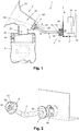
Figure 1 diagrammatically shows a breast pump device according to the invention, comprising an expression kit and a vacuum unit connected to the expression kit through a hose, wherein the expression kit, the hose and connectors as located at both ends of the hose, and a connection part of the vacuum unit are shown in a sectional view, and wherein a vacuum pump, a motor of the vacuum pump, a controller, and a sensor, which are components of the vacuum unit, are represented by blocks; and -
Figure 2 diagrammatically shows a perspective view of the assembly of the hose and the connectors, and the connection part of the vacuum unit, wherein the assembly of the hose and the connectors is shown separately from the connection part of the vacuum unit. -
Figures 1 and 2 relate to abreast pump device 1 according to the invention, comprising anexpression kit 2 and avacuum unit 3 for generating a pressure cycle during which vacuum is alternately created and released. Theexpression kit 2 comprises abreast pump body 20 and amilk receptacle 4 which is connectable to thebreast pump body 20, e.g. by screwing, thereby closing a lower end of thebreast pump body 20. Thevacuum unit 3 is an electric vacuum unit and comprises apump 31, anelectric motor 32 for driving thepump 31, and acontroller 33 for controlling operation of themotor 32. Practical aspects of thevacuum unit 3, such as the mechanical connection of thepump 31 to themotor 32, and the electric connection of themotor 32 to a source of electric power, which may be the mains or a battery, for example, will not be deliberated on here as such aspects are known in the field of breast pump devices and may be conventional in the framework of the invention. - In
figure 1 , thebreast pump device 1 is shown in an assembled condition, in which thevacuum unit 3 is connected to theexpression kit 2 through ahose 5. Such a configuration allows for a remote arrangement of thevacuum unit 3 with respect to theexpression kit 2, so that the size of that part of thebreast pump device 1 which is to be applied to a user's breast can be kept within reasonable limits. At one end, thehose 5 is connected to theexpression kit 2 through asuitable connector 6 arranged at that particular end, which will hereinafter be referred to asexpression kit connector 6. Likewise, at the other end, thehose 5 is connected to thevacuum unit 3 through asuitable connector 7 arranged at that particular end, which will hereinafter be referred to asvacuum unit connector 7. Thebreast pump body 20 of theexpression kit 2 has afirst pressure chamber 21 and asecond pressure chamber 22. Thefirst pressure chamber 21 is configured for receiving theexpression kit connector 6. - It is to be noted that the
breast pump device 1 can comprise twoexpression kits 2 for enabling a user of thebreast pump device 1 to extract milk from two breasts at the same time, in which case theexpression kits 2 can share acommon vacuum unit 3. - The
second pressure chamber 22 comprises a breast-receivingfunnel 23, an aperture acting as amilk outlet 24, and amilk path 25 from the breast-receivingfunnel 23 to themilk outlet 24. The breast-receivingfunnel 23 is thus in fluid communication with themilk outlet 24 through themilk path 25. Optionally, a one-way valve is arranged at themilk outlet 24, for letting breast milk pass from thesecond pressure chamber 22 to themilk receptacle 4. The breast-receivingfunnel 23 can comprise a massage cushion or the like (not shown) for providing a soft and warm feel to the breast and/or imitating a baby's sucking action. In the shown example, thefirst pressure chamber 21 is located at a backside of the breast-receivingfunnel 23. Within the framework of the invention, other locations of thefirst pressure chamber 21 are possible, including a location at themilk receptacle 4 in case there is no valve at themilk outlet 24. - The
first pressure chamber 21 and thesecond pressure chamber 22 are separated at the position of abarrier portion 26 that is located in thebreast pump body 20. Thebarrier portion 26 is designed to function as a milk leakage preventing arrangement at the position of anair outlet 27 of theexpression kit 20 and may be realized as a solid sheet being provided with a number of holes having dimensions in the micrometer range, or as a porous membrane or a labyrinth, for example. Furthermore, at least at the position of thebarrier portion 26, the material of thebreast pump body 20 may have hydrophobic properties. In any case, it is intended for thebarrier portion 26 to serve as an arrangement in thebreast pump device 1 that is air-permeable and liquid-impermeable, at a position associated with the very position where air flows out of theexpression kit 2 in the direction of thevacuum unit 3 during operation of thebreast pump device 1. In that way, it is achieved that thebarrier portion 26 serves for separating thefirst pressure chamber 21 from themilk path 25 in thesecond pressure chamber 22, thereby increasing the level of hygiene of thebreast pump device 1 and preventing liquid from reaching thehose 5 and thevacuum unit 3, while allowing for air communication between thefirst pressure chamber 21 and thesecond pressure chamber 22, at least to such an extent that the breast milk expression functionality of thebreast pump device 1 is not hampered, assuming that thebarrier portion 26 provides a sufficiently low pneumatic restriction to the air flow. For example, a vacuum applied to thefirst pressure chamber 21 also causes vacuum in thesecond pressure chamber 22 since air can pass through thebarrier portion 26, whereas water and/or breast milk in thesecond pressure chamber 22 are blocked. Thereby, thebarrier portion 26 acts as a hygienic shield. Having ahydrophobic barrier portion 26 may further positively influence bacteria-related aspects of thebreast pump device 1, such that bacteria transfer to thehose 5 and thevacuum unit 3 are prevented. - It is possible for the
breast pump body 20 to be equipped with a splash guard (not shown) arranged in thesecond pressure chamber 22 for shielding thebarrier portion 26 from droplets of breast milk. Thereby, such a splash guard can act as a first barrier which avoids that too much breast milk reaches thebarrier portion 26. Droplets of breast milk which reach thebarrier portion 26 anyway can clear off thebarrier portion 26 automatically in case thebarrier portion 26 is hydrophobic. Advantageously, the entirebreast pump body 20 is made of one single material, preferably a clear plastic material having hydrophobic properties, such as polymethylpentene (PMP) or polypropylene (PP). - General operational aspects of the
breast pump device 1 will now be mentioned. In the first place, a user makes sure that theexpression kit 2 and thevacuum unit 3 are properly connected to each other through thehose 5 and theconnectors vacuum unit 3 is activated, the user furthermore needs to take care that themilk receptacle 4 is properly connected to thebreast pump body 20, and that the breast to be subjected to a milk extraction process is properly inserted into the breast-receivingfunnel 23 of thesecond pressure chamber 22. In that situation, a breast-receiving end of thesecond pressure chamber 22 is sealingly closed by the breast, whereas a lower end of thesecond pressure chamber 22 is sealingly closed by themilk receptacle 4. When, starting from that situation, thevacuum unit 3 is activated, a pressure cycle involving generation and release of vacuum is realized in thefirst pressure chamber 21, as a result of which the breast is subjected to forces which serve for simulating a feeding situation, as a result of which milk supply is induced from the breast, and during which it happens that air is sucked in thefirst pressure chamber 21 from thesecond pressure chamber 22 through thebarrier portion 26. A desired pressure profile, i.e. a time-variable pressure, can be applied to the breast taking into account the pneumatic restriction of thebarrier portion 26. The breast milk flows from the breast-receivingfunnel 23 to themilk receptacle 4 through themilk path 25 and themilk outlet 24, under the influence of gravity and/or the pressure generated by thevacuum unit 3. - According to the invention, in view of a practical possibility that despite the use of a milk leakage preventing arrangement comprising a
barrier portion 26 in thebreast pump device 1, it may accidentally happen that a few droplets of milk end up on thebarrier portion 26, have a clogging effect on thebarrier portion 26 and/or eventually pass to the pump side of thebarrier portion 26, measures are taken in order to prevent milk from reaching the inside of thevacuum unit 3. These measures involve a configuration of thecontroller 33 that is aimed at performing a process of monitoring behavior of themotor 32 for driving thepump 31 and stopping operation of themotor 32 as soon as an abnormality is found in the behavior of themotor 32. Within the framework of the invention, many ways exist for performing such a process. In any case, suitable means such as asensor 34 may be used for detecting at least one operational characteristic of themotor 32 and transmitting detected information to thecontroller 33 which is preprogrammed to process the detected information in a suitable manner. In particular, thecontroller 33 is configured to make a comparison between the detected information and an appropriate reference, and to terminate power supply to themotor 32 as soon as the comparison shows that a deviation of the detected information from the reference is larger than an allowable maximum. Naturally, if the motor behavior appears to be within limits of what normally might be expected, there is no need for action aimed at automatically shutting off the motor. Infigure 1 , the interaction between themotor 32, thecontroller 33 and thesensor 34 is diagrammatically indicated by means of dashed lines. - Examples of operational characteristics of the
motor 32 that may be monitored include the electric current drawn by themotor 32 and a rotational speed of themotor 32. A clogging effect of milk on thebarrier portion 26 and or a presence of milk somewhere between thebarrier portion 26 and thevacuum unit 3 may cause themotor 32 to stall, as themotor 32 is only allowed to evacuate a smaller volume of air than the volume that is normally expected. In the art of electric motors, it is a known fact that when a motor stalls, the current drawn by the motor increases significantly. Thus, a possibility existing within the framework of the invention is to detect the current drawn by the motor and to assess whether the current is higher than may be expected and/or increases at a high rate. Also, taking into account the voltage supplied to themotor 32, the current curve can be monitored and compared to a reference that is appropriate in view of the voltage. In such a case, thecontroller 33 is used to switch off themotor 32 when the detected current curve appears to deviate from the reference current curve to a too large extent. - Besides relying on measurements of the current drawn by the
motor 32, it is also possible to detect the rotational speed of the motor. Assuming that the voltage supplied to themotor 32 is kept constant, an increase of the rotational speed indicates that there are abnormalities in the pressure cycle, and thus, information about the rotational speed may be used for stopping themotor 32. For the purpose of detecting the rotational speed of themotor 32, themotor 32 may be equipped with a suitable RPM sensor. - Advantages of automatically terminating operation of the
motor 32 are that it is not necessary to involve the user of thebreast pump device 1 in a process of keeping watch if the device is functioning correctly. Also, as it takes some time for milk drawn through thebarrier portion 26 to travel towards thevacuum unit 3, due to the length of thehose 5, a completely safe process is realized, in which themotor 32 can be stopped in time in order to terminate a sucking effect on the milk. Safety can even be further enhanced by designing at least one of theconnectors respective connector connector vacuum unit 3. In the shown example, bothconnectors milk collector connector breast pump device 1 is equipped with one or more milk collectors, it is not essential for the milk collector(s) to be arranged in at least one of theconnectors - In the shown example, the
expression kit connector 6 comprises anair tube 62 extending from aninside space 63 of theconnector 6 to outside of theconnector 6. Interconnecting thehose 5 and theexpression kit connector 6 involves inserting theair tube 62 in an end of thehose 5. When theconnector 6 is arranged on theexpression kit 2 and thebreast pump device 1 is operated, air that is drawn from the breast-receivingfunnel 23 passes thebarrier portion 26 and enters thehose 5 through theair tube 62 of theconnector 6. As theair tube 62 does not extend all the way to the expression kit side of theconnector 6, a gap is present between thebarrier portion 26 and the entrance of theair tube 62. As a consequence, any milk passing through thebarrier portion 26 falls down inside theconnector 6 under the influence of gravity at the position of the gap. The milk is then retained in themilk collector 61 of thecollector 6, which is located at a lower level than the entrance of theair tube 62. Preferably, theexpression kit connector 6 is at least partially made of transparent material so that the user of thebreast pump device 1 may actually see the milk in case leakage has occurred. - Likewise, the
vacuum unit connector 7 comprises anair tube 72 extending from aninside space 73 of theconnector 7 to outside of theconnector 7. Interconnecting thehose 5 and thevacuum unit connector 7 involves inserting theair tube 72 in an end of thehose 5. When theconnector 7 is arranged on thevacuum unit 3 and thebreast pump device 1 is operated, air is drawn towards thevacuum unit 3 through thehose 5 and theair tube 72. Theair tube 72 does not extend all the way to the vacuum unit side of theconnector 7, so that the air is released from theair tube 72 in theinside space 73 of theconnector 7. In the configuration as shown, theair tube 72 has a central arrangement in theconnector 7, whereas anair inlet 35 of thevacuum unit 3 has a non-central arrangement in anarea 36 of thevacuum unit 31 that is configured to receive theconnector 7, and is located at a higher level than theair tube 72 of theconnector 7 when theconnector 7 is in place in thearea 36 as mentioned. As a consequence of the fact that theair inlet 35 of thevacuum unit 3 is not aligned with theair tube 72 of theconnector 7, but is located at a higher level instead, any milk that may have travelled all the way down to thevacuum unit connector 7 falls down inside theconnector 7 under the influence of gravity as soon as it exits theair tube 72. The milk is then retained in themilk collector 71 of thecollector 7, which is located at a lower level than the exit of theair tube 72. Preferably, thevacuum unit connector 7 is at least partially made of transparent material so that the user of thebreast pump device 1 may actually see the milk in case leakage has occurred. - It follows from the foregoing that, according to the invention, a
breast pump device 1 is realized that is safe and easy to use. Milk leakage from theexpression kit 2 towards thehose 5 and thevacuum unit 3 is prevented by means of thebarrier portion 26 as arranged at the position of theair outlet 27 of theexpression kit 2, through which the air that is drawn from the breast-receivingfunnel 23 towards thevacuum unit 3 under the influence of thepump 31 passes. In case some droplets of milk enter thebarrier portion 26 and have a clogging effect on thebarrier portion 26 as a consequence thereof and/or in case some droplets of milk are drawn through thebarrier portion 26 by an ongoing pumping action, aspects of the behavior of themotor 32 for driving thepump 31 are influenced, and the insight that this happens is used for terminating operation of themotor 32 as soon as a too large deviation of one or more operational characteristics of themotor 32 is found. The process of determining whether themotor 32 should be switched off involves detecting one or more operational characteristics of themotor 32 and processing detected information in thecontroller 33, particularly comparing detected information to an appropriate reference and assessing whether a deviation is found that is larger than a predetermined maximum. Unlike known prior art solutions, there is no need to apply a sensor for detecting the presence of liquid at a suitable position in thebreast pump device 1. - It will be clear to a person skilled in the art that the scope of the invention is not limited to the examples discussed in the foregoing, but that several amendments and modifications thereof are possible without deviating from the scope of the invention as defined in the attached claims. It is intended that the invention be construed as including all such amendments and modifications insofar they come within the scope of the claims or the equivalents thereof. While the invention has been illustrated and described in detail in the figures and the description, such illustration and description are to be considered illustrative or exemplary only, and not restrictive. The invention is not limited to the disclosed embodiments. The drawings are schematic, wherein details that are not required for understanding the invention may have been omitted, and not necessarily to scale.
- Variations to the disclosed embodiments can be understood and effected by a person skilled in the art in practicing the claimed invention, from a study of the figures, the description and the attached claims. In the claims, the word "comprising" does not exclude other steps or elements, and the indefinite article "a" or "an" does not exclude a plurality. Any reference signs in the claims should not be construed as limiting the scope of the invention.
- Elements and aspects discussed for or in relation with a particular embodiment may be suitably combined with elements and aspects of other embodiments, unless explicitly stated otherwise. Thus, the mere fact that certain measures are recited in mutually different dependent claims does not indicate that a combination of these measures cannot be used to advantage.
- The term "comprise" as used in this text will be understood by a person skilled in the art as covering the term "consist of'. Hence, the term "comprise" may in respect of an embodiment mean "consist of", but may in another embodiment mean "contain/include at least the defined species and optionally one or more other species".
Claims (14)
- Breast pump device (1) for extracting breast milk from a human breast, comprising:- an expression kit (2) comprising a breast-receiving funnel (23), a milk outlet (24), an air outlet (27), and a milk leakage preventing arrangement (26) associated with the air outlet (27), constituting a barrier to human breast milk while allowing air to pass,- a vacuum unit (3) comprising an air inlet (35), a pump (31) for sucking air from the breast-receiving funnel (23) of the expression kit (2), through the air outlet (27) of the expression kit (2) and the air inlet (35) of the vacuum unit (3), and an electric motor (32) for driving the pump (31),- a conduit (5) for establishing an air path between the air outlet (27) of the expression kit (2) and the air inlet (35) of the vacuum unit (3), and- a control system (33, 34) for controlling operation of the motor (32) for driving the pump (31), particularly for controlling a supply of electric power to the motor (32), the control system (33, 34) being configured to detect at least one operational characteristic of the motor (32), to make a comparison between the detected at least one operational characteristic and a reference of the at least one operational characteristic throughout operation of the breast pump device (1), and to terminate power supply to the motor (32) when it follows from the comparison that a deviation of the at least one operational characteristic from the reference is larger than a predetermined maximum deviation.
- Breast pump device (1) according to claim 1, wherein the control system (33, 34) is configured to detect at least one of an electric current drawn by the motor (32) and a rotational speed of the motor (32).
- Breast pump device (1) according to claim 1 or 2, wherein the control system (33, 34) is configured to determine an actual value of the reference of the at least one operational characteristic in relation to an actual input voltage of the motor (32).
- Breast pump device (1) according to claim 1 or 2, wherein the control system (33, 34) is configured to use a detected value of the at least one operational characteristic as a reference for a next detected value of the at least one operational characteristic.
- Breast pump device (1) according to claim 1 or 2, wherein the reference involves a curve of the at least one operational characteristic over time, and wherein the control system (33, 34) is configured to determine a curve of the detected at least one operational characteristic over time, to make a comparison of the detected curve and the reference curve, and to terminate power supply to the motor (32) when it follows from the comparison that a deviation of the detected curve from the reference curve is larger than a predetermined maximum deviation.
- Breast pump device (1) according to claim 5, wherein the control system (33, 34) is configured to determine the reference curve of the at least one operational characteristic over time in relation to an input voltage curve of the motor (32) over time.
- Breast pump device (1) according to any of claims 1-6, comprising at least one milk collector (61, 71) for receiving and collecting any milk leaking from the expression kit (2), the milk collector (61, 71) being located beyond the milk leakage preventing arrangement (26) associated with the air outlet (27) of the expression kit (2), as seen from the breast-receiving funnel (23) of the expression kit (2).
- Breast pump device (1) according to claim 7, comprising connectors (6, 7) for arrangement at the respective ends of the conduit (5), the one connector (6) being configured to connect the conduit (5) in an airtight manner to the air outlet (27) of the expression kit (2), and the other connector (7) being configured to connect the conduit (5) in an airtight manner to the air inlet (35) of the vacuum unit (3), wherein at least one of the connectors (6, 7) comprises a room constituting a milk collector (61, 71).
- Breast pump device (1) according to claim 8, wherein the at least one connector (6, 7) comprising the milk collector (61, 71) is designed for having the room of the connector (6, 7) located at a lower level than an area (62, 72) of the connector (6, 7) that is configured to connect the connector (6, 7) to the conduit (5).
- Breast pump device (1) according to claim 8 or 9, wherein the connector (7) that is configured for connecting the conduit (5) in an airtight manner to the air inlet (35) of the vacuum unit (3) is designed to connect to the conduit (5) at a central area (72) thereof, and wherein the air inlet (35) of the vacuum unit (3) is arranged at a higher level than a center of an area (36) of the vacuum unit (3) that is configured to receive the connector (7).
- Breast pump device (1) according to any of claims 8-10, wherein the at least one connector (6, 7) comprising the milk collector (61, 71) is at least partially made of a transparent material.
- Breast pump device (1) according to any of claims 1-11, wherein the milk leakage preventing arrangement (26) associated with the air outlet (27) of the expression kit (2) is hydrophobic and comprises a solid sheet of material, the sheet being provided with holes.
- Breast pump device (1) according to any of claims 1-11, wherein the milk leakage preventing arrangement (26) associated with the air outlet (27) of the expression kit (2) is hydrophobic and comprises a porous membrane.
- Breast pump device (1) according to any of claims 1-11, wherein the milk leakage preventing arrangement (26) associated with the air outlet (27) of the expression kit (1) is hydrophobic and comprises a labyrinth.
Priority Applications (7)
| Application Number | Priority Date | Filing Date | Title |
|---|---|---|---|
| EP17158158.0A EP3366329A1 (en) | 2017-02-27 | 2017-02-27 | Breast pump device |
| PCT/EP2018/054719 WO2018154127A1 (en) | 2017-02-27 | 2018-02-27 | Breast pump device |
| CN201880014101.0A CN110382015B (en) | 2017-02-27 | 2018-02-27 | Sucking pump device |
| EP18707368.9A EP3585454A1 (en) | 2017-02-27 | 2018-02-27 | Breast pump device |
| US16/487,218 US11464890B2 (en) | 2017-02-27 | 2018-02-27 | Breast pump device |
| RU2019130464A RU2759893C2 (en) | 2017-02-27 | 2018-02-27 | Breast pump |
| US17/939,329 US20230059967A1 (en) | 2017-02-27 | 2022-09-07 | Breast pump device |
Applications Claiming Priority (1)
| Application Number | Priority Date | Filing Date | Title |
|---|---|---|---|
| EP17158158.0A EP3366329A1 (en) | 2017-02-27 | 2017-02-27 | Breast pump device |
Publications (1)
| Publication Number | Publication Date |
|---|---|
| EP3366329A1 true EP3366329A1 (en) | 2018-08-29 |
Family
ID=58185420
Family Applications (2)
| Application Number | Title | Priority Date | Filing Date |
|---|---|---|---|
| EP17158158.0A Withdrawn EP3366329A1 (en) | 2017-02-27 | 2017-02-27 | Breast pump device |
| EP18707368.9A Pending EP3585454A1 (en) | 2017-02-27 | 2018-02-27 | Breast pump device |
Family Applications After (1)
| Application Number | Title | Priority Date | Filing Date |
|---|---|---|---|
| EP18707368.9A Pending EP3585454A1 (en) | 2017-02-27 | 2018-02-27 | Breast pump device |
Country Status (5)
| Country | Link |
|---|---|
| US (2) | US11464890B2 (en) |
| EP (2) | EP3366329A1 (en) |
| CN (1) | CN110382015B (en) |
| RU (1) | RU2759893C2 (en) |
| WO (1) | WO2018154127A1 (en) |
Cited By (2)
| Publication number | Priority date | Publication date | Assignee | Title |
|---|---|---|---|---|
| EP3735994A1 (en) * | 2019-05-09 | 2020-11-11 | Koninklijke Philips N.V. | Electric breast pump |
| AT526611B1 (en) * | 2023-04-06 | 2024-05-15 | Mam Babyartikel | Method for operating a breast pump |
Families Citing this family (1)
| Publication number | Priority date | Publication date | Assignee | Title |
|---|---|---|---|---|
| CN115814185A (en) * | 2022-11-17 | 2023-03-21 | 深圳童品荟科技有限公司 | Breast pump |
Citations (8)
| Publication number | Priority date | Publication date | Assignee | Title |
|---|---|---|---|---|
| GB686367A (en) | 1950-07-07 | 1953-01-21 | Mueller Ernst Kg | Pump, especially for mother's milk |
| US4857051A (en) * | 1980-09-05 | 1989-08-15 | Isg/Ag | Breastpump |
| WO2000041745A1 (en) | 1999-01-12 | 2000-07-20 | Elena Taggart Medo | Breast pump with overflow sensor and automatic flush feature |
| US20020072701A1 (en) * | 2000-12-01 | 2002-06-13 | Nuesch Hans Ueli | Breast pump arrangement |
| WO2012037724A1 (en) | 2010-09-21 | 2012-03-29 | Hsiao Yen-Hung | Safety device for electric breast pump |
| WO2015150225A1 (en) | 2014-03-31 | 2015-10-08 | Koninklijke Philips N.V. | Breast pump and expression kit for a breast pump |
| US20160287767A1 (en) * | 2015-04-06 | 2016-10-06 | Medela Holding Ag | Breastmilk expression system with detection, feedback and connectability features |
| WO2016156173A1 (en) * | 2015-04-01 | 2016-10-06 | Koninklijke Philips N.V. | Pump unit for a breast pump |
Family Cites Families (18)
| Publication number | Priority date | Publication date | Assignee | Title |
|---|---|---|---|---|
| DE2949654C2 (en) | 1979-12-11 | 1982-03-18 | Walter 2000 Hamburg Nicolai | Automatic switch-off device for a suction device that works with a suction and a ventilation phase |
| JPH07119868B2 (en) * | 1985-06-20 | 1995-12-20 | オリンパス光学工業株式会社 | Interchangeable lens distance information output device |
| US5071403A (en) * | 1989-11-14 | 1991-12-10 | Isg/Ag | Method and apparatus for protecting the pump of a breast pump from fouling by milk |
| US6379327B2 (en) * | 1995-10-06 | 2002-04-30 | Ellen F. Lundy | Hands-free portable breast pump system |
| DE19747842A1 (en) | 1997-10-30 | 1999-05-06 | Nueesch Logistik | Pump for mother's milk with breast body |
| KR100371618B1 (en) * | 2000-04-19 | 2003-02-11 | 서경득 | A breast pump |
| US20020072791A1 (en) * | 2000-12-07 | 2002-06-13 | Eder Joseph C. | Light-activated multi-point detachment mechanism |
| US8118772B2 (en) * | 2004-10-13 | 2012-02-21 | Stella Dao | Breast pump device with self-contained breast milk reservoir |
| US8070715B2 (en) * | 2007-04-11 | 2011-12-06 | Medela Holding Ag | Method and apparatus for minimum negative pressure control, particularly for breastpump with breastshield pressure control system |
| EP2196230A1 (en) * | 2007-12-21 | 2010-06-16 | Koninklijke Philips Electronics N.V. | Breast pump for expressing milk from a breast |
| CN201375699Y (en) * | 2009-02-15 | 2010-01-06 | 郭永峰 | Piston type breast pump |
| DE102010019041A1 (en) * | 2010-05-03 | 2011-11-03 | Mapa Gmbh | Electric breastmilk pump |
| EP2441481A1 (en) * | 2010-10-15 | 2012-04-18 | Koninklijke Philips Electronics N.V. | A breast pump |
| KR101278265B1 (en) * | 2011-06-24 | 2013-06-24 | 주식회사 클리어뷰 헬스케어 | Breast pumping system |
| CN202366231U (en) | 2011-12-08 | 2012-08-08 | 陈少忠 | Breast pump anti-reflux filter |
| JP6158922B2 (en) * | 2012-09-24 | 2017-07-05 | コーニンクレッカ フィリップス エヌ ヴェKoninklijke Philips N.V. | Milking system and method of use thereof |
| RU2652056C2 (en) * | 2012-09-24 | 2018-04-24 | Конинклейке Филипс Н.В. | Actuator control in breast pump system |
| US9878095B2 (en) * | 2015-06-22 | 2018-01-30 | Medtronic Minimed, Inc. | Occlusion detection techniques for a fluid infusion device having a rotary pump mechanism and multiple sensor contact elements |
-
2017
- 2017-02-27 EP EP17158158.0A patent/EP3366329A1/en not_active Withdrawn
-
2018
- 2018-02-27 CN CN201880014101.0A patent/CN110382015B/en active Active
- 2018-02-27 RU RU2019130464A patent/RU2759893C2/en active
- 2018-02-27 WO PCT/EP2018/054719 patent/WO2018154127A1/en active Application Filing
- 2018-02-27 US US16/487,218 patent/US11464890B2/en active Active
- 2018-02-27 EP EP18707368.9A patent/EP3585454A1/en active Pending
-
2022
- 2022-09-07 US US17/939,329 patent/US20230059967A1/en active Pending
Patent Citations (8)
| Publication number | Priority date | Publication date | Assignee | Title |
|---|---|---|---|---|
| GB686367A (en) | 1950-07-07 | 1953-01-21 | Mueller Ernst Kg | Pump, especially for mother's milk |
| US4857051A (en) * | 1980-09-05 | 1989-08-15 | Isg/Ag | Breastpump |
| WO2000041745A1 (en) | 1999-01-12 | 2000-07-20 | Elena Taggart Medo | Breast pump with overflow sensor and automatic flush feature |
| US20020072701A1 (en) * | 2000-12-01 | 2002-06-13 | Nuesch Hans Ueli | Breast pump arrangement |
| WO2012037724A1 (en) | 2010-09-21 | 2012-03-29 | Hsiao Yen-Hung | Safety device for electric breast pump |
| WO2015150225A1 (en) | 2014-03-31 | 2015-10-08 | Koninklijke Philips N.V. | Breast pump and expression kit for a breast pump |
| WO2016156173A1 (en) * | 2015-04-01 | 2016-10-06 | Koninklijke Philips N.V. | Pump unit for a breast pump |
| US20160287767A1 (en) * | 2015-04-06 | 2016-10-06 | Medela Holding Ag | Breastmilk expression system with detection, feedback and connectability features |
Cited By (3)
| Publication number | Priority date | Publication date | Assignee | Title |
|---|---|---|---|---|
| EP3735994A1 (en) * | 2019-05-09 | 2020-11-11 | Koninklijke Philips N.V. | Electric breast pump |
| AT526611B1 (en) * | 2023-04-06 | 2024-05-15 | Mam Babyartikel | Method for operating a breast pump |
| AT526611A4 (en) * | 2023-04-06 | 2024-05-15 | Mam Babyartikel | Method for operating a breast pump |
Also Published As
| Publication number | Publication date |
|---|---|
| WO2018154127A1 (en) | 2018-08-30 |
| RU2019130464A3 (en) | 2021-04-22 |
| US20230059967A1 (en) | 2023-02-23 |
| CN110382015A (en) | 2019-10-25 |
| US20200016304A1 (en) | 2020-01-16 |
| CN110382015B (en) | 2022-08-30 |
| RU2759893C2 (en) | 2021-11-18 |
| US11464890B2 (en) | 2022-10-11 |
| RU2019130464A (en) | 2021-03-29 |
| EP3585454A1 (en) | 2020-01-01 |
Similar Documents
| Publication | Publication Date | Title |
|---|---|---|
| US20230059967A1 (en) | Breast pump device | |
| US7029454B2 (en) | Milking device | |
| CN107614028B (en) | Pump system | |
| CN103037915B (en) | One time use breastpump assembly | |
| WO2017136974A1 (en) | Elastic glove testing and donning device with sterilization function | |
| JP2019511705A5 (en) | ||
| JP2010523283A (en) | Minimum negative pressure control method and apparatus, especially for breast pumps with breast shield pressure control system | |
| KR20200018492A (en) | Breast milk pump | |
| CN206391264U (en) | A kind of internal medicine stomach cleaning device | |
| CN108289982B (en) | Pump device for double-sided breast pump, double-sided breast pump and operation method | |
| CN104703636B (en) | breast pump system | |
| EP3366331A1 (en) | Breast pump device comprising a volatile component analysis system | |
| EP3558412B1 (en) | Expression kit for a breast pump device | |
| CN217593463U (en) | Milk sucking device | |
| US11717599B2 (en) | Breast shield for a breast pump system | |
| KR101614743B1 (en) | A Breastpump for preventing reverse flow of milk | |
| CN209347741U (en) | Novel horn cover applied to breast pump | |
| CN219681295U (en) | breast pump | |
| RU2769177C9 (en) | Breast pump expression kit | |
| RU2795209C2 (en) | Breast pump | |
| EP3366330A1 (en) | Expression kit for a breast pump device | |
| CN208877433U (en) | A kind of hepatobiliary surgery drainage device | |
| CN116271295A (en) | Breast pump | |
| JP2023536020A (en) | breast pump system | |
| TR2021021796A2 (en) | WEARABLE PERISTALTIC BREAST PUMP |
Legal Events
| Date | Code | Title | Description |
|---|---|---|---|
| PUAI | Public reference made under article 153(3) epc to a published international application that has entered the european phase |
Free format text: ORIGINAL CODE: 0009012 |
|
| AK | Designated contracting states |
Kind code of ref document: A1 Designated state(s): AL AT BE BG CH CY CZ DE DK EE ES FI FR GB GR HR HU IE IS IT LI LT LU LV MC MK MT NL NO PL PT RO RS SE SI SK SM TR |
|
| AX | Request for extension of the european patent |
Extension state: BA ME |
|
| STAA | Information on the status of an ep patent application or granted ep patent |
Free format text: STATUS: THE APPLICATION IS DEEMED TO BE WITHDRAWN |
|
| 18D | Application deemed to be withdrawn |
Effective date: 20190301 |