EP3365041B1 - Physiologisch reaktive blutpumpe für den nachweis und die behandlung von ischämie - Google Patents
Physiologisch reaktive blutpumpe für den nachweis und die behandlung von ischämie Download PDFInfo
- Publication number
- EP3365041B1 EP3365041B1 EP16788908.8A EP16788908A EP3365041B1 EP 3365041 B1 EP3365041 B1 EP 3365041B1 EP 16788908 A EP16788908 A EP 16788908A EP 3365041 B1 EP3365041 B1 EP 3365041B1
- Authority
- EP
- European Patent Office
- Prior art keywords
- pump
- mode
- assist device
- pulsatile
- speed
- Prior art date
- Legal status (The legal status is an assumption and is not a legal conclusion. Google has not performed a legal analysis and makes no representation as to the accuracy of the status listed.)
- Active
Links
Images


Classifications
-
- A—HUMAN NECESSITIES
- A61—MEDICAL OR VETERINARY SCIENCE; HYGIENE
- A61B—DIAGNOSIS; SURGERY; IDENTIFICATION
- A61B5/00—Measuring for diagnostic purposes; Identification of persons
- A61B5/02—Detecting, measuring or recording pulse, heart rate, blood pressure or blood flow; Combined pulse/heart-rate/blood pressure determination; Evaluating a cardiovascular condition not otherwise provided for, e.g. using combinations of techniques provided for in this group with electrocardiography or electroauscultation; Heart catheters for measuring blood pressure
- A61B5/026—Measuring blood flow
- A61B5/029—Measuring or recording blood output from the heart, e.g. minute volume
-
- A—HUMAN NECESSITIES
- A61—MEDICAL OR VETERINARY SCIENCE; HYGIENE
- A61B—DIAGNOSIS; SURGERY; IDENTIFICATION
- A61B5/00—Measuring for diagnostic purposes; Identification of persons
- A61B5/24—Detecting, measuring or recording bioelectric or biomagnetic signals of the body or parts thereof
- A61B5/25—Bioelectric electrodes therefor
- A61B5/279—Bioelectric electrodes therefor specially adapted for particular uses
- A61B5/28—Bioelectric electrodes therefor specially adapted for particular uses for electrocardiography [ECG]
- A61B5/283—Invasive
-
- A—HUMAN NECESSITIES
- A61—MEDICAL OR VETERINARY SCIENCE; HYGIENE
- A61B—DIAGNOSIS; SURGERY; IDENTIFICATION
- A61B5/00—Measuring for diagnostic purposes; Identification of persons
- A61B5/24—Detecting, measuring or recording bioelectric or biomagnetic signals of the body or parts thereof
- A61B5/316—Modalities, i.e. specific diagnostic methods
- A61B5/318—Heart-related electrical modalities, e.g. electrocardiography [ECG]
- A61B5/346—Analysis of electrocardiograms
- A61B5/349—Detecting specific parameters of the electrocardiograph cycle
- A61B5/363—Detecting tachycardia or bradycardia
-
- A—HUMAN NECESSITIES
- A61—MEDICAL OR VETERINARY SCIENCE; HYGIENE
- A61M—DEVICES FOR INTRODUCING MEDIA INTO, OR ONTO, THE BODY; DEVICES FOR TRANSDUCING BODY MEDIA OR FOR TAKING MEDIA FROM THE BODY; DEVICES FOR PRODUCING OR ENDING SLEEP OR STUPOR
- A61M60/00—Blood pumps; Devices for mechanical circulatory actuation; Balloon pumps for circulatory assistance
- A61M60/10—Location thereof with respect to the patient's body
- A61M60/122—Implantable pumps or pumping devices, i.e. the blood being pumped inside the patient's body
- A61M60/126—Implantable pumps or pumping devices, i.e. the blood being pumped inside the patient's body implantable via, into, inside, in line, branching on, or around a blood vessel
- A61M60/148—Implantable pumps or pumping devices, i.e. the blood being pumped inside the patient's body implantable via, into, inside, in line, branching on, or around a blood vessel in line with a blood vessel using resection or like techniques, e.g. permanent endovascular heart assist devices
-
- A—HUMAN NECESSITIES
- A61—MEDICAL OR VETERINARY SCIENCE; HYGIENE
- A61M—DEVICES FOR INTRODUCING MEDIA INTO, OR ONTO, THE BODY; DEVICES FOR TRANSDUCING BODY MEDIA OR FOR TAKING MEDIA FROM THE BODY; DEVICES FOR PRODUCING OR ENDING SLEEP OR STUPOR
- A61M60/00—Blood pumps; Devices for mechanical circulatory actuation; Balloon pumps for circulatory assistance
- A61M60/10—Location thereof with respect to the patient's body
- A61M60/122—Implantable pumps or pumping devices, i.e. the blood being pumped inside the patient's body
- A61M60/165—Implantable pumps or pumping devices, i.e. the blood being pumped inside the patient's body implantable in, on, or around the heart
- A61M60/178—Implantable pumps or pumping devices, i.e. the blood being pumped inside the patient's body implantable in, on, or around the heart drawing blood from a ventricle and returning the blood to the arterial system via a cannula external to the ventricle, e.g. left or right ventricular assist devices
-
- A—HUMAN NECESSITIES
- A61—MEDICAL OR VETERINARY SCIENCE; HYGIENE
- A61M—DEVICES FOR INTRODUCING MEDIA INTO, OR ONTO, THE BODY; DEVICES FOR TRANSDUCING BODY MEDIA OR FOR TAKING MEDIA FROM THE BODY; DEVICES FOR PRODUCING OR ENDING SLEEP OR STUPOR
- A61M60/00—Blood pumps; Devices for mechanical circulatory actuation; Balloon pumps for circulatory assistance
- A61M60/20—Type thereof
- A61M60/205—Non-positive displacement blood pumps
- A61M60/216—Non-positive displacement blood pumps including a rotating member acting on the blood, e.g. impeller
-
- A—HUMAN NECESSITIES
- A61—MEDICAL OR VETERINARY SCIENCE; HYGIENE
- A61M—DEVICES FOR INTRODUCING MEDIA INTO, OR ONTO, THE BODY; DEVICES FOR TRANSDUCING BODY MEDIA OR FOR TAKING MEDIA FROM THE BODY; DEVICES FOR PRODUCING OR ENDING SLEEP OR STUPOR
- A61M60/00—Blood pumps; Devices for mechanical circulatory actuation; Balloon pumps for circulatory assistance
- A61M60/40—Details relating to driving
- A61M60/403—Details relating to driving for non-positive displacement blood pumps
- A61M60/419—Details relating to driving for non-positive displacement blood pumps the force acting on the blood contacting member being permanent magnetic, e.g. from a rotating magnetic coupling between driving and driven magnets
-
- A—HUMAN NECESSITIES
- A61—MEDICAL OR VETERINARY SCIENCE; HYGIENE
- A61M—DEVICES FOR INTRODUCING MEDIA INTO, OR ONTO, THE BODY; DEVICES FOR TRANSDUCING BODY MEDIA OR FOR TAKING MEDIA FROM THE BODY; DEVICES FOR PRODUCING OR ENDING SLEEP OR STUPOR
- A61M60/00—Blood pumps; Devices for mechanical circulatory actuation; Balloon pumps for circulatory assistance
- A61M60/50—Details relating to control
- A61M60/508—Electronic control means, e.g. for feedback regulation
- A61M60/515—Regulation using real-time patient data
-
- A—HUMAN NECESSITIES
- A61—MEDICAL OR VETERINARY SCIENCE; HYGIENE
- A61M—DEVICES FOR INTRODUCING MEDIA INTO, OR ONTO, THE BODY; DEVICES FOR TRANSDUCING BODY MEDIA OR FOR TAKING MEDIA FROM THE BODY; DEVICES FOR PRODUCING OR ENDING SLEEP OR STUPOR
- A61M60/00—Blood pumps; Devices for mechanical circulatory actuation; Balloon pumps for circulatory assistance
- A61M60/50—Details relating to control
- A61M60/508—Electronic control means, e.g. for feedback regulation
- A61M60/538—Regulation using real-time blood pump operational parameter data, e.g. motor current
- A61M60/546—Regulation using real-time blood pump operational parameter data, e.g. motor current of blood flow, e.g. by adapting rotor speed
-
- A—HUMAN NECESSITIES
- A61—MEDICAL OR VETERINARY SCIENCE; HYGIENE
- A61M—DEVICES FOR INTRODUCING MEDIA INTO, OR ONTO, THE BODY; DEVICES FOR TRANSDUCING BODY MEDIA OR FOR TAKING MEDIA FROM THE BODY; DEVICES FOR PRODUCING OR ENDING SLEEP OR STUPOR
- A61M60/00—Blood pumps; Devices for mechanical circulatory actuation; Balloon pumps for circulatory assistance
- A61M60/50—Details relating to control
- A61M60/508—Electronic control means, e.g. for feedback regulation
- A61M60/562—Electronic control means, e.g. for feedback regulation for making blood flow pulsatile in blood pumps that do not intrinsically create pulsatile flow
-
- A—HUMAN NECESSITIES
- A61—MEDICAL OR VETERINARY SCIENCE; HYGIENE
- A61M—DEVICES FOR INTRODUCING MEDIA INTO, OR ONTO, THE BODY; DEVICES FOR TRANSDUCING BODY MEDIA OR FOR TAKING MEDIA FROM THE BODY; DEVICES FOR PRODUCING OR ENDING SLEEP OR STUPOR
- A61M2205/00—General characteristics of the apparatus
- A61M2205/33—Controlling, regulating or measuring
- A61M2205/3303—Using a biosensor
-
- A—HUMAN NECESSITIES
- A61—MEDICAL OR VETERINARY SCIENCE; HYGIENE
- A61M—DEVICES FOR INTRODUCING MEDIA INTO, OR ONTO, THE BODY; DEVICES FOR TRANSDUCING BODY MEDIA OR FOR TAKING MEDIA FROM THE BODY; DEVICES FOR PRODUCING OR ENDING SLEEP OR STUPOR
- A61M2205/00—General characteristics of the apparatus
- A61M2205/33—Controlling, regulating or measuring
- A61M2205/3365—Rotational speed
-
- A—HUMAN NECESSITIES
- A61—MEDICAL OR VETERINARY SCIENCE; HYGIENE
- A61M—DEVICES FOR INTRODUCING MEDIA INTO, OR ONTO, THE BODY; DEVICES FOR TRANSDUCING BODY MEDIA OR FOR TAKING MEDIA FROM THE BODY; DEVICES FOR PRODUCING OR ENDING SLEEP OR STUPOR
- A61M2205/00—General characteristics of the apparatus
- A61M2205/50—General characteristics of the apparatus with microprocessors or computers
-
- A—HUMAN NECESSITIES
- A61—MEDICAL OR VETERINARY SCIENCE; HYGIENE
- A61M—DEVICES FOR INTRODUCING MEDIA INTO, OR ONTO, THE BODY; DEVICES FOR TRANSDUCING BODY MEDIA OR FOR TAKING MEDIA FROM THE BODY; DEVICES FOR PRODUCING OR ENDING SLEEP OR STUPOR
- A61M2230/00—Measuring parameters of the user
- A61M2230/04—Heartbeat characteristics, e.g. ECG, blood pressure modulation
Definitions
- the present invention relates to ventricular assist devices (VADs).
- a VAD is a device which is used to assist the heart of a mammalian subject such as a human patient.
- a typical VAD includes a pump which is implanted in the body of the subject.
- the pump typically has an inlet connected to a source of blood to be circulated, and an outlet connected to an artery.
- the inlet of the pump is connected to the interior of the left ventricle and the outlet of the pump is connected to the aorta, so that the pump operates in parallel with the left ventricle to impel blood into the aorta.
- the pump may be a miniature rotary impeller pump having an impeller disposed in a pump housing and driven in rotation by a small electric motor which may be closely integrated with the pump.
- the motor in turn typically is powered by an implantable power source such as a storage battery with an arrangement for charging the battery from an external power source.
- the VAD may also include a control system which controls operation of the power source so as to drive the impeller at a set rotational speed and thus provide constant pumping action.
- WO 2014/015300 A1 relates to a cardiac assist device with pulse wave analysis.
- VADs can be used to assist the heart of subjects suffering from conditions which impair the pumping ability of the heart. Such assistance can be provided permanently, or while the subject awaits a suitable heart transplant. In other cases, the assistance provided by the VAD allows the heart to heal.
- a VAD desirably may include a rotary pump such as a rotary impeller pump implantable in fluid communication with a ventricle and an artery of a subject to assist blood flow from the ventricle to the artery.
- the VAD most preferably may further include a pump drive circuit and also preferably includes one or more sensors for sensing one or more electrophysiological signals such as subcutaneous ECG signals in the subject and providing sensor signals representing the electrophysiological signals.
- the VAD may also include a signal processing circuit connected to the sensors and the pump drive circuit, the signal processing circuit being operative to detect the sensor signals, and control power supplied to the pump from the pump drive circuit so that the pump runs in a normal sinus rhythm mode with a varying speed synchronized with the cardiac cycle of the subject. As further discussed below, operation in the normal sinus rhythm mode provides improved assistance to the heart.
- the signal processing circuit may also be operative to determine the presence or absence of a reduction in cardiac blood flow such as ischemia or angina, or total blockage of blood to the heart muscle as in myocardial infarction, based on the physiological sensor signals and to control power supplied to the pump from the pump drive circuit so as to operate the pump in a normal sinus rhythm mode in the absence of a reduction in cardiac blood flow and to operate the pump in a modified mode of operation in the presence of a reduction in cardiac blood flow.
- the modified mode may be a pulsatile mode with different operational parameters such as a higher speed as compared to the normal sinus rhythm mode.
- the pump may operate in a non-pulsatile and at constant speed in the event of detecting a more severe ischemia or myocardial infarction.
- the VAD may include an implantable rotary pump 2, incorporating a motor 4.
- rotary pump refers to a pump which incorporates a pumping element mounted for rotation in a housing.
- the pump 2 is a rotary impeller pump having an impeller mounted within the housing, so that the spinning motion of the impeller transfers momentum to the fluid to be pumped.
- the pump 2 and motor 4 are depicted as separate components for clarity of illustration in FIG. 1 , in practice these components can be closely integrated with one another.
- the impeller of the pump 2 may serve as the rotor of the motor 4.
- the motor 4 is a multi-phase brushless direct current, permanent magnet motor arranged to drive the impeller of the pump 2 at a rotational speed prescribed by the motor driver by means of a motor commutation technique such as trapezoidal commutation.
- a motor commutation technique such as trapezoidal commutation.
- the pump 2 can be implanted within the body of a mammalian subject such as a human patient, with the inlet 3 in fluid communication with a ventricle of the heart, most typically the left ventricle, and with the outlet 5 in fluid communication with an artery, most typically the aorta.
- the pump 2 may be arranged for implantation outside of the heart, and the inlet and outlet may include conduits that can be surgically connected to the ventricle and the aorta.
- the pump 2 is arranged so that it may be implanted within the aorta and ventricle.
- Exemplary implantable pumps are described in detail in U.S. Patent Nos. 6,264,635 , 6,234,772 and 7,699,586 ; and U.S. Patent Publication No. 20090112312 .
- the VAD may also include a pump drive circuit 6.
- the pump drive circuit 6 may include an electrical storage battery and a motor driver to control the motor.
- the output of the motor driver may be connected by an output connection, such as a cable 9 to the motor 4 of pump 2, so that the motor driver can drive the motor 4 and thus operate the pump 2.
- the motor driver may typically include semiconductor switching elements which are responsive to control signals applied at a control input 7, so that the current supplied to motor 4 can be controlled.
- pump drive circuit 6 may be mountable outside of the patient's body B and may be connected to the motor 4 by conductors which penetrate the skin of the patient. In other arrangements, the pump drive circuit 6 may be implanted within the body and may be connected to an external power source by an inductive coupling or skin-penetrating conductors.
- Pump 2 optionally may be equipped with a condition sensor 8 such as a speed sensor.
- the condition sensor may include a back EMF detector operative to detect voltage or current in the stator coils of motor 4 as a measure of motor speed or load.
- the VAD may also include a signal processing circuit 23.
- the signal processing circuit 23 may include an implantable internal module 12 and an external module 18 arranged for mounting outside of the subject's body B. Modules 18 and 6 may also be implanted with the patient's body.
- the signal processing circuit 23 may be connected to the control input 7 of pump drive circuit 6.
- modules 12 and 18 are connected to one another by a suitable signal transmitting arrangement such as radio frequency telemetry transmitting and receiving units 16 so that signals and data can be interchanged between the modules.
- Modules 12 and 18 may include conventional data processing elements such as one or more microprocessors 15 and one or more memory elements 13 arranged to perform the algorithms discussed below. The distribution of hardware elements and software functions between these modules can be varied over a wide range.
- the internal module 12 acts essentially as a conduit for data and signals.
- all of the hardware and software required to perform the algorithms resides in the internal module 12, and the external module is omitted.
- the power required to operate the electronic circuitry of the internal module 12 typically is about 3 orders of magnitude less than the power required to drive motor 4.
- the internal module 12 may be connected to receive power from the alternating current supplied by the pump drive circuit 6 to motor 4. This arrangement is particularly useful where the internal module 12 is physically located at the pump 2. Where the internal module of the signal processing circuit 23 is physically located at the pump 2, it may be desirable to provide magnetic shielding between the coils of the pump motor 4 and the circuitry of the internal module 12. Alternatively, where the internal module 12 is located away from the pump 2, then the signal processing circuitry 23 can receive power from an internal battery such as a primary battery or rechargeable battery.
- the VAD further includes sensors 10 which may be connected to the internal module 12 of the signal processing circuit 23.
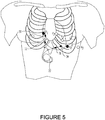
- the sensors include subcutaneous electrodes implanted at pre-cordial (or chest) locations similar to a 12 lead ECG cardiac monitor such as designations VI through V5. Recordings from these electrodes could be of unipolar configuration with a far field remote anode 41 ( FIG. 2 ), such as the conductive titanium case of the implanted electronics 22 connected to receive electrical signals from the subcutaneous pre-cordial electrodes 30, 32, 34, 36. The electrical recordings could also be bipolar with respect pairs of electrodes.
- the subcutaneous pre-cordial electrodes 30, 32, 34, and 36 are disposed at appropriate locations near the heart of the subject.
- the sensors 10 optionally also include one or more physiological condition sensors 43.
- the physiological condition sensors 43 can be used to sense and transmit any type of physiological parameter, including but not limited to oxygen concentration, pressure within a vessel or chamber, and temperature.
- Sensors 10 optionally may also include one or more further sensors 45 arranged to provide a signal representing a parameter related to cardiac demand.
- the further sensors 45 may include one or more accelerometers arranged to provide signals representing movement of the patient's body B. There may be a positive correlation between the amount of movement and cardiac demand.
- the various sensors are connected to the internal module 12 of the signal processing circuit 23 through appropriate signal conditioning elements such as an analog to digital converter 47 and buffer memory 49.
- Signal processing circuit 23 may be configured with functionality to receive, analyze and process signals received from sensors as they relate to the physiological condition of the patient. Some of this functionality may include processing signals from sensors 10 to determine the phase of the patient's cardiac cycle; sensing the patient's intrinsic heart rate; determining the patient's metabolic demand; and detecting a reduction of blood flow to the heart during conditions of ischemia or during more significant reduction as with myocardial infarction, and in response to those signals, may set the mode of operation and speed of the pump 2 accordingly. The signal processing circuit 23 may also control the frequency of the motor drive signal to the pump 2.
- Signal processing circuit 23 may be specifically configured to repeatedly execute an algorithm as shown in simplified form in FIG. 3 .
- a processor 15 may execute a beat detection routine using signals acquired from the subcutaneous electrodes 30, 32, 34 and 36.
- Beat detection algorithms based on pre-cordial electrode signals are well known in the art and are commonly employed in devices such as 12 lead ECG cardiac monitors. Any detection circuit or algorithm routine which is effective to discriminate a normal sinus beat versus an ectopic (non-sinus) beat can be employed.
- the algorithm branches depending on the results of the individual beat detection. If the detection has determined by processor 15 that the subject's heart is a non-sinus (or an ectopic beat), the algorithm ignores the beat 112 and returns to the beat detection algorithm 102. If the beat determination algorithm 104 as determined by the processor 15 that the beat is of normal sinus origin, then the algorithm moves on to the ST segment measurement function 106 which would be performed by processor 15. Once the ST segment amplitude is measured 106 by the processor 15, the algorithm determines whether there is a ST segment level deviation sufficiently greater than a specified amplitude (positive and/or negative) 116. This ST segment measurement by processor 15 may also be determined by calculating a moving average of multiple detected normal sinus beats. The moving average data may be stored in memory 13.
- the algorithm determines that an ischemic reduction of blood flow to the cardiac muscle has occurred, the VAD pump drive 6 is instructed to operate in an ischemia mode 114 as prescribed (e.g., programmed) by the physician and controlled by processor module 18.
- the ischemia operational conditions may be an increase in the pulsatile speed while still synchronized to the natural heart beat.
- the algorithm may determine that the cardiac muscle is in a myocardial infarction condition.
- the VAD pump drive 6 is instructed by the processor module 18 to operate in an myocardial infarction mode 119 as prescribed (e.g., programmed) by the physician.
- the myocardial infarction mode may be to switch the pump drive 6 to a constant speed mode in order to increase the cardiac output.
- the VAD may continue to operate in the normal sinus rhythm mode 118.
- the signal processing circuit 23 actuates pump drive circuit 6 to vary the speed of the pump 2 between a minimum speed and a maximum speed, as depicted by curve 108 ( FIG. 4B ).
- the pattern of variation in the speed of the pump 2 is synchronized with the intrinsic rhythm of the patient's heart as shown by the subcutaneous ECG signals so that the variation in speed of the pump 2 has a substantially fixed phase relationship to the intrinsic rhythm of the heart.
- the pump 2 operates at maximum speed during ventricular systole, when the ventricles contract to expel blood.
- 4A is a schematic depiction showing a conventional external electrocardiogram waveform, which represents a composite of the electrical signals in the entire heart.
- the actual subcutaneous ECG signals appearing on electrodes 30, 32, 34 and 36 FIG. 5
- the recorded data may be stored in memory 13 for future analysis against suspected non-sinus beats.
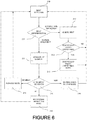
- signal processing circuit 23 repeatedly executes an algorithm as shown in simplified form in FIG. 6 .
- a processor may execute a beat detection routine using signals acquired from the subcutaneous electrodes 30, 32, 34 and 36. Beat detection based on pre-cordial electrode signals are well known in the art and are commonly employed in devices such as 12 lead ECG cardiac monitors. Any detection circuit or algorithm routine which is effective to detect a normal sinus beat versus an ectopic (non-sinus) beat can be programmed into the processor 15.
- the algorithm branches depending on the results of the individual beat detection. If the detection has determined that the subject's heart is a non-sinus beat, the algorithm ignores the beat 212 and continues with the ventricular tachy-arrhythmia rhythm detection algorithm 213. If the ventricular tachy-arrhythmia rhythm detection algorithm determines that there is no ventricular tachy-arrhythmia rhythm present, and is a non-sustained condition, then the algorithm returns to the beat detection 202. If the ventricular tachy-arrhythmia detection 213 determines that a ventricular tachy arrhythmia is present, the algorithm enters a ventricular tachy-arrhythmia mode 215.
- the beat detection algorithm 204 determines that the beat is of normal sinus origin, then the algorithm moves on to the ST segment measurement function 206. Once the ST segment amplitude is measured, the algorithm determines whether there is a ST segment level deviation sufficiently greater than a specified amplitude (positive and/or negative) 216 as calculated by the processor 15. This ST segment measurement may also be determined by calculating a moving average of multiple detected normal sinus beats. The moving average data may be stored in memory 13. If the ST segment measurement exceeds a specified threshold for an ischemic condition, then the algorithm determines that an ischemic reduction of blood flow to the cardiac muscle has occurred, the VAD is instructed to operate in an ischemia mode 214 as prescribed (e.g., programmed) by the physician and controlled by processor module 18.
- an ischemia mode 214 as prescribed (e.g., programmed) by the physician and controlled by processor module 18.
- the algorithm may determine that the cardiac muscle is in a myocardial infarction condition. If the ST segment measurement exceeds a threshold indicative of a myocardial infarction, the VAD pump drive 6 is instructed by the processor module 18 to operate in an myocardial infarction mode 219 as prescribed (e.g., programmed) by the physician. For this condition the myocardial infarction mode may be to switch the pump drive 6 to a constant speed mode in order to increase the cardiac output. If there is no reduction in cardiac blood flow detected, then the VAD operates in the normal sinus rhythm mode 218.
- the myocardial infarction mode may be to switch the pump drive 6 to a constant speed mode in order to increase the cardiac output. If there is no reduction in cardiac blood flow detected, then the VAD operates in the normal sinus rhythm mode 218.
- the signal processing circuit 23 actuates pump drive circuit 6 to vary the speed of the pump 2 varies between a minimum speed and a maximum speed, as depicted by curve 208 ( FIG. 4B ).
- the pattern of variation in the speed of the pump 2 is synchronized with the intrinsic rhythm of the patient's heart as shown by the subcutaneous ECG signals so that the variation in speed of the pump 2 has a substantially fixed phase relationship to the intrinsic rhythm of the heart.
- the pump 2 operates at maximum speed during ventricular systole, when the ventricles contract to expel blood.
- the ECG curve shown in FIG. 4A is a schematic depiction showing a conventional external electrocardiogram waveform, which represents a composite of the electrical signals in the entire heart.
- the actual subcutaneous ECG signals appearing on electrodes 30, 32, 34 and 36 may be separate signals. Each electrode may provide additional electrical vectors (view) of the cardiac contraction as indicated during the QRS of the heart beat.
- the therapeutic modes as identified in Figure 6 may be exemplified within the following table: Table 1: VAD Operational Modes Based on Detected Conditions Normal Sinus Rhythm Mode Tachycardia Arrhythmia Modes Reduced Cardiac Blood Flow Modes VT VF Ischemia Myocardial Infarction Continuous Flow ⁇ Pulsatile - synchronous (co-pulse) ⁇ ⁇ during recovery Pulsatile - synchronous (counter-pulse) Or ⁇ ⁇ at onset Pulsatile - asynchronous ⁇ Increase Modulated Pump Speeds ⁇ ⁇ ⁇ ⁇ Decrease Modulated Pump Speeds Increase Pulse Duty Cycle ⁇ Decrease Pulse Duty Cycle
- the response by the VAD could be an increase in the modulated pump speed to increase the over cardiac output.
- the therapy mode could change during the detected onset of the infarction and recovery between co-pulsation and counter-pulsation methods of providing pulsatility.
- the counter-pulsation method which increases the speed during diastole reduces the cardiac load variation whereas the co-pulsation method increases the pulse pressure.
- the VAD can alternate between the two methods during the onset and post infarction recovery.
- the therapeutic mode for ventricular fibrillation would be a continuous flow mode with an increase pump speed, since there is no cardiac pulse.
- the therapeutic mode for ventricular tachycardia could impact the pump speed and/or duty cycle, providing an asynchronous pulsatile output.
- the pump 2 desirably reaches maximum speed at a time close to the timing of the R-wave.
- the signal processing circuit 23 can use various features of the subcutaneous ECG signals as the basis for synchronization.
- An ECG signal of the left ventricle using subcutaneous electrodes 34 or 36 ( FIG. 5 ) provides the timing of the ventricular depolarization.
- the signal processing circuit 23 can simply actuate pump drive circuit 6 to increase the speed of pump 2, each time the left ventricle signal indicates beginning of ventricular depolarization, e.g., at the beginning of the R-wave.
- the mechanical components of pump 2 have inertia and require a finite time to accelerate from minimum speed to maximum speed. This time is referred to herein as the slew time T S ( FIG. 4B ).
- the signal processing circuit 23 may actuate the pump drive circuit 6 to progressively increase speed of the pump 2 over a period equal to T S .
- the signal processing circuit 23 can time the beginning of this period T R from the R-wave of the preceding cardiac cycle.
- the cycle time T C of the cardiac cycle is simply the inverse of the heart rate.
- the signal processing circuit 23 can measure the synchronization achieved during each cardiac cycle and advance or retard the initiation of pump acceleration accordingly. For example, if T R was too short in the preceding cycle, so that the pump 2 reached full speed before the R-wave, the signal processing circuit 23 can increase T R for the next cycle.
- the signal processing circuit 23 can act as a phase-locked loop holding the pump speed waveform in synchronization with the intrinsic cardiac cycle of the patient.
- the cyclic variation of pump speed has a fixed phase relationship to the R-wave.
- the measurement of synchronization can be a moving average representing the last few cardiac cycles.
- T D may be selected to equal the P-wave to R-wave interval minus T S .
- T S may be equal to the P-wave to R-wave interval, in which case T D may be zero.
- the cyclic variation of pump speed has a fixed phase relationship to the P-wave.
- Synchronizing the VAD with the patient's intrinsic depolarization will allow the pump 2 to operate when it is most advantageous to do so. Cardiac output is greatest during contraction of the atria and ventricles. In a weak or diseased heart, contraction of the chambers, and particularly the left ventricle is when assistance from a VAD is most critical. Therefore timing of the pump 2 with ventricular contraction will provide the optimal assistance to the patient and maximize the therapeutic effect of the VAD. Moreover, operation in a pulsatile mode synchronized to the subject's cardiac cycle can improve efficiency and thus conserve power.
- the synchronization of the pump 2 can be triggered by the actual occurrence of an electrophysiological signal, it is also possible to program the signal processing circuit 23 to anticipate the impending occurrence of a particular subcutaneous ECG waveform. For example, it is well known that each phase of the cardiac cycle should last for approximately the same duration of time in healthy patients.
- the processor could be programmed by methods known in the art to measure and store historical patient data in a memory 13. This memory 13 could be located anywhere within the circuitry of the VAD, or externally.
- the data would consist of how long each phase of the cardiac cycle lasts in a given patient in a predetermined time. Measurements taken and stored over time can be used to determine through any mathematic or statistical means known, when the next phase of the cardiac cycle should begin in a given patient. This method would allow the processor 15 to instruct the pump drive circuit 6 when to accelerate the pump 2, based on an anticipated subcutaneous ECG waveform. Because atrial and ventricular systole is signaled by the beginning of the P-wave and R-wave respectively, the historical analysis of these phases of the cardiac cycle could be used to predict the onset of systole.
- the signal processing circuit 23 will receive subcutaneous ECG waveform signal information from a patient with left sided heart failure. The signal processing circuit 23 will analyze the signal information and determine when an R-wave is occurring or is about to occur. Upon detecting the occurrence or impending occurrence of the complex, the signal processing circuit 23 will instruct the motor 4, through the pump drive circuit 6, to operate in order to drive the pump 2 in synchronism with the patient's own ventricular systole.
- the signal processing circuit 23 can set the duration D I ( FIG. 4B ) of pump operation at maximum speed during each cardiac cycle based on the historical timing of the patient's R-waves.
- D I can be set as a fixed proportion of the cardiac cycle time T C .
- the signal processing circuit 23 is arranged so that D I , or the routine used to set D I , can be selected by the physician.
- D I is selected so that the pump 2 operates at maximum speed during most or all of ventricular systole.
- the maximum speed of the pump 2 or the D I can be fixed values, or can be set by the signal processing circuit 23 depending on sensed data indicating the current status of the patient.
- the maximum speed may increase with the heart rate as determined by the subcutaneous ECG signals from the electrodes, or as determined based on readings from physiological condition sensor 43 ( FIG. 2 ), cardiac demand parameter sensor 45 or some combination of these.
- the maximum speed may vary depending on whether the patient is sleeping, awake, and/or exercising.
- the minimum speed typically is non-zero speed, so that the pump 2 runs continually but speeds up and slows down during each cycle.
- some rotary impeller pumps utilize hydrodynamic bearings to maintain a pump rotor out of contact with a surrounding pump housing, so that the pump operates with zero wear on the rotor and housing. These hydrodynamic bearings become ineffective when the rotor speed falls below a minimum pump operating speed.
- the minimum speed set by the signal processing circuit 23 desirably is set at or above the minimum pump operating speed. The minimum speed can also vary depending on sensed data.
- Curve 108 depicts the speed variation as a progressive ramp-up from minimum to maximum, followed by operation at maximum, followed by ramp-down to minimum and operation at minimum.
- the pattern of speed variation can be more complex, with the speed continuously varying during the entire cycle.
- the pattern of speed variation is synchronized with the patient's intrinsic cardiac cycle in the manner described above.
- the VAD continues to operate in the normal sinus rhythm mode described above while the signal processing circuit 23 continuously executes beat detection 102 ( FIG. 3 ). So long as the patient remains in normal sinus rhythm, the normal sinus rhythm mode 118 operation continues. However, if an ischemia condition is detected, the program passes to step 114, where the signal processing circuit 23 actuates pump drive circuit 6 to operate the pump 2 in a mode referred to herein as the ischemia mode 112.
- the ischemia mode 114 is a constant-speed mode in which the pump 2 runs at a constant speed and the pump speed does not vary during the cardiac cycle.
- signal processing circuit 23 actuates the pump drive circuit 6 to supply power at a constant frequency to the motor 4 of pump 2, so that the pump 2 operates at a constant speed.
- This speed desirably is less than the maximum speed used during pulsatile operation.
- the signal processing circuit 23 optionally can alter the constant speed depending on conditions detected by the physiologic sensor 43.
- the ischemia mode 114 or the myocardial infarction mode 119 may be a pulsatile mode in which variation of the pump speed is synchronized to the sinus beats.
- the signal processing circuit 23 may include an algorithm to select either a pulsed mode (synchronous or asynchronous) or constant speed mode in response to detecting an ischemia condition or myocardial infarction condition and depending on conditions such as metabolic demand.
- the signal processing circuit 23 While the VAD is in ischemia mode 114, the signal processing circuit 23 continually executes the beat detection routine 102 and the ST segment measurement routine 106. If routine 106 detects a return to normal sinus rhythm, indicating that the ischemia condition has passed, the normal sinus rhythm mode 118 is restored as the pump drive 6 is instructed by the processor module 18. With a long term implant like a VAD, the normal sinus rhythm subcutaneous ECG data would be stored in memory 15 and may be updated on a continuous basis to reflect subtle changes to the baseline waveform and rhythm. This ongoing update of the normal sinus rhythm waveform would be performed by processor 13 and the updated waveforms stored in memory 15.
- the ischemia detection and myocardial infarction detection, and the response discussed above can be applied in VADs having pumps other than rotary pumps.
Landscapes
- Health & Medical Sciences (AREA)
- Heart & Thoracic Surgery (AREA)
- Engineering & Computer Science (AREA)
- Life Sciences & Earth Sciences (AREA)
- Cardiology (AREA)
- General Health & Medical Sciences (AREA)
- Animal Behavior & Ethology (AREA)
- Veterinary Medicine (AREA)
- Public Health (AREA)
- Biomedical Technology (AREA)
- Hematology (AREA)
- Mechanical Engineering (AREA)
- Anesthesiology (AREA)
- Medical Informatics (AREA)
- Molecular Biology (AREA)
- Surgery (AREA)
- Physics & Mathematics (AREA)
- Pathology (AREA)
- Biophysics (AREA)
- Vascular Medicine (AREA)
- Physiology (AREA)
- External Artificial Organs (AREA)
Claims (15)
- Ventrikuläre Unterstützungsvorrichtung, die Folgendes umfasst:eine Rotationspumpe (2), die konfiguriert ist, um in Fluidverbindung mit einem Herz und einem systemischen Kreislauf eines Subjekts implantierbar zu sein, um den Blutfluss von dem Herz zu dem systemischen Kreislauf zu unterstützen;eine Pumpenantriebsschaltung (6) zum Anlegen von Leistung an die Pumpe; eine Pumpenantriebsschaltung, um die Drehzahl der Pumpe zu steuern;einen oder mehrere Sensoren (10) zum Feststellen eines oder mehrerer Elektrogrammsignale bei einem Patienten; undeine Signalverarbeitungsschaltung (23) in Verbindung mit den Sensoren und der Pumpenantriebsschaltung, wobei die Signalverarbeitungsschaltung betriebsfähig ist, um die subkutanen EKG-Signale zu empfangen, wobei die Signalverarbeitungsschaltung betriebsfähig ist, um das Vorhandensein oder das Nichtvorhandensein einer Verringerung des Herzblutflusses oder einen ischämischen Zustand oder einen Myokardinfarktzustand basierend auf subkutanen präkordialen Elektrodensignalen zu bestimmen, und, um Leistung, die von der Pumpenantriebsschaltung an die Pumpe zugeführt wird zu steuern, um die Drehzahl der Pumpe zu steuern und die Pumpe in einem normalen Sinusrhythmusmodus bei dem Nichtvorhandensein eines ischämischen Zustands oder eines Myokardinfarktzustands zu betreiben, und um die Pumpe in wenigstens einem modifizierten Betriebsmodus bei dem Vorhandensein eines ischämischen Zustands oder eines Myokardinfarktzustands zu betreiben,wobei die Schaltung betriebsfähig ist, um einen ischämischen Zustand zu erfassen, und der wenigstens eine modifizierte Betriebsmodus wenigstens einen Ischämiemodus beinhaltet, der sich von dem normalen Sinusrhythmusmodus unterscheidet, undwobei der wenigstens eine Ischämiemodus einen pulsatilen Modus beinhaltet, der sich von dem normalen Sinusrhythmusmodus unterscheidet.
- Ventrikuläre Unterstützungsvorrichtung nach Anspruch 1, wobei die Pumpe eine rotodynamische Pumpe ist.
- Ventrikuläre Unterstützungsvorrichtung nach Anspruch 1, wobei die Signalverarbeitungsschaltung betriebsfähig ist, um die sich ändernde Drehzahl als Reaktion auf einen Zustand des Subjekts einzustellen, insbesondere wobei die Signalverarbeitungsschaltung die sich ändernde Drehzahl gemäß elektrophysiologischen Signalen, die durch die Schaltung von den Sensoren empfangen werden, einstellt.
- Ventrikuläre Unterstützungsvorrichtung nach Anspruch 1, in der die Signalverarbeitungsschaltung betriebsfähig ist, um die Leistung, die der Pumpe zugeführt wird zu steuern, sodass die variierende Drehzahl eine im Wesentlichen feste Phasenbeziehung mit der P-Welle des Herzzyklus des Subjekts aufweist, oder in der die Signalverarbeitungsschaltung betriebsfähig ist, um die Leistung, die der Pumpe zugeführt wird zu steuern, sodass die variierende Drehzahl eine im Wesentlichen feste Phasenbeziehung mit der R-Welle des Herzzyklus des Subjekts aufweist.
- Ventrikuläre Unterstützungsvorrichtung nach Anspruch 1, wobei die elektrophysiologischen Signale subkutane EKG-Wellenformen beinhalten.
- Ventrikuläre Unterstützungsvorrichtung nach Anspruch 5, wobei die subkutanen EKG-Wellenformen wenigstens ein unipolares Signal beinhalten, oder wobei die subkutanen EKG-Wellenformen wenigstens ein bipolares Signal von einem Elektrodenpaar beinhalten.
- Ventrikuläre Unterstützungsvorrichtung nach Anspruch 1, wobei der wenigstens eine Ischämiemodus einen nicht-pulsatilen Modus beinhaltet, wobei die Pumpe auf eine nichtpulsatile Weise läuft.
- Ventrikuläre Unterstützungsvorrichtung nach Anspruch 1, wobei der wenigstens eine pulsatile Modus eine Steigerung der Pumpendrehzahl für ein gesteigertes Herzzeitvolumen beinhaltet.
- Ventrikuläre Unterstützungsvorrichtung nach Anspruch 1, wobei der wenigstens eine Ischämiemodus einen pulsatilen Modus beinhaltet, wobei die Pumpe auf eine pulsatile Weise läuft, die nicht mit dem Herzzyklus des Subjekts synchronisiert ist.
- Ventrikuläre Unterstützungsvorrichtung nach Anspruch 1, wobei die Schaltung betriebsfähig ist, um einen Myokardinfarktzustand zu erfassen, und der wenigstens eine modifizierte Betriebsmodus wenigstens einen Myokardinfarktmodus beinhaltet, der sich von dem normalen Sinusrhythmusmodus unterscheidet.
- Ventrikuläre Unterstützungsvorrichtung nach Anspruch 10, wobei der wenigstens eine Myokardinfarktmodus einen nicht-pulsatilen Modus beinhaltet, wobei die Pumpe auf eine nichtpulsatile Weise läuft, oder wobei der wenigstens eine Myokardinfarktmodus einen anderen pulsatilen Modus als den normalen Sinusrhythmusmodus beinhaltet.
- Ventrikuläre Unterstützungsvorrichtung nach Anspruch 10, wobei der wenigstens eine Myokardinfarktmodus einen pulsatilen Modus beinhaltet, wobei die Pumpe auf eine pulsatile Weise läuft, die nicht mit dem Herzzyklus des Subjekts synchronisiert ist, insbesondere wobei der wenigstens eine pulsatile Modus eine Steigerung der Pumpendrehzahl für ein gesteigertes Herzzeitvolumen beinhaltet.
- Ventrikuläre Unterstützungsvorrichtung nach Anspruch 1, wobei der wenigstens eine modifizierte Modus einen nicht pulsatilen Modus beinhaltet und wobei die Signalverarbeitungsschaltung über den Motortreiber betriebsfähig ist, um die Leistung, die der Pumpe zugeführt wird zu steuern, sodass die Drehzahl der Pumpe in dem nicht-pulsatilen Modus basierend auf einem Zustand des Subjekts variiert.
- Ventrikuläre Unterstützungsvorrichtung nach Anspruch 1, wobei wenigstens ein modifizierter Modus einen ventrikulären Tachyarrhythmiemodus als Reaktion auf einen erfassten Tachyarrhythmiezustand beinhaltet.
- Ventrikuläre Unterstützungsvorrichtung nach Anspruch 4, wobei die im Wesentlichen feste Phasenbeziehung der variierenden Drehzahl mit der R-Welle des Herzzyklus des Subjekts von einer gleitenden durchschnittlichen Zykluszeit über eine Anzahl von Herzzyklen abhängt.
Applications Claiming Priority (2)
| Application Number | Priority Date | Filing Date | Title |
|---|---|---|---|
| US201562245637P | 2015-10-23 | 2015-10-23 | |
| PCT/US2016/057890 WO2017070331A1 (en) | 2015-10-23 | 2016-10-20 | Physiologically responsive blood pump for ischemia detection and treatment |
Publications (2)
| Publication Number | Publication Date |
|---|---|
| EP3365041A1 EP3365041A1 (de) | 2018-08-29 |
| EP3365041B1 true EP3365041B1 (de) | 2020-09-16 |
Family
ID=57219046
Family Applications (1)
| Application Number | Title | Priority Date | Filing Date |
|---|---|---|---|
| EP16788908.8A Active EP3365041B1 (de) | 2015-10-23 | 2016-10-20 | Physiologisch reaktive blutpumpe für den nachweis und die behandlung von ischämie |
Country Status (4)
| Country | Link |
|---|---|
| US (1) | US10632240B2 (de) |
| EP (1) | EP3365041B1 (de) |
| CN (1) | CN108348667B (de) |
| WO (1) | WO2017070331A1 (de) |
Families Citing this family (13)
| Publication number | Priority date | Publication date | Assignee | Title |
|---|---|---|---|---|
| US9968720B2 (en) * | 2016-04-11 | 2018-05-15 | CorWave SA | Implantable pump system having an undulating membrane |
| DK3287154T3 (da) * | 2016-08-23 | 2019-11-18 | Abiomed Europe Gmbh | Ventrikulær hjælpeindretning |
| WO2018102360A1 (en) | 2016-11-30 | 2018-06-07 | Heartware, Inc. | Patient behavior sensitive controller |
| US10780209B2 (en) * | 2017-03-29 | 2020-09-22 | Tc1 Llc | Adjusting pump protocol based on irregular heart rhythm |
| JP7414529B2 (ja) | 2017-06-07 | 2024-01-16 | シファメド・ホールディングス・エルエルシー | 血管内流体移動デバイス、システム、および使用方法 |
| JP7319266B2 (ja) | 2017-11-13 | 2023-08-01 | シファメド・ホールディングス・エルエルシー | 血管内流体移動デバイス、システム、および使用方法 |
| CN117959583A (zh) | 2018-02-01 | 2024-05-03 | 施菲姆德控股有限责任公司 | 血管内血泵以及使用和制造方法 |
| EP3996797A4 (de) | 2019-07-12 | 2023-08-02 | Shifamed Holdings, LLC | Intravaskuläre blutpumpen und verfahren zur herstellung und verwendung |
| WO2021016372A1 (en) | 2019-07-22 | 2021-01-28 | Shifamed Holdings, Llc | Intravascular blood pumps with struts and methods of use and manufacture |
| US11724089B2 (en) | 2019-09-25 | 2023-08-15 | Shifamed Holdings, Llc | Intravascular blood pump systems and methods of use and control thereof |
| CN110613593B (zh) * | 2019-10-17 | 2021-08-10 | 深圳市安康源科技有限公司 | 基于血压值调整的缺血预适应训练方法及系统 |
| CN114259394B (zh) * | 2021-12-13 | 2024-04-09 | 重庆邮电大学 | 一种具有综合康复训练策略的预适应训练系统 |
| WO2023158493A1 (en) * | 2022-02-16 | 2023-08-24 | Tc1 Llc | Real time heart rate monitoring for close loop control and/or artificial pulse synchronization of implantable ventricular assist devices |
Family Cites Families (15)
| Publication number | Priority date | Publication date | Assignee | Title |
|---|---|---|---|---|
| US6572530B1 (en) * | 1997-12-27 | 2003-06-03 | Jms Co., Ltd. | Blood circulation auxiliary device using continuous blood flow pump and diagnosis device for blood circulation state in organism |
| US6264635B1 (en) | 1998-12-03 | 2001-07-24 | Kriton Medical, Inc. | Active magnetic bearing system for blood pump |
| US6234772B1 (en) | 1999-04-28 | 2001-05-22 | Kriton Medical, Inc. | Rotary blood pump |
| WO2005000091A2 (en) * | 2003-05-28 | 2005-01-06 | Payvar, Saeed | Method and apparatus for detecting ischemia |
| US7699586B2 (en) | 2004-12-03 | 2010-04-20 | Heartware, Inc. | Wide blade, axial flow pump |
| DE102007007198A1 (de) * | 2007-02-09 | 2008-08-14 | Maquet Cardiopulmonary Ag | Verfahren und Vorrichtung zur Überwachung und Optimierung eines durch eine Pumpe bewirkten Blutkreislaufs |
| EP2131888B1 (de) | 2007-02-26 | 2017-04-05 | HeartWare, Inc. | Intravaskuläre ventrikuläre hilfsvorrichtung |
| US8075472B2 (en) * | 2007-05-03 | 2011-12-13 | Leviticus-Cardio Ltd. | Permanent ventricular assist device for treating heart failure |
| US8864644B2 (en) * | 2010-01-19 | 2014-10-21 | Heartware, Inc. | Physiologically responsive VAD |
| CN102553005A (zh) * | 2010-12-29 | 2012-07-11 | 北京工业大学 | 一种用于缺血性心脏病的介入式主动脉血泵及其安装方法 |
| EP2570143B1 (de) | 2011-09-14 | 2014-01-15 | BIOTRONIK SE & Co. KG | Implantierbares kardiales Therapiergerät |
| US20150174307A1 (en) | 2012-07-19 | 2015-06-25 | Regents Of The University Of Minnesota | Cardiac assist device with pulse wave analysis |
| GB201219168D0 (en) | 2012-10-25 | 2012-12-12 | Univ Oslo Hf | Control system for a cardiac assist device |
| US9713663B2 (en) | 2013-04-30 | 2017-07-25 | Tc1 Llc | Cardiac pump with speed adapted for ventricle unloading |
| CN104888292A (zh) * | 2015-06-28 | 2015-09-09 | 董羽婕 | 带有反馈装置的血液流量维持系统 |
-
2016
- 2016-10-20 CN CN201680062045.9A patent/CN108348667B/zh active Active
- 2016-10-20 US US15/298,569 patent/US10632240B2/en not_active Expired - Fee Related
- 2016-10-20 EP EP16788908.8A patent/EP3365041B1/de active Active
- 2016-10-20 WO PCT/US2016/057890 patent/WO2017070331A1/en active Application Filing
Non-Patent Citations (1)
| Title |
|---|
| None * |
Also Published As
| Publication number | Publication date |
|---|---|
| EP3365041A1 (de) | 2018-08-29 |
| CN108348667B (zh) | 2020-10-02 |
| US10632240B2 (en) | 2020-04-28 |
| US20170112985A1 (en) | 2017-04-27 |
| CN108348667A (zh) | 2018-07-31 |
| WO2017070331A1 (en) | 2017-04-27 |
Similar Documents
| Publication | Publication Date | Title |
|---|---|---|
| EP3365041B1 (de) | Physiologisch reaktive blutpumpe für den nachweis und die behandlung von ischämie | |
| US10342907B2 (en) | Physiologically responsive VAD | |
| EP3261713B1 (de) | Blutpumpe zur behandlung von bradykardie | |
| EP3287155B1 (de) | Blutpumpe | |
| US9566442B2 (en) | Systems and methods for using pulmonary artery pressure from an implantable sensor to detect mitral regurgitation and optimize pacing delays | |
| US11524165B2 (en) | Blood pump with capability of electrocardiogram (EKG) monitoring, defibrillation and pacing | |
| US10806839B2 (en) | Physiologically responsive VAD for cardiac events | |
| EP3352809B1 (de) | Blutpumpe zur erkennung und behandlung von ischämie |
Legal Events
| Date | Code | Title | Description |
|---|---|---|---|
| STAA | Information on the status of an ep patent application or granted ep patent |
Free format text: STATUS: UNKNOWN |
|
| STAA | Information on the status of an ep patent application or granted ep patent |
Free format text: STATUS: THE INTERNATIONAL PUBLICATION HAS BEEN MADE |
|
| PUAI | Public reference made under article 153(3) epc to a published international application that has entered the european phase |
Free format text: ORIGINAL CODE: 0009012 |
|
| STAA | Information on the status of an ep patent application or granted ep patent |
Free format text: STATUS: REQUEST FOR EXAMINATION WAS MADE |
|
| 17P | Request for examination filed |
Effective date: 20180523 |
|
| AK | Designated contracting states |
Kind code of ref document: A1 Designated state(s): AL AT BE BG CH CY CZ DE DK EE ES FI FR GB GR HR HU IE IS IT LI LT LU LV MC MK MT NL NO PL PT RO RS SE SI SK SM TR |
|
| AX | Request for extension of the european patent |
Extension state: BA ME |
|
| DAV | Request for validation of the european patent (deleted) | ||
| DAX | Request for extension of the european patent (deleted) | ||
| GRAP | Despatch of communication of intention to grant a patent |
Free format text: ORIGINAL CODE: EPIDOSNIGR1 |
|
| STAA | Information on the status of an ep patent application or granted ep patent |
Free format text: STATUS: GRANT OF PATENT IS INTENDED |
|
| INTG | Intention to grant announced |
Effective date: 20200710 |
|
| GRAS | Grant fee paid |
Free format text: ORIGINAL CODE: EPIDOSNIGR3 |
|
| GRAA | (expected) grant |
Free format text: ORIGINAL CODE: 0009210 |
|
| STAA | Information on the status of an ep patent application or granted ep patent |
Free format text: STATUS: THE PATENT HAS BEEN GRANTED |
|
| AK | Designated contracting states |
Kind code of ref document: B1 Designated state(s): AL AT BE BG CH CY CZ DE DK EE ES FI FR GB GR HR HU IE IS IT LI LT LU LV MC MK MT NL NO PL PT RO RS SE SI SK SM TR |
|
| REG | Reference to a national code |
Ref country code: GB Ref legal event code: FG4D |
|
| REG | Reference to a national code |
Ref country code: CH Ref legal event code: EP |
|
| REG | Reference to a national code |
Ref country code: DE Ref legal event code: R096 Ref document number: 602016044180 Country of ref document: DE |
|
| REG | Reference to a national code |
Ref country code: IE Ref legal event code: FG4D |
|
| REG | Reference to a national code |
Ref country code: AT Ref legal event code: REF Ref document number: 1313567 Country of ref document: AT Kind code of ref document: T Effective date: 20201015 |
|
| REG | Reference to a national code |
Ref country code: DE Ref legal event code: R079 Ref document number: 602016044180 Country of ref document: DE Free format text: PREVIOUS MAIN CLASS: A61M0001100000 Ipc: A61M0060000000 |
|
| PG25 | Lapsed in a contracting state [announced via postgrant information from national office to epo] |
Ref country code: FI Free format text: LAPSE BECAUSE OF FAILURE TO SUBMIT A TRANSLATION OF THE DESCRIPTION OR TO PAY THE FEE WITHIN THE PRESCRIBED TIME-LIMIT Effective date: 20200916 Ref country code: GR Free format text: LAPSE BECAUSE OF FAILURE TO SUBMIT A TRANSLATION OF THE DESCRIPTION OR TO PAY THE FEE WITHIN THE PRESCRIBED TIME-LIMIT Effective date: 20201217 Ref country code: NO Free format text: LAPSE BECAUSE OF FAILURE TO SUBMIT A TRANSLATION OF THE DESCRIPTION OR TO PAY THE FEE WITHIN THE PRESCRIBED TIME-LIMIT Effective date: 20201216 Ref country code: BG Free format text: LAPSE BECAUSE OF FAILURE TO SUBMIT A TRANSLATION OF THE DESCRIPTION OR TO PAY THE FEE WITHIN THE PRESCRIBED TIME-LIMIT Effective date: 20201216 Ref country code: SE Free format text: LAPSE BECAUSE OF FAILURE TO SUBMIT A TRANSLATION OF THE DESCRIPTION OR TO PAY THE FEE WITHIN THE PRESCRIBED TIME-LIMIT Effective date: 20200916 Ref country code: HR Free format text: LAPSE BECAUSE OF FAILURE TO SUBMIT A TRANSLATION OF THE DESCRIPTION OR TO PAY THE FEE WITHIN THE PRESCRIBED TIME-LIMIT Effective date: 20200916 |
|
| REG | Reference to a national code |
Ref country code: AT Ref legal event code: MK05 Ref document number: 1313567 Country of ref document: AT Kind code of ref document: T Effective date: 20200916 |
|
| REG | Reference to a national code |
Ref country code: NL Ref legal event code: MP Effective date: 20200916 |
|
| PG25 | Lapsed in a contracting state [announced via postgrant information from national office to epo] |
Ref country code: RS Free format text: LAPSE BECAUSE OF FAILURE TO SUBMIT A TRANSLATION OF THE DESCRIPTION OR TO PAY THE FEE WITHIN THE PRESCRIBED TIME-LIMIT Effective date: 20200916 Ref country code: LV Free format text: LAPSE BECAUSE OF FAILURE TO SUBMIT A TRANSLATION OF THE DESCRIPTION OR TO PAY THE FEE WITHIN THE PRESCRIBED TIME-LIMIT Effective date: 20200916 |
|
| REG | Reference to a national code |
Ref country code: LT Ref legal event code: MG4D |
|
| PG25 | Lapsed in a contracting state [announced via postgrant information from national office to epo] |
Ref country code: SM Free format text: LAPSE BECAUSE OF FAILURE TO SUBMIT A TRANSLATION OF THE DESCRIPTION OR TO PAY THE FEE WITHIN THE PRESCRIBED TIME-LIMIT Effective date: 20200916 Ref country code: EE Free format text: LAPSE BECAUSE OF FAILURE TO SUBMIT A TRANSLATION OF THE DESCRIPTION OR TO PAY THE FEE WITHIN THE PRESCRIBED TIME-LIMIT Effective date: 20200916 Ref country code: RO Free format text: LAPSE BECAUSE OF FAILURE TO SUBMIT A TRANSLATION OF THE DESCRIPTION OR TO PAY THE FEE WITHIN THE PRESCRIBED TIME-LIMIT Effective date: 20200916 Ref country code: PT Free format text: LAPSE BECAUSE OF FAILURE TO SUBMIT A TRANSLATION OF THE DESCRIPTION OR TO PAY THE FEE WITHIN THE PRESCRIBED TIME-LIMIT Effective date: 20210118 Ref country code: CZ Free format text: LAPSE BECAUSE OF FAILURE TO SUBMIT A TRANSLATION OF THE DESCRIPTION OR TO PAY THE FEE WITHIN THE PRESCRIBED TIME-LIMIT Effective date: 20200916 Ref country code: LT Free format text: LAPSE BECAUSE OF FAILURE TO SUBMIT A TRANSLATION OF THE DESCRIPTION OR TO PAY THE FEE WITHIN THE PRESCRIBED TIME-LIMIT Effective date: 20200916 |
|
| PG25 | Lapsed in a contracting state [announced via postgrant information from national office to epo] |
Ref country code: ES Free format text: LAPSE BECAUSE OF FAILURE TO SUBMIT A TRANSLATION OF THE DESCRIPTION OR TO PAY THE FEE WITHIN THE PRESCRIBED TIME-LIMIT Effective date: 20200916 Ref country code: AL Free format text: LAPSE BECAUSE OF FAILURE TO SUBMIT A TRANSLATION OF THE DESCRIPTION OR TO PAY THE FEE WITHIN THE PRESCRIBED TIME-LIMIT Effective date: 20200916 Ref country code: AT Free format text: LAPSE BECAUSE OF FAILURE TO SUBMIT A TRANSLATION OF THE DESCRIPTION OR TO PAY THE FEE WITHIN THE PRESCRIBED TIME-LIMIT Effective date: 20200916 Ref country code: IS Free format text: LAPSE BECAUSE OF FAILURE TO SUBMIT A TRANSLATION OF THE DESCRIPTION OR TO PAY THE FEE WITHIN THE PRESCRIBED TIME-LIMIT Effective date: 20210116 Ref country code: PL Free format text: LAPSE BECAUSE OF FAILURE TO SUBMIT A TRANSLATION OF THE DESCRIPTION OR TO PAY THE FEE WITHIN THE PRESCRIBED TIME-LIMIT Effective date: 20200916 |
|
| REG | Reference to a national code |
Ref country code: CH Ref legal event code: PL |
|
| REG | Reference to a national code |
Ref country code: DE Ref legal event code: R097 Ref document number: 602016044180 Country of ref document: DE |
|
| PG25 | Lapsed in a contracting state [announced via postgrant information from national office to epo] |
Ref country code: SK Free format text: LAPSE BECAUSE OF FAILURE TO SUBMIT A TRANSLATION OF THE DESCRIPTION OR TO PAY THE FEE WITHIN THE PRESCRIBED TIME-LIMIT Effective date: 20200916 Ref country code: LU Free format text: LAPSE BECAUSE OF NON-PAYMENT OF DUE FEES Effective date: 20201020 Ref country code: MC Free format text: LAPSE BECAUSE OF FAILURE TO SUBMIT A TRANSLATION OF THE DESCRIPTION OR TO PAY THE FEE WITHIN THE PRESCRIBED TIME-LIMIT Effective date: 20200916 |
|
| REG | Reference to a national code |
Ref country code: BE Ref legal event code: MM Effective date: 20201031 |
|
| PLBE | No opposition filed within time limit |
Free format text: ORIGINAL CODE: 0009261 |
|
| STAA | Information on the status of an ep patent application or granted ep patent |
Free format text: STATUS: NO OPPOSITION FILED WITHIN TIME LIMIT |
|
| 26N | No opposition filed |
Effective date: 20210617 |
|
| GBPC | Gb: european patent ceased through non-payment of renewal fee |
Effective date: 20201216 |
|
| PG25 | Lapsed in a contracting state [announced via postgrant information from national office to epo] |
Ref country code: LI Free format text: LAPSE BECAUSE OF NON-PAYMENT OF DUE FEES Effective date: 20201031 Ref country code: SI Free format text: LAPSE BECAUSE OF FAILURE TO SUBMIT A TRANSLATION OF THE DESCRIPTION OR TO PAY THE FEE WITHIN THE PRESCRIBED TIME-LIMIT Effective date: 20200916 Ref country code: BE Free format text: LAPSE BECAUSE OF NON-PAYMENT OF DUE FEES Effective date: 20201031 Ref country code: CH Free format text: LAPSE BECAUSE OF NON-PAYMENT OF DUE FEES Effective date: 20201031 Ref country code: DK Free format text: LAPSE BECAUSE OF FAILURE TO SUBMIT A TRANSLATION OF THE DESCRIPTION OR TO PAY THE FEE WITHIN THE PRESCRIBED TIME-LIMIT Effective date: 20200916 |
|
| PG25 | Lapsed in a contracting state [announced via postgrant information from national office to epo] |
Ref country code: IE Free format text: LAPSE BECAUSE OF NON-PAYMENT OF DUE FEES Effective date: 20201020 Ref country code: IT Free format text: LAPSE BECAUSE OF FAILURE TO SUBMIT A TRANSLATION OF THE DESCRIPTION OR TO PAY THE FEE WITHIN THE PRESCRIBED TIME-LIMIT Effective date: 20200916 |
|
| PG25 | Lapsed in a contracting state [announced via postgrant information from national office to epo] |
Ref country code: GB Free format text: LAPSE BECAUSE OF NON-PAYMENT OF DUE FEES Effective date: 20201216 |
|
| PG25 | Lapsed in a contracting state [announced via postgrant information from national office to epo] |
Ref country code: IS Free format text: LAPSE BECAUSE OF FAILURE TO SUBMIT A TRANSLATION OF THE DESCRIPTION OR TO PAY THE FEE WITHIN THE PRESCRIBED TIME-LIMIT Effective date: 20210116 Ref country code: TR Free format text: LAPSE BECAUSE OF FAILURE TO SUBMIT A TRANSLATION OF THE DESCRIPTION OR TO PAY THE FEE WITHIN THE PRESCRIBED TIME-LIMIT Effective date: 20200916 Ref country code: MT Free format text: LAPSE BECAUSE OF FAILURE TO SUBMIT A TRANSLATION OF THE DESCRIPTION OR TO PAY THE FEE WITHIN THE PRESCRIBED TIME-LIMIT Effective date: 20200916 Ref country code: CY Free format text: LAPSE BECAUSE OF FAILURE TO SUBMIT A TRANSLATION OF THE DESCRIPTION OR TO PAY THE FEE WITHIN THE PRESCRIBED TIME-LIMIT Effective date: 20200916 |
|
| PG25 | Lapsed in a contracting state [announced via postgrant information from national office to epo] |
Ref country code: MK Free format text: LAPSE BECAUSE OF FAILURE TO SUBMIT A TRANSLATION OF THE DESCRIPTION OR TO PAY THE FEE WITHIN THE PRESCRIBED TIME-LIMIT Effective date: 20200916 |
|
| PGFP | Annual fee paid to national office [announced via postgrant information from national office to epo] |
Ref country code: FR Payment date: 20220922 Year of fee payment: 7 |
|
| PGFP | Annual fee paid to national office [announced via postgrant information from national office to epo] |
Ref country code: DE Payment date: 20220920 Year of fee payment: 7 |
|
| PG25 | Lapsed in a contracting state [announced via postgrant information from national office to epo] |
Ref country code: NL Free format text: LAPSE BECAUSE OF NON-PAYMENT OF DUE FEES Effective date: 20200923 |