EP3363988A1 - Impregnated drill bit including a planar blade profile along drill bit face - Google Patents
Impregnated drill bit including a planar blade profile along drill bit face Download PDFInfo
- Publication number
- EP3363988A1 EP3363988A1 EP18151522.2A EP18151522A EP3363988A1 EP 3363988 A1 EP3363988 A1 EP 3363988A1 EP 18151522 A EP18151522 A EP 18151522A EP 3363988 A1 EP3363988 A1 EP 3363988A1
- Authority
- EP
- European Patent Office
- Prior art keywords
- bit
- longitudinal axis
- gage
- blade
- fluid channel
- Prior art date
- Legal status (The legal status is an assumption and is not a legal conclusion. Google has not performed a legal analysis and makes no representation as to the accuracy of the status listed.)
- Granted
Links
- 239000012530 fluid Substances 0.000 claims abstract description 61
- 230000015572 biosynthetic process Effects 0.000 claims abstract description 57
- 239000000463 material Substances 0.000 claims abstract description 15
- 230000001154 acute effect Effects 0.000 claims abstract description 12
- 238000005520 cutting process Methods 0.000 claims description 28
- 239000002245 particle Substances 0.000 claims description 16
- 239000010432 diamond Substances 0.000 claims description 15
- 229910003460 diamond Inorganic materials 0.000 claims description 14
- 239000011159 matrix material Substances 0.000 claims description 14
- 239000000758 substrate Substances 0.000 claims description 9
- 230000001747 exhibiting effect Effects 0.000 claims 1
- 238000005755 formation reaction Methods 0.000 description 48
- 238000005553 drilling Methods 0.000 description 17
- 238000000034 method Methods 0.000 description 6
- 230000000052 comparative effect Effects 0.000 description 3
- 230000035515 penetration Effects 0.000 description 3
- 239000011435 rock Substances 0.000 description 3
- 235000015076 Shorea robusta Nutrition 0.000 description 2
- 244000166071 Shorea robusta Species 0.000 description 2
- 238000010586 diagram Methods 0.000 description 2
- 238000012986 modification Methods 0.000 description 2
- 230000004048 modification Effects 0.000 description 2
- 230000002028 premature Effects 0.000 description 2
- 238000010008 shearing Methods 0.000 description 2
- 235000009967 Erodium cicutarium Nutrition 0.000 description 1
- 239000003082 abrasive agent Substances 0.000 description 1
- 238000009825 accumulation Methods 0.000 description 1
- 238000005219 brazing Methods 0.000 description 1
- -1 but not limited to Substances 0.000 description 1
- 239000004927 clay Substances 0.000 description 1
- 238000004891 communication Methods 0.000 description 1
- 238000013461 design Methods 0.000 description 1
- 238000007599 discharging Methods 0.000 description 1
- 230000008595 infiltration Effects 0.000 description 1
- 238000001764 infiltration Methods 0.000 description 1
- 238000004519 manufacturing process Methods 0.000 description 1
- 238000005259 measurement Methods 0.000 description 1
- 239000002184 metal Substances 0.000 description 1
- 229910001092 metal group alloy Inorganic materials 0.000 description 1
- 238000009715 pressure infiltration Methods 0.000 description 1
- 238000005245 sintering Methods 0.000 description 1
Images


Classifications
-
- E—FIXED CONSTRUCTIONS
- E21—EARTH OR ROCK DRILLING; MINING
- E21B—EARTH OR ROCK DRILLING; OBTAINING OIL, GAS, WATER, SOLUBLE OR MELTABLE MATERIALS OR A SLURRY OF MINERALS FROM WELLS
- E21B10/00—Drill bits
- E21B10/60—Drill bits characterised by conduits or nozzles for drilling fluids
- E21B10/602—Drill bits characterised by conduits or nozzles for drilling fluids the bit being a rotary drag type bit with blades
-
- E—FIXED CONSTRUCTIONS
- E21—EARTH OR ROCK DRILLING; MINING
- E21B—EARTH OR ROCK DRILLING; OBTAINING OIL, GAS, WATER, SOLUBLE OR MELTABLE MATERIALS OR A SLURRY OF MINERALS FROM WELLS
- E21B10/00—Drill bits
- E21B10/46—Drill bits characterised by wear resisting parts, e.g. diamond inserts
- E21B10/54—Drill bits characterised by wear resisting parts, e.g. diamond inserts the bit being of the rotary drag type, e.g. fork-type bits
- E21B10/55—Drill bits characterised by wear resisting parts, e.g. diamond inserts the bit being of the rotary drag type, e.g. fork-type bits with preformed cutting elements
Definitions
- the present invention relates generally to impregnated drag bits for drilling earth formations and, more particularly, to the manner in which the blades and fluid channels on the bit are formed and configured.
- impregnated drag bits are used conventionally for drilling hard and/or abrasive rock formations, such as sandstones.
- Such conventional impregnated drill bits typically employ a cutting face having blades or inserts comprising superabrasive cutting particles, such as natural or synthetic diamond grit, dispersed within a metal or metal alloy matrix material.
- superabrasive cutting particles such as natural or synthetic diamond grit
- the matrix material wears away, exposed cutting particles are lost as the surrounding matrix material to which the particles are mechanically and metalurgically bonded is removed, and new cutting particles previously buried within the matrix material become exposed.
- These diamond particles may be cast integrally with the body of the bit, as in a low-pressure infiltration process to form blades comprising the diamond particles and matrix material, or inserts comprising the diamond particles and matrix material may be preformed separately from the bit body, such as in a hot isostatic press (HIP) sintering process, and the inserts may be attached subsequently to the bit body by brazing.
- HIP hot isostatic press
- preformed inserts may be placed within a mold in which the bit body is cast using an infiltration process. In such a process, the inserts become bonded to the bit body as the bit body is formed over and around the inserts.
- Conventional impregnated bits generally exhibit a poor hydraulics design by employing what is referred to in the industry as a "crow's foot" to distribute drilling fluid across the bit face and providing only minimal flow area. Further, conventional impregnated bits do not drill effectively when the bit encounters softer and less abrasive layers of rock, such as shales. When drilling through shale, or other soft formations, with a conventional impregnated drag bit, the cutting structure tends to quickly clog or "ball up" with formation material, making the drill bit ineffective. The softer formations can also plug up fluid courses formed in the drill bit, causing heat buildup and premature wear of the bit.
- an impregnated bit for forming a wellbore in an earth formation includes a bit body having a proximal end, a distal end, and a longitudinal axis.
- a bit face is located at the distal end and extends between the longitudinal axis and a gage.
- the bit face comprises at least one blade extending radially outward from the longitudinal axis toward the gage and comprising an outer surface to engage formation material.
- the outer surface of the blade extends substantially linearly from a distalmost point of the bit face coincident with the longitudinal axis and at an acute angle relative to a line perpendicular to the longitudinal axis of the bit body.
- an impregnated bit for forming a wellbore in an earth formation includes a bit body having a proximal end, a distal end, and a longitudinal axis.
- a bit face is located at the distal end and extends between the longitudinal axis and a gage.
- the bit face comprises at least one blade extending radially outward from the longitudinal axis toward the gage and comprising an outer surface to engage formation material.
- the bit face further comprises a first fluid channel recessed within the bit face adjacent the at least one blade and extending radially across the bit face from a radially innermost portion proximate to the longitudinal axis to the gage and a second fluid channel recessed within the bit face adjacent the at least one blade and extending radially across a portion of the bit face from a radially innermost portion located further from the longitudinal axis relative to the radially innermost portion of the first fluid channel to the gage.
- the bottoms of the first fluid channel and the second fluid channel are recessed equidistant from the outer surface of the at least one blade.
- an impregnated bit for forming a wellbore in an earth formation includes a bit body having a bit face extending between a longitudinal axis and a gage.
- the bit face comprises a plurality of blades extending radially outward from the longitudinal axis and axially along the gage, wherein the plurality of blades comprises a plurality of pairs of blades circumferentially spaced about the longitudinal axis.
- the bit face further comprises a first fluid channel extending between circumferentially adjacent pairs of blades and radially across the bit face from a radially innermost portion proximate to the longitudinal axis to the gage and a second fluid channel extending between each blade of the pairs of blades and radially across a portion of the bit face from a radially innermost portion located further from the longitudinal axis relative to the radially innermost portion of the first fluid channel to the gage.
- the term "substantially" in reference to a given parameter, property, or condition means and includes to a degree that one of ordinary skill in the art would understand that the given parameter, property, or condition is met with a degree of variance, such as within acceptable manufacturing tolerances.
- the parameter, property, or condition may be at least 90.0% met, at least 95.0% met, at least 99.0% met, or even at least 99.9% met.
- the term "about” in reference to a given parameter is inclusive of the stated value and has the meaning dictated by the context (e.g., it includes the degree of error associated with measurement of the given parameter).
- FIG. 1 is a perspective view of an impregnated drag bit 100 according to embodiments of the present disclosure.
- the bit 100 is inverted from its normal face-down orientation during operation of the bit 100 while forming a wellbore in an earth formation.
- the bit 100 may have a longitudinal axis 102, conventionally the center line of a bit body 104 and the axis about which the bit 100 rotates in operation.
- the bit body 104 may comprise a shank 106 for connection to a drill string (not shown).
- the shank 106 may be coupled to a crown 108 of the bit 100.
- the crown 108 may comprise an impregnated material, which refers to a matrix material having superabrasive particles or material including, but not limiting to, natural or synthetic diamond grit dispersed therein.
- the crown 108 may comprise a bit face 110 extending from the longitudinal axis 102 to a gage 116.
- the bit face 110 is illustrated in a front view in FIGS. 2a and 2b .
- the bit face 110 may have a shallow conical shape having an apex 107 coincident with the longitudinal axis 102 of the bit 100.
- the bit 100 is extended into the wellbore by a drill string connected to a drilling rig located at a surface of the earth formation in which the wellbore is formed.
- the bit 100 is inverted from the view of FIG. 1 in operation such that the bit face 110 engages and cuts formation material within the borehole.
- the bit face 110 is located distal from the surface of the earth formation where the drilling rig is located, and the bit face 110 comprises a distal end 101 of the bit 100.
- a distalmost point of the bit face 110 may be located coincident with the longitudinal axis 102.
- the distal most point of the bit face 110 may comprise the apex 107 of the bit face 110.
- the shank 106 which may be connected to a drill string, may be located proximal to the surface of the earth formation comparative to the bit face 110. In other words, the shank 106 comprises a proximal end 103 of the bit 100.
- the crown 108 may comprise a plurality of blades 112 circumferentially spaced about the longitudinal axis 102 and extending generally radially outward from the longitudinal axis 102 to the gage 116.
- the blades 112 may extend in a generally linear fashion (as opposed to a spiral or curved fashion) from the longitudinal axis 102 to the gage 116 in some embodiments.
- the plurality of blades 112 may also extend axially along the gage 116.
- the gage 116 may comprise a radially outermost surface of the bit 100 surrounding the bit face 110 for engaging a sidewall of the wellbore.
- one or more cutting elements 114 may be mounted to at least one blade 112. More particularly, the cutting elements 114 may be mounted on a rotationally leading edge 113 of the at least one blade 112 opposite a rotationally trailing edge 115 of the at least one blade 112. The cutting elements 114 may be located proximate to the longitudinal axis 102 and may be generally oriented to face the direction of rotation of the bit 100 about the longitudinal axis 102.
- the cutting elements 114 may comprise polycrystalline diamond compact (PDC) cutting elements.
- the polycrystalline diamond cutting elements 114 may each comprise a supporting substrate 119 having a diamond table 117 thereon.
- the cutting elements 114 may be oriented to remove material from the underlying earth formation by a shearing action as the drill bit 100 is rotated about the longitudinal axis 102 and by contacting the formation material with cutting edges and cutting surfaces of the cutting elements 114.
- the cutting elements 114 may comprise PDC cutting elements offered by DiaroTech SA that include a diamond table and an impregnated substrate.
- the impregnated substrate may comprise a matrix material having a plurality of abrasive particles including, but not limited to, diamond particles dispersed therein.
- the impregnated substrate may provide additional cutting action when the diamond table has at least partially worn away.
- the impregnated substrate may be self-sharpening such that, as the matrix material of the substrate wears away, superabrasive particles disposed and held therein may be shed and fresh, unworn abrasive particles may be exposed.
- the useful life of the cutting elements 114 may be extended by providing cutting action by the substrate in addition to the shearing action provided by the diamond table. Nonetheless, it is recognized that any other suitable type of cutting element, including without limitation natural diamonds, may be utilized in embodiments of the present disclosure.
- the bit 100 may be run into a wellbore and "broken-in” or “sharpened” by drilling into an earth formation at a selected weight-on-bit (WOB) as the bit 100 is rotated about the longitudinal axis 102.
- WB weight-on-bit
- the bit 100 may be run into the wellbore at an increased rate of penetration (ROP) to wear away the matrix material of the bit 100 and expose the abrasive particles disposed therein.
- ROP rate of penetration
- the bit 100 may be "sharpened” when the abrasive particles are sufficiently exposed to cut the earth formation. Once the bit 100 is “sharpened,” the ROP stabilizes.
- the rotationally trailing edges 115 of the blades 112 may be provided with a large radius of curvature R 115 compared to conventional impregnated drill bits. In some embodiments, the rotationally trailing edges 115 may exhibit a radius of curvature R 115 greater than 0.1 inch and less than or equal to about 0.5 inch.
- the blades 112 of the bit 100 may be "broken-in” or “sharpened” when the curved rotationally trailing surface 115 has worn entirely away.
- the ROP of the bit 100 may stabilize as the bit 100 continues to wear away from contact with the formation material.
- the bit 100 may wear to a "sharpened” state at an increased rate over conventional impregnated bits lacking a large radius of curvature along a rotationally trailing edge of the blades thereof.
- the crown 108 may also comprise a plurality of fluid channels between and recessed from the blades 112 and extending to junk slots 120 in the gage 116.
- the plurality of fluid channels may include at least one long channel 122 and at least one short channel 124.
- the long channel 122 may extend radially across the bit face 110 from proximate the longitudinal axis 102 to the gage 116.
- the long channels 122 may comprise a radially innermost portion 123 located proximate to the longitudinal axis 102.
- the long channel 122 may extend between and separate circumferentially adjacent blades 112.
- the blades 112 of the bit 100 may be formed in pairs of blades 112.
- each pair of blades 112 may be separated from a neighboring (e.g., circumferentially adjacent) pair of blades 112 by the long channel 122.
- Each blade 112 of the pair of blades 112 may be separated by the short channel 124.
- the short channel 124 may extend partially across the bit face 110 such that the short channel 124 extends radially across a lesser portion of the bit face 110 than the long channel 122.
- the short channel 124 may comprise a radially innermost portion 125 located further from the longitudinal axis 102 relative to the radially innermost portion 123 of the long channels 122.
- the short channel 124 may extend with a blade 112 to form the pair of blades 112.
- Each of the plurality of long channels 122 may comprise a nozzle port 126.
- the nozzle port 126 may be located proximate to or within the radially innermost portion of the long channel 122. In some embodiments, the nozzle port 126 may be located proximate to at least one of the cutting elements 114.
- Each of the plurality of short channels 124 may also comprise a nozzle port 128.
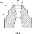
- the nozzle ports 126, 128 communicate drilling fluid flow from an interior of the crown 108 and over the bit face 110. Some or all of the nozzle ports 126, 128 may include a nozzle 170 ( FIG. 3 ) disposed therein.
- the nozzle ports 126 may direct jets or streams of the drilling fluid to clean and cool the cutting elements 114.
- the nozzle ports 126 and the nozzle ports 128 may also direct jets or streams of the drilling fluid to clean away formation cuttings, worn matrix material, abrasive particles shed from the matrix material, and other debris from between the blades 112.
- the bit 100 may comprise a reduced number of blades 112 as compared to conventional impregnated bits according to some embodiments of the present disclosure.
- the bit 100 may comprise a smaller number of blades 112 than bits offered by Baker Hughes Inc. under the trademark IREV®, which commonly includes at least twelve blades and as many as fifty blades.
- the bit 100 may comprise eight blades 112, as illustrated in FIGS. 2A and 2B .
- the bit 100 may comprise between six and twelve blades 112.
- each pair of blades 112 may be located equidistant from a neighboring pair of blades 112.
- the long channels 122 extending between the blades 112 may have a substantially equal width when measured at the same radial distance from the longitudinal axis 102.
- the pairs of blades 112 may be unequally distributed on the bit face 110.
- the long channels 122 may vary in width about the bit face 110 when measured at the same radial distance from the longitudinal axis 102.
- Each of the channels 122, 124 may increase in width as the channels 122, 124 extend radially outward across the bit face 110 such that the channels 122, 124 may be generally wedge shaped in the view of FIGS. 2A and 2B .
- the long channel 122 may have a minimum width measured adjacent to the nozzle port 126 located therein and a maximum width measured at a radially outer surface 121 within the long channel 122.
- the width of the long channels 122 may be greater than the width of similar channels formed in conventional impregnated bits and extending between a longitudinal axis and a gage thereof.
- the short channel 124 may have a minimum width measured at the radially innermost portion 125 adjacent the nozzle port 128.
- the short channel 124 may have a maximum width measured adjacent to the radially outer surface 127 within the channel 124.
- the width of the short channel 124 may be tailored based on the earth formation in which the bit 100 is intended for use. For example, as illustrated in FIG. 2B , the short channel 124 may have a greater width when the bit 100 is configured to form a wellbore in soft and less abrasive earth formations, such as clay and shale formations. As illustrated in FIG.
- the short channel 124 may have a reduced width when the bit 100 is configured to form a wellbore in hard and more abrasive earth formations, such as sandstone.
- the width of the short channel 124 may be tailored to increase or decrease fluid pressure therein in order to more effectively clean and remove debris between the blades 112 and to generally increase the cutting efficiency of the bit 100.
- the depth of the channels 124, 126 may also be tailored.
- the crown 108 may comprise a plurality of short channels 124 each having radially innermost portions 125 located equidistant from the longitudinal axis 102.
- the radially innermost portion 125 of each short channel 124 may be located circumferentially about the longitudinal axis 102 at substantially the same radial distance from the longitudinal axis 102.
- each short channel 124 have substantially the same length measured from the radially innermost portion 125 to the gage 116.
- the radially innermost portion 125 of at least one short channel 124 may be located at a radial distance from the longitudinal axis 102 different than the radially innermost portion 125 of at least one other short channel 124.
- the short channels 124 may vary in length measured from the radially innermost portion 125 to the gage 116.
- the openings of the nozzle ports 126, 128 may vary in size and/or shape.
- each the nozzle ports 126, 128 may comprise a round opening flush with or slightly recessed from the bit face 110.
- the openings may be circular, oval, or the like.
- the nozzle ports 128 located in the short channels 124 may be of a larger size than the nozzle ports 126 located in the long channels 122. In other words, a diameter of the nozzle ports 126 may be less than a diameter of the nozzle ports 128.
- the nozzle ports 128 located in the short channels 124 be substantially equal in size to the nozzle ports 126 in the long channels 122.
- the size of the nozzle ports 126, 128 may be varied to increase or decrease the fluid pressure within the respective fluid channels 122, 124.
- the nozzle 170 comprises a short tubular member 172 including an aperture 174 extending therethrough and in fluid communication with an interior of the crown 108 for discharging drilling fluid pumped from a formation surface through the drill string and onto the face 110 of the bit 100.
- the aperture 174 may have a bottleneck shaped portion as illustrated in FIG. 3 .
- the bottleneck shaped portion may be provided along the aperture 174 to increase the drilling fluid pressure provided therethrough and further to control the total flow area of nozzle ports 126, 128 providing drilling fluid over the bit face 110 and within the fluid channels 122, 124.
- the aperture 174 of the nozzle 170 may have any suitable shape known in the art. Generally, the size and shape of the aperture 174 of the nozzle may be adjusted to control the total flow area of nozzle ports 126, 128 providing fluid over the bit face 110 and within the fluid channels 122, 124.
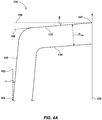
- FIG. 4A illustrates a partial and schematic cross-sectional plane view of the crown 108 of the bit 100.
- the plane of the cross-section of FIG. 4A includes the longitudinal axis 102 such that the plane extends through the center of the bit 100.
- FIG. 4A illustrates a profile 130 of the blades 112 extending between the longitudinal axis 102 and the gage 116.
- the blade profile 130 illustrates an exposure of an outer surface 132 of the blade 112, which engages the earth formation in operation, relative to an outer surface 134 of at least one of the short channel 124 and the long channel 122.
- the blade profile 130 further illustrates a depth D 130 of the fluid channels 122, 124 formed between the blades 112 of the bit 100 relative to the outer surface 132 of the blade 112.
- FIG. 4B is a comparative plot of the blade profile 130 of the bit 100 to an inverted cone blade profile 136 (shown in dashed lines) of a conventional impregnated drill bit, such as the bit disclosed in U.S. Patent Pub. 2010/0181116 , entitled “Impregnated Drill Bit with Diamond Pins,” filed January 16, 2009.
- the blade profile 136 of the conventional bit illustrates an exposure of an outer surface 138 of a blade relative to an outer surface 140 of fluid channels of the conventional bit.
- the blade profile 136 further illustrates a depth D 136 of the fluid channels between the blades of a conventional bit relative to the outer surface 138 of the blade.
- a conventional bit may comprise a plurality of regions between a longitudinal axis 137 and a gage 142 of the bit. These regions include a cone region 144, a nose region 146, a shoulder region 148, and a gage region 150.
- the cone region 144 may be located near a center line of the conventional bit, such as near the longitudinal axis 137.
- the outer surface 138 of the blade in the cone region 144 may extend in a generally planar manner as indicated by a line 152 tangent to the outer surface 138 of the blade.
- the tangent line 152 may extend at an angle relative to a line 154 perpendicular to the longitudinal axis 137.
- the angle ⁇ may be measured between the tangent line 152 and line 154 with negative angles being measured in the counterclockwise direction relative to the line 154 and positive angles being measured in the clockwise directive relative to the line 154.
- the angle ⁇ of the outer surface 138 may extend at a positive acute angle ⁇ between about 15° to about 25° and, more particularly, about 20° relative to the line 154.
- the outer surface 138 of blades of the conventional bit may have the shape of an inverted cone in the cone region 144 such that the cone region 144 extends downward in the view of FIG. 4B .
- the bit is inverted from its view in FIG. 4B such that the outer surface 138 of the blades in the cone region 144 extends upward and into the crown of the bit away from the earth formation.
- the cone region 144 does not experience as much, or as fast, rotational movement relative to the earth formation and, therefore, commonly experiences less wear than the other portions of the blade profile 136.
- the nose region 146 includes more radially distal surfaces on a face of the bit and the uppermost surface in the view of FIG. 4B or, in operation, the lowermost surface on the bit when the bit is inverted. As the lowermost, or axially leading, surface during operation, the nose region 146 experiences greater wear than the cone region 144.
- the shoulder region 148 extends between the nose region 146 until the outer surface 138 of the blade is essentially vertical in the gage region 150.
- the shoulder region 148 may experience a greater amount of and most rapid movement of the bit relative to the earth formation. As a result, the shoulder region 148 experiences much greater wear than the cone region 144. Thus, the shoulder region 148 and/or nose region 146 may experience the greatest wear as compared to any other region of the bit.
- the gage region 150 including the gage 142 of the bit also experiences more wear than the cone region 144 because the gage region 150 experience the most, and most rapid, relative rotational movement with respect to the earth formation. However, due to the substantially vertical slope of the blade in the gage region 150 contacting the well bore wall, the gage region 150 experiences less wear than the nose region 146 and/or shoulder region 148. In view of the foregoing, the conventional bit experiences an inconsistent rate of wear across the blade profile 136.
- the exposure of the blades over the fluid channels of the conventional bit or the depth D 136 of the fluid channels relative to the blades may vary across and/or within each of the cone region 144, nose region 146, shoulder region 148, and gage region 150.
- each region of the conventional bit experiences a different degree of wear with the nose region 146 and/or shoulder region 148 experiencing the greatest wear greater contact with the earth formation than other regions of the bit.
- the exposure of the blades over the fluid channels is reduced until the outer surface 138 of the blade is coincident with the outer surface 140 of the fluid channel particularly in the nose region 146 and/or shoulder region 148.
- the bit face 110 may have a shallow conical shape with the apex 107 of the cone located coincident with the longitudinal axis 102.
- the outer surface 132 of the blades 112 may at least partially define the bit face 110.
- the bit 100 may lack an inverted cone region as illustrated in FIGS. 4A and 4B .
- the outer surface 132 of the blade 112 extends substantially linearly from the longitudinal axis 102 across a majority of the bit face 110. As illustrated by a line 156 tangent to the outer surface 132 of the blade 112 in FIG.
- the blade 112 may extend in a substantially linear manner in a region 160 corresponding to each of the cone region 144 and the nose region 146 of the conventional bit.
- the line 156 lies in the cross-sectional plane of FIG. 4A , which as previously stated extends through the longitudinal axis 102 or the center of the bit 100.
- the outer surface 132 of the blade 112 may be formed at an acute angle ⁇ relative to a line 158 perpendicular to the longitudinal axis 102 of the bit 100 on the face 110 of the bit 100.
- the angle ⁇ may be measured between the tangent line 156 and line 158 with negative angles being measured in the counterclockwise direction relative to the line 158 and positive angles being measured in the clockwise directive relative to the line 158.
- the outer surface 132 of the blades 112 extends down, or at a negative angle ⁇ from, relative to the line 158 and from the longitudinal axis 102.
- the bit 100 is inverted such that the outer surface 132 of the blades 112 extends upward (e.g., towards the proximal end 103 of the bit 100) and at the angle ⁇ from the distalmost point of the bit face 110 (e.g., the apex 107) coincident with the longitudinal axis 102.
- the acute angle ⁇ may extend in a range from about 0° to about -5° and, more particularly, in a range from about -1° to about -5°.
- the exposure of the blades 112 over the fluid channels 122, 124 of the bit 100 or the depth D 130 of the fluid channels 122, 124 relative to the blades 112 may be constant in areas of the bit face 110 corresponding to at least one of the cone region 144, nose region 146, and shoulder region 148 of the conventional bit.
- the depth D 130 of each of the fluid channels 122, 124 relative to the outer surface 132 of the blade 112 may be equal.
- the outer surface 134 ( e . g ., a bottom surface) of the fluid channels 122, 124 may be located equidistant from the outer surface 132 of the blade 112.
- the outer surface 134 of either the short channels 124 or the long channels 122 may be recessed at a greater depth from the outer surface 132 of the blade 112 compared to the other channel.
- the blade profile 130 may experience substantially even wear over the bit face 110 by virtue of the substantially planar blade profile 130 across the bit face 110.
- the outer surface 132 of the blades 112 may experience a substantially even amount of movement of the bit 100 relative to the earth formation and a substantially even force from the earth formation may be exerted against the bit face 110 as compared to the conventional bit described above.
- the blade profile 130 may experience a more consistent rate of wear across the bit face 110 region.
- the bit 100 may have a reduced likelihood of balling, a more stable ROP throughout the life of the bit, and an extended bit life relative to conventional bits described above.
- FIG. 4A further illustrates an indent angle ⁇ of the gage 116 of the bit 100.
- the indent angle ⁇ has been exaggerated for the purpose of explanation in FIG. 4a .
- the gage of conventional bit extends substantially vertically and in parallel to the longitudinal axis 137 of the bit.
- the gage 116 of the bit 100 may extend axially and radially inwards from an axially trailing edge 157 to axially leading edge 159, such that the gage 116 may not extend in a parallel direction to the longitudinal axis 102 of the bit 100.
- the gage 116 of the bit 100 may extend away from the earth formation during operation thereof.
- the indent angle ⁇ may be measured relative to a line 162 tangent to a radially outermost point 164 of the gage 116 and extending parallel to the longitudinal axis 102 of the bit 100.
- the indent angle ⁇ may be measured between a surface of the gage 116 along the blade 112 and the tangent line 162 with negative angles being measured in the counterclockwise direction relative to the line 162 and positive angles being measured in the clockwise directive relative to the line 162.
- the indent angle ⁇ may be greater than 0° and less than or equal to about 7°. More particularly, the indent angle ⁇ may greater than 0° and less than or equal to about 3°.
- the bit 100 may be suitable to drill deviated wellbores in earth formations, which include a generally vertical borehole drilled from an earth surface into the formation to culminate in a more horizontal portion or portions within a particular rock formation layer.
- a curved portion of the wellbore may extend between the vertical portion and horizontal portion thereof.
- the ability of a drill bit, such as the bit 100, to deviate from the linear path of the vertical portion to the horizontal portion may be defined by its potential radius of curvature.
- the gage 116 By forming the gage 116 to extend away from the earth formation and radially inward towards the longitudinal axis 102 at the indent angle ⁇ , the amount of contact between the gage 116 and the formation may be reduced, which enables the bit 100 to deviate between the vertical portion and horizontal portion of the wellbore over a shorter distance.
- the indent angle ⁇ of the gage 116 may shorten the minimum radius of curvature of the wellbore trajectory that may be drilled by the bit 100.
- the bit 100 may deviate (for example) between a vertical portion and horizontal portion of the wellbore over a distance of about 300 feet (about 91 meters) and, more particularly, about 100 feet (about 30.5 meters) or less.
Landscapes
- Engineering & Computer Science (AREA)
- Life Sciences & Earth Sciences (AREA)
- Geology (AREA)
- Mining & Mineral Resources (AREA)
- Mechanical Engineering (AREA)
- Physics & Mathematics (AREA)
- Environmental & Geological Engineering (AREA)
- Fluid Mechanics (AREA)
- General Life Sciences & Earth Sciences (AREA)
- Geochemistry & Mineralogy (AREA)
- Earth Drilling (AREA)
Abstract
Description
- The present invention relates generally to impregnated drag bits for drilling earth formations and, more particularly, to the manner in which the blades and fluid channels on the bit are formed and configured.
- So-called "impregnated" drag bits are used conventionally for drilling hard and/or abrasive rock formations, such as sandstones. Such conventional impregnated drill bits typically employ a cutting face having blades or inserts comprising superabrasive cutting particles, such as natural or synthetic diamond grit, dispersed within a metal or metal alloy matrix material. As such a bit drills, the matrix material wears away, exposed cutting particles are lost as the surrounding matrix material to which the particles are mechanically and metalurgically bonded is removed, and new cutting particles previously buried within the matrix material become exposed. These diamond particles may be cast integrally with the body of the bit, as in a low-pressure infiltration process to form blades comprising the diamond particles and matrix material, or inserts comprising the diamond particles and matrix material may be preformed separately from the bit body, such as in a hot isostatic press (HIP) sintering process, and the inserts may be attached subsequently to the bit body by brazing. In other processes, such preformed inserts may be placed within a mold in which the bit body is cast using an infiltration process. In such a process, the inserts become bonded to the bit body as the bit body is formed over and around the inserts.
- Conventional impregnated bits generally exhibit a poor hydraulics design by employing what is referred to in the industry as a "crow's foot" to distribute drilling fluid across the bit face and providing only minimal flow area. Further, conventional impregnated bits do not drill effectively when the bit encounters softer and less abrasive layers of rock, such as shales. When drilling through shale, or other soft formations, with a conventional impregnated drag bit, the cutting structure tends to quickly clog or "ball up" with formation material, making the drill bit ineffective. The softer formations can also plug up fluid courses formed in the drill bit, causing heat buildup and premature wear of the bit. Therefore, when shale-type formations are encountered, a more aggressive bit is desired to achieve a higher rate of penetration (ROP). It follows, therefore, that selection of a bit for use in a particular drilling operation becomes more complicated when it is expected that formations of more than one type will be encountered during the drilling operation.
- In some embodiments of the present disclosure, an impregnated bit for forming a wellbore in an earth formation includes a bit body having a proximal end, a distal end, and a longitudinal axis. A bit face is located at the distal end and extends between the longitudinal axis and a gage. The bit face comprises at least one blade extending radially outward from the longitudinal axis toward the gage and comprising an outer surface to engage formation material. The outer surface of the blade extends substantially linearly from a distalmost point of the bit face coincident with the longitudinal axis and at an acute angle relative to a line perpendicular to the longitudinal axis of the bit body.
- In additional embodiments of the present disclosure, an impregnated bit for forming a wellbore in an earth formation includes a bit body having a proximal end, a distal end, and a longitudinal axis. A bit face is located at the distal end and extends between the longitudinal axis and a gage. The bit face comprises at least one blade extending radially outward from the longitudinal axis toward the gage and comprising an outer surface to engage formation material. The bit face further comprises a first fluid channel recessed within the bit face adjacent the at least one blade and extending radially across the bit face from a radially innermost portion proximate to the longitudinal axis to the gage and a second fluid channel recessed within the bit face adjacent the at least one blade and extending radially across a portion of the bit face from a radially innermost portion located further from the longitudinal axis relative to the radially innermost portion of the first fluid channel to the gage. The bottoms of the first fluid channel and the second fluid channel are recessed equidistant from the outer surface of the at least one blade.
- In yet further embodiments of the present disclosure, an impregnated bit for forming a wellbore in an earth formation includes a bit body having a bit face extending between a longitudinal axis and a gage. The bit face comprises a plurality of blades extending radially outward from the longitudinal axis and axially along the gage, wherein the plurality of blades comprises a plurality of pairs of blades circumferentially spaced about the longitudinal axis. The bit face further comprises a first fluid channel extending between circumferentially adjacent pairs of blades and radially across the bit face from a radially innermost portion proximate to the longitudinal axis to the gage and a second fluid channel extending between each blade of the pairs of blades and radially across a portion of the bit face from a radially innermost portion located further from the longitudinal axis relative to the radially innermost portion of the first fluid channel to the gage.
- While the specification concludes with claims particularly pointing out and distinctly claiming what are regarded as embodiments of the present disclosure, various features and advantages of embodiments of the disclosure may be more readily ascertained from the following description of example embodiments of the disclosure when read in conjunction with the accompanying drawings, in which:
-
FIG. 1 is a perspective view of drill bit according to some embodiments of the present disclosure; -
FIGS. 2a and 2b are views of a bit face of the drill bit ofFIG.1 according to some embodiments of the present disclosure; -
FIG. 3 is a cross-sectional side view of a nozzle according to some embodiments of the present disclosure; -
FIG. 4a is diagram of a partial blade profile of the drill bit ofFIG. 1 according to some embodiments of the present disclosure; and -
FIG. 4b is a comparative diagram of the partial blade profile ofFIG. 4a and a partial blade profile of a conventional drill bit. - The illustrations presented herein are not meant to be actual views of any particular drill bit or component thereof, but are merely idealized representations which are employed to describe embodiments of the present disclosure.
- As used herein, the term "substantially" in reference to a given parameter, property, or condition means and includes to a degree that one of ordinary skill in the art would understand that the given parameter, property, or condition is met with a degree of variance, such as within acceptable manufacturing tolerances. By way of example, depending on the particular parameter, property, or condition that is substantially met, the parameter, property, or condition may be at least 90.0% met, at least 95.0% met, at least 99.0% met, or even at least 99.9% met.
- As used herein, the term "about" in reference to a given parameter is inclusive of the stated value and has the meaning dictated by the context (e.g., it includes the degree of error associated with measurement of the given parameter).
- As used herein, the term "and/or" includes any and all combinations of one or more of the associated listed items.
-
FIG. 1 is a perspective view of animpregnated drag bit 100 according to embodiments of the present disclosure. For purposes of description, thebit 100 is inverted from its normal face-down orientation during operation of thebit 100 while forming a wellbore in an earth formation. Thebit 100 may have alongitudinal axis 102, conventionally the center line of abit body 104 and the axis about which thebit 100 rotates in operation. Thebit body 104 may comprise ashank 106 for connection to a drill string (not shown). Theshank 106 may be coupled to acrown 108 of thebit 100. In some embodiments, thecrown 108 may comprise an impregnated material, which refers to a matrix material having superabrasive particles or material including, but not limiting to, natural or synthetic diamond grit dispersed therein. Thecrown 108 may comprise abit face 110 extending from thelongitudinal axis 102 to agage 116. Thebit face 110 is illustrated in a front view inFIGS. 2a and 2b . As best illustrated inFIG. 1 , thebit face 110 may have a shallow conical shape having anapex 107 coincident with thelongitudinal axis 102 of thebit 100. - In operation, the
bit 100 is extended into the wellbore by a drill string connected to a drilling rig located at a surface of the earth formation in which the wellbore is formed. Thus, thebit 100 is inverted from the view ofFIG. 1 in operation such that thebit face 110 engages and cuts formation material within the borehole. In other words, thebit face 110 is located distal from the surface of the earth formation where the drilling rig is located, and thebit face 110 comprises adistal end 101 of thebit 100. A distalmost point of thebit face 110 may be located coincident with thelongitudinal axis 102. For example, in embodiments in which thebit face 110 is conical in shape, the distal most point of thebit face 110 may comprise theapex 107 of thebit face 110. Theshank 106, which may be connected to a drill string, may be located proximal to the surface of the earth formation comparative to thebit face 110. In other words, theshank 106 comprises aproximal end 103 of thebit 100. - With continued reference to
FIGS. 1 ,2a, and 2b , thecrown 108 may comprise a plurality ofblades 112 circumferentially spaced about thelongitudinal axis 102 and extending generally radially outward from thelongitudinal axis 102 to thegage 116. Theblades 112 may extend in a generally linear fashion (as opposed to a spiral or curved fashion) from thelongitudinal axis 102 to thegage 116 in some embodiments. The plurality ofblades 112 may also extend axially along thegage 116. Thegage 116 may comprise a radially outermost surface of thebit 100 surrounding the bit face 110 for engaging a sidewall of the wellbore. In some embodiments, one ormore cutting elements 114 may be mounted to at least oneblade 112. More particularly, the cuttingelements 114 may be mounted on a rotationally leadingedge 113 of the at least oneblade 112 opposite a rotationally trailingedge 115 of the at least oneblade 112. The cuttingelements 114 may be located proximate to thelongitudinal axis 102 and may be generally oriented to face the direction of rotation of thebit 100 about thelongitudinal axis 102. - In some embodiments, the cutting
elements 114 may comprise polycrystalline diamond compact (PDC) cutting elements. The polycrystallinediamond cutting elements 114 may each comprise a supportingsubstrate 119 having a diamond table 117 thereon. The cuttingelements 114 may be oriented to remove material from the underlying earth formation by a shearing action as thedrill bit 100 is rotated about thelongitudinal axis 102 and by contacting the formation material with cutting edges and cutting surfaces of the cuttingelements 114. In some embodiments, the cuttingelements 114 may comprise PDC cutting elements offered by DiaroTech SA that include a diamond table and an impregnated substrate. The impregnated substrate may comprise a matrix material having a plurality of abrasive particles including, but not limited to, diamond particles dispersed therein. In operation, the impregnated substrate may provide additional cutting action when the diamond table has at least partially worn away. For example, the impregnated substrate may be self-sharpening such that, as the matrix material of the substrate wears away, superabrasive particles disposed and held therein may be shed and fresh, unworn abrasive particles may be exposed. In such embodiments, the useful life of the cuttingelements 114 may be extended by providing cutting action by the substrate in addition to the shearing action provided by the diamond table. Nonetheless, it is recognized that any other suitable type of cutting element, including without limitation natural diamonds, may be utilized in embodiments of the present disclosure. - In operation, the
bit 100 may be run into a wellbore and "broken-in" or "sharpened" by drilling into an earth formation at a selected weight-on-bit (WOB) as thebit 100 is rotated about thelongitudinal axis 102. In the initial stages of penetration of the earth formation, thebit 100 may be run into the wellbore at an increased rate of penetration (ROP) to wear away the matrix material of thebit 100 and expose the abrasive particles disposed therein. Thebit 100 may be "sharpened" when the abrasive particles are sufficiently exposed to cut the earth formation. Once thebit 100 is "sharpened," the ROP stabilizes. - In some embodiments, the rotationally trailing
edges 115 of theblades 112 may be provided with a large radius of curvature R115 compared to conventional impregnated drill bits. In some embodiments, the rotationally trailingedges 115 may exhibit a radius of curvature R115 greater than 0.1 inch and less than or equal to about 0.5 inch. By virtue of the curved rotationally trailingedge 115, an initial area of anouter surface 132 of theblade 112 that engages and cuts formation material is smaller than the final area of theouter surface 132 of theblade 112 that engages the formation after wear of the bit. As the matrix material of thecrown 108 continues to wear away, the area of theouter surface 132 of theblades 112 that engages the formation increases. Theblades 112 of thebit 100 may be "broken-in" or "sharpened" when the curved rotationally trailingsurface 115 has worn entirely away. When thebit 100 is "sharpened", the ROP of thebit 100 may stabilize as thebit 100 continues to wear away from contact with the formation material. In view of the foregoing, thebit 100 may wear to a "sharpened" state at an increased rate over conventional impregnated bits lacking a large radius of curvature along a rotationally trailing edge of the blades thereof. - The
crown 108 may also comprise a plurality of fluid channels between and recessed from theblades 112 and extending tojunk slots 120 in thegage 116. The plurality of fluid channels may include at least onelong channel 122 and at least oneshort channel 124. As best illustrated inFIGS. 2a and 2b , thelong channel 122 may extend radially across the bit face 110 from proximate thelongitudinal axis 102 to thegage 116. Thelong channels 122 may comprise a radiallyinnermost portion 123 located proximate to thelongitudinal axis 102. Thelong channel 122 may extend between and separate circumferentiallyadjacent blades 112. In some embodiments, theblades 112 of thebit 100 may be formed in pairs ofblades 112. In such embodiments, each pair ofblades 112 may be separated from a neighboring (e.g., circumferentially adjacent) pair ofblades 112 by thelong channel 122. Eachblade 112 of the pair ofblades 112 may be separated by theshort channel 124. Theshort channel 124 may extend partially across the bit face 110 such that theshort channel 124 extends radially across a lesser portion of the bit face 110 than thelong channel 122. In other words, theshort channel 124 may comprise a radiallyinnermost portion 125 located further from thelongitudinal axis 102 relative to the radiallyinnermost portion 123 of thelong channels 122. Theshort channel 124 may extend with ablade 112 to form the pair ofblades 112. - Each of the plurality of
long channels 122 may comprise anozzle port 126. Thenozzle port 126 may be located proximate to or within the radially innermost portion of thelong channel 122. In some embodiments, thenozzle port 126 may be located proximate to at least one of the cuttingelements 114. Each of the plurality ofshort channels 124 may also comprise anozzle port 128. Thenozzle ports crown 108 and over thebit face 110. Some or all of thenozzle ports FIG. 3 ) disposed therein. Thenozzle ports 126 may direct jets or streams of the drilling fluid to clean and cool the cuttingelements 114. Thenozzle ports 126 and thenozzle ports 128 may also direct jets or streams of the drilling fluid to clean away formation cuttings, worn matrix material, abrasive particles shed from the matrix material, and other debris from between theblades 112. - The
bit 100 may comprise a reduced number ofblades 112 as compared to conventional impregnated bits according to some embodiments of the present disclosure. For example, thebit 100 may comprise a smaller number ofblades 112 than bits offered by Baker Hughes Inc. under the trademark IREV®, which commonly includes at least twelve blades and as many as fifty blades. In some embodiments, thebit 100 may comprise eightblades 112, as illustrated inFIGS. 2A and 2B . In other embodiments, thebit 100 may comprise between six and twelveblades 112. In some embodiments, each pair ofblades 112 may be located equidistant from a neighboring pair ofblades 112. In such embodiments, thelong channels 122 extending between theblades 112 may have a substantially equal width when measured at the same radial distance from thelongitudinal axis 102. In other embodiments, the pairs ofblades 112 may be unequally distributed on thebit face 110. In such embodiments, thelong channels 122 may vary in width about the bit face 110 when measured at the same radial distance from thelongitudinal axis 102. - Each of the
channels channels channels FIGS. 2A and 2B . Thelong channel 122 may have a minimum width measured adjacent to thenozzle port 126 located therein and a maximum width measured at a radiallyouter surface 121 within thelong channel 122. By virtue of the reduced number ofblades 112, the width of thelong channels 122 according to embodiments of the present disclosure may be greater than the width of similar channels formed in conventional impregnated bits and extending between a longitudinal axis and a gage thereof. - Like the
long channel 122, theshort channel 124 may have a minimum width measured at the radiallyinnermost portion 125 adjacent thenozzle port 128. Theshort channel 124 may have a maximum width measured adjacent to the radiallyouter surface 127 within thechannel 124. In some embodiments, the width of theshort channel 124 may be tailored based on the earth formation in which thebit 100 is intended for use. For example, as illustrated inFIG. 2B , theshort channel 124 may have a greater width when thebit 100 is configured to form a wellbore in soft and less abrasive earth formations, such as clay and shale formations. As illustrated inFIG. 2a , theshort channel 124 may have a reduced width when thebit 100 is configured to form a wellbore in hard and more abrasive earth formations, such as sandstone. The width of theshort channel 124 may be tailored to increase or decrease fluid pressure therein in order to more effectively clean and remove debris between theblades 112 and to generally increase the cutting efficiency of thebit 100. As discussed in further detail with regard toFIG. 4A and4B , the depth of thechannels - In some embodiments, the
crown 108 may comprise a plurality ofshort channels 124 each having radiallyinnermost portions 125 located equidistant from thelongitudinal axis 102. In other words, the radiallyinnermost portion 125 of eachshort channel 124 may be located circumferentially about thelongitudinal axis 102 at substantially the same radial distance from thelongitudinal axis 102. In such embodiments, eachshort channel 124 have substantially the same length measured from the radiallyinnermost portion 125 to thegage 116. In other embodiments, the radiallyinnermost portion 125 of at least oneshort channel 124 may be located at a radial distance from thelongitudinal axis 102 different than the radiallyinnermost portion 125 of at least one othershort channel 124. In other words, theshort channels 124 may vary in length measured from the radiallyinnermost portion 125 to thegage 116. - The openings of the
nozzle ports nozzle ports bit face 110. The openings may be circular, oval, or the like. In some embodiments, thenozzle ports 128 located in theshort channels 124 may be of a larger size than thenozzle ports 126 located in thelong channels 122. In other words, a diameter of thenozzle ports 126 may be less than a diameter of thenozzle ports 128. In other embodiments, thenozzle ports 128 located in theshort channels 124 be substantially equal in size to thenozzle ports 126 in thelong channels 122. The size of thenozzle ports fluid channels - As illustrated in
FIG. 3 , thenozzle 170 comprises ashort tubular member 172 including anaperture 174 extending therethrough and in fluid communication with an interior of thecrown 108 for discharging drilling fluid pumped from a formation surface through the drill string and onto theface 110 of thebit 100. In some embodiments, theaperture 174 may have a bottleneck shaped portion as illustrated inFIG. 3 . The bottleneck shaped portion may be provided along theaperture 174 to increase the drilling fluid pressure provided therethrough and further to control the total flow area ofnozzle ports bit face 110 and within thefluid channels aperture 174 of thenozzle 170 may have any suitable shape known in the art. Generally, the size and shape of theaperture 174 of the nozzle may be adjusted to control the total flow area ofnozzle ports bit face 110 and within thefluid channels -
FIG. 4A illustrates a partial and schematic cross-sectional plane view of thecrown 108 of thebit 100. The plane of the cross-section ofFIG. 4A includes thelongitudinal axis 102 such that the plane extends through the center of thebit 100. More particularly,FIG. 4A illustrates aprofile 130 of theblades 112 extending between thelongitudinal axis 102 and thegage 116. Theblade profile 130 illustrates an exposure of anouter surface 132 of theblade 112, which engages the earth formation in operation, relative to anouter surface 134 of at least one of theshort channel 124 and thelong channel 122. Theblade profile 130 further illustrates a depth D130 of thefluid channels blades 112 of thebit 100 relative to theouter surface 132 of theblade 112. -
FIG. 4B is a comparative plot of theblade profile 130 of thebit 100 to an inverted cone blade profile 136 (shown in dashed lines) of a conventional impregnated drill bit, such as the bit disclosed inU.S. Patent Pub. 2010/0181116 , entitled "Impregnated Drill Bit with Diamond Pins," filed January 16, 2009. Like theblade profile 130 according to embodiments of the present disclosure, theblade profile 136 of the conventional bit illustrates an exposure of anouter surface 138 of a blade relative to anouter surface 140 of fluid channels of the conventional bit. Theblade profile 136 further illustrates a depth D136 of the fluid channels between the blades of a conventional bit relative to theouter surface 138 of the blade. As known in the art, a conventional bit may comprise a plurality of regions between a longitudinal axis 137 and agage 142 of the bit. These regions include acone region 144, anose region 146, ashoulder region 148, and agage region 150. - The
cone region 144 may be located near a center line of the conventional bit, such as near the longitudinal axis 137. Theouter surface 138 of the blade in thecone region 144 may extend in a generally planar manner as indicated by aline 152 tangent to theouter surface 138 of the blade. Thetangent line 152 may extend at an angle relative to aline 154 perpendicular to the longitudinal axis 137. The angle α may be measured between thetangent line 152 andline 154 with negative angles being measured in the counterclockwise direction relative to theline 154 and positive angles being measured in the clockwise directive relative to theline 154. In conventional bits, the angle α of theouter surface 138 may extend at a positive acute angle α between about 15° to about 25° and, more particularly, about 20° relative to theline 154. As illustrated inFIG. 4B , theouter surface 138 of blades of the conventional bit may have the shape of an inverted cone in thecone region 144 such that thecone region 144 extends downward in the view ofFIG. 4B . In operation, the bit is inverted from its view inFIG. 4B such that theouter surface 138 of the blades in thecone region 144 extends upward and into the crown of the bit away from the earth formation. As a result, thecone region 144 does not experience as much, or as fast, rotational movement relative to the earth formation and, therefore, commonly experiences less wear than the other portions of theblade profile 136. - The
nose region 146 includes more radially distal surfaces on a face of the bit and the uppermost surface in the view ofFIG. 4B or, in operation, the lowermost surface on the bit when the bit is inverted. As the lowermost, or axially leading, surface during operation, thenose region 146 experiences greater wear than thecone region 144. - The
shoulder region 148 extends between thenose region 146 until theouter surface 138 of the blade is essentially vertical in thegage region 150. Theshoulder region 148 may experience a greater amount of and most rapid movement of the bit relative to the earth formation. As a result, theshoulder region 148 experiences much greater wear than thecone region 144. Thus, theshoulder region 148 and/ornose region 146 may experience the greatest wear as compared to any other region of the bit. - The
gage region 150 including thegage 142 of the bit also experiences more wear than thecone region 144 because thegage region 150 experience the most, and most rapid, relative rotational movement with respect to the earth formation. However, due to the substantially vertical slope of the blade in thegage region 150 contacting the well bore wall, thegage region 150 experiences less wear than thenose region 146 and/orshoulder region 148. In view of the foregoing, the conventional bit experiences an inconsistent rate of wear across theblade profile 136. - As further illustrated in
FIG. 4B , the exposure of the blades over the fluid channels of the conventional bit or the depth D136 of the fluid channels relative to the blades may vary across and/or within each of thecone region 144,nose region 146,shoulder region 148, andgage region 150. As previously stated, each region of the conventional bit experiences a different degree of wear with thenose region 146 and/orshoulder region 148 experiencing the greatest wear greater contact with the earth formation than other regions of the bit. As the blade wears, the exposure of the blades over the fluid channels is reduced until theouter surface 138 of the blade is coincident with theouter surface 140 of the fluid channel particularly in thenose region 146 and/orshoulder region 148. This extensive wear at first reduces, and then may prevent, drilling fluid from the nozzle ports from flowing across the bit face within the fluid channels therein. As a result, formation cuttings and other abrasive material may accumulate on the bit face and within the fluid channels between the blades. This accumulation of debris reduces drilling efficiency significantly, and may in certain formations such as shales and clays, lead to a phenomenon known as balling, which can reduce the ROP of the bit and result in premature failure of the bit. - As previously described with reference to
FIG. 1 , the bit face 110 may have a shallow conical shape with the apex 107 of the cone located coincident with thelongitudinal axis 102. Theouter surface 132 of theblades 112 may at least partially define thebit face 110. Unlike the conventional bit, thebit 100 may lack an inverted cone region as illustrated inFIGS. 4A and4B . In some embodiments, theouter surface 132 of theblade 112 extends substantially linearly from thelongitudinal axis 102 across a majority of thebit face 110. As illustrated by aline 156 tangent to theouter surface 132 of theblade 112 inFIG. 4A , theblade 112 may extend in a substantially linear manner in a region 160 corresponding to each of thecone region 144 and thenose region 146 of the conventional bit. Theline 156 lies in the cross-sectional plane ofFIG. 4A , which as previously stated extends through thelongitudinal axis 102 or the center of thebit 100. - In some embodiments, the
outer surface 132 of theblade 112 may be formed at an acute angle β relative to aline 158 perpendicular to thelongitudinal axis 102 of thebit 100 on theface 110 of thebit 100. The angle β may be measured between thetangent line 156 andline 158 with negative angles being measured in the counterclockwise direction relative to theline 158 and positive angles being measured in the clockwise directive relative to theline 158. As illustrated inFIGS. 4A and4B , theouter surface 132 of theblades 112 extends down, or at a negative angle β from, relative to theline 158 and from thelongitudinal axis 102. However, in operation, thebit 100 is inverted such that theouter surface 132 of theblades 112 extends upward (e.g., towards theproximal end 103 of the bit 100) and at the angle β from the distalmost point of the bit face 110 (e.g., the apex 107) coincident with thelongitudinal axis 102. In some embodiments, the acute angle β may extend in a range from about 0° to about -5° and, more particularly, in a range from about -1° to about -5°. Also unlike the conventional bit, the exposure of theblades 112 over thefluid channels bit 100 or the depth D130 of thefluid channels blades 112 may be constant in areas of the bit face 110 corresponding to at least one of thecone region 144,nose region 146, andshoulder region 148 of the conventional bit. In some embodiments, the depth D130 of each of thefluid channels outer surface 132 of theblade 112 may be equal. In other words, the outer surface 134 (e.g., a bottom surface) of thefluid channels outer surface 132 of theblade 112. In other embodiments, theouter surface 134 of either theshort channels 124 or thelong channels 122 may be recessed at a greater depth from theouter surface 132 of theblade 112 compared to the other channel. - Without being bound by any particular theory, the
blade profile 130 may experience substantially even wear over the bit face 110 by virtue of the substantiallyplanar blade profile 130 across thebit face 110. For example, theouter surface 132 of theblades 112 may experience a substantially even amount of movement of thebit 100 relative to the earth formation and a substantially even force from the earth formation may be exerted against the bit face 110 as compared to the conventional bit described above. As a result, theblade profile 130 may experience a more consistent rate of wear across the bit face 110 region. In view of the foregoing, thebit 100 may have a reduced likelihood of balling, a more stable ROP throughout the life of the bit, and an extended bit life relative to conventional bits described above. -
FIG. 4A further illustrates an indent angle γ of thegage 116 of thebit 100. The indent angle γ has been exaggerated for the purpose of explanation inFIG. 4a . As known in the prior art and as previously described above, the gage of conventional bit extends substantially vertically and in parallel to the longitudinal axis 137 of the bit. Unlike the conventional bit, in some embodiments of the present disclosure, thegage 116 of thebit 100 may extend axially and radially inwards from an axially trailing edge 157 to axially leading edge 159, such that thegage 116 may not extend in a parallel direction to thelongitudinal axis 102 of thebit 100. In other words, thegage 116 of thebit 100 may extend away from the earth formation during operation thereof. - The indent angle γ may be measured relative to a
line 162 tangent to a radiallyoutermost point 164 of thegage 116 and extending parallel to thelongitudinal axis 102 of thebit 100. In other words, the indent angle γ may be measured between a surface of thegage 116 along theblade 112 and thetangent line 162 with negative angles being measured in the counterclockwise direction relative to theline 162 and positive angles being measured in the clockwise directive relative to theline 162. In some embodiments, the indent angle γ may be greater than 0° and less than or equal to about 7°. More particularly, the indent angle γ may greater than 0° and less than or equal to about 3°. - In operation, the
bit 100 may be suitable to drill deviated wellbores in earth formations, which include a generally vertical borehole drilled from an earth surface into the formation to culminate in a more horizontal portion or portions within a particular rock formation layer. A curved portion of the wellbore may extend between the vertical portion and horizontal portion thereof. The ability of a drill bit, such as thebit 100, to deviate from the linear path of the vertical portion to the horizontal portion may be defined by its potential radius of curvature. By forming thegage 116 to extend away from the earth formation and radially inward towards thelongitudinal axis 102 at the indent angle γ, the amount of contact between thegage 116 and the formation may be reduced, which enables thebit 100 to deviate between the vertical portion and horizontal portion of the wellbore over a shorter distance. In other words, the indent angle γ of thegage 116 may shorten the minimum radius of curvature of the wellbore trajectory that may be drilled by thebit 100. For example, thebit 100 according to some embodiments may deviate (for example) between a vertical portion and horizontal portion of the wellbore over a distance of about 300 feet (about 91 meters) and, more particularly, about 100 feet (about 30.5 meters) or less. - While the disclosed structures and methods are susceptible to various modifications and alternative forms in implementation thereof, specific embodiments have been shown by way of example in the drawings and have been described in detail herein. However, it should be understood that the present disclosure is not limited to the particular forms disclosed. Rather, the present invention encompasses all modifications, combinations, equivalents, variations, and alternatives falling within the scope of the present disclosure as defined by the following appended claims and their legal equivalents.
Claims (15)
- An impregnated bit for forming a wellbore in an earth formation, comprising:a bit body having a proximal end, a distal end, and a longitudinal axis; anda bit face located at the distal end and extending between the longitudinal axis and a gage, the bit face comprising at least one blade extending radially outward from the longitudinal axis toward the gage and comprising an outer surface to engage formation material;wherein the outer surface of the at least one blade extends substantially linearly from a distalmost point of the bit face coincident with the longitudinal axis and at an acute angle relative to a line perpendicular to the longitudinal axis of the bit body.
- The impregnated bit of claim 1, wherein the acute angle relative to the line perpendicular to the longitudinal axis is either: (i) greater than 0 degrees and less than or equal to 5 degrees; and/or (ii) is about 1 degree.
- The impregnated bit of claim 1 or 2, further comprising at least one cutting element mounted on the at least one blade proximate to the longitudinal axis, preferably wherein the at least one cutting element comprises a diamond table mounted to an impregnated substrate, the impregnated substrate comprising a plurality of abrasive particles dispersed in a matrix material.
- The impregnated bit of any preceding claim, wherein the bit face is conical in shape having an apex of the conical shape located coincident with the longitudinal axis.
- The impregnated bit of any preceding claim, wherein the at least one blade extends axially along the gage, and wherein the outer surface of the blade along the gage extends linearly and radially inward toward the longitudinal axis from a trailing edge to a leading edge of the gage.
- The impregnated bit of claim 5, wherein the outer surface of the blade extends at an acute angle relative to a line tangent the outer surface of the blade in the gage and extending parallel to the longitudinal axis, preferably wherein the acute angle is greater than 0 degrees and less than or equal to 3 degrees.
- The impregnated bit of claim 1, further comprising:a first fluid channel recessed in the bit face adjacent the at least one blade and extending across the bit face from a radially innermost portion proximate to the longitudinal axis to the gage; anda second fluid channel adjacent the at least one blade, recessed in the bit face and extending partially across the bit face from a radially innermost portion located further from the longitudinal axis relative to the radially innermost portion of the first fluid channel to the gage.
- An impregnated bit for forming a wellbore in an earth formation, comprising:a bit body having a proximal end, a distal end, and a longitudinal axis;a bit face extending between the longitudinal axis and a gage, the bit face comprising:at least one blade extending radially outward from the longitudinal axis and toward the gage, the at least one blade having an outer surface to engage formation material;a first fluid channel recessed within the bit face adjacent the at least one blade and extending radially across the bit face from a radially innermost portion proximate to the longitudinal axis to the gage; anda second fluid channel recessed within the bit face adjacent the at least one blade and extending radially across a portion of the bit face from a radially innermost portion located further from the longitudinal axis relative to the radially innermost portion of the first fluid channel to the gage;wherein bottoms of the first fluid channel and the second fluid channel are recessed equidistant from the outer surface of the at least one blade.
- The impregnated bit of claim 8, further comprising:a first nozzle port located proximate the longitudinal axis within the first fluid channel; anda second nozzle port located proximate the point intermediate the longitudinal axis and the gage within the second fluid channel.
- The impregnated bit of claim 9, wherein a diameter of the second nozzle port is greater than a diameter of the first nozzle port, preferably wherein each of the first fluid channel and the second fluid channel increases in width as each of the first fluid channel and the second fluid channel extend radially outward toward the gage.
- The impregnated bit of any of claims 8, 9 or 10, wherein the outer surface of the blade extends substantially linearly from a distalmost point of the bit face coincident with the longitudinal axis and at an acute angle relative to a line perpendicular to the longitudinal axis of the bit body.
- The impregnated bit of any of claims 8-11, wherein the at least one blade comprises a rotationally trailing edge of the outer surface exhibiting a radius of curvature greater than 0.1 inch and less than or equal to 0.5 inch.
- An impregnated bit for forming a wellbore in an earth formation, comprising:a bit body having a bit face extending between a longitudinal axis and a gage, the bit face comprising:a plurality of blades extending radially outward from the longitudinal axis and axially along the gage, wherein the plurality of blades comprises a plurality of pairs of blades circumferentially spaced about the longitudinal axis;a first fluid channel extending between circumferentially adjacent pairs of blades and radially across the bit face from a radially innermost portion proximate to the longitudinal axis to the gage; anda second fluid channel extending between each blade of the pairs of blades and radially across a portion of the bit face from a radially innermost portion located further from the longitudinal axis relative to the radially innermost portion of the first fluid channel to the gage.
- The impregnated bit of claim 13, wherein each of the plurality of blades comprises an outer surface to engage formation material, the outer surface of each of the plurality of blades being planar across a majority of the bit face, the planar outer surface of the blade extending at an acute angle relative to a line perpendicular to the longitudinal axis of the bit body from a lowermost point coincident with the longitudinal axis and away from the formation material, preferably wherein the acute angle of the planar outer surface of the blade relative to the line perpendicular to the longitudinal axis is greater than 0 degrees and less than or equal to 5 degrees.
- The impregnated bit of claim 13 or 14, wherein bottoms of each of the first fluid channel and the second fluid channel are recessed equidistant from the outer surfaces of the plurality of blades across a majority of the bit face.
Applications Claiming Priority (1)
| Application Number | Priority Date | Filing Date | Title |
|---|---|---|---|
| US15/405,848 US10494875B2 (en) | 2017-01-13 | 2017-01-13 | Impregnated drill bit including a planar blade profile along drill bit face |
Publications (2)
| Publication Number | Publication Date |
|---|---|
| EP3363988A1 true EP3363988A1 (en) | 2018-08-22 |
| EP3363988B1 EP3363988B1 (en) | 2021-03-31 |
Family
ID=60957240
Family Applications (1)
| Application Number | Title | Priority Date | Filing Date |
|---|---|---|---|
| EP18151522.2A Active EP3363988B1 (en) | 2017-01-13 | 2018-01-12 | Impregnated drill bit including a planar blade profile along drill bit face |
Country Status (2)
| Country | Link |
|---|---|
| US (1) | US10494875B2 (en) |
| EP (1) | EP3363988B1 (en) |
Families Citing this family (2)
| Publication number | Priority date | Publication date | Assignee | Title |
|---|---|---|---|---|
| US11098541B2 (en) * | 2018-03-16 | 2021-08-24 | Ulterra Drilling Technologies, L.P. | Polycrystalline-diamond compact air bit |
| US20240110445A1 (en) * | 2022-09-29 | 2024-04-04 | Longyear Tm, Inc. | Percussive drill bit |
Citations (14)
| Publication number | Priority date | Publication date | Assignee | Title |
|---|---|---|---|---|
| US2381415A (en) * | 1943-11-19 | 1945-08-07 | Jr Edward B Williams | Drill bit |
| FR1239437A (en) * | 1959-07-17 | 1960-08-26 | Neyrpic Ets | Advanced drilling tools |
| US3583504A (en) * | 1969-02-24 | 1971-06-08 | Mission Mfg Co | Gauge cutting bit |
| GB1583839A (en) * | 1977-06-22 | 1981-02-04 | Christensen Inc | Well casing window mill |
| US4889017A (en) * | 1984-07-19 | 1989-12-26 | Reed Tool Co., Ltd. | Rotary drill bit for use in drilling holes in subsurface earth formations |
| EP0370717A1 (en) * | 1988-11-21 | 1990-05-30 | Smith International, Inc. | Diamond drag bit for soft formations |
| WO1998027309A1 (en) * | 1995-06-20 | 1998-06-25 | Sandvik Ab (Publ) | Rock drill bit |
| EP0869256A2 (en) * | 1997-04-02 | 1998-10-07 | Baker Hughes Incorporated | Rotary drill bit with gage definition region, method of manufacturing such a drill bit and method of drilling a subterranean formation |
| EP1174584A2 (en) * | 2000-07-19 | 2002-01-23 | Smith International, Inc. | Asymmetric diamond impregnated drill bit |
| US20080029312A1 (en) * | 2006-03-23 | 2008-02-07 | Hall David R | Indenting Member for a Drill Bit |
| WO2008150765A1 (en) * | 2007-05-30 | 2008-12-11 | Halliburton Energy Services, Inc. | Rotary drill bit with gage pads having improved steerability and reduced wear |
| US20100065332A1 (en) * | 2006-08-11 | 2010-03-18 | Hall David R | Method for Drilling with a Fixed Bladed Bit |
| US20100181116A1 (en) | 2009-01-16 | 2010-07-22 | Baker Hughes Incororated | Impregnated drill bit with diamond pins |
| US20150060150A1 (en) * | 2013-09-03 | 2015-03-05 | Halliburton Energy Services, Inc. | Mass balancing drill bit design methods and manufacturing |
Family Cites Families (18)
| Publication number | Priority date | Publication date | Assignee | Title |
|---|---|---|---|---|
| US2371489A (en) * | 1943-08-09 | 1945-03-13 | Sam P Daniel | Drill bit |
| US4266621A (en) * | 1977-06-22 | 1981-05-12 | Christensen, Inc. | Well casing window mill |
| US4527643A (en) * | 1983-02-07 | 1985-07-09 | Megadiamond Industries Inc. | Rotary cutting member for drilling holes |
| US6510906B1 (en) | 1999-11-29 | 2003-01-28 | Baker Hughes Incorporated | Impregnated bit with PDC cutters in cone area |
| US6843333B2 (en) | 1999-11-29 | 2005-01-18 | Baker Hughes Incorporated | Impregnated rotary drag bit |
| US6527065B1 (en) * | 2000-08-30 | 2003-03-04 | Baker Hughes Incorporated | Superabrasive cutting elements for rotary drag bits configured for scooping a formation |
| US6527056B2 (en) * | 2001-04-02 | 2003-03-04 | Ctes, L.C. | Variable OD coiled tubing strings |
| US7278499B2 (en) | 2005-01-26 | 2007-10-09 | Baker Hughes Incorporated | Rotary drag bit including a central region having a plurality of cutting structures |
| US7497280B2 (en) | 2005-01-27 | 2009-03-03 | Baker Hughes Incorporated | Abrasive-impregnated cutting structure having anisotropic wear resistance and drag bit including same |
| ATE479010T1 (en) * | 2006-12-11 | 2010-09-15 | Baker Hughes Inc | IMPREGNATED DRILL BIT WITH INTERCHANGEABLE HYDRAULIC NOZZLES |
| US7730976B2 (en) | 2007-10-31 | 2010-06-08 | Baker Hughes Incorporated | Impregnated rotary drag bit and related methods |
| US8100203B2 (en) | 2008-05-15 | 2012-01-24 | Smith International, Inc. | Diamond impregnated bits and method of using and manufacturing the same |
| US20100122848A1 (en) | 2008-11-20 | 2010-05-20 | Baker Hughes Incorporated | Hybrid drill bit |
| US8006781B2 (en) | 2008-12-04 | 2011-08-30 | Baker Hughes Incorporated | Method of monitoring wear of rock bit cutters |
| US8689910B2 (en) | 2009-03-02 | 2014-04-08 | Baker Hughes Incorporated | Impregnation bit with improved cutting structure and blade geometry |
| US8220567B2 (en) | 2009-03-13 | 2012-07-17 | Baker Hughes Incorporated | Impregnated bit with improved grit protrusion |
| US8191657B2 (en) | 2009-05-28 | 2012-06-05 | Baker Hughes Incorporated | Rotary drag bits for cutting casing and drilling subterranean formations |
| US8408338B2 (en) | 2009-09-15 | 2013-04-02 | Baker Hughes Incorporated | Impregnated rotary drag bit with enhanced drill out capability |
-
2017
- 2017-01-13 US US15/405,848 patent/US10494875B2/en active Active
-
2018
- 2018-01-12 EP EP18151522.2A patent/EP3363988B1/en active Active
Patent Citations (14)
| Publication number | Priority date | Publication date | Assignee | Title |
|---|---|---|---|---|
| US2381415A (en) * | 1943-11-19 | 1945-08-07 | Jr Edward B Williams | Drill bit |
| FR1239437A (en) * | 1959-07-17 | 1960-08-26 | Neyrpic Ets | Advanced drilling tools |
| US3583504A (en) * | 1969-02-24 | 1971-06-08 | Mission Mfg Co | Gauge cutting bit |
| GB1583839A (en) * | 1977-06-22 | 1981-02-04 | Christensen Inc | Well casing window mill |
| US4889017A (en) * | 1984-07-19 | 1989-12-26 | Reed Tool Co., Ltd. | Rotary drill bit for use in drilling holes in subsurface earth formations |
| EP0370717A1 (en) * | 1988-11-21 | 1990-05-30 | Smith International, Inc. | Diamond drag bit for soft formations |
| WO1998027309A1 (en) * | 1995-06-20 | 1998-06-25 | Sandvik Ab (Publ) | Rock drill bit |
| EP0869256A2 (en) * | 1997-04-02 | 1998-10-07 | Baker Hughes Incorporated | Rotary drill bit with gage definition region, method of manufacturing such a drill bit and method of drilling a subterranean formation |
| EP1174584A2 (en) * | 2000-07-19 | 2002-01-23 | Smith International, Inc. | Asymmetric diamond impregnated drill bit |
| US20080029312A1 (en) * | 2006-03-23 | 2008-02-07 | Hall David R | Indenting Member for a Drill Bit |
| US20100065332A1 (en) * | 2006-08-11 | 2010-03-18 | Hall David R | Method for Drilling with a Fixed Bladed Bit |
| WO2008150765A1 (en) * | 2007-05-30 | 2008-12-11 | Halliburton Energy Services, Inc. | Rotary drill bit with gage pads having improved steerability and reduced wear |
| US20100181116A1 (en) | 2009-01-16 | 2010-07-22 | Baker Hughes Incororated | Impregnated drill bit with diamond pins |
| US20150060150A1 (en) * | 2013-09-03 | 2015-03-05 | Halliburton Energy Services, Inc. | Mass balancing drill bit design methods and manufacturing |
Also Published As
| Publication number | Publication date |
|---|---|
| US20180202235A1 (en) | 2018-07-19 |
| EP3363988B1 (en) | 2021-03-31 |
| US10494875B2 (en) | 2019-12-03 |
Similar Documents
| Publication | Publication Date | Title |
|---|---|---|
| US10851594B2 (en) | Kerfing hybrid drill bit and other downhole cutting tools | |
| US6564886B1 (en) | Drill bit with rows of cutters mounted to present a serrated cutting edge | |
| US8191657B2 (en) | Rotary drag bits for cutting casing and drilling subterranean formations | |
| CA2605196C (en) | Drag bits with dropping tendencies and methods for making the same | |
| US7730976B2 (en) | Impregnated rotary drag bit and related methods | |
| US9890597B2 (en) | Drill bits and tools for subterranean drilling including rubbing zones and related methods | |
| US8408338B2 (en) | Impregnated rotary drag bit with enhanced drill out capability | |
| US20150068816A1 (en) | Orientation of cutting element at first radial position to cut core | |
| GB2421042A (en) | Drill bit with secondary cutters for hard formations | |
| US10954721B2 (en) | Earth-boring tools and related methods | |
| EP3363988B1 (en) | Impregnated drill bit including a planar blade profile along drill bit face | |
| US10301881B2 (en) | Fixed cutter drill bit with multiple cutting elements at first radial position to cut core | |
| US9284786B2 (en) | Drill bits having depth of cut control features and methods of making and using the same | |
| US9284785B2 (en) | Drill bits having depth of cut control features and methods of making and using the same | |
| US20130008724A1 (en) | Drill bit with distributed force profile | |
| US20100175929A1 (en) | Cutter profile helping in stability and steerability | |
| GB2434391A (en) | Drill bit with secondary cutters for hard formations |
Legal Events
| Date | Code | Title | Description |
|---|---|---|---|
| PUAI | Public reference made under article 153(3) epc to a published international application that has entered the european phase |
Free format text: ORIGINAL CODE: 0009012 |
|
| STAA | Information on the status of an ep patent application or granted ep patent |
Free format text: STATUS: THE APPLICATION HAS BEEN PUBLISHED |
|
| AK | Designated contracting states |
Kind code of ref document: A1 Designated state(s): AL AT BE BG CH CY CZ DE DK EE ES FI FR GB GR HR HU IE IS IT LI LT LU LV MC MK MT NL NO PL PT RO RS SE SI SK SM TR |
|
| AX | Request for extension of the european patent |
Extension state: BA ME |
|
| STAA | Information on the status of an ep patent application or granted ep patent |
Free format text: STATUS: REQUEST FOR EXAMINATION WAS MADE |
|
| STAA | Information on the status of an ep patent application or granted ep patent |
Free format text: STATUS: EXAMINATION IS IN PROGRESS |
|
| 17P | Request for examination filed |
Effective date: 20181031 |
|
| RBV | Designated contracting states (corrected) |
Designated state(s): AL AT BE BG CH CY CZ DE DK EE ES FI FR GB GR HR HU IE IS IT LI LT LU LV MC MK MT NL NO PL PT RO RS SE SI SK SM TR |
|
| 17Q | First examination report despatched |
Effective date: 20181130 |
|
| GRAP | Despatch of communication of intention to grant a patent |
Free format text: ORIGINAL CODE: EPIDOSNIGR1 |
|
| STAA | Information on the status of an ep patent application or granted ep patent |
Free format text: STATUS: GRANT OF PATENT IS INTENDED |
|
| INTG | Intention to grant announced |
Effective date: 20200818 |
|
| GRAS | Grant fee paid |
Free format text: ORIGINAL CODE: EPIDOSNIGR3 |
|
| STAA | Information on the status of an ep patent application or granted ep patent |
Free format text: STATUS: GRANT OF PATENT IS INTENDED |
|
| GRAL | Information related to payment of fee for publishing/printing deleted |
Free format text: ORIGINAL CODE: EPIDOSDIGR3 |
|
| GRAS | Grant fee paid |
Free format text: ORIGINAL CODE: EPIDOSNIGR3 |
|
| GRAA | (expected) grant |
Free format text: ORIGINAL CODE: 0009210 |
|
| STAA | Information on the status of an ep patent application or granted ep patent |
Free format text: STATUS: THE PATENT HAS BEEN GRANTED |
|
| RAP1 | Party data changed (applicant data changed or rights of an application transferred) |
Owner name: BAKER HUGHES HOLDINGS LLC |
|
| RIN1 | Information on inventor provided before grant (corrected) |
Inventor name: RICHERT, VOLKER |
|
| AK | Designated contracting states |
Kind code of ref document: B1 Designated state(s): AL AT BE BG CH CY CZ DE DK EE ES FI FR GB GR HR HU IE IS IT LI LT LU LV MC MK MT NL NO PL PT RO RS SE SI SK SM TR |
|
| REG | Reference to a national code |
Ref country code: GB Ref legal event code: FG4D Ref country code: CH Ref legal event code: EP |
|
| REG | Reference to a national code |
Ref country code: DE Ref legal event code: R096 Ref document number: 602018014537 Country of ref document: DE Ref country code: AT Ref legal event code: REF Ref document number: 1377103 Country of ref document: AT Kind code of ref document: T Effective date: 20210415 |
|
| REG | Reference to a national code |
Ref country code: IE Ref legal event code: FG4D |
|
| REG | Reference to a national code |
Ref country code: LT Ref legal event code: MG9D |
|
| PG25 | Lapsed in a contracting state [announced via postgrant information from national office to epo] |
Ref country code: BG Free format text: LAPSE BECAUSE OF FAILURE TO SUBMIT A TRANSLATION OF THE DESCRIPTION OR TO PAY THE FEE WITHIN THE PRESCRIBED TIME-LIMIT Effective date: 20210630 Ref country code: NO Free format text: LAPSE BECAUSE OF FAILURE TO SUBMIT A TRANSLATION OF THE DESCRIPTION OR TO PAY THE FEE WITHIN THE PRESCRIBED TIME-LIMIT Effective date: 20210630 Ref country code: FI Free format text: LAPSE BECAUSE OF FAILURE TO SUBMIT A TRANSLATION OF THE DESCRIPTION OR TO PAY THE FEE WITHIN THE PRESCRIBED TIME-LIMIT Effective date: 20210331 Ref country code: HR Free format text: LAPSE BECAUSE OF FAILURE TO SUBMIT A TRANSLATION OF THE DESCRIPTION OR TO PAY THE FEE WITHIN THE PRESCRIBED TIME-LIMIT Effective date: 20210331 |
|
| PG25 | Lapsed in a contracting state [announced via postgrant information from national office to epo] |
Ref country code: SE Free format text: LAPSE BECAUSE OF FAILURE TO SUBMIT A TRANSLATION OF THE DESCRIPTION OR TO PAY THE FEE WITHIN THE PRESCRIBED TIME-LIMIT Effective date: 20210331 Ref country code: RS Free format text: LAPSE BECAUSE OF FAILURE TO SUBMIT A TRANSLATION OF THE DESCRIPTION OR TO PAY THE FEE WITHIN THE PRESCRIBED TIME-LIMIT Effective date: 20210331 Ref country code: LV Free format text: LAPSE BECAUSE OF FAILURE TO SUBMIT A TRANSLATION OF THE DESCRIPTION OR TO PAY THE FEE WITHIN THE PRESCRIBED TIME-LIMIT Effective date: 20210331 |
|
| REG | Reference to a national code |
Ref country code: NL Ref legal event code: MP Effective date: 20210331 |
|
| REG | Reference to a national code |
Ref country code: AT Ref legal event code: MK05 Ref document number: 1377103 Country of ref document: AT Kind code of ref document: T Effective date: 20210331 |
|
| PG25 | Lapsed in a contracting state [announced via postgrant information from national office to epo] |
Ref country code: AT Free format text: LAPSE BECAUSE OF FAILURE TO SUBMIT A TRANSLATION OF THE DESCRIPTION OR TO PAY THE FEE WITHIN THE PRESCRIBED TIME-LIMIT Effective date: 20210331 Ref country code: SM Free format text: LAPSE BECAUSE OF FAILURE TO SUBMIT A TRANSLATION OF THE DESCRIPTION OR TO PAY THE FEE WITHIN THE PRESCRIBED TIME-LIMIT Effective date: 20210331 Ref country code: NL Free format text: LAPSE BECAUSE OF FAILURE TO SUBMIT A TRANSLATION OF THE DESCRIPTION OR TO PAY THE FEE WITHIN THE PRESCRIBED TIME-LIMIT Effective date: 20210331 Ref country code: LT Free format text: LAPSE BECAUSE OF FAILURE TO SUBMIT A TRANSLATION OF THE DESCRIPTION OR TO PAY THE FEE WITHIN THE PRESCRIBED TIME-LIMIT Effective date: 20210331 Ref country code: EE Free format text: LAPSE BECAUSE OF FAILURE TO SUBMIT A TRANSLATION OF THE DESCRIPTION OR TO PAY THE FEE WITHIN THE PRESCRIBED TIME-LIMIT Effective date: 20210331 Ref country code: CZ Free format text: LAPSE BECAUSE OF FAILURE TO SUBMIT A TRANSLATION OF THE DESCRIPTION OR TO PAY THE FEE WITHIN THE PRESCRIBED TIME-LIMIT Effective date: 20210331 |
|
| PG25 | Lapsed in a contracting state [announced via postgrant information from national office to epo] |
Ref country code: PT Free format text: LAPSE BECAUSE OF FAILURE TO SUBMIT A TRANSLATION OF THE DESCRIPTION OR TO PAY THE FEE WITHIN THE PRESCRIBED TIME-LIMIT Effective date: 20210802 Ref country code: PL Free format text: LAPSE BECAUSE OF FAILURE TO SUBMIT A TRANSLATION OF THE DESCRIPTION OR TO PAY THE FEE WITHIN THE PRESCRIBED TIME-LIMIT Effective date: 20210331 Ref country code: SK Free format text: LAPSE BECAUSE OF FAILURE TO SUBMIT A TRANSLATION OF THE DESCRIPTION OR TO PAY THE FEE WITHIN THE PRESCRIBED TIME-LIMIT Effective date: 20210331 Ref country code: RO Free format text: LAPSE BECAUSE OF FAILURE TO SUBMIT A TRANSLATION OF THE DESCRIPTION OR TO PAY THE FEE WITHIN THE PRESCRIBED TIME-LIMIT Effective date: 20210331 Ref country code: IS Free format text: LAPSE BECAUSE OF FAILURE TO SUBMIT A TRANSLATION OF THE DESCRIPTION OR TO PAY THE FEE WITHIN THE PRESCRIBED TIME-LIMIT Effective date: 20210731 |
|
| REG | Reference to a national code |
Ref country code: DE Ref legal event code: R097 Ref document number: 602018014537 Country of ref document: DE |
|
| PG25 | Lapsed in a contracting state [announced via postgrant information from national office to epo] |
Ref country code: ES Free format text: LAPSE BECAUSE OF FAILURE TO SUBMIT A TRANSLATION OF THE DESCRIPTION OR TO PAY THE FEE WITHIN THE PRESCRIBED TIME-LIMIT Effective date: 20210331 Ref country code: DK Free format text: LAPSE BECAUSE OF FAILURE TO SUBMIT A TRANSLATION OF THE DESCRIPTION OR TO PAY THE FEE WITHIN THE PRESCRIBED TIME-LIMIT Effective date: 20210331 Ref country code: AL Free format text: LAPSE BECAUSE OF FAILURE TO SUBMIT A TRANSLATION OF THE DESCRIPTION OR TO PAY THE FEE WITHIN THE PRESCRIBED TIME-LIMIT Effective date: 20210331 |
|
| PLBE | No opposition filed within time limit |
Free format text: ORIGINAL CODE: 0009261 |
|
| STAA | Information on the status of an ep patent application or granted ep patent |
Free format text: STATUS: NO OPPOSITION FILED WITHIN TIME LIMIT |
|
| 26N | No opposition filed |
Effective date: 20220104 |
|
| PG25 | Lapsed in a contracting state [announced via postgrant information from national office to epo] |
Ref country code: IS Free format text: LAPSE BECAUSE OF FAILURE TO SUBMIT A TRANSLATION OF THE DESCRIPTION OR TO PAY THE FEE WITHIN THE PRESCRIBED TIME-LIMIT Effective date: 20210731 |
|
| PG25 | Lapsed in a contracting state [announced via postgrant information from national office to epo] |
Ref country code: IT Free format text: LAPSE BECAUSE OF FAILURE TO SUBMIT A TRANSLATION OF THE DESCRIPTION OR TO PAY THE FEE WITHIN THE PRESCRIBED TIME-LIMIT Effective date: 20210331 |
|
| PG25 | Lapsed in a contracting state [announced via postgrant information from national office to epo] |
Ref country code: MC Free format text: LAPSE BECAUSE OF FAILURE TO SUBMIT A TRANSLATION OF THE DESCRIPTION OR TO PAY THE FEE WITHIN THE PRESCRIBED TIME-LIMIT Effective date: 20210331 |
|
| REG | Reference to a national code |
Ref country code: CH Ref legal event code: PL |
|
| GBPC | Gb: european patent ceased through non-payment of renewal fee |
Effective date: 20220112 |
|
| REG | Reference to a national code |
Ref country code: BE Ref legal event code: MM Effective date: 20220131 |
|
| PG25 | Lapsed in a contracting state [announced via postgrant information from national office to epo] |
Ref country code: LU Free format text: LAPSE BECAUSE OF NON-PAYMENT OF DUE FEES Effective date: 20220112 Ref country code: GB Free format text: LAPSE BECAUSE OF NON-PAYMENT OF DUE FEES Effective date: 20220112 |
|
| PG25 | Lapsed in a contracting state [announced via postgrant information from national office to epo] |
Ref country code: FR Free format text: LAPSE BECAUSE OF NON-PAYMENT OF DUE FEES Effective date: 20220131 Ref country code: BE Free format text: LAPSE BECAUSE OF NON-PAYMENT OF DUE FEES Effective date: 20220131 |
|
| PG25 | Lapsed in a contracting state [announced via postgrant information from national office to epo] |
Ref country code: LI Free format text: LAPSE BECAUSE OF NON-PAYMENT OF DUE FEES Effective date: 20220131 Ref country code: CH Free format text: LAPSE BECAUSE OF NON-PAYMENT OF DUE FEES Effective date: 20220131 |
|
| PG25 | Lapsed in a contracting state [announced via postgrant information from national office to epo] |
Ref country code: IE Free format text: LAPSE BECAUSE OF NON-PAYMENT OF DUE FEES Effective date: 20220112 |
|
| P01 | Opt-out of the competence of the unified patent court (upc) registered |
Effective date: 20230526 |
|
| PG25 | Lapsed in a contracting state [announced via postgrant information from national office to epo] |
Ref country code: HU Free format text: LAPSE BECAUSE OF FAILURE TO SUBMIT A TRANSLATION OF THE DESCRIPTION OR TO PAY THE FEE WITHIN THE PRESCRIBED TIME-LIMIT; INVALID AB INITIO Effective date: 20180112 |
|
| PG25 | Lapsed in a contracting state [announced via postgrant information from national office to epo] |
Ref country code: MK Free format text: LAPSE BECAUSE OF FAILURE TO SUBMIT A TRANSLATION OF THE DESCRIPTION OR TO PAY THE FEE WITHIN THE PRESCRIBED TIME-LIMIT Effective date: 20210331 Ref country code: CY Free format text: LAPSE BECAUSE OF FAILURE TO SUBMIT A TRANSLATION OF THE DESCRIPTION OR TO PAY THE FEE WITHIN THE PRESCRIBED TIME-LIMIT Effective date: 20210331 |
|
| PGFP | Annual fee paid to national office [announced via postgrant information from national office to epo] |
Ref country code: DE Payment date: 20231219 Year of fee payment: 7 |