EP3363243B1 - Method and network node for managing a transmission power parameter for a d2d link - Google Patents
Method and network node for managing a transmission power parameter for a d2d link Download PDFInfo
- Publication number
- EP3363243B1 EP3363243B1 EP15781634.9A EP15781634A EP3363243B1 EP 3363243 B1 EP3363243 B1 EP 3363243B1 EP 15781634 A EP15781634 A EP 15781634A EP 3363243 B1 EP3363243 B1 EP 3363243B1
- Authority
- EP
- European Patent Office
- Prior art keywords
- communication
- transmission power
- load
- power parameter
- determining
- Prior art date
- Legal status (The legal status is an assumption and is not a legal conclusion. Google has not performed a legal analysis and makes no representation as to the accuracy of the status listed.)
- Active
Links
- 230000005540 biological transmission Effects 0.000 title claims description 182
- 238000000034 method Methods 0.000 title claims description 33
- 238000004891 communication Methods 0.000 claims description 104
- 238000004590 computer program Methods 0.000 claims description 11
- 230000003287 optical effect Effects 0.000 claims description 3
- 238000012545 processing Methods 0.000 description 27
- 230000009471 action Effects 0.000 description 18
- 230000001413 cellular effect Effects 0.000 description 16
- 230000006870 function Effects 0.000 description 13
- 230000011664 signaling Effects 0.000 description 9
- 238000010586 diagram Methods 0.000 description 8
- 230000014509 gene expression Effects 0.000 description 6
- 230000008901 benefit Effects 0.000 description 5
- 238000005266 casting Methods 0.000 description 4
- 230000010267 cellular communication Effects 0.000 description 3
- 230000007423 decrease Effects 0.000 description 3
- 230000001419 dependent effect Effects 0.000 description 3
- 230000000694 effects Effects 0.000 description 3
- 238000013468 resource allocation Methods 0.000 description 3
- 238000012546 transfer Methods 0.000 description 3
- 230000007774 longterm Effects 0.000 description 2
- 230000004075 alteration Effects 0.000 description 1
- 230000009286 beneficial effect Effects 0.000 description 1
- 239000000969 carrier Substances 0.000 description 1
- 238000012937 correction Methods 0.000 description 1
- 230000003247 decreasing effect Effects 0.000 description 1
- 238000001514 detection method Methods 0.000 description 1
- 238000011156 evaluation Methods 0.000 description 1
- 238000007726 management method Methods 0.000 description 1
- 238000005259 measurement Methods 0.000 description 1
- 238000010295 mobile communication Methods 0.000 description 1
- 238000012986 modification Methods 0.000 description 1
- 230000004048 modification Effects 0.000 description 1
- 235000013550 pizza Nutrition 0.000 description 1
- 230000001902 propagating effect Effects 0.000 description 1
- 230000004044 response Effects 0.000 description 1
- 238000004088 simulation Methods 0.000 description 1
- 230000003068 static effect Effects 0.000 description 1
- 230000008685 targeting Effects 0.000 description 1
Images


Classifications
-
- H—ELECTRICITY
- H04—ELECTRIC COMMUNICATION TECHNIQUE
- H04W—WIRELESS COMMUNICATION NETWORKS
- H04W52/00—Power management, e.g. TPC [Transmission Power Control], power saving or power classes
- H04W52/04—TPC
- H04W52/18—TPC being performed according to specific parameters
-
- H—ELECTRICITY
- H04—ELECTRIC COMMUNICATION TECHNIQUE
- H04W—WIRELESS COMMUNICATION NETWORKS
- H04W52/00—Power management, e.g. TPC [Transmission Power Control], power saving or power classes
- H04W52/04—TPC
- H04W52/30—TPC using constraints in the total amount of available transmission power
- H04W52/34—TPC management, i.e. sharing limited amount of power among users or channels or data types, e.g. cell loading
- H04W52/343—TPC management, i.e. sharing limited amount of power among users or channels or data types, e.g. cell loading taking into account loading or congestion level
-
- H—ELECTRICITY
- H04—ELECTRIC COMMUNICATION TECHNIQUE
- H04W—WIRELESS COMMUNICATION NETWORKS
- H04W52/00—Power management, e.g. TPC [Transmission Power Control], power saving or power classes
- H04W52/04—TPC
- H04W52/30—TPC using constraints in the total amount of available transmission power
- H04W52/36—TPC using constraints in the total amount of available transmission power with a discrete range or set of values, e.g. step size, ramping or offsets
- H04W52/367—Power values between minimum and maximum limits, e.g. dynamic range
-
- H—ELECTRICITY
- H04—ELECTRIC COMMUNICATION TECHNIQUE
- H04W—WIRELESS COMMUNICATION NETWORKS
- H04W52/00—Power management, e.g. TPC [Transmission Power Control], power saving or power classes
- H04W52/04—TPC
- H04W52/38—TPC being performed in particular situations
- H04W52/383—TPC being performed in particular situations power control in peer-to-peer links
-
- H—ELECTRICITY
- H04—ELECTRIC COMMUNICATION TECHNIQUE
- H04W—WIRELESS COMMUNICATION NETWORKS
- H04W72/00—Local resource management
- H04W72/04—Wireless resource allocation
- H04W72/044—Wireless resource allocation based on the type of the allocated resource
- H04W72/0473—Wireless resource allocation based on the type of the allocated resource the resource being transmission power
-
- H—ELECTRICITY
- H04—ELECTRIC COMMUNICATION TECHNIQUE
- H04W—WIRELESS COMMUNICATION NETWORKS
- H04W8/00—Network data management
- H04W8/005—Discovery of network devices, e.g. terminals
Definitions
- Embodiments herein relate to wireless communication systems, such as mixed cellular and Device-To-Device (D2D) systems.
- D2D Device-To-Device
- a method and a network node for managing a transmission power parameter indicating power of transmission to be sent on at least one D2D link between a first device and a second device are disclosed.
- Corresponding computer programs and carriers therefor are also disclosed.
- a mixed cellular and D2D system allows devices to directly exchange information with each other, i.e. without passing through a base station and a core network as is common with conventional cellular communication systems.
- An exemplifying mixed cellular and D2D system e.g. featuring D2D Proximity Services (D2D ProSe), was introduced with Release-12 (Rel-12) of Long Term Evolution (LTE) of the Third Generation Partnership Project (3GPP).
- D2D ProSe two main services for D2D communication are provided; a direct communication service and a direct discovery service.
- the direct communication service With the direct communication service, the devices establish a direct user plane connection.
- the direct communication service primarily includes voice, such as Voice over Internet Protocol (VoIP), and file transfer, such as file transfer over File Transfer Protocol (FTP).
- VoIP Voice over Internet Protocol
- FTP file transfer over File Transfer Protocol
- the devices transmit and monitor signals that enable them to be aware of proximity to another device or other devices.
- Use cases for D2D ProSe include both Public Safety (PS) and commercial use.
- PS Public Safety
- the direct communication service provides basic VoIP connectivity to other devices, independently of cellular coverage, such as LTE coverage, for the devices.
- the direct discovery service may provide functions for detection of presence of peer devices, e.g. based on their professions or the like. Typically, in an emergency situation, it would be beneficial to easily find out if there is any doctor and/or nurse nearby.
- the direct communication service provides simple push-to-talk functions, where communication typically is be one-to-many. Furthermore, the direct discovery service can broadcast advertisements, such as "pizza for 5$", etc.
- a user transmission is sent from a sender device to a receiver device at a specific transmission power for D2D transmissions, i.e. D2D transmissions on so called D2D links between e.g. the sender device and the receiver device.
- this formula does not efficiently set the transmission power for D2D transmissions.
- the transmission power for D2D transmissions are set to a constant value below an upper power limit, which depends on pathloss.
- a disadvantage is that it may be difficult to set the transmission power for D2D links such that improved D2D communication may be achieved.
- US 2011 /243010 A1 teaches techniques for performing interference management to support peer to peer communication in a wide area network.
- a transmitting node may set its transmit power level such that the target load levels for all interfered nodes can be achieved given the channel gains between the transmitting node and the interfered nodes.
- a base station measures a load of a cell, receives location information about each piece of user equipment (UE) from a plurality of pieces of UE, selects any one of an overlay-based resource allocation method and an underlay- based resource allocation method on the basis of the measured cell load and the location information about the respective pieces of UE, allocates resources for D2D communication on the basis of the selected resource allocation method, and controls power according to the locations of the pieces of UE and a density of pieces of cellular communication UE.
- UE user equipment
- WO 2010/049801 A1 describes an apparatus, system and method to dynamically manage an allocation of communication resources for direct device-to-device communications between a plurality of wireless communication devices in a wireless communication system.
- the apparatus includes a communication resource allocator configured to: (I) select a master communication device of a plurality of wireless communication devices that form a device-to-device group, (2) provide an allocation of communication resources for device-to-device group that facilitate direct device-to-device communications therebetween.
- the apparatus also includes a message generator configured to assemble messages that include the allocation of the communication resources.
- An object may be to improve performance of the above mentioned mixed cellular and D2D system.
- the network node may set the transmission power parameter differently depending on the load. For example, the network node may increase the transmission power parameter, i.e. allow a high transmission power, when the load is low, in order to improve transmission efficiency. However, as another example, the network node may decrease the transmission power parameter, when the load is high, in order to improve transmission efficiency. High and low may be determined in relation to a high threshold value and a low threshold value, respectively. In the latter example, the transmission efficiency is improved due to that transmission power of in-band emission is reduced. As a result, less interference towards neighboring devices is generated.
- an advantage is that power consumption of the first device may be reduced, when the transmission power parameter is decreased. Hence, a so called battery-life of a battery of the first device may be extended.
- an advantage is that dropping of services, such as calls, may be reduced, when the transmission power parameter is increased.
- the setting of the transmission power has effect on a transmission power level for upcoming transmissions, i.e. the transmission power parameter more or less immediately affects the transmission power of in-band emission.
- Figure 1 depicts an exemplifying mixed cellular and D2D system 100 in which embodiments herein may be implemented.
- the system 100 is a LTE system, e.g. Rel-12 or higher.
- a higher release is subsequent in time to Rel-12.
- the mixed cellular and D2D system 100 may be any cellular or wireless communication system, such as a Universal Mobile Telecommunication System (UMTS), Global System for Mobile communication (GSM) and Worldwide Interoperability for Microwave Access (WiMAX) allowing a layer of D2D communications or the like.
- UMTS Universal Mobile Telecommunication System
- GSM Global System for Mobile communication
- WiMAX Worldwide Interoperability for Microwave Access
- the mixed cellular and D2D system 100 comprises a network node 110, such as a radio network node, an evolved-Node B (eNB), a base station, a relay, a repeater, a radio remote unit a Base Station System (BSS), a Radio Network Controller (RNC), a Radio Base Station (RBS), a control node controlling one or more Remote Radio Units (RRUs), an access point and the like.
- a network node 110 such as a radio network node, an evolved-Node B (eNB), a base station, a relay, a repeater, a radio remote unit a Base Station System (BSS), a Radio Network Controller (RNC), a Radio Base Station (RBS), a control node controlling one or more Remote Radio Units (RRUs), an access point and the like.
- eNB evolved-Node B
- RNC Radio Network Controller
- RBS Radio Base Station
- RRUs Remote Radio Units
- Figure 1 further illustrates a first device 111 and a second device 112.
- the first and second devices 111, 112 are within coverages of the network node 110. This means that the first and second devices 111 are present in the mixed cellular D2D system 100.
- the first and/or second devices 111, 112 are Out-Of-Coverage (OOC) with respect to the network node 110.
- OOC Out-Of-Coverage
- the first and second devices 111, 112 may communicate 120 with each other.
- This communication may include user transmissions and/or control transmissions.
- the user transmissions may include user data, payload data, content data etc.
- the control transmissions may include control information relating to e.g. scheduling, authentication, mobility, transmission parameters, transmission power parameter etc.
- the first device 111 sends user transmission to the second device 112.
- the second device 112 may then send control transmission to the first device 111.
- the term “device” may refer to a wireless communication device, a user equipment, a machine-to-machine (M2M) device, a mobile phone, a cellular phone, a Personal Digital Assistant (PDA) equipped with radio communication capabilities, a smartphone, a laptop or personal computer (PC) equipped with an internal or external mobile broadband modem, a tablet PC with radio communication capabilities, a portable electronic radio communication device, a sensor device equipped with radio communication capabilities or the like.
- the sensor may be any kind of weather sensor, such as wind, temperature, air pressure, humidity etc.
- the sensor may be a light sensor, an electronic or electric switch, a microphone, a loudspeaker, a camera sensor etc.
- the term "user” may indirectly refer to the wireless device.
- the term "user” may be used to refer to the user equipment or the like as above. It shall be understood that the user may not necessarily involve a human user.
- the term “user” may also refer to a machine, a software component or the like using certain functions, methods and similar.
- the network node 110 may communicate 121, 122 with the first and second devices 111, 112. This communication may include user transmissions and/or control transmissions.
- the user transmissions may include user data, payload data, content data etc.
- the control transmissions may include control information relating to e.g. scheduling, authentication, mobility etc.
- the user transmissions are only relevant in case the first device is in a cellular mode.
- the communication may include uplink transmission and/or downlink transmission.
- a transmission may be referred to as a data block.
- Figure 2 illustrates principal graphs as conclusion when targeting to analyze D2D performance with respect to transmission power for D2D transmissions.
- simulations with 75 D2D capable UEs per cell and 5 FTP UEs having uploading and downloading traffic per cell are illustrated.
- values of D2D transmission power are purely schematic.
- values 1-4 may correspond to a power of 'a' watts (W) to '4*a' W, where 'a' may be equal to 125 mW (21 dBm), 200 mW (23 dBm), 500 mW (27 dBm) or the like.
- D2D 10s (20%)
- D2D load may be said to be low.
- D2D 10s (50%)
- 50% of the 75 D2D capable UEs are involved in D2D communication.
- D2D load may be said to be medium.
- D2D 10s (100%)
- 100% of the 75 D2D capable UEs are involved in D2D communication.
- D2D load may be said to be high.
- D2D load may of course be said to be high as well.
- FIG 3 illustrates Signal-To-Interference-and-Noise Ratio (SINR) as a function of D2D transmission power for the four scenarios described above in connection with Figure 2 . From Figure 3 , it can be seen that decrease in SINR is mainly dependent on D2D load, i.e. portion of D2D devices that are involved in D2D communication. A reason to this is that a first difference in SINR for the third and fourth scenarios is much less than a second difference in SINR for the second and third scenarios, or a third difference in SINR for the first and second scenarios.
- SINR Signal-To-Interference-and-Noise Ratio
- SINR as a function of number of D2D transmission power is illustrated.
- IBE In-Band Emission
- power IBE refers to transmission power within time/frequency resource assigned to D2D communication. From the Figure, it is observed that power in-band emission from neighboring devices results in a high drop of the SINR.
- Figure 5 illustrates an exemplifying method according to embodiments herein when implemented in the system 100 of Figure 1 .
- the network node 110 performs a method for managing a transmission power parameter indicating power of transmission to be sent on at least one D2D link 120 between the first device 111 and the second device 112.
- Said at least one D2D link may typically carry user transmissions from the first device 111 to the second device 112.
- the method may be performed by the second device 112.
- said at least one D2D link may additionally carry control transmissions from the second device 112 to the first device 111.
- the method is performed by the first device 111.
- the first device 111 autonomously determines the transmission power parameter to be applied for the transmissions to the second device 112.
- the network node 110 determines a load relating to D2D communication between at least the first and second devices 111, 112. In this manner, the network node 110 obtains the load to be used in action A020 below.
- the at least one D2D link is only a particular D2D link between the first and second devices 111, 112. This means that the second device 112 may determine the load based on only the particular D2D link.
- the at least one D2D link may be a plurality of D2D links, or even all D2D links managed by the network node 110. This means that the network node 110 may determine the load while taking a plurality D2D links into account.
- the load may be determined as exemplified in section "Determining load”.
- the network node 110 determines the transmission power parameter based on the load.
- the network node 110 determines the transmission power parameter based on the load in an at least partly inverse manner while not exceeding a maximum transmit power of the first device 111.
- transmission power parameter may be determined by a function that is, in some range, inversely proportional to the load.
- the determining A020 of the transmission power parameter comprises determining the transmission power parameter based on the load in an at least partly inverse manner, such as an at least partly proportionally inverse manner.
- the load relating to D2D communication is considered when determining the transmission power parameter for D2D transmissions.
- a higher portion of the maximum transmission power can be used for D2D transmission. While a lower portion of maximum transmission power shall be applied.
- the value range of P tx may be pre-defined according to the transmission power range.
- ⁇ multiplied by k equals an upper limit for a part contributing to D2D transmission, i.e. ⁇ k ⁇ Load D 2 D 2 , as a protection for cellular transmissions against interference from the D2D transmission.
- Figure 6 illustrates the part compensating for D2D transmission.
- the transmission power parameter may have three pre-set levels, such as a first, a second and a third transmission power parameter value. Exemplifying values of the first, second and third transmission power parameter may be 125 mW (milliWatts) (21 dBm), 200 mW (23 dBm), and 500 mW (27 dBm). Additionally, there may be two threshold values, such as a high threshold and a low threshold for the load relating to the D2D communication. The network node 110 may then set the transmission power parameter to the first transmission power parameter value when the load is greater than the high threshold. Should the load be less than the low threshold, the network node 110 may set the transmission power parameter to the third transmission power parameter value. In other cases, when the load is between the low and high threshold, the network node 110 may set the transmission power parameter to the second transmission power parameter value.
- the network node 110 may send, to at least the first device 111, the transmission power parameter.
- the network node 110 may signal to at least one of the first and second devices 111, 112 the determined transmission power parameter.
- SIB System Information Block
- the SIB signalling is suitable if the transmission power parameter is applicable to all devices, such as the first and second devices 111, 112, served by the same cell, e.g. the network node 110.
- the dedicated signalling may provide additional flexibility if the determined transmission power parameter is applicable only to specific devices, such as the first or second device 111, 112.
- Both SIB signalling and dedicated signalling may be applied in combination in some examples.
- the transmission power parameter may be received on the Physical Sidelink Broadcast Channel (PSBCH), which is broadcasted by the first device 111 still within coverage.
- PSBCH Physical Sidelink Broadcast Channel
- the network node 110 may pre-configure multiple configurations, i.e. pre-configured transmission power parameters, which are applicable to different load scenarios.
- the different load scenarios may be identified by the low and/or high thresholds described above.
- the first and second devices 111, 112 may then obtain the pre-configured transmission power parameters at an occasion, such as during initial attach to the system 100, or at some other time.
- the network node 110 does not need to send the transmission power parameter when the load varies. Instead, it will be up to the device, e.g. the first device 110, to choose an appropriate transmission power parameter among the pre-configured transmission power parameters by itself.
- the devices, neighbouring to the first device 111, may become aware of the transmission power parameter currently applied in various manners.
- the first device 111 may send the transmission power parameter configuration to the neighbouring devices via a D2D control channel, such as Physical Sidelink Control Channel (PSCCH).
- a D2D control channel such as Physical Sidelink Control Channel (PSCCH).
- PSCCH Physical Sidelink Control Channel
- the first device 111 may include the transmission power parameter in a Medium Access Control (MAC) element of a MAC Packet Data Unit (PDU).
- MAC Medium Access Control
- PDU MAC Packet Data Unit
- the MAC element may be configured as shown below: Group Index LCG ID Configuration ID
- Configuration ID identifies which configuration to apply according to the signalling
- the second device 112 may be informed about the transmission power parameter in advance of the transmission thanks to that the first device 111 may perform the following actions:
- Step 1 may preferably only be executed once during a given period since the transmission power parameter should be static for during the given period.
- Step 2 is executed in a sub-frame that is different from the sub-frame in which step 1 is executed.
- the second device 112 may receive the transmission power parameter and a user data transmission in sequential sub-frames.
- the network node 110 may determine the load based on at least one of:
- the number of physical resources blocks may indicate the load, since when a great number of physical resource blocks are used for D2D communication a lot of information may be transferred over the D2D link.
- the number of sub-frames occupied by the D2D communication may indicate the load, since when a great number of sub-frames are used for D2D communication a lot of information may be transferred over the D2D link.
- the number of devices involved in the D2D communication may indicate the load, since for an average transmission activity among the number of devices, the load will increase for an increased number of devices involved in the D2D communication.
- the statistics concerning decoding of D2D physical channels of the D2D communication may indicate the load, since when decoding is not successful, it may be a sign of that interference towards said at least one D2D link is too high. As described above in relation to Figure 3 and/or Figure 4 , such unsuccessful decoding will primarily be dependent on amount of D2D device involved in the D2D communication. Hence, when the load is high, the decoding statistics will indicate many unsuccessful decodings.
- the delay of D2D discovery may indicate the load, since if the delay is high, the load is expected to be high due to that many retransmission attempts of the discovery signaling is required. Many retransmission attempts do, in turn, cause a high delay.
- the received power per packet of the D2D communication may indicate the load according to similar reasoning as above.
- the delay of D2D transmissions in the D2D communication may indicate the load according to similar reasoning as above.
- the percentage of devices, being neighbors to the first device 111, which devices are capable of successfully receiving one D2D packet within one transmission period may indicate the load according to similar reasoning as above.
- the metrics above indicate how good the D2D performance is. So, the better performance might indicate that the system load is low, while worse performance might indicate that the system load is higher.
- the above metrics may be combined to provide a better evaluation of the system load. A single metric might not provide as accurate results.
- an amount of resources used for D2D communication is adjusted based on the load relating to D2D transmission.
- a greater number of resources is assigned, or reserved, for D2D transmission as compared to when the load is low.
- “high” and/or “low” may be related to the respective one of the high and low threshold value mentioned above.
- the resources may refer to number of subframes, physical resource blocks, channels, D2D transmission periodicity or the like, which may be reserved for D2D communication.
- the D2D transmission periodicity may indicate a so called discovery period.
- the method above is performed by the first device 111.
- action A030 is not performed. Instead, the first device 111 applies the transmission power parameter in subsequent subframes. This means that the first device 111 will begin to send transmissions according to the determined transmission power parameter.
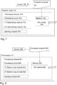
- FIG. 7 a schematic block diagram of embodiments of the network node 110 of Figure 1 is shown.
- the network node 110 may comprise a processing module 701, such as a means, one or more hardware modules and/or one or more software modules for performing the methods described herein.
- a processing module 701 such as a means, one or more hardware modules and/or one or more software modules for performing the methods described herein.
- the network node 110 may further comprise a memory 702.
- the memory may comprise, such as contain or store, a computer program 703.
- the processing module 701 comprises, e.g. 'is embodied in the form of' or 'realized by', a processing circuit 704 as an exemplifying hardware module.
- the memory 702 may comprise the computer program 703, comprising computer readable code units executable by the processing circuit 704, whereby the network node 110 is operative to perform the methods of Figure 5 .
- the computer readable code units cause the network node 110 to perform the method according to Figure 5 when the computer readable code units are executed by the network node 110.
- Figure 7 further illustrates a carrier 705 , or program carrier, which comprises the computer program 703 as described directly above.
- the processing module 701 comprises an Input/Output module 706, which may be exemplified by a receiving module and/or a sending module as described below when applicable.
- the processing module 701 may comprise one or more of a first determining module 710, a second determining module 720, and a sending module 730 as exemplifying hardware modules.
- a first determining module 710 a second determining module 720
- a sending module 730 a sending module 730 as exemplifying hardware modules.
- one or more of the aforementioned exemplifying hardware modules may be implemented as one or more software modules.
- the network node 110 is configured for managing a transmission power parameter indicating power of transmission to be sent on at least one D2D link 120 between the first device 111 and the second device 112.
- the network node 110 may be the second device 112.
- the network node 110 and/or the processing module 701 and/or the first determining module 710 is configured for determining a load relating to D2D communication between at least the first and second devices 111, 112.
- the network node 110 and/or the processing module 701 and/or the second determining module 720 is/are configured for determining the transmission power parameter based on the load.
- the network node 110 and/or the processing module 701 and/or the sending module 730 is/are configured for sending, to at least the first device 111, the transmission power parameter.
- the network node 110 and/or the processing module 701 and/or the second determining module 720, or a further determining module (not shown), are configured for determining the transmission power parameter by determining the transmission power parameter based on the load in an at least partly inverse manner while not exceeding a maximum transmit power of the first device 111.
- the network node 110 and/or the processing module 701 and/or the first determining module 710 may be configured for determining the load based on at least one of:
- FIG. 8 a schematic block diagram of embodiments of the first device 111 of Figure 1 is shown.
- the first device 111 may comprise a processing module 801 , such as a means, one or more hardware modules and/or one or more software modules for performing the methods described herein.
- a processing module 801 such as a means, one or more hardware modules and/or one or more software modules for performing the methods described herein.
- the first device 111 may further comprise a memory 802.
- the memory may comprise, such as contain or store, a computer program 803.
- the processing module 801 comprises, e.g. 'is embodied in the form of' or 'realized by', a processing circuit 804 as an exemplifying hardware module.
- the memory 802 may comprise the computer program 803, comprising computer readable code units executable by the processing circuit 804, whereby the first device 111 is operative to perform the methods of Figure 5 .
- the computer readable code units cause the first device 111 to perform the method according to Figure 5 when the computer readable code units are executed by the first device 111.
- Figure 8 further illustrates a carrier 805, or program carrier, which comprises the computer program 803 as described directly above.
- the processing module 801 comprises an Input/Output module 806, which may be exemplified by a receiving module and/or a sending module as described below when applicable.
- the processing module 801 may comprise one or more of a first determining module 810, a second determining module 820, and a sending module 830 as exemplifying hardware modules.
- a first determining module 810 a second determining module 820
- a sending module 830 a sending module 830 as exemplifying hardware modules.
- one or more of the aforementioned exemplifying hardware modules may be implemented as one or more software modules.
- the first device 111 is configured for managing a transmission power parameter indicating power of transmission to be sent on at least one D2D link 120 between the first device 111 and the second device 112. It shall be understood that the first device 111 may send the transmission in some embodiments, but in some other embodiments the first device 111 may receive the transmission.
- the first device 111 and/or the processing module 801 and/or the first determining module 810 is/are configured for determining a load relating to D2D communication between at least the first and second devices 111, 112.
- the first device 111 and/or the processing module 801 and/or the second determining module 820 is/are configured for determining the transmission power parameter based on the load.
- the first device 111 when the first device 111 receives the transmission on said at least one D2D link, the first device 111 and/or the processing module 801 and/or the sending module 830 is/are configured for sending, to the second device (112), the transmission power parameter.
- the first device 111 and/or the processing module 801 and/or the second determining module 820 is/are configured for determining the transmission power parameter by determining the transmission power parameter based on the load in an at least partly inverse manner while not exceeding a maximum transmit power of the first device 111.
- the first device (111) and/or the processing module 801 and/or the first determining module 810 are configured to determine the load based on at least one of:
- the term "node”, or “network node”, may refer to one or more physical entities, such as devices, apparatuses, computers, servers or the like. This may mean that embodiments herein may be implemented in one physical entity. Alternatively, the embodiments herein may be implemented in a plurality of physical entities, such as an arrangement comprising said one or more physical entities, i.e. the embodiments may be implemented in a distributed manner, such as on a set of server machines of a cloud system. In particular, in some examples of the method herein, the network node refers to the first or second device 111, 112.
- unit may refer to one or more functional units, each of which may be implemented as one or more hardware modules and/or one or more software modules in a node.
- program carrier may refer to one of an electronic signal, an optical signal, a radio signal, and a computer readable medium.
- the program carrier may exclude transitory, propagating signals, such as the electronic, optical and/or radio signal.
- the carrier may be a non-transitory carrier, such as a non-transitory computer readable medium.
- processing module may include one or more hardware modules, one or more software modules or a combination thereof. Any such module, be it a hardware, software or a combined hardware-software module, may be a determining means, estimating means, capturing means, associating means, comparing means, identification means, selecting means, receiving means, sending means or the like as disclosed herein.
- the expression “means” may be a module corresponding to the modules listed above in conjunction with the Figures.
- software module may refer to a software application, a Dynamic Link Library (DLL), a software component, a software object, an object according to Component Object Model (COM), a software component, a software function, a software engine, an executable binary software file or the like.
- DLL Dynamic Link Library
- COM Component Object Model
- processing circuit may refer to a processing unit, a processor, an Application Specific integrated Circuit (ASIC), a Field-Programmable Gate Array (FPGA) or the like.
- the processing circuit or the like may comprise one or more processor kernels.
- the expression “configured to/for” may mean that a processing circuit is configured to, such as adapted to or operative to, by means of software configuration and/or hardware configuration, perform one or more of the actions described herein.
- action may refer to an action, a step, an operation, a response, a reaction, an activity or the like. It shall be noted that an action herein may be split into two or more sub-actions as applicable. Moreover, also as applicable, it shall be noted that two or more of the actions described herein may be merged into a single action.
- memory may refer to a hard disk, a magnetic storage medium, a portable computer diskette or disc, flash memory, random access memory (RAM) or the like. Furthermore, the term “memory” may refer to an internal register memory of a processor or the like.
- the term "computer readable medium” may be a Universal Serial Bus (USB) memory, a DVD-disc, a Blu-ray disc, a software module that is received as a stream of data, a Flash memory, a hard drive, a memory card, such as a MemoryStick, a Multimedia Card (MMC), Secure Digital (SD) card, etc.
- USB Universal Serial Bus
- MMC Multimedia Card
- SD Secure Digital
- computer readable code units may be text of a computer program, parts of or an entire binary file representing a computer program in a compiled format or anything there between.
- radio resource may refer to a certain coding of a signal and/or a time frame and/or a frequency range in which the signal is transmitted.
- a resource may refer to one or more Physical Resource Blocks (PRB) which is used when transmitting the signal.
- PRB Physical Resource Blocks
- a PRB may be in the form of Orthogonal Frequency Division Multiplexing (OFDM) PHY resource blocks (PRB).
- OFDM Orthogonal Frequency Division Multiplexing
- PRB Physical resource block
- Physical resource block is known from 3GPP terminology relating to e.g. Long Term Evolution Systems.
- the expression “transmit” and “send” are considered to be interchangeable. These expressions include transmission by broadcasting, uni-casting, group-casting and the like. In this context, a transmission by broadcasting may be received and decoded by any authorized device within range. In case of uni-casting, one specifically addressed device may receive and encode the transmission. In case of group-casting, a group of specifically addressed devices may receive and decode the transmission.
- number and/or value may be any kind of digit, such as binary, real, imaginary or rational number or the like. Moreover, “number” and/or “value” may be one or more characters, such as a letter or a string of letters. “Number” and/or “value” may also be represented by a bit string.
- a set of may refer to one or more of something.
- a set of devices may refer to one or more devices
- a set of parameters may refer to one or more parameters or the like according to the embodiments herein.
- the common abbreviation "e.g.” which derives from the Latin phrase “exempli gratia,” may be used to introduce or specify a general example or examples of a previously mentioned item, and is not intended to be limiting of such item. If used herein, the common abbreviation “i.e.”, which derives from the Latin phrase “id est,” may be used to specify a particular item from a more general recitation.
- the common abbreviation “etc.”, which derives from the Latin expression “et cetera” meaning “and other things” or “and so on” may have been used herein to indicate that further features, similar to the ones that have just been enumerated, exist.
Description
- Embodiments herein relate to wireless communication systems, such as mixed cellular and Device-To-Device (D2D) systems. In particular, a method and a network node for managing a transmission power parameter indicating power of transmission to be sent on at least one D2D link between a first device and a second device are disclosed. Corresponding computer programs and carriers therefor are also disclosed.
- A mixed cellular and D2D system allows devices to directly exchange information with each other, i.e. without passing through a base station and a core network as is common with conventional cellular communication systems. An exemplifying mixed cellular and D2D system, e.g. featuring D2D Proximity Services (D2D ProSe), was introduced with Release-12 (Rel-12) of Long Term Evolution (LTE) of the Third Generation Partnership Project (3GPP). With D2D ProSe, two main services for D2D communication are provided; a direct communication service and a direct discovery service.
- With the direct communication service, the devices establish a direct user plane connection. The direct communication service primarily includes voice, such as Voice over Internet Protocol (VoIP), and file transfer, such as file transfer over File Transfer Protocol (FTP). With the direct discovery service, the devices transmit and monitor signals that enable them to be aware of proximity to another device or other devices.
- Use cases for D2D ProSe include both Public Safety (PS) and commercial use.
- In the PS applications, the direct communication service provides basic VoIP connectivity to other devices, independently of cellular coverage, such as LTE coverage, for the devices. Moreover, the direct discovery service may provide functions for detection of presence of peer devices, e.g. based on their professions or the like. Typically, in an emergency situation, it would be beneficial to easily find out if there is any doctor and/or nurse nearby.
- In the commercial applications, the direct communication service provides simple push-to-talk functions, where communication typically is be one-to-many. Furthermore, the direct discovery service can broadcast advertisements, such as "pizza for 5$", etc.
- In a known mixed cellular and D2D system according to 3GPP Rel-12, a user transmission is sent from a sender device to a receiver device at a specific transmission power for D2D transmissions, i.e. D2D transmissions on so called D2D links between e.g. the sender device and the receiver device.
- For cellular transmissions in an LTE system, it is known to set the transmission power according to the following formula:

- Pmax: Maximum power allowed by the transmission in for uplink. It depends on the UE category,
- M: The number of allocated Physical Resource Blocks (PRBs) per user,
- Po: The power to be contained in one PRB. It is cell specific parameter and measured in dBm/PRB,
- α: Path loss compensation factor. It is a cell specific parameter in the range [0 1],
- PL: Estimated uplink path loss at the UE,
- δmcs : MCS dependent offset. It is UE specific, and
- f(Δ i ): closed loop correction function.
- However, this formula does not efficiently set the transmission power for D2D transmissions. Typically, the transmission power for D2D transmissions are set to a constant value below an upper power limit, which depends on pathloss. Hence, a disadvantage is that it may be difficult to set the transmission power for D2D links such that improved D2D communication may be achieved.
-
US 2011 /243010 A1 teaches techniques for performing interference management to support peer to peer communication in a wide area network. In one example a transmitting node may set its transmit power level such that the target load levels for all interfered nodes can be achieved given the channel gains between the transmitting node and the interfered nodes. - In
US 2013/157676 A1 a control method for device-to-device (D2D) communication is described. A base station measures a load of a cell, receives location information about each piece of user equipment (UE) from a plurality of pieces of UE, selects any one of an overlay-based resource allocation method and an underlay- based resource allocation method on the basis of the measured cell load and the location information about the respective pieces of UE, allocates resources for D2D communication on the basis of the selected resource allocation method, and controls power according to the locations of the pieces of UE and a density of pieces of cellular communication UE. -
WO 2010/049801 A1 describes an apparatus, system and method to dynamically manage an allocation of communication resources for direct device-to-device communications between a plurality of wireless communication devices in a wireless communication system. In one embodiment, the apparatus includes a communication resource allocator configured to: (I) select a master communication device of a plurality of wireless communication devices that form a device-to-device group, (2) provide an allocation of communication resources for device-to-device group that facilitate direct device-to-device communications therebetween. The apparatus also includes a message generator configured to assemble messages that include the allocation of the communication resources. - An object may be to improve performance of the above mentioned mixed cellular and D2D system.
- The object of the present invention is achieved in accordance with the attached claims.
- The network node may set the transmission power parameter differently depending on the load. For example, the network node may increase the transmission power parameter, i.e. allow a high transmission power, when the load is low, in order to improve transmission efficiency. However, as another example, the network node may decrease the transmission power parameter, when the load is high, in order to improve transmission efficiency. High and low may be determined in relation to a high threshold value and a low threshold value, respectively. In the latter example, the transmission efficiency is improved due to that transmission power of in-band emission is reduced. As a result, less interference towards neighboring devices is generated.
- Moreover, an advantage is that power consumption of the first device may be reduced, when the transmission power parameter is decreased. Hence, a so called battery-life of a battery of the first device may be extended.
- Furthermore, an advantage is that dropping of services, such as calls, may be reduced, when the transmission power parameter is increased.
- Moreover, it shall be noted that the setting of the transmission power has effect on a transmission power level for upcoming transmissions, i.e. the transmission power parameter more or less immediately affects the transmission power of in-band emission.
- The various aspects of embodiments disclosed herein, including particular features and advantages thereof, will be readily understood from the following detailed description and the accompanying drawings, in which:
-
Figure 1 is a schematic overview of an exemplifying system in which embodiments herein may be implemented, -
Figure 2 is a diagram illustrating discovered neighbors as a function of transmission power, -
Figure 3 is a diagram illustrating Signal-To-Interference-and-Noise Ratio (SINR) as a function of transmission power, -
Figure 4 is another diagram illustrating SINR as a function of transmission power, -
Figure 5 is a flowchart illustrating embodiments of the method, -
Figure 6 is a diagram illustrating an exemplifying function of transmission power versus load, -
Figure 7 is a block diagram illustrating embodiments of the network node, and -
Figure 8 is a block diagram illustrating embodiments of the first device. - Throughout the following description similar reference numerals have been used to denote similar features, such as nodes, actions, steps, modules, circuits, parts, items elements, units or the like, when applicable. In the Figures, features that appear in some embodiments are indicated by dashed lines.
-
Figure 1 depicts an exemplifying mixed cellular andD2D system 100 in which embodiments herein may be implemented. In this example, thesystem 100 is a LTE system, e.g. Rel-12 or higher. In this context, a higher release is subsequent in time to Rel-12. - In other examples, the mixed cellular and
D2D system 100 may be any cellular or wireless communication system, such as a Universal Mobile Telecommunication System (UMTS), Global System for Mobile communication (GSM) and Worldwide Interoperability for Microwave Access (WiMAX) allowing a layer of D2D communications or the like. - The mixed cellular and
D2D system 100 comprises anetwork node 110, such as a radio network node, an evolved-Node B (eNB), a base station, a relay, a repeater, a radio remote unit a Base Station System (BSS), a Radio Network Controller (RNC), a Radio Base Station (RBS), a control node controlling one or more Remote Radio Units (RRUs), an access point and the like. -
Figure 1 further illustrates afirst device 111 and asecond device 112. In some examples, the first andsecond devices network node 110. This means that the first andsecond devices 111 are present in the mixedcellular D2D system 100. In other examples, the first and/orsecond devices network node 110. - The first and
second devices first device 111 sends user transmission to thesecond device 112. Thesecond device 112 may then send control transmission to thefirst device 111. - As used herein, the term "device" may refer to a wireless communication device, a user equipment, a machine-to-machine (M2M) device, a mobile phone, a cellular phone, a Personal Digital Assistant (PDA) equipped with radio communication capabilities, a smartphone, a laptop or personal computer (PC) equipped with an internal or external mobile broadband modem, a tablet PC with radio communication capabilities, a portable electronic radio communication device, a sensor device equipped with radio communication capabilities or the like. The sensor may be any kind of weather sensor, such as wind, temperature, air pressure, humidity etc. As further examples, the sensor may be a light sensor, an electronic or electric switch, a microphone, a loudspeaker, a camera sensor etc. The term "user" may indirectly refer to the wireless device. Sometimes, the term "user" may be used to refer to the user equipment or the like as above. It shall be understood that the user may not necessarily involve a human user. The term "user" may also refer to a machine, a software component or the like using certain functions, methods and similar.
- The
network node 110 may communicate 121, 122 with the first andsecond devices - In order to better appreciate the benefits and advantages of the embodiments herein, the following observations are made.
-
Figure 2 illustrates principal graphs as conclusion when targeting to analyze D2D performance with respect to transmission power for D2D transmissions. InFigures 2 ,3 and 4 , simulations with 75 D2D capable UEs per cell and 5 FTP UEs having uploading and downloading traffic per cell are illustrated. Notable, values of D2D transmission power are purely schematic. For example, along the x-axis inFigures 2-4 , values 1-4 may correspond to a power of 'a' watts (W) to '4*a' W, where 'a' may be equal to 125 mW (21 dBm), 200 mW (23 dBm), 500 mW (27 dBm) or the like. - In
Figure 2 , mean number of discovered neighbors is plotted as a function of D2D transmission power for four different scenarios. - In a first scenario "D2D, 10s (20%)", only 20% of the 75 D2D capable UEs are involved in D2D communication with some other of the 75 D2D capable UEs. In this scenario, D2D load may be said to be low.
- In a second scenario "D2D, 10s (50%)", 50% of the 75 D2D capable UEs are involved in D2D communication. In this scenario, D2D load may be said to be medium.
- In a third scenario "D2D, 10s (100%)", 100% of the 75 D2D capable UEs are involved in D2D communication. In this scenario, D2D load may be said to be high.
- In a fourth scenario "5 FTP users, D2D, 10s (100%)", 100% of the 75 D2D capable UEs are involved in D2D communication and 5 UEs are involved in cellular communication due to FTP uploading and downloading. In this scenario, D2D load may of course be said to be high as well.
- From
Figure 2 , it can be seen that in the first scenario, with low D2D load, better D2D discovery performance is observed as compared to the other scenarios. Here better D2D discovery performance means that a greater mean number of discovered neighbors are observed, i.e. more neighbors can successfully receive the discovery message. As the D2D transmission power increases, the mean number of discovered neighbors increases. In contrast thereto, as an extreme among these scenarios, it can been seen that, for the fourth scenario with high D2D load, worse D2D discovery performance is observed as compared to the other scenarios. Moreover, as the D2D transmission power increases, the mean number of discovered neighbors decreases. In the fourth scenario, higher D2D transmission power cannot improve the performance due to higher interference. The interference is mainly caused by the power in-band emission from neighboring devices. -
Figure 3 illustrates Signal-To-Interference-and-Noise Ratio (SINR) as a function of D2D transmission power for the four scenarios described above in connection withFigure 2 . FromFigure 3 , it can be seen that decrease in SINR is mainly dependent on D2D load, i.e. portion of D2D devices that are involved in D2D communication. A reason to this is that a first difference in SINR for the third and fourth scenarios is much less than a second difference in SINR for the second and third scenarios, or a third difference in SINR for the first and second scenarios. - Moreover, now turning to
Figure 4 , SINR as a function of number of D2D transmission power is illustrated. In this Figure, two scenarios with and without consideration of power In-Band Emission (IBE) are illustrated. In this context, power IBE refers to transmission power within time/frequency resource assigned to D2D communication. From the Figure, it is observed that power in-band emission from neighboring devices results in a high drop of the SINR. -
Figure 5 illustrates an exemplifying method according to embodiments herein when implemented in thesystem 100 ofFigure 1 . As an example, thenetwork node 110 performs a method for managing a transmission power parameter indicating power of transmission to be sent on at least oneD2D link 120 between thefirst device 111 and thesecond device 112. Said at least one D2D link may typically carry user transmissions from thefirst device 111 to thesecond device 112. - In other examples the method may be performed by the
second device 112. In these examples, said at least one D2D link may additionally carry control transmissions from thesecond device 112 to thefirst device 111. In yet further examples, the method is performed by thefirst device 111. In these examples, thefirst device 111 autonomously determines the transmission power parameter to be applied for the transmissions to thesecond device 112. - For simplicity, the method is described in the following with reference to when the
network node 110 performs the method. - One or more of the following actions may be performed in any suitable order.
- The
network node 110 determines a load relating to D2D communication between at least the first andsecond devices network node 110 obtains the load to be used in action A020 below. - In case of an OOC scenario, it may be that the at least one D2D link is only a particular D2D link between the first and
second devices second device 112 may determine the load based on only the particular D2D link. - However, when the
network node 110 performs action A010, the at least one D2D link may be a plurality of D2D links, or even all D2D links managed by thenetwork node 110. This means that thenetwork node 110 may determine the load while taking a plurality D2D links into account. - The load may be determined as exemplified in section "Determining load".
- Subsequently to action A010, the
network node 110 determines the transmission power parameter based on the load. - The
network node 110 determines the transmission power parameter based on the load in an at least partly inverse manner while not exceeding a maximum transmit power of thefirst device 111. In more detail, transmission power parameter may be determined by a function that is, in some range, inversely proportional to the load. Expressed somewhat differently, the determining A020 of the transmission power parameter comprises determining the transmission power parameter based on the load in an at least partly inverse manner, such as an at least partly proportionally inverse manner. - Since open loop power control for compensating the uplink cellular path loss has been defined in 3GPP Rel-12 for D2D transmission, the formula mentioned in the background section may be updated as (while keeping the notation of the formula from the background section):

- According to embodiments herein, the load relating to D2D communication is considered when determining the transmission power parameter for D2D transmissions. A higher portion of the maximum transmission power can be used for D2D transmission. While a lower portion of maximum transmission power shall be applied. Accordingly, the formula (2) can be further updated as

- β: D2D load compensation factor. It is a cell specific parameter in the range [0 1],
- LoadD2D : Estimated D2D load, it is a cell specific measurement, and
- k: is a constant.
- The value range of Ptx may be pre-defined according to the transmission power range. As an example, β multiplied by k equals an upper limit for a part contributing to D2D transmission, i.e.
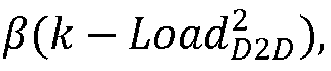
Figure 6 illustrates the part compensating for D2D transmission. - As an example, the transmission power parameter may have three pre-set levels, such as a first, a second and a third transmission power parameter value. Exemplifying values of the first, second and third transmission power parameter may be 125 mW (milliWatts) (21 dBm), 200 mW (23 dBm), and 500 mW (27 dBm). Additionally, there may be two threshold values, such as a high threshold and a low threshold for the load relating to the D2D communication. The
network node 110 may then set the transmission power parameter to the first transmission power parameter value when the load is greater than the high threshold. Should the load be less than the low threshold, thenetwork node 110 may set the transmission power parameter to the third transmission power parameter value. In other cases, when the load is between the low and high threshold, thenetwork node 110 may set the transmission power parameter to the second transmission power parameter value. - Other exemplifying formulas may be found, while still applying a principle of reducing the transmission power parameter, in at least one range, when the load is high, where high may be seen relative to a high threshold value.
- The
network node 110 may send, to at least thefirst device 111, the transmission power parameter. - In Action A030, the
network node 110 may signal to at least one of the first andsecond devices second devices 111, 112: either by System Information Block (SIB) signalling or by dedicated signalling. - The SIB signalling, on the one hand, is suitable if the transmission power parameter is applicable to all devices, such as the first and
second devices network node 110. - The dedicated signalling, on the other hand, may provide additional flexibility if the determined transmission power parameter is applicable only to specific devices, such as the first or
second device - Both SIB signalling and dedicated signalling may be applied in combination in some examples.
- When the
second device 112 is out-of-coverage, the transmission power parameter may be received on the Physical Sidelink Broadcast Channel (PSBCH), which is broadcasted by thefirst device 111 still within coverage. - As an exemplifying further signalling alternative, the
network node 110 may pre-configure multiple configurations, i.e. pre-configured transmission power parameters, which are applicable to different load scenarios. The different load scenarios may be identified by the low and/or high thresholds described above. The first andsecond devices system 100, or at some other time. In this example, thenetwork node 110 does not need to send the transmission power parameter when the load varies. Instead, it will be up to the device, e.g. thefirst device 110, to choose an appropriate transmission power parameter among the pre-configured transmission power parameters by itself. - The devices, neighbouring to the
first device 111, may become aware of the transmission power parameter currently applied in various manners. - The
first device 111 may send the transmission power parameter configuration to the neighbouring devices via a D2D control channel, such as Physical Sidelink Control Channel (PSCCH). Alternatively, or even additionally, thefirst device 111 may include the transmission power parameter in a Medium Access Control (MAC) element of a MAC Packet Data Unit (PDU). - The MAC element may be configured as shown below:
Group Index LCG ID Configuration ID - Group index: The group index field identifies the ProSe (Proximity based Services) Destination. The group is typically composed of devices, such as the first and
second device - LCG ID: The Logical Channel Group (LCG) ID field identifies the group of logical channel(s) which buffer status is being reported.
- Configuration ID identifies which configuration to apply according to the signalling The
second device 112 may be informed about the transmission power parameter in advance of the transmission thanks to that thefirst device 111 may perform the following actions: - 1. The
first device 111 may transmit, to thesecond device 112, the transmission power parameter to be used in subsequent transmissions. The transmission power parameter may then be included in the MAC element in a separate MAC PDU packet. - 2. Next, the
first device 111 may transmit data packets while applying the received, from thenetwork node 110 as in action A030, transmission power parameter. -
Step 1 may preferably only be executed once during a given period since the transmission power parameter should be static for during the given period.Step 2 is executed in a sub-frame that is different from the sub-frame in which step 1 is executed. Hence, thesecond device 112 may receive the transmission power parameter and a user data transmission in sequential sub-frames. - Now elaborating on how the load may be determined. The
network node 110, or thesecond device 112, may determine the load based on at least one of: - a number of physical resource blocks used for the D2D communication,
- a number of sub-frames occupied by the D2D communication,
- a number of devices involved in the D2D communication,
- statistics concerning decoding of D2D physical channels of the D2D communication,
- received power per packet of the D2D communication,
- a delay of D2D discovery,
- a delay of D2D transmissions in the D2D communication,
- a percentage of neighboring devices, being neighbors to at least one of the
first device 111 and thesecond device 112, which neighboring devices are capable of successfully receiving one D2D packet within one transmission period, and - the like.
- The number of physical resources blocks may indicate the load, since when a great number of physical resource blocks are used for D2D communication a lot of information may be transferred over the D2D link.
- The number of sub-frames occupied by the D2D communication may indicate the load, since when a great number of sub-frames are used for D2D communication a lot of information may be transferred over the D2D link.
- The number of devices involved in the D2D communication may indicate the load, since for an average transmission activity among the number of devices, the load will increase for an increased number of devices involved in the D2D communication.
- The statistics concerning decoding of D2D physical channels of the D2D communication may indicate the load, since when decoding is not successful, it may be a sign of that interference towards said at least one D2D link is too high. As described above in relation to
Figure 3 and/orFigure 4 , such unsuccessful decoding will primarily be dependent on amount of D2D device involved in the D2D communication. Hence, when the load is high, the decoding statistics will indicate many unsuccessful decodings. - The delay of D2D discovery may indicate the load, since if the delay is high, the load is expected to be high due to that many retransmission attempts of the discovery signaling is required. Many retransmission attempts do, in turn, cause a high delay.
- The received power per packet of the D2D communication may indicate the load according to similar reasoning as above.
- The delay of D2D transmissions in the D2D communication may indicate the load according to similar reasoning as above.
- The percentage of devices, being neighbors to the
first device 111, which devices are capable of successfully receiving one D2D packet within one transmission period may indicate the load according to similar reasoning as above. - The metrics above indicate how good the D2D performance is. So, the better performance might indicate that the system load is low, while worse performance might indicate that the system load is higher. The above metrics may be combined to provide a better evaluation of the system load. A single metric might not provide as accurate results.
- In a further example, an amount of resources used for D2D communication is adjusted based on the load relating to D2D transmission. Hence, when the load is high a greater number of resources is assigned, or reserved, for D2D transmission as compared to when the load is low. Again, "high" and/or "low" may be related to the respective one of the high and low threshold value mentioned above. The resources may refer to number of subframes, physical resource blocks, channels, D2D transmission periodicity or the like, which may be reserved for D2D communication. The D2D transmission periodicity may indicate a so called discovery period.
- In a particular embodiment, the method above is performed by the
first device 111. In this embodiment, action A030 is not performed. Instead, thefirst device 111 applies the transmission power parameter in subsequent subframes. This means that thefirst device 111 will begin to send transmissions according to the determined transmission power parameter. - With reference to
Figure 7 , a schematic block diagram of embodiments of thenetwork node 110 ofFigure 1 is shown. - The
network node 110 may comprise aprocessing module 701, such as a means, one or more hardware modules and/or one or more software modules for performing the methods described herein. - The
network node 110 may further comprise amemory 702. The memory may comprise, such as contain or store, acomputer program 703. - According to some embodiments herein, the
processing module 701 comprises, e.g. 'is embodied in the form of' or 'realized by', aprocessing circuit 704 as an exemplifying hardware module. In these embodiments, thememory 702 may comprise thecomputer program 703, comprising computer readable code units executable by theprocessing circuit 704, whereby thenetwork node 110 is operative to perform the methods ofFigure 5 . - In some other embodiments, the computer readable code units cause the
network node 110 to perform the method according toFigure 5 when the computer readable code units are executed by thenetwork node 110. -
Figure 7 further illustrates acarrier 705, or program carrier, which comprises thecomputer program 703 as described directly above. - In some embodiments, the
processing module 701 comprises an Input/Output module 706, which may be exemplified by a receiving module and/or a sending module as described below when applicable. - In further embodiments, the
processing module 701 may comprise one or more of a first determiningmodule 710, a second determiningmodule 720, and a sendingmodule 730 as exemplifying hardware modules. In other examples, one or more of the aforementioned exemplifying hardware modules may be implemented as one or more software modules. - Accordingly, the
network node 110 is configured for managing a transmission power parameter indicating power of transmission to be sent on at least oneD2D link 120 between thefirst device 111 and thesecond device 112. Thenetwork node 110 may be thesecond device 112. - Therefore, according to the various embodiments described above, the
network node 110 and/or theprocessing module 701 and/or the first determiningmodule 710 is configured for determining a load relating to D2D communication between at least the first andsecond devices - The
network node 110 and/or theprocessing module 701 and/or the second determiningmodule 720 is/are configured for determining the transmission power parameter based on the load. - Moreover, the
network node 110 and/or theprocessing module 701 and/or the sendingmodule 730 is/are configured for sending, to at least thefirst device 111, the transmission power parameter. - In some embodiments, the
network node 110 and/or theprocessing module 701 and/or the second determiningmodule 720, or a further determining module (not shown), are configured for determining the transmission power parameter by determining the transmission power parameter based on the load in an at least partly inverse manner while not exceeding a maximum transmit power of thefirst device 111. - The
network node 110 and/or theprocessing module 701 and/or the first determiningmodule 710 may be configured for determining the load based on at least one of: - a number of physical resource blocks used for the D2D communication,
- a number of sub-frames occupied by the D2D communication,
- a number of devices involved in the D2D communication,
- statistics concerning decoding of D2D physical channels of the D2D communication,
- received power per packet of the D2D communication,
- a delay of D2D discovery,
- a delay of D2D transmissions in the D2D communication,
- a percentage of neighboring devices, being neighbors to at least one of the
first device 111 and thesecond device 112, which neighboring devices are capable of successfully receiving one D2D packet within one transmission period, and the like. - With reference to
Figure 8 , a schematic block diagram of embodiments of thefirst device 111 ofFigure 1 is shown. - The
first device 111 may comprise aprocessing module 801, such as a means, one or more hardware modules and/or one or more software modules for performing the methods described herein. - The
first device 111 may further comprise amemory 802. The memory may comprise, such as contain or store, acomputer program 803. - According to some embodiments herein, the
processing module 801 comprises, e.g. 'is embodied in the form of' or 'realized by', aprocessing circuit 804 as an exemplifying hardware module. In these embodiments, thememory 802 may comprise thecomputer program 803, comprising computer readable code units executable by theprocessing circuit 804, whereby thefirst device 111 is operative to perform the methods ofFigure 5 . - In some other embodiments, the computer readable code units cause the
first device 111 to perform the method according toFigure 5 when the computer readable code units are executed by thefirst device 111. -
Figure 8 further illustrates acarrier 805, or program carrier, which comprises thecomputer program 803 as described directly above. - In some embodiments, the
processing module 801 comprises an Input/Output module 806, which may be exemplified by a receiving module and/or a sending module as described below when applicable. - In further embodiments, the
processing module 801 may comprise one or more of a first determiningmodule 810, a second determiningmodule 820, and a sendingmodule 830 as exemplifying hardware modules. In other examples, one or more of the aforementioned exemplifying hardware modules may be implemented as one or more software modules. - Accordingly, the
first device 111 is configured for managing a transmission power parameter indicating power of transmission to be sent on at least oneD2D link 120 between thefirst device 111 and thesecond device 112. It shall be understood that thefirst device 111 may send the transmission in some embodiments, but in some other embodiments thefirst device 111 may receive the transmission. - Therefore, according to the various embodiments described above, the
first device 111 and/or theprocessing module 801 and/or the first determiningmodule 810 is/are configured for determining a load relating to D2D communication between at least the first andsecond devices - Moreover, the
first device 111 and/or theprocessing module 801 and/or the second determiningmodule 820 is/are configured for determining the transmission power parameter based on the load. - In some embodiments, when the
first device 111 receives the transmission on said at least one D2D link, thefirst device 111 and/or theprocessing module 801 and/or the sendingmodule 830 is/are configured for sending, to the second device (112), the transmission power parameter. - In some embodiments, the
first device 111 and/or theprocessing module 801 and/or the second determiningmodule 820 is/are configured for determining the transmission power parameter by determining the transmission power parameter based on the load in an at least partly inverse manner while not exceeding a maximum transmit power of thefirst device 111. - The first device (111) and/or the
processing module 801 and/or the first determiningmodule 810 are configured to determine the load based on at least one of: - a number of physical resource blocks used for the D2D communication,
- a number of sub-frames occupied by the D2D communication,
- a number of devices involved in the D2D communication,
- statistics concerning decoding of D2D physical channels of the D2D communication,
- received power per packet of the D2D communication,
- a delay of D2D discovery,
- a delay of D2D transmissions in the D2D communication, and
- a percentage of neighboring devices, being neighbors to at least one of the first device (111) and the second device (112), which neighboring devices are capable of successfully receiving one D2D packet within one transmission period.
- As used herein, the term "node", or "network node", may refer to one or more physical entities, such as devices, apparatuses, computers, servers or the like. This may mean that embodiments herein may be implemented in one physical entity. Alternatively, the embodiments herein may be implemented in a plurality of physical entities, such as an arrangement comprising said one or more physical entities, i.e. the embodiments may be implemented in a distributed manner, such as on a set of server machines of a cloud system. In particular, in some examples of the method herein, the network node refers to the first or
second device - As used herein, the term "unit" may refer to one or more functional units, each of which may be implemented as one or more hardware modules and/or one or more software modules in a node.
- As used herein, the term "program carrier" may refer to one of an electronic signal, an optical signal, a radio signal, and a computer readable medium. In some examples, the program carrier may exclude transitory, propagating signals, such as the electronic, optical and/or radio signal. Thus, in these examples, the carrier may be a non-transitory carrier, such as a non-transitory computer readable medium.
- As used herein, the term "processing module" may include one or more hardware modules, one or more software modules or a combination thereof. Any such module, be it a hardware, software or a combined hardware-software module, may be a determining means, estimating means, capturing means, associating means, comparing means, identification means, selecting means, receiving means, sending means or the like as disclosed herein. As an example, the expression "means" may be a module corresponding to the modules listed above in conjunction with the Figures.
- As used herein, the term "software module" may refer to a software application, a Dynamic Link Library (DLL), a software component, a software object, an object according to Component Object Model (COM), a software component, a software function, a software engine, an executable binary software file or the like.
- As used herein, the term "processing circuit" may refer to a processing unit, a processor, an Application Specific integrated Circuit (ASIC), a Field-Programmable Gate Array (FPGA) or the like. The processing circuit or the like may comprise one or more processor kernels.
- As used herein, the expression "configured to/for" may mean that a processing circuit is configured to, such as adapted to or operative to, by means of software configuration and/or hardware configuration, perform one or more of the actions described herein.
- As used herein, the term "action" may refer to an action, a step, an operation, a response, a reaction, an activity or the like. It shall be noted that an action herein may be split into two or more sub-actions as applicable. Moreover, also as applicable, it shall be noted that two or more of the actions described herein may be merged into a single action.
- As used herein, the term "memory" may refer to a hard disk, a magnetic storage medium, a portable computer diskette or disc, flash memory, random access memory (RAM) or the like. Furthermore, the term "memory" may refer to an internal register memory of a processor or the like.
- As used herein, the term "computer readable medium" may be a Universal Serial Bus (USB) memory, a DVD-disc, a Blu-ray disc, a software module that is received as a stream of data, a Flash memory, a hard drive, a memory card, such as a MemoryStick, a Multimedia Card (MMC), Secure Digital (SD) card, etc.
- As used herein, the term "computer readable code units" may be text of a computer program, parts of or an entire binary file representing a computer program in a compiled format or anything there between.
- As used herein, the term "radio resource" may refer to a certain coding of a signal and/or a time frame and/or a frequency range in which the signal is transmitted. In some examples, a resource may refer to one or more Physical Resource Blocks (PRB) which is used when transmitting the signal. In more detail, a PRB may be in the form of Orthogonal Frequency Division Multiplexing (OFDM) PHY resource blocks (PRB). The term "physical resource block" is known from 3GPP terminology relating to e.g. Long Term Evolution Systems.
- As used herein, the expression "transmit" and "send" are considered to be interchangeable. These expressions include transmission by broadcasting, uni-casting, group-casting and the like. In this context, a transmission by broadcasting may be received and decoded by any authorized device within range. In case of uni-casting, one specifically addressed device may receive and encode the transmission. In case of group-casting, a group of specifically addressed devices may receive and decode the transmission.
- As used herein, the terms "number" and/or "value" may be any kind of digit, such as binary, real, imaginary or rational number or the like. Moreover, "number" and/or "value" may be one or more characters, such as a letter or a string of letters. "Number" and/or "value" may also be represented by a bit string.
- As used herein, the term "set of" may refer to one or more of something. E.g. a set of devices may refer to one or more devices, a set of parameters may refer to one or more parameters or the like according to the embodiments herein.
- As used herein, the expression "in some embodiments" has been used to indicate that the features of the embodiment described may be combined with any other embodiment disclosed herein.
- Further, as used herein, the common abbreviation "e.g.", which derives from the Latin phrase "exempli gratia," may be used to introduce or specify a general example or examples of a previously mentioned item, and is not intended to be limiting of such item. If used herein, the common abbreviation "i.e.", which derives from the Latin phrase "id est," may be used to specify a particular item from a more general recitation. The common abbreviation "etc.", which derives from the Latin expression "et cetera" meaning "and other things" or "and so on" may have been used herein to indicate that further features, similar to the ones that have just been enumerated, exist.
- Even though embodiments of the various aspects have been described, many different alterations, modifications and the like thereof will become apparent for those skilled in the art. The described embodiments are therefore not intended to limit the scope of the present disclosure, which is defined by the appended claims only.
Claims (12)
- A method, performed by a first device, for managing a transmission power parameter indicating power for Device-To-Device, D2D, transmission to be sent on at least one D2D link (120) between the first device (111) and a second device (112), wherein the method comprises:determining (A010) a load based on one or more metric of a D2D communication between at least the first and second devices (111, 112), wherein the load corresponds to a usage of D2D communication resources; anddetermining (A020) the transmission power parameter based on the determined load, wherein the determining (A020) of the transmission power parameter comprises determining the transmission power parameter based on the load in an at least partly inverse manner while not exceeding a maximum transmit power of the first device (111).
- The method according to claim 1, wherein the method comprises sending (A030), to at least the second device (112), the transmission power parameter.
- The method according to any one of the preceding claims, wherein the determining (A010) of the load is based on at least one of:- a number of physical resource blocks used for the D2D communication,- a number of sub-frames occupied by the D2D communication,- a number of devices involved in the D2D communication,- statistics concerning decoding of D2D physical channels of the D2D communication,- received power per packet of the D2D communication,- a delay of D2D discovery,- a delay of D2D transmissions in the D2D communication, and- a percentage of neighboring devices, being neighbors to at least one of the first device (111) and the second device (112), which neighboring devices are capable of successfully receiving one D2D packet within one transmission period.
- A method, performed by a network node, for managing a transmission power parameter indicating power for Device-To-Device, D2D, transmission to be sent on at least one D2D link (120) between a first device (111) and a second device (112), wherein the method comprises:determining (A010) a load based on one or more metric of a D2D communication between at least the first and second devices (111, 112) wherein the load corresponds to a usage of D2D communication resources; anddetermining (A020) the transmission power parameter based on the load, wherein the determining (A020) of the transmission power parameter comprises determining the transmission power parameter based on the load in an at least partly inverse manner while not exceeding a maximum transmit power of the first device (111); andsending (A030), to at least one of the first device (111) and the second device (112), the transmission power parameter.
- The method according to claim 4, wherein the determining (A010) of the load is based on at least one of:- a number of physical resource blocks used for the D2D communication,- a number of sub-frames occupied by the D2D communication,- a number of devices involved in the D2D communication,- statistics concerning decoding of D2D physical channels of the D2D communication,- received power per packet of the D2D communication,- a delay of D2D discovery,- a delay of D2D transmissions in the D2D communication, and- a percentage of neighboring devices, being neighbors to at least one of the first device (111) and the second device (112), which neighboring devices are capable of successfully receiving one D2D packet within one transmission period.
- A network node (110) configured for managing a transmission power parameter indicating power for Device-To-Device, D2D, transmission to be sent on at least one D2D link (120) between a first device (111) and a second device (112), wherein the network node (110) is configured for:determining a load based on one or more metric of a D2D communication between at least the first and second devices (111, 112) wherein the load corresponds to a usage of D2D communication resources;determining the transmission power parameter based on the load, wherein the determining (A020) of the transmission power parameter comprises determining the transmission power parameter based on the load in an at least partly inverse manner while not exceeding a maximum transmit power of the first device (111); andsending, to at least the first device (111), the transmission power parameter.
- The network node (110) according to claim 6, wherein the network node (110) is configured for determining the load based on at least one of:- a number of physical resource blocks used for the D2D communication,- a number of sub-frames occupied by the D2D communication,- a number of devices involved in the D2D communication,- statistics concerning decoding of D2D physical channels of the D2D communication,- received power per packet of the D2D communication,- a delay of D2D discovery,- a delay of D2D transmissions in the D2D communication, and- a percentage of neighboring devices, being neighbors to at least one of the first device (111) and the second device (112), which neighboring devices are capable of successfully receiving one D2D packet within one transmission period.
- A first device (111) configured for managing a transmission power parameter indicating power for Device-To-Device, D2D, transmission to be sent on at least one D2D link (120) between the first device (111) and a second device (112), wherein the first device (111) is configured for:determining a load based on one or more metric of aD2D communication between at least the first and second devices (111, 112) wherein the load corresponds to a usage of D2D communication resources; anddetermining the transmission power parameter based on the determined load wherein the first device (111) is configured for determining the transmission power parameter by determining the transmission power parameter based on the load in an at least partly inverse manner while not exceeding a maximum transmit power of the first device (111)..
- The first device (111) according to claim 8, wherein the first device (111) is configured for sending, to the second device (112), the transmission power parameter.
- The first device (111) according to any one of claims 8-9, wherein the first device (111) is configured for determining the load based on at least one of:- a number of physical resource blocks used for the D2D communication,- a number of sub-frames occupied by the D2D communication,- a number of devices involved in the D2D communication,- statistics concerning decoding of D2D physical channels of the D2D communication,- received power per packet of the D2D communication,- a delay of D2D discovery,- a delay of D2D transmissions in the D2D communication, and- a percentage of neighboring devices, being neighbors to at least one of the first device (111) and the second device (112), which neighboring devices are capable of successfully receiving one D2D packet within one transmission period.
- A computer program (703, 803), comprising computer readable code units which when executed on a first device (111, 1112) or a network node (110), causes the first device (111, 112) or causes the network node (110) to perform the method according to any one of claims 1-3 or claims 4-5, respectively.
- A carrier (705, 805) comprising the computer program according to the preceding claim, wherein the carrier (705, 805) is one of an electronic signal, an optical signal, a radio signal and a computer readable medium.
Applications Claiming Priority (1)
| Application Number | Priority Date | Filing Date | Title |
|---|---|---|---|
| PCT/EP2015/073852 WO2017063698A1 (en) | 2015-10-15 | 2015-10-15 | Method and network node for managing a transmission power parameter for a d2d link |
Publications (2)
| Publication Number | Publication Date |
|---|---|
| EP3363243A1 EP3363243A1 (en) | 2018-08-22 |
| EP3363243B1 true EP3363243B1 (en) | 2021-03-03 |
Family
ID=54330756
Family Applications (1)
| Application Number | Title | Priority Date | Filing Date |
|---|---|---|---|
| EP15781634.9A Active EP3363243B1 (en) | 2015-10-15 | 2015-10-15 | Method and network node for managing a transmission power parameter for a d2d link |
Country Status (3)
| Country | Link |
|---|---|
| US (1) | US10149250B2 (en) |
| EP (1) | EP3363243B1 (en) |
| WO (1) | WO2017063698A1 (en) |
Families Citing this family (5)
| Publication number | Priority date | Publication date | Assignee | Title |
|---|---|---|---|---|
| KR102236020B1 (en) * | 2013-10-08 | 2021-04-05 | 삼성전자 주식회사 | Method and apparatus for power control and multiplexing of discovery resource in a wireless communication system |
| US10645631B2 (en) * | 2016-06-09 | 2020-05-05 | Qualcomm Incorporated | Device detection in mixed static and mobile device networks |
| WO2019153125A1 (en) * | 2018-02-06 | 2019-08-15 | Oppo广东移动通信有限公司 | Data transmission method and device, and computer storage medium |
| CN110855260B (en) * | 2019-10-25 | 2023-05-09 | 中国电子科技集团公司第十三研究所 | Load adjusting method and device in transmission network and terminal equipment |
| US11122525B1 (en) * | 2020-06-24 | 2021-09-14 | Charter Communications Operating, Llc | Wireless channel access and power adjust access requests |
Family Cites Families (13)
| Publication number | Priority date | Publication date | Assignee | Title |
|---|---|---|---|---|
| US5905720A (en) | 1996-11-13 | 1999-05-18 | Motorola, Inc. | Method and apparatus for traffic management of inbound communications in a radio communication system |
| US7697469B2 (en) | 2004-05-12 | 2010-04-13 | Telefonaktiebolaget Lm Ericsson (Publ) | Method and apparatus to improve communication performance in ARQ networks |
| KR100672452B1 (en) | 2004-09-20 | 2007-01-24 | 엘지전자 주식회사 | Terminal, and method for performing function changes in the same |
| EP2056512B1 (en) | 2007-09-08 | 2018-02-14 | Samsung Electronics Co., Ltd. | Apparatus and method for determining time to response of retransmission in a multihop relay wireless comunication system |
| EP2063547B1 (en) | 2007-11-23 | 2009-11-04 | Alcatel, Lucent | Adaptive power control for EDCH |
| CN101971546B (en) | 2008-01-31 | 2013-11-13 | 爱立信电话股份有限公司 | Methods and arrangements in a wireless communications system |
| WO2010049801A1 (en) * | 2008-10-29 | 2010-05-06 | Nokia Corporation | Apparatus and method for dynamic communication resource allocation for device-to-device communications in a wireless communication system |
| EP2384598B1 (en) | 2009-01-16 | 2018-05-23 | Nokia Technologies Oy | Apparatus and method ofscheduling resources for device-to-device communications |
| CN102045764B (en) | 2009-10-20 | 2014-02-19 | 华为技术有限公司 | Method and device for adaptive retransmission of high speed uplink packet access |
| US8913511B2 (en) * | 2010-04-01 | 2014-12-16 | Qualcomm Incorporated | Interference management to support peer-to-peer communication in a wide area network |
| KR20130070661A (en) * | 2011-12-14 | 2013-06-28 | 한국전자통신연구원 | Method for controlling device-to-device communication |
| US9515800B2 (en) | 2012-01-30 | 2016-12-06 | Lg Electronics Inc. | Method for transmitting and receiving feedback information on D2D transmission data in wireless communication system for supporting D2D communication and apparatus therefor |
| US9825735B2 (en) | 2013-05-14 | 2017-11-21 | Telefonaktiebolaget Lm Ericsson (Publ) | Network node and method therein for HARQ processes in a D2D communication |
-
2015
- 2015-10-15 US US14/889,464 patent/US10149250B2/en active Active
- 2015-10-15 WO PCT/EP2015/073852 patent/WO2017063698A1/en active Application Filing
- 2015-10-15 EP EP15781634.9A patent/EP3363243B1/en active Active
Non-Patent Citations (1)
| Title |
|---|
| None * |
Also Published As
| Publication number | Publication date |
|---|---|
| WO2017063698A1 (en) | 2017-04-20 |
| US10149250B2 (en) | 2018-12-04 |
| US20170188312A1 (en) | 2017-06-29 |
| EP3363243A1 (en) | 2018-08-22 |
Similar Documents
| Publication | Publication Date | Title |
|---|---|---|
| CN107211377B (en) | Method for performing transmission power control by terminal in wireless communication system and terminal using the same | |
| US10742361B2 (en) | Method and network node for managing HARQ attempts parameter for D2D links | |
| JP7008700B2 (en) | Network nodes, wireless devices, and methods within them in communication networks | |
| US20130210434A1 (en) | Methods and devices for adjusting resource management procedures in heterogeneous communication networks | |
| EP3363243B1 (en) | Method and network node for managing a transmission power parameter for a d2d link | |
| US10623981B2 (en) | Information transmission method, apparatus, and system | |
| CN108923902B (en) | Method and device for triggering uplink detection signal, user equipment and storage medium | |
| KR20220076531A (en) | Capabililty and coverage determination for multimedia broadcast multicast service | |
| US20150264703A1 (en) | Method for Interference Management and Mitigation for LTE-M | |
| US9155078B2 (en) | Multireceiver timing advance provisioning | |
| EP4007384A1 (en) | Uplink transmission method and apparatus, resource indication method and apparatus, serving node, and medium | |
| US11582736B2 (en) | Communication method and apparatus and communication system | |
| US20220104199A1 (en) | Method and apparatus for sharing communication channel | |
| CN110050415B (en) | Method and apparatus for uplink transmission | |
| JP2017175348A (en) | Apparatus and method for resource scheduling relating to device-to-device communication | |
| CN112997433B (en) | Method for HARQ transmission and communication device | |
| US20230029903A1 (en) | Reference resource for uplink cancellation in nr-u | |
| US20220022219A1 (en) | Method and apparatus for scheduling uplink transmission | |
| CN111316756B (en) | Method and apparatus for hybrid automatic repeat request acknowledgement/negative acknowledgement bundling | |
| US20220150980A1 (en) | Ue, network node and methods for handling 2-step and 4-step random access procedures | |
| US11134512B2 (en) | Scheduling device, scheduled device, and resource scheduling method and apparatus | |
| EP3913833A1 (en) | Feedback method and apparatus | |
| EP3114868B1 (en) | Methods and devices for managing connectivity for a service | |
| WO2024016882A1 (en) | Method and apparatus for sidelink transmission | |
| US20220330274A1 (en) | Methods and Devices for Wireless Communication |
Legal Events
| Date | Code | Title | Description |
|---|---|---|---|
| STAA | Information on the status of an ep patent application or granted ep patent |
Free format text: STATUS: THE INTERNATIONAL PUBLICATION HAS BEEN MADE |
|
| PUAI | Public reference made under article 153(3) epc to a published international application that has entered the european phase |
Free format text: ORIGINAL CODE: 0009012 |
|
| STAA | Information on the status of an ep patent application or granted ep patent |
Free format text: STATUS: REQUEST FOR EXAMINATION WAS MADE |
|
| 17P | Request for examination filed |
Effective date: 20180426 |
|
| AK | Designated contracting states |
Kind code of ref document: A1 Designated state(s): AL AT BE BG CH CY CZ DE DK EE ES FI FR GB GR HR HU IE IS IT LI LT LU LV MC MK MT NL NO PL PT RO RS SE SI SK SM TR |
|
| AX | Request for extension of the european patent |
Extension state: BA ME |
|
| STAA | Information on the status of an ep patent application or granted ep patent |
Free format text: STATUS: EXAMINATION IS IN PROGRESS |
|
| 17Q | First examination report despatched |
Effective date: 20181119 |
|
| DAV | Request for validation of the european patent (deleted) | ||
| DAX | Request for extension of the european patent (deleted) | ||
| GRAP | Despatch of communication of intention to grant a patent |
Free format text: ORIGINAL CODE: EPIDOSNIGR1 |
|
| STAA | Information on the status of an ep patent application or granted ep patent |
Free format text: STATUS: GRANT OF PATENT IS INTENDED |
|
| INTG | Intention to grant announced |
Effective date: 20200922 |
|
| GRAS | Grant fee paid |
Free format text: ORIGINAL CODE: EPIDOSNIGR3 |
|
| STAA | Information on the status of an ep patent application or granted ep patent |
Free format text: STATUS: GRANT OF PATENT IS INTENDED |
|
| GRAA | (expected) grant |
Free format text: ORIGINAL CODE: 0009210 |
|
| STAA | Information on the status of an ep patent application or granted ep patent |
Free format text: STATUS: THE PATENT HAS BEEN GRANTED |
|
| AK | Designated contracting states |
Kind code of ref document: B1 Designated state(s): AL AT BE BG CH CY CZ DE DK EE ES FI FR GB GR HR HU IE IS IT LI LT LU LV MC MK MT NL NO PL PT RO RS SE SI SK SM TR |
|
| REG | Reference to a national code |
Ref country code: GB Ref legal event code: FG4D |
|
| REG | Reference to a national code |
Ref country code: CH Ref legal event code: EP Ref country code: AT Ref legal event code: REF Ref document number: 1368642 Country of ref document: AT Kind code of ref document: T Effective date: 20210315 |
|
| REG | Reference to a national code |
Ref country code: DE Ref legal event code: R096 Ref document number: 602015066359 Country of ref document: DE |
|
| REG | Reference to a national code |
Ref country code: IE Ref legal event code: FG4D |
|
| REG | Reference to a national code |
Ref country code: NL Ref legal event code: FP |
|
| REG | Reference to a national code |
Ref country code: LT Ref legal event code: MG9D |
|
| PG25 | Lapsed in a contracting state [announced via postgrant information from national office to epo] |
Ref country code: NO Free format text: LAPSE BECAUSE OF FAILURE TO SUBMIT A TRANSLATION OF THE DESCRIPTION OR TO PAY THE FEE WITHIN THE PRESCRIBED TIME-LIMIT Effective date: 20210603 Ref country code: BG Free format text: LAPSE BECAUSE OF FAILURE TO SUBMIT A TRANSLATION OF THE DESCRIPTION OR TO PAY THE FEE WITHIN THE PRESCRIBED TIME-LIMIT Effective date: 20210603 Ref country code: HR Free format text: LAPSE BECAUSE OF FAILURE TO SUBMIT A TRANSLATION OF THE DESCRIPTION OR TO PAY THE FEE WITHIN THE PRESCRIBED TIME-LIMIT Effective date: 20210303 Ref country code: FI Free format text: LAPSE BECAUSE OF FAILURE TO SUBMIT A TRANSLATION OF THE DESCRIPTION OR TO PAY THE FEE WITHIN THE PRESCRIBED TIME-LIMIT Effective date: 20210303 Ref country code: GR Free format text: LAPSE BECAUSE OF FAILURE TO SUBMIT A TRANSLATION OF THE DESCRIPTION OR TO PAY THE FEE WITHIN THE PRESCRIBED TIME-LIMIT Effective date: 20210604 Ref country code: LT Free format text: LAPSE BECAUSE OF FAILURE TO SUBMIT A TRANSLATION OF THE DESCRIPTION OR TO PAY THE FEE WITHIN THE PRESCRIBED TIME-LIMIT Effective date: 20210303 |
|
| REG | Reference to a national code |
Ref country code: AT Ref legal event code: MK05 Ref document number: 1368642 Country of ref document: AT Kind code of ref document: T Effective date: 20210303 |
|
| PG25 | Lapsed in a contracting state [announced via postgrant information from national office to epo] |
Ref country code: LV Free format text: LAPSE BECAUSE OF FAILURE TO SUBMIT A TRANSLATION OF THE DESCRIPTION OR TO PAY THE FEE WITHIN THE PRESCRIBED TIME-LIMIT Effective date: 20210303 Ref country code: PL Free format text: LAPSE BECAUSE OF FAILURE TO SUBMIT A TRANSLATION OF THE DESCRIPTION OR TO PAY THE FEE WITHIN THE PRESCRIBED TIME-LIMIT Effective date: 20210303 Ref country code: RS Free format text: LAPSE BECAUSE OF FAILURE TO SUBMIT A TRANSLATION OF THE DESCRIPTION OR TO PAY THE FEE WITHIN THE PRESCRIBED TIME-LIMIT Effective date: 20210303 Ref country code: SE Free format text: LAPSE BECAUSE OF FAILURE TO SUBMIT A TRANSLATION OF THE DESCRIPTION OR TO PAY THE FEE WITHIN THE PRESCRIBED TIME-LIMIT Effective date: 20210303 |
|
| PG25 | Lapsed in a contracting state [announced via postgrant information from national office to epo] |
Ref country code: CZ Free format text: LAPSE BECAUSE OF FAILURE TO SUBMIT A TRANSLATION OF THE DESCRIPTION OR TO PAY THE FEE WITHIN THE PRESCRIBED TIME-LIMIT Effective date: 20210303 Ref country code: EE Free format text: LAPSE BECAUSE OF FAILURE TO SUBMIT A TRANSLATION OF THE DESCRIPTION OR TO PAY THE FEE WITHIN THE PRESCRIBED TIME-LIMIT Effective date: 20210303 Ref country code: SM Free format text: LAPSE BECAUSE OF FAILURE TO SUBMIT A TRANSLATION OF THE DESCRIPTION OR TO PAY THE FEE WITHIN THE PRESCRIBED TIME-LIMIT Effective date: 20210303 Ref country code: AT Free format text: LAPSE BECAUSE OF FAILURE TO SUBMIT A TRANSLATION OF THE DESCRIPTION OR TO PAY THE FEE WITHIN THE PRESCRIBED TIME-LIMIT Effective date: 20210303 |
|
| PG25 | Lapsed in a contracting state [announced via postgrant information from national office to epo] |
Ref country code: IS Free format text: LAPSE BECAUSE OF FAILURE TO SUBMIT A TRANSLATION OF THE DESCRIPTION OR TO PAY THE FEE WITHIN THE PRESCRIBED TIME-LIMIT Effective date: 20210703 Ref country code: PT Free format text: LAPSE BECAUSE OF FAILURE TO SUBMIT A TRANSLATION OF THE DESCRIPTION OR TO PAY THE FEE WITHIN THE PRESCRIBED TIME-LIMIT Effective date: 20210705 Ref country code: SK Free format text: LAPSE BECAUSE OF FAILURE TO SUBMIT A TRANSLATION OF THE DESCRIPTION OR TO PAY THE FEE WITHIN THE PRESCRIBED TIME-LIMIT Effective date: 20210303 Ref country code: RO Free format text: LAPSE BECAUSE OF FAILURE TO SUBMIT A TRANSLATION OF THE DESCRIPTION OR TO PAY THE FEE WITHIN THE PRESCRIBED TIME-LIMIT Effective date: 20210303 |
|
| REG | Reference to a national code |
Ref country code: DE Ref legal event code: R097 Ref document number: 602015066359 Country of ref document: DE |
|
| PGFP | Annual fee paid to national office [announced via postgrant information from national office to epo] |
Ref country code: NL Payment date: 20211026 Year of fee payment: 7 |
|
| PLBE | No opposition filed within time limit |
Free format text: ORIGINAL CODE: 0009261 |
|
| STAA | Information on the status of an ep patent application or granted ep patent |
Free format text: STATUS: NO OPPOSITION FILED WITHIN TIME LIMIT |
|
| PG25 | Lapsed in a contracting state [announced via postgrant information from national office to epo] |
Ref country code: AL Free format text: LAPSE BECAUSE OF FAILURE TO SUBMIT A TRANSLATION OF THE DESCRIPTION OR TO PAY THE FEE WITHIN THE PRESCRIBED TIME-LIMIT Effective date: 20210303 Ref country code: ES Free format text: LAPSE BECAUSE OF FAILURE TO SUBMIT A TRANSLATION OF THE DESCRIPTION OR TO PAY THE FEE WITHIN THE PRESCRIBED TIME-LIMIT Effective date: 20210303 Ref country code: DK Free format text: LAPSE BECAUSE OF FAILURE TO SUBMIT A TRANSLATION OF THE DESCRIPTION OR TO PAY THE FEE WITHIN THE PRESCRIBED TIME-LIMIT Effective date: 20210303 |
|
| PGFP | Annual fee paid to national office [announced via postgrant information from national office to epo] |
Ref country code: GB Payment date: 20211027 Year of fee payment: 7 Ref country code: DE Payment date: 20211027 Year of fee payment: 7 |
|
| 26N | No opposition filed |
Effective date: 20211206 |
|
| PG25 | Lapsed in a contracting state [announced via postgrant information from national office to epo] |
Ref country code: SI Free format text: LAPSE BECAUSE OF FAILURE TO SUBMIT A TRANSLATION OF THE DESCRIPTION OR TO PAY THE FEE WITHIN THE PRESCRIBED TIME-LIMIT Effective date: 20210303 |
|
| PG25 | Lapsed in a contracting state [announced via postgrant information from national office to epo] |
Ref country code: IT Free format text: LAPSE BECAUSE OF FAILURE TO SUBMIT A TRANSLATION OF THE DESCRIPTION OR TO PAY THE FEE WITHIN THE PRESCRIBED TIME-LIMIT Effective date: 20210303 |
|
| REG | Reference to a national code |
Ref country code: CH Ref legal event code: PL |
|
| PG25 | Lapsed in a contracting state [announced via postgrant information from national office to epo] |
Ref country code: IS Free format text: LAPSE BECAUSE OF FAILURE TO SUBMIT A TRANSLATION OF THE DESCRIPTION OR TO PAY THE FEE WITHIN THE PRESCRIBED TIME-LIMIT Effective date: 20210703 |
|
| REG | Reference to a national code |
Ref country code: BE Ref legal event code: MM Effective date: 20211031 |
|
| PG25 | Lapsed in a contracting state [announced via postgrant information from national office to epo] |
Ref country code: MC Free format text: LAPSE BECAUSE OF FAILURE TO SUBMIT A TRANSLATION OF THE DESCRIPTION OR TO PAY THE FEE WITHIN THE PRESCRIBED TIME-LIMIT Effective date: 20210303 |
|
| PG25 | Lapsed in a contracting state [announced via postgrant information from national office to epo] |
Ref country code: LU Free format text: LAPSE BECAUSE OF NON-PAYMENT OF DUE FEES Effective date: 20211015 Ref country code: BE Free format text: LAPSE BECAUSE OF NON-PAYMENT OF DUE FEES Effective date: 20211031 |
|
| PG25 | Lapsed in a contracting state [announced via postgrant information from national office to epo] |
Ref country code: LI Free format text: LAPSE BECAUSE OF NON-PAYMENT OF DUE FEES Effective date: 20211031 Ref country code: CH Free format text: LAPSE BECAUSE OF NON-PAYMENT OF DUE FEES Effective date: 20211031 |
|
| PG25 | Lapsed in a contracting state [announced via postgrant information from national office to epo] |
Ref country code: FR Free format text: LAPSE BECAUSE OF NON-PAYMENT OF DUE FEES Effective date: 20211031 |
|
| PG25 | Lapsed in a contracting state [announced via postgrant information from national office to epo] |
Ref country code: IE Free format text: LAPSE BECAUSE OF NON-PAYMENT OF DUE FEES Effective date: 20211015 |
|
| REG | Reference to a national code |
Ref country code: DE Ref legal event code: R119 Ref document number: 602015066359 Country of ref document: DE |
|
| PG25 | Lapsed in a contracting state [announced via postgrant information from national office to epo] |
Ref country code: HU Free format text: LAPSE BECAUSE OF FAILURE TO SUBMIT A TRANSLATION OF THE DESCRIPTION OR TO PAY THE FEE WITHIN THE PRESCRIBED TIME-LIMIT; INVALID AB INITIO Effective date: 20151015 |
|
| REG | Reference to a national code |
Ref country code: NL Ref legal event code: MM Effective date: 20221101 |
|
| GBPC | Gb: european patent ceased through non-payment of renewal fee |
Effective date: 20221015 |
|
| PG25 | Lapsed in a contracting state [announced via postgrant information from national office to epo] |
Ref country code: CY Free format text: LAPSE BECAUSE OF FAILURE TO SUBMIT A TRANSLATION OF THE DESCRIPTION OR TO PAY THE FEE WITHIN THE PRESCRIBED TIME-LIMIT Effective date: 20210303 |
|
| PG25 | Lapsed in a contracting state [announced via postgrant information from national office to epo] |
Ref country code: NL Free format text: LAPSE BECAUSE OF NON-PAYMENT OF DUE FEES Effective date: 20221101 Ref country code: DE Free format text: LAPSE BECAUSE OF NON-PAYMENT OF DUE FEES Effective date: 20230503 |
|
| PG25 | Lapsed in a contracting state [announced via postgrant information from national office to epo] |
Ref country code: GB Free format text: LAPSE BECAUSE OF NON-PAYMENT OF DUE FEES Effective date: 20221015 |
|
| PG25 | Lapsed in a contracting state [announced via postgrant information from national office to epo] |
Ref country code: MK Free format text: LAPSE BECAUSE OF FAILURE TO SUBMIT A TRANSLATION OF THE DESCRIPTION OR TO PAY THE FEE WITHIN THE PRESCRIBED TIME-LIMIT Effective date: 20210303 |