EP3363077B1 - Motor vehicle having an antenna arrangement - Google Patents
Motor vehicle having an antenna arrangement Download PDFInfo
- Publication number
- EP3363077B1 EP3363077B1 EP17723098.4A EP17723098A EP3363077B1 EP 3363077 B1 EP3363077 B1 EP 3363077B1 EP 17723098 A EP17723098 A EP 17723098A EP 3363077 B1 EP3363077 B1 EP 3363077B1
- Authority
- EP
- European Patent Office
- Prior art keywords
- antenna
- slot
- motor vehicle
- control circuit
- antenna arrangement
- Prior art date
- Legal status (The legal status is an assumption and is not a legal conclusion. Google has not performed a legal analysis and makes no representation as to the accuracy of the status listed.)
- Active
Links
Images


Classifications
-
- H—ELECTRICITY
- H01—ELECTRIC ELEMENTS
- H01Q—ANTENNAS, i.e. RADIO AERIALS
- H01Q13/00—Waveguide horns or mouths; Slot antennas; Leaky-waveguide antennas; Equivalent structures causing radiation along the transmission path of a guided wave
- H01Q13/10—Resonant slot antennas
-
- H—ELECTRICITY
- H01—ELECTRIC ELEMENTS
- H01Q—ANTENNAS, i.e. RADIO AERIALS
- H01Q1/00—Details of, or arrangements associated with, antennas
- H01Q1/27—Adaptation for use in or on movable bodies
- H01Q1/32—Adaptation for use in or on road or rail vehicles
- H01Q1/325—Adaptation for use in or on road or rail vehicles characterised by the location of the antenna on the vehicle
- H01Q1/3275—Adaptation for use in or on road or rail vehicles characterised by the location of the antenna on the vehicle mounted on a horizontal surface of the vehicle, e.g. on roof, hood, trunk
-
- H—ELECTRICITY
- H01—ELECTRIC ELEMENTS
- H01Q—ANTENNAS, i.e. RADIO AERIALS
- H01Q1/00—Details of, or arrangements associated with, antennas
- H01Q1/52—Means for reducing coupling between antennas; Means for reducing coupling between an antenna and another structure
- H01Q1/521—Means for reducing coupling between antennas; Means for reducing coupling between an antenna and another structure reducing the coupling between adjacent antennas
-
- H—ELECTRICITY
- H04—ELECTRIC COMMUNICATION TECHNIQUE
- H04B—TRANSMISSION
- H04B1/00—Details of transmission systems, not covered by a single one of groups H04B3/00 - H04B13/00; Details of transmission systems not characterised by the medium used for transmission
- H04B1/38—Transceivers, i.e. devices in which transmitter and receiver form a structural unit and in which at least one part is used for functions of transmitting and receiving
- H04B1/3822—Transceivers, i.e. devices in which transmitter and receiver form a structural unit and in which at least one part is used for functions of transmitting and receiving specially adapted for use in vehicles
-
- H—ELECTRICITY
- H01—ELECTRIC ELEMENTS
- H01Q—ANTENNAS, i.e. RADIO AERIALS
- H01Q21/00—Antenna arrays or systems
- H01Q21/28—Combinations of substantially independent non-interacting antenna units or systems
Definitions
- the invention relates to a motor vehicle having an antenna arrangement for exchanging electromagnetic radio waves with at least one object in an environment and a control circuit for operating the antenna arrangement in a predetermined operating frequency interval.
- a motor vehicle can exchange information with objects in the environment via radio reception and bidirectional radio links. Due to the increasing demands on the quantity and quality and data rate of such wireless services, the number of antennas to be installed in a motor vehicle is steadily increasing. In contrast, there is the demand to obstruct the antennas as hidden as possible.
- the preferred installation site for an antenna arrangement is the vehicle roof. However, if one builds several, independently operated antennas side by side in a roof antenna module, the antennas affect each other in operation.
- a roof antenna module of the type described is, for example, from DE 199 41 476 A1 known. This antenna module is mounted without a cable connection on an outer panel of a vehicle roof. A transmission of signals takes place capacitively through the outer panel.
- the antenna module can have several different types of antennas.
- a control device for a motor vehicle whose housing is formed of metal.
- the controller may emit radio waves, the housing being used as an antenna by having a recess of the housing acting as a slot antenna.
- an antenna system which is built into a housing, parts of which are used as waveguides for a radio wave generated by an antenna in the housing.
- the invention has for its object to provide an antenna with little additional space requirement in a motor vehicle.
- the invention provides a motor vehicle.
- the motor vehicle has, in a known manner, an outer panel of an electrically conductive material, that is to say an outer panel, which is formed, for example, from steel or aluminum.
- the outer panel defines an interior of the motor vehicle from an environment of the motor vehicle. Another name for such an outer panel is also outer skin.
- the outer panel is designed in particular as a roof or A-pillar or B-pillar or C-pillar or trunk lid or door of the motor vehicle.
- An antenna arrangement of the motor vehicle is set up to exchange electromagnetic radio waves with at least one object in the environment.
- the replacement of radio waves may comprise both the transmission of radio waves towards the at least one object and / or the reception of radio waves from the at least one object.
- the antenna arrangement has a predetermined directional characteristic.
- a control circuit is provided for operating the antenna arrangement.
- the control circuit operates the antenna arrangement in a predetermined operating frequency interval.
- the antenna arrangement can be operated in an operating frequency interval of 700 MHz to 3 GHz.
- the antenna arrangement may comprise a single antenna or a plurality of antennas which may be coupled or independently operated by the control circuit.
- an electrical signal is generated in the antenna arrangement by the control circuit, so that it emits an electromagnetic wave or radio wave.
- an electrical signal that is generated by a radio wave in the antenna arrangement tapped and forwarded to the motor vehicle.
- the antenna arrangement comprises at least one slot antenna.
- a slot antenna can be provided by placing in an electrically conductive body, e.g. a plate, a slot or gap is formed, that is, a through hole having an elongated shape, for example, a rectangular shape.
- the at least one slot antenna is provided or formed in the outer panel as a respective slot. So there is no additional component provided, but the outer panel itself is designed slotted.
- the slot length of each slot preferably corresponds to one half wavelength and / or one quarter wavelength of a respective frequency of the operating frequency interval. In other words, at least one slot antenna is tuned to the control circuit or to the operating frequency interval.
- the slot shape of a slot of a slot antenna may be straight, kinked or curved.
- the slot may be straight, for example in the form of a rectangle, or curved or have a branch or a development or a radius.
- the edges of the outer panel may be arranged in the region of the slot at right angles to each other or be connected at a different angle or over curves.
- the slot length ie the length along a longitudinal extension direction of the slot, is tuned in the manner described to the wavelength of at least one frequency of the operating frequency interval.
- the slot length is measured along the kink, so not diagonal shortened.
- An absolute, maximum dimension of the slot is in particular shorter than 40 cm, in particular shorter than 20 cm.
- the slot may be punched or cut out.
- a laser cutting method can be used.
- the slot is then completely surrounded by the electrically conductive material of the outer panel or delimited or limited by this.
- the geometry of the respective slot antenna is tuned in particular to the operating frequency interval to the effect that the efficiency of the slot antenna for at least a frequency of the operating frequency range greater than 30 percent, preferably greater than 40 percent, is.
- Air or another dielectric or electrically insulating material is preferably arranged in the slot of the respective slot antenna.
- the motor vehicle according to the invention has the advantage that at least one antenna of the antenna arrangement can be provided, for example, in the region of a roof antenna module, without having to provide installation space for the antenna within the roof antenna module.
- the outer panel of the vehicle roof may include the slot antenna or a plurality of slot antennas, which may then be operated by the control circuitry, which may be disposed in the roof antenna module, for example.
- the invention also includes advantageous developments, the characteristics of which provide additional advantages.
- a directional characteristic of the antenna arrangement can be formed in which, for at least one frequency from the operating frequency interval, a zero point is aligned in one direction of a further antenna of the antenna arrangement operated independently of the respective slot antenna by the control circuit.
- This serves to decouple the at least one slot antenna from the further antenna.
- a monopole or a rod antenna may be provided as the further antenna.
- this further antenna is not or only slightly acted upon or impaired by radio waves of the at least one slot antenna, so that when transmitting by means of the at least one slot antenna no or only slightly transmitting power is entered or impressed into the further antenna.
- a distance between the further antenna and the at least one slot antenna can be selected correspondingly small, in particular smaller than 20 centimeters.
- a directional characteristic can also be formed in which for at least one frequency from the operating frequency interval a transmission range and / or a reception range of the antenna arrangement pass through the slot of the slot antenna into the interior of the motor vehicle and at the same time into the environment of the antenna Motor vehicle is aligned.
- this directional characteristic can be used to exchange data between a WLAN router of the motor vehicle on the one hand and a mobile terminal located in the interior of the motor vehicle and one located in the vicinity of the motor vehicle (for example a fixed or stationary camera for a parking aid ).
- Said mobile terminal may be, for example, a smartphone and / or a tablet PC and / or a smartwatch.
- the antenna arrangement has a housing which is arranged on an outer side of the outer panel.
- the at least one slot, through each of which a slot antenna is formed, is in this case arranged in a bearing area of the housing covered by the housing toward the surroundings. If the housing is thus arranged, for example, on a roof of the motor vehicle, the at least one slot is located below the housing. As a result, by means of the housing, the at least one slot is sealed to the environment.
- the invention is particularly advantageous in connection with the use of an antenna module, ie a one-piece component.
- the said housing may for example be part of the said antenna module, in particular a roof antenna module.
- at least one connecting line of the control circuit can be guided via a passage opening of the outer panel from the interior of the motor vehicle into the housing.
- the at least one connecting line may comprise, for example, a coaxial cable in order to transmit a transmission signal from the interior to the control circuit and / or to transmit a signal received via the antenna arrangement as an electrical reception signal into the interior.
- this passage opening itself is designed as a slot antenna.
- the control circuit is configured to operate the through hole as a slot antenna.
- an electrically conductive material may be inserted into the passage opening in order to thereby form at least one edge of the slot of the slot antenna. At least one further edge of the slot can be formed by the outer panel itself. However, it can also be provided that no additional electrically conductive material for forming the slot antenna is arranged in the passage opening.
- at least one slot in the outer panel which each forms or represents a slot antenna of the antenna arrangement.
- each slot antenna can be operated or utilized in different ways by the control circuit.
- the control circuit is set up to excite, in an operation of the antenna arrangement caused by the control circuit, the at least one slot antenna via a feed line directly as a radiator at a frequency which is within the operating frequency interval.
- the control circuit is adapted to supply via a respective feed line an AC voltage signal galvanically or capacitively or inductively in a respective slot of the at least one slot antenna limiting edge (send) and / or tap the AC signal from there (receiving).
- the control circuit may have a printed circuit board (PCB).
- a feed line may be formed by at least one conductor track of the printed circuit board. In connection with the roof antenna module, this printed circuit board can be provided or arranged in the roof antenna module.
- the at least one slot antenna represents a terminating resistor for the respective feed line.
- the matching of the antenna is equal to the value of the line impedance of the feed line itself.
- a value of a terminating resistor of the slot itself can be adapted to the line impedance.
- a matching circuit may be provided over which the slot is adapted to the line.
- the impedance dance can be transformed via a matching network of the matching circuit.
- the impedance value is in a range of 30 ohms to 100 ohms.
- control circuit may also be configured to operate at least one slot antenna indirectly.
- the control circuit is set up to operate the at least one slot antenna indirectly as a director or reflector or as an aperture at at least one frequency which lies in the operating frequency interval.
- at least one further antenna is provided, for example a rod antenna or a monopole, the electromagnetic field of which interacts with the at least one slot antenna in order to obtain the directional characteristic described.
- the at least one slot antenna represents a director / reflector / aperture.
- the motor vehicle according to the invention is preferably designed as a motor vehicle, in particular as a passenger car or truck.
- the exemplary embodiment explained below is a preferred embodiment of the invention.
- the described components of the embodiment each represent individual features of the invention that are to be considered independently of one another, which also each independently further develop the invention and thus also individually or in a different combination than the one shown as part of the invention.
- the described embodiment can also be supplemented by further features of the invention already described.
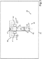
- Fig. 1 shows a motor vehicle 10, which may be, for example, a motor vehicle, especially a passenger car, act.
- the motor vehicle 10 may have an antenna arrangement 11, by means of which a radio link 12 between the motor vehicle 10 and a mobile radio network 13 and / or between the motor vehicle 10 and a WLAN router 14 can be provided or manufactured.
- a position signal 15 of a GNSS Global Navigation Satellite System
- GPS Global Positioning System
- a broadcast signal 16 is received from a satellite radio 17.
- a radio link with a mobile terminal 20 is provided or manufactured, which may be located in an interior 21 of the motor vehicle 10.
- the mobile radio network 13, the WLAN router 14, the GNSS and the satellite radio 17 each represent an object which is arranged in an environment 22 of the motor vehicle 10.
- the antenna arrangement may comprise a roof antenna module 23 which may be mounted on a roof 24 of the motor vehicle 10.
- the roof 24 may be formed or provided by means of an outer panel 25 of the motor vehicle 10.
- the roof antenna module 23 can be connected via a connecting line 26 to a vehicle component 27.
- the vehicle component 27 may be, for example, a gateway for at least one wired communication network 28.
- the at least one communication network 28 may comprise, for example, an Ethernet network and / or a CAN bus (CAN controller area network).
- the antenna arrangement 11 converts transmission signals 29 from the vehicle component 27 into the described radio signals.
- radio signals received by the antenna arrangement 11 are converted into electrical reception signals 30 for the vehicle component 27.
- the transmission signals 29 and the reception signals 30 can exchange the vehicle component 27 via the at least one communication network 28 with at least one further vehicle component 31, for example with an infotainment system (information entertainment system).
- the roof antenna module 23 may include a cap or a housing 32 in which a control circuit 33 may be arranged, through which the antenna assembly 11 can be operated.
- the antenna assembly 11 may include, for example, a first antenna 34 and a second antenna 35.
- the first antenna 34 is configured as a monopole structure. It may have a fin 36 on which the monopole may be arranged as a metal strip 37 so that the metal strip 37 projects perpendicularly from a plane of the roof 24.
- the fin 34 can be made of a plastic.
- the housing 32 may be made of a plastic.
- the antenna 35 may be, for example, a patch antenna for receiving the described satellite signals.
- the control circuit 33 may be configured as a printed circuit board. Via the control circuit 33, the antennas 34, 35 may be coupled to the connecting cable 26.
- the control circuit 33 can be designed to operate the antennas 34, 35 in a manner known per se.
- the roof antenna module 23 may include a floor 38, which may be formed of metal, for example.
- a contact area of the floor 38 on the roof 24 represents a support area A on an outer side A 'of the outer panel 25.
- a nozzle 39 may be arranged, which for mounting the roof antenna module 23 on the roof 24 in a through hole 40 in the Outer sheet 35 of the roof 34 can be plugged.
- the antenna arrangement 11 may comprise a further antenna which, although it can likewise be operated by the control circuit 33, does not have to be part of the roof antenna module itself.
- this further antenna may be a slot antenna 41, which may be formed as a slot 42 in the outer panel 25 of the roof 24 itself.
- the control circuit 33 may have a feed line 43, via which an electrical alternating voltage can be fed or applied or generated at edges 44 of the slot 42. This results in a feed point 45 of the slot antenna 41.
- the feed line 43 may be galvanically or capacitively or inductively coupled to the edges 44.
- the excitation of the slots 41 can then directly (galvanic, capacitive, inductive) respectively. But it can also be an indirect excitation (by means of aperture coupling, parasitic coupling, as a director, as a reflector).
- the slots can also act only as part of an antenna, so correlated or operated in combination with another antenna.
- the slot 42 represents a passage opening in the outer panel 25.
- the slot 42 has a longitudinal extent 46 along which a slot length 47 of the slot 42 can be measured.
- the slot has a rectangular shape, wherein the slot length 47 in relation to the slot width 48 transverse to the slot length 47 by at least a factor of 2, in particular by a factor of 3 is smaller.
- Fig. 3 also shows an alternative embodiment 49 of the slot 42, in which the slot 42 has a forked or branched end, wherein in Fig. 3 It is illustrated that in this case the slot length 47 can be measured as the slot length 47 ', for example along the center line of the slot 42.
- the slot length 47, 47 ' is in a range which corresponds to a half and / or a quarter wavelength of a respective frequency of an operating frequency interval, with which the control circuit 33, the antenna assembly 11 operates.
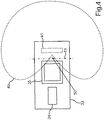
- Fig. 4 illustrates a directional characteristic 49, as it can be formed by means of the slot antenna 41 in the transmission and / or reception of radio waves.
- the directional characteristic 49 may have a zero point 50, which may be aligned in the direction of the antenna 34 and / or the antenna 35.
- a decoupling 51 between the slot antenna 41 and the antennas 34, 35 causes.
- the coupling 51 is in Fig. 4 symbolically represented by a hyphen.
- At least one electrically conductive additional element 41 ' is provided which, like the monopole 37, represents a raised structure on the outer panel 35. It may, for example, each be a metal rod or a bent sheet metal piece or a stamped and bent part. This allows the Directional characteristic 49 set or changed for at least one frequency from the operating frequency interval.
- antenna slots are thus (shown for clarity only one) inserted into the roof. Each slot is then used as an antenna (preferably only for one radio service or one radio connection of a type).
- the great advantage that results from this is that an antenna directivity characteristic 29 can be realized which has a pole or zero point 50 in the direction of the remaining antennas or emitters 34, 35, such as a telephone emitter.
- the antennas shown to be operated separately or independently of each other can be confined in a small space, i. the surface on the roof (25), decoupled and operated.
- the directional characteristic 49 may additionally or alternatively provide that the radio link 19 to the terminal 20 in the interior 21 is provided by means of the slot 42 as a slot antenna 41.
- a slot antenna can be provided.
- a slot structure may be provided that includes one or more slots. It may be provided in a metallic, electrically conductive outer panel of the motor vehicle 10 and excited via a suitable supply for radiating radio waves in the operating frequency interval. The structure may have branches, radii or developments.
- the slot structure be sealed towards the environment 22 by means of the roof antenna module 23.
- the slot antenna 41 is arranged in the support area A.
- the one slot structure can be introduced by means of stamping technology or laser technology or another construction technique in a headliner of a motor vehicle, ie in its outer panel 25.
- Such a construction offers the advantages that a good antenna position can be used, but no additional holder for an antenna must be constructed and antennas can be constructed which illuminate both the exterior of the environment 22 and the passenger compartment in the interior 21 (for example for Bluetooth and / or WLAN).
- the slot antenna described in the space of the roof antenna offers the advantage of free arrangement of other antennas on the described bottom plate 38. Furthermore, the influence on satellite antennas is low on such a slot structure in the outer panel.
Landscapes
- Engineering & Computer Science (AREA)
- Remote Sensing (AREA)
- Computer Networks & Wireless Communication (AREA)
- Signal Processing (AREA)
- Support Of Aerials (AREA)
- Details Of Aerials (AREA)
- Waveguide Aerials (AREA)
Description
Die Erfindung betrifft ein Kraftfahrzeug, das eine Antennenanordnung zum Austauschen von elektromagnetischen Funkwellen mit zumindest einem Objekt in einer Umgebung und eine Steuerschaltung zum Betreiben der Antennenanordnung in einem vorbestimmten Betriebsfrequenzintervall aufweist.The invention relates to a motor vehicle having an antenna arrangement for exchanging electromagnetic radio waves with at least one object in an environment and a control circuit for operating the antenna arrangement in a predetermined operating frequency interval.
Ein Kraftfahrzeug kann über Funkempfang und bidirektionale Funkverbindungen Informationen mit Objekten in der Umgebung austauschen. Durch die steigenden Anforderungen an die Menge und Qualität und Datenrate solcher kabelloser Dienste nimmt die Anzahl der in einem Kraftfahrzeug zu verbauenden Antennen stetig zu. Demgegenüber steht der Anspruch, die Antennen möglichst versteckt zu verbauen. Um aber einen möglichst richtungsunabhängigen und unblockierten Empfang rund um das Kraftfahrzeug zu haben, wie es zum Beispiel für Bluetooth, Telefonie und Internetanbindungen nötig ist, sowie auch einen Empfang von Satellitendiensten zu ermöglichen, ist der bevorzugte Verbauort für eine Antennenanordnung das Fahrzeugdach. Baut man allerdings mehrere, unabhängig voneinander betriebene Antennen nebeneinander in einem Dachantennenmodul ein, so beeinflussen sich die Antennen im Betrieb gegenseitig.A motor vehicle can exchange information with objects in the environment via radio reception and bidirectional radio links. Due to the increasing demands on the quantity and quality and data rate of such wireless services, the number of antennas to be installed in a motor vehicle is steadily increasing. In contrast, there is the demand to obstruct the antennas as hidden as possible. However, in order to have a direction-independent and unblocked reception around the motor vehicle, as is necessary, for example, for Bluetooth, telephony and Internet connections, as well as to enable reception of satellite services, the preferred installation site for an antenna arrangement is the vehicle roof. However, if one builds several, independently operated antennas side by side in a roof antenna module, the antennas affect each other in operation.
Ein Dachantennenmodul der beschriebenen Art ist zum Beispiel aus der
Aus der
Aus der
Weitere Antennensysteme für Fahrzeuge sind aus der
Der Erfindung liegt die Aufgabe zugrunde, in einem Kraftfahrzeug eine Antenne mit geringem zusätzlichen Bauraumbedarf bereitzustellen.The invention has for its object to provide an antenna with little additional space requirement in a motor vehicle.
Die Aufgabe wird durch die Gegenstände der unabhängigen Patentansprüche gelöst. Vorteilhafte Weiterbildungen der Erfindung sind durch die Merkmale der abhängigen Patentansprüche, die folgende Beschreibung sowie die Figuren offenbart.The object is solved by the subject matters of the independent claims. Advantageous developments of the invention are disclosed by the features of the dependent claims, the following description and the figures.
Durch die Erfindung ist ein Kraftfahrzeug bereitgestellt. Das Kraftfahrzeug weist in bekannter Weise ein Außenblech aus einem elektrisch leitfähigen Material auf, also ein Außenblech, das zum Beispiel aus Stahl oder Aluminium gebildet ist. Das Außenblech grenzt einen Innenraum des Kraftfahrzeugs zu einer Umgebung des Kraftfahrzeugs hin ab. Eine andere Bezeichnung für ein solches Außenblech ist auch Außenhaut. Das Außenblech ist insbesondere als Dach oder A-Säule oder B-Säule oder C-Säule oder Kofferraumklappe oder Tür des Kraftfahrzeugs ausgestaltet.The invention provides a motor vehicle. The motor vehicle has, in a known manner, an outer panel of an electrically conductive material, that is to say an outer panel, which is formed, for example, from steel or aluminum. The outer panel defines an interior of the motor vehicle from an environment of the motor vehicle. Another name for such an outer panel is also outer skin. The outer panel is designed in particular as a roof or A-pillar or B-pillar or C-pillar or trunk lid or door of the motor vehicle.
Eine Antennenanordnung des Kraftfahrzeugs ist dazu eingerichtet, elektromagnetische Funkwellen mit zumindest einem Objekt in der Umgebung auszutauschen. Das Austauschen von Funkwellen kann sowohl das Aussenden von Funkwellen hin zu dem zumindest einen Objekt und/oder das Empfangen von Funkwellen von dem zumindest einen Objekt umfassen. Die Antennenanordnung weist hierzu eine vorbestimmte Richtcharakteristik auf. Zum Betreiben der Antennenanordnung ist eine Steuerschaltung bereitgestellt. Die Steuerschaltung betreibt die Antennenanordnung in einem vorbestimmten Betriebsfrequenzintervall. Beispielsweise kann die Antennenanordnung in einem Betriebsfrequenzintervall von 700 MHz bis 3 GHz betrieben werden. Die Antennenanordnung kann eine einzelne Antenne oder mehrere Antennen aufwiest, die gekoppelt oder unabhängig voneinander durch die Steuerschaltung betrieben werden können. Durch die Steuerschaltung wird dazu ein elektrisches Signal in der Antennenanordnung erzeugt, damit diese eine elektromagnetische Welle oder Funkwelle aussendet. Zusätzlich oder alternativ dazu kann durch die Steuerschaltung ein elektrisches Signal, dass durch eine Funkwelle in der Antennenanordnung erzeugt wird, abgegriffen und in das Kraftfahrzeug weitergeleitet werden.An antenna arrangement of the motor vehicle is set up to exchange electromagnetic radio waves with at least one object in the environment. The replacement of radio waves may comprise both the transmission of radio waves towards the at least one object and / or the reception of radio waves from the at least one object. For this purpose, the antenna arrangement has a predetermined directional characteristic. For operating the antenna arrangement, a control circuit is provided. The control circuit operates the antenna arrangement in a predetermined operating frequency interval. For example, the antenna arrangement can be operated in an operating frequency interval of 700 MHz to 3 GHz. The antenna arrangement may comprise a single antenna or a plurality of antennas which may be coupled or independently operated by the control circuit. For this purpose, an electrical signal is generated in the antenna arrangement by the control circuit, so that it emits an electromagnetic wave or radio wave. Additionally or alternatively, by the control circuit, an electrical signal that is generated by a radio wave in the antenna arrangement, tapped and forwarded to the motor vehicle.
Um nun die Antennenanordnung besonders kompakt auszugestalten und/oder mit geringem zusätzlichen Bauraumbedarf, ist erfindungsgemäß vorgesehen, dass die Antennenanordnung zumindest eine Schlitzantenne umfasst. Eine Schlitzantenne ist bereitstellbar, indem in einem elektrisch leitfähigen Körper, z.B. einer Platte, ein Schlitz oder Spalt gebildet wird, also eine Durchgangsöffnung, die eine längliche Form aufweist, beispielsweise eine Rechteckform. Bei dem erfindungsgemäßen Kraftfahrzeug ist die zumindest eine Schlitzantenne in dem Außenblech als jeweiliger Schlitz bereitgestellt oder ausgebildet. Es ist also kein zusätzliches Bauteil vorgesehen, sondern das Außenblech selbst ist geschlitzt ausgestaltet. Die Schlitzlänge jedes Schlitzes entspricht bevorzugt einer halben Wellenlänge und/oder einer viertel Wellenlänge einer jeweiligen Frequenz des Betriebsfrequenzintervalls. Mit anderen Worten ist zumindest eine Schlitzantenne auf die Steuerschaltung beziehungsweise auf das Betriebsfrequenzintervall abgestimmt.In order to design the antenna arrangement to be particularly compact and / or with little additional space requirement, it is provided according to the invention that the antenna arrangement comprises at least one slot antenna. A slot antenna can be provided by placing in an electrically conductive body, e.g. a plate, a slot or gap is formed, that is, a through hole having an elongated shape, for example, a rectangular shape. In the motor vehicle according to the invention, the at least one slot antenna is provided or formed in the outer panel as a respective slot. So there is no additional component provided, but the outer panel itself is designed slotted. The slot length of each slot preferably corresponds to one half wavelength and / or one quarter wavelength of a respective frequency of the operating frequency interval. In other words, at least one slot antenna is tuned to the control circuit or to the operating frequency interval.
Es ist erfindungsgemäß also vorgesehen, in dem Außenblech eine Durchgangsöffnung bereitzustellen. Die Schlitzform eines Schlitzes einer Schlitzantenne kann hierbei gerade, geknickt oder gekrümmt sein. Der Schlitz kann mit anderen Worten gerade ausgestaltet sein, beispielsweise in Form eines Rechtecks, oder gekrümmt sein oder eine Abzweigung aufweisen oder eine Abwicklung oder einen Radius. Die Kanten des Außenblechs können im Bereich des Schlitzes in rechten Winkeln zueinander angeordnet sein oder in einem anderen Winkel oder auch über Rundungen verbunden sein. Wesentlich ist, dass die Schlitzlänge, also die Länge entlang einer Längserstreckungsrichtung des Schlitzes, in der beschriebenen Weise auf die Wellenlänge zumindest einer Frequenz des Betriebsfrequenzintervalls abgestimmt ist. Bei einer geknickten Schlitzform wird die Schlitzlänge entlang des Knickes, also nicht diagonal abgekürzt, gemessen. Eine absolute, maximale Abmessung des Schlitzes ist dabei insbesondere kürzer als 40 cm, insbesondere kürzer als 20 cm.It is therefore provided according to the invention to provide a passage opening in the outer panel. The slot shape of a slot of a slot antenna may be straight, kinked or curved. In other words, the slot may be straight, for example in the form of a rectangle, or curved or have a branch or a development or a radius. The edges of the outer panel may be arranged in the region of the slot at right angles to each other or be connected at a different angle or over curves. It is essential that the slot length, ie the length along a longitudinal extension direction of the slot, is tuned in the manner described to the wavelength of at least one frequency of the operating frequency interval. In a kinked slot shape, the slot length is measured along the kink, so not diagonal shortened. An absolute, maximum dimension of the slot is in particular shorter than 40 cm, in particular shorter than 20 cm.
Zum Bereitstellen eines Schlitzes in dem Außenblech kann der Schlitz beispielsweise gestanzt oder ausgeschnitten werden. Zum Ausschneiden kann zum Beispiel ein Laserschnittverfahren verwendet werden. Der Schlitz ist dann vollständig von dem elektrisch leitenden Material des Außenblechs umgeben oder durch dieses abgegrenzt oder begrenzt. Die Geometrie der jeweiligen Schlitzantenne ist insbesondere auf das Betriebsfrequenzintervall dahingehend abgestimmt, dass ein Wirkungsgrad der Schlitzantenne für zumindest eine Frequenz des Betriebsfrequenzbereichs größer als 30 Prozent, bevorzugt größer als 40 Prozent, ist. In dem Schlitz der jeweiligen Schlitzantenne ist bevorzugt Luft oder ein anderes Dielektrikum oder elektrisch isolierendes Material angeordnet.For example, to provide a slot in the outer panel, the slot may be punched or cut out. For cutting, for example, a laser cutting method can be used. The slot is then completely surrounded by the electrically conductive material of the outer panel or delimited or limited by this. The geometry of the respective slot antenna is tuned in particular to the operating frequency interval to the effect that the efficiency of the slot antenna for at least a frequency of the operating frequency range greater than 30 percent, preferably greater than 40 percent, is. Air or another dielectric or electrically insulating material is preferably arranged in the slot of the respective slot antenna.
Das erfindungsgemäße Kraftfahrzeug weist den Vorteil auf, dass zumindest eine Antenne der Antennenanordnung zum Beispiel im Bereich eines Dachantennenmoduls bereitgestellt werden kann, ohne dass hierzu innerhalb des Dachantennenmoduls Bauraum für die Antenne bereitgestellt werden muss. Stattdessen kann das Außenblech des Fahrzeugdaches die Schlitzantenne oder mehrere Schlitzantennen aufweisen, die dann durch die Steuerschaltung betrieben werden können, die zum Beispiel in dem Dachantennenmodul angeordnet sein kann.The motor vehicle according to the invention has the advantage that at least one antenna of the antenna arrangement can be provided, for example, in the region of a roof antenna module, without having to provide installation space for the antenna within the roof antenna module. Instead, the outer panel of the vehicle roof may include the slot antenna or a plurality of slot antennas, which may then be operated by the control circuitry, which may be disposed in the roof antenna module, for example.
Zu der Erfindung gehören auch vorteilhafte Weiterbildungen, durch deren Merkmale sich zusätzliche Vorteile ergeben.The invention also includes advantageous developments, the characteristics of which provide additional advantages.
Durch die zumindest eine Schlitzantenne kann eine Richtcharakteristik der Antennenanordnung ausgebildet sein, bei welcher für zumindest eine Frequenz aus dem Betriebsfrequenzintervall eine Nullstelle in eine Richtung einer von der jeweiligen Schlitzantenne unabhängig durch die Steuerschaltung betriebenen weiteren Antenne der Antennenanordnung ausgerichtet ist. Dies dient zur Entkopplung der zumindest einen Schlitzantenne von der weiteren Antenne. Beispielsweise kann als die weitere Antenne ein Monopol oder eine Stabantenne bereitgestellt sein. Durch die beschriebene Richtcharakteristik wird diese weitere Antenne nicht oder nur geringfügig von Funkwellen der zumindest einen Schlitzantenne beaufschlagt oder beeinträchtig, so dass beim Senden mittels der zumindest einen Schlitzantenne keine oder nur geringfügig Sendeleistung in die weitere Antenne eingetragen oder eingeprägt wird. Hierdurch kann ein Abstand zwischen der weiteren Antenne und der zumindest einen Schlitzantenne entsprechend gering gewählt werden, insbesondere kleiner als 20 Zentimeter.By means of the at least one slot antenna, a directional characteristic of the antenna arrangement can be formed in which, for at least one frequency from the operating frequency interval, a zero point is aligned in one direction of a further antenna of the antenna arrangement operated independently of the respective slot antenna by the control circuit. This serves to decouple the at least one slot antenna from the further antenna. For example, a monopole or a rod antenna may be provided as the further antenna. As a result of the described directional characteristic, this further antenna is not or only slightly acted upon or impaired by radio waves of the at least one slot antenna, so that when transmitting by means of the at least one slot antenna no or only slightly transmitting power is entered or impressed into the further antenna. In this way, a distance between the further antenna and the at least one slot antenna can be selected correspondingly small, in particular smaller than 20 centimeters.
Durch die zumindest eine Schlitzantenne kann auch eine Richtcharakteristik ausgebildet sein, bei welcher für zumindest eine Frequenz aus dem Betriebsfrequenzintervall ein Sendebereich und/oder ein Empfangsbereich der Antennenanordnung durch den jeweiligen Schlitz der Schlitzantenne hindurch in den Innenraum des Kraftfahrzeugs und dabei zugleich auch in die Umgebung des Kraftfahrzeugs ausgerichtet ist. Hierdurch kann mittels der zumindest einen Schlitzantenne eine Doppelversorgung bereitgestellt werden. So kann diese Richtcharakteristik zum Beispiel dazu genutzt werden einen Datenaustausch zwischen einem WLAN-Router des Kraftfahrzeugs einerseits und sowohl einem im Innenraum des Kraftfahrzeugs befindlichen mobilen Endgerät als auch einem in der Umgebung des Kraftfahrzeugs befindlichen Gerät (beispielsweise einer fest oder stationär installierten Kamera für eine Einparkhilfe) zu ermöglichen. Das genannte mobile Endgerät kann z.B. ein Smartphone und/oder ein Tablet-PC und/oder eine Smartwatch sein.By means of the at least one slot antenna, a directional characteristic can also be formed in which for at least one frequency from the operating frequency interval a transmission range and / or a reception range of the antenna arrangement pass through the slot of the slot antenna into the interior of the motor vehicle and at the same time into the environment of the antenna Motor vehicle is aligned. In this way, by means of at least a slot antenna a dual supply can be provided. For example, this directional characteristic can be used to exchange data between a WLAN router of the motor vehicle on the one hand and a mobile terminal located in the interior of the motor vehicle and one located in the vicinity of the motor vehicle (for example a fixed or stationary camera for a parking aid ). Said mobile terminal may be, for example, a smartphone and / or a tablet PC and / or a smartwatch.
Bevorzugt ist vorgesehen, dass die Antennenanordnung ein Gehäuse aufweist, das an einer Außenseite des Außenblechs angeordnet ist. Der zumindest eine Schlitz, durch welchen jeweils eine Schlitzantenne gebildet ist, ist hierbei in einem von dem Gehäuse zur Umgebung hin abgedeckten Auflagebereich des Gehäuses angeordnet. Ist das Gehäuse also zum Beispiel auf einem Dach des Kraftfahrzeugs angeordnet, so befindet sich der zumindest eine Schlitz unterhalb des Gehäuses. Hierdurch wird mittels des Gehäuses der zumindest eine Schlitz zur Umgebung hin abgedichtet.It is preferably provided that the antenna arrangement has a housing which is arranged on an outer side of the outer panel. The at least one slot, through each of which a slot antenna is formed, is in this case arranged in a bearing area of the housing covered by the housing toward the surroundings. If the housing is thus arranged, for example, on a roof of the motor vehicle, the at least one slot is located below the housing. As a result, by means of the housing, the at least one slot is sealed to the environment.
Die Erfindung ist insbesondere im Zusammenhang mit der Verwendung eines Antennenmoduls vorteilhaft, also eines einstückigen Bauteils. Das besagte Gehäuse kann zum Beispiel Bestandteil des besagten Antennenmoduls sein, insbesondere eines Dachantennenmoduls. Hierbei kann zumindest eine Anschlussleitung der Steuerschaltung über eine Durchgangsöffnung des Außenblechs von dem Innenraum des Kraftfahrzeugs in das Gehäuse geführt sein. Die zumindest eine Anschlussleitung kann beispielsweise ein Koaxialkabel umfassen, um ein Sendesignal aus dem Innenraum zu der Steuerschaltung hin zu übertragen und/oder ein über die Antennenanordnung empfangenes Signal als elektrisches Empfangssignal in den Innenraum zu übertragen. Hierbei kann nun vorgesehen sein, dass diese Durchgangsöffnung selbst als eine Schlitzantenne ausgestaltet ist. Mit einer Worten ist die Steuerschaltung dazu eingerichtet, die Durchgangsöffnung als Schlitzantenne zu betreiben. Hierzu kann in die Durchgangsöffnung zum Beispiel auch zusätzlich ein elektrisch leitfähiges Material eingefügt sein, um hierdurch zumindest eine Kante des Schlitzes der Schlitzantenne zu bilden. Zumindest eine weitere Kante des Schlitzes kann durch das Außenblech selbst gebildet sein. Es kann aber auch vorgesehen sein, dass kein zusätzliches elektrisch leitfähiges Material zum Bilden der Schlitzantenne in der Durchgangsöffnung angeordnet ist.The invention is particularly advantageous in connection with the use of an antenna module, ie a one-piece component. The said housing may for example be part of the said antenna module, in particular a roof antenna module. In this case, at least one connecting line of the control circuit can be guided via a passage opening of the outer panel from the interior of the motor vehicle into the housing. The at least one connecting line may comprise, for example, a coaxial cable in order to transmit a transmission signal from the interior to the control circuit and / or to transmit a signal received via the antenna arrangement as an electrical reception signal into the interior. It can now be provided that this passage opening itself is designed as a slot antenna. In a word, the control circuit is configured to operate the through hole as a slot antenna. For this purpose, for example, in addition, an electrically conductive material may be inserted into the passage opening in order to thereby form at least one edge of the slot of the slot antenna. At least one further edge of the slot can be formed by the outer panel itself. However, it can also be provided that no additional electrically conductive material for forming the slot antenna is arranged in the passage opening.
Bei der Erfindung ist aber insbesondere vorgesehen, dass zumindest ein von der Durchgangsöffnung verschiedener Schlitz zusätzlich oder alternativ als Schlitzantenne durch die Steuerschaltung betreibbar ist. Mit anderen Worten gibt es zusätzlich zu der Durchgangsöffnung zumindest einen Schlitz in dem Außenblech, welcher jeweils eine Schlitzantenne der Antennenanordnung bildet oder darstellt.In the invention, however, provision is made in particular for at least one slot which is different from the passage opening to be operated additionally or alternatively as a slot antenna by the control circuit. In other words, in addition to the passage opening, there is at least one slot in the outer panel, which each forms or represents a slot antenna of the antenna arrangement.
Jede Schlitzantenne kann auf unterschiedliche Weise durch die Steuerschaltung betrieben oder genutzt werden. So sieht eine Ausführungsform der Erfindung vor, dass die Steuerschaltung dazu eingerichtet ist, in einem durch die Steuerschaltung bewirkten Betrieb der Antennenanordnung die zumindest eine Schlitzantenne über eine Speiseleitung direkt als Strahler bei einer Frequenz, die in dem Betriebsfrequenzintervall liegt, anzuregen. Hierzu ist die Steuerschaltung dazu eingerichtet, über eine jeweilige Speiseleitung ein Wechselspannungssignal galvanisch oder kapazitiv oder induktiv in einen den jeweiligen Schlitz der zumindest einen Schlitzantenne begrenzenden Rand einzuspeisen (Senden) und/oder das Wechselspannungssignal von dort abzugreifen (Empfangen). Zum Bereitstellen der zumindest einen Speiseleitung kann die Steuerschaltung eine Leiterplatte (PCB - printed circuit board) aufweisen. Eine Speiseleitung kann durch zumindest eine Leiterbahn der Leiterplatte gebildet sein. Im Zusammenhang mit dem Dachantennenmodul kann diese Leiterplatte in dem Dachantennenmodul bereitgestellt oder angeordnet sein.Each slot antenna can be operated or utilized in different ways by the control circuit. Thus, an embodiment of the invention provides that the control circuit is set up to excite, in an operation of the antenna arrangement caused by the control circuit, the at least one slot antenna via a feed line directly as a radiator at a frequency which is within the operating frequency interval. For this purpose, the control circuit is adapted to supply via a respective feed line an AC voltage signal galvanically or capacitively or inductively in a respective slot of the at least one slot antenna limiting edge (send) and / or tap the AC signal from there (receiving). To provide the at least one supply line, the control circuit may have a printed circuit board (PCB). A feed line may be formed by at least one conductor track of the printed circuit board. In connection with the roof antenna module, this printed circuit board can be provided or arranged in the roof antenna module.
Die zumindest eine Schlitzantenne stellt für die jeweilige Speiseleitung einen Abschlusswiderstand dar. Insbesondere ist vorgesehen, dass die Anpassung der Antenne gleich dem Wert der Leitungsimpedanz der Speiseleitung selbst ist. Hierzu kann ein Wert eines Abschlusswiderstands des Schlitzes selbst an die Leitungsimpedanz angepasst sein. Alternativ dazu kann eine Anpassschaltung bereitgestellt sein, über welche der Schlitz an die Leitung angepasst ist. Hierdurch kann die Impdedanz über ein Anpassnetzwerk der Anpassschaltung transformiert werden. Bevorzugt liegt der Impedanzwert in einem Bereich von 30 Ohm bis 100 Ohm.The at least one slot antenna represents a terminating resistor for the respective feed line. In particular, it is provided that the matching of the antenna is equal to the value of the line impedance of the feed line itself. For this purpose, a value of a terminating resistor of the slot itself can be adapted to the line impedance. Alternatively, a matching circuit may be provided over which the slot is adapted to the line. As a result, the impedance dance can be transformed via a matching network of the matching circuit. Preferably, the impedance value is in a range of 30 ohms to 100 ohms.
Zusätzlich oder alternativ kann die Steuerschaltung auch dazu eingerichtet sein, zumindest eine Schlitzantenne indirekt zu betreiben. Die Steuerschaltung ist dabei dazu eingerichtet, bei zumindest einer Frequenz, die in dem Betriebsfrequenzintervall liegt, die zumindest eine Schlitzantenne indirekt als einen Direktor oder Reflektor oder als eine Apertur zu betreiben. Mit anderen Worten ist zumindest eine weitere Antenne bereitgestellt, beispielsweise eine Stabantenne oder ein Monopol, dessen elektromagnetisches Feld mit der zumindest einen Schlitzantenne wechselwirkt, um hierdurch die beschriebene Richtcharakteristik zu erhalten. Dabei stellt die zumindest eine Schlitzantenne einen Direktor/Reflektor/eine Apertur dar.Additionally or alternatively, the control circuit may also be configured to operate at least one slot antenna indirectly. In this case, the control circuit is set up to operate the at least one slot antenna indirectly as a director or reflector or as an aperture at at least one frequency which lies in the operating frequency interval. With others In other words, at least one further antenna is provided, for example a rod antenna or a monopole, the electromagnetic field of which interacts with the at least one slot antenna in order to obtain the directional characteristic described. The at least one slot antenna represents a director / reflector / aperture.
Das erfindungsgemäße Kraftfahrzeug ist bevorzugt als Kraftwagen, insbesondere als Personenkraftwagen oder Lastkraftwagen, ausgestaltet.The motor vehicle according to the invention is preferably designed as a motor vehicle, in particular as a passenger car or truck.
Im Folgenden ist ein Ausführungsbeispiel der Erfindung beschrieben. Hierzu zeigt:
- Fig. 1
- eine schematische Darstellung einer Ausführungsform des erfindungsgemäßen Kraftfahrzeugs;
- Fig. 2
- eine schematische Darstellung einer perspektivischen Ansicht eines Dachantennenmoduls, das auf einem Dach an einem Außenblechs des Kraftfahrzeugs befestigt wird;
- Fig. 3
- eine schematische Darstellung einer Schlitzantenne, die in dem Außenblech des Daches des Kraftfahrzeugs unterhalb des Dachantennenmoduls bereitgestellt ist; und
- Fig. 4
- eine schematische Darstellung einer Draufsicht auf das Dachantennenmodul von
Fig. 2 zusammen mit einer Richtcharakteristik, die mittels der Schlitzantenne vonFig. 3 bereitgestellt sein kann.
- Fig. 1
- a schematic representation of an embodiment of the motor vehicle according to the invention;
- Fig. 2
- a schematic representation of a perspective view of a roof antenna module which is mounted on a roof to an outer panel of the motor vehicle;
- Fig. 3
- a schematic representation of a slot antenna, which is provided in the outer panel of the roof of the motor vehicle below the roof antenna module; and
- Fig. 4
- a schematic representation of a plan view of the roof antenna module of
Fig. 2 together with a directional characteristic, by means of the slot antenna ofFig. 3 can be provided.
Bei dem im Folgenden erläuterten Ausführungsbeispiel handelt es sich um eine bevorzugte Ausführungsform der Erfindung. Bei dem Ausführungsbeispiel stellen die beschriebenen Komponenten der Ausführungsform jeweils einzelne, unabhängig voneinander zu betrachtende Merkmale der Erfindung dar, welche die Erfindung jeweils auch unabhängig voneinander weiterbilden und damit auch einzeln oder in einer anderen als der gezeigten Kombination als Bestandteil der Erfindung anzusehen sind. Des Weiteren ist die beschriebene Ausführungsform auch durch weitere der bereits beschriebenen Merkmale der Erfindung ergänzbar.The exemplary embodiment explained below is a preferred embodiment of the invention. In the exemplary embodiment, the described components of the embodiment each represent individual features of the invention that are to be considered independently of one another, which also each independently further develop the invention and thus also individually or in a different combination than the one shown as part of the invention. Furthermore, the described embodiment can also be supplemented by further features of the invention already described.
In den Figuren sind funktionsgleiche Elemente jeweils mit denselben Bezugszeichen versehen.In the figures, functionally identical elements are each provided with the same reference numerals.
Zum Aussenden der beschriebenen Funksignale und zum Empfangen dieser Funksignale kann die Antennenanordnung ein Dachantennenmodul 23 aufweisen, das auf einem Dach 24 des Kraftfahrzeugs 10 montiert sein kann. Das Dach 24 kann mittels eines Außenblechs 25 des Kraftfahrzeugs 10 gebildet oder bereitgestellt sein. Das Dachantennenmodul 23 kann über eine Anschlussleitung 26 mit einer Fahrzeugkomponente 27 verschaltet sein. Die Fahrzeugkomponente 27 kann zum Beispiel ein Gateway für zumindest ein kabelgebundenes Kommunikationsnetzwerk 28 sein. Das zumindest eine Kommunikationsnetzwerk 28 kann zum Beispiel ein Ethernet-Netzwerk und/oder einen CAN-Bus (CAN-Controller Area Network) umfassen. Die Antennenanordnung 11 wandelt Sendesignale 29 aus der Fahrzeugkomponente 27 in die beschriebenen Funksignale um. Des Weiteren werden durch die Antennenanordnung 11 empfangene Funksignale in elektrische Empfangssignale 30 für die Fahrzeugkomponente 27 umgewandelt. Die Sendesignale 29 und die Empfangssignale 30 kann die Fahrzeugkomponente 27 über das zumindest eine Kommunikationsnetzwerk 28 mit zumindest einer weiteren Fahrzeugkomponente 31 austauschen, zum Beispiel mit einem Infotainmentsystem (Information-Unterhaltungssystem).For emitting the described radio signals and for receiving these radio signals, the antenna arrangement may comprise a
Die Steuerschaltung 33 kann als eine Leiterplatte ausgestaltet sein. Über die Steuerschaltung 33 können die Antennen 34, 35 mit dem Anschlusskabel 26 gekoppelt sein. Die Steuerschaltung 33 kann zum Betreiben der Antennen 34, 35 in an sich bekannter Weise ausgestaltet sein.The
Das Dachantennenmodul 23 kann einen Boden 38 aufweisen, der zum Beispiel aus Metall gebildet sein kann. Ein Berührbereich des Bodens 38 auf dem Dach 24 stellt einen Auflagebereich A an einer Außenseite A' des Außenblechs 25 dar. An dem Boden 38 kann ein Stutzen 39 angeordnet sein, welcher zum Befestigen des Dachantennenmoduls 23 auf dem Dach 24 in eine Durchgangsöffnung 40 in dem Außenblechs 35 des Daches 34 gesteckt sein kann.The
Die Antennenanordnung 11 kann eine weitere Antenne umfassen, die zwar ebenfalls durch die Steuerschaltung 33 betrieben werden kann, die aber nicht Bestandteil des Dachantennenmoduls selbst sein muss. Bei dieser weiteren Antenne kann es sich um eine Schlitzantenne 41 handeln, die als ein Schlitz 42 in dem Außenblechs 25 des Daches 24 selbst ausgebildet sein kann. Die Steuerschaltung 33 kann eine Speiseleitung 43 aufweisen, über welche ein elektrische Wechselspannung an Rändern 44 des Schlitzes 42 eingespeist oder angelegt oder erzeugt werden kann. Hierdurch ergibt sich ein Einspeisepunkt 45 der Schlitzantenne 41. Die Speiseleitung 43 kann mit den Rändern 44 galvanisch oder kapazitiv oder induktiv gekoppelt sein. Die Anregung der Schlitze 41 kann dann direkt (galvanisch, kapazitiv, induktiv) erfolgen. Es kann aber auch eine indirekt Anregung (mittels Apertur-Kopplung, parasitärer Kopplung, als Direktor, als Reflektor) erfolgen.The
Die Schlitze können dabei ebenfalls auch nur als ein Teil einer Antenne wirken, also korreliert oder kombiniert mit einer weiteren Antenne betrieben werden.The slots can also act only as part of an antenna, so correlated or operated in combination with another antenna.
Die Schlitzlänge 47, 47' liegt in einem Bereich, welcher einer halben und/oder einer viertel Wellenlänge einer jeweiligen Frequenz eines Betriebsfrequenzintervalls entspricht, mit welchem die Steuerschaltung 33 die Antennenanordnung 11 betreibt.The
Zusätzlich zu der Schlitzantenne 41 kann vorgesehen sein, dass zumindest ein elektrisch leitfähiges Zusatzelement 41' bereitgestellt ist, welches wie z.B. der Monopol 37 eine erhabene Struktur auf dem Außenblech 35 darstellt. Es kann sich beispielsweise jeweils um einen Metallstab oder um ein gebogenes Blechstück oder ein Stanzbiegeteil handeln. Hierdurch kann die Richtcharakteristik 49 für zumindest eine Frequenz aus dem Betriebsfrequenzintervall eingestellt oder verändert werden.In addition to the
Bei dem Kraftfahrzeug 10 sind somit Antennenschlitze (dargestellt ist der Übersichtlichkeit halber nur einer) in das Dach eingefügt. Jeder Schlitz wird dann als Antenne (bevorzugt lediglich für nur einen Funkdienst oder eine Funkverbindung eines Typs) genutzt. Der große Vorteil, der sich daraus ergibt, ist, dass sich so eine Antennenrichtcharakteristik 29 realisieren lässt, die in Richtung der übrigen Antennen oder Strahler 34, 35, wie zum Beispiel einen Telefonstrahler, eine Polstelle oder Nullstelle 50 aufweist.In the
Somit können die gezeigten Antennen, die separat oder unabhängig voneinander betrieben werden sollen, auf engem Raum, d.h. der Fläche auf dem Dach (25), entkoppelt und betrieben werden.Thus, the antennas shown to be operated separately or independently of each other can be confined in a small space, i. the surface on the roof (25), decoupled and operated.
Die Richtcharakteristik 49 kann zusätzlich oder alternativ vorsehen, dass auch die Funkverbindung 19 zu dem Endgerät 20 im Innenraum 21 mittels des Schlitzes 42 als Schlitzantenne 41 bereitgestellt wird.The directional characteristic 49 may additionally or alternatively provide that the
Somit kann durch Vorsehen einer Durchgangsöffnung oder eines Schlitzes 42 im Außenblechs 25 eines Daches 24 des Kraftfahrzeugs 10 eine Schlitzantenne bereitgestellt werden. Anstelle der gezeigten einfachen rechteckigen Schlitzform kann eine Schlitzstruktur bereitgestellt werden, die einen oder mehrere Schlitze umfasst. Sie kann in einem metallischen, elektrisch leitfähigen Außenblech des Kraftfahrzeugs 10 bereitgestellt werden und über eine geeignete Speisung zum Abstrahlen von Funkwellen in dem Betriebsfrequenzintervall angeregt werden. Die Struktur kann dabei Abzweigungen, Radien oder Abwicklungen aufweisen.Thus, by providing a through hole or
Vorgesehen ist hierbei bevorzugt auch, dass mittels des Dachantennenmoduls 23 die Schlitzstruktur zur Umgebung 22 hin auch abgedichtet wird. Hierzu ist die Schlitzantenne 41 in dem Auflagebereich A angeordnet.It is also preferred that the slot structure be sealed towards the
Die eine Schlitzstruktur kann mittels Stanztechnik oder Lasertechnik oder einer anderen Aufbautechnik in einem Dachhimmel eines Kraftfahrzeugs, also in dessen Außenblechs 25, eingebracht werden.The one slot structure can be introduced by means of stamping technology or laser technology or another construction technique in a headliner of a motor vehicle, ie in its
Die Doppelnutzung als Befestigung der Dachantenne am Dachhimmel durch das Außenblechs 25 ist dabei denkbar, wie auch die Übertragbarkeit dieses Ansatzes auf andere Bauräume, beispielsweise eine A-Säule oder einen Kotflügel oder eine Fahrzeugtür.The double use as attachment of the roof antenna on the headliner by the
Eine solche Konstruktion bietet die Vorteile, dass eine gute Antennenposition genutzt werden kann, hierbei aber kein zusätzlicher Halter für eine Antenne konstruiert werden muss und Antennen aufgebaut werden können, die sowohl den Außenraum der Umgebung 22 als auch den Fahrgastraum im Innenraum 21 ausleuchten (zum Beispiel für Bluetooth und/oder WLAN). Die beschriebene Schlitzantenne im Bauraum der Dachantenne bietet den Vorteil der freien Anordnung weiterer Antennen auf der beschriebenen Bodenplatte 38. Ferner ist über eine solche Schlitzstruktur im Außenblechs der Einfluss auf Satellitenantennen gering.Such a construction offers the advantages that a good antenna position can be used, but no additional holder for an antenna must be constructed and antennas can be constructed which illuminate both the exterior of the
Insgesamt zeigt das Beispiel, wie durch die Erfindung eine oder mehrere Schlitzantennenstrukturen in einem Kraftfahrzeug bereitgestellt und genutzt werden können.Overall, the example shows how one or more slot antenna structures in a motor vehicle can be provided and used by the invention.
Claims (9)
- Motor vehicle (10) having:- an outer plate (25) formed from an electrically conductive material, which delimits an interior (21) of the motor vehicle (10) towards an environment (22),- an antenna arrangement (11) for exchanging electromagnetic radio waves (12, 15, 16) with at least one object (13, 14, 17, GNSS) in the environment (22), wherein the antenna arrangement (11) has a predetermined directional characteristic (49), and- a control circuit (33) for operating the antenna arrangement (11) in a predetermined operating frequency interval,- wherein the antenna arrangement (11) comprises at least one slot antenna (41), which is provided in the outer plate (25) as a respective slot (42),characterised in that
a directional characteristic (49) is formed by the at least one slot antenna (41), in which for at least one frequency from the operating frequency interval for the decoupling (51) a zero point (50) is aligned in a direction of a further antenna (34, 35) of the antenna arrangement operated by the control circuit (33) independently of the respective slot antenna (41). - Motor vehicle (10) according to any one of the preceding claims, wherein a directional characteristic (49) is formed by the at least one slot antenna (41), in which for the at least one frequency from the operating frequency interval for the double supply (18) a transmission range and/or a reception range of the antenna arrangement (11) is aligned through the respective slot (42) of the slot antenna (41) both into the interior (21) as well as into the environment (22).
- Motor vehicle (10) according to any one of the preceding claims, wherein the control circuit (33) is designed as an antenna module (23), in particular as a roof antenna module, which is mounted outside of the outside plate (25).
- Motor vehicle (10) according to any one of the preceding claims, wherein the antenna arrangement (11) has a housing (32) arranged on an outer side of the outside plate (25) and the at least one slot (42) is arranged in a bearing area of the housing (32) covered from the housing (22) towards the environment (22).
- Motor vehicle (10) according to claim 4, wherein at least one connecting line (26) of the control circuit (33) is guided via a through-opening (40) provided in the outer plate (25) from the interior (21) to the housing (32) and the control circuit (33) is configured to operate the through-opening (40) as a slot antenna.
- Motor vehicle (10) according to any one of the preceding claims, wherein the control circuit (33) is configured in an operation of the antenna arrangement (11) effected by the control circuit (33) at a frequency in the operating frequency interval to excite the at least one slot antenna (41) via a supply line (43) directly as a radiator and for this purpose via a respective supply line (43) to supply an alternating voltage signal galvanically or capacitively or inductively into an edge (44) limiting the respective slot (42) of the at least one slot antenna (42) and/or to tap it from there.
- Motor vehicle (10) according to claim 6, wherein the at least one slot antenna (41) has an adjustment, which is equal to the value of the line impedance of the supply line itself.
- Motor vehicle (10) according to any one of the preceding claims, wherein the control circuit (33) is configured to operate the at least one slot antenna (41) indirectly as a director or reflector or an aperture in an operation of the antenna arrangement (11) effected by the control circuit (33) at at least a frequency in the operating frequency interval.
- Motor vehicle (10) according to any one of the preceding claims, wherein the respective slot (42) of each slot antenna (41) is stamped or cut into the outer plate (25).
Applications Claiming Priority (2)
| Application Number | Priority Date | Filing Date | Title |
|---|---|---|---|
| DE102016006975.9A DE102016006975B3 (en) | 2016-06-07 | 2016-06-07 | Motor vehicle with antenna arrangement |
| PCT/EP2017/061432 WO2017211536A1 (en) | 2016-06-07 | 2017-05-12 | Motor vehicle having an antenna arrangement |
Publications (2)
| Publication Number | Publication Date |
|---|---|
| EP3363077A1 EP3363077A1 (en) | 2018-08-22 |
| EP3363077B1 true EP3363077B1 (en) | 2019-02-13 |
Family
ID=58701645
Family Applications (1)
| Application Number | Title | Priority Date | Filing Date |
|---|---|---|---|
| EP17723098.4A Active EP3363077B1 (en) | 2016-06-07 | 2017-05-12 | Motor vehicle having an antenna arrangement |
Country Status (5)
| Country | Link |
|---|---|
| US (1) | US10270178B2 (en) |
| EP (1) | EP3363077B1 (en) |
| CN (1) | CN108475851B (en) |
| DE (1) | DE102016006975B3 (en) |
| WO (1) | WO2017211536A1 (en) |
Families Citing this family (6)
| Publication number | Priority date | Publication date | Assignee | Title |
|---|---|---|---|---|
| DE102016006975B3 (en) | 2016-06-07 | 2017-09-07 | Audi Ag | Motor vehicle with antenna arrangement |
| DE102017213374B3 (en) * | 2017-08-02 | 2018-10-11 | Audi Ag | Antenna arrangement for a vehicle |
| DE102018202098B3 (en) | 2018-02-12 | 2018-12-27 | Audi Ag | Vehicle roof antenna |
| CN111509403B (en) * | 2019-01-31 | 2022-02-18 | Oppo广东移动通信有限公司 | Array antenna and electronic device |
| CN110086494A (en) * | 2019-04-24 | 2019-08-02 | 大陆汽车电子(长春)有限公司 | Automobile-used wireless communication device, vehicle wireless communication method |
| DE102019213208B3 (en) * | 2019-09-02 | 2020-09-24 | Audi Ag | Roof antenna with embedded mmWave antenna |
Family Cites Families (23)
| Publication number | Priority date | Publication date | Assignee | Title |
|---|---|---|---|---|
| US4707700A (en) * | 1986-07-25 | 1987-11-17 | General Motors Corporation | Vehicle roof mounted slot antenna with lossy conductive material for low VSWR |
| US4866453A (en) * | 1988-08-15 | 1989-09-12 | General Motors Corporation | Vehicle slot antenna with parasitic slot |
| US5177494A (en) * | 1989-02-16 | 1993-01-05 | Robert Bosch Gmbh | Vehicular slot antenna system |
| DE8913811U1 (en) * | 1989-11-10 | 1990-01-11 | Robert Bosch Gmbh, 7000 Stuttgart, De | |
| US5168280A (en) * | 1991-08-16 | 1992-12-01 | Blaese Herbert R | Antenna with push-in cable connector |
| JPH06152489A (en) * | 1992-11-13 | 1994-05-31 | Ai Takagi | Antenna system for mobile object |
| US5402134A (en) * | 1993-03-01 | 1995-03-28 | R. A. Miller Industries, Inc. | Flat plate antenna module |
| US5451966A (en) * | 1994-09-23 | 1995-09-19 | The Antenna Company | Ultra-high frequency, slot coupled, low-cost antenna system |
| DE59501555D1 (en) * | 1995-04-20 | 1998-04-09 | Fuba Automotive Gmbh | Flat antenna arrangement |
| GB9910246D0 (en) | 1999-05-05 | 1999-06-30 | Asg Technology Limited | Concealed radio atenna system |
| DE19941476A1 (en) | 1999-09-01 | 2001-03-29 | Bosch Gmbh Robert | Antenna device for vehicles, is mounted on electrically insulated plate which is used as signal coupler of two circuits of antenna switch connected to base of antenna |
| DE10225569A1 (en) * | 2002-06-10 | 2003-12-18 | Kostal Leopold Gmbh & Co Kg | Keyless access control device for automobile with transfer of HF signals between onboard transceiver and mobile transponder |
| EP1487052B1 (en) * | 2003-01-25 | 2010-05-12 | Delphi Delco Electronics Europe GmbH | Antenna system in the aperture of an electrical conducting car body |
| DE10350034A1 (en) | 2003-10-27 | 2005-05-25 | Robert Bosch Gmbh | Antenna arrangement in particular for radar applications in motor vehicles |
| DE102005044610A1 (en) * | 2004-09-28 | 2006-03-30 | Hirschmann Car Communication Gmbh | Antenna and method for mounting an antenna to a vehicle by means of clamping force, preferably generated by a rotating bayonet |
| US20080117111A1 (en) * | 2006-11-22 | 2008-05-22 | Nippon Antena Kabushiki Kaisha | Antenna Apparatus |
| US8299971B2 (en) | 2009-03-25 | 2012-10-30 | GM Global Technology Operations LLC | Control module chassis-integrated slot antenna |
| DE102011076246B4 (en) * | 2011-05-20 | 2016-05-19 | Antonics-Icp Gmbh | Multi-band arrangement for radio signals and method for producing an associated exciter structure |
| US9083414B2 (en) * | 2012-08-09 | 2015-07-14 | GM Global Technology Operations LLC | LTE MIMO-capable multi-functional vehicle antenna |
| EP2806497B1 (en) * | 2013-05-23 | 2015-12-30 | Nxp B.V. | Vehicle antenna |
| EP3017502B1 (en) * | 2013-07-01 | 2019-08-21 | Intel Corporation | Airborne antenna system with controllable null pattern |
| US9905914B2 (en) * | 2015-01-07 | 2018-02-27 | GM Global Technology Operations LLC | Slot antenna built into a vehicle body panel |
| DE102016006975B3 (en) | 2016-06-07 | 2017-09-07 | Audi Ag | Motor vehicle with antenna arrangement |
-
2016
- 2016-06-07 DE DE102016006975.9A patent/DE102016006975B3/en active Active
-
2017
- 2017-05-12 US US16/066,837 patent/US10270178B2/en active Active
- 2017-05-12 EP EP17723098.4A patent/EP3363077B1/en active Active
- 2017-05-12 CN CN201780007071.6A patent/CN108475851B/en active Active
- 2017-05-12 WO PCT/EP2017/061432 patent/WO2017211536A1/en active Application Filing
Non-Patent Citations (1)
| Title |
|---|
| None * |
Also Published As
| Publication number | Publication date |
|---|---|
| CN108475851A (en) | 2018-08-31 |
| CN108475851B (en) | 2020-06-23 |
| US20190020115A1 (en) | 2019-01-17 |
| DE102016006975B3 (en) | 2017-09-07 |
| WO2017211536A1 (en) | 2017-12-14 |
| EP3363077A1 (en) | 2018-08-22 |
| US10270178B2 (en) | 2019-04-23 |
Similar Documents
| Publication | Publication Date | Title |
|---|---|---|
| EP3363077B1 (en) | Motor vehicle having an antenna arrangement | |
| DE102006025176B4 (en) | Antenna module for a vehicle | |
| DE102009051605B4 (en) | Highly integrated multi-band fin antenna for a vehicle | |
| EP2850691B1 (en) | Antenna module with transmitting and receiving antenna element | |
| DE102009038150B4 (en) | Multiband antenna module for a vehicle | |
| EP1829158B1 (en) | Disc-monopole antenna structure | |
| DE102010063038B4 (en) | Vehicle combination antenna device | |
| DE102020210012B4 (en) | Shark fin antenna for vehicle | |
| DE102011102891B4 (en) | In-vehicle antenna system | |
| DE112008001688T5 (en) | Antenna system for the remote control of an application in the automotive sector | |
| WO2000070711A1 (en) | Antenna with at least one vertical radiator | |
| DE19983744B4 (en) | antenna device | |
| EP1454381B1 (en) | Wide band slot cavity antenna | |
| DE102016109156B4 (en) | Radiator unit and antenna arrangement, in particular for a motor vehicle with such a radiator unit | |
| DE102022109407A1 (en) | Antenna element for wireless communication | |
| DE112004002469T5 (en) | Vehicle antenna hidden by slit in the body panel | |
| DE102017206632B3 (en) | Converter device for adapting an antenna impedance with housing for a motor vehicle and motor vehicle with built-in converter device | |
| DE10313498A1 (en) | Antenna coupler for mobile radiotelephone service devices sets up electromagnetic coupling of high-frequency signals via an external antenna like a car aerial | |
| DE102004046193B4 (en) | Pressure sensor for wireless pressure measurement, in particular in a tire | |
| DE102017213374B3 (en) | Antenna arrangement for a vehicle | |
| DE10045634B4 (en) | Resonant antenna for a control device for a motor vehicle and its use | |
| EP4046238B1 (en) | Antenna system | |
| DE19742084A1 (en) | Device for an antenna | |
| DE102010010371B4 (en) | Active antenna for multi-frequency diversity reception | |
| DE102005038196A1 (en) | Low-profile mobile radio antenna for a vehicle |
Legal Events
| Date | Code | Title | Description |
|---|---|---|---|
| STAA | Information on the status of an ep patent application or granted ep patent |
Free format text: STATUS: UNKNOWN |
|
| STAA | Information on the status of an ep patent application or granted ep patent |
Free format text: STATUS: THE INTERNATIONAL PUBLICATION HAS BEEN MADE |
|
| PUAI | Public reference made under article 153(3) epc to a published international application that has entered the european phase |
Free format text: ORIGINAL CODE: 0009012 |
|
| STAA | Information on the status of an ep patent application or granted ep patent |
Free format text: STATUS: REQUEST FOR EXAMINATION WAS MADE |
|
| 17P | Request for examination filed |
Effective date: 20180514 |
|
| AK | Designated contracting states |
Kind code of ref document: A1 Designated state(s): AL AT BE BG CH CY CZ DE DK EE ES FI FR GB GR HR HU IE IS IT LI LT LU LV MC MK MT NL NO PL PT RO RS SE SI SK SM TR |
|
| AX | Request for extension of the european patent |
Extension state: BA ME |
|
| GRAP | Despatch of communication of intention to grant a patent |
Free format text: ORIGINAL CODE: EPIDOSNIGR1 |
|
| STAA | Information on the status of an ep patent application or granted ep patent |
Free format text: STATUS: GRANT OF PATENT IS INTENDED |
|
| DAV | Request for validation of the european patent (deleted) | ||
| DAX | Request for extension of the european patent (deleted) | ||
| INTG | Intention to grant announced |
Effective date: 20181120 |
|
| GRAS | Grant fee paid |
Free format text: ORIGINAL CODE: EPIDOSNIGR3 |
|
| GRAA | (expected) grant |
Free format text: ORIGINAL CODE: 0009210 |
|
| STAA | Information on the status of an ep patent application or granted ep patent |
Free format text: STATUS: THE PATENT HAS BEEN GRANTED |
|
| AK | Designated contracting states |
Kind code of ref document: B1 Designated state(s): AL AT BE BG CH CY CZ DE DK EE ES FI FR GB GR HR HU IE IS IT LI LT LU LV MC MK MT NL NO PL PT RO RS SE SI SK SM TR |
|
| REG | Reference to a national code |
Ref country code: GB Ref legal event code: FG4D Free format text: NOT ENGLISH |
|
| REG | Reference to a national code |
Ref country code: CH Ref legal event code: EP Ref country code: AT Ref legal event code: REF Ref document number: 1096734 Country of ref document: AT Kind code of ref document: T Effective date: 20190215 |
|
| REG | Reference to a national code |
Ref country code: IE Ref legal event code: FG4D Free format text: LANGUAGE OF EP DOCUMENT: GERMAN |
|
| REG | Reference to a national code |
Ref country code: DE Ref legal event code: R096 Ref document number: 502017000756 Country of ref document: DE |
|
| REG | Reference to a national code |
Ref country code: LT Ref legal event code: MG4D |
|
| REG | Reference to a national code |
Ref country code: NL Ref legal event code: MP Effective date: 20190213 |
|
| PG25 | Lapsed in a contracting state [announced via postgrant information from national office to epo] |
Ref country code: NL Free format text: LAPSE BECAUSE OF FAILURE TO SUBMIT A TRANSLATION OF THE DESCRIPTION OR TO PAY THE FEE WITHIN THE PRESCRIBED TIME-LIMIT Effective date: 20190213 Ref country code: FI Free format text: LAPSE BECAUSE OF FAILURE TO SUBMIT A TRANSLATION OF THE DESCRIPTION OR TO PAY THE FEE WITHIN THE PRESCRIBED TIME-LIMIT Effective date: 20190213 Ref country code: LT Free format text: LAPSE BECAUSE OF FAILURE TO SUBMIT A TRANSLATION OF THE DESCRIPTION OR TO PAY THE FEE WITHIN THE PRESCRIBED TIME-LIMIT Effective date: 20190213 Ref country code: PT Free format text: LAPSE BECAUSE OF FAILURE TO SUBMIT A TRANSLATION OF THE DESCRIPTION OR TO PAY THE FEE WITHIN THE PRESCRIBED TIME-LIMIT Effective date: 20190613 Ref country code: SE Free format text: LAPSE BECAUSE OF FAILURE TO SUBMIT A TRANSLATION OF THE DESCRIPTION OR TO PAY THE FEE WITHIN THE PRESCRIBED TIME-LIMIT Effective date: 20190213 Ref country code: NO Free format text: LAPSE BECAUSE OF FAILURE TO SUBMIT A TRANSLATION OF THE DESCRIPTION OR TO PAY THE FEE WITHIN THE PRESCRIBED TIME-LIMIT Effective date: 20190513 |
|
| PG25 | Lapsed in a contracting state [announced via postgrant information from national office to epo] |
Ref country code: GR Free format text: LAPSE BECAUSE OF FAILURE TO SUBMIT A TRANSLATION OF THE DESCRIPTION OR TO PAY THE FEE WITHIN THE PRESCRIBED TIME-LIMIT Effective date: 20190514 Ref country code: HR Free format text: LAPSE BECAUSE OF FAILURE TO SUBMIT A TRANSLATION OF THE DESCRIPTION OR TO PAY THE FEE WITHIN THE PRESCRIBED TIME-LIMIT Effective date: 20190213 Ref country code: RS Free format text: LAPSE BECAUSE OF FAILURE TO SUBMIT A TRANSLATION OF THE DESCRIPTION OR TO PAY THE FEE WITHIN THE PRESCRIBED TIME-LIMIT Effective date: 20190213 Ref country code: BG Free format text: LAPSE BECAUSE OF FAILURE TO SUBMIT A TRANSLATION OF THE DESCRIPTION OR TO PAY THE FEE WITHIN THE PRESCRIBED TIME-LIMIT Effective date: 20190513 Ref country code: IS Free format text: LAPSE BECAUSE OF FAILURE TO SUBMIT A TRANSLATION OF THE DESCRIPTION OR TO PAY THE FEE WITHIN THE PRESCRIBED TIME-LIMIT Effective date: 20190613 Ref country code: LV Free format text: LAPSE BECAUSE OF FAILURE TO SUBMIT A TRANSLATION OF THE DESCRIPTION OR TO PAY THE FEE WITHIN THE PRESCRIBED TIME-LIMIT Effective date: 20190213 |
|
| PG25 | Lapsed in a contracting state [announced via postgrant information from national office to epo] |
Ref country code: EE Free format text: LAPSE BECAUSE OF FAILURE TO SUBMIT A TRANSLATION OF THE DESCRIPTION OR TO PAY THE FEE WITHIN THE PRESCRIBED TIME-LIMIT Effective date: 20190213 Ref country code: AL Free format text: LAPSE BECAUSE OF FAILURE TO SUBMIT A TRANSLATION OF THE DESCRIPTION OR TO PAY THE FEE WITHIN THE PRESCRIBED TIME-LIMIT Effective date: 20190213 Ref country code: IT Free format text: LAPSE BECAUSE OF FAILURE TO SUBMIT A TRANSLATION OF THE DESCRIPTION OR TO PAY THE FEE WITHIN THE PRESCRIBED TIME-LIMIT Effective date: 20190213 Ref country code: DK Free format text: LAPSE BECAUSE OF FAILURE TO SUBMIT A TRANSLATION OF THE DESCRIPTION OR TO PAY THE FEE WITHIN THE PRESCRIBED TIME-LIMIT Effective date: 20190213 Ref country code: CZ Free format text: LAPSE BECAUSE OF FAILURE TO SUBMIT A TRANSLATION OF THE DESCRIPTION OR TO PAY THE FEE WITHIN THE PRESCRIBED TIME-LIMIT Effective date: 20190213 Ref country code: RO Free format text: LAPSE BECAUSE OF FAILURE TO SUBMIT A TRANSLATION OF THE DESCRIPTION OR TO PAY THE FEE WITHIN THE PRESCRIBED TIME-LIMIT Effective date: 20190213 Ref country code: SK Free format text: LAPSE BECAUSE OF FAILURE TO SUBMIT A TRANSLATION OF THE DESCRIPTION OR TO PAY THE FEE WITHIN THE PRESCRIBED TIME-LIMIT Effective date: 20190213 Ref country code: ES Free format text: LAPSE BECAUSE OF FAILURE TO SUBMIT A TRANSLATION OF THE DESCRIPTION OR TO PAY THE FEE WITHIN THE PRESCRIBED TIME-LIMIT Effective date: 20190213 |
|
| REG | Reference to a national code |
Ref country code: DE Ref legal event code: R097 Ref document number: 502017000756 Country of ref document: DE |
|
| PG25 | Lapsed in a contracting state [announced via postgrant information from national office to epo] |
Ref country code: SM Free format text: LAPSE BECAUSE OF FAILURE TO SUBMIT A TRANSLATION OF THE DESCRIPTION OR TO PAY THE FEE WITHIN THE PRESCRIBED TIME-LIMIT Effective date: 20190213 Ref country code: PL Free format text: LAPSE BECAUSE OF FAILURE TO SUBMIT A TRANSLATION OF THE DESCRIPTION OR TO PAY THE FEE WITHIN THE PRESCRIBED TIME-LIMIT Effective date: 20190213 |
|
| PLBE | No opposition filed within time limit |
Free format text: ORIGINAL CODE: 0009261 |
|
| STAA | Information on the status of an ep patent application or granted ep patent |
Free format text: STATUS: NO OPPOSITION FILED WITHIN TIME LIMIT |
|
| 26N | No opposition filed |
Effective date: 20191114 |
|
| PG25 | Lapsed in a contracting state [announced via postgrant information from national office to epo] |
Ref country code: MC Free format text: LAPSE BECAUSE OF FAILURE TO SUBMIT A TRANSLATION OF THE DESCRIPTION OR TO PAY THE FEE WITHIN THE PRESCRIBED TIME-LIMIT Effective date: 20190213 |
|
| REG | Reference to a national code |
Ref country code: BE Ref legal event code: MM Effective date: 20190531 |
|
| PG25 | Lapsed in a contracting state [announced via postgrant information from national office to epo] |
Ref country code: LU Free format text: LAPSE BECAUSE OF NON-PAYMENT OF DUE FEES Effective date: 20190512 |
|
| PG25 | Lapsed in a contracting state [announced via postgrant information from national office to epo] |
Ref country code: TR Free format text: LAPSE BECAUSE OF FAILURE TO SUBMIT A TRANSLATION OF THE DESCRIPTION OR TO PAY THE FEE WITHIN THE PRESCRIBED TIME-LIMIT Effective date: 20190213 |
|
| PG25 | Lapsed in a contracting state [announced via postgrant information from national office to epo] |
Ref country code: IE Free format text: LAPSE BECAUSE OF NON-PAYMENT OF DUE FEES Effective date: 20190512 |
|
| PG25 | Lapsed in a contracting state [announced via postgrant information from national office to epo] |
Ref country code: BE Free format text: LAPSE BECAUSE OF NON-PAYMENT OF DUE FEES Effective date: 20190531 |
|
| PG25 | Lapsed in a contracting state [announced via postgrant information from national office to epo] |
Ref country code: CH Free format text: LAPSE BECAUSE OF NON-PAYMENT OF DUE FEES Effective date: 20200531 Ref country code: LI Free format text: LAPSE BECAUSE OF NON-PAYMENT OF DUE FEES Effective date: 20200531 |
|
| PG25 | Lapsed in a contracting state [announced via postgrant information from national office to epo] |
Ref country code: CY Free format text: LAPSE BECAUSE OF FAILURE TO SUBMIT A TRANSLATION OF THE DESCRIPTION OR TO PAY THE FEE WITHIN THE PRESCRIBED TIME-LIMIT Effective date: 20190213 |
|
| PG25 | Lapsed in a contracting state [announced via postgrant information from national office to epo] |
Ref country code: MT Free format text: LAPSE BECAUSE OF FAILURE TO SUBMIT A TRANSLATION OF THE DESCRIPTION OR TO PAY THE FEE WITHIN THE PRESCRIBED TIME-LIMIT Effective date: 20190213 Ref country code: HU Free format text: LAPSE BECAUSE OF FAILURE TO SUBMIT A TRANSLATION OF THE DESCRIPTION OR TO PAY THE FEE WITHIN THE PRESCRIBED TIME-LIMIT; INVALID AB INITIO Effective date: 20170512 |
|
| PG25 | Lapsed in a contracting state [announced via postgrant information from national office to epo] |
Ref country code: SI Free format text: LAPSE BECAUSE OF FAILURE TO SUBMIT A TRANSLATION OF THE DESCRIPTION OR TO PAY THE FEE WITHIN THE PRESCRIBED TIME-LIMIT Effective date: 20190213 |
|
| PG25 | Lapsed in a contracting state [announced via postgrant information from national office to epo] |
Ref country code: MK Free format text: LAPSE BECAUSE OF FAILURE TO SUBMIT A TRANSLATION OF THE DESCRIPTION OR TO PAY THE FEE WITHIN THE PRESCRIBED TIME-LIMIT Effective date: 20190213 |
|
| P01 | Opt-out of the competence of the unified patent court (upc) registered |
Effective date: 20230530 |
|
| REG | Reference to a national code |
Ref country code: AT Ref legal event code: MM01 Ref document number: 1096734 Country of ref document: AT Kind code of ref document: T Effective date: 20220512 |
|
| PG25 | Lapsed in a contracting state [announced via postgrant information from national office to epo] |
Ref country code: AT Free format text: LAPSE BECAUSE OF NON-PAYMENT OF DUE FEES Effective date: 20220512 |
|
| PGFP | Annual fee paid to national office [announced via postgrant information from national office to epo] |
Ref country code: FR Payment date: 20230523 Year of fee payment: 7 Ref country code: DE Payment date: 20230531 Year of fee payment: 7 |
|
| PGFP | Annual fee paid to national office [announced via postgrant information from national office to epo] |
Ref country code: GB Payment date: 20230526 Year of fee payment: 7 |