EP3360801A1 - Method of assembly of composite core sandwich edge joint - Google Patents
Method of assembly of composite core sandwich edge joint Download PDFInfo
- Publication number
- EP3360801A1 EP3360801A1 EP17203716.0A EP17203716A EP3360801A1 EP 3360801 A1 EP3360801 A1 EP 3360801A1 EP 17203716 A EP17203716 A EP 17203716A EP 3360801 A1 EP3360801 A1 EP 3360801A1
- Authority
- EP
- European Patent Office
- Prior art keywords
- composite
- core member
- face sheet
- flute core
- extends
- Prior art date
- Legal status (The legal status is an assumption and is not a legal conclusion. Google has not performed a legal analysis and makes no representation as to the accuracy of the status listed.)
- Granted
Links
- 239000002131 composite material Substances 0.000 title claims abstract description 980
- 238000000034 method Methods 0.000 title claims description 111
- 239000002313 adhesive film Substances 0.000 description 39
- 238000005553 drilling Methods 0.000 description 19
- 238000010276 construction Methods 0.000 description 17
- 238000010438 heat treatment Methods 0.000 description 10
- 238000004891 communication Methods 0.000 description 8
- 230000000712 assembly Effects 0.000 description 6
- 238000000429 assembly Methods 0.000 description 6
- XAGFODPZIPBFFR-UHFFFAOYSA-N aluminium Chemical compound [Al] XAGFODPZIPBFFR-UHFFFAOYSA-N 0.000 description 5
- 229910052782 aluminium Inorganic materials 0.000 description 5
- 239000012790 adhesive layer Substances 0.000 description 4
- 239000003380 propellant Substances 0.000 description 4
- 230000007423 decrease Effects 0.000 description 2
- 230000002787 reinforcement Effects 0.000 description 2
- 235000015842 Hesperis Nutrition 0.000 description 1
- 235000012633 Iberis amara Nutrition 0.000 description 1
- 230000006835 compression Effects 0.000 description 1
- 238000007906 compression Methods 0.000 description 1
- 238000000605 extraction Methods 0.000 description 1
- 238000004519 manufacturing process Methods 0.000 description 1
- 235000012149 noodles Nutrition 0.000 description 1
Images


Classifications
-
- F—MECHANICAL ENGINEERING; LIGHTING; HEATING; WEAPONS; BLASTING
- F16—ENGINEERING ELEMENTS AND UNITS; GENERAL MEASURES FOR PRODUCING AND MAINTAINING EFFECTIVE FUNCTIONING OF MACHINES OR INSTALLATIONS; THERMAL INSULATION IN GENERAL
- F16S—CONSTRUCTIONAL ELEMENTS IN GENERAL; STRUCTURES BUILT-UP FROM SUCH ELEMENTS, IN GENERAL
- F16S1/00—Sheets, panels, or other members of similar proportions; Constructions comprising assemblies of such members
- F16S1/02—Sheets, panels, or other members of similar proportions; Constructions comprising assemblies of such members designated for being secured together edge to edge, e.g. at an angle; Assemblies thereof
-
- B—PERFORMING OPERATIONS; TRANSPORTING
- B64—AIRCRAFT; AVIATION; COSMONAUTICS
- B64G—COSMONAUTICS; VEHICLES OR EQUIPMENT THEREFOR
- B64G1/00—Cosmonautic vehicles
- B64G1/22—Parts of, or equipment specially adapted for fitting in or to, cosmonautic vehicles
- B64G1/40—Arrangements or adaptations of propulsion systems
- B64G1/402—Propellant tanks; Feeding propellants
-
- B—PERFORMING OPERATIONS; TRANSPORTING
- B64—AIRCRAFT; AVIATION; COSMONAUTICS
- B64G—COSMONAUTICS; VEHICLES OR EQUIPMENT THEREFOR
- B64G1/00—Cosmonautic vehicles
- B64G1/002—Launch systems
-
- F—MECHANICAL ENGINEERING; LIGHTING; HEATING; WEAPONS; BLASTING
- F16—ENGINEERING ELEMENTS AND UNITS; GENERAL MEASURES FOR PRODUCING AND MAINTAINING EFFECTIVE FUNCTIONING OF MACHINES OR INSTALLATIONS; THERMAL INSULATION IN GENERAL
- F16B—DEVICES FOR FASTENING OR SECURING CONSTRUCTIONAL ELEMENTS OR MACHINE PARTS TOGETHER, e.g. NAILS, BOLTS, CIRCLIPS, CLAMPS, CLIPS OR WEDGES; JOINTS OR JOINTING
- F16B11/00—Connecting constructional elements or machine parts by sticking or pressing them together, e.g. cold pressure welding
- F16B11/006—Connecting constructional elements or machine parts by sticking or pressing them together, e.g. cold pressure welding by gluing
-
- F—MECHANICAL ENGINEERING; LIGHTING; HEATING; WEAPONS; BLASTING
- F16—ENGINEERING ELEMENTS AND UNITS; GENERAL MEASURES FOR PRODUCING AND MAINTAINING EFFECTIVE FUNCTIONING OF MACHINES OR INSTALLATIONS; THERMAL INSULATION IN GENERAL
- F16B—DEVICES FOR FASTENING OR SECURING CONSTRUCTIONAL ELEMENTS OR MACHINE PARTS TOGETHER, e.g. NAILS, BOLTS, CIRCLIPS, CLAMPS, CLIPS OR WEDGES; JOINTS OR JOINTING
- F16B5/00—Joining sheets or plates, e.g. panels, to one another or to strips or bars parallel to them
- F16B5/01—Joining sheets or plates, e.g. panels, to one another or to strips or bars parallel to them by means of fastening elements specially adapted for honeycomb panels
-
- F—MECHANICAL ENGINEERING; LIGHTING; HEATING; WEAPONS; BLASTING
- F16—ENGINEERING ELEMENTS AND UNITS; GENERAL MEASURES FOR PRODUCING AND MAINTAINING EFFECTIVE FUNCTIONING OF MACHINES OR INSTALLATIONS; THERMAL INSULATION IN GENERAL
- F16B—DEVICES FOR FASTENING OR SECURING CONSTRUCTIONAL ELEMENTS OR MACHINE PARTS TOGETHER, e.g. NAILS, BOLTS, CIRCLIPS, CLAMPS, CLIPS OR WEDGES; JOINTS OR JOINTING
- F16B5/00—Joining sheets or plates, e.g. panels, to one another or to strips or bars parallel to them
- F16B5/02—Joining sheets or plates, e.g. panels, to one another or to strips or bars parallel to them by means of fastening members using screw-thread
- F16B5/0291—Joining sheets or plates, e.g. panels, to one another or to strips or bars parallel to them by means of fastening members using screw-thread the threaded element being driven through the edge of a sheet plate with its axis in the plane of the plate
-
- B—PERFORMING OPERATIONS; TRANSPORTING
- B29—WORKING OF PLASTICS; WORKING OF SUBSTANCES IN A PLASTIC STATE IN GENERAL
- B29C—SHAPING OR JOINING OF PLASTICS; SHAPING OF MATERIAL IN A PLASTIC STATE, NOT OTHERWISE PROVIDED FOR; AFTER-TREATMENT OF THE SHAPED PRODUCTS, e.g. REPAIRING
- B29C65/00—Joining or sealing of preformed parts, e.g. welding of plastics materials; Apparatus therefor
- B29C65/48—Joining or sealing of preformed parts, e.g. welding of plastics materials; Apparatus therefor using adhesives, i.e. using supplementary joining material; solvent bonding
- B29C65/50—Joining or sealing of preformed parts, e.g. welding of plastics materials; Apparatus therefor using adhesives, i.e. using supplementary joining material; solvent bonding using adhesive tape, e.g. thermoplastic tape; using threads or the like
- B29C65/5057—Joining or sealing of preformed parts, e.g. welding of plastics materials; Apparatus therefor using adhesives, i.e. using supplementary joining material; solvent bonding using adhesive tape, e.g. thermoplastic tape; using threads or the like positioned between the surfaces to be joined
-
- B—PERFORMING OPERATIONS; TRANSPORTING
- B29—WORKING OF PLASTICS; WORKING OF SUBSTANCES IN A PLASTIC STATE IN GENERAL
- B29C—SHAPING OR JOINING OF PLASTICS; SHAPING OF MATERIAL IN A PLASTIC STATE, NOT OTHERWISE PROVIDED FOR; AFTER-TREATMENT OF THE SHAPED PRODUCTS, e.g. REPAIRING
- B29C66/00—General aspects of processes or apparatus for joining preformed parts
- B29C66/01—General aspects dealing with the joint area or with the area to be joined
- B29C66/05—Particular design of joint configurations
- B29C66/10—Particular design of joint configurations particular design of the joint cross-sections
- B29C66/11—Joint cross-sections comprising a single joint-segment, i.e. one of the parts to be joined comprising a single joint-segment in the joint cross-section
- B29C66/112—Single lapped joints
- B29C66/1122—Single lap to lap joints, i.e. overlap joints
-
- B—PERFORMING OPERATIONS; TRANSPORTING
- B29—WORKING OF PLASTICS; WORKING OF SUBSTANCES IN A PLASTIC STATE IN GENERAL
- B29C—SHAPING OR JOINING OF PLASTICS; SHAPING OF MATERIAL IN A PLASTIC STATE, NOT OTHERWISE PROVIDED FOR; AFTER-TREATMENT OF THE SHAPED PRODUCTS, e.g. REPAIRING
- B29C66/00—General aspects of processes or apparatus for joining preformed parts
- B29C66/01—General aspects dealing with the joint area or with the area to be joined
- B29C66/05—Particular design of joint configurations
- B29C66/10—Particular design of joint configurations particular design of the joint cross-sections
- B29C66/11—Joint cross-sections comprising a single joint-segment, i.e. one of the parts to be joined comprising a single joint-segment in the joint cross-section
- B29C66/116—Single bevelled joints, i.e. one of the parts to be joined being bevelled in the joint area
- B29C66/1162—Single bevel to bevel joints, e.g. mitre joints
-
- B—PERFORMING OPERATIONS; TRANSPORTING
- B29—WORKING OF PLASTICS; WORKING OF SUBSTANCES IN A PLASTIC STATE IN GENERAL
- B29C—SHAPING OR JOINING OF PLASTICS; SHAPING OF MATERIAL IN A PLASTIC STATE, NOT OTHERWISE PROVIDED FOR; AFTER-TREATMENT OF THE SHAPED PRODUCTS, e.g. REPAIRING
- B29C66/00—General aspects of processes or apparatus for joining preformed parts
- B29C66/50—General aspects of joining tubular articles; General aspects of joining long products, i.e. bars or profiled elements; General aspects of joining single elements to tubular articles, hollow articles or bars; General aspects of joining several hollow-preforms to form hollow or tubular articles
- B29C66/51—Joining tubular articles, profiled elements or bars; Joining single elements to tubular articles, hollow articles or bars; Joining several hollow-preforms to form hollow or tubular articles
- B29C66/54—Joining several hollow-preforms, e.g. half-shells, to form hollow articles, e.g. for making balls, containers; Joining several hollow-preforms, e.g. half-cylinders, to form tubular articles
- B29C66/543—Joining several hollow-preforms, e.g. half-shells, to form hollow articles, e.g. for making balls, containers; Joining several hollow-preforms, e.g. half-cylinders, to form tubular articles joining more than two hollow-preforms to form said hollow articles
-
- B—PERFORMING OPERATIONS; TRANSPORTING
- B29—WORKING OF PLASTICS; WORKING OF SUBSTANCES IN A PLASTIC STATE IN GENERAL
- B29C—SHAPING OR JOINING OF PLASTICS; SHAPING OF MATERIAL IN A PLASTIC STATE, NOT OTHERWISE PROVIDED FOR; AFTER-TREATMENT OF THE SHAPED PRODUCTS, e.g. REPAIRING
- B29C66/00—General aspects of processes or apparatus for joining preformed parts
- B29C66/70—General aspects of processes or apparatus for joining preformed parts characterised by the composition, physical properties or the structure of the material of the parts to be joined; Joining with non-plastics material
- B29C66/72—General aspects of processes or apparatus for joining preformed parts characterised by the composition, physical properties or the structure of the material of the parts to be joined; Joining with non-plastics material characterised by the structure of the material of the parts to be joined
- B29C66/721—Fibre-reinforced materials
-
- B—PERFORMING OPERATIONS; TRANSPORTING
- B29—WORKING OF PLASTICS; WORKING OF SUBSTANCES IN A PLASTIC STATE IN GENERAL
- B29C—SHAPING OR JOINING OF PLASTICS; SHAPING OF MATERIAL IN A PLASTIC STATE, NOT OTHERWISE PROVIDED FOR; AFTER-TREATMENT OF THE SHAPED PRODUCTS, e.g. REPAIRING
- B29C66/00—General aspects of processes or apparatus for joining preformed parts
- B29C66/70—General aspects of processes or apparatus for joining preformed parts characterised by the composition, physical properties or the structure of the material of the parts to be joined; Joining with non-plastics material
- B29C66/73—General aspects of processes or apparatus for joining preformed parts characterised by the composition, physical properties or the structure of the material of the parts to be joined; Joining with non-plastics material characterised by the intensive physical properties of the material of the parts to be joined, by the optical properties of the material of the parts to be joined, by the extensive physical properties of the parts to be joined, by the state of the material of the parts to be joined or by the material of the parts to be joined being a thermoplastic or a thermoset
- B29C66/737—General aspects of processes or apparatus for joining preformed parts characterised by the composition, physical properties or the structure of the material of the parts to be joined; Joining with non-plastics material characterised by the intensive physical properties of the material of the parts to be joined, by the optical properties of the material of the parts to be joined, by the extensive physical properties of the parts to be joined, by the state of the material of the parts to be joined or by the material of the parts to be joined being a thermoplastic or a thermoset characterised by the state of the material of the parts to be joined
- B29C66/7375—General aspects of processes or apparatus for joining preformed parts characterised by the composition, physical properties or the structure of the material of the parts to be joined; Joining with non-plastics material characterised by the intensive physical properties of the material of the parts to be joined, by the optical properties of the material of the parts to be joined, by the extensive physical properties of the parts to be joined, by the state of the material of the parts to be joined or by the material of the parts to be joined being a thermoplastic or a thermoset characterised by the state of the material of the parts to be joined uncured, partially cured or fully cured
- B29C66/73751—General aspects of processes or apparatus for joining preformed parts characterised by the composition, physical properties or the structure of the material of the parts to be joined; Joining with non-plastics material characterised by the intensive physical properties of the material of the parts to be joined, by the optical properties of the material of the parts to be joined, by the extensive physical properties of the parts to be joined, by the state of the material of the parts to be joined or by the material of the parts to be joined being a thermoplastic or a thermoset characterised by the state of the material of the parts to be joined uncured, partially cured or fully cured the to-be-joined area of at least one of the parts to be joined being uncured, i.e. non cross-linked, non vulcanized
- B29C66/73752—General aspects of processes or apparatus for joining preformed parts characterised by the composition, physical properties or the structure of the material of the parts to be joined; Joining with non-plastics material characterised by the intensive physical properties of the material of the parts to be joined, by the optical properties of the material of the parts to be joined, by the extensive physical properties of the parts to be joined, by the state of the material of the parts to be joined or by the material of the parts to be joined being a thermoplastic or a thermoset characterised by the state of the material of the parts to be joined uncured, partially cured or fully cured the to-be-joined area of at least one of the parts to be joined being uncured, i.e. non cross-linked, non vulcanized the to-be-joined areas of both parts to be joined being uncured
-
- B—PERFORMING OPERATIONS; TRANSPORTING
- B29—WORKING OF PLASTICS; WORKING OF SUBSTANCES IN A PLASTIC STATE IN GENERAL
- B29C—SHAPING OR JOINING OF PLASTICS; SHAPING OF MATERIAL IN A PLASTIC STATE, NOT OTHERWISE PROVIDED FOR; AFTER-TREATMENT OF THE SHAPED PRODUCTS, e.g. REPAIRING
- B29C66/00—General aspects of processes or apparatus for joining preformed parts
- B29C66/70—General aspects of processes or apparatus for joining preformed parts characterised by the composition, physical properties or the structure of the material of the parts to be joined; Joining with non-plastics material
- B29C66/73—General aspects of processes or apparatus for joining preformed parts characterised by the composition, physical properties or the structure of the material of the parts to be joined; Joining with non-plastics material characterised by the intensive physical properties of the material of the parts to be joined, by the optical properties of the material of the parts to be joined, by the extensive physical properties of the parts to be joined, by the state of the material of the parts to be joined or by the material of the parts to be joined being a thermoplastic or a thermoset
- B29C66/737—General aspects of processes or apparatus for joining preformed parts characterised by the composition, physical properties or the structure of the material of the parts to be joined; Joining with non-plastics material characterised by the intensive physical properties of the material of the parts to be joined, by the optical properties of the material of the parts to be joined, by the extensive physical properties of the parts to be joined, by the state of the material of the parts to be joined or by the material of the parts to be joined being a thermoplastic or a thermoset characterised by the state of the material of the parts to be joined
- B29C66/7375—General aspects of processes or apparatus for joining preformed parts characterised by the composition, physical properties or the structure of the material of the parts to be joined; Joining with non-plastics material characterised by the intensive physical properties of the material of the parts to be joined, by the optical properties of the material of the parts to be joined, by the extensive physical properties of the parts to be joined, by the state of the material of the parts to be joined or by the material of the parts to be joined being a thermoplastic or a thermoset characterised by the state of the material of the parts to be joined uncured, partially cured or fully cured
- B29C66/73755—General aspects of processes or apparatus for joining preformed parts characterised by the composition, physical properties or the structure of the material of the parts to be joined; Joining with non-plastics material characterised by the intensive physical properties of the material of the parts to be joined, by the optical properties of the material of the parts to be joined, by the extensive physical properties of the parts to be joined, by the state of the material of the parts to be joined or by the material of the parts to be joined being a thermoplastic or a thermoset characterised by the state of the material of the parts to be joined uncured, partially cured or fully cured the to-be-joined area of at least one of the parts to be joined being fully cured, i.e. fully cross-linked, fully vulcanized
-
- B—PERFORMING OPERATIONS; TRANSPORTING
- B29—WORKING OF PLASTICS; WORKING OF SUBSTANCES IN A PLASTIC STATE IN GENERAL
- B29L—INDEXING SCHEME ASSOCIATED WITH SUBCLASS B29C, RELATING TO PARTICULAR ARTICLES
- B29L2031/00—Other particular articles
- B29L2031/30—Vehicles, e.g. ships or aircraft, or body parts thereof
- B29L2031/3097—Cosmonautical vehicles; Rockets
Definitions
- This disclosure generally relates to an edge joint for composite materials and more particularly an edge joint and method to assemble an edge joint for composite sandwich shell edges.
- Composite structures are being developed to replace aluminum components for use with space launch vehicles. Replacement of aluminum components with lighter, lower cost, and less thermally conductive composite components will enable larger payloads, reduced operating costs and longer missions due to propellant boil-off reduction.
- composite fluted core sandwich shell wall assemblies were employed. These wall assemblies were used, for example, in the construction of an external structural wall assembly of a rocket or in the construction of a cryogenic tank assembly. Sections of the wall assemblies were joined together with joint edge structures so as to connect adjoining sections of the structure being assembled. As higher line load demands are encountered and needed than originally used in smaller rockets or structures positioned higher in a stack, for example, an improved edge joint construction is needed for constructing the structural assembly with composite fluted core sandwich shell wall sections.
- the lighter load shell edge joint construction also forced load into the face sheets of the structure at the ends of the flutes which necessitated positioning a local doubler for carrying higher loads for which the original joint was not designed.
- An improved shell edge joint for a composite fluted core sandwich shell wall is needed and a method to assemble a composite wall assembly edge joint is needed that will provide improved load carrying capabilities such that more load can be carried and distributed permitting additional and more closely spaced fasteners.
- This improved shell edge joint performance for increased load capacity needs to be accomplished with minimizing the increase in vehicle weight.
- the present invention relates to a composite wall assembly edge joint includes a first composite buildup pad secured to a first composite face sheet.
- the first composite buildup pad has a first tapered section with a first inclined surface which extends in a first direction and has a second section which extends from the first tapered section with a second surface which extends in a second direction, different from the first direction, toward a first end of the first composite face sheet.
- the composite wall assembly edge joint also includes a composite flute core member which includes a tapered first portion secured to the first tapered section of the first composite buildup pad; a second portion which extends in a third direction away from the tapered first portion and is secured to the first composite face sheet; and a third portion which extends in the second direction, away from the tapered first portion, toward the first end of the first composite face sheet secured to the second section of the first composite buildup pad.
- a composite flute core member which includes a tapered first portion secured to the first tapered section of the first composite buildup pad; a second portion which extends in a third direction away from the tapered first portion and is secured to the first composite face sheet; and a third portion which extends in the second direction, away from the tapered first portion, toward the first end of the first composite face sheet secured to the second section of the first composite buildup pad.
- the present invention relates to a method for assembling a composite wall assembly edge joint which includes laying up a first composite buildup pad onto a first composite face sheet with the first composite buildup pad having a first tapered section with a first inclined surface which extends in a first direction and having a second section which extends from the first tapered section with a second surface which extends in a second direction, different from the first direction, toward a first end of the first composite face sheet.
- the method further includes laying up a composite flute core member which includes: positioning a tapered first portion onto the tapered first section of the first composite buildup pad; positioning a second portion, to extend in a third direction away from the first tapered portion, onto the first composite face sheet; and positioning a third portion, to extend in the second direction, away from the first tapered portion, toward the first end of the first composite face sheet and onto the second section of the first composite buildup pad.
- the present invention relates to a method of assembling a composite wall assembly edge joint which includes laying up a first composite buildup pad onto a first composite face sheet with the first composite buildup pad having a first tapered section.
- the first tapered section has a first inclined surface which extends in a first direction having a second section which extends from the first tapered section with a second surface which extends in a second direction, different from the first direction, toward a first end of the first composite face sheet.
- the method further includes: positioning a cured composite flute core member which includes positioning a tapered first portion onto the first tapered section of the first composite buildup pad with an adhesive film portion positioned between the first tapered portion and the first tapered section of the first composite buildup pad; positioning a second portion, to extend in a third direction away from the tapered first portion, onto the first composite face sheet with an adhesive film portion positioned between the second portion and the first composite face sheet; and positioning a third portion, to extend in the second direction, away from the tapered first portion, toward the first end of the first composite face sheet, onto the second section of the first composite buildup pad with an adhesive film portion positioned between the third portion and second section of the first composite buildup pad.
- composite structures are being developed to replace aluminum components or structures for use with a space launch vehicle or rocket 10, such as shown in FIGS. 1 and 2 .
- Replacement of aluminum components with lighter, lower cost, and less thermally conductive composite components will enable larger payloads, reduced operating costs and longer missions due to propellant boil-off reduction.
- an example of such components or structures include using composite fluted core sandwich shell wall assemblies. These wall assemblies are used, for example, in the construction of different portions of rocket or launch vehicle 10 such as for an external structural wall assembly 12 of rocket 10, or in another example for a cryogenic propellant tank with a skirt assembly 14, as seen in FIGS. 1 and 2 , respectively.
- Other components of various versions of rocket 10 can also be constructed with composite structures such as, an inter stage section for a multiple stage rocket as well as for other portions of a rocket.
- an example of assembling a composite sandwich shell wall assembly 12 with an improved joint edge 16 will be discussed herein. Improved joint edge 16 joins together, in this example, first section 18 to second section 20 of wall assembly 12 and will provide improved performance for higher line load demands with minimizing weight increase in vehicle or rocket 10.
- edge joint 16 is shown connecting first section 18 to second section 20 of wall assembly 12.
- Composite fluted core sandwich shell wall assembly 12 includes first or inboard composite face sheet 22 and spaced apart second or outboard composite face sheet 24. Positioned within the spaced apart first and second composite face sheets 22 and 24 are a plurality of flute composite core members 26.
- An example of flute composite core member 26 is shown in FIGS. 5 and 6 .
- flute composite core members 26 are trapezoidal in shape, as seen in FIG. 4 however the shape can be selected from one of a number of shapes.
- trapezoidal shaped flute composite core members 26 are positioned between first and second composite face sheets 22, 24 in succession forming core assembly 28, as seen in FIG. 4 .
- Flute composite core members 26 can be further reinforced with employing a noodle 30 structure positioned in a cavity 32 that forms between adjacent radiuses 31 and 33 of flute composite core members 26 and first composite face sheet 22, as well as, between adjacent radiuses 35 and 37 of flute composite core members 26 and second composite face sheet 24.
- Wall assembly 12 with core assembly 28 provides a strong and lightweight construction.
- first composite buildup pad 34 having first tapered section 36 is secured to and extends along first or inboard composite face sheet 22.
- Second composite buildup pad 38 having a second tapered section 40 is secured to and extends along second or outboard composite face sheet 24.
- First and second composite buildup pads 34 and 38 are positioned between spaced apart first and second composite face sheets 22 and 24.
- Composite flute core member 26 includes tapered first portion 42 and is positioned between and secured to first tapered section 36 and to second tapered section 40. Second portion 44, as seen in FIG.
- composite flute core member 26 is positioned between, extends along and is secured to first and second composite face sheets 22 and 24. Second portion 44 of composite flute core member 26 extends in direction 46 away from first portion 42. This construction of tapered first portion 42 of flute composite core member 26 being secured to first and second tapered sections 36 and 40 of first and second composite buildup pads 34 and 38, respectively, provides enhanced load line capabilities for joint edge 16.
- first composite buildup pad 34 extends in a direction 48 away from first end 50 of first or inboard composite sheet face 22.
- First tapered section 36 of first composite buildup pad 34 has first inclined surface 52 with a thickness T of first tapered section 36 reducing in dimension as first composite buildup pad 34 extends in direction 48 away from first end 50.
- Second composite buildup pad 38 extends in direction 54 away from second end 56 of second or outboard composite sheet face 24.
- Second tapered section 40 of second composite buildup pad 38 has second inclined surface 64 with thickness T' of second tapered section 40 reducing in dimension as second composite buildup pad 38 extends in direction 54 away from second end 56.
- First portion 42 of flute core member 26 has first inclined surface 58 relative to first composite face sheet 22. Inclined surface 58 extends along first inclined surface 52 of first composite build up pad 34 such that first inclined surface 58 of first portion 42 of composite flute core member 26 is positioned further from first composite face sheet 22 as first portion 42 of composite flute core member 26 extends in direction 60 toward first end 50 of first composite face sheet 22.
- First portion 42 of composite flute core member 26 has second inclined surface 62 relative to second or outboard face sheet 24 which extends along second inclined surface 64 of the second build up pad 38 such that second inclined surface 62 of first portion 42 of composite flute core member 26 is positioned further from second or outboard face sheet 24 as first portion 42 extends in direction 66 toward second end 56 of second composite face sheet 24.
- first portion 42 of composite flute core member 26 includes first wall member 68 with first inclined surface 58 of first portion 42 of composite flute core member 26 positioned on first wall member 68.
- First portion 42 of composite flute core member 26 includes second wall member 70 with second inclined surface 62 of first portion 42 of composite flute core member 26 is positioned on second wall member 70.
- First wall member 68 and second wall member 70 are spaced apart a as seen for example as distance D, as seen in FIG. 6 , and converge as first wall member 68 extends in direction 60 of first end 50 of first composite face sheet 22, as seen in FIG. 7 , and second wall member 70 extends in direction 66 of second end 56 of the second composite face sheet 24.
- first inclined surface 58 of first portion 42 of composite flute core member 26 is co-cured to first inclined surface 52 of first composite build up pad 34.
- Second inclined surface 62 of the first portion 42 of the composite flute core member 26 is co-bonded to the second inclined surface 64 of second composite build up pad 38.
- Second portion 44 of composite flute core member 26 is co-bonded to first composite face sheet 22 and to second composite face sheet 24.
- First composite build up pad 34 is co-bonded to first composite face sheet 22 and second composite build up pad 38 is co-cured to second composite face sheet 24.
- bridge composite structure 72 is positioned between first composite buildup pad 34 and second composite buildup pad 38.
- Bridge composite structure 72 is secured to both first and second build up pads 34 and 38 and extends along first composite buildup pad 34 in direction 48 away from first end 50 of first composite face sheet 22 and extends along second composite buildup pad 38 in direction 54 away from second end 56 of second composite face sheet 24.
- Bridge composite structure 72 in this example, is post bonded to first composite build up pad 34 and is post bonded to second composite build up pad 38. Further included is first hole 74 which extends in first direction 76 through first composite sheet face 22, first composite build up pad 34, bridge composite structure 72, second composite buildup pad 38 and second composite face sheet 24. First portion 78 of second hole 80 extends through bridge composite structure 72 in second direction 82 transverse to first direction 76 of first hole 74 such that first portion 78 of second hole 80 is in communication with first hole 74 and second portion 84 of second hole 80 extends within bridge composite structure 72 in second direction 82 spaced apart across first hole 74 and aligned with first portion 78 of second hole 80.
- barrel nut 86 having hole 88, which extends through barrel nut 86, with barrel nut 86 positioned within first hole 74 of bridge composite structure 72.
- Barrel nut 86 has threaded surface 90 defined by inner wall surface 92 of hole 88 with hole 88 of barrel nut 86 positioned aligned with first and second portions 78 and 84 of second hole 80 of bridge composite structure 72.
- Bolt 94 includes threads 96 compatible to threaded surface 90 defined by the inner wall surface 92 of hole 88 of barrel nut 86.
- Bolt 94 is positioned within first portion 78 of second hole 80 of bridge composite structure 72. Threads 96 of bolt 94 engage threaded surface 90 defined by inner wall surface 92 of hole 88 of barrel nut 86. With bolt 94 engaged and tightened, as seen in FIG. 7 , first section 18 is secured to second section 20 of wall assembly 12.
- composite bridge structure 72 will be installed as a latter element in the joint edge 16 construction which includes the components of first composite or inboard sheet face 22, first composite buildup pad 34, flute composite core member 26, second composite buildup pad 38 and second composite or outboard face sheet 24. With these components assembled composite bridge structure 72 is installed along wall assembly 12.
- Composite bridge structure 72 can provide the fabricator as needed a substantially continuous wall which extends about wall assembly 12 in which to drill second holes 80 with intersecting corresponding first holes 74.
- the fabricator With a substantially continuous wall established by bridge composite structure 72, the fabricator has the flexibility of selectively spacing connecting assemblies of barrel nuts 86 and bolts 94 along joint edge 16 of wall assembly 12 to accommodate load demands as needed through joint edge 16 along wall assembly 12 in connecting, for example, section 18 to section 20 of wall assembly 12. As a result, the fabricator selects the spacing and employs the spacing, as can be seen for example in FIG. 3 , as required for load transference across joint edge 16.
- the load lines will extend along first and second buildup pads 34 and 38, along first and second tapered sections 36 and 40, engage first and second walls 68 and 70 of composite flute core member 26 and in turn extend into first and second face sheets 22 and 24 providing joint edge 16 with an enhanced performance for wall assembly 12.
- Method 100 includes step 102 of laying up first composite buildup pad 34 having a first tapered section 36 onto a cured first composite or inboard face sheet 22, with an adhesive layer 43, as seen in FIG. 8A , positioned between first composite buildup pad 34 and first composite face sheet 22.
- Step 102 of laying up first buildup pad 34 further includes the step of laying up of first buildup pad 34 which extends in a direction 48 away from first end 50 of first composite face sheet 22 and configuring first tapered section 36 having first inclined surface 52 with thickness T of first composite buildup pad 34 reducing in dimension as first composite buildup pad 34 extends in direction 48 away from first end 50.
- Method 100 further includes step 104 of positioning composite flute core member 26, which includes tapered first portion 42, having a first inclined surface 58 and a second inclined surface 62, wherein, first inclined surface 58 of composite flute core member 26 is positioned onto first tapered section 36 of first composite buildup pad 34.
- Second portion 44 of composite flute core member 26, as seen in FIG. 5 extends in direction 46 away from first portion 42 along first composite or inboard face sheet 22, as seen in FIGS. 7 and 8A , with adhesive film 43 positioned between second portion 44 of flute composite core member 26 and first composite face sheet 22.
- Step 104 of positioning of composite flute core member 26 further includes positioning first inclined surface 58 of composite flute core 26 overlying first inclined surface 52 of first composite buildup pad 34 such that first inclined surface 58 of composite flute core member 26 increases in distance away from first composite face sheet 22 as composite flute core member 26 extends in a direction 60 toward first end 50 of first composite sheet face 22.
- Method 100 further includes step 106 of heating at least first composite buildup pad 34 and composite flute core member 26, co-curing first composite buildup pad 34 and composite flute core member 26 and securing together first tapered section 36 of first composite buildup pad 34 with first inclined surface 58 of composite flute core member 26 and co-bonding second portion 44 of composite flute core member 26 to first composite or inboard face sheet 22.
- first composite build up pad 34 is co-bonded to first composite face sheet 22.
- Method 100 further includes step 108 of laying up second composite buildup pad 38 having a second tapered section wherein the second composite buildup pad is positioned spaced apart from first composite buildup pad 34 and with at least a portion of the second tapered section of second composite buildup pad 38 overlying an adhesive film 39, as seen in FIG. 8A , positioned overlying second inclined surface 62 of first portion 42 of composite flute core member 26.
- Step 108 of laying up second composite buildup pad 38 includes configuring second inclined surface 64 of second composite buildup pad 38 with second composite buildup pad 38 reducing in thickness T' as second composite buildup pad 38 extends in direction 54 away from second end 56 of second composite face sheet 24 with second inclined surface 62 of first portion 42 of composite flute core member 26 decreases in distance from first composite face sheet 22 as second inclined surface 62 of composite flute core member 26 extends in direction 60 toward first end 50 of first composite face sheet 22.
- step 110 is employed of heating at least second composite buildup pad 38 and co-bonding second composite buildup pad 38 to second inclined surface 62 of first portion 42 of composite flute core member 26.
- Step 108 of laying up second composite buildup pad 38 further includes the step of laying up a second composite face sheet 24 onto second composite build-up pad 38 and onto second portion 44 of composite flute core member 26 with positioning adhesive film 39 between second portion 44 of composite flute core member 26 and second composite face sheet 24, as seen in FIG. 8A .
- Step 110 of heating at least second composite buildup pad 38 further includes co-curing second composite buildup pad 38 and second composite face sheet 24 together and co-bonding second portion 44 of composite flute core member 26 to second composite face sheet 24.
- Method 100 further includes a step of laying up composite bridge structure 72 and post bonding composite bridge structure 72 to first and second composite buildup pads 36 and 38 respectively, with adhesive film 41, as seen in FIG. 8A .
- Adhesive film 41 is positioned between composite bridge structure 72 and first composite build up pad 36 and between composite bridge structure 72 and second composite buildup pad 38.
- the step of laying up composite bridge structure 72 further includes a step of drilling first hole 74 in a first direction 76 through first composite face sheet 22, first composite buildup pad 34, composite bridge structure 72, second composite buildup pad 38 and second composite face sheet 24.
- the step of laying up the composite bridge structure 72 further includes a step of drilling first portion 78 of second hole 80 in composite bridge structure 72 in a direction 82 transverse to first direction 76 placing first portion 78 in communication with first hole 74 and continue drilling second portion 84 of second hole 80 spaced apart across first hole 74 from first portion 78 of second hole 80 and aligned with first portion 78 of second hole 80.
- the step of laying up composite bridge structure 72 further includes a step of inserting barrel nut 86 into first hole 74 and inserting bolt 94 into second hole 80 and securing bolt 94 to barrel nut 86. With securement of bolt 94, first section 18 and second section 20 of wall assembly 12 are secured together as seen in FIG. 7 .
- a second example of a method for assembling a composite wall assembly 12 edge joint 16 includes method 200, as set forth in FIG. 10 .
- the components of the assembly of composite wall assembly 12 edge joint 16 fabricated under method 200 that are common to previously described components for the assembling of composite wall assembly 12 edge joint 16 fabricated under method 100 are similarly numbered.
- the assembly fabricated under the second example of a method or method 200 in contrast to the assembly fabricated under method 100, the components of composite wall assembly 12 edge joint 16 under method 200 are co-cured.
- method 200 for assembling a composite wall assembly 12 edge joint 16 includes step 202 of laying up first composite face sheet 22, as seen in Fig. 11 .
- first composite face sheet 22 is an inboard face sheet of this assembly.
- Method 200 further includes step 204 of laying up a first composite buildup pad 34 having a first tapered section 36 onto first composite face sheet 22.
- Step 206 includes positioning composite flute core member 26 which includes tapered first portion 42 with first inclined surface 52 and second inclined surface 64. First inclined surface 58 of composite flute core member 26 is positioned onto first tapered section 36 of first composite buildup pad 34. Second portion 44 of composite flute core member 26 extends from tapered first portion 42 along first composite face sheet 22.
- Method 200 further includes step 208 of laying up second composite buildup pad 38 having second tapered section 40.
- Second composite buildup pad 38 is positioned spaced apart from first composite buildup pad 34 having at least a portion of second tapered section 40 of second composite buildup pad 38 overlying second inclined surface 62 of tapered first portion 42 of composite flute core member 26.
- Step 204 of laying up first buildup pad 34 further includes the step of laying up of first buildup pad 34 to extend in a direction away from first end 50 of first composite face sheet 22 with first tapered section 36 having first inclined surface 52 with first tapered section having a thickness T reducing in dimension as first composite buildup pad 34 extends in direction 48 away from first end 50.
- Step 206 of positioning of composite flute core member 26 further includes positioning first inclined surface 58 of composite flute core member 26 overlying first tapered section 36 having a first inclined surface 52 of first composite buildup pad 34, such that first inclined surface 58 of composite flute core member 26 increases in distance away from first composite face sheet 22 as composite flute core member 26 extends in direction 60 toward first end 50 of first composite sheet face 22.
- Step 208 of laying up second composite buildup pad 38 having second tapered section 40 including configuring second tapered section 40 having a second inclined surface 64 with second tapered section reducing in thickness T' as second composite buildup pad 38 extends in a direction 54 away from first end 50 of first composite face sheet 22.
- Second inclined surface 62 of tapered first portion 42 of composite flute core member 26 is positioned closer to first composite face sheet 22 as second inclined surface 62 of composite flute core member 26 extends in direction 66 toward first end 50 of first composite face sheet 22.
- Method 200 further includes a step of laying up second composite face sheet 24 onto second composite buildup pad 38 and onto second portion 44 of composite flute core member 26. Second portion 44 of composite flute core member 26 extends from tapered first portion 42 of composite flute core member 26.
- the composite material will be supported during the assembling of the composite material and co-curing of joint edge assembly16.
- the supporting of the composite material will maintain the composite material in alignment and free from distortion that would otherwise be imparted to the composite material by the weight of the composite material prior to the composite material being cured.
- Support will be provided within interior 61 of composite flute core member 26 and within spacing 73 between first composite build up pad 34 and second composite build up pad 38, seen for example in FIG. 13 .
- supporting composite flute core member 26 support is provided within interior 61 on opposing surfaces 63 of tapered first portion 42, opposing surfaces 65 of second portion 44 of composite flute core member 26 as well as opposing surfaces 79 on opposing side walls, as seen in FIG. 12 .
- One example of supporting composite flute core member 26 includes a step of inserting pressurized gas into interior 61 of composite flute core member 26. Interior 61 is sealed off, not shown, and an access can be provided to interior 61 to adjust the pressurization within interior 61 as needed.
- the pressurized gas can be released from interior 61 of composite flute core member 26 when the co-curing process is completed.
- the pressurized gas can, as in this example, leave interior 61 of composite flute core member 26 and pass through space 73, as seen in FIG. 13 , between first composite build up pad 34 and second composite build up pad 38.
- FIG. 12 Another example of supporting of composite flute core member 26 includes a step of inserting a collapsible support structure 67, as schematically shown in FIG. 12 , into interior 61 of composite flute core member 26.
- Collapsible support structure 67 can be inserted in a collapsed position through space 73 positioned between first composite build up pad 34 and second composite build up pad 38 and through opening 69 of tapered first portion 42 of composite flute core member 26.
- collapsible support structure 67 positioned within interior 61 of composite flute core member 26
- collapsible support assembly 67 can be deployed such that plates 75 are positioned and provide support against interior 61 surface 65 positioned on opposing sides of composite flute core member 26 in second portion 44 of composite flute core member 26 as seen in FIGS. 11 and 12 .
- Collapsible support assembly 67, in second portion 44 of composite flute core member 26 also includes plates 77 positioned in supporting position against interior 61 surface 79 positioned on opposing sides of composite flute core member 26 as seen in FIG. 12 .
- Other plates of collapsible support assembly 67 are positioned against interior surface 63 on opposing sides of tapered first portion 42 of composite flute core member 26 to provide support to tapered first portion 42 during assembly and co-curing.
- co-curing collapsible support assembly 67 is collapsed and reduced in profile.
- Collapsible support assembly 67 is removed or otherwise pulled from interior 61 of composite flute core member 26 through opening 69 of composite flute core member 26 and then out of edge joint 16 through space 73 between first composite build up pad 34 and second composite build up pad 38. Removal of collapsible support assembly 67 through space 73 is accomplished with any obstructions in space 73 removed as needed. This is also the case with the removal of collapsible support from within tapered first portion 42 of composite flute core member 26 as needed.
- a second support assembly 71 is positioned between first composite build up pad 34 and second composite build up pad 38.
- Second support assembly 71 is collapsible and can be inserted into space 73 in a collapsed or reduced profile and then extended and positioned against first composite build up pad 34 and second composite build up pad 38.
- second support assembly 71 can be collapsed or reduced in profile and pulled out of space 73 and from edge joint 16.
- the supporting, as discussed above, of the composite material in assembly of edge joint 16, permits the fabricator to maintain the composite material in alignment and undistorted during the assembly and through the desired co-curing process.
- the support With the support being provided by a collapsible structure or by a gas which can be released, the support can be removed from the interior of edge joint 16.
- space 73 that is provided between first composite build up pad 34 and second composite build up pad 38 with second support assembly 71 removed, space 73 provides the fabricator the opportunity to secure bridge composite structure 72, as will be discussed, between first composite build up pad 34 and second composite build up pad 38.
- the fabricator can space bolts, as described herein, along bridge composite structure 72 as desired.
- the spacing of bolts along edge joint assembly 16 can provide enhanced load carrying capability with closer spacing of bolts, for example, with bolts connecting first section 18 and second section 20 of wall assembly 12. This enhanced load carrying capability is further supported with the transference of the load to the first and second buildup pads 34, 38, to the composite flute core members 26 and to first and second composite face sheets 22, 24.
- Method 200 further includes a step of heating and co-curing first composite face sheet 22, first composite buildup pad 34, composite flute core member 26; second composite buildup pad 38 and second composite face sheet 24.
- first composite face sheet 22 first composite buildup pad 34, composite flute core member 26; second composite buildup pad 38 and second composite face sheet 24.
- method 200 further includes a step of laying up composite bridge structure 72 and post bonding composite bridge structure 72 to first and second composite buildup pads 34, 38, as can be post bonded in position between first and second composite build up pads 34, 38, as seen in FIG. 11 .
- Method 200 further includes a step of drilling first hole 74 which extends in first direction 76 through first composite face sheet 22, first composite buildup pad 34, composite bridge structure 72, second composite buildup pad 38 and through second composite face sheet 24. Further included is a step of drilling first portion 78 of second hole 80 in composite bridge structure 72 in second direction 82 transverse to first direction 76 placing first portion 76 in communication with first hole 74. Drilling further includes drilling second portion 84 of second hole 80 positioned spaced apart from first portion 76 of second hole 80 across the first hole 74 and aligned with first portion 78 of second hole 80.
- first hole 74 and second hole 80 completed method 200 further includes a step of inserting barrel nut 86 into first hole 74 and inserting bolt 94 into second hole 80 and securing bolt 94 to barrel nut 86.
- a third example of a method for assembling a composite wall assembly 12 edge joint 16 includes method 300, as set forth in FIG. 14 .
- the components of the assembly of composite wall assembly 12 edge joint 16 fabricated under method 300 that are common to previously described components for the assembling of composite wall assembly 12 edge joint 16 fabricated under methods 100 and 200 are similarly numbered.
- the assembly fabricated under the third example of a method or method 300 in contrast to the assembly fabricated under method 200, the elements of composite wall assembly 12 edge joint 16 under method 300 employ a cured composite flute core member 26 in assembling edge joint 16.
- method 300 for assembling composite wall assembly 12 edge joint 16 includes step 302 of laying up composite first face sheet 22, as seen in Fig. 15 .
- composite first face sheet 22 is an inboard face sheet of this assembly.
- Method 300 further includes step 304 of laying up a first composite buildup pad 34 having a first tapered section 36 onto composite first face sheet 22.
- Step 306 includes positioning cured composite flute core member 26 which includes tapered first portion 42 with first inclined surface 52 and second inclined surface 64. First inclined surface 52 of cured composite flute core member 26 is positioned onto first tapered section 36 with adhesive film 45 positioned between first inclined surface 52 and first tapered section 36.
- Second portion 44 of composite flute core member 26 extends from tapered first portion 42 along first composite face sheet 22 wherein adhesive film 45 is positioned between second portion 44 of composite flute core member 26 and composite first face sheet 22.
- Method 300 further includes step 308 laying up second composite buildup pad 38 having second tapered section 40 wherein second composite buildup pad 38 is positioned spaced apart from first composite buildup pad 34 having at least a portion of second tapered section 40 overlying second inclined surface 64 of tapered first portion 42 of composite flute core member 26 with adhesive layer 39 positioned between second tapered section 40 and second inclined surface 64 of tapered first portion 42 of composite flute core member 26.
- Method 300 further includes a step of positioning support structure 71 between spaced apart first composite buildup pad 34 and second composite buildup pad 38, as seen in FIG. 13 .
- Method 300 further includes a step of laying up a second composite face sheet 24 onto second composite build up pad 38 and in overlying relationship with second portion 44 of cured composite flute core member 26 with adhesive film 39, as seen in FIG. 15 , positioned between second composite face sheet 24 and second portion 44 of composite flute core member 26.
- Method 300 further includes a step of heating first composite face sheet 22, first composite buildup pad 34, composite flute core member 26, second composite buildup pad 38 and second composite face sheet 24. Method 300 further includes a step of laying up composite bridge structure 72 and post bonding composite bridge structure 72 to first and second composite buildup pads 34, 38.
- Method 300 further includes, in this example, drilling first hole 74 in first direction 76, as seen for example in FIG. 11 , through composite first face sheet 22, first composite buildup pad 34, composite bridge structure 72, second composite buildup pad 38 and second composite face sheet 24, as seen in FIG. 15 . Further included is drilling first portion 78, as seen for example in FIG. 11 , of second hole 80 in composite bridge structure 72 in second direction 82 transverse to first direction 76 placing first portion 78 in communication with first hole 74 and drilling second portion 84 of second hole 80 positioned spaced apart from first portion 78 of second hole 80 across first hole 74 and aligned with first portion 78 of second hole 80. Method 300 further includes inserting barrel nut 86 into first hole 74 and inserting bolt 94 into second hole 80 and securing bolt 94 to barrel nut 86.
- Composite wall assembly 12 edge joint 10' includes first composite buildup pad 34 secured to first composite face sheet 22 with the first composite buildup pad 34 having a first tapered section 36 with a first inclined surface 52.
- First inclined surface 52 of first tapered section 36 extends in first direction 47 and first composite buildup pad 34 has second section 49 which extends from first tapered section 36 with second surface 29 which extends in second direction 81, different from first direction 47, toward first end 50 of first composite face sheet 22.
- Composite flute core member 26 further includes tapered first portion 42 secured to first tapered section 36 of first composite buildup pad 34.
- Composite flute core member 26 further includes second portion 44 which extends in third direction 11 away from tapered first portion 42 and is secured to first composite face sheet 22. Additionally, third portion 51, of composite flute core member 26, extends in the second direction, away from tapered first portion 42, toward the first end 50 of first composite face sheet 22 and is secured to second section 49 of first composite buildup pad 34.
- Composite wall assembly 12 edge joint 16 further includes second composite buildup pad 38 secured to second composite face sheet 24, wherein the first and second composite face sheets 22, 24 are spaced apart with the second composite buildup pad 38.
- Second composite buildup pad 38 has second tapered section 40 with a second inclined surface 64 which extends in fourth direction 53.
- Second composite buildup pad 38 also has second section 55 which extends from second tapered section 40 with a third surface 57 which extends in fifth direction 59, different from fourth direction 53, toward second end 56 of second composite face sheet 24.
- Tapered first portion 42 of composite flute core member 26 is positioned and secured between first tapered sections 36, 40 of first and second composite buildup pads 34, 38, respectively.
- Second portion 44 of composite flute core member 26 is positioned between first and second composite face sheets 22, 24 and is secured to second composite face sheet 24.
- Third portion 51 of composite flute core member 26 is positioned between second section 49 of first composite buildup pad 34 and second section 55 of second composite buildup pad 38. Third core portion 51 is also secured to second section 55 of second composite build up pad 38.
- first composite buildup pad 34 reduces in thickness dimension T as first composite buildup pad 34 extends in sixth direction 83 away from first end 50 of first composite face sheet 22.
- Second composite buildup pad 38 reduces in thickness dimension T' as second composite buildup pad 38 extends in seventh direction 85 away from second end 56 of second composite face sheet 24, such that first and fourth directions 47, 53 extend in diverging directions from one another.
- Second and fifth directions 81, 59 extend in same direction in relationship to one another.
- Second section 49 of first composite buildup pad 34 and second section 55 of second composite buildup pad 38 are spaced apart, as seen in FIG. 16 .
- Composite wall assembly 12 edge joint 16 in this example, further includes first composite buildup pad 34 extending to first end 50 of first composite face sheet 22.
- Second composite buildup pad 38 in this example also extends to second end 56 of second composite face sheet 24.
- Third portion 51, of composite flute core member 26, extends in eighth direction 87 toward first end 50 of first composite face sheet 22 and toward second end 56 of second composite face sheet 24. In this example, third portion 51 extends to first end 50 and second end 56. With third portion 51 of composite flute core member 26 secured to second section 49 and second section 55, a robust joint edge 16 construction is provided which facilitates load transference through joint edge 16.
- third portion 51 defines first bore 89 positioned through first sidewall 91 of third portion 51 of composite flute core member 26 and is aligned with second bore 93 defined and positioned through first composite face sheet 22. Third portion 51 also defines third bore 95 positioned through second sidewall 97 of third portion 51 and is aligned with fourth bore 98 defined and positioned through second composite face sheet 24. As a result, first bore 89, second bore 93, third bore 95 and fourth bore 98 are in alignment.
- bridge composite structure 72 positioned between and secured to first and second sidewalls 91, 97 of third portion 51 of composite flute core member 26.
- Bridge composite structure 72 defines fifth bore 99 which extends through bridge composite structure 72 and aligns with the first bore 89, second fore 93, third bore 95 and fourth bore 98. This bore alignment provides an opening to accommodate a connecting structure, such as a barrel nut as discussed earlier, for connecting and accommodating line loads with respect to an adjoining wall assembly connection.
- third portion 51 extends to first end 50 of first composite face sheet 22 and second end 56 of second composite face sheet 24 providing this robust arrangement to extend to first and second ends 50, 56.
- Bridge structure 72 can be inserted within the spaced apart region 156 positioned between sidewalls 91 and 97 of third portion 51 and post be bonded to third portion 51, securing bridge structure 72 to provide further reinforcement to joint edge 16, particularly, in the region of placing a connector such as a barrel nut.
- Second composite flute core member 112 is positioned to extend between first and second composite buildup pads 34, 38 and adjoins third sidewall 114 of composite flute core member 26. Further included is third composite flute core member 116 which is positioned to extend between the first and second composite buildup pads 34, 38 and adjoins fourth sidewall 118 of composite flute core member 26 which opposes the third sidewall 114. Second composite flute core member 112 and third composite flute core member 116 extend between first and second composite build up pads 34, 38, in this example, to first end 50 of the first composite face sheet 22 and second end 56 of second composite face sheet 24, similar to that of composite flute core 26.
- first sidewall 126 of third composite flute core member 116 which adjoins first composite buildup pad 34 and second sidewall 128 of third composite flute core member 116 which adjoins second composite buildup pad 38 reduce in dimension D' between first sidewall 126 and second sidewall 128 as first and second sidewall 126, 128 of third composite flute core member 116 extend in tenth direction 130 toward composite flute core member 26.
- Fourth composite flute core member 132 includes first portion 134 positioned to extend between first and second composite buildup pads 34, 38 and adjoins third composite flute core 116 with first sidewall 136 of first portion 134 of fourth composite flute core member 132 adjoins first composite buildup pad 34 and extends in eleventh direction 138 of first sidewall 126 of third composite flute core member 116 and second sidewall 140 of first portion 134 of fourth composite flute core member 132 adjoins second composite buildup pad 38 and extends in twelfth direction 142 of second sidewall 128 of third composite flute core member 116.
- Second portion 144 of fourth composite flute core member 132 is positioned to extend between third composite buildup member 146 and fourth composite buildup member 148. First and third composite buildup members 34, 146 adjoin one another and second and fourth composite buildup members 38, 148 adjoin one another.
- Method 150 includes step 152 of laying up first composite buildup pad 34 onto first composite face sheet 22.
- Method 150 further includes laying up composite flute core member 26 which includes positioning tapered first portion 42, positioning second portion 44 and positioning third portion 51 which will be further discussed.
- Step 152 further includes first composite buildup pad 34 having second section 49 which extends from first tapered section 36 with a second surface 29 which extends in second direction 81, different from first direction 47, toward first end 50 of first composite face sheet 22.
- Method 150 further includes step 154 of laying up composite flute core member 26 which includes positioning tapered first portion 42 onto tapered first section 36 of first composite buildup pad 34 and positioning second portion 44 to extend in third direction 11 away from first tapered portion 42 onto first composite face sheet 22.
- Step 154 further includes positioning third portion 51, to extend in the second direction, away from first tapered portion 42, toward first end 50 of first composite face sheet 22 and onto second section 49 of first composite buildup pad 34.
- Method 150 further includes laying up second composite buildup pad 38 onto composite flute core member 26 which includes positioning second composite buildup pad 38 having second tapered section 40 with second inclined surface 64 which extends in fourth direction 53 onto tapered first portion 42 of composite flute core member 26.
- Method 150 further includes positioning second section 55 which extends from second tapered section 40 with third surface 57 and which extends in fifth direction59, different from fourth direction 53, onto third portion 51 of composite flute core member 26.
- Method 150 further includes laying up second composite face sheet 24 onto second buildup pad 38 and onto second portion 44 of composite flute core member 26. Additionally, method 150 includes co-curing first composite face sheet 22, first composite buildup pad 34, composite flute core member 26, second composite buildup pad 38 and second composite face sheet 24.
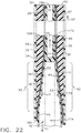
- Method 158 includes employment of pre-cured composite flute core member 26' of FIG. 22 .
- Method 158 includes step 160 of laying up first composite buildup pad 34 onto first composite face sheet 22.
- Step 160 further includes first composite buildup pad 34 having first tapered section 36 with first inclined surface 52 which extends in first direction 47 and having second section 49 which extends from first tapered section 36.
- Second section 49 has second surface 29 which extends in second direction 81, different from first direction 47, toward first end 50 of first composite face sheet 22.
- Method 158 further includes step 162 of positioning cured composite flute core member 26', which includes positioning tapered first portion 42 onto first tapered section 36 of first composite buildup pad 34, with adhesive film portion 164 positioned between tapered first portion 42 and first tapered section 36 of first composite buildup pad 34.
- Step 162 further includes positioning second portion 44, to extend in third direction 11 away from tapered first portion 42, onto first composite face sheet 22 with adhesive film portion 166 positioned between second portion 42 and first composite face sheet 22.
- step 162 includes positioning third portion 51, to extend in the second direction 81, away from the tapered first portion 42, toward the first end 50 of first composite face sheet 22, onto second section 49 of first composite buildup pad 34 with adhesive film portion 168 positioned between third core portion 51 and second section 49 of first composite buildup pad 34.
- adhesive film portions 164, 166 and 168 can be a continuous adhesive film extending between first composite buildup pad 34 and composite flute core member 26' and between first composite face sheet 22 and composite flute core member 26'.
- film portions 164, 166 and 168 can be any number of separate sections of adhesive film extending between first composite buildup pad 34 and composite flute core member 26'and between first composite face sheet 22 and composite flute core member 26'.
- Other constructions of film portions 164, 166 and 168 can include a combination of continuous adhesive film and/or sections of adhesive film as desired.
- Method 158 further includes laying up second composite buildup pad 38 onto cured composite flute core member 26' which includes positioning second composite buildup pad 38 having second tapered section 40 with second inclined surface 64 which extends in fourth direction 53 onto tapered first portion 42 of composite flute core member 26' with adhesive film portion 170 positioned between second tapered section 40 and tapered first portion 40.
- Method 158 further includes positioning second section 55 of second composite buildup pad 38, which extends from second tapered section 40 with third surface 57 which extends in fifth direction 59, different from fourth direction 59, onto third portion 51 of composite flute core member 26' with adhesive film portion 172 positioned between third portion 172 and second section 55 of second composite buildup pad 38.
- Method 158 further includes laying up second composite face sheet 24 onto second composite buildup pad 38 and onto second portion 44 of cured composite flute core member 26' with adhesive film portion 174 positioned between second portion 44 of cured composite flute core member 26' and second composite face sheet 24.
- adhesive film portions 170, 172 and 174 can also be a continuous adhesive film extending between second composite buildup pad 38 and composite flute core member 26' and between second composite face sheet 24 and composite flute core member 26'.
- film portions 170, 172 and 174 can be any number of separate sections of adhesive film extending between first composite buildup pad 34 and composite flute core member 26' and between first composite face sheet 22 and composite flute core member 26'.
- Other constructions of film portions 170, 172 and 174 can include a combination of continuous adhesive film and/or sections of adhesive film as desired.
- Method 158 further includes co-bonding first composite face sheet 22 with second portion 44 of composite flute core member 26'; co-bonding first tapered section 36 of first composite buildup pad 34 with tapered first portion 42 of composite flute core member 26'; co-bonding second composite face sheet 24 with second portion 44 of the composite flute core member 26'; co-bonding second tapered section 40 of second composite buildup pad 38 with tapered first portion 42 of composite flute core member 26'; and co-curing first composite face sheet 22 with first composite buildup pad 34 and second composite face sheet 24 with second composite buildup pad 38.
Landscapes
- Engineering & Computer Science (AREA)
- General Engineering & Computer Science (AREA)
- Mechanical Engineering (AREA)
- Remote Sensing (AREA)
- Aviation & Aerospace Engineering (AREA)
- Chemical & Material Sciences (AREA)
- Combustion & Propulsion (AREA)
- Connection Of Plates (AREA)
- Laminated Bodies (AREA)
Abstract
Description
- This disclosure generally relates to an edge joint for composite materials and more particularly an edge joint and method to assemble an edge joint for composite sandwich shell edges.
- Composite structures are being developed to replace aluminum components for use with space launch vehicles. Replacement of aluminum components with lighter, lower cost, and less thermally conductive composite components will enable larger payloads, reduced operating costs and longer missions due to propellant boil-off reduction.
- In the construction of the composite structures, composite fluted core sandwich shell wall assemblies were employed. These wall assemblies were used, for example, in the construction of an external structural wall assembly of a rocket or in the construction of a cryogenic tank assembly. Sections of the wall assemblies were joined together with joint edge structures so as to connect adjoining sections of the structure being assembled. As higher line load demands are encountered and needed than originally used in smaller rockets or structures positioned higher in a stack, for example, an improved edge joint construction is needed for constructing the structural assembly with composite fluted core sandwich shell wall sections.
- The lighter load shell edge joints originally developed required relatively large openings between intermittently spaced shell edge reinforcements to allow extraction of tooling. As a result of the relatively large openings, that construction did not permit more closely spaced fasteners that would be needed for a joint that needed to carry a higher load capacity. The lighter load shell edge joint construction also forced load into the face sheets of the structure at the ends of the flutes which necessitated positioning a local doubler for carrying higher loads for which the original joint was not designed.
- An improved shell edge joint for a composite fluted core sandwich shell wall is needed and a method to assemble a composite wall assembly edge joint is needed that will provide improved load carrying capabilities such that more load can be carried and distributed permitting additional and more closely spaced fasteners. This improved shell edge joint performance for increased load capacity needs to be accomplished with minimizing the increase in vehicle weight.
- The present invention relates to a composite wall assembly edge joint includes a first composite buildup pad secured to a first composite face sheet. The first composite buildup pad has a first tapered section with a first inclined surface which extends in a first direction and has a second section which extends from the first tapered section with a second surface which extends in a second direction, different from the first direction, toward a first end of the first composite face sheet. The composite wall assembly edge joint also includes a composite flute core member which includes a tapered first portion secured to the first tapered section of the first composite buildup pad; a second portion which extends in a third direction away from the tapered first portion and is secured to the first composite face sheet; and a third portion which extends in the second direction, away from the tapered first portion, toward the first end of the first composite face sheet secured to the second section of the first composite buildup pad.
- The present invention relates to a method for assembling a composite wall assembly edge joint which includes laying up a first composite buildup pad onto a first composite face sheet with the first composite buildup pad having a first tapered section with a first inclined surface which extends in a first direction and having a second section which extends from the first tapered section with a second surface which extends in a second direction, different from the first direction, toward a first end of the first composite face sheet. The method further includes laying up a composite flute core member which includes: positioning a tapered first portion onto the tapered first section of the first composite buildup pad; positioning a second portion, to extend in a third direction away from the first tapered portion, onto the first composite face sheet; and positioning a third portion, to extend in the second direction, away from the first tapered portion, toward the first end of the first composite face sheet and onto the second section of the first composite buildup pad.
- The present invention relates to a method of assembling a composite wall assembly edge joint which includes laying up a first composite buildup pad onto a first composite face sheet with the first composite buildup pad having a first tapered section. The first tapered section has a first inclined surface which extends in a first direction having a second section which extends from the first tapered section with a second surface which extends in a second direction, different from the first direction, toward a first end of the first composite face sheet. The method further includes: positioning a cured composite flute core member which includes positioning a tapered first portion onto the first tapered section of the first composite buildup pad with an adhesive film portion positioned between the first tapered portion and the first tapered section of the first composite buildup pad; positioning a second portion, to extend in a third direction away from the tapered first portion, onto the first composite face sheet with an adhesive film portion positioned between the second portion and the first composite face sheet; and positioning a third portion, to extend in the second direction, away from the tapered first portion, toward the first end of the first composite face sheet, onto the second section of the first composite buildup pad with an adhesive film portion positioned between the third portion and second section of the first composite buildup pad.
-
Clause 1. A composite wall assembly edge joint, comprising:- a first composite buildup pad having a first tapered section is secured to and extends along a first composite face sheet;
- a second composite buildup pad having a second tapered section is secured to and extends along a second composite face sheet, wherein the first and second composite buildup pads are positioned between spaced apart first and second composite face sheets; and
- a composite flute core member comprising:
- a tapered first portion positioned between and secured to the first tapered section and to the second tapered section; and
- a second portion of the composite flute core member extends in a direction away from the tapered first portion of the composite flute core member and is positioned between, extends along and is secured to the first and second composite face sheets.
- Clause 2. A composite wall assembly edge joint of
clause 1, wherein:- the first composite buildup pad extends in a direction away from a first end of the first composite sheet face;
- the first tapered section of the first composite buildup pad has a first inclined surface with a thickness of the first tapered section reducing in dimension as the first composite buildup pad extends in the direction away from the first end;
- the second composite buildup pad extends in a direction away from a second end of the second composite sheet face; and
- the second tapered section of the second composite buildup pad has a second inclined surface with a thickness of the second tapered section reducing in dimension as the second composite buildup pad extends in the direction away from the second end.
-
Clause 3. The composite wall assembly edge joint of any of the preceding clauses, further including a bridge composite structure positioned between the first composite buildup pad and the second composite buildup pad, wherein:- the bridge composite structure is secured to both the first and second build up pads; and
- the bridge composite structure extends along the first composite build up pad in a direction away from the first end of the first composite face sheet and extends along the second composite buildup pad in a direction away from the second end of second composite face sheet.
-
Clause 4. The composite wall assembly edge joint of any of the preceding clauses, edge joint further including the bridge composite structure is post bonded to the first composite build up pad and is post bonded to the second composite build up pad. - Clause 5. The composite assembly edge joint of any of preceding clauses, further including a first hole extending in a first direction through the first composite sheet face, the first composite build up pad, the bridge composite structure, the second composite buildup pad and the second composite face sheet.
- Clause 6. The composite wall assembly edge joint of any of the preceding clauses, further including a first portion of a second hole extending through the bridge composite structure in a second direction transverse to the first direction of the first hole such that the first portion of the second hole is in communication with the first hole and a second portion of the second hole extends within the bridge composite structure in the second direction spaced apart across the first hole and aligned with the first portion of the second hole.
- Clause 7. The composite wall assembly edge joint of any of the preceding clauses, further including a barrel nut having a hole which extends through the barrel nut with the barrel nut positioned within the first hole of the bridge composite structure, wherein:
- the barrel nut having a threaded surface defined by an inner wall surface of the hole; and
- the hole of the barrel nut is positioned aligned with the first and second portions of the second hole of the bridge composite structure.
- Clause 8. The composite wall assembly edge joint of any of the preceding clauses, further including a bolt comprising threads compatible to the threaded surface defined by the inner wall surface of the hole of the barrel nut, wherein:
- the bolt is positioned within the first portion of the second hole of the bridge composite structure; and
- the threads of the bolt engage the threaded surface defined by the inner wall surface of the hole of the barrel nut.
- Clause 9. The composite wall assembly edge joint of any of the preceding clauses, further including:
- the tapered first portion of the flute core member having a first inclined surface relative to the first face sheet and extends along the first inclined surface of the first composite build up pad such that the first inclined surface of the first portion of the composite flute core member is positioned further from the first composite face sheet as the first portion of the composite flute core member extends in a direction toward the first end of the first composite face sheet; and
- the first portion of the composite flute core member having a second inclined surface relative to the second face sheet and extends along a second inclined surface of the second build up pad such that the second inclined surface of the first portion of the composite flute core member is positioned further from second face sheet as the first portion extends in a direction toward the second end of the second composite face sheet.
-
Clause 10. The composite wall assembly edge joint of any of the preceding clauses, further including:- the first portion of the composite flute core member comprising a first wall member with the first inclined surface of the first portion of the composite flute core member positioned on the first wall member and the first portion of the composite flute core member comprising a second wall member with the second inclined surface of the first portion of the composite flute core member positioned on the second wall member; and
- the first wall member and the second wall member are spaced apart and converge as the first wall member extends in the direction of the first end of the first composite face sheet and the second wall member extends in a direction of the second end of the second composite face sheet.
-
Clause 11. The composite wall assembly edge joint of any of the preceding clauses, further including:- the first inclined surface of the tapered first portion of the composite flute core member is co-cured to the first inclined surface of the first composite build up pad;
- the second inclined surface of the first portion of the composite flute core member is co-bonded to the second inclined surface of the second composite build up pad; and
- the second portion of the composite flute core member is co-bonded to the first composite face sheet and to the second composite face sheet.
-
Clause 12. The composite wall assembly edge joint of any of the preceding clauses, further including the first composite build up pad is co-bonded to the first composite face sheet and the second composite build up pad is co-cured to the second composite face sheet. - Clause 13. A method for assembling a composite wall assembly edge joint, comprising the steps of:
- laying up a first composite buildup pad having a first tapered section onto a cured first composite face sheet with an adhesive layer positioned between the first composite buildup pad and the first composite face sheet;
- positioning a composite flute core member, comprising a tapered first portion comprising a first inclined surface and a second inclined surface wherein:
- the first inclined surface of the composite flute core member is positioned onto the first tapered section of the first composite buildup pad; and
- a second portion of the composite flute core member extends from the first portion along first composite face sheet with an adhesive film positioned between the second portion and the first composite face sheet;
- heating at least the first composite buildup pad and the composite flute core member, co-curing the first composite buildup and the composite flute core member securing together the first tapered section of the first composite buildup pad with the first inclined surface of the composite flute core member and co-bonding the second portion of the composite flute core member to the first composite face sheet;
- laying up a second composite buildup pad having a second tapered section wherein the second composite buildup pad is positioned spaced apart from the first composite buildup pad and with at least a portion of the second tapered section of the second composite buildup pad overlying an adhesive film positioned overlying the second inclined surface of the tapered first portion of the composite flute core member; and
- heating at least the second composite build up pad and co-bonding the second composite buildup pad to the second inclined surface of the first portion of the composite flute core member.
-
Clause 14. The method for assembling a composite wall assembly edge joint of clause 13, wherein:- the step of laying up the first buildup pad further including the step of laying up of the first buildup pad which extends in a direction away from a first end of the first composite face sheet and configuring the first tapered section having a first inclined surface with a thickness of the first composite buildup pad reducing in dimension as the first composite buildup pad extends in a direction away from the first end;
- the step of positioning of the composite flute core member further including positioning the first inclined surface of the composite flute core overlying the first inclined surface of the first composite buildup pad such that the first inclined surface of the composite flute core member increases in distance away from the first composite face sheet as the composite flute core member extends in a direction toward the first end of the first composite sheet face; and
- the step of laying up the second composite buildup pad including configuring a second inclined surface of the second composite buildup pad with the second composite buildup pad reducing in thickness as the second composite buildup pad extends in a direction away from the first end of the first composite face sheet with the second inclined surface of the first portion of the composite flute core member decreases in distance from the first composite face sheet as the second inclined surface of the composite flute core member extends in a direction toward the first end of the first composite face sheet.
- Clause 15. The method for assembling a composite wall assembly edge joint of any of the preceding
clauses 13 or 14, wherein the step of laying up the second composite buildup pad further includes a step of laying up a second composite face sheet onto the second composite build-up pad and onto the second portion of the composite flute core member with positioning an adhesive film between the second portion of the composite flute core member and the second composite face sheet. -
Clause 16. The method for assembling a composite wall assembly edge joint of any of the clauses 13-15, wherein the step of heating at least the second composite buildup pad further including co-curing the second composite buildup pad and the second composite face sheet together and co-bonding the second portion of the composite flute core member to the second composite face sheet. - Clause 17. The method for assembling a composite wall assembly edge joint of any of the preceding clauses 13-16, further including the step of laying up a composite bridge structure and post bonding the composite bridge structure to the first and second composite buildup pads.
-
Clause 18. The method for assembling a composite wall assembly edge joint of clause 17, further including the step of drilling a first hole in a first direction through the first composite face sheet, the first composite buildup pad, the composite bridge structure, the second composite buildup pad and the second composite face sheet. - Clause 19. The method for assembling a composite wall assembly edge joint of
clause 18, further including the step of drilling a first portion of a second hole in the composite bridge structure in a direction transverse to the first direction placing the first portion in communication with the first hole and continue drilling a second portion of the second hole spaced apart across the first hole from the first portion of the second hole and aligned with the first portion of the second hole. -
Clause 20. The method for assembling a composite wall assembly edge joint of clause 19, further including the step of inserting a barrel nut into the first hole and inserting a bolt into the second hole and securing the bolt to the barrel nut. - Clause 21. A method for assembling a composite wall assembly edge joint, comprising steps of:
- laying up a first composite face sheet;
- laying up a first composite buildup pad having a first tapered section onto the first composite face sheet;
- positioning a composite flute core member, comprising a tapered first portion comprising a first inclined surface and a second inclined surface wherein:
- the first inclined surface of the composite flute core member is positioned onto the first tapered section of the first composite buildup pad; and
- a second portion of the composite flute core member extends from the tapered first portion along first composite face sheet; and
- laying up a second composite buildup pad having a second tapered section wherein the second composite buildup pad is positioned spaced apart from the first composite buildup pad having at least a portion of the second tapered section of the second composite buildup pad overlying the second inclined surface of the tapered first portion of the composite flute core member.
-
Clause 22. The method for assembling of clause 21, wherein the step of laying up the first buildup pad further including the step of laying up of the first buildup pad to extend in a direction away from a first end of the first composite face sheet with the first tapered section having a thickness reducing in dimension as the first composite buildup pad extends in a direction away from the first end. - Clause 23. The method for assembling of
clause 21 or 22, wherein the step of positioning of the composite flute core member further including positioning the first inclined surface of the composite flute core member overlying the first tapered section of the first composite buildup pad such that the first inclined surface of the composite flute core member increases in distance away from the first composite face sheet as the composite flute core member extends in a direction toward the first end of the first composite sheet face. -
Clause 24. The method for assembling according to any of the clauses 21-23, wherein the step of laying up the second composite buildup pad having the second tapered section includes configuring the second tapered section with the second tapered section reducing in thickness as the second composite buildup pad extends in a direction away from the first end of the first composite face sheet with the second inclined surface of the tapered first portion of the composite flute core member positioned closer to the first composite face sheet as the second inclined surface of the composite flute core member extends in a direction toward the first end of the first composite face sheet. - Clause 25. The method for assembling of any of the preceding clauses 21-24, further including a step of supporting an interior surface of the tapered first portion and the second portion of the composite flute core member.
-
Clause 26. The method for assembling of clause 25, wherein the step of supporting includes a step of inserting a pressurized gas into an interior of the composite flute core member. - Clause 27. The method for assembling of any of the preceding clauses 21-26, wherein the step of supporting including a step of inserting a collapsible support structure into the interior of the composite flute core member supporting the interior surface of the first portion and the second portion of the flute core member.
-
Clause 28. The method for assembling of any of the preceding clauses 21-27, further including a step of positioning a support structure within space between the first composite buildup pad and the second composite buildup pad. -
Clause 29. The method for assembling of any of the preceding clauses 21-28, further including a step of laying up a second composite face sheet onto the second composite buildup pad and onto the second portion of the composite flute core member which extends from the tapered first portion of the composite flute core member. -
Clause 30. The method for assembling ofclause 29, further including a step of heating the first composite face sheet, first composite buildup pad, the composite flute core member; and the second composite buildup pad and the second composite face sheet. -
Clause 31. The method for assembling ofclause 30, further including a step of laying up a composite bridge structure and post bonding the composite bridge structure to the first and second composite buildup pads. -
Clause 32. The method for assembling ofclause 31, further including a step of drilling a first hole in a first direction through the first composite face sheet, the first composite buildup pad, the composite bridge structure, the second composite buildup pad and the second composite face sheet. -
Clause 33. The method for assembling ofclause 32, further including a step of drilling a first portion of a second hole in the composite bridge structure in a second direction transverse to the first direction placing the first portion in communication with the first hole and drilling a second portion of the second hole positioned spaced apart from the first portion of the second hole across the first hole and aligned with the first portion of the second hole. -
Clause 34. The method for assembling ofclause 33, further including a step of inserting a barrel nut into the first hole and inserting a bolt into the second hole and securing the bolt to the barrel nut. -
Clause 35. A method for assembling a composite wall assembly edge joint, comprising steps of:- laying up a composite first face sheet;
- laying up a composite first buildup pad having a first tapered section onto the composite first face sheet;
- positioning a cured composite flute core member, comprising a tapered first portion comprising a first inclined surface and a second inclined surface, wherein
- the first inclined surface of the cured composite flute core member is positioned onto the first tapered section of the for composite buildup pad with an adhesive film positioned between the first inclined surface and first tapered section; and
- a second portion of the composite flute core member extends from the tapered first portion along first composite face sheet wherein an adhesive film is positioned between the second portion of the composite flute core member and the first composite face sheet; and
- laying up a second composite buildup pad having a second tapered section wherein the second composite buildup pad is positioned spaced apart from the first composite buildup pad having at least a portion of the second tapered section overlying the second inclined surface of the tapered first portion of the composite flute core member with an adhesive layer positioned between the second tapered section and the second inclined surface of the tapered first portion of the composite flute core member.
-
Clause 36. The method for assembling ofclause 35, further including a step of positioning a support structure between the spaced apart first composite buildup pad and the second composite buildup pad. -
Clause 37. The method for assembling of any of the precedingclauses -
Clause 38. The method for assembling ofclause 37, further including a step of heating the first composite face sheet, the first composite buildup pad, the composite flute core member, the second composite buildup pad and the second composite face sheet. -
Clause 39. The method for assembling ofclause 38, further including a step of laying up a composite bridge structure and post bonding the composite bridge structure to the first and second composite buildup pads. -
Clause 40. The method for assembling ofclause 39, further including steps of:- drilling a first hole in a first direction through the first composite face sheet, the first composite buildup pad, the composite bridge structure, the second composite buildup pad and the second composite face sheet;
- drilling a first portion of a second hole in the composite bridge structure in a second direction transverse to the first direction placing the first portion in communication with the first hole and drilling a second portion of the second hole positioned spaced apart from the first portion of the second hole across the first hole and aligned with the first portion of the second hole; and
- inserting a barrel nut into the first hole and inserting a bolt into the second hole and securing the bolt to the barrel nut.
-
Clause 41. A method of for assembling a composite wall assembly edge joint, comprising:- laying up a first composite buildup pad onto a first composite face sheet with the first composite buildup pad having a first tapered section with a first inclined surface which extends in a first direction and having a second section which extends from the first tapered section with a second surface which extends in a second direction, different from to the first direction, toward a first end of the first composite face sheet; and
- positioning a cured composite flute core member which includes:
- positioning a tapered first portion onto the first tapered section of the first composite buildup pad with an adhesive film portion positioned between the tapered first portion and the first tapered section of the first composite buildup pad;
- positioning a second portion, to extend in a third direction away from the tapered first portion, onto the first composite face sheet with an adhesive film portion positioned between the second portion and the first composite face sheet; and
- positioning a third portion, to extend in the second direction, in a direction away from the tapered first portion, toward the first end of the first composite face sheet, onto the second section of the first composite buildup pad with an adhesive film portion positioned between the third core portion and second section of the first composite buildup pad.
-
Clause 42. The method for assembling a composite wall assembly edge joint ofclause 41, further including- laying up a second composite buildup pad onto the cured composite flute core member, comprising:
- positioning the second composite buildup pad having a second tapered section with a second inclined surface which extends in a fourth direction onto the tapered first portion of the composite flute core member with an adhesive film portion positioned between the second tapered section and the tapered first portion; and
- positioning a second section of the second composite buildup pad which extends from the second tapered section with a third surface which extends in a fifth direction, different from the fourth direction, onto the third portion of the composite flute core member with adhesive film portion positioned between the third portion and the second section of the second composite buildup pad.
- laying up a second composite buildup pad onto the cured composite flute core member, comprising:
-
Clause 43. The method for assembling a composite wall assembly edge joint ofclause 42, further includes laying up a second composite face sheet onto the second composite buildup pad and onto the second portion of the cured composite flute core member with an adhesive film portion positioned between the second portion of the cured composite flute core member and the second composite face sheet. -
Clause 44. The method for assembling a composite wall assembly edge joint ofclause 43, further including- co-bonding the first composite face sheet with the second portion of the composite flute core member;
- co-bonding first tapered section of the first composite buildup pad with the tapered first portion of the composite flute core member;
- co-bonding the second composite face sheet with the second portion of the composite flute core member;
- co-bonding the second tapered section of the second composite buildup pad with the tapered first portion of the composite flute core member; and
- co-curing the first composite face sheet with the first composite buildup pad and the second composite face sheet with the second composite buildup pad.
-
-
FIG. 1 is a schematic perspective view of a rocket showing an edge joint location on wall of rocket; -
FIG. 2 is a partial cut away perspective view of a cross section of the rocket shown inFIG. 1 with a cryogenic propellant tank on board; -
FIG. 3 is a an enlarged partial cut away view of the joint edge of a composite wall assembly of that which is encircled and designated as 3 inFIG. 2 ; -
FIG. 4 is cross section view taken along line 4-4 inFIG. 3 ; -
FIG. 5 is a perspective view of a composite flute core member of the composite wall assembly shown inFIG. 3 ; -
FIG. 6 is an enlarged partially cut away view of tapered end of the composite flute core member inFIG. 5 ; -
FIG. 7 is a cross section view of the joint edge of the composite wall assembly as seen along line 7-7 inFIG. 3 ; -
FIG. 8 is a perspective view of cross section as taken along line 4-4 ofFIG. 3 ; -
FIG. 8A is an enlarged view of that which is encircled as 8A inFIG. 8 ; -
FIG. 9 is a flow chart for a method for assembling a composite wall assembly edge joint; -
FIG. 10 is a flow chart for a second example of a method for assembling a composite wall assembly edge joint; -
FIG. 11 is a cross section view of the joint edge of the composite wall assembly as seen along line 7-7 inFIG. 3 wherein this joint edge is assembled in accordance with the second example of the method for assembling a composite wall assembly edge joint as set forth inFIG. 10 ; -
FIG. 12 is the cross section as shown inFIG. 4 wherein the composite flute core member is supported with a collapsible support during layup of an edge joint assembly for the second example of the method for assembling the composite wall assembly edge joint; -
FIG. 13 is a cross section view showing the providing of support between spaced apart first and second composite buildup pads during assembly of edge joint; -
FIG. 14 is a flow chart for a third example of a method for assembling a composite wall assembly edge joint; and -
FIG. 15 is an enlarged view of that which is encircled as 8A inFIG. 8 showing an edge joint assembled in accordance with the third example of the method for assembling a composite wall assembly edge joint as set forth inFIG. 14 ; -
FIG. 16 is a cross section of the composite wall assembly edge joint which has been co-cured along line 16-16 as seen inFIG. 17 ; -
FIG. 17 is an exploded perspective view of the composite wall assembly edge joint; -
FIG. 18 is an exploded perspective view of the composite wall assembly edge joint exploded in a vertical and in a horizontal direction, without third and fourth composite build up pads and without first and second composite face sheets ofFIG. 17 ; -
FIG. 19 is a partially exploded end view of the composite wall assembly edge joint ofFIG. 17 with first and second composite face sheets added; -
FIG. 20 is a flow chart for a method for assembling the composite wall assembly edge joint which will be co-cured, ofFIG. 16 ; -
FIG. 21 is a flow chart for a method for assembling the composite wall assembly edge joint which includes co-bonding a pre-cured composite flute core member within the composite wall assembly edge joint ofFIG. 22 ; and -
FIG. 22 is a cross section of another example of the composite wall assembly edge joint with the composite flute core member pre-cured. - As mentioned earlier, composite structures are being developed to replace aluminum components or structures for use with a space launch vehicle or
rocket 10, such as shown inFIGS. 1 and 2 . Replacement of aluminum components with lighter, lower cost, and less thermally conductive composite components will enable larger payloads, reduced operating costs and longer missions due to propellant boil-off reduction. - In the construction of the composite components or structures, an example of such components or structures include using composite fluted core sandwich shell wall assemblies. These wall assemblies are used, for example, in the construction of different portions of rocket or
launch vehicle 10 such as for an externalstructural wall assembly 12 ofrocket 10, or in another example for a cryogenic propellant tank with askirt assembly 14, as seen inFIGS. 1 and 2 , respectively. Other components of various versions ofrocket 10 can also be constructed with composite structures such as, an inter stage section for a multiple stage rocket as well as for other portions of a rocket. As mentioned above, an example of assembling a composite sandwichshell wall assembly 12 with an improvedjoint edge 16 will be discussed herein. Improvedjoint edge 16 joins together, in this example,first section 18 tosecond section 20 ofwall assembly 12 and will provide improved performance for higher line load demands with minimizing weight increase in vehicle orrocket 10. - In referring to
FIG. 3 , edge joint 16 is shown connectingfirst section 18 tosecond section 20 ofwall assembly 12. Composite fluted core sandwichshell wall assembly 12 includes first or inboardcomposite face sheet 22 and spaced apart second or outboardcomposite face sheet 24. Positioned within the spaced apart first and secondcomposite face sheets composite core members 26. An example of flutecomposite core member 26 is shown inFIGS. 5 and 6 . In this example ofwall assembly 12, flutecomposite core members 26 are trapezoidal in shape, as seen inFIG. 4 however the shape can be selected from one of a number of shapes. In this example, trapezoidal shaped flutecomposite core members 26 are positioned between first and secondcomposite face sheets core assembly 28, as seen inFIG. 4 . Flutecomposite core members 26 can be further reinforced with employing anoodle 30 structure positioned in acavity 32 that forms betweenadjacent radiuses composite core members 26 and firstcomposite face sheet 22, as well as, betweenadjacent radiuses composite core members 26 and secondcomposite face sheet 24.Wall assembly 12 withcore assembly 28 provides a strong and lightweight construction. - In referring to
FIGS. 5-8A , composite fluted coresandwich wall assembly 12 with edge joint 16 is shown which accommodates higher line load demands exerted through edge joint 16, whether exerted in compression or in tension. In referring toFIG. 7 , firstcomposite buildup pad 34 having first taperedsection 36 is secured to and extends along first or inboardcomposite face sheet 22. Secondcomposite buildup pad 38 having a secondtapered section 40 is secured to and extends along second or outboardcomposite face sheet 24. First and secondcomposite buildup pads composite face sheets flute core member 26 includes taperedfirst portion 42 and is positioned between and secured to firsttapered section 36 and to secondtapered section 40.Second portion 44, as seen inFIG. 5 , of compositeflute core member 26 is positioned between, extends along and is secured to first and secondcomposite face sheets Second portion 44 of compositeflute core member 26 extends indirection 46 away fromfirst portion 42. This construction of taperedfirst portion 42 of flutecomposite core member 26 being secured to first and secondtapered sections composite buildup pads joint edge 16. - As seen in
FIGS. 7 ,8 and8A , firstcomposite buildup pad 34 extends in adirection 48 away fromfirst end 50 of first or inboardcomposite sheet face 22. First taperedsection 36 of firstcomposite buildup pad 34 has first inclinedsurface 52 with a thickness T of firsttapered section 36 reducing in dimension as firstcomposite buildup pad 34 extends indirection 48 away fromfirst end 50. Secondcomposite buildup pad 38 extends indirection 54 away fromsecond end 56 of second or outboardcomposite sheet face 24. Second taperedsection 40 of secondcomposite buildup pad 38 has second inclinedsurface 64 with thickness T' of secondtapered section 40 reducing in dimension as secondcomposite buildup pad 38 extends indirection 54 away fromsecond end 56. -
First portion 42 offlute core member 26 has first inclinedsurface 58 relative to firstcomposite face sheet 22.Inclined surface 58 extends along firstinclined surface 52 of first composite build uppad 34 such that firstinclined surface 58 offirst portion 42 of compositeflute core member 26 is positioned further from firstcomposite face sheet 22 asfirst portion 42 of compositeflute core member 26 extends indirection 60 towardfirst end 50 of firstcomposite face sheet 22.First portion 42 of compositeflute core member 26 has second inclinedsurface 62 relative to second oroutboard face sheet 24 which extends along secondinclined surface 64 of the second build uppad 38 such that secondinclined surface 62 offirst portion 42 of compositeflute core member 26 is positioned further from second oroutboard face sheet 24 asfirst portion 42 extends indirection 66 towardsecond end 56 of secondcomposite face sheet 24. - As seen in
FIGS. 5 and 6 ,first portion 42 of compositeflute core member 26 includesfirst wall member 68 with firstinclined surface 58 offirst portion 42 of compositeflute core member 26 positioned onfirst wall member 68.First portion 42 of compositeflute core member 26 includessecond wall member 70 with secondinclined surface 62 offirst portion 42 of compositeflute core member 26 is positioned onsecond wall member 70.First wall member 68 andsecond wall member 70 are spaced apart a as seen for example as distance D, as seen inFIG. 6 , and converge asfirst wall member 68 extends indirection 60 offirst end 50 of firstcomposite face sheet 22, as seen inFIG. 7 , andsecond wall member 70 extends indirection 66 ofsecond end 56 of the secondcomposite face sheet 24. - As seen in
FIGS. 5-8A , first inclinedsurface 58 offirst portion 42 of compositeflute core member 26 is co-cured to firstinclined surface 52 of first composite build uppad 34. Secondinclined surface 62 of thefirst portion 42 of the compositeflute core member 26 is co-bonded to the secondinclined surface 64 of second composite build uppad 38.Second portion 44 of compositeflute core member 26 is co-bonded to firstcomposite face sheet 22 and to secondcomposite face sheet 24. First composite build uppad 34 is co-bonded to firstcomposite face sheet 22 and second composite build uppad 38 is co-cured to secondcomposite face sheet 24. - In referring to
FIGS. 7 ,8 and8A , bridgecomposite structure 72 is positioned between firstcomposite buildup pad 34 and secondcomposite buildup pad 38. Bridgecomposite structure 72 is secured to both first and second build uppads composite buildup pad 34 indirection 48 away fromfirst end 50 of firstcomposite face sheet 22 and extends along secondcomposite buildup pad 38 indirection 54 away fromsecond end 56 of secondcomposite face sheet 24. - Bridge
composite structure 72, in this example, is post bonded to first composite build uppad 34 and is post bonded to second composite build uppad 38. Further included isfirst hole 74 which extends infirst direction 76 through firstcomposite sheet face 22, first composite build uppad 34, bridgecomposite structure 72, secondcomposite buildup pad 38 and secondcomposite face sheet 24.First portion 78 ofsecond hole 80 extends through bridgecomposite structure 72 insecond direction 82 transverse tofirst direction 76 offirst hole 74 such thatfirst portion 78 ofsecond hole 80 is in communication withfirst hole 74 andsecond portion 84 ofsecond hole 80 extends within bridgecomposite structure 72 insecond direction 82 spaced apart acrossfirst hole 74 and aligned withfirst portion 78 ofsecond hole 80. - Further included is
barrel nut 86 havinghole 88, which extends throughbarrel nut 86, withbarrel nut 86 positioned withinfirst hole 74 of bridgecomposite structure 72.Barrel nut 86 has threadedsurface 90 defined byinner wall surface 92 ofhole 88 withhole 88 ofbarrel nut 86 positioned aligned with first andsecond portions second hole 80 of bridgecomposite structure 72.Bolt 94 includesthreads 96 compatible to threadedsurface 90 defined by theinner wall surface 92 ofhole 88 ofbarrel nut 86.Bolt 94 is positioned withinfirst portion 78 ofsecond hole 80 of bridgecomposite structure 72.Threads 96 ofbolt 94 engage threadedsurface 90 defined byinner wall surface 92 ofhole 88 ofbarrel nut 86. Withbolt 94 engaged and tightened, as seen inFIG. 7 ,first section 18 is secured tosecond section 20 ofwall assembly 12. - As will be appreciated in the discussion of an example of the assembly of edge joint 16,
composite bridge structure 72 will be installed as a latter element in thejoint edge 16 construction which includes the components of first composite orinboard sheet face 22, firstcomposite buildup pad 34, flutecomposite core member 26, secondcomposite buildup pad 38 and second composite oroutboard face sheet 24. With these components assembledcomposite bridge structure 72 is installed alongwall assembly 12.Composite bridge structure 72 can provide the fabricator as needed a substantially continuous wall which extends aboutwall assembly 12 in which to drillsecond holes 80 with intersecting corresponding first holes 74. With a substantially continuous wall established by bridgecomposite structure 72, the fabricator has the flexibility of selectively spacing connecting assemblies ofbarrel nuts 86 andbolts 94 alongjoint edge 16 ofwall assembly 12 to accommodate load demands as needed throughjoint edge 16 alongwall assembly 12 in connecting, for example,section 18 tosection 20 ofwall assembly 12. As a result, the fabricator selects the spacing and employs the spacing, as can be seen for example inFIG. 3 , as required for load transference acrossjoint edge 16. The load lines will extend along first andsecond buildup pads tapered sections second walls flute core member 26 and in turn extend into first andsecond face sheets joint edge 16 with an enhanced performance forwall assembly 12. - In referring to
FIG. 9 , an example ofmethod 100 for assembling composite fluted core sandwichshell wall assembly 12 edge joint 16 is shown.Method 100 includesstep 102 of laying up firstcomposite buildup pad 34 having a firsttapered section 36 onto a cured first composite orinboard face sheet 22, with anadhesive layer 43, as seen inFIG. 8A , positioned between firstcomposite buildup pad 34 and firstcomposite face sheet 22. Step 102 of laying upfirst buildup pad 34 further includes the step of laying up offirst buildup pad 34 which extends in adirection 48 away fromfirst end 50 of firstcomposite face sheet 22 and configuring first taperedsection 36 having first inclinedsurface 52 with thickness T of firstcomposite buildup pad 34 reducing in dimension as firstcomposite buildup pad 34 extends indirection 48 away fromfirst end 50. -
Method 100 further includesstep 104 of positioning compositeflute core member 26, which includes taperedfirst portion 42, having a firstinclined surface 58 and a secondinclined surface 62, wherein, first inclinedsurface 58 of compositeflute core member 26 is positioned onto firsttapered section 36 of firstcomposite buildup pad 34.Second portion 44 of compositeflute core member 26, as seen inFIG. 5 , extends indirection 46 away fromfirst portion 42 along first composite orinboard face sheet 22, as seen inFIGS. 7 and8A , withadhesive film 43 positioned betweensecond portion 44 of flutecomposite core member 26 and firstcomposite face sheet 22. Step 104 of positioning of compositeflute core member 26 further includes positioning firstinclined surface 58 ofcomposite flute core 26 overlying first inclinedsurface 52 of firstcomposite buildup pad 34 such that firstinclined surface 58 of compositeflute core member 26 increases in distance away from firstcomposite face sheet 22 as compositeflute core member 26 extends in adirection 60 towardfirst end 50 of firstcomposite sheet face 22. -
Method 100 further includesstep 106 of heating at least firstcomposite buildup pad 34 and compositeflute core member 26, co-curing firstcomposite buildup pad 34 and compositeflute core member 26 and securing together first taperedsection 36 of firstcomposite buildup pad 34 with firstinclined surface 58 of compositeflute core member 26 and co-bondingsecond portion 44 of compositeflute core member 26 to first composite orinboard face sheet 22. At the same time, first composite build uppad 34 is co-bonded to firstcomposite face sheet 22. -
Method 100 further includesstep 108 of laying up secondcomposite buildup pad 38 having a second tapered section wherein the second composite buildup pad is positioned spaced apart from firstcomposite buildup pad 34 and with at least a portion of the second tapered section of secondcomposite buildup pad 38 overlying anadhesive film 39, as seen inFIG. 8A , positioned overlying secondinclined surface 62 offirst portion 42 of compositeflute core member 26. Step 108 of laying up secondcomposite buildup pad 38 includes configuring secondinclined surface 64 of secondcomposite buildup pad 38 with secondcomposite buildup pad 38 reducing in thickness T' as secondcomposite buildup pad 38 extends indirection 54 away fromsecond end 56 of secondcomposite face sheet 24 with secondinclined surface 62 offirst portion 42 of compositeflute core member 26 decreases in distance from firstcomposite face sheet 22 as secondinclined surface 62 of compositeflute core member 26 extends indirection 60 towardfirst end 50 of firstcomposite face sheet 22. - With second
composite buildup pad 38 positioned overlying secondinclined surface 62 of compositeflute core member 26step 110 is employed of heating at least secondcomposite buildup pad 38 and co-bonding secondcomposite buildup pad 38 to secondinclined surface 62 offirst portion 42 of compositeflute core member 26. - Step 108 of laying up second
composite buildup pad 38 further includes the step of laying up a secondcomposite face sheet 24 onto second composite build-up pad 38 and ontosecond portion 44 of compositeflute core member 26 with positioningadhesive film 39 betweensecond portion 44 of compositeflute core member 26 and secondcomposite face sheet 24, as seen inFIG. 8A . Step 110 of heating at least secondcomposite buildup pad 38 further includes co-curing secondcomposite buildup pad 38 and secondcomposite face sheet 24 together and co-bondingsecond portion 44 of compositeflute core member 26 to secondcomposite face sheet 24. -
Method 100 further includes a step of laying upcomposite bridge structure 72 and post bondingcomposite bridge structure 72 to first and secondcomposite buildup pads adhesive film 41, as seen inFIG. 8A .Adhesive film 41 is positioned betweencomposite bridge structure 72 and first composite build uppad 36 and betweencomposite bridge structure 72 and secondcomposite buildup pad 38. - With
composite bridging structure 72 post bonded to first and secondcomposite buildup pads composite bridge structure 72 further includes a step of drillingfirst hole 74 in afirst direction 76 through firstcomposite face sheet 22, firstcomposite buildup pad 34,composite bridge structure 72, secondcomposite buildup pad 38 and secondcomposite face sheet 24. The step of laying up thecomposite bridge structure 72 further includes a step of drillingfirst portion 78 ofsecond hole 80 incomposite bridge structure 72 in adirection 82 transverse tofirst direction 76 placingfirst portion 78 in communication withfirst hole 74 and continue drillingsecond portion 84 ofsecond hole 80 spaced apart acrossfirst hole 74 fromfirst portion 78 ofsecond hole 80 and aligned withfirst portion 78 ofsecond hole 80. Withfirst hole 74 andsecond hole 80 drilled, the step of laying upcomposite bridge structure 72 further includes a step of insertingbarrel nut 86 intofirst hole 74 and insertingbolt 94 intosecond hole 80 and securingbolt 94 tobarrel nut 86. With securement ofbolt 94,first section 18 andsecond section 20 ofwall assembly 12 are secured together as seen inFIG. 7 . - A second example of a method for assembling a
composite wall assembly 12 edge joint 16 includesmethod 200, as set forth inFIG. 10 . The components of the assembly ofcomposite wall assembly 12 edge joint 16 fabricated undermethod 200 that are common to previously described components for the assembling ofcomposite wall assembly 12 edge joint 16 fabricated undermethod 100 are similarly numbered. As will be appreciated herein, the assembly fabricated under the second example of a method ormethod 200, in contrast to the assembly fabricated undermethod 100, the components ofcomposite wall assembly 12 edge joint 16 undermethod 200 are co-cured. - In referring to
FIG. 10 ,method 200 for assembling acomposite wall assembly 12 edge joint 16, includesstep 202 of laying up firstcomposite face sheet 22, as seen inFig. 11 . In this example, firstcomposite face sheet 22 is an inboard face sheet of this assembly.Method 200 further includesstep 204 of laying up a firstcomposite buildup pad 34 having a firsttapered section 36 onto firstcomposite face sheet 22. Step 206 includes positioning compositeflute core member 26 which includes taperedfirst portion 42 with firstinclined surface 52 and secondinclined surface 64. Firstinclined surface 58 of compositeflute core member 26 is positioned onto firsttapered section 36 of firstcomposite buildup pad 34.Second portion 44 of compositeflute core member 26 extends from taperedfirst portion 42 along firstcomposite face sheet 22. -
Method 200 further includesstep 208 of laying up secondcomposite buildup pad 38 having second taperedsection 40. Secondcomposite buildup pad 38 is positioned spaced apart from firstcomposite buildup pad 34 having at least a portion of secondtapered section 40 of secondcomposite buildup pad 38 overlying secondinclined surface 62 of taperedfirst portion 42 of compositeflute core member 26. - Step 204 of laying up
first buildup pad 34 further includes the step of laying up offirst buildup pad 34 to extend in a direction away fromfirst end 50 of firstcomposite face sheet 22 with firsttapered section 36 having first inclinedsurface 52 with first tapered section having a thickness T reducing in dimension as firstcomposite buildup pad 34 extends indirection 48 away fromfirst end 50. - Step 206 of positioning of composite
flute core member 26 further includes positioning firstinclined surface 58 of compositeflute core member 26 overlying first taperedsection 36 having a firstinclined surface 52 of firstcomposite buildup pad 34, such that firstinclined surface 58 of compositeflute core member 26 increases in distance away from firstcomposite face sheet 22 as compositeflute core member 26 extends indirection 60 towardfirst end 50 of firstcomposite sheet face 22. - Step 208 of laying up second
composite buildup pad 38 having second taperedsection 40 including configuring second taperedsection 40 having a secondinclined surface 64 with second tapered section reducing in thickness T' as secondcomposite buildup pad 38 extends in adirection 54 away fromfirst end 50 of firstcomposite face sheet 22. Secondinclined surface 62 of taperedfirst portion 42 of compositeflute core member 26 is positioned closer to firstcomposite face sheet 22 as secondinclined surface 62 of compositeflute core member 26 extends indirection 66 towardfirst end 50 of firstcomposite face sheet 22. -
Method 200 further includes a step of laying up secondcomposite face sheet 24 onto secondcomposite buildup pad 38 and ontosecond portion 44 of compositeflute core member 26.Second portion 44 of compositeflute core member 26 extends from taperedfirst portion 42 of compositeflute core member 26. - In fabricating composite joint edge assembly16 under
method 200, the composite material will be supported during the assembling of the composite material and co-curing of joint edge assembly16. The supporting of the composite material will maintain the composite material in alignment and free from distortion that would otherwise be imparted to the composite material by the weight of the composite material prior to the composite material being cured. Support will be provided withininterior 61 of compositeflute core member 26 and within spacing 73 between first composite build uppad 34 and second composite build uppad 38, seen for example inFIG. 13 . - In supporting composite
flute core member 26, support is provided withininterior 61 on opposingsurfaces 63 of taperedfirst portion 42, opposingsurfaces 65 ofsecond portion 44 of compositeflute core member 26 as well as opposingsurfaces 79 on opposing side walls, as seen inFIG. 12 . One example of supporting compositeflute core member 26 includes a step of inserting pressurized gas intointerior 61 of compositeflute core member 26.Interior 61 is sealed off, not shown, and an access can be provided to interior 61 to adjust the pressurization within interior 61 as needed. The pressurized gas can be released frominterior 61 of compositeflute core member 26 when the co-curing process is completed. The pressurized gas can, as in this example, leaveinterior 61 of compositeflute core member 26 and pass throughspace 73, as seen inFIG. 13 , between first composite build uppad 34 and second composite build uppad 38. - Another example of supporting of composite
flute core member 26 includes a step of inserting acollapsible support structure 67, as schematically shown inFIG. 12 , intointerior 61 of compositeflute core member 26.Collapsible support structure 67 can be inserted in a collapsed position throughspace 73 positioned between first composite build uppad 34 and second composite build uppad 38 and through opening 69 of taperedfirst portion 42 of compositeflute core member 26. Withcollapsible support structure 67 positioned withininterior 61 of compositeflute core member 26,collapsible support assembly 67 can be deployed such thatplates 75 are positioned and provide support against interior 61surface 65 positioned on opposing sides of compositeflute core member 26 insecond portion 44 of compositeflute core member 26 as seen inFIGS. 11 and12 .Collapsible support assembly 67, insecond portion 44 of compositeflute core member 26 also includesplates 77 positioned in supporting position against interior 61surface 79 positioned on opposing sides of compositeflute core member 26 as seen inFIG. 12 . Other plates of collapsible support assembly 67 (not shown) are positioned againstinterior surface 63 on opposing sides of taperedfirst portion 42 of compositeflute core member 26 to provide support to taperedfirst portion 42 during assembly and co-curing. At the completion of co-curingcollapsible support assembly 67 is collapsed and reduced in profile.Collapsible support assembly 67 is removed or otherwise pulled frominterior 61 of compositeflute core member 26 through opening 69 of compositeflute core member 26 and then out of edge joint 16 throughspace 73 between first composite build uppad 34 and second composite build uppad 38. Removal ofcollapsible support assembly 67 throughspace 73 is accomplished with any obstructions inspace 73 removed as needed. This is also the case with the removal of collapsible support from within taperedfirst portion 42 of compositeflute core member 26 as needed. - Similarly support is needed to be positioned between first composite build up
pad 34 and second composite build uppad 38 during assembling of edge joint 16 and during co-curing of edge joint 16. In referring toFIG. 13 asecond support assembly 71 is positioned between first composite build uppad 34 and second composite build uppad 38.Second support assembly 71 is collapsible and can be inserted intospace 73 in a collapsed or reduced profile and then extended and positioned against first composite build uppad 34 and second composite build uppad 38. At the time of completion of co-curingsecond support assembly 71, in this example, can be collapsed or reduced in profile and pulled out ofspace 73 and from edge joint 16. - The supporting, as discussed above, of the composite material in assembly of edge joint 16, permits the fabricator to maintain the composite material in alignment and undistorted during the assembly and through the desired co-curing process. With the support being provided by a collapsible structure or by a gas which can be released, the support can be removed from the interior of edge joint 16. In this example,
space 73 that is provided between first composite build uppad 34 and second composite build uppad 38 withsecond support assembly 71 removed,space 73 provides the fabricator the opportunity to secure bridgecomposite structure 72, as will be discussed, between first composite build uppad 34 and second composite build uppad 38. With bridgecomposite structure 72 secured and positioned along edge joint 16, the fabricator can space bolts, as described herein, along bridgecomposite structure 72 as desired. The spacing of bolts along edgejoint assembly 16 can provide enhanced load carrying capability with closer spacing of bolts, for example, with bolts connectingfirst section 18 andsecond section 20 ofwall assembly 12. This enhanced load carrying capability is further supported with the transference of the load to the first andsecond buildup pads flute core members 26 and to first and secondcomposite face sheets -
Method 200 further includes a step of heating and co-curing firstcomposite face sheet 22, firstcomposite buildup pad 34, compositeflute core member 26; secondcomposite buildup pad 38 and secondcomposite face sheet 24. In this example, where a circular construction of a rocket is being assembled, sections of edge joint 16 are assembled in sections up to approximately twenty degrees of the circumference of the rocket structure. - With the co-curing accomplished for edge joint 16,
method 200 further includes a step of laying upcomposite bridge structure 72 and post bondingcomposite bridge structure 72 to first and secondcomposite buildup pads pads FIG. 11 . -
Method 200 further includes a step of drillingfirst hole 74 which extends infirst direction 76 through firstcomposite face sheet 22, firstcomposite buildup pad 34,composite bridge structure 72, secondcomposite buildup pad 38 and through secondcomposite face sheet 24. Further included is a step of drillingfirst portion 78 ofsecond hole 80 incomposite bridge structure 72 insecond direction 82 transverse tofirst direction 76 placingfirst portion 76 in communication withfirst hole 74. Drilling further includes drillingsecond portion 84 ofsecond hole 80 positioned spaced apart fromfirst portion 76 ofsecond hole 80 across thefirst hole 74 and aligned withfirst portion 78 ofsecond hole 80. - With
first hole 74 andsecond hole 80 completedmethod 200 further includes a step of insertingbarrel nut 86 intofirst hole 74 and insertingbolt 94 intosecond hole 80 and securingbolt 94 tobarrel nut 86. - A third example of a method for assembling a
composite wall assembly 12 edge joint 16 includesmethod 300, as set forth inFIG. 14 . The components of the assembly ofcomposite wall assembly 12 edge joint 16 fabricated undermethod 300 that are common to previously described components for the assembling ofcomposite wall assembly 12 edge joint 16 fabricated undermethods method 300, in contrast to the assembly fabricated undermethod 200, the elements ofcomposite wall assembly 12 edge joint 16 undermethod 300 employ a cured compositeflute core member 26 in assembling edge joint 16. - In referring to
FIG. 14 ,method 300 for assemblingcomposite wall assembly 12 edge joint 16, includesstep 302 of laying up compositefirst face sheet 22, as seen inFig. 15 . In this example, compositefirst face sheet 22 is an inboard face sheet of this assembly.Method 300 further includesstep 304 of laying up a firstcomposite buildup pad 34 having a firsttapered section 36 onto compositefirst face sheet 22. Step 306 includes positioning cured compositeflute core member 26 which includes taperedfirst portion 42 with firstinclined surface 52 and secondinclined surface 64. Firstinclined surface 52 of cured compositeflute core member 26 is positioned onto firsttapered section 36 with adhesive film 45 positioned between firstinclined surface 52 and firsttapered section 36.Second portion 44 of compositeflute core member 26 extends from taperedfirst portion 42 along firstcomposite face sheet 22 wherein adhesive film 45 is positioned betweensecond portion 44 of compositeflute core member 26 and compositefirst face sheet 22.Method 300 further includesstep 308 laying up secondcomposite buildup pad 38 having second taperedsection 40 wherein secondcomposite buildup pad 38 is positioned spaced apart from firstcomposite buildup pad 34 having at least a portion of secondtapered section 40 overlying secondinclined surface 64 of taperedfirst portion 42 of compositeflute core member 26 withadhesive layer 39 positioned between secondtapered section 40 and secondinclined surface 64 of taperedfirst portion 42 of compositeflute core member 26. -
Method 300 further includes a step of positioningsupport structure 71 between spaced apart firstcomposite buildup pad 34 and secondcomposite buildup pad 38, as seen inFIG. 13 .Method 300 further includes a step of laying up a secondcomposite face sheet 24 onto second composite build uppad 38 and in overlying relationship withsecond portion 44 of cured compositeflute core member 26 withadhesive film 39, as seen inFIG. 15 , positioned between secondcomposite face sheet 24 andsecond portion 44 of compositeflute core member 26. -
Method 300 further includes a step of heating firstcomposite face sheet 22, firstcomposite buildup pad 34, compositeflute core member 26, secondcomposite buildup pad 38 and secondcomposite face sheet 24.Method 300 further includes a step of laying upcomposite bridge structure 72 and post bondingcomposite bridge structure 72 to first and secondcomposite buildup pads -
Method 300 further includes, in this example, drillingfirst hole 74 infirst direction 76, as seen for example inFIG. 11 , through compositefirst face sheet 22, firstcomposite buildup pad 34,composite bridge structure 72, secondcomposite buildup pad 38 and secondcomposite face sheet 24, as seen inFIG. 15 . Further included is drillingfirst portion 78, as seen for example inFIG. 11 , ofsecond hole 80 incomposite bridge structure 72 insecond direction 82 transverse tofirst direction 76 placingfirst portion 78 in communication withfirst hole 74 and drillingsecond portion 84 ofsecond hole 80 positioned spaced apart fromfirst portion 78 ofsecond hole 80 acrossfirst hole 74 and aligned withfirst portion 78 ofsecond hole 80.Method 300 further includes insertingbarrel nut 86 intofirst hole 74 and insertingbolt 94 intosecond hole 80 and securingbolt 94 tobarrel nut 86. - Another example of a
composite wall assembly 12 edge joint 10' will be discussed herein and seen inFIGS. 16-22 . This example of joint edge 10' provides a robust edge joint 10' and provides ease in manufacturing the same.Composite wall assembly 12 edge joint 10', as seen for example inFIG. 16 , includes firstcomposite buildup pad 34 secured to firstcomposite face sheet 22 with the firstcomposite buildup pad 34 having a firsttapered section 36 with a firstinclined surface 52. Firstinclined surface 52 of firsttapered section 36 extends infirst direction 47 and firstcomposite buildup pad 34 hassecond section 49 which extends from first taperedsection 36 withsecond surface 29 which extends insecond direction 81, different fromfirst direction 47, towardfirst end 50 of firstcomposite face sheet 22. Compositeflute core member 26, further includes taperedfirst portion 42 secured to firsttapered section 36 of firstcomposite buildup pad 34. Compositeflute core member 26 further includessecond portion 44 which extends inthird direction 11 away from taperedfirst portion 42 and is secured to firstcomposite face sheet 22. Additionally,third portion 51, of compositeflute core member 26, extends in the second direction, away from taperedfirst portion 42, toward thefirst end 50 of firstcomposite face sheet 22 and is secured tosecond section 49 of firstcomposite buildup pad 34. -
Composite wall assembly 12 edge joint 16 further includes secondcomposite buildup pad 38 secured to secondcomposite face sheet 24, wherein the first and secondcomposite face sheets composite buildup pad 38. Secondcomposite buildup pad 38 has second taperedsection 40 with a secondinclined surface 64 which extends infourth direction 53. Secondcomposite buildup pad 38 also hassecond section 55 which extends from second taperedsection 40 with athird surface 57 which extends infifth direction 59, different fromfourth direction 53, towardsecond end 56 of secondcomposite face sheet 24. Taperedfirst portion 42 of compositeflute core member 26 is positioned and secured between firsttapered sections composite buildup pads Second portion 44 of compositeflute core member 26 is positioned between first and secondcomposite face sheets composite face sheet 24.Third portion 51 of compositeflute core member 26 is positioned betweensecond section 49 of firstcomposite buildup pad 34 andsecond section 55 of secondcomposite buildup pad 38.Third core portion 51 is also secured tosecond section 55 of second composite build uppad 38. - In further referring to
FIG. 16 , firstcomposite buildup pad 34 reduces in thickness dimension T as firstcomposite buildup pad 34 extends insixth direction 83 away fromfirst end 50 of firstcomposite face sheet 22. Secondcomposite buildup pad 38 reduces in thickness dimension T' as secondcomposite buildup pad 38 extends inseventh direction 85 away fromsecond end 56 of secondcomposite face sheet 24, such that first andfourth directions fifth directions Second section 49 of firstcomposite buildup pad 34 andsecond section 55 of secondcomposite buildup pad 38 are spaced apart, as seen inFIG. 16 . -
Composite wall assembly 12 edge joint 16, in this example, further includes firstcomposite buildup pad 34 extending tofirst end 50 of firstcomposite face sheet 22. Secondcomposite buildup pad 38 in this example also extends tosecond end 56 of secondcomposite face sheet 24.Third portion 51, of compositeflute core member 26, extends ineighth direction 87 towardfirst end 50 of firstcomposite face sheet 22 and towardsecond end 56 of secondcomposite face sheet 24. In this example,third portion 51 extends tofirst end 50 andsecond end 56. Withthird portion 51 of compositeflute core member 26 secured tosecond section 49 andsecond section 55, a robustjoint edge 16 construction is provided which facilitates load transference throughjoint edge 16. This robust construction provides the fabricator design choices when there may be a need to accommodate securingjoint edge 16 to an adjoining joint edge, that may in certain examples, be constructed of an existing aluminum construction that have certain load transference requirements. With respect to connecting edge joint 16,third portion 51 defines first bore 89 positioned throughfirst sidewall 91 ofthird portion 51 of compositeflute core member 26 and is aligned withsecond bore 93 defined and positioned through firstcomposite face sheet 22.Third portion 51 also definesthird bore 95 positioned throughsecond sidewall 97 ofthird portion 51 and is aligned withfourth bore 98 defined and positioned through secondcomposite face sheet 24. As a result, first bore 89, second bore 93, third bore 95 and fourth bore 98 are in alignment. - Further included in
composite wall assembly 12edge joint 16 ofFIG. 16 is bridgecomposite structure 72 positioned between and secured to first andsecond sidewalls third portion 51 of compositeflute core member 26. Bridgecomposite structure 72 defines fifth bore 99 which extends through bridgecomposite structure 72 and aligns with thefirst bore 89, second fore 93, third bore 95 andfourth bore 98. This bore alignment provides an opening to accommodate a connecting structure, such as a barrel nut as discussed earlier, for connecting and accommodating line loads with respect to an adjoining wall assembly connection. - In this example of edge joint 16, as mentioned above,
third portion 51 extends tofirst end 50 of firstcomposite face sheet 22 andsecond end 56 of secondcomposite face sheet 24 providing this robust arrangement to extend to first and second ends 50, 56.Bridge structure 72 can be inserted within the spaced apartregion 156 positioned betweensidewalls third portion 51 and post be bonded tothird portion 51, securingbridge structure 72 to provide further reinforcement tojoint edge 16, particularly, in the region of placing a connector such as a barrel nut. - In referring to
FIGS. 17-19 , further assembly of edge joint 16 can be seen. Second compositeflute core member 112 is positioned to extend between first and secondcomposite buildup pads third sidewall 114 of compositeflute core member 26. Further included is third compositeflute core member 116 which is positioned to extend between the first and secondcomposite buildup pads fourth sidewall 118 of compositeflute core member 26 which opposes thethird sidewall 114. Second compositeflute core member 112 and third compositeflute core member 116 extend between first and second composite build uppads first end 50 of the firstcomposite face sheet 22 andsecond end 56 of secondcomposite face sheet 24, similar to that ofcomposite flute core 26.First sidewall 120 of second compositeflute core member 112 which adjoins firstcomposite buildup pad 34 andsecond sidewall 122 of second compositeflute core member 112 which adjoins secondcomposite buildup pad 38, reduce in dimension D betweenfirst sidewall 120 andsecond side wall 122 as first andsecond sidewall flute core member 112 extends inninth direction 124 toward composite flute core member26. Similarly,first sidewall 126 of third compositeflute core member 116 which adjoins firstcomposite buildup pad 34 andsecond sidewall 128 of third compositeflute core member 116 which adjoins secondcomposite buildup pad 38, reduce in dimension D' betweenfirst sidewall 126 andsecond sidewall 128 as first andsecond sidewall flute core member 116 extend intenth direction 130 toward compositeflute core member 26. Fourth compositeflute core member 132 includesfirst portion 134 positioned to extend between first and secondcomposite buildup pads composite flute core 116 withfirst sidewall 136 offirst portion 134 of fourth compositeflute core member 132 adjoins firstcomposite buildup pad 34 and extends ineleventh direction 138 offirst sidewall 126 of third compositeflute core member 116 andsecond sidewall 140 offirst portion 134 of fourth compositeflute core member 132 adjoins secondcomposite buildup pad 38 and extends intwelfth direction 142 ofsecond sidewall 128 of third compositeflute core member 116.Second portion 144 of fourth compositeflute core member 132 is positioned to extend between thirdcomposite buildup member 146 and fourthcomposite buildup member 148. First and thirdcomposite buildup members composite buildup members - Further included is
method 150, as shown inFIG. 20 , for assembling composite wall assembly12 edge joint 16, as seen inFIG. 16 , which will be co-cured.Method 150, includesstep 152 of laying up firstcomposite buildup pad 34 onto firstcomposite face sheet 22.Method 150 further includes laying up compositeflute core member 26 which includes positioning taperedfirst portion 42, positioningsecond portion 44 and positioningthird portion 51 which will be further discussed. Step 152 of laying up firstcomposite buildup pad 34 onto firstcomposite face sheet 22 with firstcomposite buildup pad 34 having first taperedsection 36 with firstinclined surface 52 which extends infirst direction 47, as seen inFIG. 16 . Step 152 further includes firstcomposite buildup pad 34 havingsecond section 49 which extends from first taperedsection 36 with asecond surface 29 which extends insecond direction 81, different fromfirst direction 47, towardfirst end 50 of firstcomposite face sheet 22. -
Method 150 further includes step 154 of laying up compositeflute core member 26 which includes positioning taperedfirst portion 42 onto taperedfirst section 36 of firstcomposite buildup pad 34 and positioningsecond portion 44 to extend inthird direction 11 away from first taperedportion 42 onto firstcomposite face sheet 22. Step 154 further includes positioningthird portion 51, to extend in the second direction, away from first taperedportion 42, towardfirst end 50 of firstcomposite face sheet 22 and ontosecond section 49 of firstcomposite buildup pad 34. -
Method 150 further includes laying up secondcomposite buildup pad 38 onto compositeflute core member 26 which includes positioning secondcomposite buildup pad 38 having second taperedsection 40 with secondinclined surface 64 which extends infourth direction 53 onto taperedfirst portion 42 of compositeflute core member 26.Method 150 further includes positioningsecond section 55 which extends from second taperedsection 40 withthird surface 57 and which extends in fifth direction59, different fromfourth direction 53, ontothird portion 51 of compositeflute core member 26.Method 150 further includes laying up secondcomposite face sheet 24 ontosecond buildup pad 38 and ontosecond portion 44 of compositeflute core member 26. Additionally,method 150 includes co-curing firstcomposite face sheet 22, firstcomposite buildup pad 34, compositeflute core member 26, secondcomposite buildup pad 38 and secondcomposite face sheet 24. Various support methodologies such as discussed earlier provide the support needed to layup edge joint 16. The support provided is removable through open space or end 156 of edge joint 16, seen inFIG. 16 . Upon removal of the support,bridge structure 72 is permitted to be inserted withinthird portion 51 of compositeflute core member 26 and post bonded tothird portion 51. - Another
method 158, as seen inFIG. 21 , for assemblingcomposite wall assembly 12 edge joint 16 includes employment of pre-cured composite flute core member 26' ofFIG. 22 .Method 158 includesstep 160 of laying up firstcomposite buildup pad 34 onto firstcomposite face sheet 22. Step 160 further includes firstcomposite buildup pad 34 having first taperedsection 36 with firstinclined surface 52 which extends infirst direction 47 and havingsecond section 49 which extends from first taperedsection 36.Second section 49 hassecond surface 29 which extends insecond direction 81, different fromfirst direction 47, towardfirst end 50 of firstcomposite face sheet 22. -
Method 158 further includesstep 162 of positioning cured composite flute core member 26', which includes positioning taperedfirst portion 42 onto firsttapered section 36 of firstcomposite buildup pad 34, withadhesive film portion 164 positioned between taperedfirst portion 42 and firsttapered section 36 of firstcomposite buildup pad 34. Step 162 further includes positioningsecond portion 44, to extend inthird direction 11 away from taperedfirst portion 42, onto firstcomposite face sheet 22 withadhesive film portion 166 positioned betweensecond portion 42 and firstcomposite face sheet 22. Additionally,step 162 includes positioningthird portion 51, to extend in thesecond direction 81, away from the taperedfirst portion 42, toward thefirst end 50 of firstcomposite face sheet 22, ontosecond section 49 of firstcomposite buildup pad 34 withadhesive film portion 168 positioned betweenthird core portion 51 andsecond section 49 of firstcomposite buildup pad 34. - In assembling edge joint 16 in accordance with
method 158 described above,adhesive film portions composite buildup pad 34 and composite flute core member 26' and between firstcomposite face sheet 22 and composite flute core member 26'. Alternatively,film portions composite buildup pad 34 and composite flute core member 26'and between firstcomposite face sheet 22 and composite flute core member 26'. Other constructions offilm portions -
Method 158 further includes laying up secondcomposite buildup pad 38 onto cured composite flute core member 26' which includes positioning secondcomposite buildup pad 38 having second taperedsection 40 with secondinclined surface 64 which extends infourth direction 53 onto taperedfirst portion 42 of composite flute core member 26' withadhesive film portion 170 positioned between secondtapered section 40 and taperedfirst portion 40.Method 158 further includes positioningsecond section 55 of secondcomposite buildup pad 38, which extends from second taperedsection 40 withthird surface 57 which extends infifth direction 59, different fromfourth direction 59, ontothird portion 51 of composite flute core member 26' withadhesive film portion 172 positioned betweenthird portion 172 andsecond section 55 of secondcomposite buildup pad 38. -
Method 158 further includes laying up secondcomposite face sheet 24 onto secondcomposite buildup pad 38 and ontosecond portion 44 of cured composite flute core member 26' withadhesive film portion 174 positioned betweensecond portion 44 of cured composite flute core member 26' and secondcomposite face sheet 24. - In assembling edge joint 16 in accordance with
method 158 described above,adhesive film portions composite buildup pad 38 and composite flute core member 26' and between secondcomposite face sheet 24 and composite flute core member 26'. Alternatively,film portions composite buildup pad 34 and composite flute core member 26' and between firstcomposite face sheet 22 and composite flute core member 26'. Other constructions offilm portions -
Method 158 further includes co-bonding firstcomposite face sheet 22 withsecond portion 44 of composite flute core member 26'; co-bonding firsttapered section 36 of firstcomposite buildup pad 34 with taperedfirst portion 42 of composite flute core member 26'; co-bonding secondcomposite face sheet 24 withsecond portion 44 of the composite flute core member 26'; co-bonding secondtapered section 40 of secondcomposite buildup pad 38 with taperedfirst portion 42 of composite flute core member 26'; and co-curing firstcomposite face sheet 22 with firstcomposite buildup pad 34 and secondcomposite face sheet 24 with secondcomposite buildup pad 38. - While various embodiments have been described above, this disclosure is not intended to be limited thereto. Variations can be made to the disclosed embodiments that are still within the scope of the appended claims.
Claims (15)
- A composite wall assembly edge joint, comprising:a first composite buildup pad secured to a first composite face sheet with the first composite buildup pad having a first tapered section with a first inclined surface which extends in a first direction and having a second section which extends from the first tapered section with a second surface which extends in a second direction, different from the first direction, toward a first end of the first composite face sheet; anda composite flute core member, comprising:a tapered first portion secured to the first tapered section of the first composite buildup pad;a second portion which extends in a third direction away from the tapered first portion and is secured to the first composite face sheet; anda third portion which extends in the second direction, away from the tapered first portion, toward the first end of the first composite face sheet secured to the second section of the first composite buildup pad.
- The composite wall assembly edge joint of claim 1, further including:a second composite buildup pad secured to a second composite face sheet wherein the first and second composite face sheets are spaced apart with the second composite buildup pad having a second tapered section with a second inclined surface which extends in a fourth direction and having a second section which extends from the second tapered section with a third surface which extends in a fifth direction, different from the fourth direction, toward a second end of the second composite face sheet, wherein:the tapered first portion of the composite flute core member is positioned and secured between the first tapered sections of the first and second composite buildup pads respectively;the second portion is positioned between the first and second composite face sheets and secured to the second composite face sheet; andthe third portion is positioned between the second section of the first composite buildup pad and the second section of the second composite buildup pad and secured to the second section of the second composite build up pad.
- The composite wall assembly edge joint of claim 2, wherein:the first composite buildup pad reduces in a thickness dimension as the first composite buildup pad extends in a sixth direction away from the first end of the first composite face sheet; andthe second composite buildup pad reduces in a thickness dimension as the second composite buildup pad extends in a seventh direction away from the second end of the second composite face sheet such that the first and fourth directions extend in diverging directions from one another.
- The composite wall assembly edge joint of any of the claims 2-3, wherein:the second and fifth directions extend in a same direction in relationship to one another; andthe second section of the first composite buildup pad and the second section of the second composite buildup pad are spaced apart.
- The composite wall assembly edge joint of any of the claims 2-4, wherein:the first composite buildup pad extends to the first end of the first composite face sheet; andthe second composite buildup pad extends to the second end of the second composite face sheet.
- The composite wall assembly edge joint of any of the claims 2-5, wherein:the third portion extends in an eighth direction toward the first end of the first composite face sheet and the second end of the second composite face sheet; andthe third portion defines a first bore positioned through a first sidewall of the third portion aligned with a second bore defined and positioned through the first composite face sheet and the third portion defines a third bore positioned through a second sidewall of the third portion aligned with a fourth bore defined and positioned through the second composite face sheet.
- The composite wall assembly edge joint of claim 6, wherein:a bridge composite structure is positioned between and secured to the first and second sidewall of the third portion of the composite flute core member; andthe bridge composite structure defines a fifth bore which extends through the bridge composite structure and aligns with the first bore, second bore, third bore and fourth bore.
- The composite wall assembly edge joint of any of the claims 6-7, wherein the third portion extends to the first end of the first composite face sheet and the second end of the second composite face sheet.
- The composite wall assembly edge joint of any of the claims 2-8, further including:a second composite flute core member is positioned to extend between the first and second composite buildup pads and adjoins a third sidewall of the composite flute core member; anda third composite flute core member is positioned to extend between the first and second composite buildup pads and adjoins a fourth sidewall of the composite flute core member which opposes the third sidewall optionally, wherein the second composite flute core member and the third composite flute core member extend between the first and second composite build up pads to the first end of the first composite face sheet and the second end of the second composite face sheet.
- The composite wall assembly edge joint of claim 9, wherein:a first sidewall of the second composite flute core member which adjoins the first composite buildup pad and a second sidewall of the second composite flute core member which adjoins the second composite buildup pad reduce in dimension between the first sidewall and second side wall as the first and second sidewall of the second composite flute core member extend in a ninth direction toward the composite flute core member; anda first sidewall of the third composite flute core member which adjoins the first composite buildup pad and a second sidewall of the third composite flute core member which adjoins the second composite buildup pad reduce in dimension between the first sidewall and second sidewall as the first and second sidewall of the third composite flute core member extend in a tenth direction toward the composite flute core member.
- The composite wall assembly edge joint of claim 10, further including a fourth composite flute core member, wherein:a first portion of the fourth composite flute core member is positioned to extend between the first and second composite buildup pads and adjoin the third composite flute core with a first sidewall of the first portion of the fourth composite flute core member adjoins the first composite buildup pad and extends in an eleventh direction of the first sidewall of the third composite flute core member and second sidewall of the first portion of the fourth composite flute core member adjoins the second composite buildup pad and extends in a twelfth direction of the second sidewall of the third composite flute core member;a second portion of the fourth composite flute core member is positioned to extend between a third composite buildup member and a fourth composite buildup member; andthe first and third composite buildup members adjoin one another and the second and fourth composite buildup members adjoin one another.
- A method of for assembling a composite wall assembly edge joint, comprising:laying up a first composite buildup pad onto a first composite face sheet with the first composite buildup pad having a first tapered section with a first inclined surface which extends in a first direction and having a second section which extends from the first tapered section with a second surface which extends in a second direction, different from the first direction, toward a first end of the first composite face sheet; andlaying up a composite flute core member which includes:positioning a tapered first portion onto the tapered first section of the first composite buildup pad;positioning a second portion, to extend in a third direction away from the first tapered portion, onto the first composite face sheet; andpositioning a third portion, to extend in the second direction , away from the first tapered portion, toward the first end of the first composite face sheet and onto the second section of the first composite buildup pad.
- The method for assembling a composite wall assembly edge joint of claim 12, further including :laying up a second composite buildup pad onto the composite flute core member, comprising positioning the second composite buildup pad having a second tapered section with a second inclined surface which extends in a fourth direction onto the tapered first portion of the composite flute core member; and positioning a second section, which extends from the second tapered section with a third surface and which extends in a fifth direction different from the fourth direction, onto the third portion of the composite flute core member.
- The method for assembling a composite wall assembly edge joint of claim 13, further including laying up a second composite face sheet onto the second buildup pad and onto the second portion of the composite flute core member.
- The method for assembling a composite wall assembly edge joint of claim 14, further including co-curing the first composite face sheet, the first composite buildup pad, the composite flute core member, the second composite buildup pad and the second composite face sheet.
Applications Claiming Priority (3)
| Application Number | Priority Date | Filing Date | Title |
|---|---|---|---|
| US15/432,024 US10173406B2 (en) | 2017-02-14 | 2017-02-14 | Fluted core sandwich shell edge joint |
| US15/468,793 US10279550B2 (en) | 2017-02-14 | 2017-03-24 | Method of assembly of composite core sandwich edge joint |
| US15/614,041 US10138627B2 (en) | 2017-02-14 | 2017-06-05 | Method of assembly of composite core sandwich edge joint |
Publications (2)
| Publication Number | Publication Date |
|---|---|
| EP3360801A1 true EP3360801A1 (en) | 2018-08-15 |
| EP3360801B1 EP3360801B1 (en) | 2023-03-29 |
Family
ID=60574385
Family Applications (1)
| Application Number | Title | Priority Date | Filing Date |
|---|---|---|---|
| EP17203716.0A Active EP3360801B1 (en) | 2017-02-14 | 2017-11-27 | Method of assembly of composite core sandwich edge joint |
Country Status (3)
| Country | Link |
|---|---|
| EP (1) | EP3360801B1 (en) |
| JP (1) | JP7050458B2 (en) |
| CN (1) | CN108426162B (en) |
Citations (1)
| Publication number | Priority date | Publication date | Assignee | Title |
|---|---|---|---|---|
| EP2455625A2 (en) * | 2010-11-19 | 2012-05-23 | The Boeing Company | Composite sandwich shell edge joint |
Family Cites Families (4)
| Publication number | Priority date | Publication date | Assignee | Title |
|---|---|---|---|---|
| US20090004425A1 (en) * | 2007-06-28 | 2009-01-01 | The Boeing Company | Ceramic Matrix Composite Structure having Fluted Core and Method for Making the Same |
| US8784596B2 (en) * | 2010-11-19 | 2014-07-22 | The Boeing Company | Method for making and joining composite sandwich shell edge joint |
| US9180960B2 (en) * | 2011-06-10 | 2015-11-10 | The Boeing Company | Boron fiber reinforced structural components |
| US8960606B2 (en) * | 2012-10-31 | 2015-02-24 | The Boeing Company | Circumference splice for joining shell structures |
-
2017
- 2017-11-02 JP JP2017212626A patent/JP7050458B2/en active Active
- 2017-11-27 EP EP17203716.0A patent/EP3360801B1/en active Active
- 2017-12-13 CN CN201711335604.1A patent/CN108426162B/en active Active
Patent Citations (1)
| Publication number | Priority date | Publication date | Assignee | Title |
|---|---|---|---|---|
| EP2455625A2 (en) * | 2010-11-19 | 2012-05-23 | The Boeing Company | Composite sandwich shell edge joint |
Also Published As
| Publication number | Publication date |
|---|---|
| CN108426162A (en) | 2018-08-21 |
| EP3360801B1 (en) | 2023-03-29 |
| JP2018132185A (en) | 2018-08-23 |
| CN108426162B (en) | 2022-06-28 |
| JP7050458B2 (en) | 2022-04-08 |
Similar Documents
| Publication | Publication Date | Title |
|---|---|---|
| JP5883555B2 (en) | Longitudinal material transition and composite part manufacturing method using longitudinal material transition | |
| US6237873B1 (en) | Composite material wing structure | |
| US9145197B2 (en) | Vertically integrated stringers | |
| EP1616061B1 (en) | Contact stiffeners for structural skins | |
| AU2013201545B2 (en) | Bonded composite airfoil and fabrication method | |
| EP0823374B1 (en) | One piece spacecraft frame | |
| CN101959753B (en) | Transverse butt connection between two fuselage sections | |
| US20030173460A1 (en) | Tubular members integrated to form a structure | |
| US20120312922A1 (en) | Boron Fiber Reinforced Structural Components | |
| EP2589532A2 (en) | Aircraft fuselage made out with composite material and manufacturing processes | |
| EP2455214B1 (en) | Method for making a fitting for joining the edges of composite sandwich panels | |
| US20030196741A1 (en) | Textile joint reinforcement and associated method | |
| US9574592B2 (en) | Composite sandwich shell edge joint | |
| EP2080612A1 (en) | Distribution of point loads in honeycomb panels | |
| EP3446963B1 (en) | Co-cured spar and stringer center wing box | |
| US20220033060A1 (en) | Wing assembly having wing joints joining outer wing structures to center wing structure | |
| EP3360801B1 (en) | Method of assembly of composite core sandwich edge joint | |
| US10138627B2 (en) | Method of assembly of composite core sandwich edge joint | |
| US20190118924A1 (en) | Stiffened-cavity for modular wrap ply assembly for hat stringer | |
| US10279550B2 (en) | Method of assembly of composite core sandwich edge joint | |
| US10173406B2 (en) | Fluted core sandwich shell edge joint | |
| US10364017B2 (en) | Structural component | |
| US6761335B2 (en) | Apparatus for load transfer between aerospace vehicle components, aerospace vehicles including same, and method of attachment of aerospace vehicle components | |
| US20210214064A1 (en) | Fastener-less frame installation in a composite structure | |
| CN115408780B (en) | Core-level arrow body structure design method for directional decoupling of force and moment and core-level arrow body |
Legal Events
| Date | Code | Title | Description |
|---|---|---|---|
| PUAI | Public reference made under article 153(3) epc to a published international application that has entered the european phase |
Free format text: ORIGINAL CODE: 0009012 |
|
| STAA | Information on the status of an ep patent application or granted ep patent |
Free format text: STATUS: REQUEST FOR EXAMINATION WAS MADE |
|
| 17P | Request for examination filed |
Effective date: 20171127 |
|
| AK | Designated contracting states |
Kind code of ref document: A1 Designated state(s): AL AT BE BG CH CY CZ DE DK EE ES FI FR GB GR HR HU IE IS IT LI LT LU LV MC MK MT NL NO PL PT RO RS SE SI SK SM TR |
|
| AX | Request for extension of the european patent |
Extension state: BA ME |
|
| STAA | Information on the status of an ep patent application or granted ep patent |
Free format text: STATUS: EXAMINATION IS IN PROGRESS |
|
| 17Q | First examination report despatched |
Effective date: 20210618 |
|
| STAA | Information on the status of an ep patent application or granted ep patent |
Free format text: STATUS: EXAMINATION IS IN PROGRESS |
|
| GRAP | Despatch of communication of intention to grant a patent |
Free format text: ORIGINAL CODE: EPIDOSNIGR1 |
|
| STAA | Information on the status of an ep patent application or granted ep patent |
Free format text: STATUS: GRANT OF PATENT IS INTENDED |
|
| RIC1 | Information provided on ipc code assigned before grant |
Ipc: B29L 31/30 20060101ALN20221018BHEP Ipc: B29C 65/00 20060101ALI20221018BHEP Ipc: F16B 11/00 20060101ALI20221018BHEP Ipc: F16B 5/01 20060101ALI20221018BHEP Ipc: F16B 5/02 20060101ALI20221018BHEP Ipc: B29C 65/50 20060101ALI20221018BHEP Ipc: B64G 1/40 20060101ALI20221018BHEP Ipc: B64G 1/00 20060101AFI20221018BHEP |
|
| RIC1 | Information provided on ipc code assigned before grant |
Ipc: B29L 31/30 20060101ALN20221021BHEP Ipc: B29C 65/00 20060101ALI20221021BHEP Ipc: F16B 11/00 20060101ALI20221021BHEP Ipc: F16B 5/01 20060101ALI20221021BHEP Ipc: F16B 5/02 20060101ALI20221021BHEP Ipc: B29C 65/50 20060101ALI20221021BHEP Ipc: B64G 1/40 20060101ALI20221021BHEP Ipc: B64G 1/00 20060101AFI20221021BHEP |
|
| INTG | Intention to grant announced |
Effective date: 20221108 |
|
| GRAS | Grant fee paid |
Free format text: ORIGINAL CODE: EPIDOSNIGR3 |
|
| GRAA | (expected) grant |
Free format text: ORIGINAL CODE: 0009210 |
|
| STAA | Information on the status of an ep patent application or granted ep patent |
Free format text: STATUS: THE PATENT HAS BEEN GRANTED |
|
| RAP3 | Party data changed (applicant data changed or rights of an application transferred) |
Owner name: THE BOEING COMPANY |
|
| AK | Designated contracting states |
Kind code of ref document: B1 Designated state(s): AL AT BE BG CH CY CZ DE DK EE ES FI FR GB GR HR HU IE IS IT LI LT LU LV MC MK MT NL NO PL PT RO RS SE SI SK SM TR |
|
| REG | Reference to a national code |
Ref country code: GB Ref legal event code: FG4D |
|
| REG | Reference to a national code |
Ref country code: CH Ref legal event code: EP |
|
| REG | Reference to a national code |
Ref country code: DE Ref legal event code: R096 Ref document number: 602017067170 Country of ref document: DE |
|
| REG | Reference to a national code |
Ref country code: AT Ref legal event code: REF Ref document number: 1556519 Country of ref document: AT Kind code of ref document: T Effective date: 20230415 |
|
| REG | Reference to a national code |
Ref country code: IE Ref legal event code: FG4D |
|
| P01 | Opt-out of the competence of the unified patent court (upc) registered |
Effective date: 20230516 |
|
| REG | Reference to a national code |
Ref country code: LT Ref legal event code: MG9D |
|
| PG25 | Lapsed in a contracting state [announced via postgrant information from national office to epo] |
Ref country code: RS Free format text: LAPSE BECAUSE OF FAILURE TO SUBMIT A TRANSLATION OF THE DESCRIPTION OR TO PAY THE FEE WITHIN THE PRESCRIBED TIME-LIMIT Effective date: 20230329 Ref country code: NO Free format text: LAPSE BECAUSE OF FAILURE TO SUBMIT A TRANSLATION OF THE DESCRIPTION OR TO PAY THE FEE WITHIN THE PRESCRIBED TIME-LIMIT Effective date: 20230629 Ref country code: LV Free format text: LAPSE BECAUSE OF FAILURE TO SUBMIT A TRANSLATION OF THE DESCRIPTION OR TO PAY THE FEE WITHIN THE PRESCRIBED TIME-LIMIT Effective date: 20230329 Ref country code: LT Free format text: LAPSE BECAUSE OF FAILURE TO SUBMIT A TRANSLATION OF THE DESCRIPTION OR TO PAY THE FEE WITHIN THE PRESCRIBED TIME-LIMIT Effective date: 20230329 Ref country code: HR Free format text: LAPSE BECAUSE OF FAILURE TO SUBMIT A TRANSLATION OF THE DESCRIPTION OR TO PAY THE FEE WITHIN THE PRESCRIBED TIME-LIMIT Effective date: 20230329 |
|
| REG | Reference to a national code |
Ref country code: NL Ref legal event code: MP Effective date: 20230329 |
|
| REG | Reference to a national code |
Ref country code: AT Ref legal event code: MK05 Ref document number: 1556519 Country of ref document: AT Kind code of ref document: T Effective date: 20230329 |
|
| PG25 | Lapsed in a contracting state [announced via postgrant information from national office to epo] |
Ref country code: SE Free format text: LAPSE BECAUSE OF FAILURE TO SUBMIT A TRANSLATION OF THE DESCRIPTION OR TO PAY THE FEE WITHIN THE PRESCRIBED TIME-LIMIT Effective date: 20230329 Ref country code: NL Free format text: LAPSE BECAUSE OF FAILURE TO SUBMIT A TRANSLATION OF THE DESCRIPTION OR TO PAY THE FEE WITHIN THE PRESCRIBED TIME-LIMIT Effective date: 20230329 Ref country code: GR Free format text: LAPSE BECAUSE OF FAILURE TO SUBMIT A TRANSLATION OF THE DESCRIPTION OR TO PAY THE FEE WITHIN THE PRESCRIBED TIME-LIMIT Effective date: 20230630 Ref country code: FI Free format text: LAPSE BECAUSE OF FAILURE TO SUBMIT A TRANSLATION OF THE DESCRIPTION OR TO PAY THE FEE WITHIN THE PRESCRIBED TIME-LIMIT Effective date: 20230329 |
|
| PG25 | Lapsed in a contracting state [announced via postgrant information from national office to epo] |
Ref country code: SM Free format text: LAPSE BECAUSE OF FAILURE TO SUBMIT A TRANSLATION OF THE DESCRIPTION OR TO PAY THE FEE WITHIN THE PRESCRIBED TIME-LIMIT Effective date: 20230329 Ref country code: RO Free format text: LAPSE BECAUSE OF FAILURE TO SUBMIT A TRANSLATION OF THE DESCRIPTION OR TO PAY THE FEE WITHIN THE PRESCRIBED TIME-LIMIT Effective date: 20230329 Ref country code: PT Free format text: LAPSE BECAUSE OF FAILURE TO SUBMIT A TRANSLATION OF THE DESCRIPTION OR TO PAY THE FEE WITHIN THE PRESCRIBED TIME-LIMIT Effective date: 20230731 Ref country code: ES Free format text: LAPSE BECAUSE OF FAILURE TO SUBMIT A TRANSLATION OF THE DESCRIPTION OR TO PAY THE FEE WITHIN THE PRESCRIBED TIME-LIMIT Effective date: 20230329 Ref country code: EE Free format text: LAPSE BECAUSE OF FAILURE TO SUBMIT A TRANSLATION OF THE DESCRIPTION OR TO PAY THE FEE WITHIN THE PRESCRIBED TIME-LIMIT Effective date: 20230329 Ref country code: AT Free format text: LAPSE BECAUSE OF FAILURE TO SUBMIT A TRANSLATION OF THE DESCRIPTION OR TO PAY THE FEE WITHIN THE PRESCRIBED TIME-LIMIT Effective date: 20230329 |
|
| PG25 | Lapsed in a contracting state [announced via postgrant information from national office to epo] |
Ref country code: SK Free format text: LAPSE BECAUSE OF FAILURE TO SUBMIT A TRANSLATION OF THE DESCRIPTION OR TO PAY THE FEE WITHIN THE PRESCRIBED TIME-LIMIT Effective date: 20230329 Ref country code: PL Free format text: LAPSE BECAUSE OF FAILURE TO SUBMIT A TRANSLATION OF THE DESCRIPTION OR TO PAY THE FEE WITHIN THE PRESCRIBED TIME-LIMIT Effective date: 20230329 Ref country code: IS Free format text: LAPSE BECAUSE OF FAILURE TO SUBMIT A TRANSLATION OF THE DESCRIPTION OR TO PAY THE FEE WITHIN THE PRESCRIBED TIME-LIMIT Effective date: 20230729 |
|
| REG | Reference to a national code |
Ref country code: DE Ref legal event code: R097 Ref document number: 602017067170 Country of ref document: DE |
|
| PGFP | Annual fee paid to national office [announced via postgrant information from national office to epo] |
Ref country code: GB Payment date: 20231127 Year of fee payment: 7 |
|
| PG25 | Lapsed in a contracting state [announced via postgrant information from national office to epo] |
Ref country code: DK Free format text: LAPSE BECAUSE OF FAILURE TO SUBMIT A TRANSLATION OF THE DESCRIPTION OR TO PAY THE FEE WITHIN THE PRESCRIBED TIME-LIMIT Effective date: 20230329 Ref country code: CZ Free format text: LAPSE BECAUSE OF FAILURE TO SUBMIT A TRANSLATION OF THE DESCRIPTION OR TO PAY THE FEE WITHIN THE PRESCRIBED TIME-LIMIT Effective date: 20230329 |
|
| PGFP | Annual fee paid to national office [announced via postgrant information from national office to epo] |
Ref country code: FR Payment date: 20231127 Year of fee payment: 7 Ref country code: DE Payment date: 20231129 Year of fee payment: 7 |
|
| PLBE | No opposition filed within time limit |
Free format text: ORIGINAL CODE: 0009261 |
|
| STAA | Information on the status of an ep patent application or granted ep patent |
Free format text: STATUS: NO OPPOSITION FILED WITHIN TIME LIMIT |
|
| 26N | No opposition filed |
Effective date: 20240103 |
|
| PG25 | Lapsed in a contracting state [announced via postgrant information from national office to epo] |
Ref country code: SI Free format text: LAPSE BECAUSE OF FAILURE TO SUBMIT A TRANSLATION OF THE DESCRIPTION OR TO PAY THE FEE WITHIN THE PRESCRIBED TIME-LIMIT Effective date: 20230329 |