EP3359987B1 - Methods of molding intraocular lenses - Google Patents
Methods of molding intraocular lenses Download PDFInfo
- Publication number
- EP3359987B1 EP3359987B1 EP16854144.9A EP16854144A EP3359987B1 EP 3359987 B1 EP3359987 B1 EP 3359987B1 EP 16854144 A EP16854144 A EP 16854144A EP 3359987 B1 EP3359987 B1 EP 3359987B1
- Authority
- EP
- European Patent Office
- Prior art keywords
- mask
- optic
- opaque
- lens
- annular
- Prior art date
- Legal status (The legal status is an assumption and is not a legal conclusion. Google has not performed a legal analysis and makes no representation as to the accuracy of the status listed.)
- Active
Links
- 238000000034 method Methods 0.000 title claims description 38
- 238000000465 moulding Methods 0.000 title description 6
- 239000000463 material Substances 0.000 claims description 57
- 239000000382 optic material Substances 0.000 claims description 22
- 238000004519 manufacturing process Methods 0.000 claims description 16
- 230000005540 biological transmission Effects 0.000 claims description 10
- 238000002156 mixing Methods 0.000 claims description 9
- NIXOWILDQLNWCW-UHFFFAOYSA-N acrylic acid group Chemical group C(C=C)(=O)O NIXOWILDQLNWCW-UHFFFAOYSA-N 0.000 claims description 6
- 239000006229 carbon black Substances 0.000 claims description 4
- 239000003795 chemical substances by application Substances 0.000 claims description 3
- 210000000695 crystalline len Anatomy 0.000 description 50
- 230000003287 optical effect Effects 0.000 description 14
- 239000007943 implant Substances 0.000 description 12
- 210000001525 retina Anatomy 0.000 description 9
- 230000008569 process Effects 0.000 description 8
- 230000009471 action Effects 0.000 description 7
- 229920001296 polysiloxane Polymers 0.000 description 7
- QTBSBXVTEAMEQO-UHFFFAOYSA-N Acetic acid Chemical compound CC(O)=O QTBSBXVTEAMEQO-UHFFFAOYSA-N 0.000 description 6
- 210000004087 cornea Anatomy 0.000 description 6
- 230000008901 benefit Effects 0.000 description 5
- 239000007788 liquid Substances 0.000 description 5
- 229920006243 acrylic copolymer Polymers 0.000 description 4
- 239000011324 bead Substances 0.000 description 4
- 230000004438 eyesight Effects 0.000 description 4
- 230000000740 bleeding effect Effects 0.000 description 3
- 230000007547 defect Effects 0.000 description 3
- 238000013461 design Methods 0.000 description 3
- 238000002513 implantation Methods 0.000 description 3
- 238000002347 injection Methods 0.000 description 3
- 239000007924 injection Substances 0.000 description 3
- 239000011344 liquid material Substances 0.000 description 3
- 239000002245 particle Substances 0.000 description 3
- 239000000049 pigment Substances 0.000 description 3
- 238000001228 spectrum Methods 0.000 description 3
- 230000001419 dependent effect Effects 0.000 description 2
- 230000006870 function Effects 0.000 description 2
- 230000004048 modification Effects 0.000 description 2
- 238000012986 modification Methods 0.000 description 2
- 201000010041 presbyopia Diseases 0.000 description 2
- 239000007787 solid Substances 0.000 description 2
- 239000012780 transparent material Substances 0.000 description 2
- XLYOFNOQVPJJNP-UHFFFAOYSA-N water Substances O XLYOFNOQVPJJNP-UHFFFAOYSA-N 0.000 description 2
- 208000002177 Cataract Diseases 0.000 description 1
- 241000282412 Homo Species 0.000 description 1
- 206010020675 Hypermetropia Diseases 0.000 description 1
- 230000006978 adaptation Effects 0.000 description 1
- 230000002730 additional effect Effects 0.000 description 1
- 230000004075 alteration Effects 0.000 description 1
- 238000013459 approach Methods 0.000 description 1
- 201000009310 astigmatism Diseases 0.000 description 1
- 230000000295 complement effect Effects 0.000 description 1
- 230000001010 compromised effect Effects 0.000 description 1
- 238000012937 correction Methods 0.000 description 1
- 230000032798 delamination Effects 0.000 description 1
- 230000036040 emmetropia Effects 0.000 description 1
- 238000000605 extraction Methods 0.000 description 1
- 239000012530 fluid Substances 0.000 description 1
- 201000006318 hyperopia Diseases 0.000 description 1
- 230000004305 hyperopia Effects 0.000 description 1
- 230000003993 interaction Effects 0.000 description 1
- 239000000203 mixture Substances 0.000 description 1
- 208000001491 myopia Diseases 0.000 description 1
- 230000004379 myopia Effects 0.000 description 1
- 230000037361 pathway Effects 0.000 description 1
- 230000019612 pigmentation Effects 0.000 description 1
- 229920000642 polymer Polymers 0.000 description 1
- 239000002861 polymer material Substances 0.000 description 1
- 238000007670 refining Methods 0.000 description 1
- 208000014733 refractive error Diseases 0.000 description 1
- 230000007480 spreading Effects 0.000 description 1
- 239000000126 substance Substances 0.000 description 1
- 238000001356 surgical procedure Methods 0.000 description 1
- 230000008961 swelling Effects 0.000 description 1
- 230000007704 transition Effects 0.000 description 1
Images


Classifications
-
- A—HUMAN NECESSITIES
- A61—MEDICAL OR VETERINARY SCIENCE; HYGIENE
- A61F—FILTERS IMPLANTABLE INTO BLOOD VESSELS; PROSTHESES; DEVICES PROVIDING PATENCY TO, OR PREVENTING COLLAPSING OF, TUBULAR STRUCTURES OF THE BODY, e.g. STENTS; ORTHOPAEDIC, NURSING OR CONTRACEPTIVE DEVICES; FOMENTATION; TREATMENT OR PROTECTION OF EYES OR EARS; BANDAGES, DRESSINGS OR ABSORBENT PADS; FIRST-AID KITS
- A61F2/00—Filters implantable into blood vessels; Prostheses, i.e. artificial substitutes or replacements for parts of the body; Appliances for connecting them with the body; Devices providing patency to, or preventing collapsing of, tubular structures of the body, e.g. stents
- A61F2/02—Prostheses implantable into the body
- A61F2/14—Eye parts, e.g. lenses, corneal implants; Implanting instruments specially adapted therefor; Artificial eyes
- A61F2/15—Implant having one or more holes, e.g. for nutrient transport, for facilitating handling
-
- A—HUMAN NECESSITIES
- A61—MEDICAL OR VETERINARY SCIENCE; HYGIENE
- A61F—FILTERS IMPLANTABLE INTO BLOOD VESSELS; PROSTHESES; DEVICES PROVIDING PATENCY TO, OR PREVENTING COLLAPSING OF, TUBULAR STRUCTURES OF THE BODY, e.g. STENTS; ORTHOPAEDIC, NURSING OR CONTRACEPTIVE DEVICES; FOMENTATION; TREATMENT OR PROTECTION OF EYES OR EARS; BANDAGES, DRESSINGS OR ABSORBENT PADS; FIRST-AID KITS
- A61F2/00—Filters implantable into blood vessels; Prostheses, i.e. artificial substitutes or replacements for parts of the body; Appliances for connecting them with the body; Devices providing patency to, or preventing collapsing of, tubular structures of the body, e.g. stents
- A61F2/02—Prostheses implantable into the body
- A61F2/14—Eye parts, e.g. lenses, corneal implants; Implanting instruments specially adapted therefor; Artificial eyes
- A61F2/16—Intraocular lenses
-
- B—PERFORMING OPERATIONS; TRANSPORTING
- B29—WORKING OF PLASTICS; WORKING OF SUBSTANCES IN A PLASTIC STATE IN GENERAL
- B29D—PRODUCING PARTICULAR ARTICLES FROM PLASTICS OR FROM SUBSTANCES IN A PLASTIC STATE
- B29D11/00—Producing optical elements, e.g. lenses or prisms
- B29D11/00009—Production of simple or compound lenses
- B29D11/00432—Auxiliary operations, e.g. machines for filling the moulds
- B29D11/00442—Curing the lens material
-
- B—PERFORMING OPERATIONS; TRANSPORTING
- B29—WORKING OF PLASTICS; WORKING OF SUBSTANCES IN A PLASTIC STATE IN GENERAL
- B29D—PRODUCING PARTICULAR ARTICLES FROM PLASTICS OR FROM SUBSTANCES IN A PLASTIC STATE
- B29D11/00—Producing optical elements, e.g. lenses or prisms
- B29D11/02—Artificial eyes from organic plastic material
- B29D11/023—Implants for natural eyes
-
- A—HUMAN NECESSITIES
- A61—MEDICAL OR VETERINARY SCIENCE; HYGIENE
- A61F—FILTERS IMPLANTABLE INTO BLOOD VESSELS; PROSTHESES; DEVICES PROVIDING PATENCY TO, OR PREVENTING COLLAPSING OF, TUBULAR STRUCTURES OF THE BODY, e.g. STENTS; ORTHOPAEDIC, NURSING OR CONTRACEPTIVE DEVICES; FOMENTATION; TREATMENT OR PROTECTION OF EYES OR EARS; BANDAGES, DRESSINGS OR ABSORBENT PADS; FIRST-AID KITS
- A61F2/00—Filters implantable into blood vessels; Prostheses, i.e. artificial substitutes or replacements for parts of the body; Appliances for connecting them with the body; Devices providing patency to, or preventing collapsing of, tubular structures of the body, e.g. stents
- A61F2/02—Prostheses implantable into the body
- A61F2/14—Eye parts, e.g. lenses, corneal implants; Implanting instruments specially adapted therefor; Artificial eyes
- A61F2/16—Intraocular lenses
- A61F2002/1696—Having structure for blocking or reducing amount of light transmitted, e.g. glare reduction
Definitions
- This application relates generally to the field of intraocular devices. More particularly, this application is directed to methods of manufacturing intraocular lenses (IOLs) with an aperture to increase depth of focus (e.g., "masked” intraocular lenses).
- IOLs intraocular lenses
- the human eye functions to provide vision by transmitting and focusing light through a clear outer portion called the cornea, and further refining the focus of the image onto a retina by way of a crystalline lens.
- the quality of the focused image depends on many factors including the size and shape of the eye, and the transparency of the cornea and the lens.
- the optical power of the eye is determined by the optical power of the cornea and the crystalline lens.
- sharp images of distant objects are formed on the retina (emmetropia).
- images of distant objects are either formed in front of the retina because the eye is abnormally long or the cornea is abnormally steep (myopia), or formed in back of the retina because the eye is abnormally short or the cornea is abnormally flat (hyperopia).
- the cornea also may be asymmetric or toric, resulting in an uncompensated cylindrical refractive error referred to as corneal astigmatism.
- IOL intraocular lens
- intraocular implants can improve the vision of a patient, such as by increasing the depth of focus of an eye of a patient.
- the intraocular implants include a mask having an annular portion with a relatively low visible light transmission surrounding a relatively high transmission central portion such as a clear lens or aperture. This construct is adapted to provide an annular mask with a small aperture for light to pass through to the retina to increase depth of focus.
- the intraocular implant may have an optical power for refractive correction.
- the intraocular implant may be implanted in any location along the optical pathway in the eye, e.g., as an implant in the anterior or posterior chamber.
- Intraocular implants and methods of making intraocular implants include a mask adapted to increase depth of focus.
- the method of making the intraocular implant includes suspending the mask along an optical axis of the intraocular implant using a centration tool.
- Methods of manufacturing masked intraocular lenses can include a molding process.
- the molding process can include pouring an uncured material into a mold and then curing the material with a combination of UV light and heat temperature cycles.
- optically transmissive and opaque materials e.g., an optically transmissive optic material and an opaque mask material
- it can be difficult to produce precise border lines between the optic and the aperture, which can reduce the optical performance of the intraocular lens.
- the present disclosure is generally related to methods of manufacturing a masked intraocular lens with an annular mask embedded within or positioned on an anterior or a posterior surface of the optic.
- the mask and the optic may comprise the same material, such as an acrylic copolymer or silicone.
- the methods disclosed herein produce a precise border line at the interface between inner and outer diameters of the mask and the optic.
- IOL intraocular lens
- One technique for treating such defects is by including an annular mask within or on the optic that increases the patient's depth of focus. The light rays that pass through the aperture in the mask converge at a focal point on the retina, while the light rays that would not converge at the focal point on the retina are blocked by an opaque portion of the mask configured to prevent at least some or substantially all visible light from being transmitted through the mask.
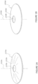
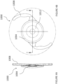
- Figure 1A illustrates a mask 2034a having an annular region 2036a surrounding an aperture 2038a substantially centrally located on the mask 2034a.
- An anterior surface of the annular region 2036a can have a curvature from the outer periphery to the inner periphery of the annular region 2036a, and the posterior surface of the annular region 2036a can have a similar curvature.
- the mask 2034b can also be flat.
- the mask 2034b can include an annular region 2036b surrounding an aperture 2038b substantially centered on the optical axis 2039b of the mask 2034b, Although the features described below are described with respect to the mask 2034a, one or the more of the features may be applied to the mask 2034b.
- the outer periphery of the mask 2034a is generally circular with an outer diameter of at least about 3 mm and less than about 6 mm. In some implementations, the diameter of the outer periphery of the mask 2034a is at least about 3 mm and less than or equal to about 4 mm.
- a thickness of the mask 2034a can be constant or can vary between the inner periphery (near the aperture) and the outer periphery. For example, the thickness may increase from an outer periphery and/or inner periphery of the mask 2034a and toward a radial midline of the annular region 2036a.
- the thickness at any location of the mask 2034a can be less than or equal to about 200 microns, or less than or equal to about 100 microns, but preferably between about 1 micron and about 20 microns.
- the thickness of the mask 2034a can be within the range: from about 1 micron to about 40 microns, from about 5 microns to about 20 microns, from about 5 microns to about 15 microns.
- the thickness of the mask 2034a can be within about two microns of: about 15 microns, about 10 microns, about 8 microns, or about 5 microns.
- the aperture 2038a can transmit substantially all incident visible light along the optical axis 2039a.
- the aperture 2038a can be a through-hole in the annular region 2036a or a substantially light transmissive (e.g., transparent to visible light) portion thereof.
- the aperture 2038a can be substantially circular and/or substantially centered around the optical axis 2039a of the mask 2034a.
- the size of the aperture 2038a can be any size that is effective to increase the depth of focus of an eye of a patient with presbyopia.
- the size of the aperture 2038a can be dependent on the location of the mask within the eye (e.g., distance from the retina).
- the aperture 2038a can have a diameter of at least about 0.85 mm and less than or equal to about 2.2 mm, at least about 1.1 mm and less than or equal to about 1.6 mm, or at least about 1.3 mm and less than or equal to about 1.4 mm.
- the annular region 2036a can prevent transmission of substantially all or at least a portion of the spectrum of the incident visible light (e.g., radiant energy in the electromagnetic spectrum that is visible to the human eye) and/or the spectrum of nonvisible light (e.g., radiant energy outside the range visible to humans). Preventing transmission of visible light through the annular region 2036a can block light that would not converge at the retina and fovea to form a sharp image.
- the annular region 2036a can prevent transmission of at least about: 90 percent of incident visible light, 92 percent of incident visible light, 95 percent of incident visible light, 98 percent of all incident visible light, or 99 percent of all incident visible light.
- the annular region 2036a can transmit no more than about: 10 percent of incident visible light, 8 percent of incident visible light, 5 percent of incident visible light, 3 percent of incident visible light, 2 percent of incident visible light, or 1 percent of incident visible light.
- opacity of the annular region 2036a is achieved because the material used to make mask 2034a is naturally opaque.
- the material used to make the mask 2034a may be naturally substantially clear but treated with a dye or other pigmentation agent (e.g., carbon black).
- the intraocular lens 1000 includes an optic 1004 and a mask 1012.
- the optic 1004 can be formed from an optically transmissive material, while the mask can be formed from an opaque material.
- the optic 1004 may be monofocal or multifocal and it can have positive or negative optical power.
- the optic 1004 may be aspheric or any other configuration as the context may dictate.
- the greatest thickness of the optic 1004 is at the center of the optic 1004.
- the optic 1004 may have a reduced thickness at its center, which is further described in U.S. Publication No. 2011/0040376, filed August 13, 2010 .
- the optic 1004 may be substantially circular with an outer diameter between about 5.0 mm and about 8.0 mm, such as about 6.0 mm.
- a central thickness of the optic 1004 can be less than or equal to about 1.0 mm, such as between about 0.75 mm and about 1.0 mm.
- the intraocular lens 1000 may include one or more haptics 1008 (e.g., one, two, three, four, or more) to prevent the intraocular lens 1000 from moving or rotating within the eye.
- haptics is intended to be a broad term encompassing struts and other mechanical structures that can be apposed against an inner surface of an eye and mounted to an optic to securely position an intraocular lens in an optical path of an eye.
- the haptics 1008 can be a variety of shapes and sizes depending on the location the intraocular lens 1000 is implanted in the eye.
- the haptics 1008 may be C-shaped, J-shaped, plate design, or any other design.
- the haptics 1008 may be manufactured substantially flat or vaulted with respect to the optic. Variations on the shape of the optic and the haptics can be found in U.S. Publication No. 2011/0040376, filed August 13, 2010 .
- the mask 1012 can be formed on an anterior surface 1016 of the optic 1004 (see Figures 2A-2D ), on a posterior surface 1020 of the optic 1004 (see Figures 3A-3D ), or embedded within the optic 1004 (see Figures 4A-4D ).
- the mask 1012 can be formed substantially at the midway line between the posterior 1020 and anterior surfaces 1016 of the optic 1004. But the mask 1012 can also be formed at other locations within the optic 1004.
- the optic 1004 can be formed by molding a liquid lens material, such as an acrylic or silicone material, and curing the material into a solid.
- a completed solid mask 1012 can be pre-manufactured (e.g., from a different material than the optic) and positioned on or in the optic as part of this molding process.
- the mask 1012 is pre-manufactured and then molded into the optic, there is a potential for an inadequate bond between the mask and the optic.
- the mask and the optic are made of different materials, there is a potential that the optical performance of the intraocular lens can be compromised due to the mask and optic materials potentially having elasticities and/or thermal expansion properties, which are too dissimilar.
- the material properties of the optic 1004 and the mask 1012 are not adequately compatible, then deformations, such as those resulting from injection forces during surgical implantation or swelling that may occur during manufacture due to chemical extractions, may damage the intraocular lens. Similarly, temperature shifts that occur during manufacture and/or surgical implantation can also damage the intraocular lens.
- the mask can be molded from the same material as the optic (e.g., a liquid acrylic or silicone material) at the same general time and/or such that the mask and optic undergo similar curing sequences (e.g., the mask and optic can be at least partially cured together).
- the mask can be formed from, a liquid material that has been modified to be substantially opaque by mixing in a dark pigment dye or dark particles, whereas the optic can be formed from the unmodified transparent liquid material.
- mixing, bleeding, and/or blending can occur between the opaque mask material and the transparent optic material. If this occurs, the outer and inner diameter borders of the mask can become blurred and/or diffuse. This can negatively impact the optical performance of the intraocular lens.
- This mixing, bleeding, and/or blending of the opaque and transparent liquid materials can be reduced or prevented by providing a mask-forming feature in the lens mold which can help prevent the opaque material from spreading beyond the desired region where the mask is to be formed on the surface of the optic or within the optic.
- the mask-forming feature comprises an annular trough formed in the lens mold at the location where the mask is to be positioned. This mask-forming trough can have inner and outer diameters, which correspond to the desired size of the mask.
- the opaque material used to form the mask is added to fill this trough.
- Transparent material used to form the optic is added over or around the opaque material in the mask-forming trough.
- the trough can help to prevent the opaque material from mixing, bleeding, and/or blending with the transparent material in a way that would blur the outer or inner diameter of the mask.
- the trough can achieve this, for example, through surface tension, which helps to hold the opaque material in place.
- more precise mask borders can be achieved.
- the inner border line of the mask (which defines the central circular aperture 2038) and the outer border line of the mask (which defines the outer circular perimeter of the mask 2034) can each be circular to within ⁇ 100 microns (e.g., any location along the inner or outer border of the mask can be within 100 microns of a perfect circle [or within 75 microns, or within 50 microns, or within 25 microns]).
- the outer border and the inner border can be concentric to within ⁇ 200 microns (e.g., the outer border and the inner border at any given angular position can be within 200 microns of being perfectly concentric [or within 150 microns, or within 100 microns, or within 50 microns]).
- a lens forming surface of the lens mold When forming an intraocular lens with the mask positioned on an anterior or posterior surface of the optic, a lens forming surface of the lens mold includes a mask-forming feature located at a position where the mask is to be formed.
- the mask-forming feature is generally annular and defined by an outer edge and an inner edge. These edges can be sharp knife edges in order to more effectively hold the opaque mask material in place via surface tension.
- the lens forming surface can also include an optic region positioned radially inward and/or outward of the mask-forming feature.
- the mask-forming feature comprises an annular trough. This trough can be etched, machined, or otherwise cut into the lens forming surface of the lens mold.
- the trough can have a minimum, depth that creates a mask thickness which provides less than 5% Sight transmission (or less than 3% or less than 2%).
- the depth of the trough can be at least about 4 microns, or between about 5 microns and about 10 microns. But the trough can be as deep as practically appropriate without causing dissimilar material property interactions between the mask material and the optic material, resulting in poor injection performance (e.g., a maximum trough depth of about 150 microns).
- the optic region of the lens forming surface of the mold will generally be curved in order to provide the intraocular lens with refractive optical power.
- the mask-forming feature can have a different radius of curvature than the optic region. This difference in radius of curvature can result in a trough in the lens forming surface to create the mask-forming feature and facilitate the creation of a precise border between the mask and the optic.
- the radius of curvature of the mask-forming feature can be between about 25% and about 50% of the radius of the optic region, such as between about 25% and 35%, between about 30% and about 40%, between about 35% and about 45%, between about 40% and about 50%, or otherwise.
- the radius of curvature of the mask-forming feature can be between about 30% and about 35% of the radius of the optic region, such as about 32%. In other implementations, however, the mask-forming feature and the optic region can have the same radius of curvature, but can be separated by a stepped transition.
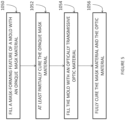
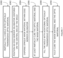
- Figure 5 is a flow chart illustrating a method of manufacturing an intraocular lens with a mask positioned on the anterior or posterior side of the optic.
- the method can include preparing a mixture of uncured mask material (e.g., an acrylic copolymer or silicone) mixed or impregnated with a high density of carbon black particles or other black dye or pigments as needed to provide opaque properties (e.g., to permit no more than about 2% light transmission).
- a specific and precise volume of uncured opaque mask material can be dispensed (e.g., with a cannula) to fill the mask-forming feature and define an outer diameter and an inner diameter of the mask (block 1050).
- the dispensed volume can be specifically controlled to conform to the outer and inner edges of the mask-forming feature of the mold.
- the exposed surface of the uncured mask material i.e., opposite the lens forming surface
- the mask material can have a viscosity and/or surface tension that can range from approximately that of water to acetic acid per as specified below: Fluid Absolute Viscosity Surface Tension (N s / m 2 , Pa s) (cp) (10 4 lb m / ft sec) mN / m Acetic acid 0.0011550 1.155 7.760 27.60 @ 20 C Water 0.0008900 0.890 6.000 71.95 @ 25 C
- the mask After filling the mask-forming feature, the mask can optionally be partially or fully cured using, for example, a combination of UV light and heat cycles (block 1052). Thereafter, the mold can be filled with an optically transmissive optic material, which may be the same as the mask material (e.g., acrylic or silicone), to over-mold the mask (block 1054). Finally, the mask material and the optic material can be fully cured-again, using a combination of UV light and heat cycles (block 1056).
- an optically transmissive optic material which may be the same as the mask material (e.g., acrylic or silicone)
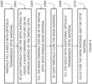
- the intraocular lens may be manufactured with the mask embedded within the optic.
- the method can include at least partially filling a first mold portion with an uncured optic material (block 1060).
- the first mold portion can be filled up to the depth where the mask is to be formed in the interior of the optic. In this way, the optic is initially only partially formed just to the thickness where the mask will be embedded in the completed optic.
- the first mold portion need not include a mask-forming feature.
- a second mold portion which mates with the first mold portion, can include a structure that is the physical complement of the desired mask-forming feature.
- the second mold portion can include an annular projection located where the mask is to be formed.
- the annular projection will form a trough in the partially-formed optic. As discussed further below, after at least partial curing of the optic material in the first mold portion, this trough in the partially-formed optic becomes the mask-forming feature and can be filled with opaque mask material.
- the uncured transparent optic material can be partially or fully cured to form a trough in the interior surface of the partial optic (block 1062).
- the trough in the partial optic can be filled with an opaque mask material (block 1064).
- the opaque mask material can be prepared, for example, by mixing or impregnating an optically transmissive mask material (e.g., an acrylic copolymer or silicone) with a high density of carbon black particles or other black dye or pigments as needed to provide opaque properties (e.g., to permit no more than about 2% light transmission).
- a specific and precise volume of uncured opaque mask material can be dispensed (e.g., with a cannula) to exactly fill the trough in the partial optic and define an outer diameter and an inner diameter of the annular mask.
- the dispensed volume can be specifically controlled to conform to the outer and inner edges of the trough in the partial optic.
- the exposed surface of the uncured mask material i.e., opposite interior surface of the optic
- the mask can optionally be partially or fully cured (block 1066). Thereafter, the mold can be filled with additional optic material to over-mold the mask (block 1068).
- a third mold portion can be used in place of the second mold portion to form an outer surface of the optic.
- the mask material and the optic material can be fully cured (block 1070).
- one of the mold portions may include a protruding pin that defines the inner diameter of the mask-forming feature and radially centers the mask in the optic.
- FIG. 7 and Figures 9A-9F An alternative method of manufacturing an intraocular lens with an embedded mask is illustrated in Figure 7 and Figures 9A-9F .
- This method does not form part of the invention.
- a measured partial volume of liquid type uncured optic material 2060 can be placed in a mold half 2062a (block 1080 and Figure 9A ).
- An edge border delineator 2050 can be placed on the center of the liquid optic material 2060 (block 1082 and Figure 9B ).
- a bead of opaque mask material 2064 can be dispensed within the lines of the edge border delineator 2050 (block 1084). The opaque mask material 2064 wicks to the confinements of the edge border delineator 2050 ( Figure 9C ).
- a bead of uncured optic material 2060 can be dispensed within the central aperture of the edge border delineator 2050 ( Figure 9D ).
- the bead of optic material 2060 wicks to the inner periphery of the edge border delineator. At least the surface of the optic material 2060 can be partially cured at this time (block 1086).
- a measured partial volume of uncured optic material 2060 can be placed into the opposite mold half 2062b (block 1088).
- the two mold halves 2062a, 2062b can then be joined together and the intraocular lens can be put through the full curing process (block 1090 and Figure 9E ). Thereafter, the intraocular lens can be removed from the mold ( Figure 9F ).
- FIG. 8A illustrates an embodiment of the edge border delineator 2050.
- the edge border delineator 2050 can include an outer border 2052 spaced apart from an inner border 2054.
- the opaque mask material can be dispensed between the outer border 2052 and the inner border 2054.
- the bead of optic material can be dispensed radially inward of the inner border 2054.
- the edge border delineator 2050 can be made from compatible polymer or elastic type polymer material (e.g., an acrylic copolymer or silicone).
- a width of the inner and/or outer border 2054, 2052 (e.g., in a radial direction) can be within a range of 100 microns to 500 microns.
- the thickness of the inner and/or outer border 2054, 2052 (e.g., in an anterior-posterior direction) can be between about 5 and 15 microns thick with a flat formed shape.
- Connecting spokes 2056 may or may not be used to maintain inner and outer border concentricity (see Figure 8B ).
- the cross-sectional profile of the inner and/or outer border 2054, 2052 can be vertical, stair stepped (see Figure 8C ), sloped (see Figure 8D ), fully contained (see Figure 8E ), or any other profile to facilitate the wicking/capillary action of the liquid acrylic as necessary.
- a plurality of mechanical locking holes can be provided in the edge border delineator to support capillary action and to minimize delamination of the intraocular during injection.
Landscapes
- Health & Medical Sciences (AREA)
- Engineering & Computer Science (AREA)
- Ophthalmology & Optometry (AREA)
- Vascular Medicine (AREA)
- Animal Behavior & Ethology (AREA)
- Oral & Maxillofacial Surgery (AREA)
- Biomedical Technology (AREA)
- Heart & Thoracic Surgery (AREA)
- Cardiology (AREA)
- Life Sciences & Earth Sciences (AREA)
- Transplantation (AREA)
- General Health & Medical Sciences (AREA)
- Public Health (AREA)
- Veterinary Medicine (AREA)
- Manufacturing & Machinery (AREA)
- Mechanical Engineering (AREA)
- Prostheses (AREA)
Description
- This application relates generally to the field of intraocular devices. More particularly, this application is directed to methods of manufacturing intraocular lenses (IOLs) with an aperture to increase depth of focus (e.g., "masked" intraocular lenses).
- The human eye functions to provide vision by transmitting and focusing light through a clear outer portion called the cornea, and further refining the focus of the image onto a retina by way of a crystalline lens. The quality of the focused image depends on many factors including the size and shape of the eye, and the transparency of the cornea and the lens.
- The optical power of the eye is determined by the optical power of the cornea and the crystalline lens. In a normal, healthy eye, sharp images of distant objects are formed on the retina (emmetropia). In many eyes, images of distant objects are either formed in front of the retina because the eye is abnormally long or the cornea is abnormally steep (myopia), or formed in back of the retina because the eye is abnormally short or the cornea is abnormally flat (hyperopia). The cornea also may be asymmetric or toric, resulting in an uncompensated cylindrical refractive error referred to as corneal astigmatism.
- Some people suffer from cataracts in which the crystalline lens undergoes a loss of transparency. In such cases, the crystalline lens can be removed and replaced with an intraocular lens (IOL). However, some intraocular lenses may still leave defects in a patient's non-distance eyesight.
- In
US 2012/310338 there are described intraocular implants and methods of making intraocular implants. The intraocular implants can improve the vision of a patient, such as by increasing the depth of focus of an eye of a patient. In particular, the intraocular implants include a mask having an annular portion with a relatively low visible light transmission surrounding a relatively high transmission central portion such as a clear lens or aperture. This construct is adapted to provide an annular mask with a small aperture for light to pass through to the retina to increase depth of focus. The intraocular implant may have an optical power for refractive correction. The intraocular implant may be implanted in any location along the optical pathway in the eye, e.g., as an implant in the anterior or posterior chamber. - In
US 2014/131905 there are described Intraocular implants and methods of making intraocular implants. The intraocular implant includes a mask adapted to increase depth of focus. The method of making the intraocular implant includes suspending the mask along an optical axis of the intraocular implant using a centration tool. - Methods of manufacturing masked intraocular lenses can include a molding process. In general, the molding process can include pouring an uncured material into a mold and then curing the material with a combination of UV light and heat temperature cycles. However, when performing a molding process with both optically transmissive and opaque materials (e.g., an optically transmissive optic material and an opaque mask material), it can be difficult to produce precise border lines between the optic and the aperture, which can reduce the optical performance of the intraocular lens.
- The present disclosure is generally related to methods of manufacturing a masked intraocular lens with an annular mask embedded within or positioned on an anterior or a posterior surface of the optic. The mask and the optic may comprise the same material, such as an acrylic copolymer or silicone. The methods disclosed herein produce a precise border line at the interface between inner and outer diameters of the mask and the optic.
- According to the present invention there is provided a method in accordance with claim 1. Further embodiments are set out in the dependent claims.
- Various examples are depicted in the accompanying drawings for illustrative purposes, and should in no way be interpreted as limiting the scope of the invention. Furthermore, various features of different disclosed examples can be combined to form additional examples, which are part of this disclosure.
-
Figure 1A illustrates an example of a mask. -
Figure 1B illustrates another example of a mask. -
Figures 2A-2D illustrate an example of an intraocular lens having a mask positioned on an anterior surface of the optic. -
Figures 3A-3D illustrate another example of an intraocular lens having a mask positioned on a posterior surface of the optic. -
Figures 4A-4D illustrate yet another example of an intraocular lens having a mask embedded in the optic. -
Figure 5 is a flow chart of a method of manufacturing an intraocular lens with a mask positioned on a surface of the optic. -
Figure 6 is a flow chart of a method of manufacturing an intraocular lens with a mask embedded in the optic. -
Figure 7 is a flow chart of another method of manufacturing an intraocular lens within a mask embedded in the optic. -
Figures 8A-8E illustrate different examples of a mold delineator. -
Figures 9A-9F illustrate a method of manufacturing an intraocular lens using the steps shown inFigure 7 . - Patients who undergo intraocular lens (IOL) implantation surgery may still suffer from defects in their non-distance eyesight (e.g., presbyopia). One technique for treating such defects is by including an annular mask within or on the optic that increases the patient's depth of focus. The light rays that pass through the aperture in the mask converge at a focal point on the retina, while the light rays that would not converge at the focal point on the retina are blocked by an opaque portion of the mask configured to prevent at least some or substantially all visible light from being transmitted through the mask.
-
Figure 1A illustrates a mask 2034a having an annular region 2036a surrounding an aperture 2038a substantially centrally located on the mask 2034a. An anterior surface of the annular region 2036a can have a curvature from the outer periphery to the inner periphery of the annular region 2036a, and the posterior surface of the annular region 2036a can have a similar curvature. However, as shown inFigure 1B , the mask 2034b can also be flat. The mask 2034b can include an annular region 2036b surrounding an aperture 2038b substantially centered on the optical axis 2039b of the mask 2034b, Although the features described below are described with respect to the mask 2034a, one or the more of the features may be applied to the mask 2034b. - In some implementations, the outer periphery of the mask 2034a is generally circular with an outer diameter of at least about 3 mm and less than about 6 mm. In some implementations, the diameter of the outer periphery of the mask 2034a is at least about 3 mm and less than or equal to about 4 mm.
- A thickness of the mask 2034a can be constant or can vary between the inner periphery (near the aperture) and the outer periphery. For example, the thickness may increase from an outer periphery and/or inner periphery of the mask 2034a and toward a radial midline of the annular region 2036a. In general, the thickness at any location of the mask 2034a can be less than or equal to about 200 microns, or less than or equal to about 100 microns, but preferably between about 1 micron and about 20 microns. For example, the thickness of the mask 2034a can be within the range: from about 1 micron to about 40 microns, from about 5 microns to about 20 microns, from about 5 microns to about 15 microns. In some implementations, the thickness of the mask 2034a can be within about two microns of: about 15 microns, about 10 microns, about 8 microns, or about 5 microns.
- The aperture 2038a can transmit substantially all incident visible light along the optical axis 2039a. For example, the aperture 2038a can be a through-hole in the annular region 2036a or a substantially light transmissive (e.g., transparent to visible light) portion thereof. The aperture 2038a can be substantially circular and/or substantially centered around the optical axis 2039a of the mask 2034a. The size of the aperture 2038a can be any size that is effective to increase the depth of focus of an eye of a patient with presbyopia. In particular, the size of the aperture 2038a can be dependent on the location of the mask within the eye (e.g., distance from the retina). In some implementations, the aperture 2038a can have a diameter of at least about 0.85 mm and less than or equal to about 2.2 mm, at least about 1.1 mm and less than or equal to about 1.6 mm, or at least about 1.3 mm and less than or equal to about 1.4 mm.
- The annular region 2036a can prevent transmission of substantially all or at least a portion of the spectrum of the incident visible light (e.g., radiant energy in the electromagnetic spectrum that is visible to the human eye) and/or the spectrum of nonvisible light (e.g., radiant energy outside the range visible to humans). Preventing transmission of visible light through the annular region 2036a can block light that would not converge at the retina and fovea to form a sharp image. In some implementations, the annular region 2036a can prevent transmission of at least about: 90 percent of incident visible light, 92 percent of incident visible light, 95 percent of incident visible light, 98 percent of all incident visible light, or 99 percent of all incident visible light. In other words, the annular region 2036a can transmit no more than about: 10 percent of incident visible light, 8 percent of incident visible light, 5 percent of incident visible light, 3 percent of incident visible light, 2 percent of incident visible light, or 1 percent of incident visible light.
- In some implementations, opacity of the annular region 2036a is achieved because the material used to make mask 2034a is naturally opaque. In other implementations, the material used to make the mask 2034a may be naturally substantially clear but treated with a dye or other pigmentation agent (e.g., carbon black).
- Further variations of masks can be found in
U.S. Patent No. 7,628,810, filed May 26, 2004 ,U.S. Publication No. 2012/0143325, filed February 19, 2012 ,U.S. Publication No. 2011/0040376, filed August 13, 2010 ;U.S. Publication No. 2013/0268071, filed November 30, 2012 ;U.S. Publication No. 2014/0264981 ;U.S. Publication No. 2015/0073549, filed August 7, 2014 ;U.S. Patent No. 5,662,706, filed June 14, 1996 ;U.S. Patent No. 5,905,561, filed June 14, 1996 ; andU.S. Patent No. 5,965,330, filed December 6, 1996 . - As shown in
Figures 2A-2D , theintraocular lens 1000 includes an optic 1004 and amask 1012. The optic 1004 can be formed from an optically transmissive material, while the mask can be formed from an opaque material. - The optic 1004 may be monofocal or multifocal and it can have positive or negative optical power. The optic 1004 may be aspheric or any other configuration as the context may dictate. In some implementations, the greatest thickness of the optic 1004 is at the center of the
optic 1004. In other implementations, the optic 1004 may have a reduced thickness at its center, which is further described inU.S. Publication No. 2011/0040376, filed August 13, 2010 . The optic 1004 may be substantially circular with an outer diameter between about 5.0 mm and about 8.0 mm, such as about 6.0 mm. A central thickness of the optic 1004 can be less than or equal to about 1.0 mm, such as between about 0.75 mm and about 1.0 mm. - The
intraocular lens 1000 may include one or more haptics 1008 (e.g., one, two, three, four, or more) to prevent theintraocular lens 1000 from moving or rotating within the eye. As used herein the term "haptic" is intended to be a broad term encompassing struts and other mechanical structures that can be apposed against an inner surface of an eye and mounted to an optic to securely position an intraocular lens in an optical path of an eye. Thehaptics 1008 can be a variety of shapes and sizes depending on the location theintraocular lens 1000 is implanted in the eye. Thehaptics 1008 may be C-shaped, J-shaped, plate design, or any other design. Thehaptics 1008 may be manufactured substantially flat or vaulted with respect to the optic. Variations on the shape of the optic and the haptics can be found inU.S. Publication No. 2011/0040376, filed August 13, 2010 . - The
mask 1012 can be formed on ananterior surface 1016 of the optic 1004 (seeFigures 2A-2D ), on aposterior surface 1020 of the optic 1004 (seeFigures 3A-3D ), or embedded within the optic 1004 (seeFigures 4A-4D ). When themask 1012 is embedded within theoptic 1004, themask 1012 can be formed substantially at the midway line between the posterior 1020 andanterior surfaces 1016 of theoptic 1004. But themask 1012 can also be formed at other locations within theoptic 1004. - In some implementations, the optic 1004 can be formed by molding a liquid lens material, such as an acrylic or silicone material, and curing the material into a solid. A completed
solid mask 1012 can be pre-manufactured (e.g., from a different material than the optic) and positioned on or in the optic as part of this molding process. However, in this type of process where themask 1012 is pre-manufactured and then molded into the optic, there is a potential for an inadequate bond between the mask and the optic. In addition, if the mask and the optic are made of different materials, there is a potential that the optical performance of the intraocular lens can be compromised due to the mask and optic materials potentially having elasticities and/or thermal expansion properties, which are too dissimilar. For example, if the material properties of the optic 1004 and themask 1012 are not adequately compatible, then deformations, such as those resulting from injection forces during surgical implantation or swelling that may occur during manufacture due to chemical extractions, may damage the intraocular lens. Similarly, temperature shifts that occur during manufacture and/or surgical implantation can also damage the intraocular lens. - It can therefore be advantageous to manufacture the intraocular lens using a process where the mask is molded from the same material as the optic (e.g., a liquid acrylic or silicone material) at the same general time and/or such that the mask and optic undergo similar curing sequences (e.g., the mask and optic can be at least partially cured together). For example, the mask can be formed from, a liquid material that has been modified to be substantially opaque by mixing in a dark pigment dye or dark particles, whereas the optic can be formed from the unmodified transparent liquid material. In this type of manufacturing process, however, mixing, bleeding, and/or blending can occur between the opaque mask material and the transparent optic material. If this occurs, the outer and inner diameter borders of the mask can become blurred and/or diffuse. This can negatively impact the optical performance of the intraocular lens.
- This mixing, bleeding, and/or blending of the opaque and transparent liquid materials can be reduced or prevented by providing a mask-forming feature in the lens mold which can help prevent the opaque material from spreading beyond the desired region where the mask is to be formed on the surface of the optic or within the optic. The mask-forming feature comprises an annular trough formed in the lens mold at the location where the mask is to be positioned. This mask-forming trough can have inner and outer diameters, which correspond to the desired size of the mask. The opaque material used to form the mask is added to fill this trough. Transparent material used to form the optic is added over or around the opaque material in the mask-forming trough. The trough can help to prevent the opaque material from mixing, bleeding, and/or blending with the transparent material in a way that would blur the outer or inner diameter of the mask. The trough can achieve this, for example, through surface tension, which helps to hold the opaque material in place. In this way, more precise mask borders can be achieved. For example, the inner border line of the mask (which defines the central circular aperture 2038) and the outer border line of the mask (which defines the outer circular perimeter of the mask 2034) can each be circular to within ± 100 microns (e.g., any location along the inner or outer border of the mask can be within 100 microns of a perfect circle [or within 75 microns, or within 50 microns, or within 25 microns]). In addition, the outer border and the inner border can be concentric to within ± 200 microns (e.g., the outer border and the inner border at any given angular position can be within 200 microns of being perfectly concentric [or within 150 microns, or within 100 microns, or within 50 microns]).
- When forming an intraocular lens with the mask positioned on an anterior or posterior surface of the optic, a lens forming surface of the lens mold includes a mask-forming feature located at a position where the mask is to be formed. The mask-forming feature is generally annular and defined by an outer edge and an inner edge. These edges can be sharp knife edges in order to more effectively hold the opaque mask material in place via surface tension. The lens forming surface can also include an optic region positioned radially inward and/or outward of the mask-forming feature. As just mentioned, the mask-forming feature comprises an annular trough. This trough can be etched, machined, or otherwise cut into the lens forming surface of the lens mold. The trough can have a minimum, depth that creates a mask thickness which provides less than 5% Sight transmission (or less than 3% or less than 2%). In some implementations, the depth of the trough can be at least about 4 microns, or between about 5 microns and about 10 microns. But the trough can be as deep as practically appropriate without causing dissimilar material property interactions between the mask material and the optic material, resulting in poor injection performance (e.g., a maximum trough depth of about 150 microns).
- The optic region of the lens forming surface of the mold will generally be curved in order to provide the intraocular lens with refractive optical power. In such arrangements, the mask-forming feature can have a different radius of curvature than the optic region. This difference in radius of curvature can result in a trough in the lens forming surface to create the mask-forming feature and facilitate the creation of a precise border between the mask and the optic. The radius of curvature of the mask-forming feature can be between about 25% and about 50% of the radius of the optic region, such as between about 25% and 35%, between about 30% and about 40%, between about 35% and about 45%, between about 40% and about 50%, or otherwise. In some implementations, the radius of curvature of the mask-forming feature can be between about 30% and about 35% of the radius of the optic region, such as about 32%. In other implementations, however, the mask-forming feature and the optic region can have the same radius of curvature, but can be separated by a stepped transition.
-
Figure 5 is a flow chart illustrating a method of manufacturing an intraocular lens with a mask positioned on the anterior or posterior side of the optic. The method can include preparing a mixture of uncured mask material (e.g., an acrylic copolymer or silicone) mixed or impregnated with a high density of carbon black particles or other black dye or pigments as needed to provide opaque properties (e.g., to permit no more than about 2% light transmission). A specific and precise volume of uncured opaque mask material can be dispensed (e.g., with a cannula) to fill the mask-forming feature and define an outer diameter and an inner diameter of the mask (block 1050). By relying on surface tension and capillary action of the viscous mask material, the dispensed volume can be specifically controlled to conform to the outer and inner edges of the mask-forming feature of the mold. The exposed surface of the uncured mask material (i.e., opposite the lens forming surface) can exhibit a curvature. To achieve these results, the mask material can have a viscosity and/or surface tension that can range from approximately that of water to acetic acid per as specified below:Fluid Absolute Viscosity Surface Tension (N s/m2, Pa s) (cp) (104 lbm /ft sec) mN/m Acetic acid 0.0011550 1.155 7.760 27.60 @ 20 C Water 0.0008900 0.890 6.000 71.95 @ 25 C - After filling the mask-forming feature, the mask can optionally be partially or fully cured using, for example, a combination of UV light and heat cycles (block 1052). Thereafter, the mold can be filled with an optically transmissive optic material, which may be the same as the mask material (e.g., acrylic or silicone), to over-mold the mask (block 1054). Finally, the mask material and the optic material can be fully cured-again, using a combination of UV light and heat cycles (block 1056).
- In an alternative arrangement that does not form part of the invention, the intraocular lens may be manufactured with the mask embedded within the optic. The method can include at least partially filling a first mold portion with an uncured optic material (block 1060). The first mold portion can be filled up to the depth where the mask is to be formed in the interior of the optic. In this way, the optic is initially only partially formed just to the thickness where the mask will be embedded in the completed optic. In this case, the first mold portion need not include a mask-forming feature. Instead, a second mold portion, which mates with the first mold portion, can include a structure that is the physical complement of the desired mask-forming feature. For example, the second mold portion can include an annular projection located where the mask is to be formed. The annular projection will form a trough in the partially-formed optic. As discussed further below, after at least partial curing of the optic material in the first mold portion, this trough in the partially-formed optic becomes the mask-forming feature and can be filled with opaque mask material.
- After the first and second mold portions are mated together, the uncured transparent optic material can be partially or fully cured to form a trough in the interior surface of the partial optic (block 1062). The trough in the partial optic can be filled with an opaque mask material (block 1064). The opaque mask material can be prepared, for example, by mixing or impregnating an optically transmissive mask material (e.g., an acrylic copolymer or silicone) with a high density of carbon black particles or other black dye or pigments as needed to provide opaque properties (e.g., to permit no more than about 2% light transmission). A specific and precise volume of uncured opaque mask material can be dispensed (e.g., with a cannula) to exactly fill the trough in the partial optic and define an outer diameter and an inner diameter of the annular mask. By relying on surface tension and capillary action of the viscous mask material, the dispensed volume can be specifically controlled to conform to the outer and inner edges of the trough in the partial optic. The exposed surface of the uncured mask material (i.e., opposite interior surface of the optic) can exhibit a curvature. After filling the trough in the partial optic, the mask can optionally be partially or fully cured (block 1066). Thereafter, the mold can be filled with additional optic material to over-mold the mask (block 1068). A third mold portion can be used in place of the second mold portion to form an outer surface of the optic. Finally, the mask material and the optic material can be fully cured (block 1070). In some implementations, one of the mold portions may include a protruding pin that defines the inner diameter of the mask-forming feature and radially centers the mask in the optic.
- An alternative method of manufacturing an intraocular lens with an embedded mask is illustrated in
Figure 7 andFigures 9A-9F . This method does not form part of the invention. A measured partial volume of liquid typeuncured optic material 2060 can be placed in amold half 2062a (block 1080 andFigure 9A ). Anedge border delineator 2050 can be placed on the center of the liquid optic material 2060 (block 1082 andFigure 9B ). A bead ofopaque mask material 2064 can be dispensed within the lines of the edge border delineator 2050 (block 1084). Theopaque mask material 2064 wicks to the confinements of the edge border delineator 2050 (Figure 9C ). Optionally, a bead ofuncured optic material 2060 can be dispensed within the central aperture of the edge border delineator 2050 (Figure 9D ). The bead ofoptic material 2060 wicks to the inner periphery of the edge border delineator. At least the surface of theoptic material 2060 can be partially cured at this time (block 1086). A measured partial volume ofuncured optic material 2060 can be placed into theopposite mold half 2062b (block 1088). The twomold halves Figure 9E ). Thereafter, the intraocular lens can be removed from the mold (Figure 9F ). -
Figures 8A illustrates an embodiment of theedge border delineator 2050. Theedge border delineator 2050 can include anouter border 2052 spaced apart from aninner border 2054. As explained above, the opaque mask material can be dispensed between theouter border 2052 and theinner border 2054. The bead of optic material can be dispensed radially inward of theinner border 2054. Theedge border delineator 2050 can be made from compatible polymer or elastic type polymer material (e.g., an acrylic copolymer or silicone). A width of the inner and/orouter border 2054, 2052 (e.g., in a radial direction) can be within a range of 100 microns to 500 microns. The thickness of the inner and/orouter border 2054, 2052 (e.g., in an anterior-posterior direction) can be between about 5 and 15 microns thick with a flat formed shape. Connectingspokes 2056 may or may not be used to maintain inner and outer border concentricity (seeFigure 8B ). The cross-sectional profile of the inner and/orouter border Figure 8C ), sloped (seeFigure 8D ), fully contained (seeFigure 8E ), or any other profile to facilitate the wicking/capillary action of the liquid acrylic as necessary. A plurality of mechanical locking holes can be provided in the edge border delineator to support capillary action and to minimize delamination of the intraocular during injection. - Conditional language, such as "can," "could," "might," or "may," unless specifically stated otherwise, or otherwise understood within the context as used, is generally intended to convey that certain embodiments include, while other embodiments do not include, certain features, elements, and/or steps. Thus, such conditional language is not generally intended to imply that features, elements, and/or steps are in any way required for one or more embodiments or that one or more embodiments necessarily include logic for deciding, with or without user input or prompting, whether these features, elements, and/or steps are included or are to be performed in any particular embodiment.
- The terms "comprising," "including," "having," and the like are synonymous and are used inclusively, in an open-ended fashion, and do not exclude additional elements, features, acts, operations, and so forth. Also, the term "or" is used in its inclusive sense (and not in its exclusive sense) so that when used, for example, to connect a list of elements, the term "or" means one, some, or all of the elements in the list.
- The terms "approximately," "about," and "substantially" as used herein represent an amount close to the stated amount that still performs a desired function or achieves a desired result. For example, the terms "approximately," "about," and "substantially" may refer to an amount that is within less than 10% of the stated amount, as the context may dictate.
- The ranges disclosed herein also encompass any and all overlap, subranges, and combinations thereof. Language such as "up to," "at least," "greater than," "less than," "between" and the like includes the number recited. Numbers preceded by a term such as "about" or "approximately" include the recited numbers. For example, "about 3 mm" includes "3 mm."
- Although certain embodiments and examples have been described herein, it will be understood by those skilled in the art that many aspects of the methods and IOLs shown and described in the present disclosure may be differently combined and/or modified to form still further embodiments or acceptable examples. All such modifications and variations are intended to be included herein within the scope of this disclosure. A wide variety of designs and approaches are possible. No feature, structure, or step disclosed herein is essential or indispensable.
- For purposes of this disclosure, certain aspects, advantages, and novel features are described herein. It is to be understood that not necessarily all such advantages may be achieved in accordance with any particular embodiment. Thus, for example, those skilled in the art will recognize that the disclosure may be embodied or carried out in a manner that achieves one advantage or a group of advantages as taught herein without necessarily achieving other advantages as may be taught or suggested herein.
- Moreover, while illustrative embodiments have been described herein, the scope of any and all embodiments having equivalent elements, modifications, omissions, combinations (e.g., of aspects across various embodiments), adaptations and/or alterations as would be appreciated by those in the art based on the present disclosure. The limitations in the claims are to be interpreted broadly based on the language employed in the claims and not limited to the examples described in the present specification or during the prosecution of the application, which examples are to be construed as non-exclusive. Further, the actions of the disclosed processes and methods may be modified in any manner, including by reordering actions and/or inserting additional actions and/or deleting actions. It is intended, therefore, that the specification and examples be considered as illustrative only, with a true scope being indicated by the claims.
Claims (15)
- A method of manufacturing an intraocular lens, the method comprising:filling an annular mask-forming feature in a lens mold with an opaque mask material (1050), the annular mask-forming feature comprising a trough provided in a portion of the lens mold;adding optically transmissive optic material over the opaque mask material (1054); and,fully curing the opaque mask material and the optically transmissive optic material to form a mask and an optic (1056), the mask being sufficient to prevent transmission of at least 90% of incident visible light.
- The method of Claim 1, further comprising preparing the opaque mask material by mixing an optically transmissive material with an opaque agent.
- The method of Claim 2, wherein the optically transmissive material comprises acrylic.
- The method of Claim 2, wherein the opaque agent comprises carbon black.
- The method of any one of Claims 1 to 4, further comprising at least partially curing the opaque mask material (1052) before adding the optically transmissive optic material over the opaque mask material.
- The method of Claim 5, wherein at least partially curing the opaque mask material comprises fully curing the opaque mask material.
- The method of Claim 1, wherein the mask is sufficient to prevent transmission of at least about 98% of incident visible light.
- The method of any one of Claims 1 to 7, wherein the opaque mask material and the optically transmissive optic material comprise the same material.
- The method of Claim 8, wherein the same material comprises acrylic.
- The method of any one of Claims 1 to 9, wherein a surface of the annular mask-forming feature has a radius of curvature that is about 25% to about 50% of a radius of curvature of the optic.
- The method of Claim 10, wherein the radius of curvature of the surface of the annular mask-forming feature is between about 30% and about 35% of the radius of curvature of the optic.
- The method of any of Claims 1 to 11, wherein the optic is monofocal
- The method of any of Claims 1 to 12, wherein the annular mask-forming feature has inner and outer diameters corresponding to a desired size of the mask.
- The method of any of Claims 1 to 13, wherein the trough is etched, machined, or cut into a lens forming surface of the lens mold.
- An intraocular lens formed by the method of any one of Claims 1 to 14.
Applications Claiming Priority (2)
| Application Number | Priority Date | Filing Date | Title |
|---|---|---|---|
| US201562237429P | 2015-10-05 | 2015-10-05 | |
| PCT/US2016/055207 WO2017062316A1 (en) | 2015-10-05 | 2016-10-03 | Methods of molding intraocular lenses |
Publications (3)
| Publication Number | Publication Date |
|---|---|
| EP3359987A1 EP3359987A1 (en) | 2018-08-15 |
| EP3359987A4 EP3359987A4 (en) | 2019-07-24 |
| EP3359987B1 true EP3359987B1 (en) | 2024-02-28 |
Family
ID=58488390
Family Applications (1)
| Application Number | Title | Priority Date | Filing Date |
|---|---|---|---|
| EP16854144.9A Active EP3359987B1 (en) | 2015-10-05 | 2016-10-03 | Methods of molding intraocular lenses |
Country Status (3)
| Country | Link |
|---|---|
| US (2) | US10687935B2 (en) |
| EP (1) | EP3359987B1 (en) |
| WO (1) | WO2017062316A1 (en) |
Families Citing this family (12)
| Publication number | Priority date | Publication date | Assignee | Title |
|---|---|---|---|---|
| US7628810B2 (en) | 2003-05-28 | 2009-12-08 | Acufocus, Inc. | Mask configured to maintain nutrient transport without producing visible diffraction patterns |
| US10004593B2 (en) | 2009-08-13 | 2018-06-26 | Acufocus, Inc. | Intraocular lens with elastic mask |
| JP5607163B2 (en) | 2009-08-13 | 2014-10-15 | アキュフォーカス・インコーポレーテッド | Intraocular implant and lens with mask |
| EP2785296B1 (en) | 2011-12-02 | 2018-06-20 | AcuFocus, Inc. | Ocular mask having selective spectral transmission |
| US9427922B2 (en) | 2013-03-14 | 2016-08-30 | Acufocus, Inc. | Process for manufacturing an intraocular lens with an embedded mask |
| US9943403B2 (en) | 2014-11-19 | 2018-04-17 | Acufocus, Inc. | Fracturable mask for treating presbyopia |
| US11547554B2 (en) | 2015-04-14 | 2023-01-10 | Z Optics, Inc. | High definition and extended depth of field intraocular lens |
| US11696823B2 (en) | 2015-04-14 | 2023-07-11 | Z Optics, Inc. | High definition and extended depth of field intraocular lens |
| EP3359987B1 (en) | 2015-10-05 | 2024-02-28 | AcuFocus, Inc. | Methods of molding intraocular lenses |
| WO2017091520A1 (en) | 2015-11-24 | 2017-06-01 | Acufocus, Inc. | Toric small aperture intraocular lens with extended depth of focus |
| CN107212949B (en) * | 2017-07-12 | 2019-05-14 | 无锡蕾明视康科技有限公司 | A kind of multifocal intraocular lenses |
| WO2019217471A1 (en) | 2018-05-09 | 2019-11-14 | Acufocus, Inc. | Intraocular implant with removable optic |
Family Cites Families (430)
| Publication number | Priority date | Publication date | Assignee | Title |
|---|---|---|---|---|
| US2350421A (en) | 1941-01-22 | 1944-06-06 | William P Schoder | Method of producing inlaid jewels |
| US2470927A (en) | 1947-01-10 | 1949-05-24 | South Chester Corp | Fastening means |
| US3034403A (en) | 1959-04-03 | 1962-05-15 | Neefe Hamilton Res Company | Contact lens of apparent variable light absorption |
| US3458870A (en) | 1964-05-25 | 1969-08-05 | William Stone Jr | Artificial corneal implants having a removable lens member |
| US3270099A (en) | 1964-12-07 | 1966-08-30 | Richard N Camp | A method for making multi-focal length contact lenses |
| GB1276003A (en) | 1969-03-10 | 1972-06-01 | Frank Auld | Corneal contact device |
| US3578850A (en) | 1970-02-11 | 1971-05-18 | Alan H Grant | Anti-flare contact lens |
| US3794414A (en) | 1972-05-12 | 1974-02-26 | Jessen Inc Wesley | Multiple focal contact lens |
| US3776230A (en) | 1973-04-18 | 1973-12-04 | C Neefe | Method of rapidly reshaping the cornea to eliminate refractive errors |
| US3877502A (en) | 1973-08-29 | 1975-04-15 | Hunckler Products Inc | Nut locking means and method for muffler clamps |
| US3996627A (en) | 1975-09-22 | 1976-12-14 | American Optical Corporation | Artificial intraocular lens |
| US4010496A (en) | 1975-10-01 | 1977-03-08 | Neefe Charles W | Bifocal lens which positions within the anterior chamber |
| US4104338A (en) | 1976-04-30 | 1978-08-01 | Guerrieri Salvatore A | Bubble cap tray |
| US4116439A (en) | 1976-09-30 | 1978-09-26 | C.F.F. Inc. | Pool ball |
| DE2727410C3 (en) | 1977-06-18 | 1980-03-06 | Friedrichsfeld Gmbh Steinzeug- Und Kunststoffwerke, 6800 Mannheim | Keratoprosthesis |
| US4210391A (en) | 1977-09-14 | 1980-07-01 | Cohen Allen L | Multifocal zone plate |
| US4340283A (en) | 1978-12-18 | 1982-07-20 | Cohen Allen L | Phase shift multifocal zone plate |
| US4767647A (en) | 1979-12-17 | 1988-08-30 | The D. L. Auld Company | Decorative emblem |
| US4435050A (en) | 1980-02-26 | 1984-03-06 | Stanley Poler | Contact lens assembly with haptic and method for making the same |
| US4298996A (en) | 1980-07-23 | 1981-11-10 | Barnet Ronald W | Magnetic retention system for intraocular lens |
| EP0046338B1 (en) | 1980-08-05 | 1985-04-10 | David Peter Choyce | Intraocular lens |
| US4450593A (en) | 1981-11-09 | 1984-05-29 | Lynell Medical Technology Inc. | Intraocular and contact lens construction |
| US4402579A (en) | 1981-07-29 | 1983-09-06 | Lynell Medical Technology Inc. | Contact-lens construction |
| SU1380743A1 (en) | 1982-02-15 | 1988-03-15 | Московский научно-исследовательский институт микрохирургии глаза | Artificial eye lens |
| US4423728A (en) | 1982-02-26 | 1984-01-03 | Lieberman David M | Cam-guided trephine |
| US4470159A (en) | 1982-03-03 | 1984-09-11 | Peyman Gholam A | Keratoprosthesis |
| US4639105A (en) | 1982-09-13 | 1987-01-27 | Neefe Charles W | Spin cast ocular cosmetic device with color separation |
| JPS5954527A (en) | 1982-09-22 | 1984-03-29 | Hashimoto Forming Co Ltd | Production of molding for vehicle |
| US4505855A (en) | 1982-09-30 | 1985-03-19 | Massachusetts General Hospital | Transparent non-fibrilized collagen material by ultracentrifugation |
| US4701038A (en) | 1983-01-31 | 1987-10-20 | Bausch & Lomb Incorporated | Cosmetic contact lens |
| US4563565A (en) | 1983-03-02 | 1986-01-07 | Minnesota Mining And Manufacturing Company | Method for forming a peripheral edge on contact lenses |
| US4512039A (en) | 1983-05-24 | 1985-04-23 | Lieberman David M | Method of offsetting postoperative astigmatism with an intraocular lens |
| DE3332313A1 (en) | 1983-09-07 | 1985-04-04 | Titmus Eurocon Kontaktlinsen GmbH, 8750 Aschaffenburg | MULTIFOCAL, ESPECIALLY BIFOCAL, INTRAOCULAR ARTIFICIAL EYE LENS |
| US4665913A (en) | 1983-11-17 | 1987-05-19 | Lri L.P. | Method for ophthalmological surgery |
| US4596578A (en) | 1984-01-30 | 1986-06-24 | Kelman Charles D | Intraocular lens with miniature optic |
| US5041133A (en) | 1984-04-11 | 1991-08-20 | Pharmacia Ab | Intraocular implant |
| US4605409A (en) | 1984-05-21 | 1986-08-12 | Kelman Charles D | Intraocular lens with miniature optic having expandable and contractible glare-reducing means |
| US4976732A (en) | 1984-09-12 | 1990-12-11 | International Financial Associates Holdings, Inc. | Optical lens for the human eye |
| US4624669A (en) | 1984-09-26 | 1986-11-25 | Surgidev Corporation | Corneal inlay with holes |
| US4575373A (en) | 1984-11-02 | 1986-03-11 | Johnson Don R | Laser adjustable intraocular lens and method of altering lens power |
| US4669466A (en) | 1985-01-16 | 1987-06-02 | Lri L.P. | Method and apparatus for analysis and correction of abnormal refractive errors of the eye |
| US4646720A (en) | 1985-03-12 | 1987-03-03 | Peyman Gholam A | Optical assembly permanently attached to the cornea |
| US4669834A (en) | 1985-04-30 | 1987-06-02 | Richter Judy C | Light reflective contact lens |
| US6264648B1 (en) | 1985-07-29 | 2001-07-24 | Bausch & Lomb Incorporated | Corneal curvature modification via internal ablation |
| US4676791A (en) | 1985-08-01 | 1987-06-30 | Surgidev Corporation | Intraocular lens and method for making same |
| US4676790A (en) | 1985-09-25 | 1987-06-30 | Kern Seymour P | Method of manufacture and implantation of corneal inlays |
| US4678422A (en) | 1985-11-12 | 1987-07-07 | York Kenneth K | Systems and methods for precise, accurate formation of products by photoablation |
| GB2185124B (en) | 1986-01-03 | 1989-10-25 | Choyce David P | Intra-corneal implant |
| JPS62167343A (en) | 1986-01-20 | 1987-07-23 | Toagosei Chem Ind Co Ltd | Polyvinylidene fluoride composition |
| DE3610833A1 (en) | 1986-04-01 | 1987-10-08 | Inprohold Ets | INTRAOCULAR IMPLANTATION LENS |
| US4799931A (en) | 1986-05-14 | 1989-01-24 | Lindstrom Richard L | Intracorneal lens |
| US5030230A (en) | 1986-05-16 | 1991-07-09 | Great Plains Eye Clinic, Ltd. | Corneal implant |
| US5269812A (en) | 1986-05-16 | 1993-12-14 | White Thomas C | Methods and devices employed in replacement of the corneal endothelium |
| US4807623A (en) | 1986-05-30 | 1989-02-28 | David M. Lieberman | Device for simultaneously forming two incisions along a path on an eye |
| US4799784A (en) | 1986-06-23 | 1989-01-24 | Aran Safir | Visual vertex finder |
| US4715858A (en) | 1986-07-25 | 1987-12-29 | Lindstrom Richard L | Epicorneal lens |
| US4842782A (en) | 1986-10-14 | 1989-06-27 | Allergan, Inc. | Manufacture of ophthalmic lenses by excimer laser |
| US4842599A (en) | 1986-10-28 | 1989-06-27 | Ann M. Bronstein | Prosthetic cornea and method of implantation therefor |
| JPS63199908A (en) | 1987-02-10 | 1988-08-18 | 金沢 秀樹 | Fixing structure |
| AU594233B2 (en) | 1987-04-10 | 1990-03-01 | University Of Florida | Improved ocular implants and methods for their manufacture |
| US6387379B1 (en) | 1987-04-10 | 2002-05-14 | University Of Florida | Biofunctional surface modified ocular implants, surgical instruments, medical devices, prostheses, contact lenses and the like |
| US4795462A (en) | 1987-08-24 | 1989-01-03 | Grendahl Dennis T | Cylindrically segmented zone of focus artificial lens |
| US4798608A (en) | 1987-08-24 | 1989-01-17 | Grendahl Dennis T | Laminated zone of focus artificial lens |
| US4817789A (en) | 1987-09-23 | 1989-04-04 | Allergan, Inc. | Lens container assembly |
| US5171318A (en) | 1987-11-09 | 1992-12-15 | Chiron Ophthalmics, Inc. | Treated corneal prosthetic device |
| US4830855A (en) | 1987-11-13 | 1989-05-16 | Landec Labs, Inc. | Temperature-controlled active agent dispenser |
| US4851003A (en) | 1988-01-05 | 1989-07-25 | Lindstrom Richard L | Corneal implant lens with fixation holes |
| US5112328A (en) | 1988-01-25 | 1992-05-12 | Refractive Laser Research & Development Program, Ltd. | Method and apparatus for laser surgery |
| JPH01195852A (en) | 1988-01-29 | 1989-08-07 | Canon Inc | Contact lens |
| US4815690A (en) | 1988-02-09 | 1989-03-28 | Shepherd Thomas H | Apparatus for the production of monolithic intraocular implants |
| US5192316A (en) | 1988-02-16 | 1993-03-09 | Allergan, Inc. | Ocular device |
| US5067961A (en) | 1988-02-18 | 1991-11-26 | Autogenesis Technologies, Inc. | Non-biodegradable two phase corneal implant and method for preparing same |
| US4969912A (en) | 1988-02-18 | 1990-11-13 | Kelman Charles D | Human collagen processing and autoimplant use |
| JPH027954A (en) | 1988-03-04 | 1990-01-11 | Alcon Surgical Inc | Manufacture of lens with colored periphery |
| US4907586A (en) | 1988-03-31 | 1990-03-13 | Intelligent Surgical Lasers | Method for reshaping the eye |
| US4994080A (en) | 1988-07-15 | 1991-02-19 | Shepard Dennis D | Optical lens having at least one stenopaeic opening located in the central area thereof |
| US5034166A (en) | 1988-07-21 | 1991-07-23 | Allergan, Inc. | Method of molding a colored contact lens |
| US5120121A (en) | 1988-07-21 | 1992-06-09 | Allergan, Inc. | Colored lens |
| US5092880A (en) | 1988-10-21 | 1992-03-03 | Genjiro Ohmi | Method of determining the astigmatic power and the power for an intraocular lens, for a toric intraocular lens |
| US5185107A (en) | 1988-10-26 | 1993-02-09 | Iovision, Inc. | Fabrication of an intraocular lens |
| US4903695C1 (en) | 1988-11-30 | 2001-09-11 | Lri L P | Method and apparatus for performing a keratomileusis or the like operation |
| GB8900616D0 (en) | 1989-01-12 | 1989-03-08 | Galley Geoffrey H | Methods of manufacturing contact lenses |
| US5098443A (en) | 1989-03-23 | 1992-03-24 | University Of Miami | Method of implanting intraocular and intraorbital implantable devices for the controlled release of pharmacological agents |
| US5358520A (en) | 1989-04-28 | 1994-10-25 | Nestle S.A. | Supplementary intraocular lens system |
| US5055602A (en) | 1989-05-02 | 1991-10-08 | Bausch & Lomb Incorporated | Polymerizable dye |
| US5013319A (en) | 1989-06-05 | 1991-05-07 | Mount Sinai School Of Medicine Of The City University Of New York | Apparatus and method for cornea marking |
| FR2649605B1 (en) | 1989-07-13 | 1995-07-21 | France Chirurgie Instr | CORNEAN IMPLANT |
| US4955904A (en) | 1989-08-21 | 1990-09-11 | The Beth Israel Hospital Association | Masked intraocular lens and method for treating a patient with cataracts |
| FR2660859B1 (en) | 1990-04-12 | 1992-07-10 | Hanna Khalil | KERATOTOME FOR THE MAKING OF ARCIFORM INCISIONS. |
| US5547468A (en) | 1990-07-12 | 1996-08-20 | University Of Miami | Instruments for use in performing gel injection adjustable keratoplasty |
| US5372580A (en) | 1990-07-12 | 1994-12-13 | University Of Miami | Gel injection adjustable keratoplasty |
| US5090955A (en) | 1990-07-12 | 1992-02-25 | University Of Miami | Gel injection adjustable keratoplasty |
| US5607437A (en) | 1990-07-12 | 1997-03-04 | University Of Miami | Instruments for use in performing gel injection adjustable keratoplasty |
| US5120120A (en) | 1990-07-27 | 1992-06-09 | Cohen Allen L | Multifocal optical device with spurious order suppression and method for manufacture of same |
| IL95381A0 (en) | 1990-08-06 | 1991-06-30 | Wolman Michael | Rimless molded eyeglasses |
| EP0551383A4 (en) | 1990-10-05 | 1993-11-03 | University Of Florida | Improved ocular implants and methods for their manufacture |
| US5314961A (en) | 1990-10-11 | 1994-05-24 | Permeable Technologies, Inc. | Silicone-containing polymers, compositions and improved oxygen permeable hydrophilic contact lenses |
| DE4134320C2 (en) | 1990-10-22 | 1993-10-28 | Gerhard M Krahmer | Artificial hair |
| US5260727A (en) | 1990-10-22 | 1993-11-09 | Oksman Henry C | Wide depth of focus intraocular and contact lenses |
| JPH04158859A (en) | 1990-10-23 | 1992-06-01 | Seiko Epson Corp | Artificial cornea |
| US5137441A (en) | 1990-10-30 | 1992-08-11 | Minnesota Mining And Manufacturing Company | Mold assembly for making an ocular lens blank |
| US5288436A (en) | 1990-11-06 | 1994-02-22 | Colloptics, Inc. | Methods of fabricating a collagen lenticule precursor for modifying the cornea |
| US5094521A (en) | 1990-11-07 | 1992-03-10 | Vision Research Laboratories | Apparatus for evaluating eye alignment |
| US5290892A (en) | 1990-11-07 | 1994-03-01 | Nestle S.A. | Flexible intraocular lenses made from high refractive index polymers |
| US5108427A (en) | 1991-01-07 | 1992-04-28 | Majercik Stephen M | Active pupillary prosthesis |
| US5269795A (en) | 1991-07-03 | 1993-12-14 | Arnott Eric J | Trephine device for removing anterior epithelial cells from corneal surfaces |
| US5147395A (en) | 1991-07-16 | 1992-09-15 | Allergan Inc. | Small incision endocapsulator IOL |
| US5213749A (en) | 1991-07-31 | 1993-05-25 | Westinghouse Air Brake Company | Method of forming a rubber seal having a metallic insert |
| UA35578C2 (en) | 1991-08-16 | 2001-04-16 | Майлс Е. Гелін | Intraocular implant for anterior chamber of eye, method for manufacture, and method for treating myopia |
| JP3092233B2 (en) | 1991-09-04 | 2000-09-25 | 三菱化学株式会社 | Liquid crystalline polyesteramide |
| US5196026A (en) | 1991-09-16 | 1993-03-23 | Chiron Ophthalmics, Inc. | Method of implanting corneal inlay lenses smaller than the optic zone |
| US5864128A (en) | 1991-10-15 | 1999-01-26 | Geo Labs, Inc. | Lens with variable focal length |
| US5647865A (en) | 1991-11-01 | 1997-07-15 | Swinger; Casimir A. | Corneal surgery using laser, donor corneal tissue and synthetic material |
| JPH0539527U (en) | 1991-11-05 | 1993-05-28 | 株式会社メニコン | Corneal host marker |
| ATE218904T1 (en) | 1991-11-06 | 2002-06-15 | Shui T Lai | APPARATUS FOR CORNEA SURGERY |
| US5786883A (en) | 1991-11-12 | 1998-07-28 | Pilkington Barnes Hind, Inc. | Annular mask contact lenses |
| US5578080A (en) | 1991-11-12 | 1996-11-26 | Henry H. McDonald | Plastic optical lens with reduced thickness light blocking segments, and anchoring means |
| JPH07506730A (en) | 1992-01-02 | 1995-07-27 | チロン・イントラオプティックス・インコーポレイテッド | Corneal annular inlay and its use |
| US5266241A (en) | 1992-02-12 | 1993-11-30 | Iolab Corporation | Haptic attachment for soft intraocular lens |
| US5188494A (en) | 1992-04-21 | 1993-02-23 | Itt Corporation | Torque indicator device and method for use with a threaded fastener |
| US5312330A (en) | 1992-05-20 | 1994-05-17 | Summit Technology, Inc. | Medical treatment of the eye involving removal of the epithelium |
| US5292514A (en) | 1992-06-24 | 1994-03-08 | Minnesota Mining And Manufacturing Company | Azlactone-functional substrates, corneal prostheses, and manufacture and use thereof |
| US5354331A (en) | 1992-07-15 | 1994-10-11 | Schachar Ronald A | Treatment of presbyopia and other eye disorders |
| AU650156B2 (en) | 1992-08-05 | 1994-06-09 | Lions Eye Institute Limited | Keratoprosthesis and method of producing the same |
| US5288293A (en) | 1992-09-24 | 1994-02-22 | Donnell Jr Francis E O | In vivo modification of refractive power of an intraocular lens implant |
| US6090141A (en) | 1993-03-05 | 2000-07-18 | Lindstrom; Richard L. | Small intracorneal lens |
| US5507740A (en) | 1993-05-03 | 1996-04-16 | O'donnell, Jr.; Francis E. | Corneal topography enhancement device |
| US5474548A (en) | 1993-07-14 | 1995-12-12 | Knopp; Carl F. | Method of establishing a unique machine independent reference frame for the eye |
| US5870167A (en) | 1993-07-14 | 1999-02-09 | Knopp; Carl F. | Apparatus and method for imaging anterior structures of the eye |
| DE69414201T2 (en) | 1993-07-28 | 1999-05-06 | Iolab Corp | Intraocular lens with unbreakable brackets |
| DK0712297T3 (en) | 1993-08-02 | 2004-07-12 | Addition Technology Inc | Segmented flexible intrastromal corneal insertion |
| CA2168347A1 (en) | 1993-08-02 | 1995-02-09 | Thomas A. Silvestrini | Segmented preformed intrastromal corneal insert |
| AU4980193A (en) | 1993-08-18 | 1995-03-14 | Gyorgy Abraham | Method and optical means for improving or modifying colour vision and method for making said optical means |
| JP2812860B2 (en) | 1993-08-31 | 1998-10-22 | 株式会社メニコン | Intraocular lens |
| US5603774A (en) | 1993-09-27 | 1997-02-18 | Alcon Laboratories, Inc. | Method for reducing tackiness of soft acrylic polymers |
| TW257671B (en) | 1993-11-19 | 1995-09-21 | Ciba Geigy | |
| JP3439809B2 (en) | 1993-12-24 | 2003-08-25 | 京セラ株式会社 | Artificial cornea |
| CA2180756A1 (en) | 1994-01-07 | 1995-07-13 | Thomas A. Silvestrini | System for inserting material into corneal stroma |
| JP3406677B2 (en) | 1994-03-31 | 2003-05-12 | 京セラ株式会社 | Artificial cornea |
| US20030060880A1 (en) | 1994-04-08 | 2003-03-27 | Vladimir Feingold | Toric intraocular lens |
| US5837156A (en) | 1994-04-21 | 1998-11-17 | Cumming; J. Stuart | Methods of fabricating intraocular lenses and lens molds |
| US6197019B1 (en) | 1994-04-25 | 2001-03-06 | Gholam A. Peyman | Universal implant blank for modifying corneal curvature and methods of modifying corneal curvature therewith |
| US5507806A (en) | 1994-05-13 | 1996-04-16 | Pharmacia Iovision, Inc. | Multi-faceted intraocular lens |
| US6302877B1 (en) | 1994-06-29 | 2001-10-16 | Luis Antonio Ruiz | Apparatus and method for performing presbyopia corrective surgery |
| US5910537A (en) | 1994-07-22 | 1999-06-08 | Staar Surgical Company Inc. | Biocompatible, optically transparent, ultraviolet light absorbing, polymeric material based upon collagen and method of making |
| JP3640690B2 (en) | 1994-10-03 | 2005-04-20 | 株式会社ニデック | Intraocular lens |
| EP0785759B1 (en) | 1994-10-06 | 2004-03-31 | FEINGOLD, Vladimir | Intraocular contact lens |
| JPH08164155A (en) | 1994-12-14 | 1996-06-25 | Nikon Corp | Illuminator for ophthalmology |
| JP3625097B2 (en) | 1995-02-07 | 2005-03-02 | セイコーエプソン株式会社 | Colored contact lens and manufacturing method thereof |
| US5653752A (en) | 1995-02-28 | 1997-08-05 | Keravision, Inc. | Adjustable devices for corneal curvature adjustment |
| US5628795A (en) | 1995-03-15 | 1997-05-13 | Langerman David W | Spare parts for use in ophthalmic surgical procedures |
| US6110166A (en) | 1995-03-20 | 2000-08-29 | Escalon Medical Corporation | Method for corneal laser surgery |
| US5697923A (en) | 1995-03-29 | 1997-12-16 | Poler; Stanley | Corneal drape for use in performing a photorefractory keratectomy procedure |
| US5652638A (en) | 1995-05-04 | 1997-07-29 | Johnson & Johnson Vision Products, Inc. | Concentric annular ring lens designs for astigmatism |
| US5693094A (en) | 1995-05-09 | 1997-12-02 | Allergan | IOL for reducing secondary opacification |
| US5752967A (en) | 1995-07-27 | 1998-05-19 | Kritzinger; Michiel S. | Corneal surface marker and marking method for improving laser centration |
| USD375245S (en) | 1995-08-18 | 1996-11-05 | Irving Thomas W E | Pistol lock |
| US5722971A (en) | 1995-10-20 | 1998-03-03 | Peyman; Gholam A. | Intrastromal corneal modification |
| US6280470B1 (en) | 1995-10-20 | 2001-08-28 | Gholam A. Peyman | Intrastromal corneal modification |
| US5919185A (en) | 1997-04-25 | 1999-07-06 | Peyman; Gholam A. | Universal implant blank for modifying corneal curvature and methods of modifying corneal curvature therewith |
| US5964748A (en) | 1995-10-20 | 1999-10-12 | Peyman; Gholam A. | Intrastromal corneal modification |
| US6989008B2 (en) | 2001-03-23 | 2006-01-24 | Minu Llc | Adjustable ablatable inlay |
| US20050143717A1 (en) | 2001-04-27 | 2005-06-30 | Peyman Gholam A. | Method of treatment of refractive errors using subepithelial or intrastromal corneal inlay with bonding coating |
| US20010027314A1 (en) | 1995-10-20 | 2001-10-04 | Peyman Gholam A. | Intrastromal corneal modification via laser |
| US6551307B2 (en) | 2001-03-23 | 2003-04-22 | Gholam A. Peyman | Vision correction using intrastromal pocket and flap |
| US6221067B1 (en) | 1995-10-20 | 2001-04-24 | Gholam A. Peyman | Corneal modification via implantation |
| US20090069817A1 (en) | 1995-10-20 | 2009-03-12 | Acufocus, Inc. | Intrastromal corneal modification |
| US6203538B1 (en) | 1995-11-03 | 2001-03-20 | Gholam A. Peyman | Intrastromal corneal modification |
| FR2743154B1 (en) | 1995-12-29 | 1998-03-06 | Essilor Int | MULTIFOCAL ARTIFICIAL EYE LENS WITH ILLUMINATION TRANSPARENCY |
| US5702440A (en) | 1996-01-26 | 1997-12-30 | Allergan | Multifocal ophthalmic lens for dim-lighting conditions |
| US5624456A (en) | 1996-02-07 | 1997-04-29 | Hellenkamp; Johann F. | Automatic surgical device for cutting a cornea |
| BR9708285A (en) | 1996-02-09 | 1999-08-03 | Keravision Inc | Segmented intrastromal corneal insertion to alter corneal refractive properties and methods |
| US5628794A (en) | 1996-03-08 | 1997-05-13 | Lindstrom; Richard L. | Multifocal corneal implant lens having a hydrogelo coating |
| US20020128710A1 (en) | 1996-03-18 | 2002-09-12 | Eggleston Harry C. | Modular intraocular implant |
| US6171336B1 (en) | 1996-03-26 | 2001-01-09 | Mark R. Sawusch | Method, implant, and apparatus for refractive keratoplasty |
| US5693268A (en) | 1996-04-01 | 1997-12-02 | Johnson & Johnson Vision Products, Inc. | Wedge demolding of cast lens mold assemblies |
| US5925294A (en) | 1996-04-24 | 1999-07-20 | Hoya Corporation | Process for the production of an intraocular lens |
| US5905561A (en) | 1996-06-14 | 1999-05-18 | Pbh, Inc. | Annular mask lens having diffraction reducing edges |
| US5662706A (en) | 1996-06-14 | 1997-09-02 | Pbh, Inc. | Variable transmissivity annular mask lens for the treatment of optical aberrations |
| US5746558A (en) | 1996-07-24 | 1998-05-05 | Lockheed Martin Corporation | Locking apparatus for fastening system |
| US5769889A (en) | 1996-09-05 | 1998-06-23 | Kelman; Charles D. | High myopia anterior chamber lens with anti-glare mask |
| CA2761346A1 (en) | 1996-11-15 | 1998-05-22 | Marsupial Holdings, Inc. | In-line holographic mask for micromachining |
| US20010041884A1 (en) | 1996-11-25 | 2001-11-15 | Frey Rudolph W. | Method for determining and correcting vision |
| US5965330A (en) | 1996-12-06 | 1999-10-12 | Pbh, Inc. | Methods for fabricating annular mask lens having diffraction-reducing edges |
| CA2229093A1 (en) | 1997-02-13 | 1998-08-13 | Joseph J. Berto | Handlebar device |
| US6228114B1 (en) | 1997-04-01 | 2001-05-08 | Joseph Y. Lee | Adjustable corneal ring |
| US6063073A (en) | 1997-04-25 | 2000-05-16 | Peyman; Gholam A. | Universal implant blank for modifying corneal curvature and methods of modifying corneal curvature therewith |
| US20010034516A1 (en) | 1997-04-25 | 2001-10-25 | Peyman Gholam A. | Universal implant blank for modifying corneal curvature and methods of modifying corneal curvature therewith |
| US5980040A (en) | 1997-06-30 | 1999-11-09 | Wesley Jessen Corporation | Pinhole lens and contact lens |
| JPH1184125A (en) | 1997-09-12 | 1999-03-26 | Tokyo Ohka Kogyo Co Ltd | Photopolymerizable composition for color filter and production of color filter |
| US5964776A (en) | 1997-09-24 | 1999-10-12 | Peyman; Gholam A. | Internal keratome apparatus and method for using the same to form a pocket/flap between layers of a live cornea |
| MC2461A1 (en) | 1997-09-26 | 1998-12-18 | Exsymol Sa | Ophthalmic and implantable devices covered with a coating and methods for producing the latter |
| RU2138837C1 (en) | 1997-10-31 | 1999-09-27 | Институт автоматики и электрометрии СО РАН | Raster diffraction-aperture mask to correct defective eye sight |
| US5876442A (en) | 1998-01-15 | 1999-03-02 | Visioncare Ltd. | Intraocular lens implant with telescope support |
| US6201036B1 (en) | 1998-07-21 | 2001-03-13 | Mezhoiraslevoi Nauchno-Tekhnichesky Komplex “Mikrokhirurgia Glaza” | Light-curable polymer material, method for making an elastic intraocular lens, and an elastic intraocular lens |
| CN1110711C (en) | 1998-07-24 | 2003-06-04 | 长春科利尔光学制品有限公司 | Resin glasses able to correct colour vision by reduce concave reflection |
| WO2000019918A1 (en) | 1998-10-02 | 2000-04-13 | Scientific Optics, Inc. | Method for diagnosing and improving vision |
| US6178593B1 (en) | 1998-10-23 | 2001-01-30 | Robert J. Carlson | Vertical pin automobile door hinge wear compensator |
| US20020010510A1 (en) | 1998-11-04 | 2002-01-24 | Thomas A. Silvestrini | Variable modulus corneal implant and fabrication methods |
| US6228115B1 (en) | 1998-11-05 | 2001-05-08 | Bausch & Lomb Surgical, Inc. | Intraocular lenses with improved axial stability |
| US6164777A (en) | 1998-12-16 | 2000-12-26 | Bausch & Lomb Incorporated | Color-imparting contact lenses with interference coating and method for making the same |
| US6102946A (en) | 1998-12-23 | 2000-08-15 | Anamed, Inc. | Corneal implant and method of manufacture |
| US6361560B1 (en) | 1998-12-23 | 2002-03-26 | Anamed, Inc. | Corneal implant and method of manufacture |
| US6554424B1 (en) | 1999-03-01 | 2003-04-29 | Boston Innovative Optices, Inc. | System and method for increasing the depth of focus of the human eye |
| JP2000249890A (en) | 1999-03-02 | 2000-09-14 | Olympus Optical Co Ltd | Diaphragm device |
| US6997428B1 (en) | 1999-03-31 | 2006-02-14 | Novartis Ag | Contact lens mold |
| US6138307A (en) | 1999-05-06 | 2000-10-31 | Surgical Concepts, Inc. | Corneal intra-stromel prostheses |
| US6727336B1 (en) | 1999-05-12 | 2004-04-27 | Menicon Co., Ltd. | Ocular lens materials and process for producing the same |
| US6152959A (en) | 1999-05-14 | 2000-11-28 | Portney; Valdemar | Iris fixated intraocular lens |
| US6469844B1 (en) | 1999-06-02 | 2002-10-22 | Fuji Photo Film Co., Ltd. | Lens holding method and lens holder |
| US6461384B1 (en) | 1999-06-17 | 2002-10-08 | Bausch & Lomb Incorporated | Intraocular lenses |
| US6423093B1 (en) | 1999-09-14 | 2002-07-23 | The Lions Eye Institute Of Western Australia Incorporated | Method of insertion of keratoprostheses |
| US6352764B1 (en) | 1999-08-09 | 2002-03-05 | 3M Innovative Properties Company | Multi-layer articles including UV-absorbing polymeric compositions |
| US6217596B1 (en) | 1999-09-01 | 2001-04-17 | Samir G. Farah | Corneal surface and pupillary cardinal axes marker |
| US7008396B1 (en) | 1999-09-03 | 2006-03-07 | Restorvision, Inc. | Ophthalmic device and method of manufacture and use |
| AU7581000A (en) | 1999-09-16 | 2001-04-17 | Gerald D. Horn | A method for optimizing pupil size using alpha antagonist |
| US20020082288A1 (en) | 1999-09-16 | 2002-06-27 | Gerald Horn | Ophthalmic formulations comprising an imidazoline |
| US6277146B1 (en) | 1999-09-16 | 2001-08-21 | Gholam A. Peyman | Glare-free intraocular lens and method for using the same |
| US6280471B1 (en) | 1999-09-16 | 2001-08-28 | Gholam A. Peyman | Glare-free intraocular lens and method for using the same |
| US6649722B2 (en) | 1999-12-10 | 2003-11-18 | Novartis Ag | Contact lens |
| CA2295431A1 (en) | 2000-01-06 | 2001-07-06 | Scott Howard Phillips | Ophthalmic apparatus |
| US6228113B1 (en) | 2000-01-10 | 2001-05-08 | Board Of Supervisors Of Louisiana State University And Agricultural And Mechanical College | Intracorneal astigmatic onlay |
| US6391230B1 (en) | 2000-02-18 | 2002-05-21 | Bausch & Lomb Incorporated | Intraocular lens manufacturing process |
| DE10010683A1 (en) | 2000-03-04 | 2001-09-06 | Morcher Gmbh | Intraoccular lens with a transparent central region and a radially adjoining iris diaphragm for correction/cover of an aniridia is produced as a single unit |
| US6458141B1 (en) | 2000-03-10 | 2002-10-01 | Gholam A. Peyman | Method and apparatus for creating a flap in the cornea and incisions or shrinkage under the flap to correct vision disorders |
| US6949093B1 (en) | 2000-03-21 | 2005-09-27 | Minu, L.L.C. | Adjustable universal implant blank for modifying corneal curvature and methods of modifying corneal curvature therewith |
| US6436092B1 (en) | 2000-03-21 | 2002-08-20 | Gholam A. Peyman | Adjustable universal implant blank for modifying corneal curvature and methods of modifying corneal curvature therewith |
| US6755858B1 (en) | 2000-04-07 | 2004-06-29 | Thomas C. White | Prosthetic corneal graft and method |
| US7635388B1 (en) | 2000-05-04 | 2009-12-22 | Tyler Thomas D | Device and method for incremental correction of sight disorders and occular diseases |
| JP3073059U (en) | 2000-05-09 | 2000-11-14 | 船井電機株式会社 | Lens holder |
| US6554860B2 (en) | 2000-05-15 | 2003-04-29 | Bausch & Lomb Incorporated | Foldable iris fixated intraocular lenses |
| KR100335722B1 (en) | 2000-05-17 | 2002-05-09 | 김쌍기 | Clored Lens For Beauty And Manufacturing Thereof |
| US20010050750A1 (en) | 2000-06-08 | 2001-12-13 | Breger Joseph L. | Pinhole presbyopic contact lenses |
| US6544286B1 (en) | 2000-07-18 | 2003-04-08 | Tissue Engineering Refraction, Inc. | Pre-fabricated corneal tissue lens method of corneal overlay to correct vision |
| AR030341A1 (en) | 2000-08-14 | 2003-08-20 | Novartis Ag | MOLDED BIOMEDICAL ITEMS |
| US6543610B1 (en) | 2000-09-12 | 2003-04-08 | Alok Nigam | System for packaging and handling an implant and method of use |
| JP3709335B2 (en) | 2000-09-28 | 2005-10-26 | 株式会社ニデック | Ophthalmic equipment |
| EP1337890A1 (en) | 2000-09-28 | 2003-08-27 | Novartis Pharma GmbH | Fenestrated lens for increased tear flow and method for making the same |
| US6607527B1 (en) | 2000-10-17 | 2003-08-19 | Luis Antonio Ruiz | Method and apparatus for precision laser surgery |
| US6335190B1 (en) | 2000-10-20 | 2002-01-01 | New England Biolabs, Inc. | Method for cloning and producing the BsmI restriction endonuclease in E. coli |
| US6515006B2 (en) | 2000-11-08 | 2003-02-04 | Hmt Pharma, Inc. | Ophthalmic formulation which modulates dilation |
| US6811256B1 (en) | 2000-12-08 | 2004-11-02 | Paul Douglas Becherer | Post-ophthalmologic procedure lenses and methods |
| US20020167640A1 (en) | 2000-12-22 | 2002-11-14 | Francis Charles Auxilium | Contact lens with opaque iris pattern |
| US20020120329A1 (en) | 2001-02-28 | 2002-08-29 | Allergan Sales, Inc. | Moveable intraocular lenses and combinations of intraocular lenses |
| US20050182488A1 (en) | 2001-04-27 | 2005-08-18 | Peyman Gholam A. | Implant and method for altering the refractive properties of the eye |
| US20050222679A1 (en) | 2001-04-27 | 2005-10-06 | Peyman Gholam A | Bifocal implant and method for altering the refractive properties of the eye |
| US6589280B1 (en) | 2001-05-11 | 2003-07-08 | Jeffrey E. Koziol | Method for producing a multifocal corneal surface using intracorneal microscopic lenses |
| US7645299B2 (en) | 2001-05-11 | 2010-01-12 | Koziol Jeffrey E | Intracorneal lens system having connected lenses |
| US7067327B2 (en) | 2001-06-15 | 2006-06-27 | The University Of Houston System | Thin film optical detectors for retinal implantation and methods for making and using same |
| WO2003000500A1 (en) | 2001-06-22 | 2003-01-03 | Bausch & Lomb Incorporated | Lens with colored portion |
| US6497700B1 (en) | 2001-06-28 | 2002-12-24 | Lahaye Leon C. | Multi-function surgical instrument for facilitating ophthalmic laser surgery |
| US6655804B2 (en) | 2001-06-29 | 2003-12-02 | Daniel G. Streibig | Colored contact lens and method of making same |
| US20030014042A1 (en) | 2001-07-13 | 2003-01-16 | Tibor Juhasz | Method of creating stromal pockets for corneal implants |
| US6533416B1 (en) | 2001-07-20 | 2003-03-18 | Ocular Sciences, Inc. | Contact or intraocular lens and method for its preparation |
| US6638304B2 (en) | 2001-07-20 | 2003-10-28 | Massachusetts Eye & Ear Infirmary | Vision prosthesis |
| US20030045930A1 (en) | 2001-08-30 | 2003-03-06 | Allergan Sales, Inc. | Apparatus and methods for packaging intrcorneal implants and facilitating placement thereof |
| US6702807B2 (en) | 2001-09-10 | 2004-03-09 | Minu, L.L.C. | Ablatable intracorneal inlay with predetermined refractive properties |
| US6575573B2 (en) | 2001-10-17 | 2003-06-10 | Carl Zeiss Ophthalmic Systems, Inc. | Method and apparatus for measuring a corneal profile of an eye |
| US6786926B2 (en) | 2001-11-09 | 2004-09-07 | Minu, L.L.C. | Method and apparatus for alignment of intracorneal inlay |
| US7037338B2 (en) | 2001-12-14 | 2006-05-02 | Toshiyuki Nagamoto | Intraocular ring assembly and artificial lens kit |
| US7025783B2 (en) | 2002-01-14 | 2006-04-11 | Advanced Medical Optics, Inc. | Accommodating intraocular lens with integral capsular bag ring |
| EP1474084A4 (en) | 2002-01-17 | 2007-04-18 | Edward Perez | Methods for producing epithelial flaps on the cornea and for placement of ocular devices and lenses beneath an epithelial flap or membrane, epithelial delaminating devices, and structures of epithelium and ocular devices and lenses |
| US8048155B2 (en) | 2002-02-02 | 2011-11-01 | Powervision, Inc. | Intraocular implant devices |
| US7428001B2 (en) | 2002-03-15 | 2008-09-23 | University Of Washington | Materials and methods for simulating focal shifts in viewers using large depth of focus displays |
| US20030204258A1 (en) | 2002-04-24 | 2003-10-30 | Graham William M. | Posterior chamber phakic lens |
| US20030216763A1 (en) | 2002-05-14 | 2003-11-20 | Patel Anilbhai S. | Method of determining the visual axis of an eye |
| WO2003102498A1 (en) | 2002-05-30 | 2003-12-11 | Visx, Inc. | “tracking torsional eye orientation and position” |
| US6951556B2 (en) | 2002-07-01 | 2005-10-04 | Epstein Robert L | Method and apparatus for correcting off-center laser ablations in refractive surgery |
| US6855163B2 (en) | 2002-07-19 | 2005-02-15 | Minu, Llc | Gradual correction of corneal refractive error using multiple inlays |
| US7364674B1 (en) | 2002-07-23 | 2008-04-29 | Advanced Optical Technologies, Inc. | Corneal implants produced by irradiation of polymer films |
| US20040019379A1 (en) | 2002-07-25 | 2004-01-29 | Advanced Medical Optics, Inc. | Intracorneal lens with flow enhancement area for increased nutrient transport |
| EP1741457A1 (en) | 2002-08-09 | 2007-01-10 | Ottawa Health Research Institute | Ocular implant |
| US20040106929A1 (en) | 2002-08-20 | 2004-06-03 | Samuel Masket | Method and apparatus for performing an accurately sized and placed anterior capsulorhexis |
| MXPA05002669A (en) | 2002-09-13 | 2005-08-19 | Ocular Sciences Inc | Devices and methods for improving vision. |
| US20040056371A1 (en) | 2002-09-25 | 2004-03-25 | Medennium, Inc. | Method of manufacturing ophthalmic lenses made from hydrophobic acrylic polymers |
| US20040068317A1 (en) | 2002-10-07 | 2004-04-08 | Knight Patricia M. | Anterior chamber intraocular lens with size and position indicators |
| US7387759B2 (en) | 2002-12-17 | 2008-06-17 | Novartis Ag | System and method for curing polymeric moldings having a masking collar |
| US7628810B2 (en) | 2003-05-28 | 2009-12-08 | Acufocus, Inc. | Mask configured to maintain nutrient transport without producing visible diffraction patterns |
| US20050288784A1 (en) | 2004-06-23 | 2005-12-29 | Peyman Gholam A | Bifocal intraocular telescope for low vision correction |
| US6951391B2 (en) | 2003-06-16 | 2005-10-04 | Apollo Optical Systems Llc | Bifocal multiorder diffractive lenses for vision correction |
| US20050046794A1 (en) | 2003-06-17 | 2005-03-03 | Silvestrini Thomas A. | Method and apparatus for aligning a mask with the visual axis of an eye |
| WO2005001553A1 (en) | 2003-06-30 | 2005-01-06 | Fiala Werner J | Intra-ocular lens or contact lens exhibiting large depth of focus |
| JP4038454B2 (en) | 2003-07-31 | 2008-01-23 | 株式会社ニデック | Intraocular lens |
| US20050056954A1 (en) | 2003-09-12 | 2005-03-17 | Devlin Brian Gerrard | Method for making contact lenses |
| US20050137703A1 (en) | 2003-12-05 | 2005-06-23 | Vanderbilt University | Accommodative intraocular lens |
| US7025455B2 (en) | 2003-12-19 | 2006-04-11 | J&J Vision Care, Inc. | Multifocal contact lenses having a pinhole |
| WO2005066694A2 (en) | 2003-12-29 | 2005-07-21 | Advanced Medical Optics, Inc. | Intraocular lenses having a visible light-selective-transmissive-region |
| WO2005066662A1 (en) | 2003-12-30 | 2005-07-21 | Advanced Medical Optics, Inc. | Intraocular lens materials suitable for insertion through a small bore cartridge |
| US20050187621A1 (en) | 2004-02-24 | 2005-08-25 | Brady Daniel G. | Foldable unitary intraocular lens |
| TW201350113A (en) | 2004-07-16 | 2013-12-16 | Texas A & M Univ Sys | Organic arsenic compounds, uses of the same in treating cancer and pharmaceutical compositions comprising the same |
| US10426600B2 (en) | 2004-07-22 | 2019-10-01 | University Of Houston | Accommodating intraocular lens and methods of use |
| US20060064077A1 (en) | 2004-08-13 | 2006-03-23 | Peyman Gholam A | Method for correcting hyperopia and presbyopia using a laser and an inlay outside the visual axis of eye |
| CN100368846C (en) | 2004-08-13 | 2008-02-13 | 亚洲光学股份有限公司 | Camera lens with regulating mechanism |
| US7061693B2 (en) | 2004-08-16 | 2006-06-13 | Xceed Imaging Ltd. | Optical method and system for extended depth of focus |
| JP4555030B2 (en) | 2004-09-02 | 2010-09-29 | 富士フイルム株式会社 | Microlens array, optical member, and manufacturing method of microlens array |
| US20060184243A1 (en) | 2004-10-22 | 2006-08-17 | Omer Yilmaz | System and method for aligning an optic with an axis of an eye |
| US7922326B2 (en) | 2005-10-25 | 2011-04-12 | Abbott Medical Optics Inc. | Ophthalmic lens with multiple phase plates |
| AU2005319678B2 (en) | 2004-10-25 | 2011-06-30 | Johnson & Johnson Surgical Vision, Inc. | Ophthalmic lens with multiple phase plates |
| DE102004055683B4 (en) | 2004-10-26 | 2006-09-07 | Carl Zeiss Surgical Gmbh | Eye Surgery Microscopy System and Method Therefor |
| US7455691B2 (en) | 2004-11-03 | 2008-11-25 | Biovision, Ag | Intraocular and intracorneal refractive lenses |
| US7491350B2 (en) | 2004-12-01 | 2009-02-17 | Acufocus, Inc. | Method of making an ocular implant |
| US20060113054A1 (en) | 2004-12-01 | 2006-06-01 | Silvestrini Thomas A | Method of making an ocular implant |
| US7446157B2 (en) | 2004-12-07 | 2008-11-04 | Key Medical Technologies, Inc. | Nanohybrid polymers for ophthalmic applications |
| SE0403091D0 (en) | 2004-12-20 | 2004-12-20 | Amo Groningen Bv | New composition for injectable ophthalmic lenses |
| DE102004061943A1 (en) | 2004-12-22 | 2006-07-06 | *Acri.Tec Gesellschaft für ophthalmologische Produkte mbH | Artificial iris replacement implantable in one eye |
| US7976577B2 (en) | 2005-04-14 | 2011-07-12 | Acufocus, Inc. | Corneal optic formed of degradation resistant polymer |
| US20060235428A1 (en) | 2005-04-14 | 2006-10-19 | Silvestrini Thomas A | Ocular inlay with locator |
| US7842367B2 (en) | 2005-05-05 | 2010-11-30 | Key Medical Technologies, Inc. | Ultra violet, violet, and blue light filtering polymers for ophthalmic applications |
| DE102005032041A1 (en) | 2005-07-08 | 2007-01-18 | Carl Zeiss Meditec Ag | Device and method for changing an optical and / or mechanical property of a lens implanted in an eye |
| WO2007019389A1 (en) | 2005-08-05 | 2007-02-15 | Visiogen, Inc. | Accommodating diffractive intraocular lens |
| DE102005045197B4 (en) | 2005-09-21 | 2010-12-09 | Schott Ag | Process for producing a hybrid optical lens |
| WO2007047425A1 (en) | 2005-10-12 | 2007-04-26 | Cellular Bioengineering, Inc. | Resorbable cornea button |
| KR20080066810A (en) | 2005-10-20 | 2008-07-16 | 미츠비시 레이온 가부시키가이샤 | Light control film, laminated light control film, production method of light control film, and production method of laminated light control film |
| CN1951843B (en) | 2005-10-21 | 2011-09-28 | 鸿富锦精密工业(深圳)有限公司 | Optic element forming device |
| ITBO20050647A1 (en) | 2005-10-26 | 2007-04-27 | Marinella Bergamaschi | CONTACT LENSES PHOTOCROMATIC HOLES |
| US20070129797A1 (en) | 2005-12-01 | 2007-06-07 | Revision Optics, Inc. | Intracorneal inlays |
| GB0603734D0 (en) | 2006-02-24 | 2006-04-05 | Applied Multilayers Ltd | Method and apparatus for forming a coated optical lens |
| US8113651B2 (en) | 2006-03-20 | 2012-02-14 | High Performance Optics, Inc. | High performance corneal inlay |
| CN100484498C (en) | 2006-04-19 | 2009-05-06 | 华中科技大学 | A flexible retina chip and preparation method thereof |
| US20070258143A1 (en) | 2006-05-08 | 2007-11-08 | Valdemar Portney | Aspheric multifocal diffractive ophthalmic lens |
| EP2074472A2 (en) | 2006-05-31 | 2009-07-01 | Junzhong Liang | Methods and apparatus for improving vision |
| US20080077238A1 (en) | 2006-09-21 | 2008-03-27 | Advanced Medical Optics, Inc. | Intraocular lenses for managing glare, adhesion, and cell migration |
| JP4812592B2 (en) | 2006-10-27 | 2011-11-09 | パナソニック株式会社 | Manufacturing method of composite optical component |
| US20080151190A1 (en) | 2006-12-21 | 2008-06-26 | Bentley Joseph R | Corneal measurment apparatus and a method of using the same |
| US7641337B2 (en) | 2006-12-22 | 2010-01-05 | Bausch & Lomb Incorporated | Ophthalmic lens including photochromic material |
| AR064985A1 (en) | 2007-01-22 | 2009-05-06 | E Vision Llc | FLEXIBLE ELECTROACTIVE LENS |
| US20080306587A1 (en) | 2007-02-21 | 2008-12-11 | Jingjong Your | Lens Material and Methods of Curing with UV Light |
| US20080255663A1 (en) | 2007-04-13 | 2008-10-16 | Akpek Esen K | Artificial Cornea and Method of Making Same |
| US20080269884A1 (en) | 2007-04-30 | 2008-10-30 | Alcon, Inc. | Graduated blue filtering intraocular lens |
| CN101322663A (en) | 2007-06-14 | 2008-12-17 | 苏州六六视觉科技股份有限公司 | Intraocular lens with iris diaphragm |
| US8414123B2 (en) | 2007-08-13 | 2013-04-09 | Novartis Ag | Toric lenses alignment using pre-operative images |
| US8740978B2 (en) | 2007-08-27 | 2014-06-03 | Amo Regional Holdings | Intraocular lens having extended depth of focus |
| US8747466B2 (en) | 2007-08-27 | 2014-06-10 | Amo Groningen, B.V. | Intraocular lens having extended depth of focus |
| US9216080B2 (en) | 2007-08-27 | 2015-12-22 | Amo Groningen B.V. | Toric lens with decreased sensitivity to cylinder power and rotation and method of using the same |
| EP2224881B1 (en) | 2007-10-16 | 2014-04-23 | Donald Tan | Ophthalmic surgical device for endothelial keratoplasty for descemet's stripping automated endothelial keratoplasty (dsaek) surgery |
| US20090164008A1 (en) | 2007-12-21 | 2009-06-25 | Xin Hong | Lens surface with combined diffractive, toric, and aspheric components |
| US8480734B2 (en) | 2007-12-27 | 2013-07-09 | Anew Optics, Inc. | Intraocular lens with accommodation |
| EP2365379B1 (en) | 2008-02-15 | 2016-01-27 | AMO Regional Holdings | Method of forming an ophthalmic lens for extending the depth of focus of an eye |
| JP5128308B2 (en) | 2008-02-20 | 2013-01-23 | Hoya株式会社 | Intraocular lens manufacturing method |
| US7780290B2 (en) | 2008-02-21 | 2010-08-24 | Abbott Medical Optics Inc. | Toric intraocular lens with spatially-variant astigmatism |
| US8439498B2 (en) | 2008-02-21 | 2013-05-14 | Abbott Medical Optics Inc. | Toric intraocular lens with modified power characteristics |
| KR20100114133A (en) | 2008-03-18 | 2010-10-22 | 픽셀옵틱스, 인크. | Advanced electro-active optic device |
| IL190577A0 (en) | 2008-04-02 | 2008-12-29 | Nulens Ltd | Cartridge for storing an iol and forceps for use therewith |
| NL2001503C2 (en) | 2008-04-21 | 2009-10-22 | Oculentis B V | Intraocular lens. |
| US8167940B2 (en) | 2008-05-06 | 2012-05-01 | Novartis Ag | Aspheric toric intraocular lens |
| US9060847B2 (en) | 2008-05-19 | 2015-06-23 | University Of Rochester | Optical hydrogel material with photosensitizer and method for modifying the refractive index |
| US20090306773A1 (en) | 2008-06-04 | 2009-12-10 | Acufocus, Inc. | Opaque corneal insert for refractive correction |
| KR20100004777A (en) | 2008-07-04 | 2010-01-13 | 김현호 | Intraocular lens and correction method of postoperative refractive error of intraocular lens |
| CN102099729B (en) | 2008-07-15 | 2014-06-18 | 爱尔康公司 | Extended depth of focus (EDOF) lens to increase pseudo-accommodation by utilizing pupil dynamics |
| RU2501054C2 (en) | 2008-07-15 | 2013-12-10 | Алькон, Инк. | Accommodative intraocular lens (iol) having toric optical element and extended focal depth |
| US8441731B2 (en) | 2008-09-04 | 2013-05-14 | Innovega, Inc. | System and apparatus for pixel matrix see-through display panels |
| US20100082017A1 (en) | 2008-09-26 | 2010-04-01 | Advanced Medical Optics, Inc. | Laser modification of intraocular lens |
| JP2010104772A (en) | 2008-09-30 | 2010-05-13 | Yoichi Mikawa | Intraocular lens |
| US8292953B2 (en) | 2008-10-20 | 2012-10-23 | Amo Groningen B.V. | Multifocal intraocular lens |
| AU2009318158B2 (en) | 2008-11-20 | 2016-01-14 | Insight Innovations, Llc | Biocompatible biodegradable intraocular implant system |
| US20120232649A1 (en) | 2008-11-20 | 2012-09-13 | Insight Innovations, Llc | Intraocular Lens Cell Migration Inhibition System |
| US7794633B2 (en) | 2008-11-26 | 2010-09-14 | Aptina Imaging Corporation | Method and apparatus for fabricating lens masters |
| US9119565B2 (en) | 2009-02-19 | 2015-09-01 | Alcon Research, Ltd. | Intraocular lens alignment |
| US8646916B2 (en) | 2009-03-04 | 2014-02-11 | Perfect Ip, Llc | System for characterizing a cornea and obtaining an opthalmic lens |
| US8633292B2 (en) | 2009-03-26 | 2014-01-21 | Signet Armorlite | Polyurethane-based photochromic optical materials |
| AU2010237607B2 (en) | 2009-04-16 | 2015-05-21 | Peter Leo Macken | Surgical tool |
| US20100312336A1 (en) | 2009-06-09 | 2010-12-09 | Xin Hong | Zonal diffractive multifocal intraocular lens with central monofocal diffractive region |
| TW201103518A (en) | 2009-07-17 | 2011-02-01 | Alcon Inc | Accommodative IOL with toric optic and extended depth of focus |
| JP6030448B2 (en) | 2009-08-13 | 2016-11-24 | アキュフォーカス・インコーポレーテッド | Corneal inlay with nutrient transport structure |
| JP5607163B2 (en) | 2009-08-13 | 2014-10-15 | アキュフォーカス・インコーポレーテッド | Intraocular implant and lens with mask |
| US10004593B2 (en) | 2009-08-13 | 2018-06-26 | Acufocus, Inc. | Intraocular lens with elastic mask |
| WO2011030509A1 (en) | 2009-09-11 | 2011-03-17 | 株式会社トプコン | Microscope for ophthalmic surgery |
| EP2488095A1 (en) | 2009-10-13 | 2012-08-22 | AcuFocus, Inc. | Method and apparatus for centration of an ocular implant |
| KR101383496B1 (en) | 2009-10-20 | 2014-04-08 | 가부시끼가이샤 유니버설 뷰 | Soft contact lens |
| JP5922024B2 (en) | 2009-10-27 | 2016-05-24 | エージェンシー フォー サイエンス, テクノロジー アンド リサーチ | Fast response photochromic nanostructured contact lens |
| EP2319457A1 (en) | 2009-11-10 | 2011-05-11 | Lenspecial S.r.L. | Vision aiding system comprising at least one intraocular dioptric lens |
| USD656526S1 (en) | 2009-11-10 | 2012-03-27 | Acufocus, Inc. | Ocular mask |
| GB2475550B (en) | 2009-11-23 | 2012-09-12 | Rayner Intraocular Lenses Ltd | Intraocular lens |
| US8287593B2 (en) | 2009-11-24 | 2012-10-16 | Valdemar Portney | Adjustable multifocal intraocular lens system |
| US20120245683A1 (en) | 2009-12-04 | 2012-09-27 | Acufocus, Inc. | Corneal implant for refractive correction |
| US20110172675A1 (en) | 2010-01-12 | 2011-07-14 | Acufocus, Inc. | Ocular inlay delivery system and method of use |
| US8531783B2 (en) | 2010-02-09 | 2013-09-10 | Xceed Imaging Ltd. | Imaging method and system for imaging with extended depth of focus |
| CA2793636A1 (en) | 2010-03-31 | 2011-10-06 | Novartis Ag | Adjustable intraocular lens system |
| US8308800B2 (en) | 2010-04-09 | 2012-11-13 | Chu Milton W | Intraocular lenses with high contrast haptics, materials, and methods |
| JP5511516B2 (en) | 2010-05-31 | 2014-06-04 | 株式会社ニデック | Ophthalmic equipment |
| EP2591043B1 (en) | 2010-07-07 | 2017-05-24 | California Institute of Technology | On-demand photoinitiated polymerization |
| RU2459598C2 (en) | 2010-12-01 | 2012-08-27 | Федеральное государственное учреждение "Межотраслевой научно-технический комплекс "Микрохирургия глаза" имени академика С.Н. Федорова Федерального агентства по высокотехнологичной медицинской помощи" | Device for increasing rotation stability of toric intraocular lens |
| USD645337S1 (en) | 2011-01-15 | 2011-09-20 | Group-A Autosports, Inc. | Small washer |
| RU2457812C1 (en) | 2011-03-23 | 2012-08-10 | Федеральное государственное учреждение "Межотраслевой научно-технический комплекс "Микрохирургия глаза" имени академика С.Н. Федорова Федерального агентства по высокотехнологичной медицинской помощи" | Artificial intraocular lens |
| RU2456968C1 (en) | 2011-03-23 | 2012-07-27 | государственное бюджетное учреждение "Уфимский научно-исследовательский институт глазных болезней Академии наук Республики Башкортостан (ГБУ "Уф НИИ ГБ АН РБ") | Method of toric intraocular lens implantation in children |
| RU110978U1 (en) | 2011-03-23 | 2011-12-10 | Федеральное государственное учреждение "Межотраслевой научно-технический комплекс "Микрохирургия глаза" имени академика С.Н. Федорова Федерального агентства по высокотехнологичной медицинской помощи" | TORIC Intraocular Lens Marked for Orientation |
| EP2718754B1 (en) | 2011-06-06 | 2024-01-24 | Transitions Optical, Inc. | Polarizing photochromic articles |
| MY164738A (en) | 2011-11-29 | 2018-01-30 | Novartis Ag | Method of treating a lens forming surface of at least one mold half for molding ophthalmic lenses |
| EP2785296B1 (en) | 2011-12-02 | 2018-06-20 | AcuFocus, Inc. | Ocular mask having selective spectral transmission |
| US8950859B2 (en) | 2011-12-25 | 2015-02-10 | Global-Ok Vision, Inc. | Multi-focal optical lenses |
| CA2861865C (en) | 2012-01-24 | 2020-12-29 | The Regents Of The University Of Colorado, A Body Corporate | Modular intraocular lens designs and methods |
| RU2493801C1 (en) | 2012-01-31 | 2013-09-27 | Владимир Николаевич Трубилин | Marker of capsulorexis and astigmatic axis of toric intraocular lens |
| DE112013001018T5 (en) | 2012-02-16 | 2014-10-30 | Acufocus, Inc. | A mask having ocular device for implantation next to an intraocular lens |
| ES2836789T3 (en) | 2012-04-20 | 2021-06-28 | Hanita Lenses R C A Ltd | Intraocular assembly |
| US20130289543A1 (en) | 2012-04-23 | 2013-10-31 | David Haydn Mordaunt | System and method for in situ creation of a small aperture intraocular lens |
| RU2517488C2 (en) | 2012-04-26 | 2014-05-27 | Государственное бюджетное образовательное учреждение высшего профессионального образования "Самарский государственный медицинский университет" Министерства здравоохранения Российской Федерации (ГБОУ ВПО СамГМУ Минздрава России) | Method of presbyopia correction |
| RU134784U1 (en) | 2012-07-04 | 2013-11-27 | Общество с ограниченной ответственностью предприятие "Репер-НН" | Intraocular lens |
| RU2511081C1 (en) | 2012-08-03 | 2014-04-10 | Владимир Николаевич Трубилин | Toric marker of capsulorrhexis |
| WO2014054946A1 (en) | 2012-10-01 | 2014-04-10 | Akkolens International B.V. | Artificial asymmetrical pupil for extended depth of field |
| US20140121767A1 (en) | 2012-10-31 | 2014-05-01 | Novartis Ag | Method and system for providing a toric intraocular lens |
| US20140131905A1 (en) | 2012-11-09 | 2014-05-15 | Acufocus, Inc. | Process for manufacturing an intraocular lens |
| RU2500368C1 (en) | 2012-11-09 | 2013-12-10 | федеральное государственное бюджетное учреждение "Межотраслевой научно-технический комплекс "Микрохирургия глаза" имени академика С.Н. Федорова" Министерства здравоохранения Российской Федерации | Method of implanting toric intraocular lenses |
| US8998984B2 (en) | 2013-01-14 | 2015-04-07 | Andrew F. Phillips | Adjustable toric intraocular lens |
| US9204962B2 (en) | 2013-03-13 | 2015-12-08 | Acufocus, Inc. | In situ adjustable optical mask |
| US9427922B2 (en) | 2013-03-14 | 2016-08-30 | Acufocus, Inc. | Process for manufacturing an intraocular lens with an embedded mask |
| RU134049U1 (en) | 2013-04-02 | 2013-11-10 | Общество с ограниченной ответственностью "Приморский центр микрохирургии глаза" | TORIC INTRAOCULAR LENS WITH LABELING OF CYLINDRICAL COMPONENT |
| EP2986258B1 (en) | 2013-04-17 | 2018-11-28 | Optimedica Corporation | Laser fiducials for axis alignment in cataract surgery |
| ES2407457B1 (en) | 2013-05-07 | 2014-04-09 | Francisco Javier FERNÁNDEZ CAMBRA | Pre-operative toric axis corneal marker |
| DE102013105738A1 (en) | 2013-06-04 | 2014-12-04 | Faramarz Madjlessi | Laser treatment device for refractive surgery |
| BR102013015451A2 (en) | 2013-06-19 | 2014-06-10 | Claudio Lovaglio Cancado Trindade | SMALL OPENING INTRA-OCULAR IMPLANT (PINHOLE) FOR EXPANDING THE DEPTH OF FOCUS |
| US9968295B2 (en) | 2013-08-07 | 2018-05-15 | Novartis Ag | Surgical guidance and planning software for astigmatism treatment |
| WO2015021323A1 (en) * | 2013-08-08 | 2015-02-12 | Acufocus, Inc. | Intraocular lens with elastic mask |
| KR101504477B1 (en) | 2013-08-23 | 2015-03-20 | 주식회사 지앤아이솔루션 | Optical lens, fabrication appratus and fabrication method thereof |
| WO2015069927A1 (en) | 2013-11-06 | 2015-05-14 | Nexisvision, Inc. | Bimodular contact lenses |
| US9341864B2 (en) | 2013-11-15 | 2016-05-17 | Nexisvision, Inc. | Contact lenses having a reinforcing scaffold |
| CN203647535U (en) | 2013-11-27 | 2014-06-18 | 爱博诺德(北京)医疗科技有限公司 | Astigmatism correction type intraocular lens |
| CN104127262B (en) | 2013-11-27 | 2016-07-27 | 爱博诺德(北京)医疗科技有限公司 | Astigmatism correction type artificial intraocular lenses and design thereof and production method |
| DE102013020706A1 (en) | 2013-12-10 | 2015-06-11 | Carl Zeiss Meditec Ag | Method for optimized selection of the IOL to be implanted in an eye |
| US9864108B2 (en) | 2013-12-20 | 2018-01-09 | Norvartis Ag | Molds for making contact lenses |
| US9782942B2 (en) | 2013-12-30 | 2017-10-10 | Verily Life Sciences Llc | Methods and apparatus for positioning a structure on a polymer layer |
| CN105980915A (en) | 2014-01-16 | 2016-09-28 | 兴和株式会社 | Toric intraocular lens |
| AU2015228548B2 (en) | 2014-03-10 | 2019-11-21 | Amo Groningen B.V. | Piggyback intraocular lens that improves overall vision where there is a local loss of retinal function |
| US9943403B2 (en) | 2014-11-19 | 2018-04-17 | Acufocus, Inc. | Fracturable mask for treating presbyopia |
| US20170049560A1 (en) | 2015-08-21 | 2017-02-23 | Scott A. Cherne | Intraocular Lens Holder |
| EP3359987B1 (en) | 2015-10-05 | 2024-02-28 | AcuFocus, Inc. | Methods of molding intraocular lenses |
| WO2017091520A1 (en) | 2015-11-24 | 2017-06-01 | Acufocus, Inc. | Toric small aperture intraocular lens with extended depth of focus |
| JP2020526275A (en) | 2017-07-05 | 2020-08-31 | アキュフォーカス・インコーポレーテッド | Protective lens holder |
| WO2019048708A1 (en) | 2017-09-11 | 2019-03-14 | Amo Groningen B.V. | Methods and apparatuses to increase intraocular lenses positional stability |
| US10994505B2 (en) | 2017-12-21 | 2021-05-04 | Alcon Inc. | Method for manufacturing toric contact lenses |
| WO2019169084A1 (en) | 2018-03-01 | 2019-09-06 | Ellis Forrest J | Intraocular lens with centration lips |
-
2016
- 2016-10-03 EP EP16854144.9A patent/EP3359987B1/en active Active
- 2016-10-03 WO PCT/US2016/055207 patent/WO2017062316A1/en active Application Filing
- 2016-10-03 US US15/765,611 patent/US10687935B2/en active Active
-
2020
- 2020-05-13 US US15/931,289 patent/US11690707B2/en active Active
Also Published As
| Publication number | Publication date |
|---|---|
| EP3359987A1 (en) | 2018-08-15 |
| US20200337831A1 (en) | 2020-10-29 |
| US11690707B2 (en) | 2023-07-04 |
| WO2017062316A1 (en) | 2017-04-13 |
| US10687935B2 (en) | 2020-06-23 |
| US20190076235A1 (en) | 2019-03-14 |
| EP3359987A4 (en) | 2019-07-24 |
Similar Documents
| Publication | Publication Date | Title |
|---|---|---|
| US11690707B2 (en) | Methods of molding intraocular lenses | |
| US20230031760A1 (en) | Intraocular lens with elastic mask | |
| KR102407311B1 (en) | Toroidal eyelet intraocular lens with extended depth of focus | |
| US10583619B2 (en) | Process for manufacturing an intraocular lens with an embedded mask | |
| KR101796801B1 (en) | Masked intraocular implants and lenses | |
| US20140131905A1 (en) | Process for manufacturing an intraocular lens | |
| CA3003570A1 (en) | Accommodating intraocular lens | |
| US20220362009A1 (en) | Intraocular implant with removable optic | |
| WO2015021323A1 (en) | Intraocular lens with elastic mask | |
| KR20140098698A (en) | Contact lens having peripheral high modulus zones | |
| GB2540144A (en) | Intraocular lens |
Legal Events
| Date | Code | Title | Description |
|---|---|---|---|
| STAA | Information on the status of an ep patent application or granted ep patent |
Free format text: STATUS: THE INTERNATIONAL PUBLICATION HAS BEEN MADE |
|
| PUAI | Public reference made under article 153(3) epc to a published international application that has entered the european phase |
Free format text: ORIGINAL CODE: 0009012 |
|
| STAA | Information on the status of an ep patent application or granted ep patent |
Free format text: STATUS: REQUEST FOR EXAMINATION WAS MADE |
|
| 17P | Request for examination filed |
Effective date: 20180418 |
|
| AK | Designated contracting states |
Kind code of ref document: A1 Designated state(s): AL AT BE BG CH CY CZ DE DK EE ES FI FR GB GR HR HU IE IS IT LI LT LU LV MC MK MT NL NO PL PT RO RS SE SI SK SM TR |
|
| AX | Request for extension of the european patent |
Extension state: BA ME |
|
| DAV | Request for validation of the european patent (deleted) | ||
| DAX | Request for extension of the european patent (deleted) | ||
| A4 | Supplementary search report drawn up and despatched |
Effective date: 20190624 |
|
| RIC1 | Information provided on ipc code assigned before grant |
Ipc: A61F 2/16 20060101ALI20190617BHEP Ipc: G02B 1/04 20060101ALI20190617BHEP Ipc: B29D 11/00 20060101ALI20190617BHEP Ipc: G02B 27/00 20060101ALI20190617BHEP Ipc: G02B 3/00 20060101AFI20190617BHEP |
|
| STAA | Information on the status of an ep patent application or granted ep patent |
Free format text: STATUS: EXAMINATION IS IN PROGRESS |
|
| 17Q | First examination report despatched |
Effective date: 20211125 |
|
| GRAP | Despatch of communication of intention to grant a patent |
Free format text: ORIGINAL CODE: EPIDOSNIGR1 |
|
| STAA | Information on the status of an ep patent application or granted ep patent |
Free format text: STATUS: GRANT OF PATENT IS INTENDED |
|
| INTG | Intention to grant announced |
Effective date: 20230809 |
|
| GRAJ | Information related to disapproval of communication of intention to grant by the applicant or resumption of examination proceedings by the epo deleted |
Free format text: ORIGINAL CODE: EPIDOSDIGR1 |
|
| STAA | Information on the status of an ep patent application or granted ep patent |
Free format text: STATUS: EXAMINATION IS IN PROGRESS |
|
| GRAP | Despatch of communication of intention to grant a patent |
Free format text: ORIGINAL CODE: EPIDOSNIGR1 |
|
| STAA | Information on the status of an ep patent application or granted ep patent |
Free format text: STATUS: GRANT OF PATENT IS INTENDED |
|
| INTC | Intention to grant announced (deleted) | ||
| RAP3 | Party data changed (applicant data changed or rights of an application transferred) |
Owner name: ACUFOCUS, INC. |
|
| P01 | Opt-out of the competence of the unified patent court (upc) registered |
Effective date: 20231113 |
|
| INTG | Intention to grant announced |
Effective date: 20231128 |
|
| GRAS | Grant fee paid |
Free format text: ORIGINAL CODE: EPIDOSNIGR3 |
|
| GRAA | (expected) grant |
Free format text: ORIGINAL CODE: 0009210 |
|
| STAA | Information on the status of an ep patent application or granted ep patent |
Free format text: STATUS: THE PATENT HAS BEEN GRANTED |
|
| AK | Designated contracting states |
Kind code of ref document: B1 Designated state(s): AL AT BE BG CH CY CZ DE DK EE ES FI FR GB GR HR HU IE IS IT LI LT LU LV MC MK MT NL NO PL PT RO RS SE SI SK SM TR |
|
| REG | Reference to a national code |
Ref country code: GB Ref legal event code: FG4D |
|
| REG | Reference to a national code |
Ref country code: CH Ref legal event code: EP |
|
| REG | Reference to a national code |
Ref country code: DE Ref legal event code: R096 Ref document number: 602016086071 Country of ref document: DE |
|
| REG | Reference to a national code |
Ref country code: IE Ref legal event code: FG4D |