EP3359055B1 - Low normal force retracting device comprising a microstructured surface - Google Patents
Low normal force retracting device comprising a microstructured surface Download PDFInfo
- Publication number
- EP3359055B1 EP3359055B1 EP16781974.7A EP16781974A EP3359055B1 EP 3359055 B1 EP3359055 B1 EP 3359055B1 EP 16781974 A EP16781974 A EP 16781974A EP 3359055 B1 EP3359055 B1 EP 3359055B1
- Authority
- EP
- European Patent Office
- Prior art keywords
- retractor
- microstructured
- cassie
- texture
- wenzel
- Prior art date
- Legal status (The legal status is an assumption and is not a legal conclusion. Google has not performed a legal analysis and makes no representation as to the accuracy of the status listed.)
- Active
Links
- 230000003075 superhydrophobic effect Effects 0.000 claims description 29
- 239000000463 material Substances 0.000 claims description 28
- 240000002853 Nelumbo nucifera Species 0.000 claims description 12
- 235000006508 Nelumbo nucifera Nutrition 0.000 claims description 12
- 235000006510 Nelumbo pentapetala Nutrition 0.000 claims description 12
- 239000012530 fluid Substances 0.000 claims description 8
- 230000003278 mimic effect Effects 0.000 claims 1
- 239000000758 substrate Substances 0.000 description 62
- XLYOFNOQVPJJNP-UHFFFAOYSA-N water Substances O XLYOFNOQVPJJNP-UHFFFAOYSA-N 0.000 description 30
- 239000007788 liquid Substances 0.000 description 24
- 238000000034 method Methods 0.000 description 22
- 230000002209 hydrophobic effect Effects 0.000 description 20
- 241000220317 Rosa Species 0.000 description 15
- 210000001519 tissue Anatomy 0.000 description 14
- 230000000694 effects Effects 0.000 description 10
- 239000000853 adhesive Substances 0.000 description 9
- 230000001070 adhesive effect Effects 0.000 description 9
- -1 rod arrays Substances 0.000 description 9
- 239000000126 substance Substances 0.000 description 9
- 240000007472 Leucaena leucocephala Species 0.000 description 8
- 235000010643 Leucaena leucocephala Nutrition 0.000 description 8
- 239000003570 air Substances 0.000 description 8
- 239000000203 mixture Substances 0.000 description 8
- 238000000576 coating method Methods 0.000 description 6
- 238000004891 communication Methods 0.000 description 6
- 230000006870 function Effects 0.000 description 6
- 210000000056 organ Anatomy 0.000 description 6
- 229920000642 polymer Polymers 0.000 description 6
- 239000004698 Polyethylene Substances 0.000 description 5
- 239000007789 gas Substances 0.000 description 5
- 238000004519 manufacturing process Methods 0.000 description 5
- 230000035515 penetration Effects 0.000 description 5
- 229920000573 polyethylene Polymers 0.000 description 5
- 230000007704 transition Effects 0.000 description 5
- 230000001464 adherent effect Effects 0.000 description 4
- 230000008901 benefit Effects 0.000 description 4
- 210000000080 chela (arthropods) Anatomy 0.000 description 4
- 239000011248 coating agent Substances 0.000 description 4
- 239000002131 composite material Substances 0.000 description 4
- 230000006835 compression Effects 0.000 description 4
- 238000007906 compression Methods 0.000 description 4
- 230000003993 interaction Effects 0.000 description 4
- 230000033001 locomotion Effects 0.000 description 4
- 239000002245 particle Substances 0.000 description 4
- 238000005266 casting Methods 0.000 description 3
- 230000000295 complement effect Effects 0.000 description 3
- 239000000356 contaminant Substances 0.000 description 3
- 238000004049 embossing Methods 0.000 description 3
- 230000008450 motivation Effects 0.000 description 3
- 239000007787 solid Substances 0.000 description 3
- 239000004753 textile Substances 0.000 description 3
- CURLTUGMZLYLDI-UHFFFAOYSA-N Carbon dioxide Chemical compound O=C=O CURLTUGMZLYLDI-UHFFFAOYSA-N 0.000 description 2
- 239000004677 Nylon Substances 0.000 description 2
- 239000004743 Polypropylene Substances 0.000 description 2
- 238000013459 approach Methods 0.000 description 2
- 238000003491 array Methods 0.000 description 2
- 238000004140 cleaning Methods 0.000 description 2
- 150000001875 compounds Chemical class 0.000 description 2
- 238000011960 computer-aided design Methods 0.000 description 2
- 230000007423 decrease Effects 0.000 description 2
- 230000003247 decreasing effect Effects 0.000 description 2
- 230000001419 dependent effect Effects 0.000 description 2
- 238000000151 deposition Methods 0.000 description 2
- 230000009977 dual effect Effects 0.000 description 2
- 230000001747 exhibiting effect Effects 0.000 description 2
- 239000010408 film Substances 0.000 description 2
- 210000004209 hair Anatomy 0.000 description 2
- 230000005661 hydrophobic surface Effects 0.000 description 2
- 239000007943 implant Substances 0.000 description 2
- 208000014674 injury Diseases 0.000 description 2
- 230000002262 irrigation Effects 0.000 description 2
- 238000003973 irrigation Methods 0.000 description 2
- 230000000670 limiting effect Effects 0.000 description 2
- 238000001459 lithography Methods 0.000 description 2
- 229920001778 nylon Polymers 0.000 description 2
- 210000003516 pericardium Anatomy 0.000 description 2
- 239000004033 plastic Substances 0.000 description 2
- 229920003023 plastic Polymers 0.000 description 2
- 229920001155 polypropylene Polymers 0.000 description 2
- 229920002635 polyurethane Polymers 0.000 description 2
- 239000004814 polyurethane Substances 0.000 description 2
- 239000011148 porous material Substances 0.000 description 2
- 238000001356 surgical procedure Methods 0.000 description 2
- 239000010409 thin film Substances 0.000 description 2
- 230000009466 transformation Effects 0.000 description 2
- 230000008733 trauma Effects 0.000 description 2
- 238000005406 washing Methods 0.000 description 2
- 238000009736 wetting Methods 0.000 description 2
- 206010000060 Abdominal distension Diseases 0.000 description 1
- IJGRMHOSHXDMSA-UHFFFAOYSA-N Atomic nitrogen Chemical compound N#N IJGRMHOSHXDMSA-UHFFFAOYSA-N 0.000 description 1
- 206010013647 Drowning Diseases 0.000 description 1
- 241000238631 Hexapoda Species 0.000 description 1
- 244000181025 Rosa gallica Species 0.000 description 1
- 235000000533 Rosa gallica Nutrition 0.000 description 1
- FAPWRFPIFSIZLT-UHFFFAOYSA-M Sodium chloride Chemical compound [Na+].[Cl-] FAPWRFPIFSIZLT-UHFFFAOYSA-M 0.000 description 1
- 210000000683 abdominal cavity Anatomy 0.000 description 1
- 238000002835 absorbance Methods 0.000 description 1
- 230000001944 accentuation Effects 0.000 description 1
- 230000009471 action Effects 0.000 description 1
- 230000002411 adverse Effects 0.000 description 1
- 230000004075 alteration Effects 0.000 description 1
- 238000004873 anchoring Methods 0.000 description 1
- 230000003373 anti-fouling effect Effects 0.000 description 1
- 238000005452 bending Methods 0.000 description 1
- 239000008280 blood Substances 0.000 description 1
- 210000004369 blood Anatomy 0.000 description 1
- 229910002092 carbon dioxide Inorganic materials 0.000 description 1
- 239000001569 carbon dioxide Substances 0.000 description 1
- 238000006243 chemical reaction Methods 0.000 description 1
- 239000008199 coating composition Substances 0.000 description 1
- 229920001577 copolymer Polymers 0.000 description 1
- 230000008878 coupling Effects 0.000 description 1
- 238000010168 coupling process Methods 0.000 description 1
- 238000005859 coupling reaction Methods 0.000 description 1
- 230000008021 deposition Effects 0.000 description 1
- 238000013461 design Methods 0.000 description 1
- 238000009826 distribution Methods 0.000 description 1
- 238000009760 electrical discharge machining Methods 0.000 description 1
- 238000005530 etching Methods 0.000 description 1
- 238000001125 extrusion Methods 0.000 description 1
- 239000003925 fat Substances 0.000 description 1
- 230000005660 hydrophilic surface Effects 0.000 description 1
- 230000003100 immobilizing effect Effects 0.000 description 1
- 230000001788 irregular Effects 0.000 description 1
- 238000002357 laparoscopic surgery Methods 0.000 description 1
- 239000000314 lubricant Substances 0.000 description 1
- 230000014759 maintenance of location Effects 0.000 description 1
- 238000005259 measurement Methods 0.000 description 1
- 230000007246 mechanism Effects 0.000 description 1
- 230000004060 metabolic process Effects 0.000 description 1
- 239000002184 metal Substances 0.000 description 1
- 238000003801 milling Methods 0.000 description 1
- 238000002156 mixing Methods 0.000 description 1
- 238000000465 moulding Methods 0.000 description 1
- 239000002103 nanocoating Substances 0.000 description 1
- JCXJVPUVTGWSNB-UHFFFAOYSA-N nitrogen dioxide Inorganic materials O=[N]=O JCXJVPUVTGWSNB-UHFFFAOYSA-N 0.000 description 1
- 235000019476 oil-water mixture Nutrition 0.000 description 1
- 235000019198 oils Nutrition 0.000 description 1
- 230000010355 oscillation Effects 0.000 description 1
- 230000000243 photosynthetic effect Effects 0.000 description 1
- 238000002360 preparation method Methods 0.000 description 1
- 230000008569 process Effects 0.000 description 1
- 239000011253 protective coating Substances 0.000 description 1
- 230000002829 reductive effect Effects 0.000 description 1
- 238000009877 rendering Methods 0.000 description 1
- 230000003252 repetitive effect Effects 0.000 description 1
- 238000011160 research Methods 0.000 description 1
- 238000005096 rolling process Methods 0.000 description 1
- 239000011780 sodium chloride Substances 0.000 description 1
- 241000894007 species Species 0.000 description 1
- 230000003068 static effect Effects 0.000 description 1
- 230000003319 supportive effect Effects 0.000 description 1
- 230000003746 surface roughness Effects 0.000 description 1
- 238000013519 translation Methods 0.000 description 1
- 210000005239 tubule Anatomy 0.000 description 1
Images


Classifications
-
- A—HUMAN NECESSITIES
- A61—MEDICAL OR VETERINARY SCIENCE; HYGIENE
- A61B—DIAGNOSIS; SURGERY; IDENTIFICATION
- A61B17/00—Surgical instruments, devices or methods, e.g. tourniquets
- A61B17/02—Surgical instruments, devices or methods, e.g. tourniquets for holding wounds open; Tractors
-
- A—HUMAN NECESSITIES
- A61—MEDICAL OR VETERINARY SCIENCE; HYGIENE
- A61B—DIAGNOSIS; SURGERY; IDENTIFICATION
- A61B17/00—Surgical instruments, devices or methods, e.g. tourniquets
- A61B17/02—Surgical instruments, devices or methods, e.g. tourniquets for holding wounds open; Tractors
- A61B17/0218—Surgical instruments, devices or methods, e.g. tourniquets for holding wounds open; Tractors for minimally invasive surgery
-
- A—HUMAN NECESSITIES
- A61—MEDICAL OR VETERINARY SCIENCE; HYGIENE
- A61B—DIAGNOSIS; SURGERY; IDENTIFICATION
- A61B17/00—Surgical instruments, devices or methods, e.g. tourniquets
- A61B17/00234—Surgical instruments, devices or methods, e.g. tourniquets for minimally invasive surgery
- A61B2017/00345—Micromachines, nanomachines, microsystems
-
- A—HUMAN NECESSITIES
- A61—MEDICAL OR VETERINARY SCIENCE; HYGIENE
- A61B—DIAGNOSIS; SURGERY; IDENTIFICATION
- A61B17/00—Surgical instruments, devices or methods, e.g. tourniquets
- A61B2017/00535—Surgical instruments, devices or methods, e.g. tourniquets pneumatically or hydraulically operated
- A61B2017/00557—Surgical instruments, devices or methods, e.g. tourniquets pneumatically or hydraulically operated inflatable
-
- A—HUMAN NECESSITIES
- A61—MEDICAL OR VETERINARY SCIENCE; HYGIENE
- A61B—DIAGNOSIS; SURGERY; IDENTIFICATION
- A61B17/00—Surgical instruments, devices or methods, e.g. tourniquets
- A61B2017/00831—Material properties
- A61B2017/00858—Material properties high friction, non-slip
-
- A—HUMAN NECESSITIES
- A61—MEDICAL OR VETERINARY SCIENCE; HYGIENE
- A61B—DIAGNOSIS; SURGERY; IDENTIFICATION
- A61B17/00—Surgical instruments, devices or methods, e.g. tourniquets
- A61B2017/00831—Material properties
- A61B2017/00938—Material properties hydrophobic
-
- A—HUMAN NECESSITIES
- A61—MEDICAL OR VETERINARY SCIENCE; HYGIENE
- A61B—DIAGNOSIS; SURGERY; IDENTIFICATION
- A61B17/00—Surgical instruments, devices or methods, e.g. tourniquets
- A61B2017/00831—Material properties
- A61B2017/0096—Material properties self cleaning, e.g. having lotus effect
-
- A—HUMAN NECESSITIES
- A61—MEDICAL OR VETERINARY SCIENCE; HYGIENE
- A61B—DIAGNOSIS; SURGERY; IDENTIFICATION
- A61B17/00—Surgical instruments, devices or methods, e.g. tourniquets
- A61B17/02—Surgical instruments, devices or methods, e.g. tourniquets for holding wounds open; Tractors
- A61B17/0218—Surgical instruments, devices or methods, e.g. tourniquets for holding wounds open; Tractors for minimally invasive surgery
- A61B2017/0225—Surgical instruments, devices or methods, e.g. tourniquets for holding wounds open; Tractors for minimally invasive surgery flexible, e.g. fabrics, meshes, or membranes
-
- A—HUMAN NECESSITIES
- A61—MEDICAL OR VETERINARY SCIENCE; HYGIENE
- A61B—DIAGNOSIS; SURGERY; IDENTIFICATION
- A61B17/00—Surgical instruments, devices or methods, e.g. tourniquets
- A61B17/02—Surgical instruments, devices or methods, e.g. tourniquets for holding wounds open; Tractors
- A61B2017/0237—Surgical instruments, devices or methods, e.g. tourniquets for holding wounds open; Tractors for heart surgery
- A61B2017/0243—Surgical instruments, devices or methods, e.g. tourniquets for holding wounds open; Tractors for heart surgery for immobilizing local areas of the heart, e.g. while it beats
-
- A—HUMAN NECESSITIES
- A61—MEDICAL OR VETERINARY SCIENCE; HYGIENE
- A61B—DIAGNOSIS; SURGERY; IDENTIFICATION
- A61B2217/00—General characteristics of surgical instruments
- A61B2217/002—Auxiliary appliance
- A61B2217/005—Auxiliary appliance with suction drainage system
Definitions
- the present disclosure relates to surgical retractors comprising microtextured surfaces.
- the surgical retractors comprise a microtextured surface on one or more portions of the retractor, thereby advantageously providing immobilizing or positioning forces to a wet tissue surface while preventing or minimizing damage or trauma to the tissue.
- a non-limiting example is the traction of living tissue during a medical procedure such as a surgery. In these procedures it is frequently necessary to retract organs to gain access to a target organ or tissue to be treated or observed. In other procedures, to gain access to the organ or tissue to be treated or observed, it is necessary to separate the organ to be treated from tissue surrounding it. For example, to be able to observe the outer surface of the heart, it must be separated from the pericardium. To obtain the necessary retraction, current laparoscopic procedures use several small retractors inserted through a plurality of incisions. Because such retractors have a relatively small surface area, they tend to damage and/or cause trauma to the retracted organs or tissue by applying localized normal forces.
- Wenzel, Cassie and Wenzel-Cassie states describes wetting phenomena between hydrophobic and hydrophilic components of a mixture at a surface interface.
- the interaction of a solid textured surface with water in a gaseous environment is described by the Cassie-Baxter model.
- air is trapped in the microgrooves of a textured surface and water droplets rest on a compound surface comprising air and the tops of microprotrusions.
- the importance of a fractal dimension between multiple scales of texture is well recognized and many approaches have been based on the fractal contribution, i.e., the dimensional relationship between different scales of texture.
- Superhydrophobicity is variously reported as a material exhibiting a contact angle with water that is greater than contact angles achievable with smooth but strongly hydrophobic materials.
- the general consensus for the minimum contact angle for a superhydrophobic substance is 150 degrees.
- the hydrophobicity of a surface can be measured, for example, by determining the contact angle of a drop of water on a surface.
- the contact angle can be measured in a static state or in a dynamic state.
- a dynamic contact angle measurement can include determining an advancing contact angle or a receding contact angle with respect to an adherent species such as a water drop.
- a hydrophobic surface having a small difference between advancing and receding contact angles i.e., low contact angle hysteresis results in surfaces with low resistance to in plane translation (low adherence).
- Water can travel across a surface having low contact angle hysteresis more readily than across a surface having a high contact angle hysteresis, thus the magnitude of the contact angle hysteresis can be equated with the amount of energy needed to move a substance.
- the contact angle is a measure of the amount of water directly in contact with the textured surface, while the contact angle hysteresis is a measure of the degree to which water is mobile on a surface.
- the evolutionary motivation for each of these states is quite distinct.
- In the case of the lotus leaf, and botanical leaves generally, minimal contact with water and high water mobility results in preferential adherence of the water to particulate contaminants, which are cleared from the leave as the water runs off. This serves to reduce to the amount of light absorbance by surface contaminants, and increase photosynthetic efficiency.
- the rose petal, and botanical petals generally, most pollinators are attracted to high tension water sources which provide ready accessibility without drowning the insect.
- high contact angle paired with high contact angle hysteresis is preferred where the evolutionary stimulus is reproduction in botanicals
- high contact angle paired with low contact angle hysteresis is preferred where the evolutionary stimulus is metabolism and growth.
- the Wenzel state has the lower contact angle, higher contact angle hysteresis and lower mobility.
- mixed Wenzel-Cassie states it is possible to have high contact angle and high contact angle hysteresis.
- the hydrophobicity of a textured solid relative to the interacting hydrophobic and hydrophilic components is very important.
- U.S. Pat. No. 6,994,045 describes a superhydrophobic coating acting as a substrate for a gaseous lubricant of very low viscosity, has a hierarchical fractal structural of the surface wherein the forms of the first hierarchical level are located at the coating's substrate, and the forms of each successive hierarchical levels are located on the surface of the previous hierarchic level and the forms of individual higher hierarchic levels reiterate the forms of the lower hierarchic levels.
- U.S. Pat. No. 7,419,615 discloses a method of forming a superhydrophobic material by mixing a hydrophobic material with soluble particles to form a mixture.
- Pat. No. 7,887,736 discloses a superhydrophobic surface repeatedly imprinted using a template, so that mass production of a superhydrophobic polymer over a large area can be economically implemented.
- U.S. Pub. No. 20030147932 discloses a self-cleaning or lotus effect surface that has antifouling properties.
- U.S. Pub. No. 20060029808 discloses a coating that can remain superhydrophobic after being immersed in water for one week.
- U.S. Pub. No. 20080015298 discloses a superhydrophobic coating composition.
- 20080241512 discloses a method of depositing layers of materials to provide superhydrophilic surface properties, or superhydrophobic surface properties, or combinations of such properties at various locations on a given surface.
- U.S. Pub. No. 20090011222 discloses a method of applying lotus effect materials as a superhydrophobic protective coating for various system applications, as well as the method of fabricating/preparing lotus effect coatings.
- U.S. Pub. No. 20090076430 discloses a bandage that includes a material, which can be breathable, having a first surface, and a plurality of superhydrophobic particles attached to the first surface. The material can have a second surface opposite the first surface that is hydrophilic.
- 20090227164 discloses a superhydrophobic coating of a nonwoven material is coated with a spongy mesh structure in the micro and nano ranges.
- U.S. Pub. No. 20100112286 discloses control and switching of liquid droplet states on artificially structured superhydrophobic surfaces.
- U.S. Pub. No. 20100021692 discloses a method of manufacturing a multiscale (hierarchical) superhydrophobic surface is provided. The method includes texturing a polymer surface at three size scales, in a fractal-like or pseudo fractal-like manner, the lowest scale being nanoscale and the highest microscale.
- 20100028604 discloses a superhydrophobic structure comprise a substrate and a hierarchical surface structure disposed on at least one surface of the substrate, wherein the hierarchical surface structure comprises a microstructure comprising a plurality of microasperities disposed in a spaced geometric pattern on at least one surface of the substrate.
- U.S. Pub. No. 20110077172 discloses a method of localized deposition of a material and includes a superhydrophobic substrate comprising raised surface structures.
- WO2005/042646 describes nanocoatings.
- US2014/200679 describes implants with a hierarchical surface structure.
- the present disclosure relates to a low normal force retraction device that mechanically retracts surfaces or objects by applying a low-slip microtextured surface.
- the invention relates to a retractor according to claim 1. Further embodiments are recited in the dependent claims.
- the retraction device is comprised of one or more arms, jaws or tentacles for retracting an object. These features will be referred to collectively as "arms".
- the arms in some instances are soft and flexible in a normal direction, and substantially non-distensible in a tangent direction.
- one or more arms may be rigid so as to provide a lifting or supportive function, such rigid arms will typically have larger surface area to minimize the normal force per unit surface area during a lifting or retention application.
- the retraction device may consist of a single flexible arm with a microtextured surface that is particularly useful for encircling an object to be retracted. Retraction in this case may include folding one portion of an object over another portion of the same object and holding the folded object in this configuration.
- the retraction device is a single flexible arm, it maybe further equipped with other fastening features such as holes or hooks that can be used to anchor the arm to an external anchoring structure.
- These additional fastening features may be employed in coupling two or more single arm retractors together.
- These additional fastening features may include without limitation lockable graspers, such as a pliers or forceps.
- microtextured surface will be used to mean a surface with a hierarchical structure comprised of microstructures of various spatial scales superimposed to form a single surface with texture on at least two spatial scales.
- the microtextured surface comprises three, four or more spatial scales, preferably three or four spatial scales.
- Examples of microtextured surfaces useful in the present retractors include superhydrophobic surfaces resembling natural rose petal texture.
- Other examples include surfaces whose contact hysteresis with living tissue is greater than 5 degrees. These surfaces are characterized by the production of a Wenzel-Cassie interface when the microtextured surface comes into contact with a wet or lubricious surface.
- Other, hierarchical microtextured surfaces include those resembling the surface texture of a lotus leaf, wherein the interface is a Cassie-Baxter type interface.
- a microtextured surface may comprise a hybrid of the above-mentioned rose and lotus surface textures wherein one portion is rose-like and other portions are lotus-like, to obtain a "rotus" surface.
- An arm of the present invention may have a lotus surface on one side and a rose surface on the other side.
- the word "normal force” will be used to mean a force per unit surface area or pressure, wherein the force is orthogonal or normal to the surface area.
- the surface area typically will refer to the textured surface area of the microtexture arm, and the normal force that force orthogonal to the textured surface of the arm that is applied through contact with an object to be retracted. Accordingly, the normal force can generally be decreased by increasing the surface area of the arm.
- the arm has a corrugated structure that can be made less corrugated to increase the arm's surface area.
- Other retractors include inflation or distention of the arm.
- the areas of increasing area are decoupled from microstructured areas where the microstructure spatial dimensions are unaltered by the act of increasing the surface area of the arm.
- the inflation aspect may be used to alter the rigidity of the microtextured arm, or alter its morphology. For example, inflation of two microstructured arms may be configured to create a pincer movement that provides for the alteration of the applied normal forces.
- a microtextured retraction device such a retraction device being designated generally as a Type I retraction device, provides retraction by a Wenzel-Cassie effect alone wherein the microtextured surface naturally adheres itself by a hydrophobic interaction with wet surfaces.
- Type I devices typically have fixed mechanical properties, such as elasticity, rigidity, modulus, and the like.
- Type II devices include auxiliary components for altering these characteristics and the relation between arms. For example, stiffening an arm or bring two arms to a preferred orientation by inflation. Inflation includes both gaseous and liquid inflation. In gaseous inflation, pressure is controlled, while in liquid inflation, volume is controlled. Composite inflation structures are possible.
- a first inflation chamber can be formed between two opposing surfaces of a tube-shape microtextured arm, wherein bridging structures between opposing surfaces maintains an approximately flat tape-shaped microtextured arm under inflation.
- An additional inflatable chamber which forms an inner smaller tubular structure inside the first chamber of the microtextured arm. Under inflation, this second chamber may provide a preferred curved structure to the microtextured arm.
- the second inflatable chamber is normally inflated after the main inflatable chamber of the retraction device has been inflated, and the retraction device has produced its desired retraction effect.
- Such an additional inflatable chamber is smaller and less powerful than the main inflatable chamber. Inflating the additional chamber alone would not always produce sufficient force to provide the desired retraction of the organ.
- the inflated additional chamber provides enough force to maintain an object that has been retracted by the more powerful main inflatable chamber in its retracted position.
- the additional inflatable chamber is thus able to maintain the retraction effect of the retraction device after the retraction effect of the main inflatable chamber has been destroyed by piercing an aperture in the envelope of the main chamber to provide access to the object to be treated.
- a Type I or a Type II retraction device according to the invention may be provided, with tabs attached to the surfaces of the microtextured arms of the device.
- the tabs are gripped with a suitable gripping tool to adjust the position and orientation of the retraction device relative to the tissue to be treated.
- An arm may be incorporated with a suction tube for removing free liquid at the retraction site.
- a microstructured arm may be fitted with an attachment for such a suction tube.
- suction aspect is connected to the operating room suction line and allows continuous or intermittent drainage of fluid that collects in the bottom of a surgical cavity created by the retraction device during laparoscopic surgery.
- FIG. 1 shows a vertical view of a first embodiment 100 of a retraction device.
- This type of retraction device is essentially fixed in its mechanical and geometrical aspects and will be designated as a Type I retraction device.
- the retraction device is shown in its flat condition, and it is understood that the device has sufficient flexibility that it can be made to conform to the surface of an object to be retracted.
- the retraction device 100 comprises a first side 102 and a second side 104.
- Retraction device 100 is made of a relatively inelastic and tough film of a plastic such as polypropylene, polyethylene, or polyurethane.
- the preferred material is a polyethylene and nylon composite.
- the thickness of the retraction device 100 is typically from 0.5 to 5 mm.
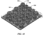
- a surface texture 106 is comprised of large scale structure 108, intermediate scale structure 110, and microscale structure 112.
- the microscale structure 112 is superimposed on intermediate scale structure 110, and this combination is superimposed on large scale structure 108.
- Large scale structure 108 has a characteristic dimension between 100 and 1000 microns.
- Intermediate scale structure 110 has a characteristic dimension between 25 and 100 microns.
- Microscale structure 112 has characteristic dimension between 1 and 25 microns.
- the size and shape of the retraction devices are application dependent.
- the size of retraction devices according to the invention can range from about 2" (50 mm) long by about 0.5" (12 mm) wide, for use inside the pericardium, to 10"14"(250-350 mm) long by 2"8" (50-200 mm) wide, for use in the abdominal cavity.
- the size of retraction device required for a given application depends on the application and the size of the patient.
- the basic embodiment of a Type II retraction device includes a single inflation chamber.
- a single chamber can be divided into a plurality of subchambers.
- the subchambers are isolated from one another, so that if one or more of them is accidentally punctured while the retraction device is in use, deflation of all of the retraction device can be avoided.
- Each subchamber can be equipped with its own additional inflation tube.
- each subchamber can be connected to an inflation manifold through a nonreturn valve.
- the manifold arrangement requires that each subchamber be individually deflated in preparation for withdrawing the retraction device from the body at the end of the treatment procedure.
- the main advantage of these subchambers, intercommunicating or separate, is to define a preferred geometry under inflation.
- FIG. 2 is a perspective view of a Type II device 200 with multiple inflation chambers.
- the main envelope 202 is made of a relatively inelastic and tough film of a plastic such as polypropylene, polyethylene, or polyurethane.
- a preferred material for the main envelope is a polyethylene and nylon composite.
- the wall thickness 204 of the main envelope 202 is typically from 0.5 to 5 mils (13 to 130 microns).
- the device thickness 206 of the microstructured arm 200 is between 1 mm and 5 mm.
- the device thickness 206 is limited by height 210 of inelastic members 208 that form the individual subchambers 212.
- Subchambers 212 run to a manifold 214. Air or liquid pressure is delivered by tube 216.
- the delivery tube 216 can be small and flexible with diameter 218 in the range 1 mm to 5 mm.
- the main inflation tube 216 allows an inflation gas to pass into and out of the subchambers 212.
- An inflation gas is typically air, nitrogen or carbon dioxide, although other suitable gases may be used.
- An inflation liquid is typically physiologic saline. Typical inflation gas pressures are in the range 0.3 to 0.7 psi (0.21 to 0.48 kPa), the preferred pressure being 0.5 psi (0.35 kPa). Once the device 200 is fully inflated, the inflation gas pressure can be reduced to about 0.3 psi (0.21 kPa).
- a retraction device according to the invention may be fitted with a tubular suction portion on the part of the retraction device that is lowermost when the retraction device is deployed in a cavity with liquid present.
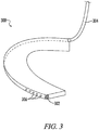
- FIG. 3 shows a Type I device with the suction feature attached.
- the suction portion of this aspect of the invention can be used with Type I and Type II retraction devices. Irrigation is often used when retraction is applied to a cavity environment. The irrigation is used to clear away debris. In the case of a surgical applications, the debris consists of blood and clotted elements. This fluid collects in the bottom of the cavity in the body created by the retraction device and needs to be cleared away.
- the suction portion 302 is integral to microstructured retractor 300.
- the bottom of the retraction device 300 is connected to a suction line 302 and removes such fluid during the treatment procedure, keeping the cavity clear of accumulated fluids.
- the suction portion 302 is a tubular appendage attached to the lowermost extremity of the retraction device.
- the suction portion can be made of the polyethylenenylon composite that is the preferred material for the main body of the retraction device. This material is sufficiently resilient that a tubular structure made from it can retain its open cross section under a low vacuum.
- One end of the suction portion 302 is closed; the other is connected to a thin wall polyethylene tube 304 that runs up the side of the retraction device to exit the body through the same incision through which the retraction device is delivered. Suction is delivered to the operative site through holes 306.
- Curvature can be formed within a tape like microstructured retractor arm.
- the curvature may have a radius of curvature that is substantially less than the length of the retractor such that when in the relaxed state the arm curls on itself at least 1 time.
- the preformed radius of curvature along with the stiffness of the materials used determine the normal force when the object enclosed in the retractor is larger than the radius of curvature. In most cases, the normal force is proportional to the ratio of the object's diameter to the retractors radius of curvature.
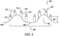
- a surface for an low normal force retractor surface 400 of the present invention possesses a hierarchical surface comprised of a large scale structure 402 with a plurality of protuberances 404 and depressions 406 disposed in a geometric pattern on at least one surface of a substrate 408, and a medium scale structure 410 disposed on at least one surface of the large scale level structure 402 is comprised of protuberances 412.
- the small scale structure 414 is similarly comprised of protuberances 416 and depressions 418 disposed on the medium scale structure 410.
- the large scale protuberances 404 should be high enough so that a hydrophilic component of a hydrophobic/hydrophilic contact mixture does not touch the large scale depressions between adjacent protuberances 404.
- the large scale protuberances 404 may comprise a height H of between about 25 to about 1000 microns and a diameter D of between about 25 to about 2000 microns, wherein the fraction of the surface area of the substrate 408 covered by the protuberances 404 may range from between about 0.1 to about 1.0.
- a fractal dimension is a statistical quantity that gives an indication of how completely a collection of structures appears to fill space, in the present case a plane, as one examines that structure on a multiplicity of spatial scales.
- Specifying a fractal dimension which is statistical in nature, does not necessarily indicate that the hierarchical structure is well defined by a mathematical equation.
- a random arrangement of structures within a specific scale possesses a higher fractal dimension than one in which the structure is mathematically described at all points on a surface.
- a random structure may possess an advantage in the aspect that an adhesive surface of the present invention has greater utility when interacting with a natural surface.
- a higher fractal dimension within a specific spatial scale may be achieved by applying to a substrate multiple pitch arrangements.
- the protuberances and depressions may be locally scaled with respect to the local pitch. Accordingly, the pitch may vary within a scale structure. In the practical realization of higher fractal dimension structures, the variation of the pitch may be describable by a mathematical equation, for example, a sinusoidal variation of pitch, which would have utility in mimicking natural surfaces.
- structures can be described as sharp-edged or rounded, and this feature is not typically captured by a fractal dimension.
- Another structural aspect not addressed by the above descriptive parameters is the degree of communication between structures.
- communication it is meant that a structure, such as a protuberance or a depression, has a spatial extent greater than the pitch. For example, a valley surrounding a protuberance may be connected to another valley surrounding another protuberance, thus the depressions are said to be communicating whereas the protuberances are not.
- the communication may range from 1 to about 1000, more particularly the communication may extend over the entire surface of the substrate.
- a scale of interaction is defined by the surface texture of the present low normal force retractor, and is typically hierarchical, and characterized by at least two spatial scales, one on the order of micrometers (microns) and another on the order of 100s of microns.
- the surface texture may induce one state with a large difference between preceding and receding contact angles (contact angle hysteresis), or alternatively another state with a small contact angle hysteresis. States of interest are known respectively as Wenzel and Cassie states.
- Each of the hierarchical spatial scales may induce separately a Wenzel or Cassie state, such that combinations are possible on a multiplicity of spatial scales.
- the Wenzel state can be discouraged by the use of curving communications between structures as opposed to straight line communication.
- higher hydrophobicity equates with lower propensity for a Wenzel transition.
- the hydrophobicity of a surface is enhanced by the placement of exterior corners around depressions. In some embodiments, this is achieved by the creation of additional pairs of adjacent depression walls that project into and are joined at the interior of the depression. In some embodiments this is achieved by designing an ordered array of depressions of a first hierarchy (examples: triangular, rectangular, pentagonal, or hexagonal shapes, regular or irregular; and further polygonal shapes defined generally by straight line segments).
- a second feature of smaller size and different hierarchical order is then superimposed on the depression wall of the first pattern.
- the method employed in creating such a structure may involve first emboss a large scale structure and then secondarily emboss additional smaller scale structure, preferably smaller scale structure embossed on larger scale structures.
- Water possesses a dipole structure which makes it attractive to any other substance that is charged. Molecules with a charge surplus localized at a specific location on the molecule renders that molecule hydrophilic.
- the charges can associate, and the bulk substance and possess a macroscopic charge. And in such macroscopic assemblages, such materials are strongly water attractive. And when those macroscopic charge localities are associated with surface texture, than a substance becomes superhydrophilic.
- superhydrophilic has various meanings in the literature, and in many cases simply refers to the rendering of a substance more hydrophilic, or a decrease in contact angle relative to a flat surface of the same substance.
- textured surfaces low normal force retractor is both shielded from contaminating debris and also is self-washing due to the stochastic attachment/detachment of water molecules from the surface.
- the methods of manufacture of textured surfaces low normal force retractors of the present invention include lithography, casting, extrusion/embossing, and any of several methods for transferring a texture to a surface. Methods for forming such hierarchical microstructured surfaces are described in U.S. Application No. 14/802,632 .
- a preferred method is embossing, where a polymeric substance is heated to a molten state and passed through dual rollers, at least one of which contains a negative image of the desired embossed structure.
- a small scale texture is embossed on a planar sheet. This embossed planar sheet is heated to a malleable but not fluid state and passed through dual rollers possessing a medium scale texture which impresses an inverse image. This process can be repeated multiple times.
- the medium scale texture is large relative to the small scale texture, thus the impression of the medium scale texture folds the small scale texture, making possible involute structures which would ordinarily not be possible with a lithography or casting method.
- the low normal force retractors of the present invention have three or more levels of textures assembled in a manner to yield a high surface area while maintaining a minimum spacing between textures to allow for liquid flow and penetration to promote in the first instance surface washing and in the second instance surface adhesion; and while maintaining a minimum structural strength obtained by keeping height to width aspect ratio of all features below a critical level at which material strength is exceeded.
- substrate 610 is constructed and arranged to focus on a series of rounded cavities forming valleys 617 extending inwardly into substrate 610 as the dominant feature with the associated peaks 615 disposed between valleys 617, and 614 indicates a second set of microfeatures.
- the surface of substrate 610 is continuously curving throughout sinusoidal waveform pattern area.
- sinusoidal waveform refers to a surface having a repetitive oscillation of rounded, nonflat curvature described by mathematical formulas incorporating trigonometric functions sine, cosine, tangent or exponential and power series functions. These mathematical formulas are used in computer aided design and computer aided manufacturing software to create texture surfaces using rapid prototyping, milling, electrical discharge machining or similar techniques to create a polymer or metal surface with the sinusoidal waveform texture features.
- the advantage of using mathematical formulas is that large numbers of rounded, nonflat features can be created rapidly in computer aided design and computer aided manufacturing software. Texture features of this type cannot be created using lithographic techniques.
- a selection of substrates 710 are shown having various sinusoidal waveform patterns that provide alternative curved surface texture features across substrate 710. These are for illustrative purposes only as example embodiments of substrate 710 and are not limiting of the present invention and the term sinusoidal waveform as used herein.
- a first set of texture features 712 includes dimensions selected from a size within a range of about 100 microns to about 1000 microns. More specifically as will be detailed herein below, the sinusoidal waveform is arranged so that first set of texture features 712 has sinusoidal rounded cavities of 750 microns, a pitch of 750 microns, and a depth of about 240 to 500 microns.
- a second set of texture features 814 and 914 are disposed on the surface of substrate 810 and 910.
- second set of texture features 814 is molded on first set of texture features 812 and 912 of substrate 810 and 910, respectively.
- substrate 810 or 910 is a compression molded polymeric material in which first and second sets of texture features 812, 814 and 912, 914 are formed on substrates 810 and 910, respectively, during a single molding step.
- First and second sets of texture features 812, 814 cooperate to increase the surface area and affect at least one of adhesion, friction, hydrophilicity and hydrophobicity of substrate 810 and 910.
- the compression molded polymeric material forming substrate 810 is an environmentally durable polymer.
- substrate 810 or 910 comprises polyethylenenylon copolymer.
- second set of microstructures 814 or 914 is selected from the group consisting of microstructured projections and microstructured cavities, and combinations thereof.
- second set of texture features 614 comprise microstructured cavities extending downwardly into substrate 610.
- second set of texture features 814, 914, 1014 and 1114 comprise microstructured projections extending upwardly from substrate 810, 910, 1010, and 110, respectively.
- the microstructured projections of said second set of texture features 814, 914, 1014 and 1114 comprise generally cylindrical pillars.
- the microstructured cavities of second set of texture features 614 comprise generally cylindrical recesses.
- second set of texture features 914 includes a series of microstructured projections on one of top surface 921 and bottom surface 923 of substrate 910, which then define a series of complementary microstructured cavities on the other of said top surface and said bottom surface 921, 923.
- second set of texture features 914 comprises microstructured cavities which project downwardly through substrate 910 from a top surface 921, they form complementary microstructured projections on the opposing bottom.
- the second set of texture features 514, 814 and 914 include at least a portion of texture features that extend along an axis normal to the curve of the sinusoidal waveform of substrate 510, 810 and 910 at a given point for the individual microstructure. In this way, the second set of texture features follow the curvature of first set of texture features 512, 812 and 912.
- the second set of texture features includes dimensions selected from a size within a range of about 10 microns to about 100 microns. Further, second set of texture features preferably have a height to width aspect ratio of less than 5, and a minimum spacing of 1 micron between each texture feature of said second set of texture features to maintain structural strength while allowing for liquid flow and penetration between the individual microstructures comprising second set of texture features.
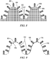
- a third set of texture features 820, 920, 1020 and 1120 may also be disposed on substrate 810, 910, 1010 and 1110, respectively.
- third set of texture features 820 is selected from the group consisting of microstructured projections and microstructured cavities, and combinations hereof.
- the microstructured projections of third set of texture features 820, 920, 1020 and 1120 comprise generally cylindrical pillars.
- the microstructured cavities of third set of texture features 620 comprise generally cylindrical recesses.
- the third set of texture features 620 are compression molded simultaneously with first and second sets of texture features 612, 614.
- the third set of texture features 620 have a height to width aspect ratio of less than 5, and a minimum spacing of 1 micron between each texture feature of third set of texture features 620 to maintain structural strength while allowing for liquid flow and penetration between said third set of texture features.
- the aspect ratio is smaller when devices are made of lower strength materials and larger when made from stronger materials.
- the spacing between features is smaller for less viscous liquids and larger for more viscous
- third set of texture features 520, 820 and 920 include at least a portion of texture features that extend along an axis normal to the curve of the sinusoidal waveform of substrate 10.
- the second and third sets of texture features extend along an axis normal to the curve of the sinusoidal waveform, the normal line to a curve is the line that is perpendicular to the tangent of the curve at a particular point.
- the second set of texture features 514, 814 and 914 is smaller than first set of texture features 512, 812 and 912, respectively, and third set of texture features 520, 820 and 920 is smaller than second set of texture features 514, 814 and 914, respectively.
- the third set of texture features includes dimensions selected from a size within a range of about 1 micron to about 10.
- third set of texture features 520, 820 and 920 are disposed on an end surface 522, 822 and 922 of second set of texture features 514, 814 and 914.
- Third set of texture features 520, 820 and 920 are disposed on first set of texture features 12 between second set of texture features 14.
- Third set of texture features 20 are disposed on an end surface 22 of second set of texture features 14, as well as, disposed on first set of texture features 12 between second set of texture features 14.
- a fourth set of texture features 1024 and 1124 may be disposed on side surfaces of second set of texture features 1014 and 1114, respectively.
- Fourth set of texture features 1024 and 1124 is selected from the group consisting of flutes 1016, 1116 and ribs 1018, 1118 and combinations thereof. Flutes (1016, 1116) and ribs (1018, 1118) run vertically along the height of the side surfaces on the outside circumference of each microstructure comprising said second set of texture features (1014, 1114).
- the fourth set of texture features preferably include dimensions selected from a size within a range of about 1 micron to about 10 microns.
- fourth set of texture features 1024 and 1124 are compression molded simultaneously with said first, second, and third sets of texture features into substrate 1010, 1110.
- flutes and/or ribs (1016, 1018, 1116, 1118) with features and spacing larger than 1 micron are added to the exterior of the cylindrical pillars or cavities defining second set of texture features (1014, 1114) to both add surface area and to increase structural resistance to bending and breaking.
- the spacing between individual microstructures of fourth set of texture features 1024, 1124 and between individual microstructures of second set of texture features (1014, 1114) is smaller for less viscous liquids and larger for more viscous liquids.
- Third set of texture features (1020, 1120) cover both the tops of pillars and bottoms of cavities and the area between the pillars or cavities defining second set of texture features 1314 in a substantially uniform manner. Together the second and third sets of texture features (1014, 1114), (1020, 1120) substantially increase the surface area exposed to the liquid covering the opposite surface from the substrate. Depending on the desired application, the first, second, third and fourth sets of texture features cooperate to increase the surface area of substrate (1010, 1110) to effect at least one of adhesion, friction, hydrophilicity and hydrophobicity of the substrate.
- Substrate (1010, 1110) has a surface adhesion with a sliding friction force of greater than 50 gr/cm2 when applied against a surface comprised of a hydrophobic/hydrophilic mixture. In a preferred embodiment, the substrate (1010, 1110) has a surface adhesion with a sliding friction force of about 325 gr/cm2 when applied against a surface comprised of a hydrophobic/hydrophilic mixture.
- the inventors In early studies, the inventors characterized rose petal structures and observed a 'rolling hill' effect in microstructures. Additionally, smaller microstructures were noted as 'hairs' that seemed to contribute strongly to the superhydrophobic effect. In order to best simulate this scheme, the inventors created sinusoidal designs as set forth herein that could reproduce and improve upon rounded microstructure effects seen naturally, starting with a sinusoidal waveform substrate with features from 300 microns diameter and pitch of 100 microns.
- the dimensions for the third set of texture features (1020, 1120) include in one embodiment pillars having 3 micrometers diameter, 6 micrometers pitch, and 5 micrometers tall.
- the second set of texture features (1014, 1114) in one embodiment includes fluted microstructure pillars that are at least 35 micrometers in diameter, 35 micrometers tall, and 10 micrometers spacing. When overlapped together, the second and third sets of micro features (1014, 1114, 1020, 1120) are formed along an axis normal to the surface of the sinusoidal waveform features. These are also maintained multidimensionally over the round.
- each microstructure of said first, second, third and fourth sets of texture features have a respective pitch, height/depth, and diameter, and wherein are arranged so that liquids penetrate between at least said first and second sets of texture features in a Wenzel fully wetted state when applied against a liquid covered surface to promote adhesion between the substrate and the adjacent surface.
- the sinusoidal waveform of the first set of texture features includes rounded peaks that facilitate pressure distribution across the substrate when pressed against a liquid covered surface.
- the second and third sets (1014, 1020, 1114, 1120) of texture features are uniformly distributed across the rounded peaks of first set of texture features to provide increased surface area to first set of texture features.
- the rounded peaks define areas of increased pressure when the substrate is applied against a liquid covered surface that promote a transition of liquid droplets from a suspended Cassie-Baxter state to a Wenzel fully wetted state among at least said first and second sets of texture features.
- first, second and third sets (1012, 1112, 1112, 1114) of texture features allow for liquid penetration to a Wenzel fully wetted state, while the fourth set of texture features (1024, 1124) are constructed and arranged to maintain superhydrophobic characteristics.
- the function of the second and third sets of texture features is to create a large surface area simultaneously with spacing wide enough the viscous liquids can flow through the structure at low pressure.
- Low pressure in this application is defined in the context of the weight associated with liquid droplets being sufficiently to create a Wenzel fully wetted state to promote adhesion of substrate 10 to an adjacent liquid covered surface.
- the microstructured surfaces of the present invention are designed to facilitate transitions from a Cassie-Baxter suspended droplet state to the Wenzel fully wetted state with a water droplet of greater than 10 texture liters in size.
- One function of the sinusoidal waveform of first set of texture features is to further increase the surface area while creating areas of increased pressure at the peaks of the features. These areas of increased surface area wet first, causing a rapid transition from the Cassie-Baxter suspended droplet state to the Wenzel fully wetted state.
- a second function of the sinusoidal waveform of first set of texture features is to keep the peak pressure low enough and to spread the pressure such that there is little or no penetration through the liquid layer on the surface into the underlying material.
- the second and third sets of texture features are spread uniformly over the sinusoidal waveform of first set of texture features and are normal to the curve of the surface. That is they are perpendicular to a surface tangent at each point of the microstructure on surface. This ensures that the maximum surface area is created in a structure that can be molded.
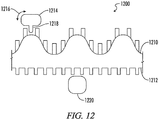
- FIG. 12 is a perspective view of a hybrid rotus Type I retraction device.
- Device 1200 is comprised of rose texture side 1210 and lotus texture side 1212.
- a rose texture 1210 is characterized by the geometry of a water drop 1214 wherein drop 1214 takes on a spherical shape 1216 characteristic of a superhydrophobic surface. Drop 1214 is immobilized on the surface 1210 due to wicking geometry 1218.
- a lotus texture 1212 is characterized by the geometry of water drop 1220 wherein the shape is spherical with the absence of a wicking structure analogous to feature 1518. Drop 1220 resists adhesion to surface 1212, and readily rolls off the surface.
- FIG. 13 is a side view of a corrugated Type II retraction device. It should be understood a manually actuated Type I version is also possible.
- Device 1300 can be in two configurations 1310 and 1312. Configuration 1310 is a rose texture configuration and configuration 1312 is a lotus texture configuration. Thus, when in configuration 1610 device 1300 is adhesive, and in configuration 1312 it slides easily.
- Device 1300 in the corrugated state 1310 has first structure 1314 and second structure 1316.
- An inflation member 1320 causes device 1600 to move in direction 1318 to transform into configuration 1312 when pressurized.
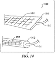
- FIG. 14 is a perspective view of a area changing Type II retraction.
- Device 1400 has surface texture 1314 and can be in two configurations 1310 and 1312.
- Configuration 1310 is a flat configuration with maximum surface area in contact with a planar surface and configuration 1612 is an inflated configuration with minimum surface area.
- An inflation member 1316 causes device 1300 to transform into configuration 1312 when pressurized.
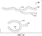
- FIG. 15 is a side view of a hybrid area changing Type I retraction device 1500 where the textured area 1514 is unchanging.
- Device 1500 assumes two bistable configurations 1510 and 1512.
- rose petal texture 1514 is the only surface presented to another surface to which device 1500 is to adhere.
- the contact surface area in configuration 1510 is the sum of the areas of 1514.
- the area 1516 is smooth, and the area of configuration 1512 is larger than the area of configuration 1510.
- the area of configuration 1512 is the sum of the areas 1514 and 1516.
- Configuration 1512 is achieved by pulling configuration 1510 in the directions 1518.
- FIG. 16 is a perspective view of a pincer movement Type II retraction device 1600.
- Device 1600 has a relaxed, conformable state 1610 and rigid pinching state 1612. Transformation from state 1610 to state 1612 is achieved by inflation element 1616.
- Features 1614 comprise a rose petal adhesive surface.
- Fig. 17 depicts a retractor according to an embodiment of the invention, the retractor 1701 comprised of arm 1703 and surgical anchor 1705
- the surgical anchor 1705 enables the surgeon to anchor the retractor 1701 to perioperative surgical dressing.
- the proximal end 1707 of the retractor 1701 possesses superhydrophobic surface 1019.
- superhydrophobic surface are depicted and described above.
- the retractor may comprise an inflation element 1711 comprised on a hallow section 1713 that can be pressurized via tube 1715. As depicted, when hallow section 1713 is inflated the retractor becomes rigid and straight along direction 1717.
- the retractor may comprise a suction bladder comprised of a series of holes 1719 providing throughput from tissue contacting side 1721 to internal suction volume 1723.
- the suction bladder is comprised of the tissue contacting side 1721 and an external side 1725.
- External side 1725 may possess tabs 1726 to which a surgeon may suture a stay line or grasp to position retractor 1 relative to a tissue surface.
- a suction tube 1727 attached to the suction bladder provides suction and draws tissue fluid 1729 into the suction bladder.
- retractor 1 may possess a preformed shape such that the width 1731 is straight and the length 1733 is curved with radius of curvature 1735.
- the retractor 1701 possesses a tissue contacting surface 1721 which is corrugated 37.
- the corrugation frequency 1739 can be adjusted through inflation element 1711, such that increased inflation decreases frequency 1739 and increases length 1733.
Landscapes
- Health & Medical Sciences (AREA)
- Life Sciences & Earth Sciences (AREA)
- Surgery (AREA)
- Heart & Thoracic Surgery (AREA)
- Engineering & Computer Science (AREA)
- Biomedical Technology (AREA)
- Nuclear Medicine, Radiotherapy & Molecular Imaging (AREA)
- Medical Informatics (AREA)
- Molecular Biology (AREA)
- Animal Behavior & Ethology (AREA)
- General Health & Medical Sciences (AREA)
- Public Health (AREA)
- Veterinary Medicine (AREA)
- Surgical Instruments (AREA)
- Materials For Medical Uses (AREA)
Description
- The present disclosure relates to surgical retractors comprising microtextured surfaces. The surgical retractors comprise a microtextured surface on one or more portions of the retractor, thereby advantageously providing immobilizing or positioning forces to a wet tissue surface while preventing or minimizing damage or trauma to the tissue.
- There are many objects, natural and manmade, that are characterized by possessing a relatively durable surface enclosing delicate structures that would be adversely altered by a force applied normal to the durable surface and unaltered by a force applied tangent or in plane to the durable surface. Therefore, there is a need in the art for a retracting device that allows these objects to be immobilized, relocated, or positioned without causing internal damage by the force applied by the retractor.
- A non-limiting example is the traction of living tissue during a medical procedure such as a surgery. In these procedures it is frequently necessary to retract organs to gain access to a target organ or tissue to be treated or observed. In other procedures, to gain access to the organ or tissue to be treated or observed, it is necessary to separate the organ to be treated from tissue surrounding it. For example, to be able to observe the outer surface of the heart, it must be separated from the pericardium. To obtain the necessary retraction, current laparoscopic procedures use several small retractors inserted through a plurality of incisions. Because such retractors have a relatively small surface area, they tend to damage and/or cause trauma to the retracted organs or tissue by applying localized normal forces.
- Wenzel, Cassie and Wenzel-Cassie states describes wetting phenomena between hydrophobic and hydrophilic components of a mixture at a surface interface. The interaction of a solid textured surface with water in a gaseous environment is described by the Cassie-Baxter model. In this model, air is trapped in the microgrooves of a textured surface and water droplets rest on a compound surface comprising air and the tops of microprotrusions. The importance of a fractal dimension between multiple scales of texture is well recognized and many approaches have been based on the fractal contribution, i.e., the dimensional relationship between different scales of texture.
- However, regardless of the material (organic or inorganic) used and geometric structure of a surface texture (particles, rod arrays, or pores), multiple scales of texture in combination with low surface energy would be needed to obtain the so called superhydrophobic surfaces. Superhydrophobicity is variously reported as a material exhibiting a contact angle with water that is greater than contact angles achievable with smooth but strongly hydrophobic materials. The general consensus for the minimum contact angle for a superhydrophobic substance is 150 degrees.
- A hydrophobic surface repels water. The hydrophobicity of a surface can be measured, for example, by determining the contact angle of a drop of water on a surface. The contact angle can be measured in a static state or in a dynamic state. A dynamic contact angle measurement can include determining an advancing contact angle or a receding contact angle with respect to an adherent species such as a water drop. A hydrophobic surface having a small difference between advancing and receding contact angles (i.e., low contact angle hysteresis) results in surfaces with low resistance to in plane translation (low adherence). Water can travel across a surface having low contact angle hysteresis more readily than across a surface having a high contact angle hysteresis, thus the magnitude of the contact angle hysteresis can be equated with the amount of energy needed to move a substance.
- The classic motivation from nature for surface texture research is the lotus leaf, which is superhydrophobic due to a hierarchical structure of convex cell papillae and randomly oriented hydrophobic wax tubules, which have high contact angles and low contact angle hysteresis with water and show strong self-cleaning properties. A lesser known motivation from nature is the red rose petal, with a hierarchical structure of convex cell papillae ornamented with circumferentially arranged and axially directed ridges, which have a moderate contact angle and high angular contact difference.
- The contact angle is a measure of the amount of water directly in contact with the textured surface, while the contact angle hysteresis is a measure of the degree to which water is mobile on a surface. The evolutionary motivation for each of these states is quite distinct. In the case of the lotus leaf, and botanical leaves generally, minimal contact with water and high water mobility results in preferential adherence of the water to particulate contaminants, which are cleared from the leave as the water runs off. This serves to reduce to the amount of light absorbance by surface contaminants, and increase photosynthetic efficiency. In the case of the rose petal, and botanical petals generally, most pollinators are attracted to high tension water sources which provide ready accessibility without drowning the insect. Thus, high contact angle paired with high contact angle hysteresis is preferred where the evolutionary stimulus is reproduction in botanicals, and high contact angle paired with low contact angle hysteresis is preferred where the evolutionary stimulus is metabolism and growth.
- Considering for a moment a single texture scale, when water is placed on a textured surface it can either sit on the peaks of the texture or wick into the valleys. The former is called the Cassie state, and the later the Wenzel state. When the Wenzel state is dominant, both the contact angle and contact angle hysteresis increase as the surface roughness increases. When a roughness factor exceeds a critical level, however, the contact angle continues to increase while the hysteresis starts decreasing. At this point, the dominant wetting behavior changes, due to an increase in the amount of hydrophobic component (in this case, air) at the interface between the surface and water droplet. When multiple texture scales are employed, some can be Wenzel and others Cassie. Of the two states, the Wenzel state has the lower contact angle, higher contact angle hysteresis and lower mobility. In mixed Wenzel-Cassie states it is possible to have high contact angle and high contact angle hysteresis. However, the hydrophobicity of a textured solid relative to the interacting hydrophobic and hydrophilic components is very important.
- In the botanical world, most textured surfaces occur on substrates that are hydrophobic. However, when a hydrophobic fluid replaces the water, a Cassie state can easily be converted to a Wenzel state. This is not always the case, and depends on the vapor pressure and viscosity of the hydrophobic material and how quickly the air trapped in the surface texture can be dissipated.
- Various attempts have been made to achieve hydrophobic coatings and surfaces, as follows:
U.S. Pat. No. 6,994,045 describes a superhydrophobic coating acting as a substrate for a gaseous lubricant of very low viscosity, has a hierarchical fractal structural of the surface wherein the forms of the first hierarchical level are located at the coating's substrate, and the forms of each successive hierarchical levels are located on the surface of the previous hierarchic level and the forms of individual higher hierarchic levels reiterate the forms of the lower hierarchic levels.U.S. Pat. No. 7,419,615 discloses a method of forming a superhydrophobic material by mixing a hydrophobic material with soluble particles to form a mixture.U.S. Pat. No. 7,887,736 discloses a superhydrophobic surface repeatedly imprinted using a template, so that mass production of a superhydrophobic polymer over a large area can be economically implemented.U.S. Pub. No. 20030147932 discloses a self-cleaning or lotus effect surface that has antifouling properties.U.S. Pub. No. 20060029808 discloses a coating that can remain superhydrophobic after being immersed in water for one week.U.S. Pub. No. 20080015298 discloses a superhydrophobic coating composition.U.S. Pub. No. 20080241512 discloses a method of depositing layers of materials to provide superhydrophilic surface properties, or superhydrophobic surface properties, or combinations of such properties at various locations on a given surface.U.S. Pub. No. 20090011222 discloses a method of applying lotus effect materials as a superhydrophobic protective coating for various system applications, as well as the method of fabricating/preparing lotus effect coatings.U.S. Pub. No. 20090076430 discloses a bandage that includes a material, which can be breathable, having a first surface, and a plurality of superhydrophobic particles attached to the first surface. The material can have a second surface opposite the first surface that is hydrophilic.U.S. Pub. No. 20090227164 discloses a superhydrophobic coating of a nonwoven material is coated with a spongy mesh structure in the micro and nano ranges.U.S. Pub. No. 20100112286 discloses control and switching of liquid droplet states on artificially structured superhydrophobic surfaces.U.S. Pub. No. 20100021692 discloses a method of manufacturing a multiscale (hierarchical) superhydrophobic surface is provided. The method includes texturing a polymer surface at three size scales, in a fractal-like or pseudo fractal-like manner, the lowest scale being nanoscale and the highest microscale.U.S. Pub. No. 20100028604 discloses a superhydrophobic structure comprise a substrate and a hierarchical surface structure disposed on at least one surface of the substrate, wherein the hierarchical surface structure comprises a microstructure comprising a plurality of microasperities disposed in a spaced geometric pattern on at least one surface of the substrate.U.S. Pub. No. 20110077172 discloses a method of localized deposition of a material and includes a superhydrophobic substrate comprising raised surface structures.WO2005/042646 describes nanocoatings.US2014/200679 describes implants with a hierarchical surface structure. - Accordingly, it is an object of the present invention to provide a retractor in accordance with claim 1.
- The present disclosure relates to a low normal force retraction device that mechanically retracts surfaces or objects by applying a low-slip microtextured surface. The invention relates to a retractor according to claim 1. Further embodiments are recited in the dependent claims. In its simplest embodiments, the retraction device is comprised of one or more arms, jaws or tentacles for retracting an object. These features will be referred to collectively as "arms". The arms in some instances are soft and flexible in a normal direction, and substantially non-distensible in a tangent direction. In other embodiments, one or more arms may be rigid so as to provide a lifting or supportive function, such rigid arms will typically have larger surface area to minimize the normal force per unit surface area during a lifting or retention application.
- In other embodiments, the retraction device may consist of a single flexible arm with a microtextured surface that is particularly useful for encircling an object to be retracted. Retraction in this case may include folding one portion of an object over another portion of the same object and holding the folded object in this configuration. When the retraction device is a single flexible arm, it maybe further equipped with other fastening features such as holes or hooks that can be used to anchor the arm to an external anchoring structure. These additional fastening features may be employed in coupling two or more single arm retractors together. These additional fastening features may include without limitation lockable graspers, such as a pliers or forceps.
- In the following description, the term "microtextured surface" will be used to mean a surface with a hierarchical structure comprised of microstructures of various spatial scales superimposed to form a single surface with texture on at least two spatial scales. In some embodiments, the microtextured surface comprises three, four or more spatial scales, preferably three or four spatial scales. Examples of microtextured surfaces useful in the present retractors include superhydrophobic surfaces resembling natural rose petal texture. Other examples include surfaces whose contact hysteresis with living tissue is greater than 5 degrees. These surfaces are characterized by the production of a Wenzel-Cassie interface when the microtextured surface comes into contact with a wet or lubricious surface. Other, hierarchical microtextured surfaces include those resembling the surface texture of a lotus leaf, wherein the interface is a Cassie-Baxter type interface.
- A microtextured surface may comprise a hybrid of the above-mentioned rose and lotus surface textures wherein one portion is rose-like and other portions are lotus-like, to obtain a "rotus" surface. An arm of the present invention may have a lotus surface on one side and a rose surface on the other side. In the following description, the word "normal force" will be used to mean a force per unit surface area or pressure, wherein the force is orthogonal or normal to the surface area. The surface area typically will refer to the textured surface area of the microtexture arm, and the normal force that force orthogonal to the textured surface of the arm that is applied through contact with an object to be retracted. Accordingly, the normal force can generally be decreased by increasing the surface area of the arm. In some instances it may be useful to be able to alter the surface area of the microtextured arm. Accordingly, the arm has a corrugated structure that can be made less corrugated to increase the arm's surface area. Other retractors include inflation or distention of the arm. In still other embodiments, the areas of increasing area are decoupled from microstructured areas where the microstructure spatial dimensions are unaltered by the act of increasing the surface area of the arm. The inflation aspect may be used to alter the rigidity of the microtextured arm, or alter its morphology. For example, inflation of two microstructured arms may be configured to create a pincer movement that provides for the alteration of the applied normal forces.
- A microtextured retraction device according to the invention, such a retraction device being designated generally as a Type I retraction device, provides retraction by a Wenzel-Cassie effect alone wherein the microtextured surface naturally adheres itself by a hydrophobic interaction with wet surfaces. Type I devices typically have fixed mechanical properties, such as elasticity, rigidity, modulus, and the like. Type II devices include auxiliary components for altering these characteristics and the relation between arms. For example, stiffening an arm or bring two arms to a preferred orientation by inflation. Inflation includes both gaseous and liquid inflation. In gaseous inflation, pressure is controlled, while in liquid inflation, volume is controlled. Composite inflation structures are possible. A first inflation chamber can be formed between two opposing surfaces of a tube-shape microtextured arm, wherein bridging structures between opposing surfaces maintains an approximately flat tape-shaped microtextured arm under inflation. An additional inflatable chamber, which forms an inner smaller tubular structure inside the first chamber of the microtextured arm. Under inflation, this second chamber may provide a preferred curved structure to the microtextured arm. The second inflatable chamber is normally inflated after the main inflatable chamber of the retraction device has been inflated, and the retraction device has produced its desired retraction effect. Such an additional inflatable chamber is smaller and less powerful than the main inflatable chamber. Inflating the additional chamber alone would not always produce sufficient force to provide the desired retraction of the organ. However, the inflated additional chamber provides enough force to maintain an object that has been retracted by the more powerful main inflatable chamber in its retracted position. The additional inflatable chamber is thus able to maintain the retraction effect of the retraction device after the retraction effect of the main inflatable chamber has been destroyed by piercing an aperture in the envelope of the main chamber to provide access to the object to be treated.
- A Type I or a Type II retraction device according to the invention may be provided, with tabs attached to the surfaces of the microtextured arms of the device. The tabs are gripped with a suitable gripping tool to adjust the position and orientation of the retraction device relative to the tissue to be treated.
- When in its first state prior to actuation, markings may be provided on its surface to aid proper orientation prior to actuation or similar markings intended to indicate regions of different surface texture. One configuration of the corrugation may provide an adhesive Wenzel-Cassie surface and in another configuration of the corrugation may provide a low friction Cassie-Baxter surface. This feature may be used to release a retracted object in a manner that would reduce potential damage to the object if release was attempted while in the Wenzel-Cassie state. For example, a Type I device could be in a first adhesive state and subsequently made nonadhesive by irreversibly deforming the microstructure arm by applying a tangent stretching motion to the microtextured arm. In a Type II device, the same can be achieved reversibly by an inflation action.
- An arm may be incorporated with a suction tube for removing free liquid at the retraction site. Alternatively, a microstructured arm may be fitted with an attachment for such a suction tube. In the case of retraction during a surgical procedure, suction aspect is connected to the operating room suction line and allows continuous or intermittent drainage of fluid that collects in the bottom of a surgical cavity created by the retraction device during laparoscopic surgery.
-
-
FIG. 1 is a cross-sectional view of a superhydrophobic Wenzel-Cassie surface; -
FIG. 2 is a perspective view of a tape-like Type II inflatable retraction device; -
FIG. 3 is a perspective view of a Type I retraction device fitted with a suction means. -
FIG. 4 depicts a microstructured surface useful for a low normal force retractor. -
FIG. 5 depicts a low normal force retractor surface. -
FIG. 6 depicts an inverse surface. -
FIGS. 7A-7D depict a selection ofsubstrates 710 having various sinusoidal waveform patterns that provide alternative curved surface texture features acrosssubstrate 710 -
FIG. 8 depicts a side view of a microstructured surface on a substrate according to the present disclosure having a second set of features disposed on the surface of the substrate. -
FIG. 9 depicts a side view of a microstructured surface on a thin substrate. -
FIG. 10 depicts a perspective view of a microstructured surface having a fourth set of microfeatures. -
FIG. 11 depicts a schematic top view of a microstructured surface having a fourth set sets of microfeatures. -
FIG. 12 is a perspective view of a hybrid rotus Type I retraction device. -
FIG. 13 is a perspective view of a corrugated Type II retraction device. -
FIG. 14 is a perspective view of a area changing Type II retraction device. Device 1400 hassurface texture 1414 and can be in twoconfigurations Configuration 1410 is a flat configuration with maximum surface area in contact with a planar surface andconfiguration 1612 is an inflated configuration with minimum surface area. Thus, when in configuration 1710 device 1700 is adhesive, and inconfiguration 1412 it slides more easily. Aninflation member 1416 causes device 1400 to transform intoconfiguration 1412 when pressurized. -
FIG. 15 is a side view of a hybrid area changing TypeI retraction device 1500 where thetextured area 1514 is unchanging.Device 1500 assumes twobistable configurations configuration 1510 rosepetal texture 1514 is the only surface presented to another surface to whichdevice 1500 is to adhere. The contact surface area inconfiguration 1510 is the sum of the areas of 1514. Thearea 1516 is smooth, and the area ofconfiguration 1512 is larger than the area ofconfiguration 1510. The area ofconfiguration 1512 is the sum of theareas Configuration 1512 is achieved by pullingconfiguration 1510 in thedirections 1518. -
FIG. 16 is a perspective view of a pincer movement Type IIretraction device 1600.Device 1600 has a relaxed, conformable state 1610 andrigid pinching state 1612. Transformation from state 1610 tostate 1612 is achieved byinflation means 1616.Features 1614 are comprise a rose petal adhesive surface. -
FIG. 17 depicts a retractor according to an embodiment of the invention, the retractor comprising an arm having the microtextured surface of the present disclosure disposed on a portion thereof. -
FIG. 1 shows a vertical view of afirst embodiment 100 of a retraction device. This type of retraction device is essentially fixed in its mechanical and geometrical aspects and will be designated as a Type I retraction device. The retraction device is shown in its flat condition, and it is understood that the device has sufficient flexibility that it can be made to conform to the surface of an object to be retracted. Theretraction device 100 comprises afirst side 102 and asecond side 104.Retraction device 100 is made of a relatively inelastic and tough film of a plastic such as polypropylene, polyethylene, or polyurethane. The preferred material is a polyethylene and nylon composite. The thickness of theretraction device 100 is typically from 0.5 to 5 mm. Asurface texture 106 is comprised oflarge scale structure 108,intermediate scale structure 110, andmicroscale structure 112. Themicroscale structure 112 is superimposed onintermediate scale structure 110, and this combination is superimposed onlarge scale structure 108.Large scale structure 108 has a characteristic dimension between 100 and 1000 microns.Intermediate scale structure 110 has a characteristic dimension between 25 and 100 microns.Microscale structure 112 has characteristic dimension between 1 and 25 microns. - Generally, the size and shape of the retraction devices are application dependent. For example, in a surgical application, the size of retraction devices according to the invention can range from about 2" (50 mm) long by about 0.5" (12 mm) wide, for use inside the pericardium, to 10"14"(250-350 mm) long by 2"8" (50-200 mm) wide, for use in the abdominal cavity. The size of retraction device required for a given application depends on the application and the size of the patient.
- The basic embodiment of a Type II retraction device includes a single inflation chamber. In alternative embodiments, a single chamber can be divided into a plurality of subchambers. The subchambers are isolated from one another, so that if one or more of them is accidentally punctured while the retraction device is in use, deflation of all of the retraction device can be avoided. Each subchamber can be equipped with its own additional inflation tube. Alternatively, each subchamber can be connected to an inflation manifold through a nonreturn valve. The manifold arrangement requires that each subchamber be individually deflated in preparation for withdrawing the retraction device from the body at the end of the treatment procedure. The main advantage of these subchambers, intercommunicating or separate, is to define a preferred geometry under inflation.
-
FIG. 2 is a perspective view of a Type IIdevice 200 with multiple inflation chambers. Themain envelope 202 is made of a relatively inelastic and tough film of a plastic such as polypropylene, polyethylene, or polyurethane. A preferred material for the main envelope is a polyethylene and nylon composite. Thewall thickness 204 of themain envelope 202 is typically from 0.5 to 5 mils (13 to 130 microns). When inflated, thedevice thickness 206 of themicrostructured arm 200 is between 1 mm and 5 mm. Thedevice thickness 206 is limited byheight 210 ofinelastic members 208 that form theindividual subchambers 212.Subchambers 212 run to amanifold 214. Air or liquid pressure is delivered bytube 216. Thedelivery tube 216 can be small and flexible with diameter 218 in the range 1 mm to 5 mm. Themain inflation tube 216 allows an inflation gas to pass into and out of thesubchambers 212. An inflation gas is typically air, nitrogen or carbon dioxide, although other suitable gases may be used. An inflation liquid is typically physiologic saline. Typical inflation gas pressures are in the range 0.3 to 0.7 psi (0.21 to 0.48 kPa), the preferred pressure being 0.5 psi (0.35 kPa). Once thedevice 200 is fully inflated, the inflation gas pressure can be reduced to about 0.3 psi (0.21 kPa). - A retraction device according to the invention may be fitted with a tubular suction portion on the part of the retraction device that is lowermost when the retraction device is deployed in a cavity with liquid present.
FIG. 3 shows a Type I device with the suction feature attached. The suction portion of this aspect of the invention can be used with Type I and Type II retraction devices. Irrigation is often used when retraction is applied to a cavity environment. The irrigation is used to clear away debris. In the case of a surgical applications, the debris consists of blood and clotted elements. This fluid collects in the bottom of the cavity in the body created by the retraction device and needs to be cleared away. Thesuction portion 302 is integral tomicrostructured retractor 300. The bottom of theretraction device 300 is connected to asuction line 302 and removes such fluid during the treatment procedure, keeping the cavity clear of accumulated fluids. In the example shown, thesuction portion 302 is a tubular appendage attached to the lowermost extremity of the retraction device. The suction portion can be made of the polyethylenenylon composite that is the preferred material for the main body of the retraction device. This material is sufficiently resilient that a tubular structure made from it can retain its open cross section under a low vacuum. One end of thesuction portion 302 is closed; the other is connected to a thinwall polyethylene tube 304 that runs up the side of the retraction device to exit the body through the same incision through which the retraction device is delivered. Suction is delivered to the operative site throughholes 306. - Curvature can be formed within a tape like microstructured retractor arm. For example, the curvature may have a radius of curvature that is substantially less than the length of the retractor such that when in the relaxed state the arm curls on itself at least 1 time. The preformed radius of curvature along with the stiffness of the materials used determine the normal force when the object enclosed in the retractor is larger than the radius of curvature. In most cases, the normal force is proportional to the ratio of the object's diameter to the retractors radius of curvature.
- Referring to
FIG. 4 , generally a surface for an low normalforce retractor surface 400 of the present invention possesses a hierarchical surface comprised of alarge scale structure 402 with a plurality ofprotuberances 404 anddepressions 406 disposed in a geometric pattern on at least one surface of asubstrate 408, and amedium scale structure 410 disposed on at least one surface of the largescale level structure 402 is comprised ofprotuberances 412. Thesmall scale structure 414 is similarly comprised ofprotuberances 416 anddepressions 418 disposed on themedium scale structure 410. Thelarge scale protuberances 404 should be high enough so that a hydrophilic component of a hydrophobic/hydrophilic contact mixture does not touch the large scale depressions betweenadjacent protuberances 404. In the embodiment ofFIG. 4 , thelarge scale protuberances 404 may comprise a height H of between about 25 to about 1000 microns and a diameter D of between about 25 to about 2000 microns, wherein the fraction of the surface area of thesubstrate 408 covered by theprotuberances 404 may range from between about 0.1 to about 1.0. Themedium scale protuberances 412 may comprise aheight 420 of between 5 to about 25 microns and adiameter 422 of between 5 to about 50 microns, wherein the fraction of the surface area of thesubstrate 408 covered by theprotuberances 412 may range from between about 0.1 to about 0.9. Thesmall scale structure 414 may be disposed primarily on themedium scale structure 412. The arrangement of hierarchical structures may be geometric and describable generally with a mathematical equation. Alternatively, the hierarchical structures may be randomly disposed, possibly with varying pitch, which is more typical of natural structures. The arrangement of hierarchical structure can generally be described by a fractal dimension. - A fractal dimension is a statistical quantity that gives an indication of how completely a collection of structures appears to fill space, in the present case a plane, as one examines that structure on a multiplicity of spatial scales. Specifying a fractal dimension, which is statistical in nature, does not necessarily indicate that the hierarchical structure is well defined by a mathematical equation. Generally, a random arrangement of structures within a specific scale possesses a higher fractal dimension than one in which the structure is mathematically described at all points on a surface. Thus, a random structure may possess an advantage in the aspect that an adhesive surface of the present invention has greater utility when interacting with a natural surface. A higher fractal dimension within a specific spatial scale may be achieved by applying to a substrate multiple pitch arrangements. The protuberances and depressions may be locally scaled with respect to the local pitch. Accordingly, the pitch may vary within a scale structure. In the practical realization of higher fractal dimension structures, the variation of the pitch may be describable by a mathematical equation, for example, a sinusoidal variation of pitch, which would have utility in mimicking natural surfaces.
- Generally, structures can be described as sharp-edged or rounded, and this feature is not typically captured by a fractal dimension. Another structural aspect not addressed by the above descriptive parameters is the degree of communication between structures. By communication, it is meant that a structure, such as a protuberance or a depression, has a spatial extent greater than the pitch. For example, a valley surrounding a protuberance may be connected to another valley surrounding another protuberance, thus the depressions are said to be communicating whereas the protuberances are not. The communication may range from 1 to about 1000, more particularly the communication may extend over the entire surface of the substrate. These structures are constructed with the purpose of creating Wenzel and Cassie states, on a multiplicity of scales, when the low normal force retractor of the present invention comes in contact with a hydrophobic/hydrophilic contact mixture.
- A scale of interaction is defined by the surface texture of the present low normal force retractor, and is typically hierarchical, and characterized by at least two spatial scales, one on the order of micrometers (microns) and another on the order of 100s of microns. The surface texture may induce one state with a large difference between preceding and receding contact angles (contact angle hysteresis), or alternatively another state with a small contact angle hysteresis. States of interest are known respectively as Wenzel and Cassie states. Each of the hierarchical spatial scales may induce separately a Wenzel or Cassie state, such that combinations are possible on a multiplicity of spatial scales.
- These states are phenomena between hydrophobic and hydrophilic components of a mixture residing at a textured surface interface. In the Cassie state the adherent textile is resistant to hydrophobic debris adhesion, for example oil in an oil water mixture. In the Wenzel state the implant is reversibly adherent to a hydrophilic surface, for example a wet or ice surface. In hybrid Cassie-Wenzel states, where one texture scale is Wenzel and the other is Cassie, the retractor can be both localizing to a wet surface and resistant to hydrophobic contaminants such as fats.
- The interaction of a solid textured surface with water in a gaseous environment is described by the Cassie-Baxter model. In this model, air is trapped in the microgrooves of a textured surface and water droplets rest on a compound surface comprising air and the tops of microprotrusions. The importance of a fractal dimension between multiple scales of texture is well recognized and many approaches have been based on the fractal contribution, i.e., the dimensional relationship between different scales of texture.
- However, regardless of the material (organic or inorganic) used and geometric structure of the surface texture (particles, rod arrays, or pores), multiple scales of texture in combination with low surface energy has been required to obtain the so called superhydrophobic surfaces. Superhydrophobicity is variously reported as a material exhibiting a contact angle with water that is greater than contact angles achievable with smooth but strongly hydrophobic materials. The consensus for the minimum contact angle for a superhydrophobic substance is 150 degrees, so in this context some of the embodiments of the present invention are not strictly superhydrophobic, although this option is not excluded The reason for this is that a Wenzel-Cassie state lies in its hydrophobicity between nontextured surfaces and surface that generate a Cassie-Baxter interface. In optimizing the adherence of the textiles of the present invention superhydrophobicity is just one aspect of a number of interesting texture controlled mechanisms, and in this context the contact angle is less important than the contact angle hysteresis.
- It is known in the art that the transition to the Wenzel state can be discouraged by the use of sharp cornered features in the plane of the surface. However, the occurrence of sharp cornered structures in natural structures, such as rose petals, is less common. Natural structures tend to possess rounded surface features, especially radiused or filleted corners. In nature, resistance to conversion to a Wenzel state seems to involve the creation of involute rounded structures rather than sharp edges. By involute it is meant concavity oriented in a line not orthogonal to the substrate surface. Such structures are difficult to create by an etching or casting method, but can readily be created by an embossing method that entails folding of a structure.
- Similarly, the Wenzel state can be discouraged by the use of curving communications between structures as opposed to straight line communication. In most cases, higher hydrophobicity equates with lower propensity for a Wenzel transition. The hydrophobicity of a surface is enhanced by the placement of exterior corners around depressions. In some embodiments, this is achieved by the creation of additional pairs of adjacent depression walls that project into and are joined at the interior of the depression. In some embodiments this is achieved by designing an ordered array of depressions of a first hierarchy (examples: triangular, rectangular, pentagonal, or hexagonal shapes, regular or irregular; and further polygonal shapes defined generally by straight line segments).
- A second feature of smaller size and different hierarchical order is then superimposed on the depression wall of the first pattern. The method employed in creating such a structure may involve first emboss a large scale structure and then secondarily emboss additional smaller scale structure, preferably smaller scale structure embossed on larger scale structures.
- Water possesses a dipole structure which makes it attractive to any other substance that is charged. Molecules with a charge surplus localized at a specific location on the molecule renders that molecule hydrophilic. In the case of polymers, the charges can associate, and the bulk substance and possess a macroscopic charge. And in such macroscopic assemblages, such materials are strongly water attractive. And when those macroscopic charge localities are associated with surface texture, than a substance becomes superhydrophilic. The term superhydrophilic has various meanings in the literature, and in many cases simply refers to the rendering of a substance more hydrophilic, or a decrease in contact angle relative to a flat surface of the same substance. Here, it is meant the accentuation of surface charge and surface energy such that water is always bonded to the substrate surface, even though any particular water molecule may have a short residence time on the polymer surface. This has a commercial advantage in that the adherent surface of the low normal force retractor is both shielded from contaminating debris and also is self-washing due to the stochastic attachment/detachment of water molecules from the surface. The methods of manufacture of textured surfaces low normal force retractors of the present invention include lithography, casting, extrusion/embossing, and any of several methods for transferring a texture to a surface. Methods for forming such hierarchical microstructured surfaces are described in
U.S. Application No. 14/802,632 . - A preferred method is embossing, where a polymeric substance is heated to a molten state and passed through dual rollers, at least one of which contains a negative image of the desired embossed structure. A small scale texture is embossed on a planar sheet. This embossed planar sheet is heated to a malleable but not fluid state and passed through dual rollers possessing a medium scale texture which impresses an inverse image. This process can be repeated multiple times. The medium scale texture is large relative to the small scale texture, thus the impression of the medium scale texture folds the small scale texture, making possible involute structures which would ordinarily not be possible with a lithography or casting method.
- The low normal force retractors of the present invention have three or more levels of textures assembled in a manner to yield a high surface area while maintaining a minimum spacing between textures to allow for liquid flow and penetration to promote in the first instance surface washing and in the second instance surface adhesion; and while maintaining a minimum structural strength obtained by keeping height to width aspect ratio of all features below a critical level at which material strength is exceeded.
- Referring to
FIG. 5 , a low normalforce retractor arrangement 500 on a textile surface according to the present invention is shown comprising a substrate, designated generally as 510. In the illustrated embodiment,substrate 510 has a sinusoidal waveform comprising a series of rounded peaks and valleys that produce a continuously curving surface across at least a portion ofsubstrate 510. The sinusoidal waveform ofsubstrate 510 defines a first set of large scale features, designated generally as 512, while a second set of microfeatures, 514 are disposed on the large scale features. - In
Figure 5 ,substrate 510 is constructed and arranged to focus on a series of rounded knobs forming peaks 515 projected upwardly from the surface with associatedvalleys 517 disposed between peaks 515. - In
Figure 6 , the inverse arrangement is shown in whichsubstrate 610 is constructed and arranged to focus on a series of roundedcavities forming valleys 617 extending inwardly intosubstrate 610 as the dominant feature with the associatedpeaks 615 disposed betweenvalleys substrate 610 is continuously curving throughout sinusoidal waveform pattern area. - The term sinusoidal waveform as used herein refers to a surface having a repetitive oscillation of rounded, nonflat curvature described by mathematical formulas incorporating trigonometric functions sine, cosine, tangent or exponential and power series functions. These mathematical formulas are used in computer aided design and computer aided manufacturing software to create texture surfaces using rapid prototyping, milling, electrical discharge machining or similar techniques to create a polymer or metal surface with the sinusoidal waveform texture features. The advantage of using mathematical formulas is that large numbers of rounded, nonflat features can be created rapidly in computer aided design and computer aided manufacturing software. Texture features of this type cannot be created using lithographic techniques.
- Referring to
Figures 7A-7D , a selection ofsubstrates 710 are shown having various sinusoidal waveform patterns that provide alternative curved surface texture features acrosssubstrate 710. These are for illustrative purposes only as example embodiments ofsubstrate 710 and are not limiting of the present invention and the term sinusoidal waveform as used herein. A first set of texture features 712 includes dimensions selected from a size within a range of about 100 microns to about 1000 microns. More specifically as will be detailed herein below, the sinusoidal waveform is arranged so that first set of texture features 712 has sinusoidal rounded cavities of 750 microns, a pitch of 750 microns, and a depth of about 240 to 500 microns. This arrangement of the substrate is intended to promote an adhesive Wenzel-Cassie state with a hydrophobic/hydrophilic contact mixture. Referring toFig. 8 and 9 , a second set of texture features 814 and 914 are disposed on the surface ofsubstrate substrate substrate substrates substrate material forming substrate 810 is an environmentally durable polymer. In one embodiment,substrate microstructures Figure 6 , second set of texture features 614 comprise microstructured cavities extending downwardly intosubstrate 610. - In
Figures 8-11 , second set of texture features 814, 914, 1014 and 1114 comprise microstructured projections extending upwardly fromsubstrate Figures 8-11 , the microstructured projections of said second set of texture features 814, 914, 1014 and 1114 comprise generally cylindrical pillars. - Preferably, in
Figure 6 , the microstructured cavities of second set of texture features 614 comprise generally cylindrical recesses. - Referring to
Figure 9 , in whichsubstrate 910 is a thin film substrate and has operable opposing top and bottom surfaces, first set of texture features 912 disposed on atop surface 921 ofsubstrate 910 form a complementary shape on abottom surface 923 ofsubstrate 910 so that a rounded peak ontop surface 921 forms a rounded valley onbottom surface 923 and the rounded valley ontop surface 921 forms a rounded peak onbottom surface 923. - Again referring to
Figure 9 , in whichsubstrate 910 is a thin film substrate and has operable opposing top and bottom surfaces, second set of texture features 914 includes a series of microstructured projections on one oftop surface 921 andbottom surface 923 ofsubstrate 910, which then define a series of complementary microstructured cavities on the other of said top surface and saidbottom surface - Likewise, in which second set of texture features 914 comprises microstructured cavities which project downwardly through
substrate 910 from atop surface 921, they form complementary microstructured projections on the opposing bottom. - Referring to
Figures 5 ,8 and 9 , the second set of texture features 514, 814 and 914 include at least a portion of texture features that extend along an axis normal to the curve of the sinusoidal waveform ofsubstrate - The second set of texture features includes dimensions selected from a size within a range of about 10 microns to about 100 microns. Further, second set of texture features preferably have a height to width aspect ratio of less than 5, and a minimum spacing of 1 micron between each texture feature of said second set of texture features to maintain structural strength while allowing for liquid flow and penetration between the individual microstructures comprising second set of texture features.
- Referring again to
Figures 8-11 , a third set of texture features 820, 920, 1020 and 1120 may also be disposed onsubstrate - Referring to
Figure 6 , the microstructured cavities of third set of texture features 620 comprise generally cylindrical recesses. The third set of texture features 620 are compression molded simultaneously with first and second sets of texture features 612, 614. The third set of texture features 620 have a height to width aspect ratio of less than 5, and a minimum spacing of 1 micron between each texture feature of third set of texture features 620 to maintain structural strength while allowing for liquid flow and penetration between said third set of texture features. The aspect ratio is smaller when devices are made of lower strength materials and larger when made from stronger materials. The spacing between features is smaller for less viscous liquids and larger for more viscous - Referring to
Figures 5 ,8, 9 , third set of texture features 520, 820 and 920 include at least a portion of texture features that extend along an axis normal to the curve of the sinusoidal waveform of substrate 10. The second and third sets of texture features extend along an axis normal to the curve of the sinusoidal waveform, the normal line to a curve is the line that is perpendicular to the tangent of the curve at a particular point. The second set of texture features 514, 814 and 914 is smaller than first set of texture features 512, 812 and 912, respectively, and third set of texture features 520, 820 and 920 is smaller than second set of texture features 514, 814 and 914, respectively. The third set of texture features includes dimensions selected from a size within a range of about 1 micron to about 10. - Referring to
Figures 5 and8-11 , third set of texture features 520, 820 and 920 are disposed on an end surface 522, 822 and 922 of second set of texture features 514, 814 and 914. Third set of texture features 520, 820 and 920 are disposed on first set of texture features 12 between second set of texture features 14. Third set of texture features 20 are disposed on an end surface 22 of second set of texture features 14, as well as, disposed on first set of texture features 12 between second set of texture features 14. 30 - Referring to
Figures 10 and11 , a fourth set of texture features 1024 and 1124 may be disposed on side surfaces of second set of texture features 1014 and 1114, respectively. Fourth set of texture features 1024 and 1124 is selected from the group consisting offlutes ribs - Preferably, flutes and/or ribs (1016, 1018, 1116, 1118) with features and spacing larger than 1 micron are added to the exterior of the cylindrical pillars or cavities defining second set of texture features (1014, 1114) to both add surface area and to increase structural resistance to bending and breaking. The spacing between individual microstructures of fourth set of texture features 1024, 1124 and between individual microstructures of second set of texture features (1014, 1114) is smaller for less viscous liquids and larger for more viscous liquids.
- Third set of texture features (1020, 1120) cover both the tops of pillars and bottoms of cavities and the area between the pillars or cavities defining second set of texture features 1314 in a substantially uniform manner. Together the second and third sets of texture features (1014, 1114), (1020, 1120) substantially increase the surface area exposed to the liquid covering the opposite surface from the substrate. Depending on the desired application, the first, second, third and fourth sets of texture features cooperate to increase the surface area of substrate (1010, 1110) to effect at least one of adhesion, friction, hydrophilicity and hydrophobicity of the substrate. Substrate (1010, 1110) has a surface adhesion with a sliding friction force of greater than 50 gr/cm2 when applied against a surface comprised of a hydrophobic/hydrophilic mixture. In a preferred embodiment, the substrate (1010, 1110) has a surface adhesion with a sliding friction force of about 325 gr/cm2 when applied against a surface comprised of a hydrophobic/hydrophilic mixture.
- In early studies, the inventors characterized rose petal structures and observed a 'rolling hill' effect in microstructures. Additionally, smaller microstructures were noted as 'hairs' that seemed to contribute strongly to the superhydrophobic effect. In order to best simulate this scheme, the inventors created sinusoidal designs as set forth herein that could reproduce and improve upon rounded microstructure effects seen naturally, starting with a sinusoidal waveform substrate with features from 300 microns diameter and pitch of 100 microns.
- The dimensions for the third set of texture features (1020, 1120) include in one embodiment pillars having 3 micrometers diameter, 6 micrometers pitch, and 5 micrometers tall. The second set of texture features (1014, 1114) in one embodiment includes fluted microstructure pillars that are at least 35 micrometers in diameter, 35 micrometers tall, and 10 micrometers spacing. When overlapped together, the second and third sets of micro features (1014, 1114, 1020, 1120) are formed along an axis normal to the surface of the sinusoidal waveform features. These are also maintained multidimensionally over the round.
- To improve the superhydrophobic effect found in nature with the rose petal, second set of texture features (1014, 1114) was added with 'fluted' or 'ribbed' features running down the side surface. These fluted and ribbed features that define fourth set of texture features (1024, 1124) simulate the smaller, hair like microstructures of the rose petal to further promote hydrophobicity. Accordingly, each microstructure of said first, second, third and fourth sets of texture features have a respective pitch, height/depth, and diameter, and wherein are arranged so that liquids penetrate between at least said first and second sets of texture features in a Wenzel fully wetted state when applied against a liquid covered surface to promote adhesion between the substrate and the adjacent surface. Preferably, the sinusoidal waveform of the first set of texture features includes rounded peaks that facilitate pressure distribution across the substrate when pressed against a liquid covered surface.
- Preferably, the second and third sets (1014, 1020, 1114, 1120) of texture features are uniformly distributed across the rounded peaks of first set of texture features to provide increased surface area to first set of texture features. The rounded peaks define areas of increased pressure when the substrate is applied against a liquid covered surface that promote a transition of liquid droplets from a suspended Cassie-Baxter state to a Wenzel fully wetted state among at least said first and second sets of texture features. In a preferred embodiment, first, second and third sets (1012, 1112, 1112, 1114) of texture features allow for liquid penetration to a Wenzel fully wetted state, while the fourth set of texture features (1024, 1124) are constructed and arranged to maintain superhydrophobic characteristics.
- The function of the second and third sets of texture features is to create a large surface area simultaneously with spacing wide enough the viscous liquids can flow through the structure at low pressure. Low pressure in this application is defined in the context of the weight associated with liquid droplets being sufficiently to create a Wenzel fully wetted state to promote adhesion of substrate 10 to an adjacent liquid covered surface. Accordingly, the microstructured surfaces of the present invention are designed to facilitate transitions from a Cassie-Baxter suspended droplet state to the Wenzel fully wetted state with a water droplet of greater than 10 texture liters in size.
- One function of the sinusoidal waveform of first set of texture features is to further increase the surface area while creating areas of increased pressure at the peaks of the features. These areas of increased surface area wet first, causing a rapid transition from the Cassie-Baxter suspended droplet state to the Wenzel fully wetted state. A second function of the sinusoidal waveform of first set of texture features is to keep the peak pressure low enough and to spread the pressure such that there is little or no penetration through the liquid layer on the surface into the underlying material. The second and third sets of texture features are spread uniformly over the sinusoidal waveform of first set of texture features and are normal to the curve of the surface. That is they are perpendicular to a surface tangent at each point of the microstructure on surface. This ensures that the maximum surface area is created in a structure that can be molded.
-
FIG. 12 is a perspective view of a hybrid rotus Type I retraction device.Device 1200 is comprised ofrose texture side 1210 andlotus texture side 1212. Arose texture 1210 is characterized by the geometry of awater drop 1214 whereindrop 1214 takes on aspherical shape 1216 characteristic of a superhydrophobic surface.Drop 1214 is immobilized on thesurface 1210 due towicking geometry 1218. Alotus texture 1212 is characterized by the geometry ofwater drop 1220 wherein the shape is spherical with the absence of a wicking structure analogous to feature 1518.Drop 1220 resists adhesion tosurface 1212, and readily rolls off the surface. -
FIG. 13 is a side view of a corrugated Type II retraction device. It should be understood a manually actuated Type I version is also possible.Device 1300 can be in twoconfigurations Configuration 1310 is a rose texture configuration andconfiguration 1312 is a lotus texture configuration. Thus, when in configuration 1610device 1300 is adhesive, and inconfiguration 1312 it slides easily.Device 1300 in thecorrugated state 1310 hasfirst structure 1314 andsecond structure 1316. Aninflation member 1320 causesdevice 1600 to move indirection 1318 to transform intoconfiguration 1312 when pressurized. -
FIG. 14 is a perspective view of a area changing Type II retraction. Device 1400 hassurface texture 1314 and can be in twoconfigurations Configuration 1310 is a flat configuration with maximum surface area in contact with a planar surface andconfiguration 1612 is an inflated configuration with minimum surface area. Thus, when inconfiguration 1310device 1300 is adhesive, and inconfiguration 1312 it slides more easily. Aninflation member 1316 causesdevice 1300 to transform intoconfiguration 1312 when pressurized. -
FIG. 15 is a side view of a hybrid area changing TypeI retraction device 1500 where thetextured area 1514 is unchanging.Device 1500 assumes twobistable configurations configuration 1510 rosepetal texture 1514 is the only surface presented to another surface to whichdevice 1500 is to adhere. The contact surface area inconfiguration 1510 is the sum of the areas of 1514. Thearea 1516 is smooth, and the area ofconfiguration 1512 is larger than the area ofconfiguration 1510. The area ofconfiguration 1512 is the sum of theareas Configuration 1512 is achieved by pullingconfiguration 1510 in thedirections 1518. -
FIG. 16 is a perspective view of a pincer movement Type IIretraction device 1600.Device 1600 has a relaxed, conformable state 1610 andrigid pinching state 1612. Transformation from state 1610 tostate 1612 is achieved byinflation element 1616.Features 1614 comprise a rose petal adhesive surface. -
Fig. 17 depicts a retractor according to an embodiment of the invention, theretractor 1701 comprised ofarm 1703 andsurgical anchor 1705 Thesurgical anchor 1705 enables the surgeon to anchor theretractor 1701 to perioperative surgical dressing. Theproximal end 1707 of theretractor 1701 possesses superhydrophobic surface 1019. Detailed examples of superhydrophobic surface are depicted and described above. Optionally, the retractor may comprise aninflation element 1711 comprised on ahallow section 1713 that can be pressurized viatube 1715. As depicted, whenhallow section 1713 is inflated the retractor becomes rigid and straight alongdirection 1717. Optionally, the retractor may comprise a suction bladder comprised of a series ofholes 1719 providing throughput fromtissue contacting side 1721 to internal suction volume 1723. The suction bladder is comprised of thetissue contacting side 1721 and anexternal side 1725.External side 1725 may possesstabs 1726 to which a surgeon may suture a stay line or grasp to position retractor 1 relative to a tissue surface. Asuction tube 1727 attached to the suction bladder provides suction and drawstissue fluid 1729 into the suction bladder. Optionally retractor 1 may possess a preformed shape such that thewidth 1731 is straight and thelength 1733 is curved with radius ofcurvature 1735. Optionally, theretractor 1701 possesses atissue contacting surface 1721 which is corrugated 37. Thecorrugation frequency 1739 can be adjusted throughinflation element 1711, such that increased inflation decreasesfrequency 1739 and increaseslength 1733.
Claims (12)
- A microstructured retractor (1701) comprising at least one arm (1703) having a microstructured surface on at least one portion of the retractor, wherein the microstructured surface is a superhydrophobic surface (1019) optionally comprising a Cassie-Baxter surface, wherein when placed on a wet surface the shear force required to move the microstructured retractor along the wet surface exceeds the applied normal force, characterised in that the microstructured surface has a hierarchical structure on at least two superimposed spatial scales, the microstructured surface comprising a Wenzel-Cassie surface, wherein the retractor (1701) is corrugated in a direction such that when the retractor (1701) is placed on a wet surface only a portion of the microstructured surface is in contact with the wet surface, and wherein the corrugation is adjustable by deformation of the microstructured retractor so as to change the amount of the surface of the microstructured retractor in contact with the wet surface.
- The microstructured retractor of claim 1, further comprising an inflation element (1416), wherein the inflation element (1416) provides adjustable rigidity to the microstructure retractor.
- The microstructured retractor of claim 1, wherein a suction element (1727) is attached to provide fluid removal while the microstructure retractor is in use.
- The microstructured retractor of claim 1, wherein the retractor (1701) possesses a shorter dimension called the width and a longer dimension called the length, and said retractor (1701) is comprised of a flexible material capable of being preformed with an innate curvature, wherein the width has essentially zero curvature and whereas the radius of curvature in the length dimension is less than the length.
- The microstructured retractor of claim 1, wherein the corrugation is reversibly deformable and the retractor further comprises an inflation element (1711) is such that when inflated the corrugation frequency reversibly changes, and further the inflation element comprises a valve such that the inflation volume can be controlled.
- The microstructured retractor of claim 5, wherein an additional inflation element (1416) is incorporated that reversibly stiffens the microstructured retractor when inflated.
- The microstructured retractor of claim 1, wherein a first corrugation state is in a Wenzel-Cassie state when in contact with a wet surface and a second corrugation state is in Cassie-Baxter state when in contact with a wet surface.
- The microstructured retractor of claim 1, wherein one side comprises a Wenzel-Cassie microtextured surface and the other side comprises a Cassie-Baxter microtextured surface.
- A microstructured retractor of claim 1, wherein a first arm has at least one surface comprising a Wenzel-Cassie surface and a second arm has at least one surface comprising a Cassie-Baxter surface.
- The microstructured retractor of claim 1, wherein the at least one arm comprises at least one rose-mimic surface.
- The microstructured retractor of claim 1, wherein the at least one arm comprises at least one lotus mimic surface.
- The microstructure retractor of claim 1, wherein at least a portion of the retractor (1701) comprises a surface having contact angle hysteresis greater than 5 degrees when in contact with a wet surface.
Applications Claiming Priority (2)
| Application Number | Priority Date | Filing Date | Title |
|---|---|---|---|
| US201562237448P | 2015-10-05 | 2015-10-05 | |
| PCT/US2016/055453 WO2017062424A1 (en) | 2015-10-05 | 2016-10-05 | Low normal force retracting device comprising a microstructured surface |
Publications (2)
| Publication Number | Publication Date |
|---|---|
| EP3359055A1 EP3359055A1 (en) | 2018-08-15 |
| EP3359055B1 true EP3359055B1 (en) | 2021-11-03 |
Family
ID=57137314
Family Applications (1)
| Application Number | Title | Priority Date | Filing Date |
|---|---|---|---|
| EP16781974.7A Active EP3359055B1 (en) | 2015-10-05 | 2016-10-05 | Low normal force retracting device comprising a microstructured surface |
Country Status (11)
| Country | Link |
|---|---|
| US (2) | US10507015B2 (en) |
| EP (1) | EP3359055B1 (en) |
| JP (1) | JP7194019B2 (en) |
| KR (1) | KR20180063239A (en) |
| CN (1) | CN108697416B (en) |
| AU (1) | AU2016333871B2 (en) |
| BR (1) | BR112018006815B1 (en) |
| CA (1) | CA3001007C (en) |
| MX (1) | MX2018004199A (en) |
| TW (1) | TWI733703B (en) |
| WO (1) | WO2017062424A1 (en) |
Families Citing this family (11)
| Publication number | Priority date | Publication date | Assignee | Title |
|---|---|---|---|---|
| MX2018004199A (en) * | 2015-10-05 | 2019-01-21 | Bvw Holding Ag | Low normal force retracting device comprising a microstructured surface. |
| IL305116A (en) | 2016-05-11 | 2023-10-01 | Estab Labs S A | Medical implants and methods of preparation thereof |
| FR3070277B1 (en) * | 2017-08-23 | 2019-09-13 | Commissariat A L'energie Atomique Et Aux Energies Alternatives | DIFFERENTIALLY COATED STRUCTURE ELEMENT AS A SUPPORT FOR THE FLOW OF MULTIPLE FLUIDS |
| WO2019051454A1 (en) * | 2017-09-11 | 2019-03-14 | University Of Florida Research Foundation, Inc. | Tissue-friendly enhanced friction surface for surgical retractors |
| WO2019089960A1 (en) * | 2017-11-01 | 2019-05-09 | Bvw Holding Ag | Microstructured phase interfacial device |
| CN112469792B (en) * | 2018-07-29 | 2024-02-27 | Bvw控股公司 | Patterned surface with suction |
| KR20210095163A (en) * | 2018-11-21 | 2021-07-30 | 비브이더블유 홀딩 에이쥐 | microstructured surface |
| CN109820553B (en) * | 2019-02-14 | 2021-06-08 | 陕西省人民医院 | Muscle retractor for general surgery department operation |
| EP3797671A1 (en) * | 2019-09-26 | 2021-03-31 | Ambu A/S | A tip part for an endoscope and the manufacture thereof |
| US11672635B2 (en) * | 2020-04-29 | 2023-06-13 | Bvw Holding Ag | Microstructure soft tissue graft |
| DE102021103895A1 (en) * | 2021-02-18 | 2022-08-18 | Leibniz-Institut Für Neue Materialien Gemeinnützige Gesellschaft Mit Beschränkter Haftung | Force tolerant structure |
Citations (1)
| Publication number | Priority date | Publication date | Assignee | Title |
|---|---|---|---|---|
| US20140200679A1 (en) * | 2013-01-11 | 2014-07-17 | Bvw Holding Ag | Implantable superhydrophobic surfaces |
Family Cites Families (67)
| Publication number | Priority date | Publication date | Assignee | Title |
|---|---|---|---|---|
| US5865728A (en) * | 1991-05-29 | 1999-02-02 | Origin Medsystems, Inc. | Method of using an endoscopic inflatable lifting apparatus to create an anatomic working space |
| US5361752A (en) | 1991-05-29 | 1994-11-08 | Origin Medsystems, Inc. | Retraction apparatus and methods for endoscopic surgery |
| US5545122A (en) * | 1994-10-12 | 1996-08-13 | Spruill; Theresa | Inflatable speculum |
| US5792164A (en) * | 1994-12-19 | 1998-08-11 | Lakatos; Nick | Surgical instrument |
| JP4299329B2 (en) * | 1996-02-20 | 2009-07-22 | マッケ・カーディオバスキュラー・リミテッド・ライアビリティ・カンパニー | Surgical device to keep the heart stable during coronary bypass surgery |
| US6126671A (en) * | 1996-10-07 | 2000-10-03 | Tfx Medical, Incorporated | Grasping devices and articles |
| DE10139574A1 (en) | 2001-08-10 | 2003-02-20 | Creavis Tech & Innovation Gmbh | Maintaining the lotus effect by preventing microbial growth on self-cleaning surfaces |
| PL204021B1 (en) | 2001-11-02 | 2009-12-31 | Cnt Spo & Lstrok Ka Z Ogranicz | Superhydrophobous coating |
| CA2533798A1 (en) * | 2003-07-30 | 2005-02-03 | Atropos Limited | Cannula with instrument seal |
| WO2005042646A2 (en) | 2003-10-30 | 2005-05-12 | Applied Medical Resources Corporation | Surface treatments and modifications using nanostructure materials |
| US7294103B2 (en) * | 2003-11-12 | 2007-11-13 | Endoscopic Technologies, Inc. | Retractor with inflatable blades |
| US20060029808A1 (en) | 2004-08-06 | 2006-02-09 | Lei Zhai | Superhydrophobic coatings |
| US8545450B2 (en) * | 2005-04-08 | 2013-10-01 | Ethicon Endo-Surgery, Inc. | Multi-port laparoscopic access device |
| US7419615B2 (en) | 2005-06-30 | 2008-09-02 | The Boeing Company | Renewable superhydrophobic coating |
| DE102005051550A1 (en) | 2005-10-27 | 2007-05-03 | Fibertex A/S | Superhydrophobic coating of a polymer fleece, in particular a polypropylene fleece |
| US7955257B2 (en) * | 2006-01-05 | 2011-06-07 | Depuy Spine, Inc. | Non-rigid surgical retractor |
| US20090011222A1 (en) | 2006-03-27 | 2009-01-08 | Georgia Tech Research Corporation | Superhydrophobic surface and method for forming same |
| US20080015298A1 (en) | 2006-07-17 | 2008-01-17 | Mingna Xiong | Superhydrophobic coating composition and coated articles obtained therefrom |
| IL178239A (en) | 2006-09-21 | 2012-02-29 | Eduard Bormashenko | Method of manufacturing superhydrophobic nanotextured polymer or metal surfaces |
| US8236379B2 (en) | 2007-04-02 | 2012-08-07 | Applied Microstructures, Inc. | Articles with super-hydrophobic and-or super-hydrophilic surfaces and method of formation |
| US8193406B2 (en) | 2007-05-17 | 2012-06-05 | Ut-Battelle, Llc | Super-hydrophobic bandages and method of making the same |
| US8128559B2 (en) | 2007-11-26 | 2012-03-06 | Ethicon Endo-Surgery, Inc. | Tissue retractors |
| WO2009070796A1 (en) | 2007-11-29 | 2009-06-04 | President And Fellows Of Harvard College | Assembly and deposition of materials using a superhydrophobic surface structure |
| KR101033273B1 (en) | 2008-03-27 | 2011-05-09 | 서울대학교산학협력단 | Preparation of Superhydrophobic Polymer Fabrication |
| US20090259089A1 (en) * | 2008-04-10 | 2009-10-15 | Daniel Gelbart | Expandable catheter for delivery of fluids |
| US20090294732A1 (en) * | 2008-05-29 | 2009-12-03 | Boston Scientific Scimed, Inc. | Coatings for medical devices having reversible hydrophobic to hydrophilic properties |
| US20100028604A1 (en) | 2008-08-01 | 2010-02-04 | The Ohio State University | Hierarchical structures for superhydrophobic surfaces and methods of making |
| CN201286730Y (en) * | 2008-09-23 | 2009-08-12 | 王建宇 | Flexible tip of extender |
| US8020743B2 (en) * | 2008-10-15 | 2011-09-20 | Ethicon Endo-Surgery, Inc. | Powered articulatable surgical cutting and fastening instrument with flexible drive member |
| US8784384B2 (en) * | 2008-10-31 | 2014-07-22 | The Invention Science Fund I, Llc | Frozen compositions and array devices thereof |
| US20100112286A1 (en) | 2008-11-03 | 2010-05-06 | Bahadur Vaibhav A | Superhydrophobic surfaces |
| US20120052241A1 (en) * | 2009-02-17 | 2012-03-01 | The Board Of Trustees Of The University Of Illinoi S | Flexible Microstructured Superhydrophobic Materials |
| US20130011332A1 (en) * | 2009-09-15 | 2013-01-10 | Searete Llc, | Frozen Compositions and Methods for Piercing a Substrate |
| US8147526B2 (en) * | 2010-02-26 | 2012-04-03 | Kyphon Sarl | Interspinous process spacer diagnostic parallel balloon catheter and methods of use |
| US20120088958A1 (en) * | 2010-10-12 | 2012-04-12 | Kubisen Steven J | Non-fibrous barrier for organ retention |
| US8679151B2 (en) * | 2010-11-24 | 2014-03-25 | Covidien Lp | Access device including shape memory deployment mechanism |
| US8696557B2 (en) * | 2010-12-21 | 2014-04-15 | Covidien Lp | Access assembly including inflatable seal member |
| CA2825012C (en) * | 2011-01-19 | 2021-03-23 | President And Fellows Of Harvard College | Slippery liquid-infused porous surfaces and biological applications thereof |
| US20120190933A1 (en) * | 2011-01-24 | 2012-07-26 | Tyco Healthcare Group Lp | Inflatable access assembly |
| US20120276334A1 (en) * | 2011-02-23 | 2012-11-01 | Massachusetts Institute Of Technology | Surfaces with Controllable Wetting and Adhesion |
| US9908274B2 (en) | 2011-02-24 | 2018-03-06 | Hoowaki, Llc | System and method for extruding parts having microstructures |
| US20150368838A1 (en) | 2014-06-20 | 2015-12-24 | Hoowaki, Llc | Microstructured high friction surface for high friction to fabric, yarn and fibers |
| JP2014517777A (en) | 2011-02-24 | 2014-07-24 | ホーワキ,リミテッド ライアビリティー カンパニー | System and method for extruding parts having a microstructure |
| US20130035555A1 (en) * | 2011-08-05 | 2013-02-07 | Alexander James A | Systems, implants, tools, and methods for treatment of pelvic conditions |
| US8876709B2 (en) | 2011-09-23 | 2014-11-04 | Invuity, Inc. | Illuminated and modular soft tissue retractor |
| US9033864B2 (en) * | 2011-12-02 | 2015-05-19 | Interscope, Inc. | Endoscope including a torque generation component or torque delivery component disposed within an insertable portion of the endoscope and a surgical cutting assembly insertable within the endoscope |
| US9028424B2 (en) * | 2011-12-02 | 2015-05-12 | Interscope, Inc. | Endoscope including a torque generation component or torque delivery component disposed within an insertable portion of the endoscope and a surgical cutting assembly insertable within the endoscope |
| US8882680B2 (en) * | 2011-12-02 | 2014-11-11 | Interscope, Inc. | Insertable endoscopic instrument for tissue removal |
| US9204868B2 (en) * | 2011-12-02 | 2015-12-08 | Interscope, Inc. | Methods and apparatus for removing material from within a mammalian cavity using an insertable endoscopic instrument |
| US9033895B2 (en) * | 2011-12-02 | 2015-05-19 | Interscope, Inc. | Endoscope including an torque generation component or torque delivery component disposed within an insertable portion of the endoscope and a surgical cutting assembly insertable within the endoscope |
| US8764681B2 (en) * | 2011-12-14 | 2014-07-01 | California Institute Of Technology | Sharp tip carbon nanotube microneedle devices and their fabrication |
| BE1020338A3 (en) | 2011-12-21 | 2013-08-06 | Medenvision | DEVICE AND METHOD FOR KEEPING A WOND. |
| WO2013112380A2 (en) * | 2012-01-24 | 2013-08-01 | Bvw Holding Ag | Bio-selective surface textures |
| JP5520974B2 (en) | 2012-01-25 | 2014-06-11 | 東京エレクトロン株式会社 | Method for treating substrate to be treated |
| US20150289751A1 (en) * | 2012-10-31 | 2015-10-15 | University Of Utah Research Foundation | Polymeric Articles Having a Nanoscopically and/or Microscopically Rough Surface, Methods of Use thereof, and Methods for Fabrication Thereof |
| US20140276407A1 (en) * | 2013-03-15 | 2014-09-18 | Boston Scientific Scimed, Inc. | Medical Devices Having Micropatterns |
| CN105050637A (en) * | 2013-03-15 | 2015-11-11 | C·R·巴德股份有限公司 | Temperature sensing catheter |
| US10172987B2 (en) * | 2013-05-13 | 2019-01-08 | Yale University | System and method for heart pump interrogation and inspection |
| CN204092056U (en) * | 2014-09-16 | 2015-01-14 | 章佳新 | Length adjustable flap traction device |
| CN204563070U (en) * | 2015-04-15 | 2015-08-19 | 傅子兴 | A kind of tumor operation drag hook drainage device |
| US20170014111A1 (en) * | 2015-07-17 | 2017-01-19 | Hoowaki, Llc | Microstructured Surface |
| MX2018004199A (en) * | 2015-10-05 | 2019-01-21 | Bvw Holding Ag | Low normal force retracting device comprising a microstructured surface. |
| EP3411214A4 (en) | 2016-02-05 | 2019-11-20 | Havi Global Solutions, LLC | Micro-structured surface with improved insulation and condensation resistance |
| US10687642B2 (en) | 2016-02-05 | 2020-06-23 | Havi Global Solutions, Llc | Microstructured packaging surfaces for enhanced grip |
| WO2018031813A1 (en) | 2016-08-10 | 2018-02-15 | Hoowaki, Llc | Microstructure arrangement for gripping low coefficient of friction materials |
| WO2019046392A1 (en) | 2017-08-29 | 2019-03-07 | Hoowaki, Llc | Microstructured surface having discrete touch aesthetics |
| US20200338808A1 (en) | 2019-04-23 | 2020-10-29 | Hoowaki, Llc | Thin film with high grip microfeatures |
-
2016
- 2016-10-05 MX MX2018004199A patent/MX2018004199A/en unknown
- 2016-10-05 WO PCT/US2016/055453 patent/WO2017062424A1/en active Application Filing
- 2016-10-05 TW TW105132231A patent/TWI733703B/en active
- 2016-10-05 EP EP16781974.7A patent/EP3359055B1/en active Active
- 2016-10-05 JP JP2018517598A patent/JP7194019B2/en active Active
- 2016-10-05 KR KR1020187012481A patent/KR20180063239A/en not_active Application Discontinuation
- 2016-10-05 BR BR112018006815-2A patent/BR112018006815B1/en active IP Right Grant
- 2016-10-05 US US15/285,516 patent/US10507015B2/en active Active
- 2016-10-05 CN CN201680070580.9A patent/CN108697416B/en active Active
- 2016-10-05 AU AU2016333871A patent/AU2016333871B2/en active Active
- 2016-10-05 CA CA3001007A patent/CA3001007C/en active Active
-
2019
- 2019-11-06 US US16/676,269 patent/US11517299B2/en active Active
Patent Citations (1)
| Publication number | Priority date | Publication date | Assignee | Title |
|---|---|---|---|---|
| US20140200679A1 (en) * | 2013-01-11 | 2014-07-17 | Bvw Holding Ag | Implantable superhydrophobic surfaces |
Also Published As
| Publication number | Publication date |
|---|---|
| US20170095242A1 (en) | 2017-04-06 |
| JP7194019B2 (en) | 2022-12-21 |
| EP3359055A1 (en) | 2018-08-15 |
| KR20180063239A (en) | 2018-06-11 |
| JP2018531695A (en) | 2018-11-01 |
| MX2018004199A (en) | 2019-01-21 |
| US10507015B2 (en) | 2019-12-17 |
| TWI733703B (en) | 2021-07-21 |
| US20200069302A1 (en) | 2020-03-05 |
| US11517299B2 (en) | 2022-12-06 |
| WO2017062424A1 (en) | 2017-04-13 |
| AU2016333871A1 (en) | 2018-05-24 |
| CA3001007C (en) | 2023-11-21 |
| CA3001007A1 (en) | 2017-04-13 |
| AU2016333871B2 (en) | 2021-05-06 |
| BR112018006815A2 (en) | 2018-10-16 |
| CN108697416A (en) | 2018-10-23 |
| TW201722361A (en) | 2017-07-01 |
| CN108697416B (en) | 2021-10-12 |
| BR112018006815B1 (en) | 2022-11-22 |
Similar Documents
| Publication | Publication Date | Title |
|---|---|---|
| US11517299B2 (en) | Low normal force retracting device comprising a microtextured surface | |
| US11559367B2 (en) | Wenzel-cassie glove | |
| US20230234838A1 (en) | Textiles having a microstructured surface and garments comprising the same | |
| US20210353401A1 (en) | Implantable superhydrophobic surfaces | |
| CN109843210B (en) | Tissue expander, method and mold for making same | |
| KR101632935B1 (en) | Breast implant with low coefficient of friction between internal shells in an aqueous fluid environment | |
| JP2020072872A (en) | Internal artificial organ | |
| US20220250254A1 (en) | Gripping surface for manufactured articles | |
| EP2806824A2 (en) | Implantable superhydrophobic surfaces | |
| WO2023212600A2 (en) | A gripping surface for manufactured articles |
Legal Events
| Date | Code | Title | Description |
|---|---|---|---|
| STAA | Information on the status of an ep patent application or granted ep patent |
Free format text: STATUS: THE INTERNATIONAL PUBLICATION HAS BEEN MADE |
|
| PUAI | Public reference made under article 153(3) epc to a published international application that has entered the european phase |
Free format text: ORIGINAL CODE: 0009012 |
|
| STAA | Information on the status of an ep patent application or granted ep patent |
Free format text: STATUS: REQUEST FOR EXAMINATION WAS MADE |
|
| 17P | Request for examination filed |
Effective date: 20180503 |
|
| AK | Designated contracting states |
Kind code of ref document: A1 Designated state(s): AL AT BE BG CH CY CZ DE DK EE ES FI FR GB GR HR HU IE IS IT LI LT LU LV MC MK MT NL NO PL PT RO RS SE SI SK SM TR |
|
| AX | Request for extension of the european patent |
Extension state: BA ME |
|
| DAV | Request for validation of the european patent (deleted) | ||
| DAX | Request for extension of the european patent (deleted) | ||
| STAA | Information on the status of an ep patent application or granted ep patent |
Free format text: STATUS: EXAMINATION IS IN PROGRESS |
|
| 17Q | First examination report despatched |
Effective date: 20190315 |
|
| STAA | Information on the status of an ep patent application or granted ep patent |
Free format text: STATUS: EXAMINATION IS IN PROGRESS |
|
| GRAP | Despatch of communication of intention to grant a patent |
Free format text: ORIGINAL CODE: EPIDOSNIGR1 |
|
| STAA | Information on the status of an ep patent application or granted ep patent |
Free format text: STATUS: GRANT OF PATENT IS INTENDED |
|
| INTG | Intention to grant announced |
Effective date: 20210506 |
|
| GRAS | Grant fee paid |
Free format text: ORIGINAL CODE: EPIDOSNIGR3 |
|
| GRAA | (expected) grant |
Free format text: ORIGINAL CODE: 0009210 |
|
| STAA | Information on the status of an ep patent application or granted ep patent |
Free format text: STATUS: THE PATENT HAS BEEN GRANTED |
|
| AK | Designated contracting states |
Kind code of ref document: B1 Designated state(s): AL AT BE BG CH CY CZ DE DK EE ES FI FR GB GR HR HU IE IS IT LI LT LU LV MC MK MT NL NO PL PT RO RS SE SI SK SM TR |
|
| REG | Reference to a national code |
Ref country code: GB Ref legal event code: FG4D |
|
| REG | Reference to a national code |
Ref country code: AT Ref legal event code: REF Ref document number: 1443272 Country of ref document: AT Kind code of ref document: T Effective date: 20211115 Ref country code: CH Ref legal event code: EP |
|
| REG | Reference to a national code |
Ref country code: IE Ref legal event code: FG4D |
|
| REG | Reference to a national code |
Ref country code: DE Ref legal event code: R096 Ref document number: 602016065777 Country of ref document: DE |
|
| REG | Reference to a national code |
Ref country code: SE Ref legal event code: TRGR |
|
| REG | Reference to a national code |
Ref country code: LT Ref legal event code: MG9D |
|
| REG | Reference to a national code |
Ref country code: NL Ref legal event code: MP Effective date: 20211103 |
|
| REG | Reference to a national code |
Ref country code: AT Ref legal event code: MK05 Ref document number: 1443272 Country of ref document: AT Kind code of ref document: T Effective date: 20211103 |
|
| PG25 | Lapsed in a contracting state [announced via postgrant information from national office to epo] |
Ref country code: RS Free format text: LAPSE BECAUSE OF FAILURE TO SUBMIT A TRANSLATION OF THE DESCRIPTION OR TO PAY THE FEE WITHIN THE PRESCRIBED TIME-LIMIT Effective date: 20211103 Ref country code: LT Free format text: LAPSE BECAUSE OF FAILURE TO SUBMIT A TRANSLATION OF THE DESCRIPTION OR TO PAY THE FEE WITHIN THE PRESCRIBED TIME-LIMIT Effective date: 20211103 Ref country code: FI Free format text: LAPSE BECAUSE OF FAILURE TO SUBMIT A TRANSLATION OF THE DESCRIPTION OR TO PAY THE FEE WITHIN THE PRESCRIBED TIME-LIMIT Effective date: 20211103 Ref country code: BG Free format text: LAPSE BECAUSE OF FAILURE TO SUBMIT A TRANSLATION OF THE DESCRIPTION OR TO PAY THE FEE WITHIN THE PRESCRIBED TIME-LIMIT Effective date: 20220203 Ref country code: AT Free format text: LAPSE BECAUSE OF FAILURE TO SUBMIT A TRANSLATION OF THE DESCRIPTION OR TO PAY THE FEE WITHIN THE PRESCRIBED TIME-LIMIT Effective date: 20211103 |
|
| PG25 | Lapsed in a contracting state [announced via postgrant information from national office to epo] |
Ref country code: IS Free format text: LAPSE BECAUSE OF FAILURE TO SUBMIT A TRANSLATION OF THE DESCRIPTION OR TO PAY THE FEE WITHIN THE PRESCRIBED TIME-LIMIT Effective date: 20220303 Ref country code: PT Free format text: LAPSE BECAUSE OF FAILURE TO SUBMIT A TRANSLATION OF THE DESCRIPTION OR TO PAY THE FEE WITHIN THE PRESCRIBED TIME-LIMIT Effective date: 20220303 Ref country code: PL Free format text: LAPSE BECAUSE OF FAILURE TO SUBMIT A TRANSLATION OF THE DESCRIPTION OR TO PAY THE FEE WITHIN THE PRESCRIBED TIME-LIMIT Effective date: 20211103 Ref country code: NO Free format text: LAPSE BECAUSE OF FAILURE TO SUBMIT A TRANSLATION OF THE DESCRIPTION OR TO PAY THE FEE WITHIN THE PRESCRIBED TIME-LIMIT Effective date: 20220203 Ref country code: NL Free format text: LAPSE BECAUSE OF FAILURE TO SUBMIT A TRANSLATION OF THE DESCRIPTION OR TO PAY THE FEE WITHIN THE PRESCRIBED TIME-LIMIT Effective date: 20211103 Ref country code: LV Free format text: LAPSE BECAUSE OF FAILURE TO SUBMIT A TRANSLATION OF THE DESCRIPTION OR TO PAY THE FEE WITHIN THE PRESCRIBED TIME-LIMIT Effective date: 20211103 Ref country code: HR Free format text: LAPSE BECAUSE OF FAILURE TO SUBMIT A TRANSLATION OF THE DESCRIPTION OR TO PAY THE FEE WITHIN THE PRESCRIBED TIME-LIMIT Effective date: 20211103 Ref country code: GR Free format text: LAPSE BECAUSE OF FAILURE TO SUBMIT A TRANSLATION OF THE DESCRIPTION OR TO PAY THE FEE WITHIN THE PRESCRIBED TIME-LIMIT Effective date: 20220204 Ref country code: ES Free format text: LAPSE BECAUSE OF FAILURE TO SUBMIT A TRANSLATION OF THE DESCRIPTION OR TO PAY THE FEE WITHIN THE PRESCRIBED TIME-LIMIT Effective date: 20211103 |
|
| PG25 | Lapsed in a contracting state [announced via postgrant information from national office to epo] |
Ref country code: SM Free format text: LAPSE BECAUSE OF FAILURE TO SUBMIT A TRANSLATION OF THE DESCRIPTION OR TO PAY THE FEE WITHIN THE PRESCRIBED TIME-LIMIT Effective date: 20211103 Ref country code: SK Free format text: LAPSE BECAUSE OF FAILURE TO SUBMIT A TRANSLATION OF THE DESCRIPTION OR TO PAY THE FEE WITHIN THE PRESCRIBED TIME-LIMIT Effective date: 20211103 Ref country code: RO Free format text: LAPSE BECAUSE OF FAILURE TO SUBMIT A TRANSLATION OF THE DESCRIPTION OR TO PAY THE FEE WITHIN THE PRESCRIBED TIME-LIMIT Effective date: 20211103 Ref country code: EE Free format text: LAPSE BECAUSE OF FAILURE TO SUBMIT A TRANSLATION OF THE DESCRIPTION OR TO PAY THE FEE WITHIN THE PRESCRIBED TIME-LIMIT Effective date: 20211103 Ref country code: DK Free format text: LAPSE BECAUSE OF FAILURE TO SUBMIT A TRANSLATION OF THE DESCRIPTION OR TO PAY THE FEE WITHIN THE PRESCRIBED TIME-LIMIT Effective date: 20211103 Ref country code: CZ Free format text: LAPSE BECAUSE OF FAILURE TO SUBMIT A TRANSLATION OF THE DESCRIPTION OR TO PAY THE FEE WITHIN THE PRESCRIBED TIME-LIMIT Effective date: 20211103 |
|
| REG | Reference to a national code |
Ref country code: DE Ref legal event code: R097 Ref document number: 602016065777 Country of ref document: DE |
|
| PLBE | No opposition filed within time limit |
Free format text: ORIGINAL CODE: 0009261 |
|
| STAA | Information on the status of an ep patent application or granted ep patent |
Free format text: STATUS: NO OPPOSITION FILED WITHIN TIME LIMIT |
|
| 26N | No opposition filed |
Effective date: 20220804 |
|
| PG25 | Lapsed in a contracting state [announced via postgrant information from national office to epo] |
Ref country code: AL Free format text: LAPSE BECAUSE OF FAILURE TO SUBMIT A TRANSLATION OF THE DESCRIPTION OR TO PAY THE FEE WITHIN THE PRESCRIBED TIME-LIMIT Effective date: 20211103 |
|
| PG25 | Lapsed in a contracting state [announced via postgrant information from national office to epo] |
Ref country code: SI Free format text: LAPSE BECAUSE OF FAILURE TO SUBMIT A TRANSLATION OF THE DESCRIPTION OR TO PAY THE FEE WITHIN THE PRESCRIBED TIME-LIMIT Effective date: 20211103 |
|
| PG25 | Lapsed in a contracting state [announced via postgrant information from national office to epo] |
Ref country code: MC Free format text: LAPSE BECAUSE OF FAILURE TO SUBMIT A TRANSLATION OF THE DESCRIPTION OR TO PAY THE FEE WITHIN THE PRESCRIBED TIME-LIMIT Effective date: 20211103 Ref country code: IT Free format text: LAPSE BECAUSE OF FAILURE TO SUBMIT A TRANSLATION OF THE DESCRIPTION OR TO PAY THE FEE WITHIN THE PRESCRIBED TIME-LIMIT Effective date: 20211103 |
|
| REG | Reference to a national code |
Ref country code: BE Ref legal event code: MM Effective date: 20221031 |
|
| PG25 | Lapsed in a contracting state [announced via postgrant information from national office to epo] |
Ref country code: LU Free format text: LAPSE BECAUSE OF NON-PAYMENT OF DUE FEES Effective date: 20221005 |
|
| P01 | Opt-out of the competence of the unified patent court (upc) registered |
Effective date: 20230529 |
|
| PG25 | Lapsed in a contracting state [announced via postgrant information from national office to epo] |
Ref country code: BE Free format text: LAPSE BECAUSE OF NON-PAYMENT OF DUE FEES Effective date: 20221031 |
|
| PG25 | Lapsed in a contracting state [announced via postgrant information from national office to epo] |
Ref country code: IE Free format text: LAPSE BECAUSE OF NON-PAYMENT OF DUE FEES Effective date: 20221005 |
|
| PGFP | Annual fee paid to national office [announced via postgrant information from national office to epo] |
Ref country code: GB Payment date: 20230907 Year of fee payment: 8 |
|
| PGFP | Annual fee paid to national office [announced via postgrant information from national office to epo] |
Ref country code: SE Payment date: 20230912 Year of fee payment: 8 Ref country code: FR Payment date: 20230911 Year of fee payment: 8 |
|
| PGFP | Annual fee paid to national office [announced via postgrant information from national office to epo] |
Ref country code: DE Payment date: 20230912 Year of fee payment: 8 Ref country code: CH Payment date: 20231102 Year of fee payment: 8 |
|
| PG25 | Lapsed in a contracting state [announced via postgrant information from national office to epo] |
Ref country code: HU Free format text: LAPSE BECAUSE OF FAILURE TO SUBMIT A TRANSLATION OF THE DESCRIPTION OR TO PAY THE FEE WITHIN THE PRESCRIBED TIME-LIMIT; INVALID AB INITIO Effective date: 20161005 |
|
| PG25 | Lapsed in a contracting state [announced via postgrant information from national office to epo] |
Ref country code: CY Free format text: LAPSE BECAUSE OF FAILURE TO SUBMIT A TRANSLATION OF THE DESCRIPTION OR TO PAY THE FEE WITHIN THE PRESCRIBED TIME-LIMIT Effective date: 20211103 |